
Submitted:
11 November 2024
Posted:
12 November 2024
You are already at the latest version
Abstract
This study addresses a practical and efficient approach to evaluating the load-bearing capacity of severely degraded concrete manholes. Concrete deterioration, often advanced and highly irregular, can be captured accurately through surface scanning to create a detailed model of the damaged structure. The repair strategy involves applying an internal polyurea layer, a variable-thickness polyurethane foam layer depending on the degree of localized degradation, and an external polyurea layer to restore the original shape of the manhole. However, these repairs do not fully restore the manhole's original load-bearing capacity. A full 3D model, encompassing millions of finite elements, would provide a detailed analysis of strength reductions but is impractical for engineering applications due to computational demands. An alternative approach is proposed, utilizing sectional homogenization, where sectional properties are sequentially averaged to calculate effective parameters. This approach enables the use of only a few hundred shell elements, each representing thousands of elements from the detailed 3D model, thus providing a rapid, engineering-level assessment of load-bearing reductions in degraded manholes.
Keywords:
homogenization
; concrete repair
; three-layer protective coating
; polyurethane
; polyurea
; sulfate corrosion
; mechanical strength restoration
1. Introduction
Corrosion, especially sulfate and microbiologically induced corrosion, poses significant threats to sewer infrastructure, as it weakens concrete structures, leading to premature degradation [1,2,3,4,5]. Sulfate corrosion in sewage networks is an increasingly recognized problem [3,4,5], with studies showing that acidic environments created by sulfur bacteria play a critical role [2,6]. Grengg et al. [7] provided a detailed case study on microbiological corrosion in a combined sewer network, while Jiang et al. [6] used artificial neural networks to predict sewer corrosion. Jeyapalan [8] offers insights into mitigating sulfide-induced corrosion, an approach particularly relevant for long-term infrastructure maintenance.
Concrete protection techniques focus on specialized coatings and additives to counteract aggressive chemical and environmental conditions [9,10,11,12,13]. Protective measures such as cementitious coatings are shown to effectively shield concrete from harmful gases like H₂S [14,15]. O’Connell et al. [16] discuss biochemical attacks in wastewater applications, emphasizing the efficacy of antimicrobial compounds and other surface treatments [11]. Wang et al. [17] investigated fast-curing repair concretes around manholes, contributing to prolonged concrete durability in aggressive environments.
Recent advancements in repair technologies, such as polyurea and polyurethane, show promise in enhancing damaged concrete structures [18,19,20,21,22]. Szafran and Matusiak [13,21] explored polyurea coating systems, finding that these materials improve both chemical resistance and structural integrity. Awassa et al. [9] presented findings on strengthening underground concrete structures using carbon fiber sheets, significantly enhancing load-bearing capacity. Similarly, Davidson et al. [23] studied polymer-reinforced walls exposed to blast effects, noting improvements in resilience.
Various methods are employed to protect concrete structures in water and wastewater infrastructure, particularly those exposed to aggressive chemical environments such as sulfate corrosion. Traditional approaches include the use of cement-based mortars, resins, glass-reinforced plastic (GRP) liners, and polymer concrete modules. Cement-based mortars are often used for their structural reinforcement capabilities but can suffer from porosity and limited chemical resistance. Resin coatings, such as polyurethane and epoxy, provide a higher degree of chemical resistance, but their effectiveness can be limited by application inconsistencies and the presence of seams or joints. GRP liners and polymer concrete modules offer structural reinforcement but often require labor-intensive installation processes and have limitations regarding the complete sealing of treated surfaces [24].
In recent years, innovative solutions have been developed to address these challenges, including the use of polyurea-based coatings. The article at hand discusses a novel three-layer polyurea coating system, which significantly advances the state of repair and protection for infrastructure elements exposed to highly aggressive environments. The system comprises a moisture-blocking polyurea base layer, a middle layer of rigid polyurethane for structural reinforcement, and a final sealing layer of polyurea. This approach creates a seamless, monolithic protective structure, eliminating the risks associated with joints and seams found in traditional methods. Additionally, the rapid curing time of polyurea minimizes downtime and allows for quick restoration of operational use, making it a highly efficient option for infrastructure maintenance and protection [24].
The development of new materials, like hybrid fiber-reinforced geopolymers (HFRG), offers alternatives for repairing and reinforcing aging structures [8,25,26]. These materials have shown promising results in preventing environmental damage to concrete and masonry [8,25]. Guades et al. [25] explored the application of HFRG in seismic rehabilitation, while Johnstone [15] reported on the benefits of using cementitious coatings to renew old sewer infrastructure.
Homogenization and optimization techniques are essential in analyzing thin-walled structures and concrete slabs, improving the efficient use of materials [2,16,19,22,27,28,29,30]. Gajewski, Staszak, and Garbowski [2,18] introduced optimization strategies for thin-walled beams with perforations, highlighting the benefits of material efficiency. Staszak et al. [26,27,28] examined the effective stiffness of concrete slabs using numerical homogenization, which facilitates accurate prediction of structural behavior. These methodologies are key for optimizing structural design and enhancing durability in repaired sections.
In extreme conditions, such as exposure to blast or high temperatures, concrete requires specific damage prevention strategies [20,23,29,31]. Davidson et al. [23] analyzed blast-resilient, polymer-reinforced walls, while Parniani and Toutanji [32] examined fatigue performance in polyurea-coated RC beams, finding that specialized coatings significantly improve resilience. Similarly, Buczkowski's studies [33,34] focus on reinforcing slabs subject to thermal loads, addressing the structural requirements under extreme environmental stress.
Accurate prediction and modelling are crucial for effective maintenance of aging infrastructure, particularly in assessing internal forces and optimizing tank designs [12,31,35,36,37,38,39]. Szymczak-Graczyk [30] and Garbowski et al. [12] demonstrated optimization techniques for the internal forces in tank walls, using advanced simulation methods to maximize material efficiency. MATLAB [19] software is frequently applied in such structural analyses, providing essential computational support.
Green alternatives like modified starches and dextrins are gaining traction as sustainable cement modifiers [20,40]. Sybis and Konował [20] discussed starch admixtures in cement composites, showing improvement in physicochemical properties. Similarly, Sybis, Konował, and Prochaska [40] explored biodegradable dextrins, noting their environmental benefits and potential for enhancing the sustainability of concrete repair methods.
In this study, an attempt was made to develop a simplified yet effective method for assessing the load-bearing capacity of degraded concrete manholes. In advanced stages of degradation, the concrete surface exhibits highly irregular patterns, presenting significant challenges for traditional strength assessment techniques. A full-scale 3D finite element model could theoretically simulate the structural response of the degraded manhole with repair layers, but such an approach is computationally demanding, making it impractical for engineering applications. For instance, discretizing the structure with mm3 elements over a mm² surface requires approximately 125,000 elements, which can be effectively represented by e.g. four mm2 shell elements in the simplified model, achieving a reduction ratio of 1:32,250.
To overcome this challenge, a sectional homogenization method was proposed here, reducing computational complexity while maintaining accuracy in load-bearing capacity predictions. This approach accelerates the assessment process and enables effective, rapid evaluations in engineering applications, which is especially important for infrastructure with varying degrees of degradation. In this study, an effective model is proposed, significantly reducing computational load while providing reliable results suitable for practical engineering applications.
The proposed methodology is an important step toward efficient and accurate evaluations of degraded structures in aggressive environments. The repair coating system used in this study comprises an inner polyurea layer, a polyurethane foam layer with variable thickness to match the level of localized degradation, and an external polyurea layer. This combination provides both structural support and chemical resistance, offering a robust solution for extending the lifespan of concrete structures exposed to sulfate corrosion and similar aggressive conditions.
The innovative aspect of this repair method lies in its adaptive approach, where the thickness of the polyurethane layer varies according to the degree of damage, ensuring optimal coverage and reinforcement across the manhole. In calculations, this repair technique is applied as the most effective solution, demonstrating its potential to restore the original shape and significantly mitigate further degradation, even though it does not fully recover the initial load-bearing capacity. This approach combines detailed surface scanning with sectional homogenization, providing an engineering-level tool for assessing load-bearing reductions in concrete manholes and similar infrastructure.
2. Materials and Methods
2.1. Properties of Repaired Maholes
The composite protective system applied to the degraded sewer manholes is composed of three distinct layers designed to enhance both the chemical resistance and structural integrity of the damaged sections:
- Concrete Base Layer: Serving as the primary load-bearing substrate, this layer has a Young's modulus of E=30,000 MPa and a Poisson's ratio of ν=0.2, reflecting the mechanical properties of concrete commonly used in sewer infrastructure. This base layer is the most structurally significant in terms of supporting loads and providing overall rigidity to the composite system.
- Polyurea Coating Inner Layer: The inner polyurea layer functions as a chemical barrier, shielding the concrete from further environmental degradation. Inner polyurea layer has very low stiffness properties, with a Young's modulus of E=100 MPa and Poisson's ratio ν=0.25.
- Middle Layer – Polyurethane Foam: A closed-cell polyurethane foam layer, characterized by a Young's modulus E=800 MPa and Poisson's ratio ν=0.25, is employed to reconstruct the geometry of the corroded or damaged sections. Although the foam does not add significant stiffness, it contributes to restoring the original shape and volume of the concrete section.
- Polyurea Coating Outer Layer: The outer polyurea layer functions as a chemical barrier, shielding the foam from further environmental degradation. Outer polyurea layer has same stiffness properties as inner one, with a Young's modulus of E=100 MPa and Poisson's ratio ν=0.25.
Both polyurea layers are responsible for enhancing the chemical resilience of the entire protective system.
2.2. Assembly of Stiffness Matrix for Finite Element Models
In this study, a 3D finite element model (FEM) is developed to analyze the structural response of degraded concrete manholes using eight-node hexahedral elements. This approach allows for detailed modeling of the degradation patterns and repair layers. Additionally, a simplified model is employed using four-node shell elements to represent the homogenized cross-section, reducing computational complexity while preserving core mechanical behaviors.
2.2.1. Element Selection
In the 3D detailed model, eight-node hexahedral elements are chosen to capture the three-dimensional stress and strain distributions accurately, accounting for degradation and repair layers. In the simplified model, four-node shell elements are used to approximate the response of the homogenized cross-section, significantly reducing the number of elements and thus computational requirements. This combination allows the model to balance accuracy with efficiency, using the 3D elements for detailed analysis and shell elements for broader structural evaluation.
2.2.2. Integration Scheme
For each hexahedral element in the 3D model, the stiffness matrix is computed using Gaussian quadrature with eight integration points, allowing precise capture of stiffness contributions across the three-dimensional structure. The integration scheme for shell elements in the simplified model also uses Gaussian quadrature, adjusted to the two-dimensional nature of these elements, to compute effective stiffness properties. The stiffness matrix for both element types is given by:
where: is the strain-displacement matrix, relating element displacements to strains, is the material property matrix, defined by the Young’s modulus and Poisson’s ratio for each layer, represents the volume of the element.
2.2.3. Strain-Displacement Matrix
In the 3D model, the strain-displacement matrix relates nodal displacements to strains, capturing the complex three-dimensional strain variations due to irregular degradation. For shell elements in the simplified model, the matrix accounts for averaged cross-sectional strains, assuming uniform strain distribution through the shell thickness.
2.2.4. Shape Functions for Eight-Node Hexahedral and Four-Node Shell Elements
For eight-node hexahedral elements, the shape functions are defined in natural coordinates , varying from -1 to 1 for each direction, to facilitate integration and capture volumetric deformations. In the simplified model, four-node shell elements employ bilinear shape functions based on for interpolation across the element, focusing on planar deformation.
2.2.5. Material Property Matrix
The matrix represents material stiffness under both 3D and 2D (shell) conditions. In the 3D model, reflects the isotropic elastic properties for each layer—concrete, polyurethane foam, and polyurea—while in the simplified shell model, represents the homogenized material properties computed from equivalent mechanical behavior. The material matrix for the composite shell element accounts for the combined effect of each layer’s properties to represent the repaired section effectively.
In the 3D model, each hexahedral element assumes an isotropic, linearly elastic material, meaning that the relationship between stresses and strains is described by the material stiffness matrix in three dimensions. The matrix has the following form:
The elements of the matrix in the 3D model describe material stiffness properties in all three main directions and shear moduli. The diagonal terms represent direct elastic properties in the , , and directions, while the off-diagonal terms account for Poisson’s effects. The lower right corner entries correspond to the shear response in the , , and planes.
In the simplified shell model, based on cross-sectional homogenization, the material is also considered isotropic and linearly elastic but under axisymmetric conditions. Here, stresses and strains are considered in two dimensions (the cross-sectional plane), and the matrix is simplified as:
In this matrix, the diagonal terms represent stiffness in the radial and axial directions, while the lower right term corresponds to the shear stiffness in the plane of the shell. The off-diagonal terms represent Poisson effects in the plane, capturing transverse deformations.
2.3. Homogenization Process
The objective of the homogenization process is to simplify the multi-layered structure of a degraded concrete manhole, including its repair layers, by representing it as a single homogeneous layer with effective mechanical properties. This transformation leverages strain energy equivalence, allowing the simplified model to capture the structural response of the original complex system without requiring an extensive computational setup.
2.3.1. Static Condensation and Stiffness Matrix Reduction
The process begins by constructing a representative volume element (RVE) of the structure, which is used to capture the mechanical properties of the full 3D system. For each RVE, a global stiffness matrix is assembled and then condensed to focus on the external nodes (primary degrees of freedom) by eliminating internal nodes. This results in a condensed stiffness matrix , calculated as:
where: and correspond to external and internal nodes, respectively, within the RVE, and link internal nodes to external nodes.
This condensation reduces the complexity of the model while retaining the essential structural response characteristics of the full RVE model.
2.3.2. Energy Equivalence and Transformation
The homogenization approach relies on the principle of strain energy equivalence between the full 3D RVE model and the simplified single-layer shell model. Displacements at the RVE’s external nodes are set to trigger both membrane and bending behavior, with generalized strains mapped to boundary displacements using a transformation matrix :
where: is the displacement vector, is the strain vector.
This transformation matrix A links the positions of external nodes on the RVE boundary with generalized constant strains, allowing the simplified shell model to represent the behavior of the original multi-layered structure.
2.3.3. Relationship Between Displacements and Effective Strains
The transformation from the full model to the homogenized model starts by defining the relationship between displacements and generalized strains at the boundary nodes. For a single node, this relationship is described as:
where: is the displacement vector for node , is the strain vector, and is a matrix relating displacements to effective strains at the boundary nodes.
The A matrix for a solid RVE model, capturing both membrane and bending behaviors, is expressed as:
This matrix defines the effective strain distribution across the RVE boundary nodes, facilitating the condensation of the stiffness matrix.
2.3.4. Elastic Strain Energy Equivalence
The total elastic strain energy in the system, essential for energy equivalence between the full and simplified models, is defined by:
where: is the displacement vector for external nodes, is the condensed stiffness matrix, is the transformation matrix relating boundary node positions to generalized strains.
This energy equation ensures that the homogenized model has an equivalent elastic response to the full model under applied loads.
2.3.5. Stiffness Matrix for Homogenized Composite Model
The stiffness matrix for the homogenized composite model is derived as follows:
This condensed stiffness matrix allows the simplified shell model to effectively capture the bending and membrane behavior of the original multi-layer structure by using averaged properties.
2.3.6. ABD Matrix and Effective Material Properties
The following matrices are utilized in determining the effective thickness and mechanical properties of the homogenized layer:
2.3.7. Effective Thickness Calculation
The effective thickness for the homogenized shell model is calculated to minimize bending effects and is determined by:
where: represents the modified stiffness matrix considering bending stiffness. This equation ensures that the thickness accurately represents the multi-layered structure’s overall stiffness in the homogenized model.
2.3.8. Computation of Effective Material Properties
Using the effective thickness , the bending stiffness , and membrane stiffness , the following properties are determined for the orthotropic shell model:
and for membrane stiffness:
These calculations yield effective material constants for the equivalent shell model, allowing the homogenized layer to accurately replicate the stiffness of the original structure.
2.3.9. Transverse Shear Stiffness
The transverse shear stiffness and are derived from the matrix components as follows:
where: is a shear correction factor and:
represents the transverse shear stiffness within the RVE, ensuring that shear effects are also captured in the homogenized model.
2.4. Stochastic Generation of the 3D RVE Model
The 3D RVE model of the degraded concrete manhole is designed to reflect the realistic shape of its surface, which, in practice, would be obtained from detailed surface scanning. Such scanning captures the complex and irregular degradation patterns typical in corroded structures.
In this study, to simulate the surface degradation, random material loss values are generated at 49 discrete points across the RVE. These values represent varying degrees of degradation. To create a continuous and realistic surface, a 2D Gaussian interpolation function is applied to these points. This Gaussian-based interpolation smooths the initial random values, creating a degraded surface profile that mimics the irregular, eroded shape of the actual manhole.
By using Gaussian interpolation, the model achieves a natural-looking transition between degraded and less degraded regions, effectively representing the complex surface characteristics without the need for high-resolution scan data. This approach provides a practical method for generating an RVE that can be used to analyze structural performance under realistic degradation conditions.
3. Results
As an illustrative example, let’s examine a concrete manhole with a diameter of 200 cm and an initial wall thickness of 120 mm that has suffered significant corrosion, resulting in material losses of up to several tens of percent. The repair process involved a three-layer protective and reinforcing coating, designed to restore the structural integrity of the manhole while compensating for the lost material.
The repair strategy was based on precise measurements of the degraded areas, obtained using a 3D scanner that captured the irregular surface profile caused by corrosion. This detailed scan allowed for an accurate assessment of the losses and informed the preparation of the surface for the application of the repair layers. The repair coating was applied in three stages:
- An internal polyurea layer for moisture protection,
- A polyurethane foam layer with variable thickness, tailored to match the depth of material losses, thereby both compensating for the degradation and increasing the cross-section by an additional 80 mm,
- An external polyurea layer to enhance durability and protect against further environmental damage.
The resulting structure, with its adjusted cross-sectional profile, is depicted in Figure 1. In the 3D model, thousands of hexahedral finite elements are used to represent the original, degraded concrete structure (Figure 2a) and the applied repair layers in full detail (Figure 2b). Each shell finite element in the manhole model (shown in Figure 1) captures the specific thickness variations and material properties at different locations, providing a highly accurate representation of the repaired manhole.
Color Key for Figure 2(b): dark blue - original concrete material in the manhole, showing areas affected by corrosion; cyan - areas where the concrete retained its original, non-corroded thickness; green - polyurea layer applied as a protective coating on the inner and outer surfaces; yellow - polyurethane foam layer, used to fill in material losses and provide additional reinforcement in the repaired section.
For computational efficiency, the complex 3D model is then homogenized, reducing the cross-section into a single, equivalent layer that can be simulated using shell elements (see Figure 2c). The homogenization process involves averaging the properties of the multi-layer cross-section, resulting in a simplified model that retains the essential mechanical characteristics of the original repaired structure but significantly reduces computational demands.
In the homogenized model, each shell element represents a region that, in the detailed 3D model, would contain thousands of individual hexahedral elements. This simplification enables a balance between accuracy and computational efficiency, allowing for effective simulations of the manhole’s structural behavior under load. The final homogenized shell model is shown in Figures 2c, where the effective single-layer representation demonstrates how the foam layer and polyurea coatings collectively restore the shape and approximate the mechanical response of the original structure.
This approach illustrates a practical application of 3D scanning and advanced finite element modeling in infrastructure repair, offering a method to efficiently simulate and assess the structural performance of heavily corroded concrete manholes after repair.
Table 1 presents the A, D, and R matrices for the original, undamaged material. In this case, the concrete wall has an initial thickness of 120 mm, and the values reflect the baseline mechanical properties of the manhole before any degradation.
T able 2 shows the A, D, and R matrices for a degraded manhole segment that has been repaired using the three-layer protective and reinforcing coating described above. These values indicate the modified stiffness properties of the structure post-repair, compensating for material loss due to corrosion.

Table 2.
Parameters in A, D, and R matrices for the manhole segment after corrosion and subsequent repair using the three-layer protective coating.
Table 2.
Parameters in A, D, and R matrices for the manhole segment after corrosion and subsequent repair using the three-layer protective coating.
| A matrix | D matrix | R matrix |
|---|---|---|
The changes in stiffness values due to degradation and repair are summarized in Table 3. This table compares the relative differences in the A, D, and R stiffness matrices for the least corroded segment, where the concrete volume loss was 10.19%. The columns show the changes in stiffness compared to the original manhole, the corroded manhole, and the repaired vs. corroded manhole, providing insight into how the repair method restores structural properties.
Table 4 contains the effective material parameters for the homogenized repaired section with an effective thickness of mm. Using the effective thickness allows for the calculation of material parameters that ensure accurate analysis in both compressive states, where the A matrix is applied, and bending states, where the D matrix is used. This approach enables a consistent representation of the repaired structure's behavior across different loading conditions. The incompatibility of parameters calculated using the total thickness of 200 mm is demonstrated by the values shown in parentheses, highlighting that only the effective thickness provides accurate material properties for reliable analysis.
In Table 5, Table 6 and Table 7, the same analyses are presented as in Table 2, Table 3 and Table 4, but for a more heavily corroded segment where the volume loss reached 38.27%. This set of tables illustrates the degradation’s impact on stiffness values and the effectiveness of the repair method for sections with more extensive material loss.
Each table contributes to understanding the progression of stiffness degradation and restoration, supporting the evaluation of the three-layer repair coating’s performance across different levels of corrosion.
Table 7 provides the effective material parameters for the heavily corroded and repaired segment with an effective thickness of mm. Similar to Table 4, only the use of the effective thickness enables the determination of material parameters that ensure a correct analysis in compression (utilizing the A matrix) as well as in bending (utilizing the D matrix). The values in parentheses, calculated with the total thickness of 200 mm, further demonstrate the lack of compatibility in parameters obtained without using the effective thickness, underscoring the importance of homogenization for accurate structural representation.
The results demonstrate that both homogenization and segmentation are essential for accurately assessing the structural performance of repaired, corroded manhole sections. Using the effective thickness in the homogenized model provides compatible material parameters for analysis in both compressive and bending states, whereas values calculated with the total thickness lack this compatibility, emphasizing the importance of these techniques for reliable performance evaluation.
4. Discussi1on
The analysis of the repaired, corroded manhole sections reveals both the strengths and limitations of the applied three-layer protective coating. Although the repair method significantly improves the structural properties of the degraded concrete sections, certain stiffness reductions persist, demonstrating the inherent limitations of the approach in fully restoring the original mechanical performance.
4.1. Stiffness Reductions in Repaired Sections
The results, particularly from Table 3 and Table 6, highlight specific reductions in the A, D, and R matrices, which represent membrane, bending, and transverse shear stiffness, respectively. For the segment with a 10.19% volume loss, even after repair, the membrane stiffness ΔA is still reduced by approximately 8.45% compared to the original section, while the bending stiffness ΔD shows a reduction of about 7.93%. Similarly, the transverse shear stiffness ΔR remains 7.99% lower than in the original undamaged structure. These results indicate that, although the repair improves the structural integrity, it does not entirely compensate for the initial damage, particularly in areas where the concrete volume loss is substantial.
In the more heavily corroded section, where volume loss reaches 38.27%, the stiffness reductions are more pronounced. Post-repair values show a 35.82% reduction in membrane stiffness ΔA, a 50.60% reduction in bending stiffness ΔD, and a 35.17% reduction in transverse shear stiffness ΔR. These significant residual stiffness losses demonstrate that while the repair process can mitigate damage to a certain extent, it cannot fully restore the structure’s original strength and load-bearing capacity in cases of extensive corrosion.
4.2. Limitations of the Repair Method
The observed residual stiffness reductions, even after repair, suggest inherent limitations of the three-layer protective coating in fully restoring the mechanical properties of the corroded concrete. One major factor contributing to these limitations is the material composition and configuration of the repair layers. The polyurethane foam layer, although effective in filling voids and compensating for material losses, has a lower intrinsic stiffness compared to the original concrete. Consequently, while it helps restore the cross-sectional shape, it does not provide the same level of structural resistance to loads, particularly under high bending moments or shear forces.
Another limitation arises from the fact that the repair coating primarily focuses on chemical and moisture protection, aiming to prevent further degradation rather than fully reconstruct the original load-bearing capacity. The internal and external polyurea layers offer strong resistance to aggressive environmental factors, effectively protecting the concrete from additional chemical damage. However, their mechanical contribution to the overall stiffness of the section is limited, as these layers are designed more for durability and environmental protection than structural reinforcement.
4.3. Challenges in Achieving Full Restoration of Mechanical Performance
The repair method's inability to completely restore original mechanical properties can also be attributed to the irregular nature of corrosion damage, which creates variable thicknesses and material properties across the structure. This variability complicates the homogenization and segmentation processes, as they rely on averaging properties across the section. When corrosion is extensive and non-uniform, achieving an effective thickness that accurately represents the structural behavior becomes challenging, as seen in the discrepancies between effective and total thickness values highlighted in Table 4 and Table 7.
Furthermore, the three-layer system does not alter the fundamental material properties of the concrete substrate, which means that, even with the coating applied, the repaired section inherits the weakened characteristics of the corroded concrete beneath. This structural dependence on the degraded concrete reduces the overall effectiveness of the repair, particularly in segments where corrosion has progressed deeper into the material.
4.4. Implications for Practical Applications and Future Improvements
While the three-layer repair coating provides a practical solution for extending the lifespan of corroded concrete manholes, it is clear from the results that this method has limitations when it comes to restoring full load-bearing capacity. In practical terms, this means that such repairs may be more suitable for non-critical applications or structures where complete structural restoration is not essential. For more critical infrastructure, alternative or supplementary repair techniques, such as incorporating high-stiffness reinforcement materials or structural linings, may be necessary to achieve desired mechanical performance levels.
Future improvements could include optimizing the foam density and stiffness, potentially through the use of advanced composite materials that offer higher structural integrity. Another possible enhancement could be a more tailored application process where the repair thickness is adjusted based on specific local damage characteristics, instead of using a uniform repair thickness across the structure. Additionally, integrating structural reinforcement within the repair layers, such as embedded fibers or mesh, could further improve the repair’s effectiveness in restoring stiffness, particularly for bending and shear resistance.
In summary, while the three-layer repair method offers substantial improvements in chemical and moisture resistance, its ability to restore the mechanical properties of a heavily corroded concrete manhole is limited. The results show that stiffness reductions persist post-repair, especially in cases of extensive degradation. This highlights the need for careful consideration of repair methods in practical applications, particularly when full load-bearing capacity is critical. Future advancements in repair materials and methods could help address these limitations, offering more comprehensive restoration options for heavily corroded infrastructure.
5. Conclusions
This study explored the effectiveness of a three-layer protective and reinforcing coating in restoring the structural integrity of heavily corroded concrete manholes. Through a combination of 3D scanning, homogenization, and finite element modeling, we assessed the repaired structure’s load-bearing capacity and stiffness in comparison to both the original and degraded states. The findings demonstrate that while the repair method significantly improves the structural performance, it does not fully restore the mechanical properties of the original undamaged concrete, especially in cases of extensive corrosion.
The use of an effective thickness through homogenization proved essential for accurate analysis, allowing the repaired structure to be represented as a single layer for efficient modeling. This approach enabled us to capture the mechanical response under both compressive and bending states, confirming that homogenization, coupled with segmentation, is critical for reliable performance assessment. However, residual reductions in membrane, bending, and shear stiffness were evident, even after repair, with the degree of residual loss correlating to the extent of initial corrosion.
The limitations of the three-layer repair method lie primarily in its material composition and design focus. While the polyurethane foam layer is effective in filling voids, its lower intrinsic stiffness compared to concrete restricts its contribution to structural load-bearing capacity. Furthermore, the primary role of the polyurea layers as protective barriers means that they contribute minimally to mechanical reinforcement. This repair approach, therefore, may be more suitable for applications where chemical protection and extension of service life are primary goals, rather than full structural restoration.
Overall, the three-layer coating offers a practical solution for prolonging the lifespan of corroded infrastructure, but additional research into higher-stiffness materials and alternative reinforcement techniques is warranted to enhance its structural efficacy. Future work should consider composite materials, targeted reinforcement in critical areas, and more customized application methods to improve the repair’s ability to restore load-bearing capacity fully. This study underscores the importance of selecting repair methods based on specific structural needs, highlighting that while current techniques offer valuable protection, further innovation is needed to meet the demands of critical infrastructure fully.
Author Contributions
Conceptualization, T.G., T.G.P. and A.S.-G.; methodology, T.G., T.G.P.; software, T.G.; validation, T.G., T.G.P. and A.S.-G.; formal analysis, T.G.; investigation, T.G. and A.S.-G.; resources, T.G.P.; writing—original draft preparation, T.G.; writing—review and editing, T.G., T.G.P. and A.S.-G.; visualization, T.G.; supervision, T.G. and A.S.-G.; project administration, A.S.-G.; funding acquisition, T.G.P. All authors have read and agreed to the published version of the manuscript.
Funding
This research received no external funding.
Institutional Review Board Statement
Not applicable.
Informed Consent Statement
Not applicable.
Data Availability Statement
The data presented in this study are available upon request from the corresponding author.
Conflicts of Interest
The authors declare no conflicts of interest.
References
- Dąbrowski, W. Misunderstandings regarding sulfate corrosion of concrete sewers. Instal 2013, 1, 33–36. [Google Scholar]
- Gajewski, T.; Staszak, N.; Garbowski, T. Parametric optimization of thin-walled 3D beams with perforation based on homogenization and soft computing. Materials 2022, 15, 2520. [Google Scholar] [CrossRef] [PubMed]
- Podraza, Z. Sulphate corrosion as a real problem in sewage network systems. Acta Sci. Pol. Tech. Agrar. 2014, 13(1–2), 41–48. [Google Scholar]
- Staszak, N.; Gajewski, T.; Garbowski, T. Shell-to-beam numerical homogenization of 3D thin-walled perforated beams. Materials 2022, 15, 1827. [Google Scholar] [CrossRef] [PubMed]
- Wysocki, L. The durability of concrete sewage pipes. Instal 2007, 4, 67–70. [Google Scholar]
- Jiang, G.; Keller, J.; Bond, P.L.; Yuan, Z. Predicting concrete corrosion of sewers using artificial neural network. Water Res. 2016, 92, 52–60. [Google Scholar] [CrossRef]
- Grengg, C.; Mittermayr, F.; Baldermann, A.; Böttcher, M.E.; Leis, A.; Koraimann, G.; Grunert, P.; Dietzel, M. Microbiologically induced concrete corrosion: A case study from a combined sewer network. Cem. Concr. Res. 2015, 77, 16–25. [Google Scholar] [CrossRef]
- Jeyapalan, J.K. Prediction and control of sulfide induced corrosion in concrete sewer infrastructure and rehabilitation techniques. ASTM Spec. Tech. Publ. 1992, 1137, 273–283. [Google Scholar]
- Awassa, O.; El-Hacha, R.; Falkenberg, K. Strengthening underground reinforced concrete structures using externally bonded carbon fibre-reinforced polymer sheets. In Proceedings of the 11th International Conference on FRP Composites in Civil Engineering, CICE 2023. 1–10.
- Czarnecki, L.; Emmons, P.H. Repair and Protection of Reinforced Concrete Construction; Polski Cement: Kraków, Poland, 2002. [Google Scholar]
- De Muynck, W.; De Belie, N.; Verstraete, W. Effectiveness of admixtures, surface treatments and antimicrobial compounds against biogenic sulfuric acid corrosion of concrete. Cem. Concr. Compos. 2009, 31(3), 163–170. [Google Scholar] [CrossRef]
- Garbowski, T.; Szymczak-Graczyk, A.; Rutkowski, J. Optimization of rectangular tank cross-section using trust region gradient method. In Proceedings of the 9th World Multidisciplinary Congress on Civil Engineering, Architecture and Urban Planning, Ostrava, Czech Republic, September 2–6, 2024. [in print]. [Google Scholar]
- Szafran, J.; Matusiak, A. PUR foam and polyurea - innovative spray insulation. Inżynier Budownictwa 2018, 4, 45–50. [Google Scholar]
- Dąbrowski, W. Prevention of sulfide corrosion of concrete sewerage. Instal 2017, 12, 57–61. [Google Scholar]
- Johnstone, D. The use of cementitious coatings to re-line old concrete, brick manholes and sewer structures. Corros. Prev. 2016, 1–7. [Google Scholar]
- O’Connell, M.; McNally, C.; Richardson, M.G. Biochemical attack on concrete in wastewater applications: A state of the art review. Cem. Concr. Compos. 2010, 32(7), 479–485. [Google Scholar] [CrossRef]
- Wang, Y.; Kong, L.; Chen, Q.; Lau, B.; Wang, Y. Research and application of a black rapid repair concrete for municipal pavement rehabilitation around manholes. Constr. Build. Mater. 2017, 150, 204–213. [Google Scholar] [CrossRef]
- Gajewski, T.; Staszak, N.; Garbowski, T. Optimal design of bubble deck concrete slabs: Serviceability limit state. Materials 2023, 16, 4897. [Google Scholar] [CrossRef]
- MATLAB. MATLAB version 9.14.0 (R2023b); The MathWorks Inc.: Natick, MA, USA, 2023. [Google Scholar]
- Sybis, M.; Konował, E. Influence of modified starch admixtures on selected physicochemical properties of cement composites. Materials 2022, 15, 7604. [Google Scholar] [CrossRef]
- Szafran, J.; Matusiak, A. Polyurea coating systems: Definition, research, applications. Proceedings of XXII Lightweight Structures in Civil Engineering, Olsztyn, Poland; 2016. 1–10. [Google Scholar]
- Vipulanandan, C.; Liu, J. Controlled verification testing of sewer rehabilitation techniques and pipe joints at CIG-MAT-University of Houston. In Proceedings of the World Water and Environmental Resources Congress 2001: Bridging the Gap: Meeting the World's Water and Environmental Resources Challenges; 2001. 111 1–10. [Google Scholar]
- Davidson, J.S.; Fisher, J.W.; Hammons, M.I.; Porter, J.R.; Dinan, R.J. Failure mechanisms of polymer-reinforced concrete masonry walls subjected to blast. J. Struct. Eng. 2005, 108, 1194–1205. [Google Scholar] [CrossRef]
- Pawlak, T.; Szymczak-Graczyk, A.; Garbowski, T. Three-Layer Repair Coating System for Manholes, Pump Stations, and Tanks in Aggressive Sulfate Environment. Preprints 2024, 2024110331. [Google Scholar] [CrossRef]
- Guades, E.; Stang, H.; Fisher, G.; Schmidt, J. Hybrid fibre-reinforced geopolymer (HFRG) composites as an emerging material in retrofitting aging and seismically-deficient concrete and masonry structures. MATEC Web Conf. 2019, 289, 1–10. [Google Scholar] [CrossRef]
- Staszak, N.; Gajewski, T.; Garbowski, T. Effective stiffness of thin-walled beams with local imperfections. Materials 2022, 15, 7665. [Google Scholar] [CrossRef]
- Staszak, N.; Garbowski, T.; Ksit, B. Application of the generalized nonlinear constitutive law in numerical analysis of hollow-core slabs. Arch. Civ. Eng. 2022, 68(2), 125–145. [Google Scholar] [CrossRef]
- Staszak, N.; Szymczak-Graczyk, A.; Garbowski, T. Solid truss to shell numerical homogenization of prefabricated composite slabs. Materials 2021, 14(15), 4120. [Google Scholar] [CrossRef] [PubMed]
- Szymczak-Graczyk, A. Rectangular plates of a trapezoidal cross-section subjected to thermal load. IOP Conf. Ser. Mater. Sci. Eng. 2019, 603, 032095. [Google Scholar] [CrossRef]
- Szymczak-Graczyk, A.; Garbowski, T.; Ksit, B. Influence of geometric parameters on internal forces in the walls of rectangular tanks. In Proceedings of the 9th World Multidisciplinary Congress on Civil Engineering, Architecture and Urban Planning, Ostrava, Czech Republic, September 2–6, 2024. [in print]. [Google Scholar]
- Okada, K.; Sakamura, A.; Murai, N.; Sato, Y. Resin concrete. J. Soc. Mater. Sci. Jpn. 1967, 16(167), 667–675. [Google Scholar] [CrossRef]
- Parniani, S.; Toutanji, H. Monotonic and fatigue performance of RC beams strengthened with a polyurea coating system. Constr. Build. Mater. 2015, 101, 22–29. [Google Scholar] [CrossRef]
- Buczkowski, W. On reinforcement of temperature loaded rectangular slabs. Arch. Civ. Eng. 2008, 54(2), 315–331. [Google Scholar]
- Buczkowski, W.; Szymczak-Graczyk, A.; Walczak, Z. Experimental validation of numerical static calculations for a monolithic rectangular tank with walls of trapezoidal cross-section. Bull. Pol. Acad. Sci. Tech. Sci. 2017, 65, 799–804. [Google Scholar] [CrossRef]
- Dąbrowski, W. Forecasting of concrete sanitary sewers corrosion by sewer gas. Instal 2017, 11, 65–69. [Google Scholar]
- Przybyła, B. Sulphate corrosion threat in sewers. Inżynieria Bezwykopowa 2018, 3, 74–81. [Google Scholar]
- Staszak, N.; Garbowski, T.; Ksit, B. Optimal design of bubble deck concrete slabs: Sensitivity analysis and numerical homogenization. Materials 2023, 16, 2320. [Google Scholar] [CrossRef]
- Weaver, C.; Morse, S. Southwest metropolitan water and sanitation district: Implementing a phased rehabilitation of an entire interceptor system. In Proceedings of the Pipelines 2014 Conference: From Underground to the Forefront of Innovation and Sustainability; 2014. 527–536. [Google Scholar]
- Węglewski, W. Modeling the failure of concrete caused by sulfate corrosion. Ph.D. Thesis, Institute of Fundamental Technological Research PAS, Warsaw, Poland, 2008. [Google Scholar]
- Sybis, M.; Konował, E.; Prochaska, K. Dextrins as green and biodegradable modifiers of physicochemical properties of cement composites. Energies 2022, 15, 4115. [Google Scholar] [CrossRef]
- Staszak, N.; Szymczak-Graczyk, A.; Garbowski, T. Elastic analysis of three-layer concrete slab based on numerical homogenization with an analytical shear correction factor. Appl. Sci. 2022, 12, 9918. [Google Scholar] [CrossRef]
- Szymczak-Graczyk, A. Floating platforms made of monolithic closed rectangular tanks. Bull. Pol. Acad. Sci. Tech. Sci. 2018, 66, 209–219. [Google Scholar] [CrossRef]
- Szymczak-Graczyk, A. Numerical analysis of the bottom thickness of closed rectangular tanks used as pontoons. Appl. Sci. 2020, 10. [Google Scholar] [CrossRef]
Figure 1.
Homogenized shell model of the repaired manhole, with homogenization applied in each visible segment.
Figure 1.
Homogenized shell model of the repaired manhole, with homogenization applied in each visible segment.
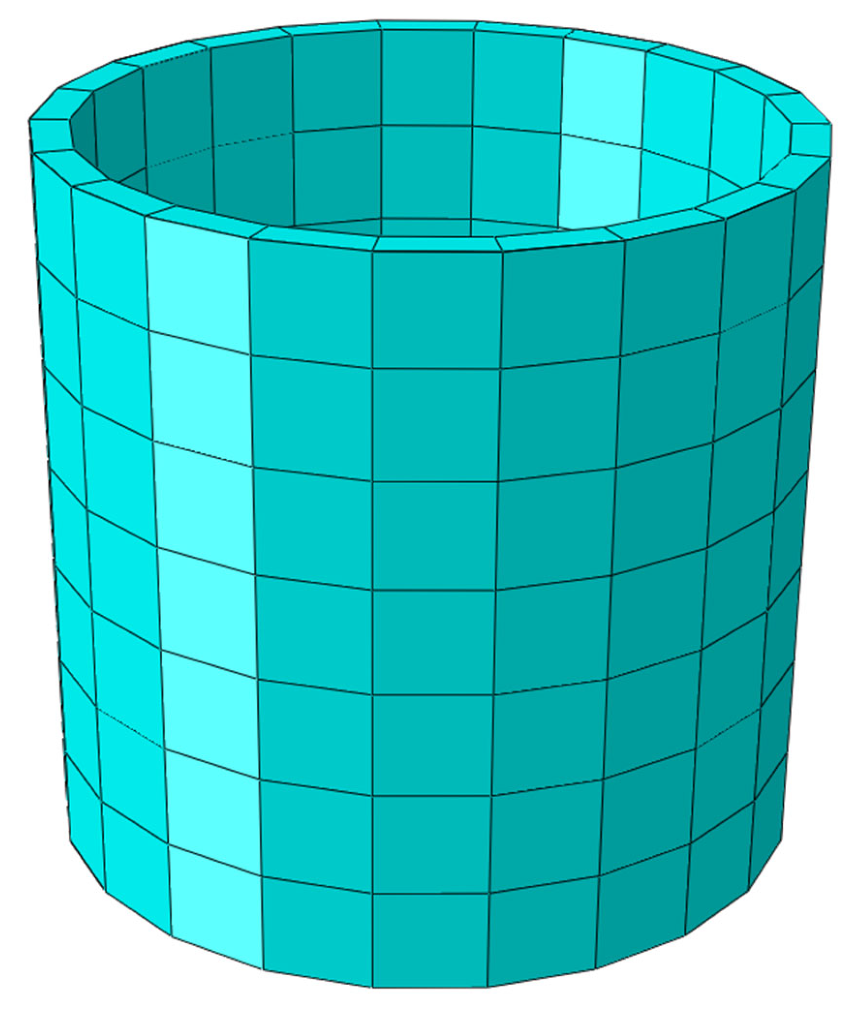
Figure 2.
Representation of the 3D model and homogenized section of the corroded manhole segment. (a) 3D model of the degraded concrete segment with detailed mesh capturing irregular corrosion patterns; (b) repaired segment showing the three-layer protective coating applied to the degraded area, with color-coded layers representing different materials; (c) homogenized cross-section of the repaired segment, represented as shell elements for simplified simulation.
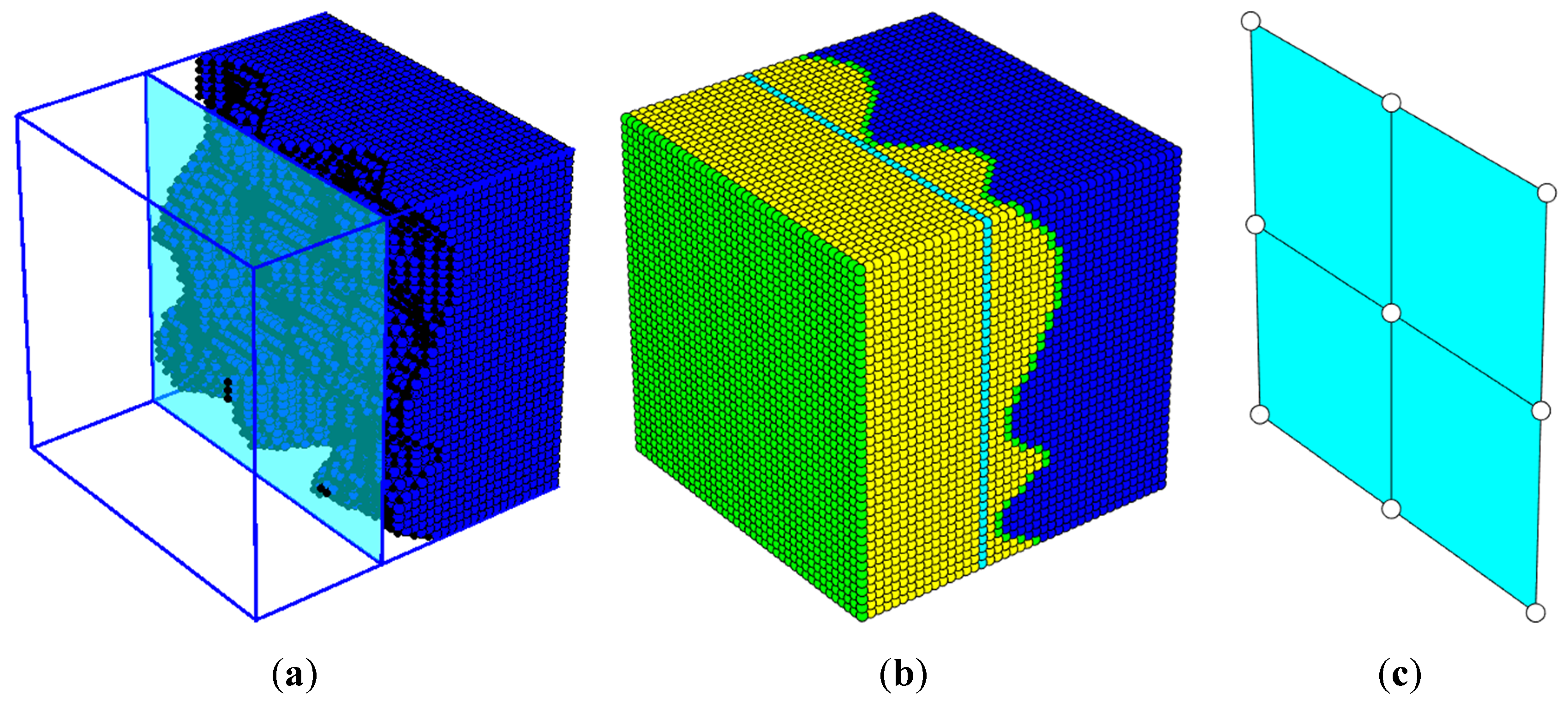
Table 1.
Parameters in A, D, and R matrices for the original undamaged concrete material with a wall thickness of 120 mm.
Table 1.
Parameters in A, D, and R matrices for the original undamaged concrete material with a wall thickness of 120 mm.
| A matrix | D matrix | R matrix |
|---|---|---|
Table 3.
Changes in A, D, and R stiffness values for the least corroded segment with a volume loss of , comparing original, corroded, and repaired conditions.
Table 3.
Changes in A, D, and R stiffness values for the least corroded segment with a volume loss of , comparing original, corroded, and repaired conditions.
| Changes in stiffness |
Deteriorated vs initial |
Repaired vs initial |
Repaired vs deteriorated |
|---|---|---|---|
| [%] | -10.19 | -8.45 | 1.94 |
| [%] | -22.78 | -7.93 | 19.23 |
| [%] | -10.19 | -7.99 | 2.45 |
Table 4.
Effective material parameters for the homogenized repaired section with an effective thickness of mm, showing both effective and total thickness values..
Table 4.
Effective material parameters for the homogenized repaired section with an effective thickness of mm, showing both effective and total thickness values..
| Effective parameters |
from D matrix | from A matrix | from R matrix |
|---|---|---|---|
| / [MPa] | 30,993 (5,337) | 30,993 (17,243) | - |
| [-] | 0.24999 | 0.24995 | - |
| [MPa] | 11,623 (2,002) | 11,622 (6,466) | - |
| / [MPa] | - | - | 9,685 (5,387) |
Table 5.
Parameters in A, D, and R matrices for a heavily corroded manhole segment with 38.27% volume loss and subsequent repair.
Table 5.
Parameters in A, D, and R matrices for a heavily corroded manhole segment with 38.27% volume loss and subsequent repair.
| A matrix | D matrix | R matrix |
|---|---|---|
Table 6.
Changes in A, D, and R stiffness values for a segment with significant corrosion (), comparing original, corroded, and repaired states.
Table 6.
Changes in A, D, and R stiffness values for a segment with significant corrosion (), comparing original, corroded, and repaired states.
| Changes in stiffness |
Deteriorated vs initial |
Repaired vs initial |
Repaired vs deteriorated |
|---|---|---|---|
| [%] | -38.26 | -35.82 | 3.96 |
| [%] | -71.93 | -50.60 | 76.00 |
| [%] | -38.26 | -35.17 | 5.01 |
Table 7.
Effective material parameters for the heavily corroded and repaired segment with an effective thickness of mm, including values for both effective and total thicknesses.
Table 7.
Effective material parameters for the heavily corroded and repaired segment with an effective thickness of mm, including values for both effective and total thicknesses.
| Effective parameters |
from D matrix | from A matrix | from R matrix |
|---|---|---|---|
| / [MPa] | 29,296 (1,940) | 29,298 (11,853) | - |
| [-] | 0.24999 | 0.24978 | - |
| [MPa] | 10,989 (727) | 10,987 (4,445) | - |
| / [MPa] | - | - | 9,156(3,704) |
Disclaimer/Publisher’s Note: The statements, opinions and data contained in all publications are solely those of the individual author(s) and contributor(s) and not of MDPI and/or the editor(s). MDPI and/or the editor(s) disclaim responsibility for any injury to people or property resulting from any ideas, methods, instructions or products referred to in the content. |
© 2024 by the authors. Licensee MDPI, Basel, Switzerland. This article is an open access article distributed under the terms and conditions of the Creative Commons Attribution (CC BY) license (https://creativecommons.org/licenses/by/4.0/).
Copyright: This open access article is published under a Creative Commons CC BY 4.0 license, which permit the free download, distribution, and reuse, provided that the author and preprint are cited in any reuse.


