1. Introduction
Low drilling efficiency of deep well section is the bottleneck problem affecting the drilling cycle and cost of deep well and ultra-deep well [
1,
2,
3]. Frequent tripping and tripping of deep well section due to poor formation drillability and short bit life is one of the main reasons for low drilling efficiency. Based on incomplete statistics, the tripping time for changing the drill bit is often longer than the pure drilling time of the drill bit in the deep well section over 6000 meters. The deeper the well depth is, the higher the tripping time ratio is. The last 1246m opening of Well Pengshen 6 (Well depth: 9026m, total drilling period: 561 days) recorded as the deepest vertical well in Asia took 200 days, accounting for 35.7% of the total drilling period; Tripping 21 times, accounting for 34.4% of the total (61 times); Tripping time is 52.5 days, accounting for 26.1% of the total drilling time of this spud. The pure drilling time of this spud is only 24.9 days, and the tripping time is more than twice of the pure drilling time. In the deep formation, the combined action of drilling fluid column pressure and confining pressure makes the rock stratum more compact, the rock drillability worse and the bit life shorter, so the tripping frequency for changing the bit is higher, and the single tripping time for drilling in the deep well section is longer. Therefore, the high frequency of bit replacement and the increase of single tripping time make the problems of low drilling efficiency and high cost caused by tripping and bit replacement in deep drilling especially prominent.
Deep wells and ultra-deep wells increase year by year in China. The exploration and development of deep oil and gas resources is the main way to achieve the strategic succession of oil and gas resources in the oil field [
4]. Some achievements have been made in the “deep engineering” implemented in the field of oil and gas exploration and development. Key technologies such as ultra-high strength casing, drill pipe, drilling fluid and measurement and control instruments have been overcome. More than 8000 meters of “underground Mount Qomolangm” wells are emerging [
5,
6]. In recent years, several scientific special deep wells of ten thousand meters have been deployed, and the early drilling test of the first deep well of ten thousand meters has been started in the Fuman Oil Field of Tarim Basin in Xinjiang, and the deep well of ten thousand meters in Xinjiang and Sichuan has been drilled [
7]. However, it is still difficult to solve the problems of long drilling cycle and high cost caused by frequent tripping and bit replacement in the deep well section of “underground Mount Qomolangm”, which directly affects the scale of “underground Mount Qomolangma” well and significantly hinders the implementation of “deep underground engineering” in China.
One-time drilling “refers to the drilling technology in which one drill bit and one set of downhole drilling tools are combined to drill one spud or all drilling footage of the well section in one time, which has the prominent advantages of saving drill bit, improving drilling speed, shortening drilling cycle and reducing drilling cost [
8]. One-time drilling “is a comprehensive technical method, the essence of which is to maximize the rock breaking capacity of the drill bit through the comprehensive application of various means conducive to improving the rock breaking efficiency of the drill bit, so as to completely avoid tripping caused by changing the drill bit halfway. One-time drilling “technology is a technology gradually formed due to the economic development of shale oil and gas and tight oil and gas (unconventional oil and gas) in North America, and it is known as one of the ten major scientific and technological advances in international petroleum in the same year. In the shale oil and gas horizontal well drilling in the United States, the “one drilling” of a single well section gradually becomes normal, and the “one drilling” of multiple well sections is not a case. The footage completed by “one drilling” ranges from hundreds of meters to thousands of meters, and the longest “one drilling” footage has exceeded 6000 meters [
9,
10,
11,
12]
. However, in the long well section and ultra-long well section, “one drilling” is realized. At present, it is mainly in the horizontal section with shallow burial depth (generally less than 2000m). The stratum has good homogeneity and good drillability. In the strata difficult to drill with large burial depth, poor drillability, heterogeneity or frequent changes in formation lithology, it is very difficult to “drill in one time” the long well section.
One-time drilling “technology is a systematic project, which must be comprehensively considered from geology, wellbore structure, borehole profile, drilling fluid and tool equipment, among which advanced and efficient special tools are the basis to guarantee the implementation effect of” One-time drilling “. Among many key tools, high quality and high efficiency drill bit is the most basic condition to realize “one drilling”. If the drill bit has short service life and less footage, one drilling is impossible.
2. New Thought of Downhole Self-updating PDC Bit Technology
Downhole bit updating technology “is a new technical idea that the old bit is directly updated underground without tripping. Generally, when the rock breaking efficiency is seriously reduced or the rock breaking drilling can not be continued due to the wear of the bit, the service life of the bit ends and the drilling can only be continued after the bit is pulled out and replaced. It is not necessary to pull out and change the drill bit with the “downhole bit renewal technology”, but the worn cutting structure can be replaced by the preparatory cutting structure of the drill bit through the ground control, so as to complete the bit renewal in the downhole. The updated bit is like a new bit and can be directly started to drill, thus avoiding the tripping process of changing the bit. The “downhole bit updating technology” can be used to implement one or more downhole updates without tripping out. A single run of the bit can be used as two or more bits, which can increase the service life and continuous drilling time of the bit several times, so the tripping time can be greatly reduced, the travel mechanical drilling speed can be increased, and the drilling cycle and cost can be reduced. This is very important for the value of high cost oil and gas drilling such as deep water.
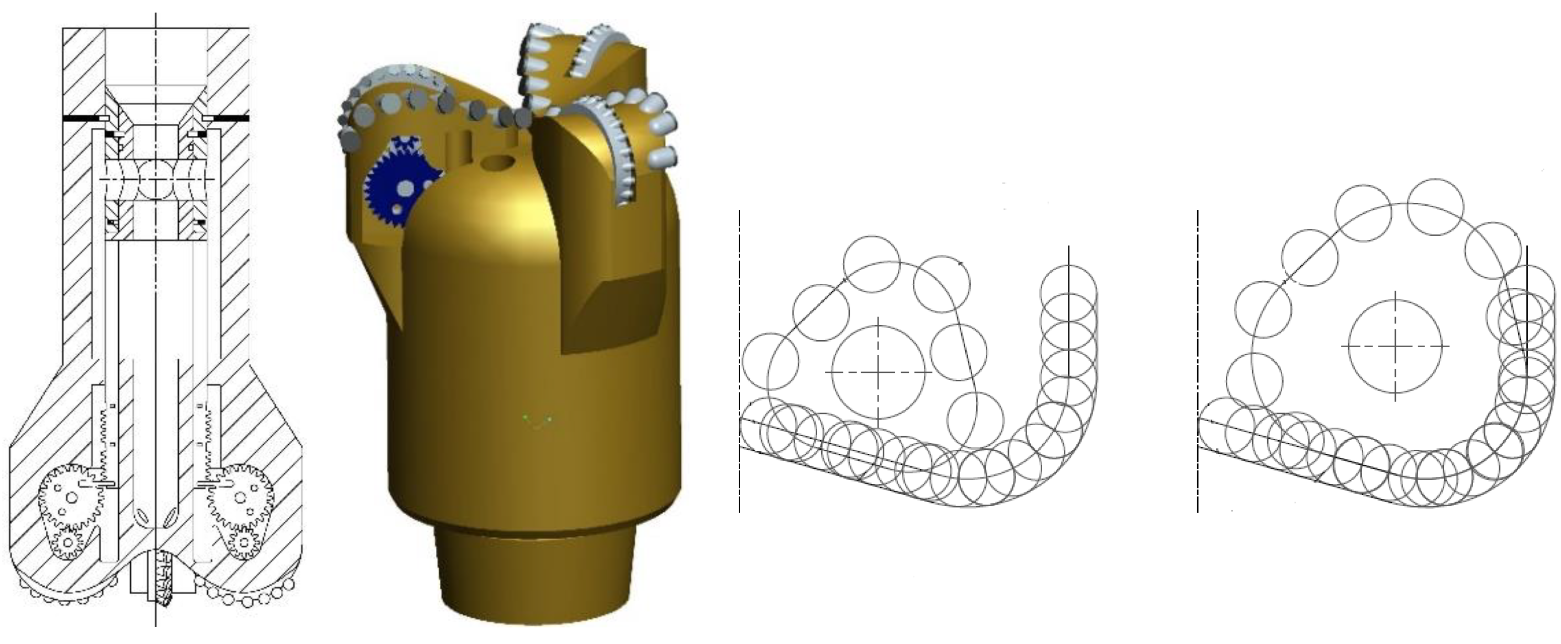
Schlumberger proposed the indexable roller bit technology [
13]. As shown in
Figure 1, the roller on the bit is equipped with a driving mechanism which is connected with the rotation mechanism. The driving mechanism can drive the rotation mechanism to rotate to a predetermined position and fix it. The indexing mechanism rotates the cone and enables the teeth at different positions on the cone to break rock. When the teeth at a certain position are worn, the indexing mechanism can be driven to rotate and fix again to break rock for the teeth at a new position.
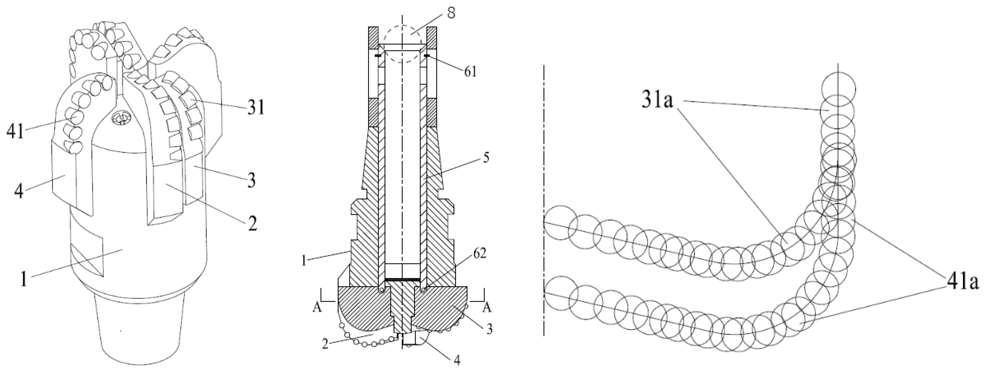
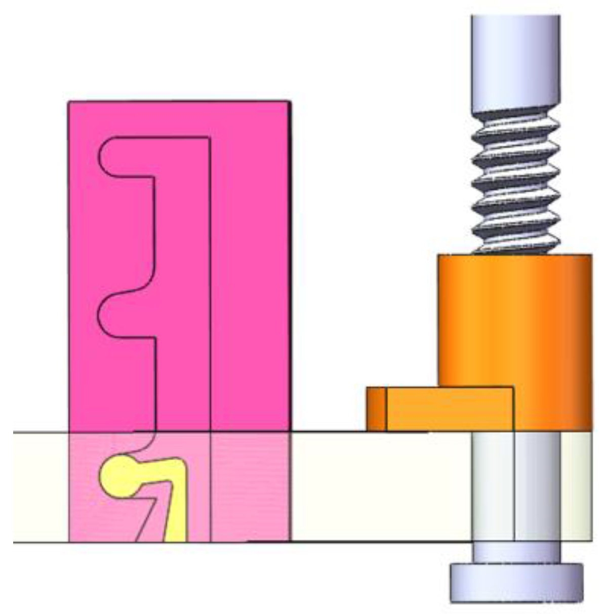
In 2018, the Drill Research Institute of Southwest Petroleum University proposed a long life PDC bit with a flat blade (
Figure 2) [
14]. The drill bit has a retractable translation blade, and the translation blade is in a retracted state at the initial working stage of the drill bit, and does not participate in rock breaking. When the cutting teeth on the fixed blade reach a certain degree of wear, the cutting structure of the flat blade stretches to the preset working position and is locked through the ground remote control, so as to replace the old and new cutting structures.
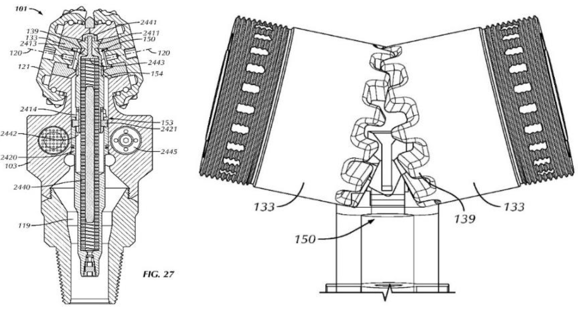
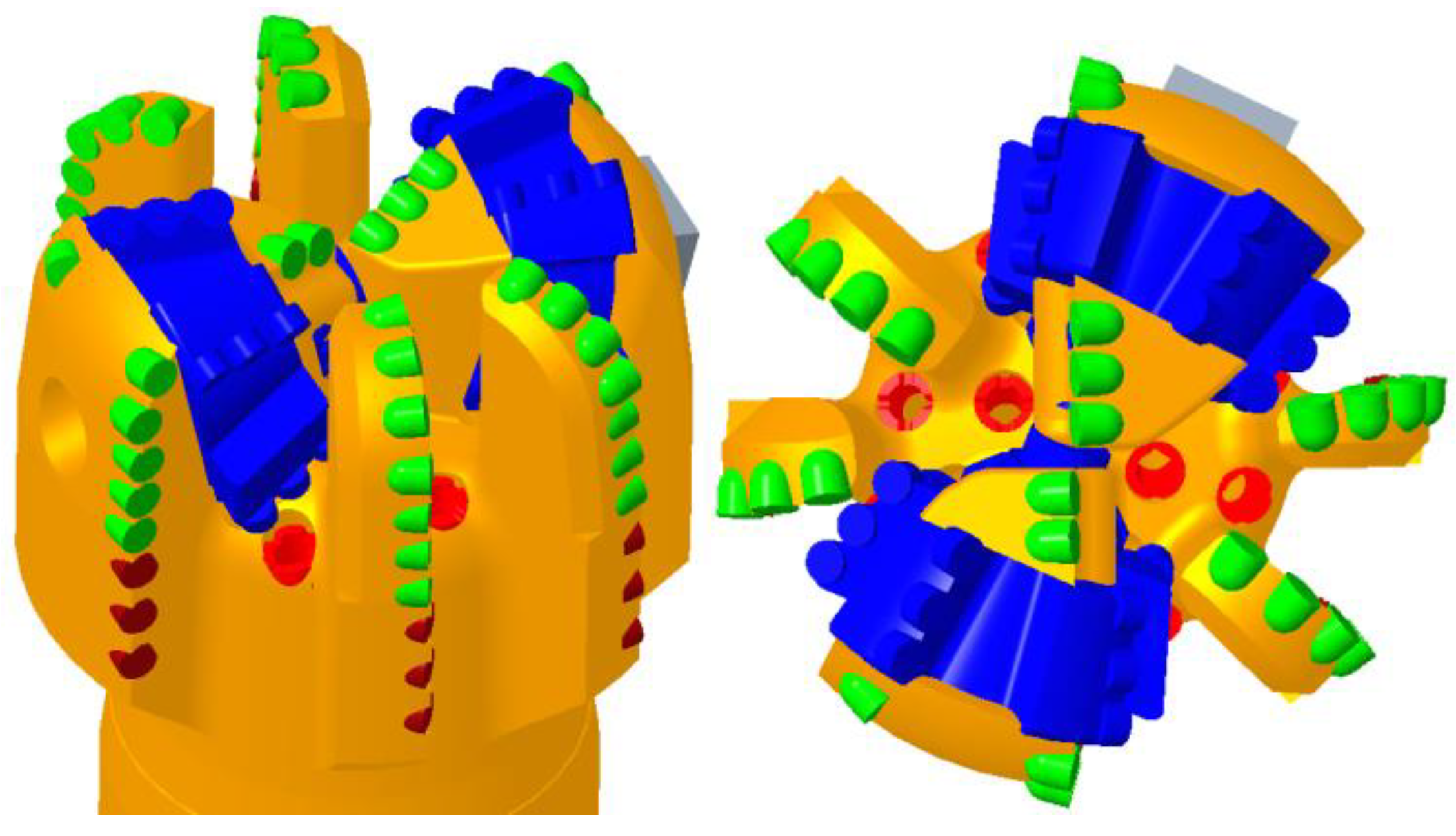
NOV developed PDC drill bit which realized the retraction and retraction of part of cutter wings by changing hydraulic parameters [
15], as shown in
Figure 3. The retractable cutter wings of the drill bit are in retraction state at the initial working stage. When the drill bit is worn, part of cutter wings stretch out by hydraulic control, and the cutting structure is reinforced. The scheme can compensate for the wear of the cutting structure of the drill bit once, and extend the service life and continuous drilling capacity of the drill bit [
16,
17,
18,
19,
20].
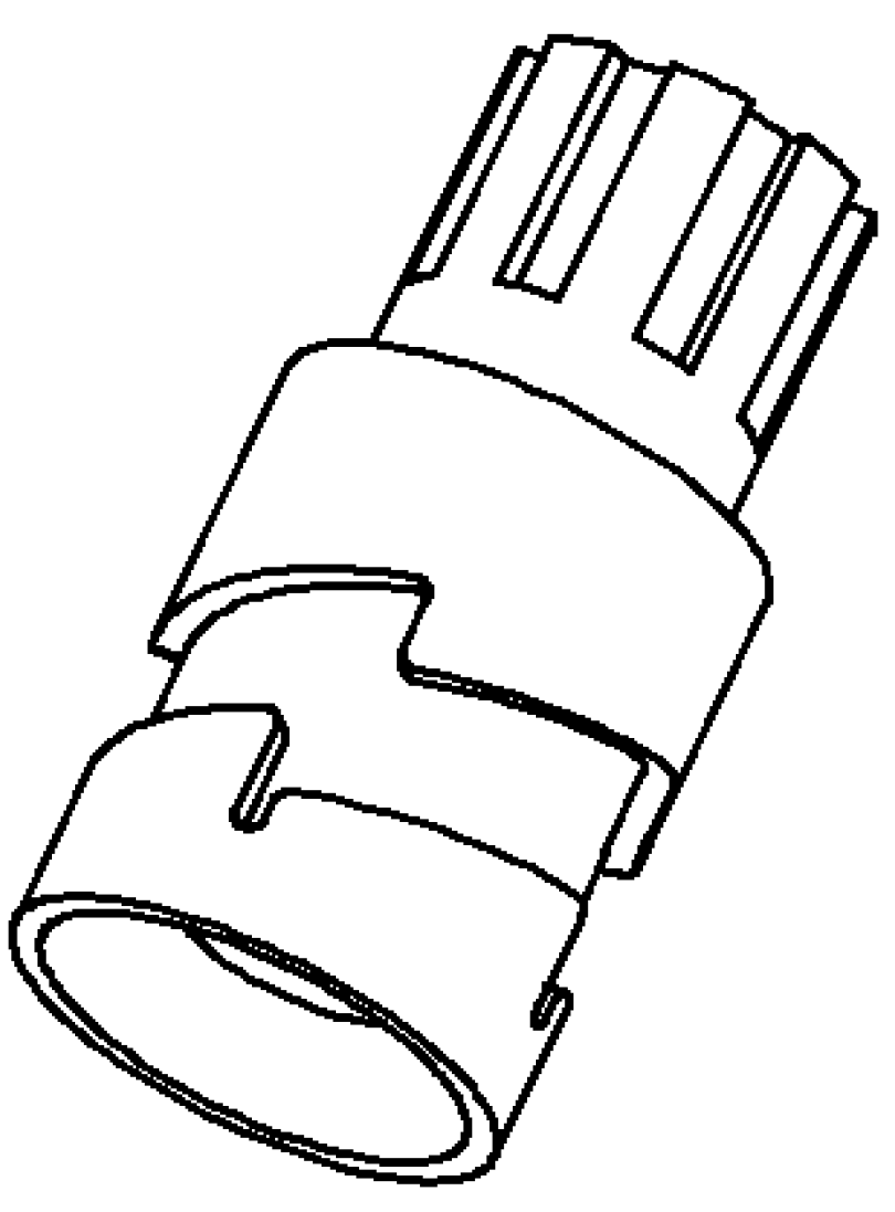
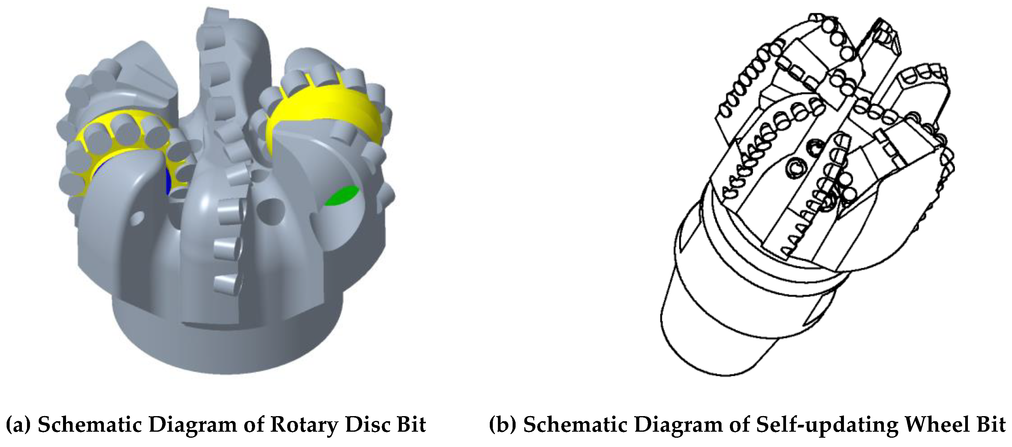
On the basis of disc cutter bit and cross scraping PDC bit technology, the bit research institute of Southwest Petroleum University puts forward the bit with renewable cutting structure - rotary disc cutter bit technology (
Figure 4, left), i.e., the rotary cutter wing (disc cutter) of the bit can be controlled to rotate [
14]. The basic idea of this technology is that the disc cutter on the drill bit can be rotated to a preset working position and locked by control. When the bit is working underground, when the initial cutting teeth are worn, the disc cutter can be rotated on the ground through remote control, so that the worn cutting teeth are replaced with new cutting teeth to continue drilling instead of the worn cutting teeth, so that the bit can complete multiple updates of the cutting structure in the underground, achieving the effect of “replacing the bit underground without tripping out”. On the basis of the above ideas, the Drilling Research Institute of Southwest Petroleum University continues to put forward the technical scheme of non-disc cutter bit, and the disc cutter is designed into curved polygon. The curved edge of the non-disc cutter can be designed according to the cutting contour of the drill bit to match the cutting contour of the drill bit (as shown in
Figure 4, right). This scheme breaks the constraint of the idea of circular disc cutter, and can be customized and flexibly designed according to the use environment and conditions of the drill bit. The number of updates of the cutting structure of the drill bit is determined by the number of sides of the polygon [
21,
22,
23,
24,
25,
26].
3. Scheme Design of Rotary Self-Updating Bit
Since the translational self-renewal bit needs to be provided with multiple cutter wings in a limited space, especially in the core area of the bit, it is impossible to provide multiple cutter wings at the same time, so the translational self-renewal bit will be limited in actual application. However, the updating structure of the rotary self-renewal bit is updated through the circular disc cutter structure, occupying less bit space. The rotary self-renewal bit is composed of a trigger mechanism, a driving mechanism, a limiting mechanism and a locking mechanism. According to different driving structures, the rotary self-renewal bit can be divided into a rack drive self-renewal bit, a worm drive self-renewal bit and a ratchet drive self-renewal bit.
3.1. Rack Drive Self-Updating Drill
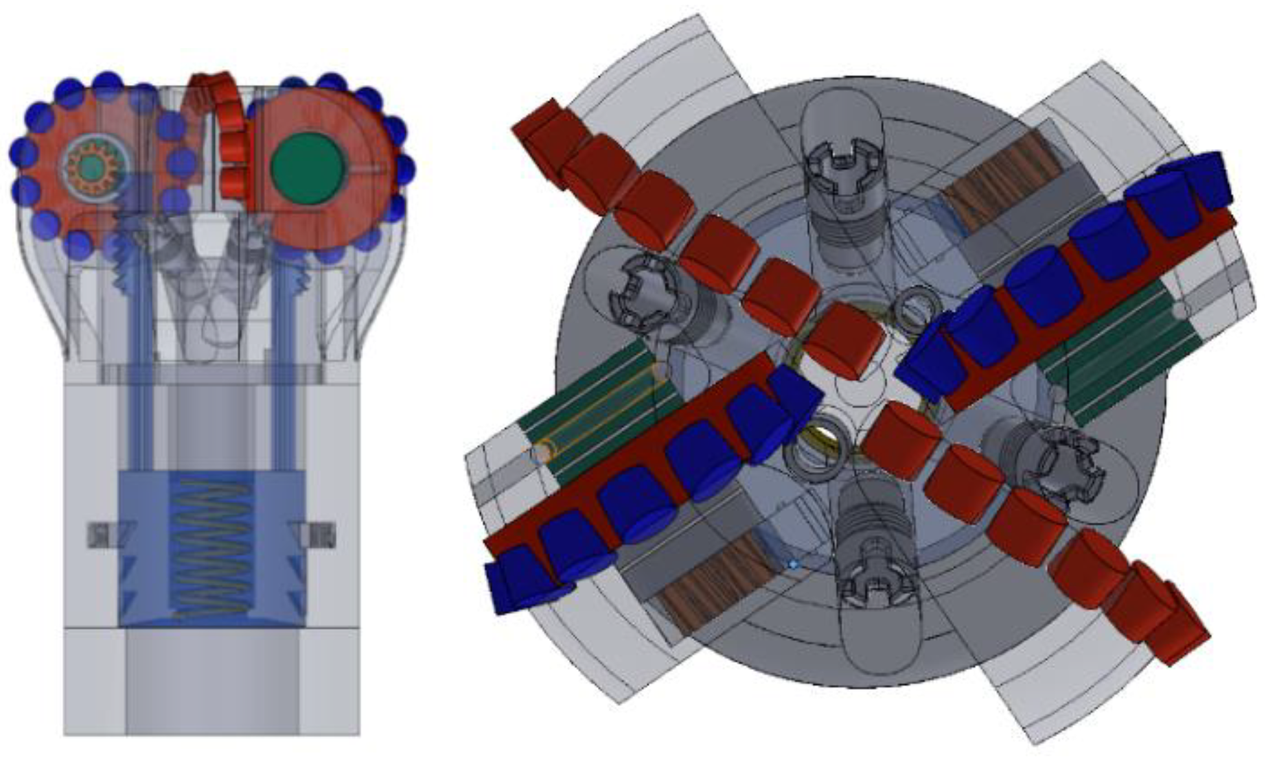
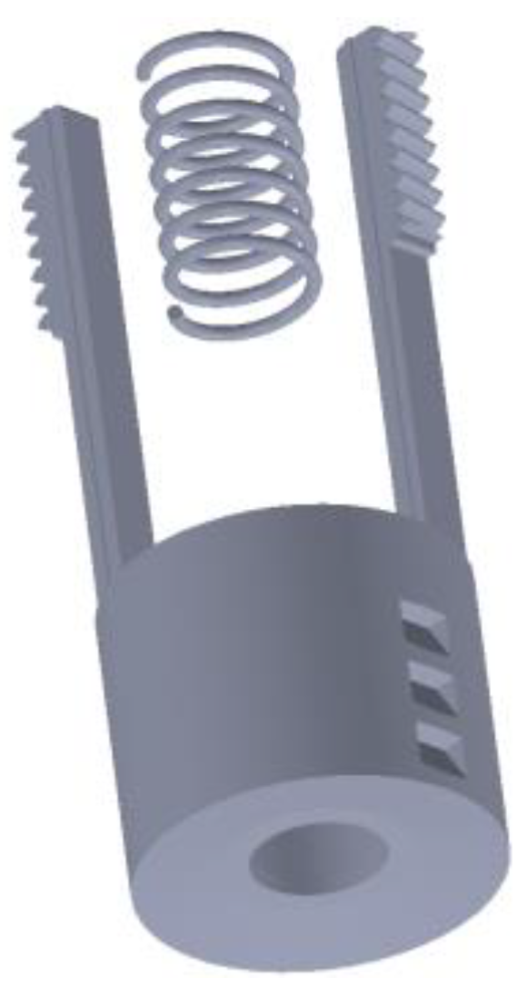
The rotary self-renewal drill bit comprises a self-renewal wheel, a wheel shaft, a self-renewal gear, a triggering mechanism, a driving mechanism, a limiting and locking mechanism, and a spring reset mechanism. The drill bit driving mechanism is a gear rack structure, and the triggering mode is triggered by a ball throwing and pressure holding mode. The limiting and locking mechanisms are triangular components. The three-dimensional model of the rack driving self-renewal drill bit is shown in
Figure 5.
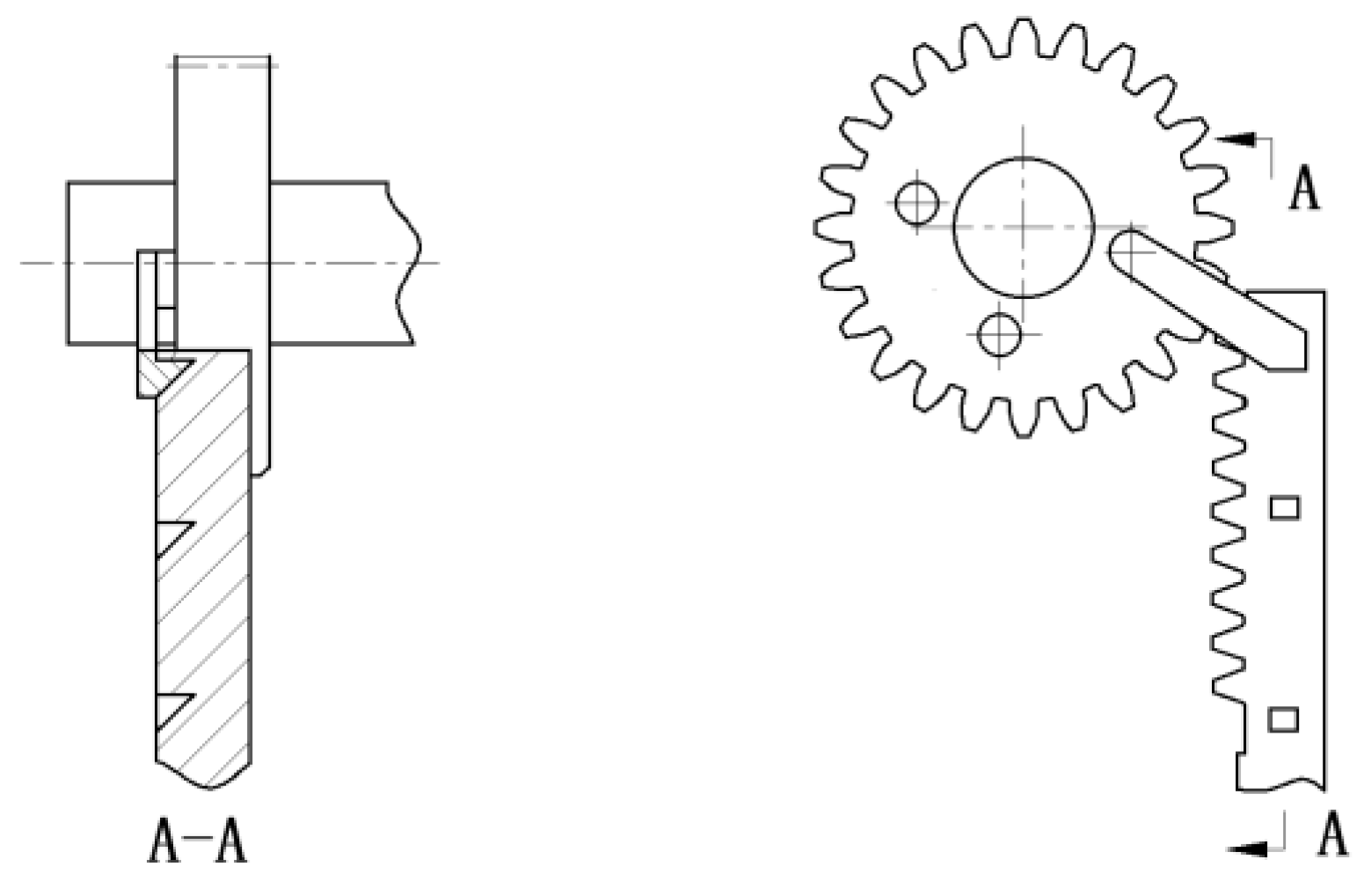
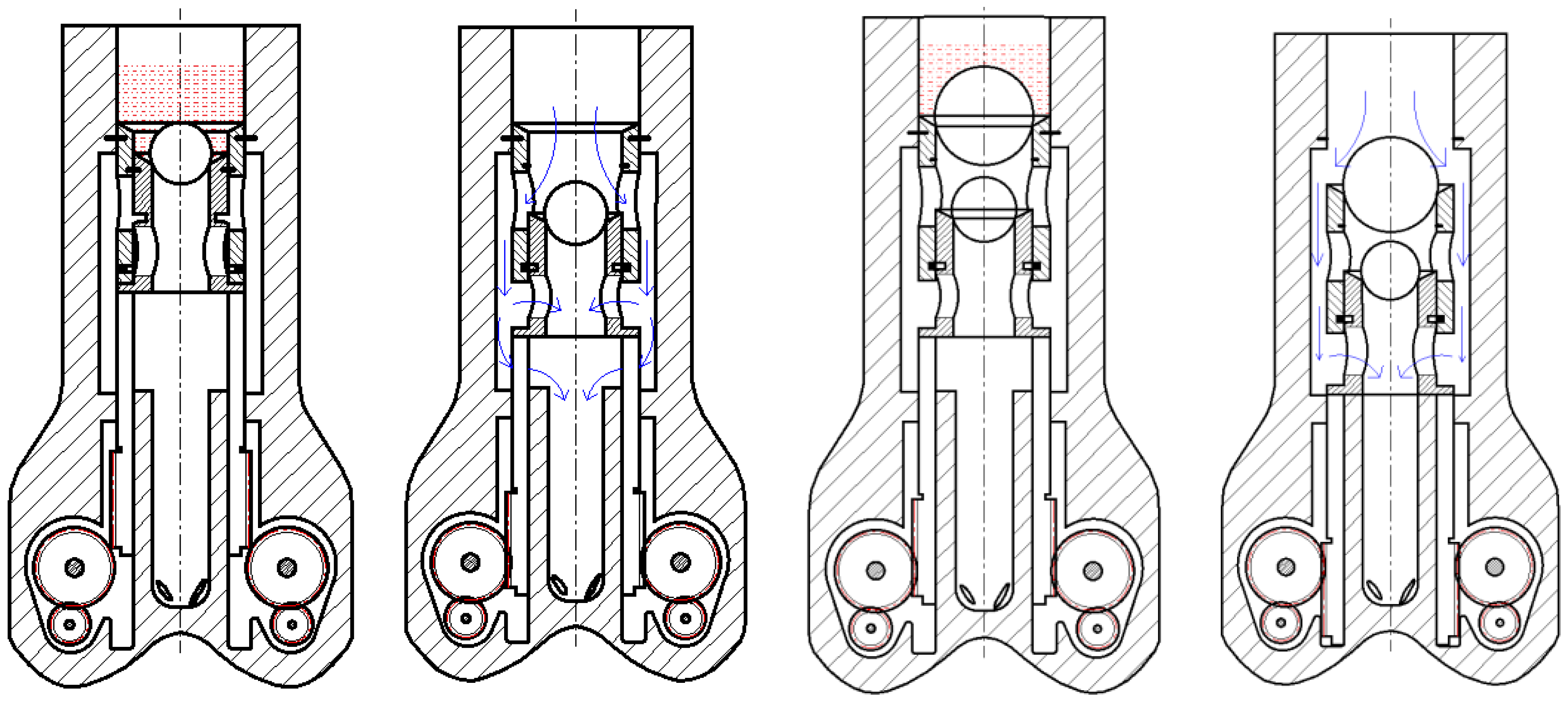
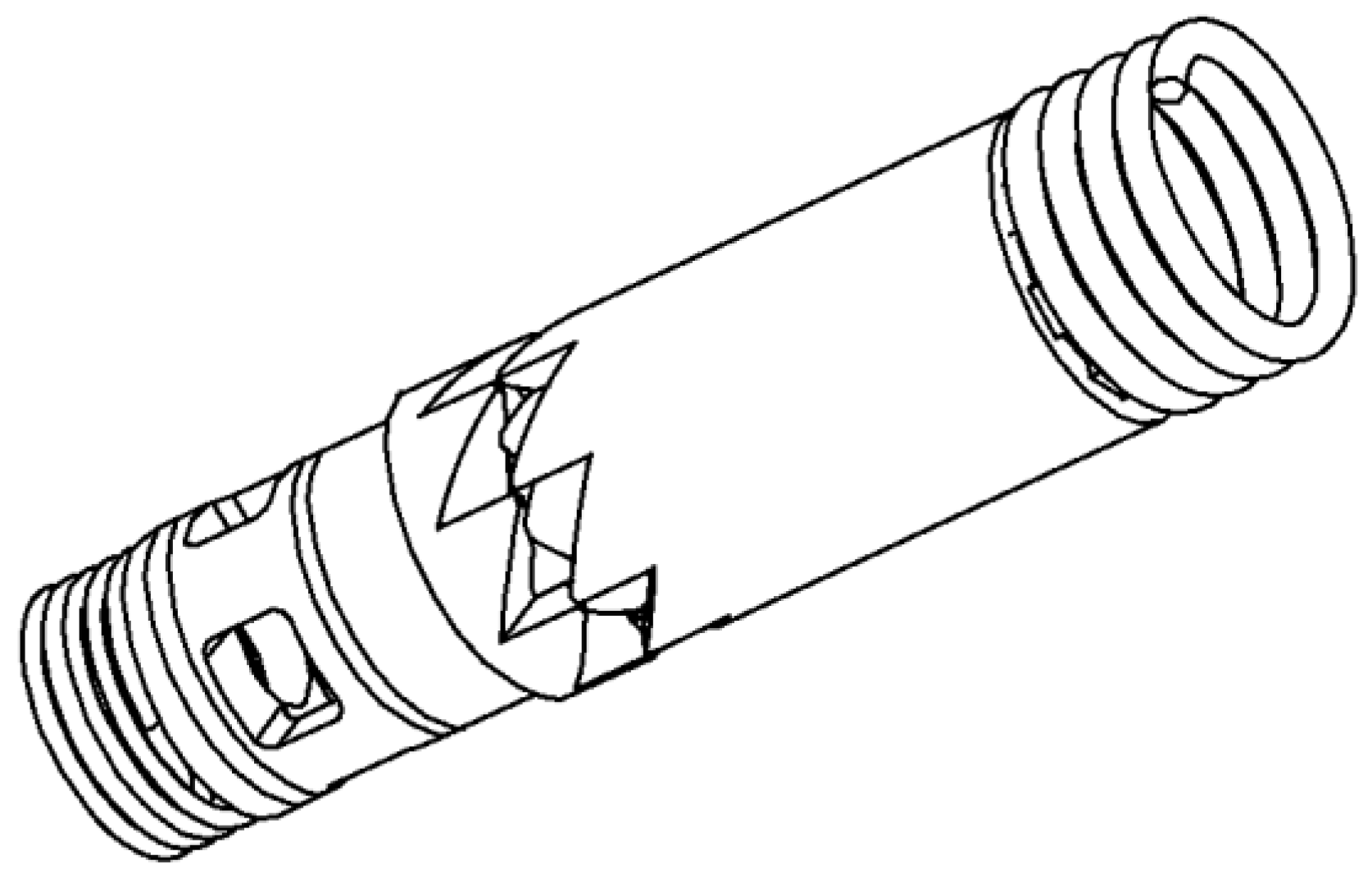
The self-renewal wheel in the drill bit is connected with the drill bit body through the wheel shaft, the gear and the wheel shaft are connected through the key, the gear and the rack mesh with each other, the rack and the piston member form a fixed connection, the spring reset mechanism is arranged between the piston member and the drill bit body, and a groove is arranged at the corresponding position of the piston member and the prism lock member. When the drill bit bottom works normally, the self-renewal tooth is equivalent to the fixed tooth scraping the bottom rock, the spring reset mechanism is in a compression state, so that the piston member moves downward. Due to the unidirectional locking performance of the prism member, the piston is in a static state, so as to lock the rack. Due to the meshing effect of the gear and rack, the gear is locked, and finally the self-renewal wheel is locked. When the cutting teeth on the drill bit have. Wear and tear, when the drill cutting teeth need to be renewed in the bottom hole, Lift the drill bit away from the bottom of the well for a certain distance, and increase the displacement of drilling fluid by throwing balls to hold the pressure, as shown in
Figure 6. Apply an upward pressure on the piston pressure bearing surface. As the prism lock can only be locked downward, the piston pushes the rack to move upward under the pressure of drilling fluid, as shown in
Figure 7. The rack drives the gear to rotate, and the gear drives the self-regulating wheel to rotate. When the piston moves for a certain distance, the prism is locked under the action of the spring, so that the cutting teeth of the drill bit are renewed once.
The key structural parameters of the rack-driven self-renewal drill bit mainly include the drill bit parameters, reset spring parameters, gear rack structural parameters, axle structural parameters, etc. The specific values are shown in
Table 1.
3.2. Worm-Driven Self-Renewal Drill
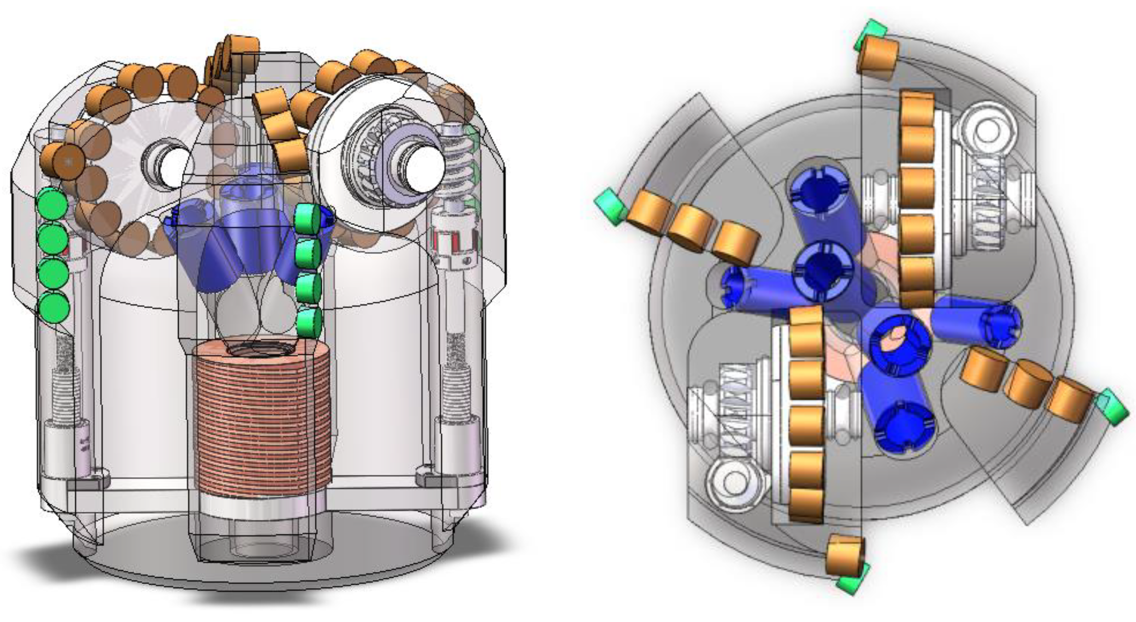
The 3D model of the worm driving self-renewal drill bit is shown in
Figure 8. The driving mechanism is the worm gear mechanism, the trigger mechanism is the piston component connected with the rack, the lower end of the piston component is provided with a bearing surface, the transmission structure is a ball screw, the core of the drill is provided with a reset spring mechanism, and the limiting and locking mechanisms are of a ratchet groove structure.
Self-renewal wheel axis is vertical to the radial direction of the drill bit, and is connected with the drill bit through the wheel shaft to realize the support on both sides. At the same time, the axial locking of the Self-renewal wheel is realized through the ball. Self-renewal wheel, worm wheel and wheel shaft are connected through the spline. The worm axis is parallel to the drill bit axis. The lower end of the worm is connected with the ball screw through the coupling. A bearing is arranged at the upper end of the worm and the lower end of the screw. The piston is connected with the ball screw through the connecting rod. A ratchet groove limiting locking mechanism is arranged at the connecting rod, as shown in
Figure 9. When the drill bit works normally, the cutting teeth on the renewable wheel are fixed teeth. Due to the self-locking effect of the worm wheel and worm, the worm wheel cannot drive the worm to rotate, so as to ensure that the renewable wheel will not rotate reversely and the spring at the center of the drill bit is in a compressed state, making the piston member move downward. Due to the one-way locking performance of the ratchet groove, the piston is in a balanced state, so as to lock the ball screw. When the drill bit needs to be updated, the pressure on the bearing surface of the piston increases, so that the piston moves upward, driving the ball screw to move, driving the worm to rotate, and finally driving the renewable wheel to rotate. When the connecting rod moves to the ratchet groove position, limiting and locking can be completed. updates were made.
The key structural parameters of the worm drive self-renewal drill bit mainly include the drill bit parameters, reset spring parameters, worm gear and worm gear structural parameters, wheel shaft structural parameters, ball screw and other parameters, and the specific values are shown in
Table 2.
3.3. Ratchet Drive Self-Renewal Drill
Three-dimensional model of ratchet drive self-renewal drill bit is shown in
Figure 10. The drive mechanism is ratchet mechanism, the trigger mechanism is ratchet shaft, the lower end of the ratchet shaft is provided with bearing surface, the transmission structure is a pair of bevel gears, a return spring mechanism is provided between the bevel gear and the ratchet shaft, and the limit and locking mechanisms are ratchet groove structures on the ratchet shaft.
The assembly drawing of drill parts is shown in
Figure 11. A self-renewal wheel is provided on the support blade, and a self-renewal gear is provided on the self-renewal wheel. The self-renewal wheel is rotatably connected with the support blade through a wheel shaft, and a cone wheel is provided at one end of the self-renewal wheel; A drive shaft, a ratchet shaft, a spring and a sliding pin are arranged inside the bit body. One end of the drive shaft is a tapered wheel, and the other end is a spline groove. The tapered wheel of the drive shaft and the tapered wheel of the self-regulating wheel mesh with each other. One end of the ratchet shaft is an upper spline. The ratchet shaft is provided with a ratchet groove, and the lower end of the ratchet wheel is provided with a bearing surface (as shown in
Figure 12). The upper spline of the ratchet shaft and the spline groove of the drive shaft cooperate with each other, and the sliding pin and the ratchet groove form a sliding fit. The spring is arranged between the ratchet shaft and the drive shaft, and the sliding pin is arranged between the bit and the joint. When the drill bit works normally, the drilling fluid pressure and spring elastic force are balanced mutually, the sliding pin locks the ratchet shaft rotation in the ratchet groove, and the self-leveling wheel is locked by the transmission mechanism. When the cutting teeth at the bottom of the well are worn and need to be replaced, the drill bit is lifted to a certain distance from the bottom of the well, and the drilling fluid pressure is increased by the ground equipment. The drilling fluid pushes the entire ratchet shaft upward and compresses the spring. At this time, the sliding pin and the ratchet groove on the ratchet shaft slide together, and the sliding pin contacts the lower slope of the ratchet groove; Due to the existence of the slope on the ratchet groove, the slope will push the ratchet shaft to continue to rotate until the sliding pin is located at the lower dead center of the ratchet groove; At this time, the displacement of drilling fluid is reduced. Under the action of spring, the ratchet moves down in axial direction, and the sliding pin gradually reaches the upper slope of the ratchet groove; Push the ratchet shaft to rotate continuously under the action of the slope until the ratchet shaft is located at the top dead center of the ratchet groove; In this way, the ratchet shaft moves and rotates at the same time. The upper end of the ratchet shaft is provided with an upper spline. The drive shaft spline groove, and the spline and the spline groove cooperate with each other. The ratchet drives the drive shaft to rotate. The conical wheel at the upper end of the drive shaft meshes with the conical wheel on the self-regulating wheel to drive the self-regulating wheel to rotate, so that the self-regulating teeth are turned over to the outer surface of the blade, forming a part of the cutting structure of the drill bit, so that it has the underground self-regulating capacity and achieves the purpose of extending the service life.
The key structural parameters of ratchet drive self-renewal bit mainly include bit parameters, reset spring parameters, cone wheel parameters, wheel shaft structural parameters, ratchet wheel structure and other parts, and the specific values are shown in
Table 3.
Through the comparison and analysis of the three types of self-renewal schemes, it can be seen that the advantage of rack-and-pinion drill bit is that the rack-and-pinion structure is relatively simple, the reliability is good, and the disadvantage is that the control accuracy is low, and the gear is easy to buckle; Worm and worm drive drill has the advantages of strong self-locking capacity of worm and worm, high rotation control accuracy, and the disadvantages of complex drill structure and precise design of pump pressure and spring rigidity; The advantage of ratchet drive bit is that the bit is updated frequently, while the disadvantage is that the hydraulic structure of the bit is difficult to be designed and the internal transmission structure is complex.
4. Comparative Analysis of Self-Updating PDC Bit
4.1. Triggering Device
Triggering devices include mechanical trigger, electric trigger, pneumatic trigger and hydraulic trigger. Common trigger devices include ball throwing pressure holding trigger device, piston sliding trigger device and drilling pressure start trigger device.
The ball throwing triggering device comprises a pressure holding ball put into the ground and a multi-level one-way triggering mechanism arranged between the bit body and the transmission device or the indexing cutter wing. The multi-level one-way triggering mechanism comprises at least two layers of inner and outer nested sliding sleeves arranged in the drilling fluid flow channel of the bit body, the top surfaces of the inner and outer sliding sleeves are used for receiving the pressure holding ball, and the innermost layer of the inner sliding sleeve is used for driving the transmission device or the indexing cutter wing; The inner sliding sleeve of each layer can slide up and down in the inner cavity of the outer sliding sleeve, and the outermost outer sliding sleeve can slide up and down in the inner cavity of the drilling fluid flow channel. Shear pins are provided between the inner and outer sliding sleeves of each layer, and between the outermost outer sliding sleeve and the inner wall of the drilling fluid flow channel; The inner and outer sliding sleeves of each layer are provided with through holes communicating inside and outside the inner cavity, and the inner sliding sleeve of each layer is provided with a limit hole above the through hole, and the outer sliding sleeve of the outer layer is correspondingly provided with a limit pin below the through hole, and the limit pin is continuously applied by the elastic mechanism to push it into the pushing force inside the limit hole, and the pressure holding process of multiple ball throwing is shown in
Figure 13.
The piston sliding trigger device (refer to
Figure 14) comprises a piston body, a return spring and a transmission structure (the rack structure in the figure). When the drill bit works normally, the pressure of the drilling fluid on the piston and the pre-pressure of the spring counteract each other. When the self-regulating wheel needs to be renewed, the pressure of the drilling fluid is increased to push the piston compression spring to move upward, so as to realize the self-regulating trigger function of the drill bit.
A bit pressure starting triggering device (refer to
Figure 15), wherein the elastic coefficient of the safety spring above the pressing member is greater than the elastic coefficient of the starting spring below the rotating member, and the pressure at which the safety spring deforms is 2-3 times the maximum value of the normal working bit pressure. When the bit is under normal bit pressure, the press-type rotating device will not start; When the bit needs to be renewed, the upper safety spring will be deformed after 2-3 times of the maximum conventional weight on bit is applied to the bit, and the press-type rotating device under the safety spring starts to work.
4.2. Transmission Structure Device
The transmission device comprises a gear rack transmission structure, a bevel gear structure, a worm gear and worm structure and other different structures, wherein the gear rack transmission structure comprises a rack and a gear set, the rack is pushed downward by a trigger device, the rack and the gear set are engaged to drive the gear set to rotate, the gear set is composed of one or more gears engaged, and the gear set drives the indexing cutter blade to rotate; The bevel gear structure is composed of a pair of bevel gears, which are meshed with each other to realize 90 ° rotation transmission. The other bevel wheel is driven by the bevel wheel, so as to drive the rotation of the self-updating wheel; The worm gear and worm gear structure consists of worm gear and worm gear. The mechanism has self-locking function. The worm gear can only be driven by the worm gear to rotate. Self-locking can be carried out for the self-locking gear. No separate locking mechanism is required.
4.3. Limit and Locking Device
The limiting and locking mechanism comprises a limiting pin and a limiting slot structure, a ratchet structure. The limiting pin and the limiting slot can be arranged on the transmission device or a trigger device. The elastic mechanism continuously applies a thrust pushing the limiting pin to the transmission device, and a limiting slot is arranged on the limiting pin of the corresponding transmission device, and the spacing between the limiting slots matches the angle between the limiting slots. The limiting pin is inserted into the limiting slot when the limiting pin is inserted into the limiting slot. When the transmission device continues to move downward, the limiting pin is pushed to exit the limiting slot, and the limiting pin exits the corresponding limiting slot; The pawl and ratchet structure (
Figure 16) comprises a push rod, a rotating body, a pawl and a ratchet wheel. The push rod is driven by a trigger device to move up and down in the drill bit body. The push rod and the rotating body are connected to drive the rotating body to rotate automatically. The rotating body has an inner cavity. The inner cavity is provided with a pawl and a ratchet wheel. The pawl and the rotating body are elastically connected. A plurality of teeth are arranged on the outer edge of the ratchet wheel. When the push rod moves up to drive the rotating body and its pawl to rotate, the pawl will freely pass through the teeth. When the push rod moves down to drive the rotating body and its pawl to rotate in a reverse direction, the pawl and a certain clamping wheel will engage to drive the ratchet wheel to rotate.
4.4. Update of Structural Units
The rotary updating structure device comprises two structures: a rotary disc cutter and a self-updating wheel. The axis of the rotary disc cutter is perpendicular to the radial direction of the drill bit (
Figure 17a). The rotary disc cutter and the drill bit body can realize single-side or double-side support connection. The axis of the self-updating wheel is consistent with the radial direction of the drill bit (
Figure 17b). The updating wheel is connected with the drill bit body through the shaft. Self-renewal wheel can realize multiple times of downhole renewal, but the bottom hole coverage area is limited, especially the external area where the bit is easy to be worn, and the number of rotary disc cutter renewal is limited. However, the bottom hole coverage area of the bit is large, so the full coverage of the radial area of the bit can be achieved.
5. Prospect
Real-time monitoring and identification of the working state (including wear state) of the bottom hole bit has always been a difficult problem in the field of drilling engineering, which plays an important role in determining the timing of bit replacement. At present, the methods for identifying the working state of the bottom hole bit can be preliminarily divided into two types: the indirect ground monitoring and identification represented by the “mechanical specific energy principle” and the direct monitoring and identification of the bottom hole bit represented by the “intelligent bit”.
The principle of mechanical specific energy is to observe its impact on ROP by changing the bit wear parameters and bit design. MSE model is used to adjust the working parameters. Under the condition of not affecting the comprehensive wear, the ROP value is maximized in the local drilling process, so it is used as a global optimization tool and popularized for application. The intelligent bit technology is a technology to install sensors and intelligent microchips on the bit, collect the drilling stratum characteristics, bit weight on bit, torque, rotating speed and other data, identify the working state of the bit at the bottom of the hole, and adjust the drilling parameters of the bit. The use of these measurement data and customer interface helps to reduce or eliminate the low efficiency caused by bit design, bottom hole assembly and parameter selection, and is used to support the decision on the dynamic performance of the bit.
To sum up, in recent years, bit technology has been developing rapidly, which has played an important role in promoting the progress of drilling technology. In deep water and other high cost drilling projects, “downhole bit updating technology” has great application potential.
6. Conclusions
With the progress of resource exploration and development, there is an overall relationship among the response of excavation bit, drilling parameters and geological characteristics. Targeted tool/process design and drilling parameter optimization for speed and efficiency improvement have become an urgent need for (ultra-) deep and unconventional resource development. With the self-renewal bit as the representative, the self-renewal mode with remote control, strong reliability and high transfer efficiency has gradually become the key direction of research and development of long-life rock breaking tools for oil and gas wells in the world. Based on the technical idea of rotary self-renewal structure, the author explores some key problems of self-renewal bit trigger device, transmission device, limiting and locking device, and renewal structure device.
1) Compared with the method of increasing the wear resistance of cutting teeth and prolonging the service life of drill bit, the method of replacing cutting teeth at the bottom of the well is the most effective means to realize “one trip drilling” at the oil field at present. Vigorous development and promotion of this technology is expected to overcome the technical pain of low footage and difficult speed increase in the deep hard rock stratum in China.
2) Rotary bottom hole self-updating PDC bit technology relies on the self-locking characteristics of the worm wheel and worm to achieve one-way locking, which is highly reliable and can achieve no less than three times of updates. However, at present, domestic and foreign scholars are lack of research on this technology, and there is no systematic research conclusion on the wear judgment of the bit cutting structure, the new control technology, the working mechanics of the update system and the design method. It is suggested to enhance the progress of this technology.
3) The key to prolonging the service life of the drill bit is to clarify the working mechanism of the drill bit. Starting from the driving mechanism kinematics and transmission dynamics, the blocking force and its source in the driving process of excitation startup and update, the driving load in the driving process of update and the ultimate load of each component can be studied.
4) With the continuous development of artificial intelligence (AI) algorithm and intelligent oil field technology, it is necessary to strengthen the research on the self-renewal bit technology in the intelligent judgment of cutting tooth wear, the integration of multiple technologies and the optimization of well site application, so as to make greater contributions to the development of China’s crude oil efficiency and the high-efficient development of deep ground energy.
Author Contributions
Conceptualization, Xiaoao Liu and Liyuan Yang; methodology, Guodong Ji; software, Haitao Ren; validation, Qiang Wu, Jinping Yu and Xiaoao Liu; formal analysis, Liyuan Yang; investigation, Guodong Ji; resources, Haitao Ren; data curation, Qiang Wu; writing—original draft preparation, Kuilin Huang; writing—review and editing, Xiaoao Liu; visualization, Liyuan Yang; supervision, Guodong Ji; project administration, Xiaoao Liu and Jinping Yu; funding acquisition, Kuilin Huang. All authors have read and agreed to the published version of the manuscript.
Funding
This research was funded by the open fund project of the State Key Laboratory of Oil and Gas Reservoir Geology and Exploitation (Southwest Petroleum University) in 2022 (grant no.PLN2022-29), and Nanchong City-Southwest Petroleum University City School Science and Technology Strategic Cooperation Project [No.23XNSYX0018].
Conflicts of Interest
The authors declare that there are no conflicts of interest regarding the publication of this paper.
References
- Deng Hu, Jia Lichun Key Technology and Prospect of Deep and Ultra-deep Well Drilling in Sichuan Basin [J]. Gas Industry 2022, 42, 82–94.
- Yin Hu, Zhao Xiuwen, Li Qian Drill bit selection method for deep well and ultra-deep well based on Vague set of entropy weight [C]/2022 China Oil and Gas Intelligent Technology Conference - The 5th High-end Forum on Artificial Intelligence in Petroleum and Petrochemical Industry and the 8th Open Forum on Intelligent Digital Oil Field Beijing Energy Association, China University of Petroleum (Beijing), National Key Laboratory of Oil and Gas Resources and Exploration, National Key Laboratory of Heavy Oil, Baidu Intelligent Cloud, 2022: 178–185.
- Zuo Honggang, He Fuyao, Yan Weifeng, etc PDC bit customization design and application in ultra-deep wells in East China Sea [J]. Technical Supervision of Petroleum Industry 2020, 36, 17–22.
- Wang Haige, Huang Hongchun, Bi Wenxin, etc Development and Prospect of Deep-well and Ultra-deep Well Oil and Gas Drilling Technology [J]. Gas Industry 2021, 41, 163–177.
- Ji Hongmei Breakthroughs in “Underground Zhufeng” Ultra-deep Oil and Gas Exploration [J] China Science News, China Science News, 2022: 003.
- Extend the wings Significant breakthrough in oil prospecting of “deep underground engineering” [J] Guangming Daily, 2022, 011.
- Wang Zhigang, Wang Wenshi, Zhang Liye, etc Current Situation and Prospect of Drilling and Completion of Wanmi Scientific Ultra-deep Well [J] Science and Technology Bulletin, 2022, 40, 27–35.
- Liu Keqiang, Status quo and development prospect of “one trip drilling” key tool technology [J] Petroleum Machinery, 2019, 47, 13–18.
- Yuan Jianqiang New Progress and Development Prospect of Sinopec Shale Gas Ultra-long Horizontal Well Drilling Technology [J] Petroleum Drilling Techniques, 2023, 1–11.
- Wang Haige, Zhou Bo Development and Prospect of Tight Sandstone Gas Drilling and Completion Technology [J] Gas Industry, 2022, 42, 159–169.
- Yuan Guangjie, Fu Li, Wang Yuan, etc Current Situation and Development Suggestions on Drilling and Completion Technology for Economic and Effective Development of Unconventional Oil and Gas in China [J] Petroleum Drilling Techniques, 2022, 50, 1–12.
- Gao Deli, Research Advances in Unconventional Oil and Gas Well Engineering Technology [J] Gas Industry, 2021, 41, 153–162.
- Dahlgren S S, Hall D R, HANSON J J, et al. Indexing drill bit: China, WO 2016160637 A1 [P]. 2016-10-06.
- Yang Yingxin, Qi Qingliang, Lin Min, etc A long life pdc bit with indexing cutter blade: China, CN208137866U [P]. 2018-11-23.
- Hsieh, L. At-bit steerable system enables single-trip vertical, curve and lateral drilling in North American shales[J]. Drilling Contractor, 2020.
- Zhou, J.; Huang, Z.; An, X.; et al. Failure Analysis and Improvement of Bimetal Seal of High Speed Cone Bit Bearing [J]. Oil Field Machinery. 2011, 8, 50–53. [Google Scholar]
- Zhou, Y.; Huang, Z.; Tan, L.; et al. Cone bit bearing seal failure analysis based on the finite element analysis[J]. Engineering Failure Analysis. 2014, 45, 292–299. [Google Scholar] [CrossRef]
- Li, Y. Research on Mechanical Behavior of Hollow Cylindrical Roller Bearing with cone Bit [D]. Southwest Petroleum University.2015.
- Shen, H. Structural Strength Analysis and Parameter Research of Tricone bit bearing [D]. Southwest Petroleum University.2015.
- Huang, Z.; Li, G .Optimization of cone bit bearing seal based on failure analysis[J]. Advances in Mechanical Engineering 2018, 3, 168781401876748–168781401876748.
- Ji, W.; Cao, Z.; Zhong, L.; et al. Failure Analysis of Roller Bearing of Type KX732-250 Mining Roller Bit [J]. Mining Equipment. 2024, 1, 150–155. [Google Scholar]
- Han, C.; Li, Y.; Zhang, J.; et al. Thermal Coupling Analysis of Hollow Cylindrical Roller Bearing with Cone Bit [J]. Mechanical Strength. 2016, 6, 1294–1299. [Google Scholar]
- Huang, J.; Zeng, B.; He, Y.; et al. Numeric al study of rock- breaking mechanism in hard rock with full PDC bit model in compound impact drilling[J]. Energy Reports 2023, 9, 3896–3909. [Google Scholar] [CrossRef]
- Ming, J.; Lei, C.; Bin, T.; et al. Experimental and numerical study on the dynamic characteristics of full-size PDC bit [J]. Mechanical Systems and Signal Processing. 2023, 200. [Google Scholar]
- Liu, Y.; Dai, S.; Wei, J.; et al. study on factors influencing the self -propelling capacity of self-propelled water jet drill bits [J]. Coal Geology&Exploration. 2023, 5, 198–206. [Google Scholar]
- Cai, C.; Tan, Z.; Ling, C.; et al. Research on rock breaking Mechanism and Drilling rock breaking of separate impact scraping combined drill bit [J]. Journal of Vibration and Shock. 2022, 16, 232–241. [Google Scholar]
Figure 1.
Technical scheme of rotary bit of Schlumberger.
Figure 1.
Technical scheme of rotary bit of Schlumberger.
Figure 2.
Long life PDC bit with flat blade.
Figure 2.
Long life PDC bit with flat blade.
Figure 3.
NOV Backup Retractable Blade PDC Bit.
Figure 3.
NOV Backup Retractable Blade PDC Bit.
Figure 4.
Technical Principle of Rotary Table Bit.
Figure 4.
Technical Principle of Rotary Table Bit.
Figure 5.
Three-dimensional view of rack-driven self-renewal bit.
Figure 5.
Three-dimensional view of rack-driven self-renewal bit.
Figure 6.
Ball-type trigger mechanism.
Figure 6.
Ball-type trigger mechanism.
Figure 7.
Working diagram of prism locking mechanism.
Figure 7.
Working diagram of prism locking mechanism.
Figure 8.
Three-dimensional view of worm drive self-renewal bit.
Figure 8.
Three-dimensional view of worm drive self-renewal bit.
Figure 9.
Schematic diagram of ratchet groove locking mechanism.
Figure 9.
Schematic diagram of ratchet groove locking mechanism.
Figure 10.
Three-dimensional view of ratchet drive self-leveling bit.
Figure 10.
Three-dimensional view of ratchet drive self-leveling bit.
Figure 11.
Assembly diagram of drill bit.
Figure 11.
Assembly diagram of drill bit.
Figure 12.
3D diagram of ratchet shaft.
Figure 12.
3D diagram of ratchet shaft.
Figure 13.
Pressure holding process of multiple pitchers.
Figure 13.
Pressure holding process of multiple pitchers.
Figure 14.
Piston sliding trigger device.
Figure 14.
Piston sliding trigger device.
Figure 15.
Bit pressure start trigger device.
Figure 15.
Bit pressure start trigger device.
Figure 16.
Structure of ratchet wheel.
Figure 16.
Structure of ratchet wheel.
Figure 17.
Schematic diagram of drills with different update structures.
Figure 17.
Schematic diagram of drills with different update structures.
Table 1.
Key Parameters of Rack Drive Self-updating Drill.
Table 1.
Key Parameters of Rack Drive Self-updating Drill.
Drill bit parameter |
Drill diameter (mm) |
Drill Length (mm) |
Cutting tooth diameter (mm) |
Cutting tooth length (mm) |
Number of cutting teeth (grain) |
| 215.9 |
330 |
15.875 |
13 |
40 |
Parameters of return spring |
Spring pitch diameter (mm) |
Free height of spring (mm) |
Spring diameter (mm) |
Working Stroke (mm) |
Coefficient of elasticity (KN·mm-1) |
| 20 |
60 |
4 |
35 |
37 |
Rack and Pinion Parameters |
Gear tooth shape |
Gear pressure angle (°) |
Gear ratio |
Rack movement distance (mm) |
Gear module |
| Involute |
20 |
0.75 |
35 |
20 |
| Structural parameters of axle |
Diameter of main shaft (mm) |
Length of main shaft (mm) |
Small shaft diameter (mm) |
Small shaft length (mm) |
Bearing length (mm) |
| 37 |
20 |
14 |
13 |
35 |
Table 2.
Key Parameters of Worm-driven Self-updating Drill.
Table 2.
Key Parameters of Worm-driven Self-updating Drill.
Drill bit parameter |
Drill diameter (mm) |
Drill Length (mm) |
Cutting tooth diameter (mm) |
Cutting tooth length (mm) |
Number of cutting teeth (grain) |
| 215.9 |
221 |
15.875/13.44 |
13/8 |
43 |
Parameters of return spring |
Spring pitch diameter (mm) |
Free height of spring (mm) |
Spring diameter (mm) |
Working Stroke (mm) |
Coefficient of elasticity (KN·mm-1) |
| 45 |
60 |
5 |
19.2 |
367 |
Parameters of worm wheel and worm |
Worm gear modulus |
Number of threads |
Gear ratio |
Number of Worm Gear Teeth |
Worm reference circle diameter (mm) |
| 2 |
20 |
18 |
18 |
18
|
| Structural parameters of axle |
Diameter of main shaft (mm) |
Length of main shaft (mm) |
Small shaft diameter (mm) |
Small shaft length (mm) |
Bearing length (mm) |
| 37 |
20 |
30 |
35 |
35 |
Parameters of ball screw |
Ball screw lead (mm) |
Ball diameter (mm) |
Working Stroke (mm) |
Diameter (mm) |
Total length (mm) |
| 2 |
1.2 |
28.5 |
8 |
100 |
Table 3.
Key Parameters of Ratchet Drive Self-updating Bit.
Table 3.
Key Parameters of Ratchet Drive Self-updating Bit.
Drill bit parameter |
Drill diameter (mm) |
Drill Length (mm) |
Cutting tooth diameter (mm) |
Cutting tooth length (mm) |
Number of cutting teeth (grain) |
| 215.9 |
413.5 |
15.875/13.44 |
13 |
45 |
Parameters of return spring |
Spring pitch diameter (mm) |
Free height of spring (mm) |
Spring diameter (mm) |
Working Stroke (mm) |
Coefficient of elasticity (KN·mm-1) |
| 62 |
120 |
16 |
50 |
37 |
Parameters of cone pulley |
Inner hole diameter (mm) |
Gear pressure angle (°) |
Gear ratio |
Tooth width (mm) |
Gear module |
| 20/10 |
20 |
3 |
35 |
1 |
Structural parameters of axle |
Diameter of main shaft (mm) |
Length of main shaft (mm) |
Small shaft diameter (mm) |
Small shaft length (mm) |
Bearing length (mm) |
| 28.5 |
20/18 |
15 |
20 |
45 |
Ratchet wheel parameters |
Groove depth (mm) |
Ratchet wheel diameter (mm) |
Working Stroke (mm) |
Number of clips
|
Ratchet wheel length (mm) |
| 10 |
122 |
60 |
6 |
248 |
|
Disclaimer/Publisher’s Note: The statements, opinions and data contained in all publications are solely those of the individual author(s) and contributor(s) and not of MDPI and/or the editor(s). MDPI and/or the editor(s) disclaim responsibility for any injury to people or property resulting from any ideas, methods, instructions or products referred to in the content. |
© 2024 by the authors. Licensee MDPI, Basel, Switzerland. This article is an open access article distributed under the terms and conditions of the Creative Commons Attribution (CC BY) license (http://creativecommons.org/licenses/by/4.0/).