
Submitted:
04 November 2024
Posted:
06 November 2024
You are already at the latest version
Abstract
Advancements in the repair and protection of water and wastewater infrastructure are now focused on using an innovative material called polyurea. Distinguished by its rapid curing time and versatile applications, polyurea is applied using a spray gun with high-pressure pumps. The introduction of new building materials is part of ongoing efforts to meet stringent environmental, health, and performance standards, and polyurea offers significant improvements by eliminating solvents and volatile organic compounds (VOCs). This paper presents a technological protocol starting with inspection and cleaning, followed by drying, and ending with the application of three layers: a moisture-blocking base layer, a rigid polyurethane middle layer for structural reinforcement, and a final sealing and anti-corrosion layer. This innovative method ensures a homogeneous, seamless structure, enhances construction durability, and accelerates the repair process, allowing immediate resumption of operation. Designed specifically for aggressive wastewater environments, this system is characterized by excellent corrosion resistance, making it ideal for water and wastewater infrastructure elements such as reinforced concrete manholes, sewage pumping stations, and tanks. Customizable polyurea properties allow personalization based on environmental aggressiveness, structure size, and abrasion resistance, representing a significant advancement in infrastructure maintenance technology. The paper showcases this modern repair and renovation method, highlighting its applications, benefits, and potential to revolutionize water and wastewater infrastructure maintenance in challenging conditions. The effectiveness of this solution is also compared with traditional methods, demonstrating the superiority of the three-layer system in terms of waterproofing, sulfuric acid resistance, monolithic structure, and application time.
Keywords:
polyurea
; wastewater infrastructure
; corrosion resistance
; repair methods
; seamless coating
1. Introduction
Typically, sewage found in the sewer system has a slightly alkaline reaction and is considered relatively non-aggressive towards concrete. However, practice shows that in closed structures, expansion chambers, and near the outlets of pressure pipelines above the sewage surface, corrosion of concrete surfaces frequently occurs. Sewer pipes, as well as all construction structures, are subject to degradation processes over time, leading to a reduction in their usability and, in extreme cases, to failure or even building disaster [1,2,3,4,5,6,7,8,9]. The number of corrosive factors is quite significant. Among them, the following can be mentioned: (1) chemical aggression of the ground-water environment, in which pipes, manholes, or chambers are placed; (2) chemical aggression of sewage and the gas zone inside the sewer infrastructure structures; (3) biological aggression of various types (tree roots, microorganisms, etc.); (4) mechanical impacts, such as abrasion and cavitation, elevated sewage temperature.
It should be noted that the design process of pipelines, manholes, chambers, and tanks should consider these negative factors and lead to the adoption of a solution that corresponds to local conditions, is relatively durable, and ideally the most durable while maintaining a rational level of execution costs. However, one should not expect unlimited durability of the adopted solutions – although the service life of each solution can be extended through proper operation and maintenance, ultimately, the level of degradation is reached where further repair actions become unfeasible or uneconomical. Regardless, at a certain point, so-called moral wear of the technical object occurs, resulting in its replacement despite even good technical condition [9].
The issue of corrosion affects structures made of concrete (pipes, wells, chambers, tanks) and mortars used in the past in masonry constructions (joints of brick collectors). Sulfate corrosion is not the only type of corrosion that concrete or reinforced concrete elements working in the sewer system may undergo. Other probable types include leaching corrosion caused by soft water and chloride-induced corrosion, particularly in stormwater collectors carrying water containing de-icing agents used in road maintenance. Corrosion caused by nitrates occurs much less frequently.
Another negative phenomenon affecting cement-containing products is the carbonation process, primarily resulting in the destruction of reinforcement in reinforced concrete. Oil contamination (penetration of oil or petroleum into the concrete structure) leads to a reduction in material strength. Additionally, the potential impact of specific chemicals present in industrial wastewater must be considered – pipelines intended for their transport should be specially designed, considering not only the pipe material or the insulating coating used but also all elements crucial to the system's functionality.
A prime example is pipe gaskets, where incorrect selection can cause a rapid loss of pipe tightness. The possibility of threats from the pipeline's external environment should also be considered. Practical observations show that the pH of organic soils can reach about 3.0, which exerts strong corrosive effects on concrete. Groundwater in peat, besides such a low pH, may also have a significant sulfate content. Aggressive soil contaminants should also be expected in post-industrial areas and former waste disposal sites.
Sewer pipeline destruction can also occur due to abrasion, i.e., mechanical wearing of the pipe by sand and other hard particles carried by the sewage stream. This problem occurs in pipes with steep slopes and is exacerbated by the cavitation phenomenon resulting from uneven pipe bottoms, where numerous air bubbles in the sewage create a vacuum at their contact with the pipe wall. Cavitation intensifies near cascades and expansion chambers, where it "cooperates" with the kinetic energy of falling water (sewage) [9].
Different working conditions of sanitary, stormwater, and combined, gravity or pressure pipelines cause varying levels of corrosion risk and may determine the possibility of its occurrence. Typically, the aggressiveness of domestic and industrial sewage towards concrete is insignificant – the pH of the sewage ranges from 6.5 to 7.5, and the harmful salt content (chlorides, sulfates, nitrates, and ammonium) does not exceed 0.05% [1]. Permissible (non-corrosive) concentrations of salts in concrete (relative to cement mass) are assumed at the following levels [2]: – chlorides: 0.3–0.4% (concrete and reinforced concrete structures), 0.2% (prestressed structures); – sulfates: 3%; – nitrates: up to 0.15%.
Therefore, according to standards [3,4], such conditions are classified as slightly aggressive towards concrete – class XA1 according to [3], la according to [4], and with such aggressiveness, material-structural protection for concrete is assumed to be sufficient. However, since sewage contains significant amounts of organic substances, under favorable conditions, the action of microorganisms leads to the formation of destructive substances – ultimately causing concrete structure cracking and pH reduction. This results in flaking with aggregate exposure and decreased concrete strength.
Lowered pH, in turn, leads to gradual reinforcement corrosion in reinforced concrete structures exposed to moisture. These are typical signs of sulfate corrosion, as shown in Figure 1. Conditions conducive to sulfate corrosion usually occur in combined sewer systems and sanitary pipes. Pipelines, wells, and chambers with sediment accumulation and no ventilation are particularly susceptible. Expansion wells and gravity sections following pressure (pumping) pipes are especially vulnerable. In continuously operating pressure pipes, sulfate corrosion is often not observed, even with appropriate sulfur compound content in the sewage conveyed. It is believed that this is due to the short residence time of sewage. The real cause, however, is different (explained in [6]) – limited oxygen availability contributes, among other factors.
Sulfate corrosion most commonly occurs in concrete structures exposed to groundwater, sewage, or seawater. Its occurrence requires the presence of sulfates, which can be of natural origin (e.g., as a component of seawater or a result of microorganism activity) or artificial (e.g., artificial fertilizers or industrial wastewater). A distinction is made between external and internal corrosion (ESA for external, ISA for internal).
Internal corrosion occurs in concrete with increased alkali or gypsum content in the cement, due to the production process. Internal-type corrosion can also occur in concrete subjected to heat treatment at temperatures above 60°C. ESA-type corrosion occurs when concrete is exposed to sulfate solutions from its immediate surroundings, ultimately reacting with the cement matrix to form gypsum and, under favorable conditions, ettringite.
Sulfate corrosion in sewers is induced by microorganisms – primarily sulfate-reducing bacteria and sulfur-oxidizing bacteria. It is therefore external, biological corrosion. Biological corrosion (ang. MIC – Microbiologically Influenced/Induced Corrosion) is generally understood as a complex process of material destruction due to the action of living organisms and their metabolic products (independently or jointly). Biocorrosion is most often caused by bacteria, microscopic fungi, and insects, though cyanobacteria, actinomycetes, algae, and lichens also lead to its occurrence. It usually results from the interaction of mechanical, physical, chemical, and/or biological factors [5].
Sulfate corrosion in sewers is inextricably linked to the presence of hydrogen sulfide, produced by bacteria during the decomposition of plant and animal proteins and the direct decomposition of sulfates. Once emitted into the airspace of sewers, hydrogen sulfide (H2S) is converted under aerobic conditions (by aerobic bacteria) into elemental sulfur, which deposits on the pipe surface above the sewage level. Thiobacillus bacteria then oxidize the sulfur to sulfuric acid, a process that intensifies in the pipe crown. Sulfuric acid (H2SO4), even when diluted, with a pH of 4, reacts with calcium hydroxide (Ca(OH)2) in concrete, forming gypsum (CaSO4). This crystallizes with water, increasing its volume by about 130%.
Gypsum can also react with unhydrated tricalcium aluminate (C3A) or monosulfate. Additionally, potassium sulfate and calcium sulfate may react with concrete components. These reactions lead to the formation of a highly expansive crystal, hydrated calcium sulfoaluminate – ettringite. Ettringite (also known as Candlot salt) increases in volume by 227% upon crystallization. Initially, gypsum and ettringite crystallization seals the concrete structure, but subsequently causes cracks and fractures, ultimately leading to complete structural destruction (crystallization pressure during gypsum formation is about 110 MPa, with concrete tensile strength ranging from 2 to 6 MPa [1]).
Sulfate corrosion begins under improper flow and ventilation conditions in sewers. For example, when there are low-slope sewers or when flowing sewage is concentrated. The primary sources of divalent sulfur, crucial in the sulfate corrosion process, are biofilm and sediments. In this area, bacteria multiply significantly due to their longer residence time compared to the flowing sewage. Sulfur reduction usually occurs in the shallow sediment layer and the biofilm created by microorganisms. Therefore, in biofilm, under favorable conditions, sulfate corrosion occurs much faster than in sewage [5]. The concentration of oxygen in the sewage significantly affects the next stage of the process. Hydrogen sulfide entering the sewer airspace can either be removed by the ventilation system or start the next stage of corrosion.
To initiate this stage of sulfate corrosion, a pH below 9, appropriate humidity, and a carbon source are necessary. Then, divalent sulfur can be oxidized by Thiobacillus bacteria to elemental sulfur and sulfuric acid, lowering the pH to around 2 or 1.5 [1]. The details of the processes determining corrosion are more complex – more information on this can be found in the previously mentioned work [5] and in the studies by Prof. W. Dąbrowski – for example [6,7,8]. In summary, in sewers where sulfate corrosion occurs, the most significant damage is in the pipe crown and the zone of sewage level fluctuations. Below the sewage level – in the kinetic zone, corrosion damage practically does not occur. A thin layer of mineralized sediments usually forms there, creating a durable and tight coating that effectively protects concrete from aggressive agents.
However, where it is worn by fast-flowing sewage (not formed), conditions for sulfate corrosion are generally not present. The damage formation zones in the sewer cross-section are shown in Figure 1, which has been frequently repeated in publications on this subject. It should be emphasized that significant corrosion threats occur in sections of gravity sewers located behind expansion wells ending the pressure section of the sewer, as well as in these wells. In these particular cases, the environment inside the sewers should always be considered highly aggressive towards concrete (XA3). It is also worth recalling that hydrogen sulfide, so important for the corrosion process, is highly toxic to humans, colorless, flammable, and has a characteristic rotten egg odor (at low concentrations). Being heavier than air, it accumulates in inspection wells and is one of the main causes of poisoning (and death) of people descending into sewers (wells). It is particularly dangerous because, at high concentrations (those life-threatening), exceeding 100 ppm, it ceases to be detectable.
The primary objective of this research is to develop and evaluate the effectiveness of an innovative repair technology using a three-layer protective coating, specifically designed for water and wastewater infrastructure exposed to aggressive environments, particularly those prone to sulfate corrosion. The study aims to compare the new technology with traditional repair methods in terms of corrosion resistance and execution efficiency, including the time required for full coating application and its associated costs.
The study involved a series of laboratory and field tests to assess the durability and effectiveness of the three-layer coating. These tests included evaluating the material's resistance to sulfuric acid, mechanical properties such as tensile and compressive strength, as well as the speed of application and drying time of each coating layer. The costs of implementing the new technology were also compared with traditional repair methods, allowing for an economic assessment of the proposed solution.
2. Literature Review
Various methods are used to protect against concrete corrosion caused by biogenic sulfuric acid (VI) in sewer systems. These methods target different stages of the reactions leading to sulfate corrosion. They include: (a) the use of chemical or biological technologies to reduce hydrogen sulfide emissions; (b) the application of admixtures or protective coatings to guard against chemical attacks on concrete components; (c) the use of antimicrobial coatings or admixtures that reduce microbiological activity. These also inhibit the growth of algae and fungi [10]. This paper focuses on the application of protective coatings in aggressive environments where advanced sulfate corrosion is present.
Reinforced concrete structures are often used in wastewater treatment facilities. In the construction of external sewer networks, concrete constitutes about 30%, and in large cities, up to 36% of all types of materials used in sewage systems [11,12].
It was estimated that in the USA, the total cost of corrosion in water and sewage infrastructure in 2002 was around $36 billion. It was also found that corrosion leads to the loss of concrete mass and structural capacity, ultimately resulting in the destruction of concrete channel structures. Repairing and replacing damaged channels is very expensive. In the United States, the annual costs for this amount to about $14 billion [13]. Of the negative impacts on concrete, the most common and well-studied are chemical impacts. Therefore, most information on this topic can be found in technical literature. In recent years, there has also been a lot of information on biological corrosion [5,9,11,14,15,16,17,18,19,20,21,22,23,24].
The analysis of the causes of concrete corrosion is the subject of numerous publications [6,7,8,10,13,24,25,26,27,28,29,30,31,32,33,34,35,36,37]. The literature also shows the previous most common repair methods [38,39,40,41,42,43,44,45,46]. In practice, however, each concrete-environment system must be considered individually.
In cases of sulfate corrosion threat, several methods are used to protect concrete structures, including coating protections made from cement-based materials (Figure 2), resins (Figure 3), GRP (TWS) liners made of polyester resins (Figure 4), PE panels – polyethylene elements welded during installation, and various ready-made elements such as polymer concrete modules (Figure 5) or finished polyurea elements (Figure 6). This article presents a comparative analysis of these methods against the method of three-layer membrane spraying as an alternative to traditional renovation methods.
3. Materials and Methods
3.1. Description of the Three-Layer Polyurea Coating System
All the technologies presented above require a significant amount of time for execution and involve the necessity to shut down facilities (e.g., sewer chambers, manholes, or tanks in treatment plants) for an extended period, which is often impractical. Currently, these products are continuously being developed to meet the changing requirements of environmental protection, health, and efficiency. Fast-curing systems, which can cure from a few seconds to a few minutes, are particularly desirable as they often enable their use in situations requiring rapid repair actions. To produce the coating, are using specialized spray machine, e.g. Graco, which is designed to heat the components of both polyurea and foamed polyurethane to a maximum of 60 degrees Celsius, and then, after the temperatures stabilize, the material is sprayed onto the structure using a gun and a pressure of 150-230 bar. The efficiency of the machine is very high, so with one process you can cover up to 1000 m2 per day. Among them, polyurea, applied using high-pressure pumps and internal mixing in a spray gun, stands out due to its versatility. The production of broadly defined construction chemicals now offers a wide range of curing times and physical properties of polyurea, allowing for extensive application of this product.
Eliminating solvents and volatile organic compounds (VOCs) makes these products significantly safer to work with than traditional materials [49,50,51,52,53,54,55]. However, manual spraying poses a challenge, especially in confined spaces, raising issues of application uniformity due to human error, fatigue, and equipment limitations. Proper application of the renovation material in the form of polyurea requires a series of steps, including inspection, cleaning, drying, and the application of three layers: a moisture-blocking base layer, a middle layer of rigid polyurethane for reinforcement and filling voids, and a final sealing layer. Each layer serves a specific purpose, from moisture blocking to structural reinforcement.
This innovative three-layer application method offers numerous advantages: it creates a monolithic structure without joints, strengthens the existing infrastructure with rigid polyurethane instead of traditional cement-based repair materials, saves time, and allows for immediate restoration of use thanks to the quick curing time of the membrane. Additionally, its corrosion resistance is particularly beneficial in the aggressive sulfate environment often found in sewer infrastructure, such as manholes, sewage pumping stations, and tanks for aggressive liquids. The ability to customize the properties of polyurea makes it suitable for a wide range of structures, considering the environmental aggressiveness, structural dimensions, and abrasion resistance. The article presents a comprehensive overview of this modern repair and renovation method, highlighting its applications, benefits, and potential to revolutionize the maintenance of water and wastewater infrastructure under challenging conditions.
The traditional method of renovation using polyurea spraying involves applying a cement-based material to restore the corroded structure and as a layer that smooths the surface after cleaning (Figure 7). This is also the final stage in the renovation of concrete surfaces using construction chemicals, which often does not yield satisfactory results. After the polymer-cement material has cured, the drying process follows, and then a resin primer is applied, and finally, polyurea is sprayed. Unfortunately, this process is time-consuming and carries a significant risk of unwanted effects. Although the polyurea material cures in a few seconds, the curing time of the restorative mortars can take up to two weeks, and water trapped in the concrete structure can lead to the formation of blisters and delamination of the polyurea membrane.
The three-layer polyurea coating is intended primarily to strengthen the structure by using stiff foamed polyurethane as the middle layer, as well as to prevent detachment of the single-layer polyurea coating used in the traditional method. The use of these three layers is intended to accelerate renovation works without the need to renovate the corroded concrete structure using cement-based materials, where the curing time of these materials is sometimes several weeks before polyurea spraying can be applied. In the three-layer technology, as the final layer, which is used as a single layer in the traditional method, it already has resistance parameters both to an aggressive medium in the form of sulfuric acid and diffusion resistance, standardly marked as Sd. The traditionally used polyurea spray method requires the application of a minimum membrane thickness of 2 mm, which guarantees that its resistance parameters will be maintained. The same thickness of both the first and last layers in three-layer technology must be maintained. This guarantees that only the final layer has a protective function and the remaining ones have a structural function (rigid polyurethane) and a moisture-cutting layer (polyurea).
The authors assumed that the thickness of the entire three-layer coating will depend on the degree of corrosion of the concrete structure, i.e. in addition to the outer and inner layers of 2 mm submeters on each side of the three-layer coating, the thickness of the layer of rigid polyurethane will be at least 20 mm. This thickness of the foamed polyurethane guarantees that the three-layer structure is stiff and is not subject to loads in the form of water vapor diffusion. Below is the entire renovation process in three-layer technology:
3.2. Substrate Preparation
The surfaces to be repaired should be free of dust, soot, oils, greases, release agents, etc. The preparation of the concrete substrate involves removing the old coating down to the "healthy" layer. This should be done using mechanical methods such as chiseling, stripping, or sandblasting. After removing the old coatings, a hydrodynamic method should be used. In this method, water at a pressure of approximately 50-150 MPa (with a stream length of 1-6 cm) removes a surface layer of 1-3 mm thickness. This results in a rough, clean, and moist surface, free of microcracks (water at such pressure ruptures microcracks; ensure proper drainage of this water from the object). If reinforcing steel is present and exposed after cleaning, it should be cleaned using an abrasive blast method to a cleanliness class of at least Sa2. The concrete cover around the reinforcing steel should be chipped away to a non-corroded area. The cleaned bars should not be left uncovered; they must be coated with a specialized anti-corrosion mortar (Figure 8).
3.3. Injecting and Bonding Tapes
After cleaning the structure, it may turn out that the tank, manhole, or pumping station has leaks, shrinkage cracks, or structural cracks that need to be sealed and reinforced. Currently, successfully used reinforcement techniques (e.g., injections, or bonding carbon tapes/mats) and protective preparations can improve the condition and stop destructive processes (Figure 9).
In the scope of repair solutions, the following should be done:
- Fill cracks with injections and additionally reinforce with special reinforcement to prevent further widening, using available sealing and waterproofing systems.
- Additionally reinforce crack areas with extra reinforcement (e.g., mesh, or bonding carbon mats/tapes) from the inside of the tank.
3.4. Application of The Moisture-Blocking Layer On The Entire Internal Surface
The prepared, injected, and dried substrate is covered with a polyurea membrane using a specialized spraying machine to achieve a uniform surface. The polyurea membrane base layer will serve as a moisture barrier for the structure. Additionally, this layer will ensure complete impermeability of the concrete surface to the aggressive environment (Figure 10).
3.5. Application of the repair layer
To apply the repair and reprofiling layer to the structure walls, use rigid polyurethane with a density of at least 80 kg/m³ and up to 120 kg/m³ with a diffusion resistance coefficient above 200 to ensure adequate rigidity combined with high flexibility. This process should be carried out using a specialized spraying machine. The rigid polyurethane is intended to reinforce the base layer of the previously applied moisture-blocking polyurea. The thickness of the layer can be applied from 0.5 cm up to several centimeters, depending on the thickness of the corroded layer of the reinforced concrete structure (Figure 11).
3.6. Finishing works and membrane application
After completing the above steps, the prepared substrate should be coated again with polyurea. Using specialized equipment (Reactor), apply the anti-corrosion and sealing layer of Polyurea 100% using a spray method at 150-240 bar. The polyurea membrane was selected due to the environment in the chambers and the necessity of using a material suitable for contact with potable water – membrane parameters are provided below. The structure can be loaded with water a few minutes after the coating application (Figure 12).
Table 1 provides the example parameters of the cured polyurea membrane available on the Polish market. There are also other polyurea membranes tailored for specific purposes. For tanks and drinking water installations, the necessary parameter is a PZH certification for contact with potable water. For sewage tanks and infrastructure, the essential parameter is the coating's resistance to sulfuric acid. Each construction object that needs renovation or protection should be considered individually, obtaining information about the environment, structural dimensions, and possible other factors that may affect the selected polyurea membrane in the future. The density of polyurea, depending on the manufacturer, ranges from 1.05 to 1.20 kg/dm3. Foamed polyurethane has a density of 0.10 - 0.12 kg/dm3
4. Results and Discussion
4.1. Performance of the Three-Layer Coating in Aggressive Environments
Table 2 shows the price comparison and physical-mechanical properties of available renovation technologies, using a sewer well with a diameter of 1000 mm and a depth of 3000 mm as an example. The cheapest method is renovation using construction chemicals with cement-based mortars, and its price is taken as one.
4.2. Cost Analysis of Anti-Corrosion Protection Methods
As mentioned earlier, the cheapest renovation method is using construction chemicals, specifically the manual or mechanical application of polymer-cement mortars. The cost of such renovation is around €1,150 for a DN1000 well with a depth of 3.0 meters. The method involving the application of epoxy or polyurethane resin costs twice as much, as it also requires substrate preparation with construction chemicals. The cost of this renovation is approximately €2,300, which is double the cost of the method based solely on construction chemicals. GRP (TWS) liners cost around €2,800-€3,000, which is 2.5 times more expensive than the first method. The price of a comprehensive renovation includes all activities necessary to complete the task. They include cleaning, drying and re-profiling work as well as the entire costs of equipment, machinery and employees.
For the method involving the introduction of polymer concrete modules into the well, the price is five times higher. This is due to the nature of the work that must be done before the pre-prepared modules can be installed. These works involve dismantling the surface, removing the well cover or neck, leading to increased costs that are not present in the traditional construction chemical method. Using pre-fabricated polyurea liners requires proper substrate preparation, well scanning (measuring the surface and shapes of the well), prefabrication of the liners, and installation, resulting in a cost exceeding €3,500.
For the three-layer membrane technology, costs are reduced to the process of surface preparation, drying, and three-layer spraying, which is not achievable with other methods due to technological requirements such as the curing time of mortars or resins, filling spaces with mortars in GRP or modular technologies, where we must wait until the technical parameters of individual materials reach their declared properties before the structure can be put into use.
4.3. Evaluation of Coating Tightness and Chemical Resistance
An essential parameter where chemical aggression in the form of sulfuric acid is involved is the tightness of the coating. Polyurea manufacturers specify a minimum application thickness of 2.0 mm, for rigid polyurethane the authors assume a minimum thickness of 20 mm, while this thickness will depend on the degree of corrosion of the concrete structure. If the defect is 50 mm, this should be the thickness of this layer. The tightness of the coating is determined only by the internal polyurea layer in direct contact with the aggressive environment, which has already been tested by membrane manufacturers. Individual physico-chemical values can be found in the technical data sheets of individual products. Cement-based materials do not achieve such resistance due to their porosity and lack of chemical resistance, even HSR cement-based mortars. With the renovation method involving coating the internal surfaces with resin, such a tightness effect will be ensured. The market offers many products in the form of resins, either polyurethane or epoxy, that can be selected to achieve the desired goal. For the GRP method or polymer concrete module method, such tightness cannot be achieved because both GRP elements and modules need to be joined. The joints are made with polyester laminates, which do not achieve full tightness, even when applied in multiple layers. The same problem applies to polyurea liners, where it is necessary to connect the bottom with the walls. The issue of tightness does not concern the three-layer membrane technology where the entire surface is sprayed, thus forming a single monolithic system over the entire internal surface of the well. The coating is tight when it does not have any joints, is monolithic and impermeable like cement mortars. The authors were guided only by the above factors when determining whether the coating was tight or not.
As previously mentioned, in sewer infrastructure where concrete structures are present, there is an increased risk of sulfate corrosion causing degradation of the structure, which in some cases can lead to a building disaster. Sulfate corrosion is ultimately caused by sulfuric acid, which eventually leads to the swelling and damage of concrete. An aggressive environment in the form of hydrogen sulphide and then sulfuric acid is a common phenomenon occurring in expansion sewage wells, tanks and sewage pumping stations. The conditions there are very similar and in some cases even identical Therefore, materials must be selected to resist this environment. Unfortunately, no polymer-cement mortars, even those made with HSR cement, have this resistance, which disqualifies them as a method used for such structures. Resins meet this criterion, although they may not withstand high concentrations of sulfuric acid. The same situation applies to GRP liners or polymer concrete modules. These materials are based on polyester resins, which are inherently not resistant to very acidic environments. This method may work in such conditions using a different type of resin for the liners (e.g., vinyl ester). Polyureas, however, have resistance to sulfuric acid. Some studies confirm resistance to even 35% sulfuric acid with a pH below one. Such tests are performed by the Building Research Institute for the polyurea layer, and this is what the authors suggested when preparing the resistance table.
4.4. Application Process and Layer Thickness Optimization
Comparing the above methods, only the three-layer membrane is fully monolithic, applied by spraying with a minimum thickness of 2.0 mm, which is not achieved with methods involving embedding various types of liners that require connecting individual elements. With GRP liners, it is necessary to connect the walls with the bottom using lamination. For polymer concrete modules, it is also necessary to join heavy elements with resin mortars. The resin method allows for partial monolithic nature, which means it is subject to human error. This manifests in manual application of the material and is not always done correctly.
The greatest layer thickness is achieved using polymer-cement mortars; however, due to their porosity and vapor permeability, the intended effect of resistance to an aggressive environment is not achieved. The method involving resin application also carries the risk of rapid degradation of the coating due to its final thickness, which does not exceed 1.0 mm. With such a small thickness, microorganisms often develop, causing the coating to blister and peel off. For GRP liners, the thickness of the panel does not exceed 4.0 mm, but due to the necessity of joining elements, neither monolithic nature nor tightness is achieved, making thickness less relevant in this case. The same applies to polymer concrete modules. The lack of monolithic nature does not ensure full protection, so the thickness of the modules is irrelevant. For the three-layer membrane, besides the two layers of polyurea, there is additional filling with rigid closed-cell polyurethane, allowing for flexibility in choosing the layer thickness.
4.5. Structural Load-Bearing Improvement
Using construction chemicals in the form of polymer-cement mortars for renovation, materials can be selected to serve structural functions (R3 and R4 class mortars), allowing for strengthening already degraded structures. GRP liners, by the necessity of filling the space between the panel and the existing wall, improve the load-bearing parameters of the structure. Self-leveling mortars with high compressive strength (up to 60-70 MPa) can be used for this purpose. The same approach is taken with the installation of polymer concrete modules. Resins and polyurea liners do not serve structural functions due to their relatively small thickness. With the three-layer method, using rigid polyurethane foam significantly improves the structure's load-bearing capacity. Closed-cell polyurethane foam can have a compressive strength parameter from 2.0 to 50 MPa, improving load-bearing capacity after renovation.
Analyzing the above table, it can be seen that the three-layer membrane renovation method is definitely the most advantageous in terms of the presented properties compared to traditional methods.
4.6. Execution Time and Efficiency
A very important element in well renovation is the execution time. This involves the need to cut off sewage inflow, perform pumping, occupy traffic lanes, etc. The above elements, assuming long-term work, generate costs, which translate into the price of such renovation. The following Table 3 presents the stages of work for individual renovation methods and the time required for their execution.
Analyzing the renovation time with various methods, we can observe that the three-layer membrane method is by far the fastest of the presented technologies. This is due to the fact that right after cleaning and drying the structure, the material can be applied at the same time because the curing time of the polyurea membrane and the rigid polyurethane is only a few seconds. Immediately after application, the object can be put into use, which allows the completed renovation to be delivered within just one day.
5. Conclusions
In this study, the application of a three-layer polyurea membrane as a protective coating was analyzed, considering its properties in relation to the technical requirements for anti-corrosion solutions for concrete, reinforced concrete, and steel structures. The research demonstrates that the polyurea membrane, when applied correctly, offers excellent corrosion resistance, particularly in aggressive environments such as wastewater infrastructure.
The rapid curing time of the polyurea coating significantly reduces downtime during renovation, making it an attractive option for time-sensitive repairs in critical infrastructure. The study also highlights the advantages of this technology over traditional repair methods, particularly in terms of its monolithic structure, resistance to sulfuric acid, and the ability to personalize the coating properties depending on environmental aggressiveness and structural needs.
Moreover, the introduction of rigid polyurethane in the middle layer improves the overall load-bearing capacity of the rehabilitated structures, further extending the lifespan of infrastructure components. The three-layer system not only enhances durability but also provides comprehensive protection against both chemical and mechanical wear, reducing the need for frequent maintenance and ensuring long-term performance.
Future research could explore the long-term durability of polyurea coatings under various operational conditions, including extreme temperature fluctuations and high-pressure environments. Additional studies on cost-effectiveness over extended time periods would also provide valuable insights for decision-makers in the water and wastewater sectors. Furthermore, investigating potential eco-friendly enhancements to the polyurea formulation could align this technology with global sustainability goals.
In summary, the three-layer polyurea membrane system represents a significant advancement in protective coatings for infrastructure, offering a high-performance, cost-effective, and versatile solution for combating corrosion in challenging conditions.
Author Contributions
Conceptualization, T.P., A.S-G. and T.G.; methodology, T.P.; validation, T.P., A.S-G. and T.G.; formal analysis, A.S-G.; investigation, T.P.; resources, T.P. and A.S-G.; data curation, T.P.; writing—original draft preparation, T.P.; writing—review and editing, A.S-G. and T.G.; visualization, T.P., A.S-G; supervision, A.S-G. and T.G.; project administration, A.S-G. and T.G.; funding acquisition, T.P., A.S-G. and T.G. All authors have read and agreed to the published version of the manuscript.
Funding
This research received no external funding.
Institutional Review Board Statement
Not applicable.
Informed Consent Statement
Not applicable.
Data Availability Statement
Not applicable.
Acknowledgments
Not applicable.
Conflicts of Interest
The authors declare no conflicts of interest.
References
- Wysocki, L. Trwałość betonowych kolektorów kanalizacyjnych [The durability of concrete sewage pipes]. Instal 2007, 4, 67–70. [Google Scholar]
- Czarnecki, L.; Emmons, P. H. Naprawa i ochrona konstrukcji betonowych [Repair and protection of reinforced concrete construction]; Polski Cement: Kraków, Poland, 2002. [Google Scholar]
- PN EN 206-1; Beton. Część 1: Wymagania, właściwości, produkcja i zgodność [Concrete. Part 1: Specification, performance, production and conformity].
- PN-80/B 01800; Antykorozyjne zabezpieczenia w budownictwie. Konstrukcje betonowe i żelbetowe. Klasyfikacja i określenie środowisk [Protection against corrosion in building. Concrete and reinforced concrete structures. Classification and determination of environment].
- Podraza, Z. Korozja siarczanowa jako realny problem sieci przewodów kanalizacyjnych [Sulphate corrosion as a real problem in a sewage network systems]. Acta Sci. Pol. Tech. Agrar. 2014, 13(1–2), 41–48. [Google Scholar] [CrossRef]
- Dąbrowski, W. Nieporozumienia dotyczące korozji siarczanowej [Misunderstandings regarding sulfate corrosion of concrete sewers]. Instal 2013, 1, 33–36. [Google Scholar]
- Dąbrowski, W. Prognozowanie korozji siarczanowej w kanałach betonowych [Forecasting of concrete sanitary sewers corrosion by sewer gas]. Instal 2017, 11, 65–69. [Google Scholar]
- Dąbrowski, W. Zapobieganie korozji siarczanowej w kanalizacji betonowej [Prevention of sulfide corrosion of concrete sewerage]. Instal 2017, 12, 57–61. [Google Scholar]
- Przybyła, B. Zagrożenie korozją siarczanową w kanalizacji [Sulphate corrosion threat in the sewers]. Inżynieria Bezwykopowa 2018, 3, 74–81. [Google Scholar]
- De Muynck, W.; De Belie, N.; Verstraete, W. Effectiveness of admixtures, surface treatments and antimicrobial compounds against biogenic sulfuric acid corrosion of concrete. Cem. Concr. Compos. 2009, 31(3), 163–170. [Google Scholar] [CrossRef]
- Bylka, H.; Dymaczewski, Z.; Harasymowicz, E.; Jaroszyński, T. Wodociągi i kanalizacja w Polsce - tradycja i współczesność [Water supply and sewerage systems in Poland - tradition and contemporary (present day)]; Polska Fundacja Zasobów Wodnych: Poznań-Bydgoszcz, Poland, 2002. [Google Scholar]
- Kwietniewski, M. Awaryjność infrastruktury wodociągowej i kanalizacyjnej w Polsce w świetle badań eksploatacyjnych [Failure of water supply and sewage infrastructure in Poland in the operational studies]; XXV Konferencja Naukowo Techninczna Awarie budowlane: Międzyzdroje, Poland, 2011. [Google Scholar]
- Jiang, G.; Keller, J.; Bond, P.L.; Yuan, Z. Predicting concrete corrosion of sewers using artificial neural network. Water Research 2016, 92, 52–60. [Google Scholar] [CrossRef]
- Abdollahi, M.; Hosseini, A. Hydrogen Sulfide, Encyclopedia of Toxicology, Third Edition; P. Wexler, Red, Ed.; Academic Press: USA, 2014; pp. 971–974. [Google Scholar]
- Czapliński, T. Kanały Krakowa. Osady kanalizacyjne. Cz. II [Sewers of Krakow. Sewage sludge. Part II]. Woda i My 2006, 3(37), 3–5. [Google Scholar]
- Jakubke, H.D.; Jeschkeit, H. Concise Encyclopedia Chemistry; Walter de Gruyter: Berlin, Germany, 1993; p. 513. [Google Scholar]
- Little, B.; Wagner, P.; Mansfeld, F. An overview of microbiologically influenced corrosion. Electrochim. Acta 1992, 37(12), 2185–2194. [Google Scholar] [CrossRef]
- O’Connell, M.; McNally, C.; Richardson, M.G. Biochemical attack on concrete in wastewater applications: A state of the art. Review. Cem. Concr. Compos. 2010, 8, 479–485. [Google Scholar] [CrossRef]
- Racki, J.; Kurtz, W. Korozja mikrobiologiczna oraz rola bakterii w przemyśle kopalin chemicznych [Microbiological corrosion and the role of bacteria in the chemical minerals industry]. Wiad. Bot. 1964, 8(2), 163–170. [Google Scholar]
- Stöcker, F.W. Concise Encyclopedia Biology; Walter de Gruyter: Berlin, Germany, 1995; p. 1153. [Google Scholar]
- Węglewski, W. Modelowanie zniszczenia betonu wywołanego korozją siarczanową [Modeling the failure of concrete caused by sulfate corrosion]; Rozprawa doktorska, Instytut Podstawpwych Problemów Technicznych PAN: Warszawa, 2008; pp. 6–9. [Google Scholar]
- Dobór urządzeń systemu AWA-AEROB do napowietrzania ścieków w rurociągu tłocznym. Materiały pomocnice firmy Corol Spółka z o.o. [Selection of AWA-AEROB system equipment for aeration of wastewater in the discharge pipeline. Auxiliary materials of Corol Company Ltd.].
- Dąbrowski, W. Zwalczanie zapachów i korozji siarczanowej w kanalizacji [Fighting sulphate smells and corrosion in sewage systems]. Gaz Woda i Technika Sanitarna 2001, 3, 95–99. [Google Scholar]
- Rozporządzenie Ministra Budownictwa z dnia 14 lipca 2006 r. w sprawie sposobu realizacji obowiązków dostawców ścieków przemysłowych oraz warunków wprowadzania ścieków do urządzeń kanalizacyjnych. Dz.U. nr 136 poz.964 z dnia 28.07.2006. (tekst jednolity z dnia 25 października 2016 r. Poz. 1757. Obwieszczenie Ministra Infrastruktury i Budownictwa z dnia 28 września 2016 r.).
- Cwalina, B.; Dzierżewicz, Z. Czynniki sprzyjające biologicznej korozji konstrukcji żelbetowych. Cz. I. [Factors promoting biological corrosion of reinforced concrete structures. Part I.]. Przegl. Bud. 2007, 7–8, 52–59. [Google Scholar]
- PN-88/B-01807; Antykorozyjne zabezpieczenia w budownictwie. Konstrukcje betonowe i żelbetowe. Zasady diagnostyki konstrukcji [Protection against corrosion in building. Concrete and reinforced concrete constructions. Principles of construction diagnosis].
- Dohnalik, K.; Golec, J. Korozja w urządzeniach wodociągowych i kanalizacyjnych (poradnik) [Corrosion in water and wastewater facilities (guidebook)]; Agencja Wydawnicza Instytutu Gospodarki Przestrzennej i Komunalnej: Warszawa, Poland, 1991. [Google Scholar]
- Domka, F.; Gąsiorek, J. Investigation on the microbial reduction of sulfates. Acta Microbiol. Pol. 1975, 1, 61–72. [Google Scholar]
- Gąsiorek, J.; Domka, F. Effect of the concentration of available carbon compounds on the microbial reduction of sulfates. Acta Microbiol. Pol. 1975, 2, 97–101. [Google Scholar]
- Gruener, M. Korozja i ochrona betonu [Concrete corrosion and protection]; Arkady: Warszawa, Poland, 1983. [Google Scholar]
- Jaroszyński, T. Ekspertyza techniczna wpływu ścieków nieoczyszczonych na przyśpieszoną korozję kanałów i studzienek znajdujących się na dopływie do oczyszczalni oraz studzienek i zbiornika buforowego na terenie Oczyszczalni Ścieków [Technical report on the effect of untreated wastewater on accelerated corrosion of sewers and manholes located on the inflow to the treatment plant and manholes and buffer tank at the Wastewater Treatment Plant], 2003.
- Jasiczak, J. Ekspertyza dotycząca Bioreaktorów na LOŚ w Poznaniu [Technical report on Bioreactors at LOŚ in Poznań], Seminarium BASF Ochrona zbiorników w oczyszczalniach ścieków, Poland, 22-23 marca 2018 r.
- Lens, P.; Hulshoff Pol, L. Enviromental Technologies to Treat Sulfur Pollution; IWA Publishing: London, England, 2000. [Google Scholar]
- PN-86/B-01802; Antykorozyjne zabezpieczenia w budownictwie. Konstrukcje betonowe i żelbetowe. Nazwy i okreslenia [Protection against corrosion in building. Concrete and reinforced concrete constructions. Nomenclature definitions].
- PN-82/B-01801; Antykorozyjne zabezpieczenia w budownictwie. Konstrukcje betonowe i żelbetowe. Podstawowe zasady projektowania [Protection against corrosion in building. Concrete and reinforced concrete constructions. Basic design principles].
- Weismann, D. Komunalne przepompownie ścieków [Communal sewage pumping stations]; Wyd. I, Wydawnictwo Seidel-Przywecki: Warszawa, Poland, 2001. [Google Scholar]
- Badowska, H.; Danilecki, W.; Mączyński, M. Ochrona budowli przed korozją [Corrosion protection of structures]; Wydawnictwo Arkady: Warszawa, Poland, 1974. [Google Scholar]
- Baszkiewicz, J.; Kamiński, M. Korozja Materiałów [Material Corrosion; Oficyna Wydawnicza Politechniki Warszawskiej: Warszawa, Poland, 2006. [Google Scholar]
- Stańczak, D.; Kuziak, J.; Woyciechowski, P.; Czarnecki, L. Experimental verification of carbonation models used for estimation of reinforced concrete structures durability. Bull. Pol. Acad. Sci. 2020, 68(5), 1159–1166. [Google Scholar] [CrossRef]
- Raman, S. N.; Jamil, M.; Ngo, T.; Mendis, P.; Pham, T. Retrofitting of RC panels subjected to blast effects using elastomeric polymer coatings, Conference Paper, Proceedings of Concrete Solutions, 5th International Conference on Concrete Repair, Belfast, Northern Ireland, 09.2014.
- Davidson, J. S.; Fisher, J. W.; Hammons, M. I.; Porter, J. R.; Dinan R., J. Failure Mechanisms of Polymer-Reinforced Concrete Masonry Walls Subjected to Blast. J. Struct. Eng. 2005, 08, 1194–1205. [Google Scholar] [CrossRef]
- Goswami, A.; Adhikary, S. D. Retrofitting materials for enhanced blast performance of Structures: Recent advancement and challenges ahead. Constr. Build. Mater. 2019, 204, 224–243. [Google Scholar] [CrossRef]
- Alldredge, D. J.; Gilbert, J. A.; Asce, M.; Toutanji, H. A.; Asce, F.; Lavin, T.; Balasubramanyam, M. S. Uplifit Capacity of Polyurea-Coated Light Frame Rafter to Top Plate Connections. J. Mater. Civ. Eng. 2012, 8, 1201–1210. [Google Scholar] [CrossRef]
- Marawan, A. E.; Debaiky, A. S.; Khalil, N. N. Shear and flexural behavior of R. C. beams strengthened with polyurea spray. IJARSE 2015, 4(11), 12–26. [Google Scholar]
- Ha, S. K.; Lee, H. K.; Kang, I. S. Structural behavior and performance of water pipes rehabilitated with a fast-setting polyurea-urethane lining. Tunn. Undergr. Space Technol. 2016, 52, 192–201. [Google Scholar] [CrossRef]
- Szafran, J.; Matusiak, A. Structural behavior and compressive strength of concrete rings strengthened with a polyurea coating system, XXIII Lightweight Structures in Civil Engineering, Bydgoszcz, Poland, 01.12.2017.
- Available online: https://www.steinzeug-keramo.com/studni-duraport (accessed on 10 August 2024).
- Available online: https://www.predl.eu/pl/nasze-produkty/flexliner/ (accessed on 10 August 2024).
- Banera, J.; Maj, M.; Ubysz, A. Powłoki polimocznikowe w budownictwie [Polyurea coatings in construction]; DTP: D-CONCEPT, Grupa MD: Poznań, Poland, 2017. [Google Scholar]
- Szafran, J.; Matusiak, A. Polyurea coating systems: definition, research, applications, XXII Lightweight Structures in Civil Engineering, Olsztyn, Poland, 02.12.2016.
- Szafran, J.; Matusiak, A. Nowoczesne izolacje natryskowe w budownictwie na przykładzie pianki PUR i polimocznika [Modern spray insulation in construction on the example of PUR foam and polyurea], III Konferencja Naukowo-Techniczna Nowoczesne materiały, techniki i technologie we współczesnym budownictwie, Kraków, Poland, 15-17.11.2017.
- Szafran, J.; Matusiak, A. Piana PUR i polimocznik – innowacyjne izolacje natryskowe [PUR foam and polyurea - innovative spray insulation]. Inżynier budownictwa 2018, 4, 45–50. [Google Scholar]
- Davidson, J. S.; Porter, J. R.; Dinan, R.J.; Hammons, M. I.; Connell, J. D. Explosive Testing of Polymer Retrofit Masonry Walls.
- J. Perform. Constr. Fac. 2004, 5, 100–106.
- Parniani, S.; Toutanji, H. Monotonic and fatigue performance of RC beams strengthened with a polyurea coating system. Constr. Build. Mater. 2015, 101, 22–29. [Google Scholar] [CrossRef]
- Dokumentacja techniczna polimocznika udostępniona przez firmę BASF Polska [Technical documentation of polyurea provided by BASF Poland] (accessed on 10.08.2024).
Figure 1.
Sulfate corrosion occurring in a sewer well.
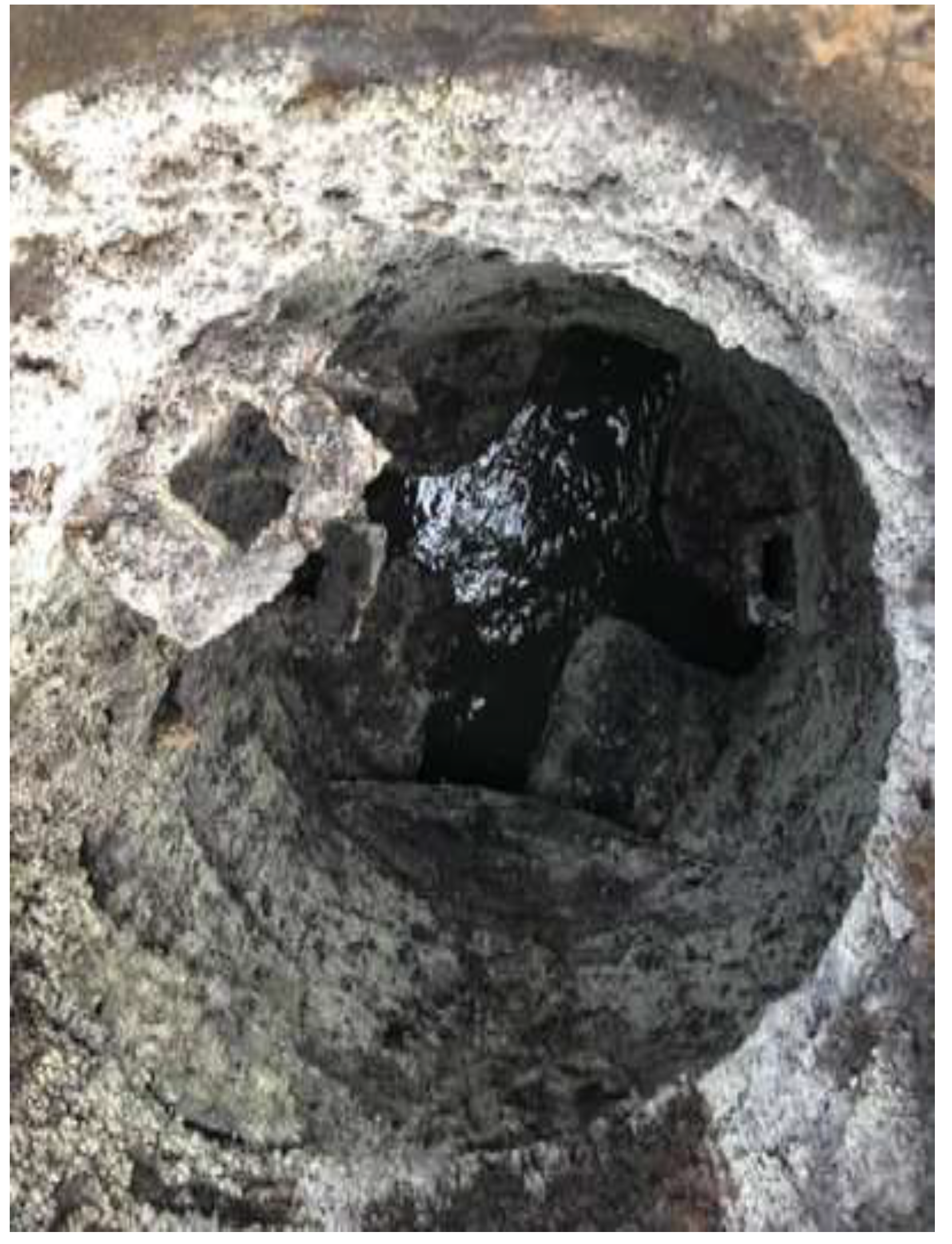
Figure 2.
Renovation method of manholes using construction chemistry.
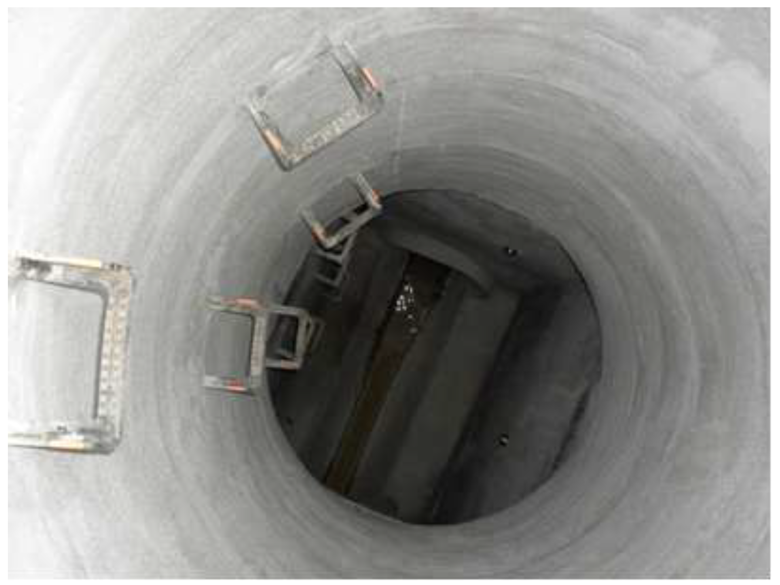
Figure 3.
Renovation method using resins.
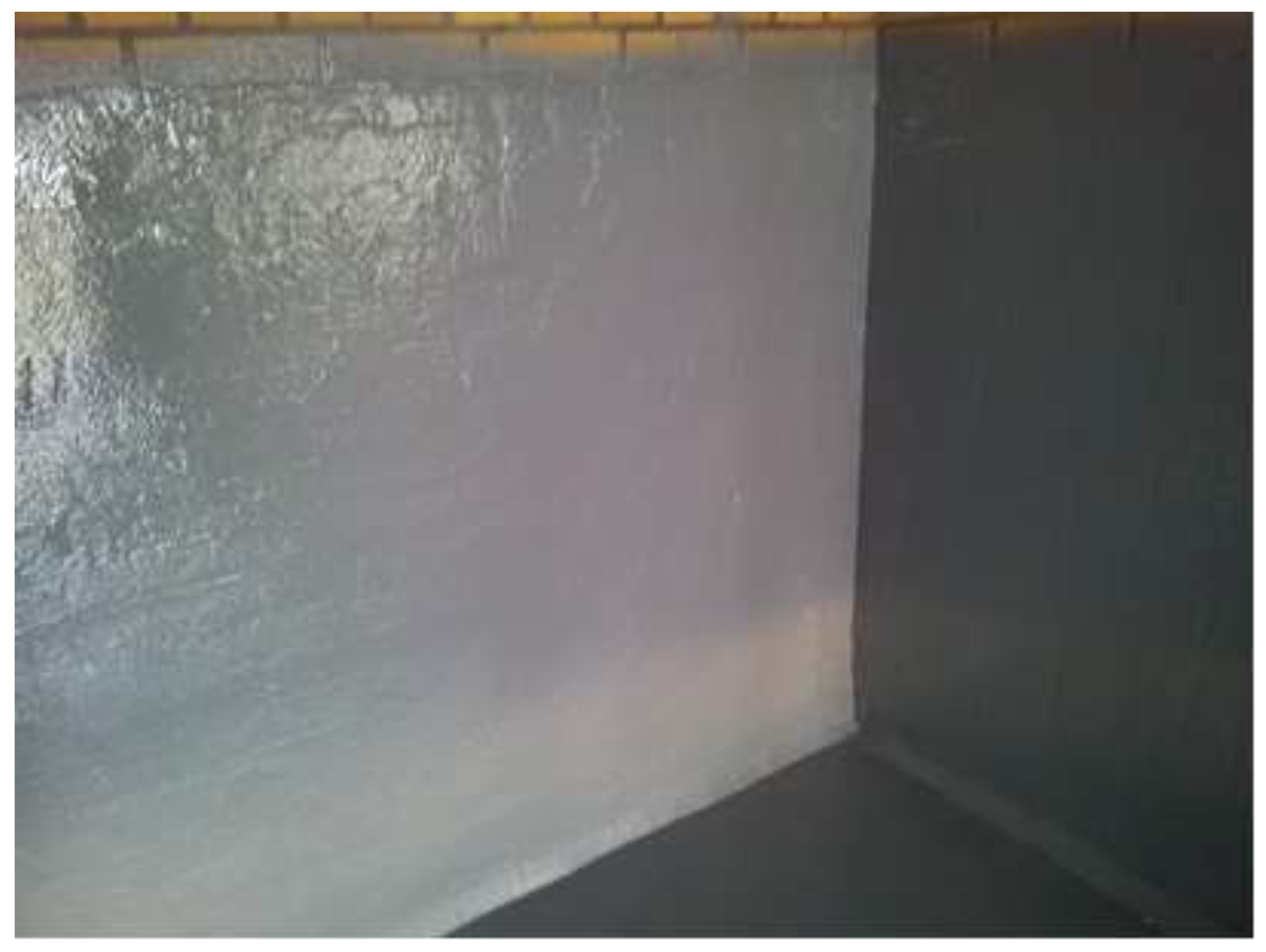
Figure 4.
Renovation method using GRP (TWS) liners.
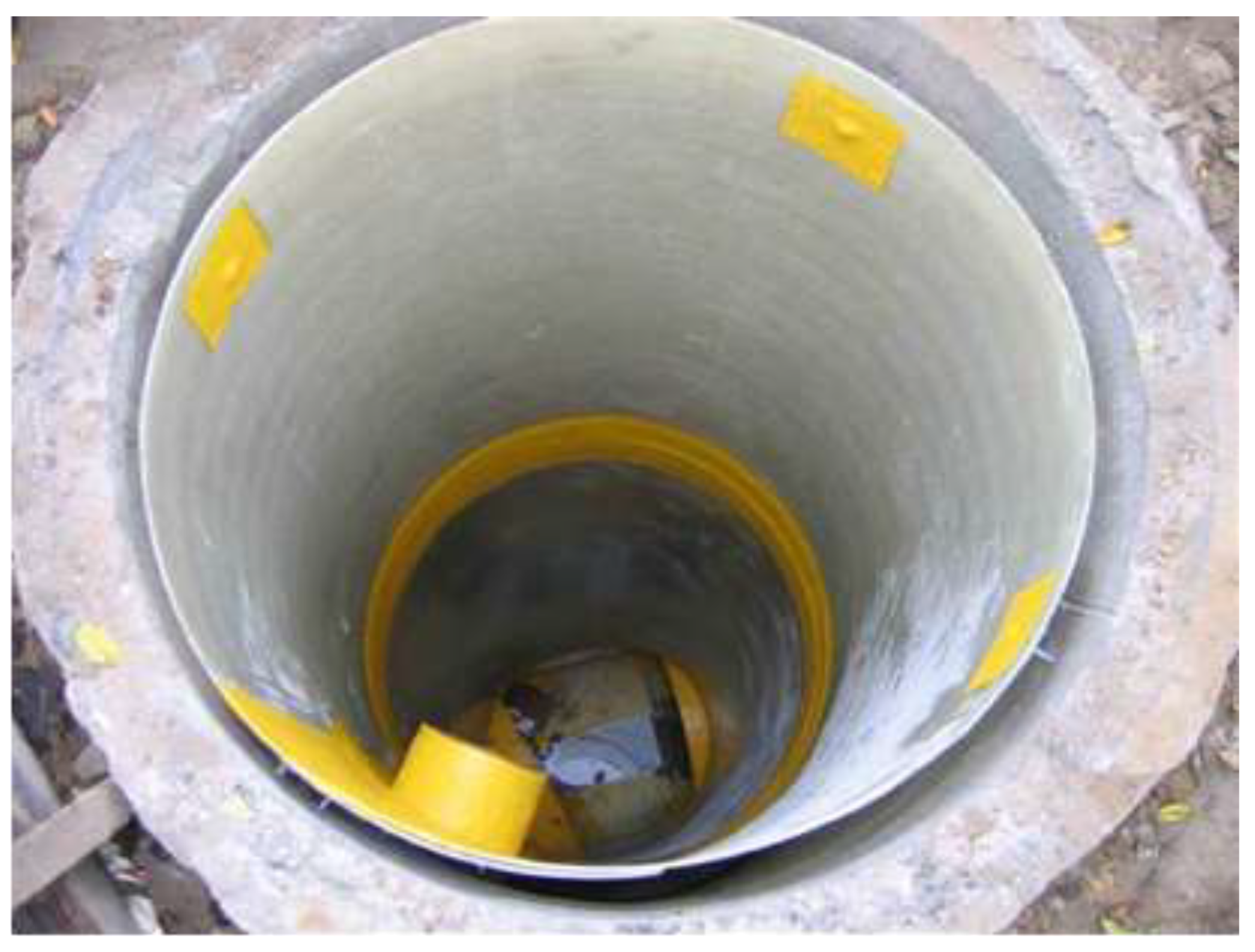
Figure 5.
Renovation method using polymer concrete modules [47].
Figure 5.
Renovation method using polymer concrete modules [47].

Figure 6.
Renovation method using polyurea liners [48].
Figure 6.
Renovation method using polyurea liners [48].
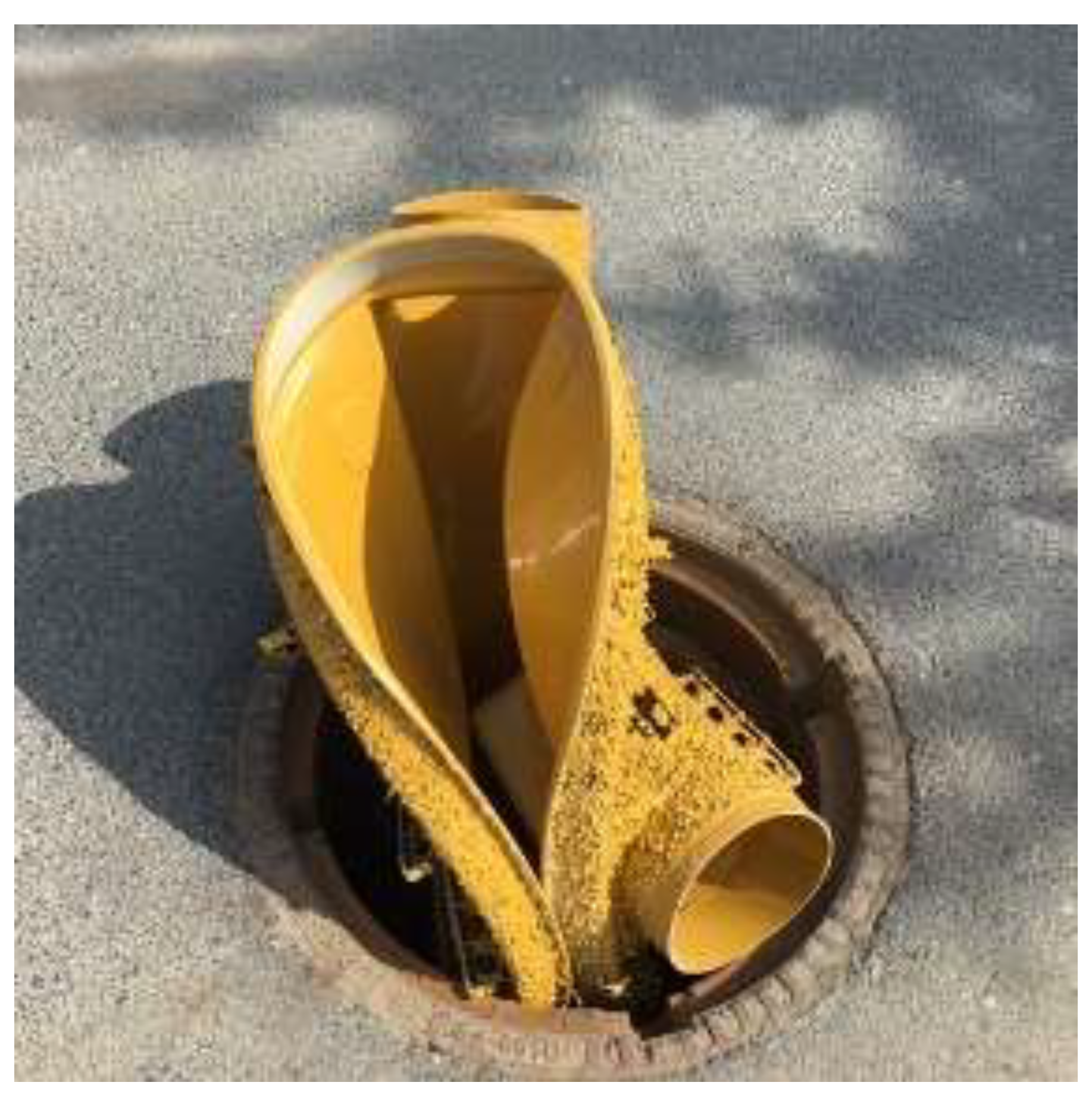
Figure 7.
Restoration of the corroded surface with cement-based materials.
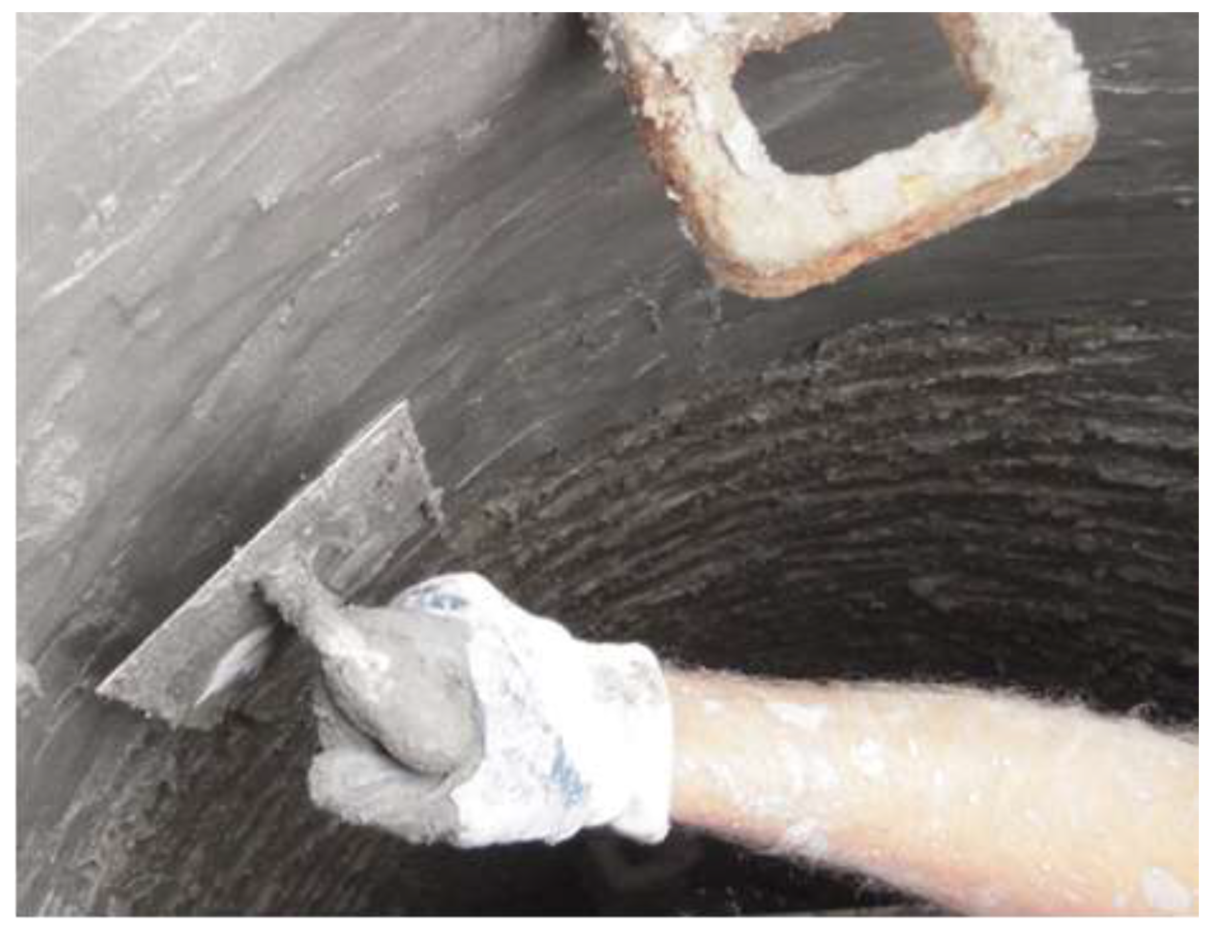
Figure 8.
Hydrodynamic cleaning.
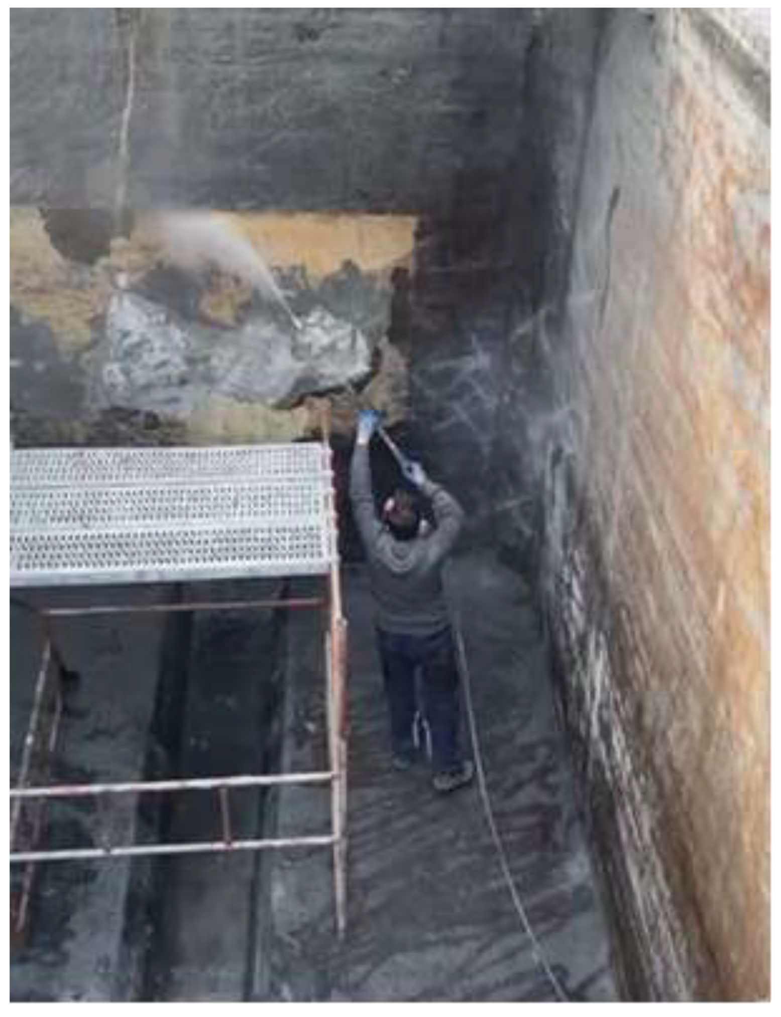
Figure 9.
Pressure injection of cracks.
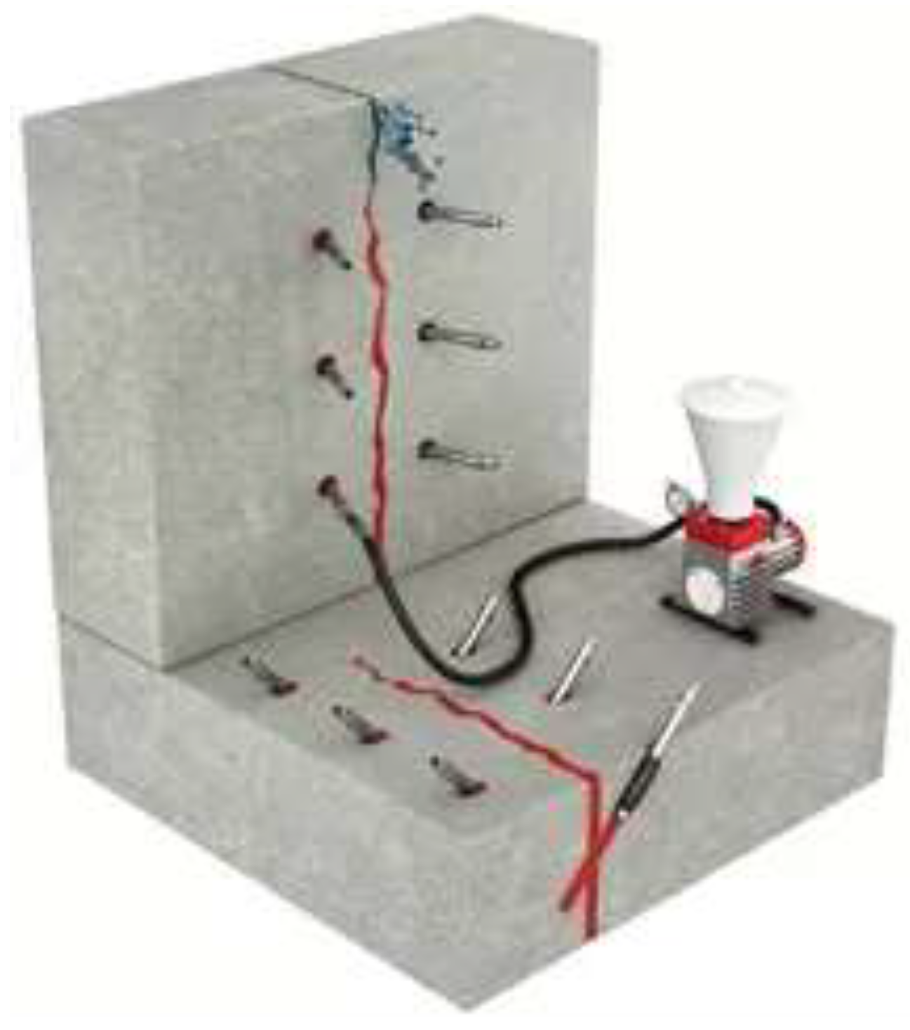
Figure 10.
Base layer of polyurea blocking moisture.
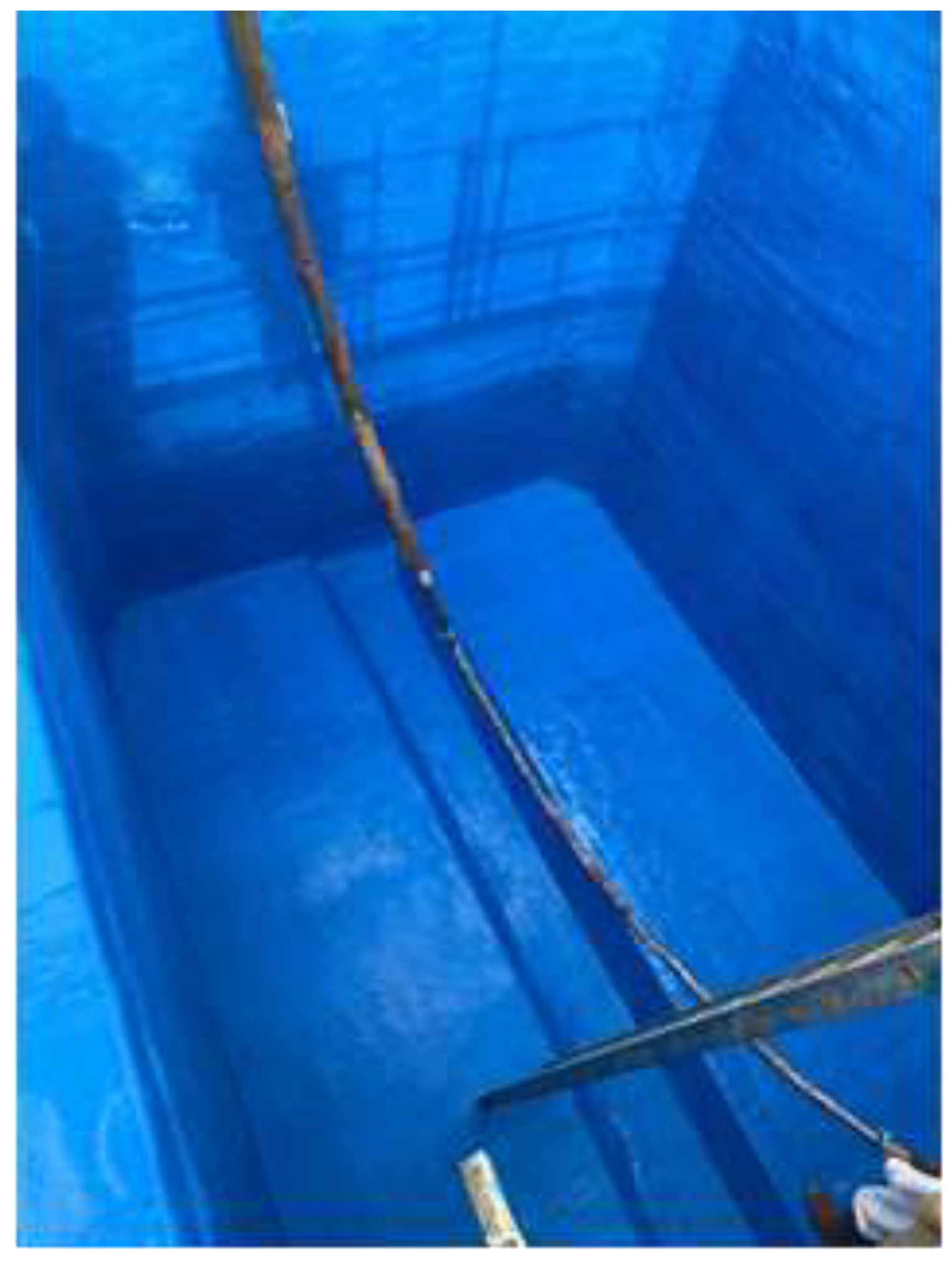
Figure 11.
Repair and reinforcing layer (rigid polyurethane).
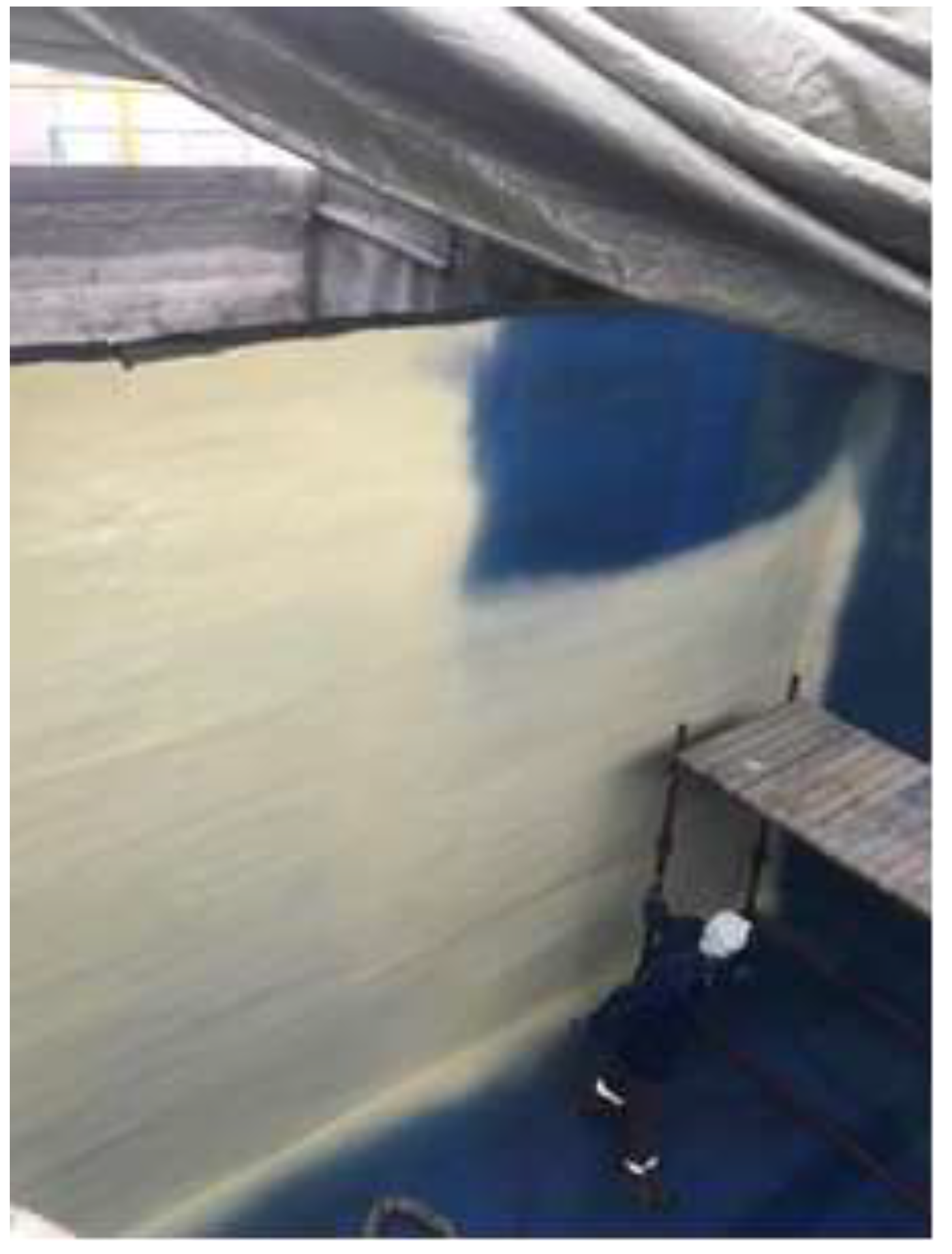
Figure 12.
Final protective layer.
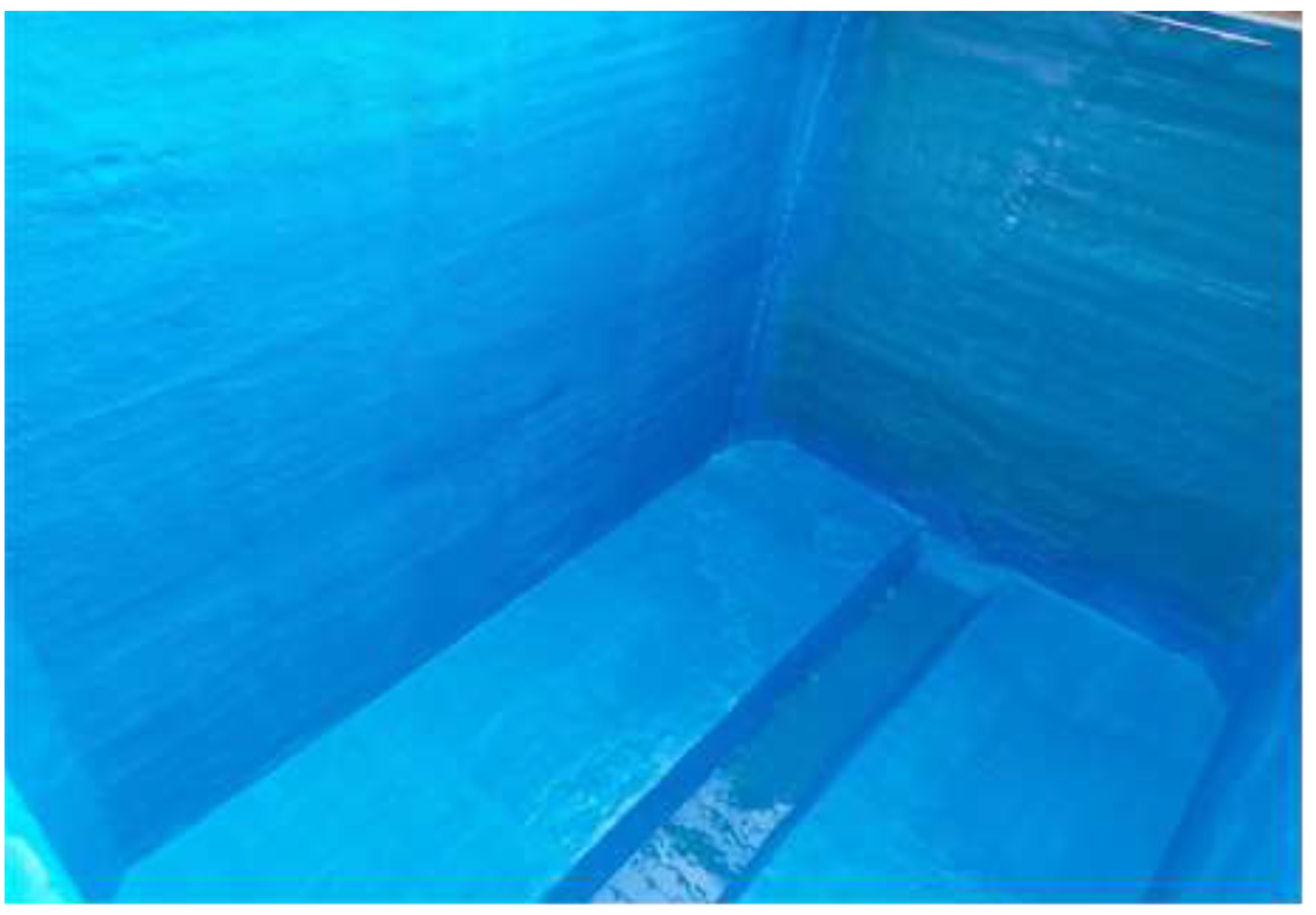

Table 1.
Technical parameters of a sample polyurea membrane:.
| Parameter | Typical Value1 | Method |
|---|---|---|
| Tensile strength | 30 N/mm² | DIN 53504 |
| Elongation at break | 300% | DIN 53504 |
| Tear resistance | 120 N/mm | DIN 53515 |
| Impact resistance | Class III | EN ISO 6272-1 |
| Adhesion to substrate (steel) | >5 MPa | EN ISO 4624 |
| Adhesion to substrate (concrete) | >1.5 MPa | EN 1542 |
| Shore hardness | 60D | EN ISO 868 |
| Abrasion resistance | ≤3000 mg | EN ISO 5470-1 |
| Abrasion | 80 mm³ | DIN 53516 |
1 Typical values can vary depending on specific formulations and conditions.
Table 2.
Comparison of renovation methods using a sewer well as an example.
| No | Renovation method | Cost | Tightness | Resistance to sulfuric acid | Monolithic nature | Layer thickness | Load-bearing improvement |
|---|---|---|---|---|---|---|---|
| 1 | Construction chemicals - polymer-cement mortars | 1 | no | none | none | high | yes |
| 2 | Resins - epoxy/polyurethane | 2 | yes | partial | partial | low | no |
| 3 | GRP (TWS) liners | 2.5 | no | partial | none | medium | yes |
| 4 | Polymer membrane modules | 5 | no | partial | none | high | yes |
| 5 | Polyurea liners | 3 | no | full | none | medium | no |
| 6 | Three-layer membrane | 2 | yes | full | full | high | yes |
Below is a comparative analysis of the various items in the table above.
Table 3.
Stages of work for individual renovation methods for sewer wells along with execution time
| No | Stage I - Cleaning | Stage II | Stage III | Stage IV | Stage V | Stage VI | Total Time |
|---|---|---|---|---|---|---|---|
| 1 | Yes | Application of bonding layer | Application of mortars | Curing | - | - | 14 days |
| 2 | Yes | Application of bonding layer | Application of mortars | Curing | Application of resins | Curing | 16 days |
| 3 | Yes | Installation of GRP liners | Filling the space | Lamination of bottom joints | Curing | - | 10 days |
| 4 | Yes | Removal of cover/neck | Installation of modules | Execution of resin joints | Filling the space | - | 5 days |
| 5 | Yes | Kinetic removal | Kinetic installation | Installation of polyurea liners | Execution of joints | - | 5-6 days |
| 6 | Yes | Drying | Application of 3-layer membrane | - | - | - | 1 |
Disclaimer/Publisher’s Note: The statements, opinions and data contained in all publications are solely those of the individual author(s) and contributor(s) and not of MDPI and/or the editor(s). MDPI and/or the editor(s) disclaim responsibility for any injury to people or property resulting from any ideas, methods, instructions or products referred to in the content. |
© 2024 by the authors. Licensee MDPI, Basel, Switzerland. This article is an open access article distributed under the terms and conditions of the Creative Commons Attribution (CC BY) license (http://creativecommons.org/licenses/by/4.0/).
Copyright: This open access article is published under a Creative Commons CC BY 4.0 license, which permit the free download, distribution, and reuse, provided that the author and preprint are cited in any reuse.


