Submitted:
01 November 2024
Posted:
01 November 2024
You are already at the latest version
Abstract
The application of photopolymerization 3D printing technology in the field of piezoelectric ceramics can achieve high precision, customization, and personalized design of piezoelectric ceramics, providing a better technical means for the fine processing of ceramic materials. We have studied the preparation of PZT piezoelectric ceramic 3D printing slurry, as well as the analysis of forming errors of printed green bodies, debinding process, and sintering. We successfully printed and sintered various porous honeycomb structures of D-type and G-type using a PZT slurry with a solid content of 55 wt.%.
Keywords:
Piezoelectric ceramic
; Photocuring
; 3D printing
; High-performance
; PZT
1. Introduction
Piezoelectric ceramics are functional ceramic materials that can effectively convert mechanical energy into electrical energy and vice versa. Piezoelectric ceramics and their components are core parts of sensors, transducers, and other devices, and their performance directly affects the quality of the device's performance.[1-8] As a functional material, piezoelectric materials have become irreplaceable key materials in fields such as electronic information, healthcare, aerospace, and artificial intelligence. They are widely used in various industries, both military and civilian, with a global market size that has reached tens of billions of dollars per year and is still growing at a compound annual growth rate of over 12%. With the rise of advanced technologies, sensing application devices are becoming lighter, smaller, and more suitable, which also requires piezoelectric functional devices to develop in the direction of integration, lightweight, and intelligence, while also demanding more complex and diverse shapes.[9-11] Therefore, combining 3D printing technology, especially ceramic stereolithography, with the preparation of piezoelectric ceramic materials has become a consensus among researchers in the field of piezoelectric ceramics.
3D Printing Technology, also known as additive manufacturing (AM), rapid prototyping, and formless forming, is a type of rapid prototyping technology. Through 3D printing, it is possible to achieve personalized design of complex structures and step-by-step production of precision parts, greatly shortening the production and research and development cycle. It has the advantages of saving raw materials and not requiring processing molds, which contrasts sharply with traditional manufacturing. New equipment, new technologies, and new materials developed based on 3D printing technology have been applied in industries such as aerospace, biomedicine, automotive parts, building materials, and education, and can greatly reduce their production and R&D costs, accelerating the process of industrial application.[12]
Stereolithography, based on the principle that photosensitive resins undergo polymerization under irradiation with ultraviolet light of specific wavelengths, constructs a three-dimensional solid by layering. Ceramic components prepared using stereolithography technology have the advantages of high precision and excellent mechanical properties, making them particularly suitable for the manufacturing of miniature and high-precision parts. We have researched the preparation of PZT 3D printing slurry and the optimization of printing processes. By utilizing stereolithography technology, we have successfully printed four complex PZT structural green bodies and sintered two types of extremely small surface structures, D-type and G-type.
2. Results and Discussion
2.1. Research on the System and Performance of 3D Printing Slurries
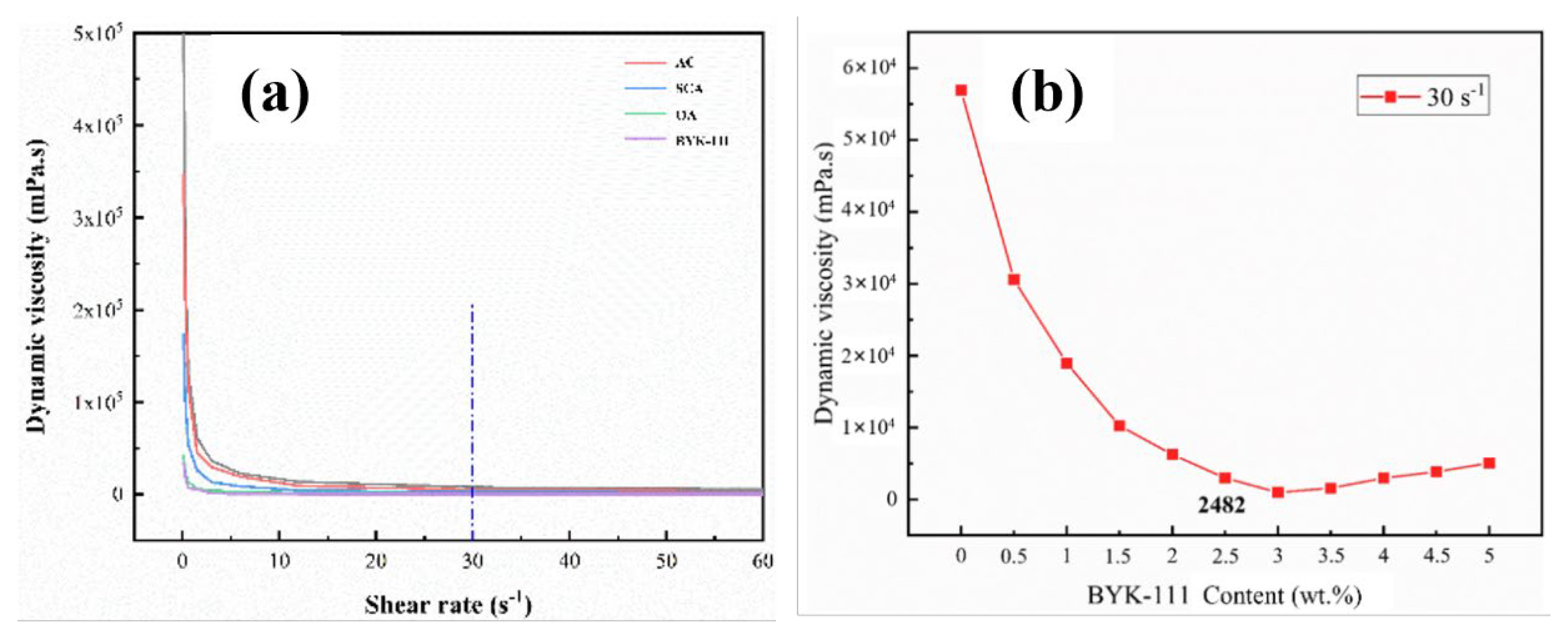
Figure 1 shows the process of preparing ceramic slurry. We studied the effect of the type and content of dispersants on the viscosity and shear rate of the ceramic slurry. Figure 2(a) shows the relationship between viscosity and shear rate for four different dispersants and the slurry without dispersant, which are: ammonium citrate (AC), silane coupling agent (SCA), BYK-111, and oleic acid (OA). All slurries exhibit good shear-thinning behavior, which is a typical rheological characteristic of non-Newtonian fluids, beneficial for the spread of the slurry by the blade during scraping, thus printing a uniformly structured ceramic green body. When the shear rate exceeds a certain value, the viscosity will remain constant. The experimental results show that not all dispersants are usable for reducing the viscosity of the slurry. When AC is used as a dispersant, its slurry viscosity is higher than that of the slurry without dispersant, indicating that AC is not suitable for this resin-based slurry system. The other three dispersants all show good rheological properties, but the viscosity of ideal slurry is ranging from 1000 to 3000 mPa.s (cP) at a shear rate of 30 s-1. BYK-111, the only one, has a viscosity of 2482 mPa.s (cps) at a shear rate of 30 s-1.
The dispersion behavior of ceramics in the slurry is not only related to the type of dispersant but also closely related to the content of the dispersant. Based on the above-mentioned experiments, BYK-111 is selected as the dispersant. It has been verified that the viscosity is optimal (2482 mPa.s) when the content of the dispersant is 2.5 wt.% (Figure 2(b)).
Figure 2.
(a) The viscosity and shear rate variation curves of the slurry prepared with four dispersants and without any dispersant. (b) Viscosity variation curve of the slurry with BYK-111 content at shear rate of 30 s-1.
Figure 2.
(a) The viscosity and shear rate variation curves of the slurry prepared with four dispersants and without any dispersant. (b) Viscosity variation curve of the slurry with BYK-111 content at shear rate of 30 s-1.
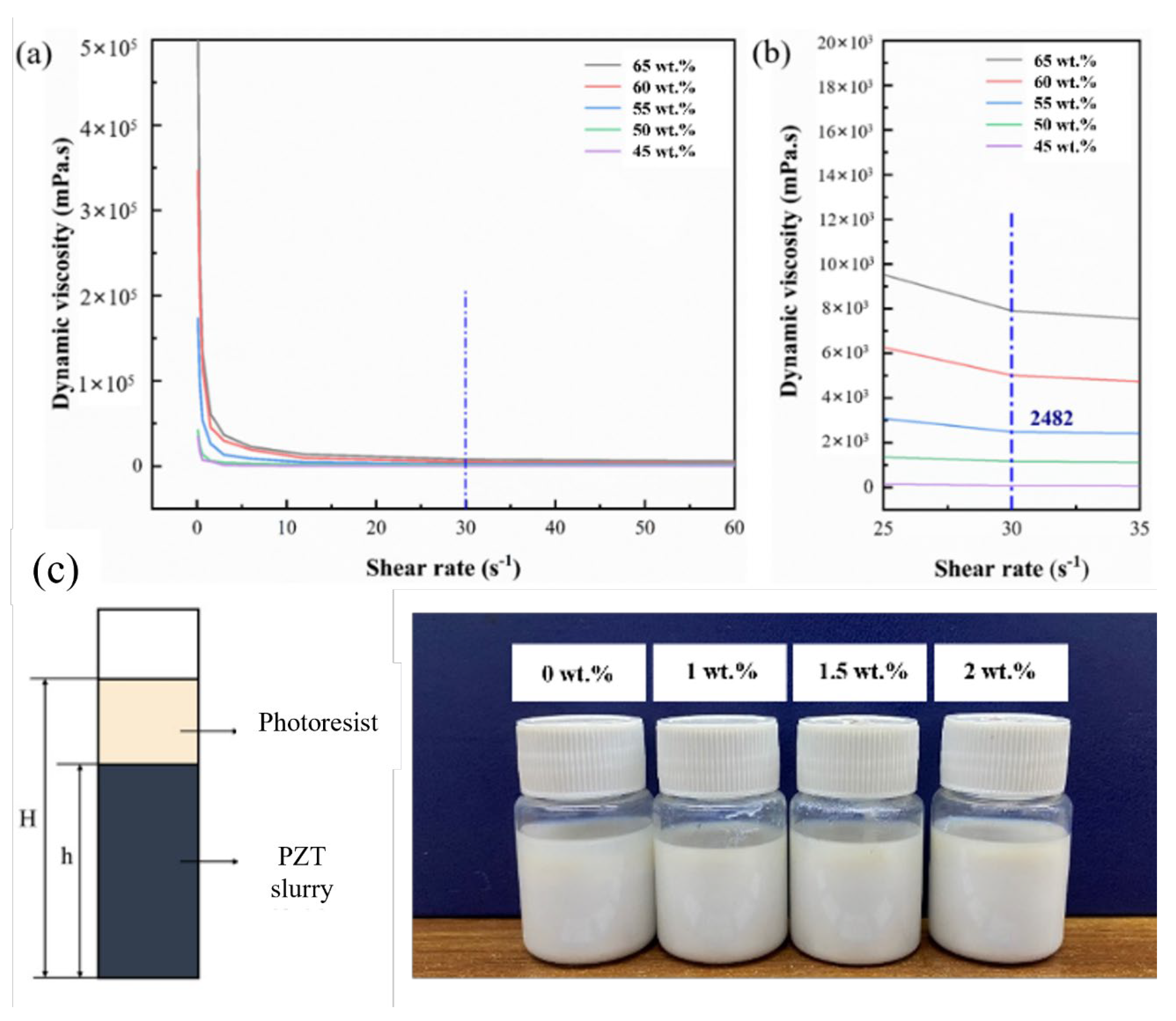
The solid content also has a significant impact on the rheology of the ceramic slurry. Increasing the solid content can effectively reduce the evaporation of organic substances, reduce the porosity of the formed parts during the debinding and sintering process, and obtain a highly dense formed body. In this experiment, 2.5 wt.% BYK-111 is selected as the dispersant to study the viscosity performance of the slurry at different solid contents.
Figure 3(a) represents the change in viscosity of the slurry at different solid contents. With the increase of solid content, the non-Newtonian fluid characteristics of the slurry become more apparent, showing obvious shear-thinning. The viscosity value of the slurry decreases with the increase of shear rate. The interlayer flow of the slurry changes from a three-dimensional structure to a two-dimensional layered structure. The viscosity value gradually decreases, and when the relative flow area between the liquid layers of the slurry is stabilized, the viscosity also tends to stabilize. The viscosity value gradually increases with the increase of solid content. It can be seen from Figure 3(b) that the viscosity value rises when the solid content exceeds 55 wt%. When the solid content is 60 wt.%, the viscosity value exceeds the critical value that suitable for VPP 3D printing, and the viscosity value of the slurry is 5286 mPa.s at a shear rate of 30 s-1. Therefore, we choose a solid content of 55 wt.% as the optimal ratio for the ceramic slurry.
In addition, we studied the effect of adding thickeners on the sedimentation of ceramic slurry. As shown in Figure 3(c), the slurry without thickener began to settle on the third day. The slurry with 1.0 wt.% thickener showed a small amount of sedimentation layering on the 14th day. The slurry with 1.5 wt.% and 2.0 wt.% thickeners did not show obvious sedimentation layering phenomena within 14 days, so the optimal thickener content is determined to be 1.5 wt.%.
Figure 3.
The viscosity curves of PZT slurry at different solid contents. (b) The viscosity value at a shear rate of 30 s-1. (c) The effect of different thickener contents on the sedimentation variation of the slurry.
Figure 3.
The viscosity curves of PZT slurry at different solid contents. (b) The viscosity value at a shear rate of 30 s-1. (c) The effect of different thickener contents on the sedimentation variation of the slurry.
2.2. Fabrication of Piezoelectric Ceramic 3D Printing Green Bodies
Photocurable resin ceramic slurries with photocuring characteristics can be applied to additive manufacturing, because the photoinitiator in the ceramic slurry decomposes to produce cationic groups or free radicals under the irradiation of ultraviolet light or visible light. The free radicals produced by the decomposition activate the reactive diluents and undergo rapid polymerization reactions with the unsaturated carbon-carbon double bonds in the resin, forming a cross-linked network. The single chains turn into a network of polymers, forming a high molecular weight solidification product, and encapsulating the ceramic powder within it to form a ceramic green body.[13] The principle of digital light processing technology is shown in Figure 4.
2.3. Analysis and Optimization of Forming Errors in the Preparation of Printed Green Bodies
Scattering and transmission during the printing process can have a certain impact on the forming. Figure 5(a) shows the severe defects that occur on the printing plane when scattering is significant. The scattering-induced forming errors can be mitigated by reducing the exposure light intensity and increasing the exposure time during the printing process. The transmission phenomenon mainly affects the precision in the z-axis direction when printing overhanging structures, as shown in Figure 5(b). The printed conical pores, influenced by the light transmission, will have some excess forming parts, showing a layered step effect, which reduces the printing precision. In the actual printing process, the printing precision can be improved by reducing the single-layer printing thickness and setting the z-axis contraction compensation value. The reasonable range for the single-layer thickness should be between 20~50 μm.
For the prepared ceramic slurry, its stability and purity may decrease over time during the printing process, which is specifically manifested as the formation of residue and agglomerates within the slurry. Impurities within the slurry will adhere to the blade, affecting the normal spreading of material, causing strip-like gaps on the material disk, and affecting the final forming quality. Additionally, the presence of these impurities will also affect the final precision. Therefore, the prepared slurry should be stored away from light to avoid forming errors caused by slurry deterioration. After storing for a period, the slurry should be ball-milled to well dispersed. The impurities in the slurry should be promptly disposed and the residue should be cleaned out in a timely manner to ensure the quality of the printed green bodies.[14] Based on the above-mentioned analysis, four different complex green bodies were printed, as shown in Figure 6.
2.4. Research on the Debinding Process of 3D Printed Piezoelectric Ceramic Green Bodies
The green body formed by photocuring 3D printing processes contains a large amount of organic substances (45 wt.%), such as resins and additives. Therefore, a debinding process is required before sintering. The debinding process is generally carried out in a vacuum or inert gas environment, where the organic substances undergo a decomposition reaction similar to dry distillation, releasing small molecule gases and liquids, and leaving carbon on the surface of the green body.[15] It is beneficial for slowing down the defects caused by oxidation reactions and maintaining the original shape of the part. Subsequent carbon removal treatment is necessary. Therefore, 3D printed PZT piezoelectric ceramics generally need to go through a three-step heat treatment process of debinding-decarbonization-sintering (Figure 7(a)).
High-quality debound samples can be obtained by optimizing the sintering conditions, including adjust the heating rate, use bottom powder assistance for debinding, use porous blocks, and different sintering atmospheres. Figure 7(b-e) shows the debound samples after different treatment methods. The conclusion was that a heating rate of 0.33 ℃/min, with the assistance of porous blocks, and debinding in an Ar gas environment, can effectively reduce the breakage and bending phenomena during the sintering process.
2.5. Sintering of Piezoelectric Ceramic 3D Printing Green Bodies
After debinding, the printed ceramic green bodies are densified through traditional sintering processes. The sintering method involves spreading PBZTN-0.1Fe powder at the bottom of the crucible, placing the debound samples, and then covering them with a mixture of zirconia/PSZTN-0.1Fe (in small amounts) to prevent element volatilization and powder adhesion. High-temperature muffle furnaces are used for sintering.
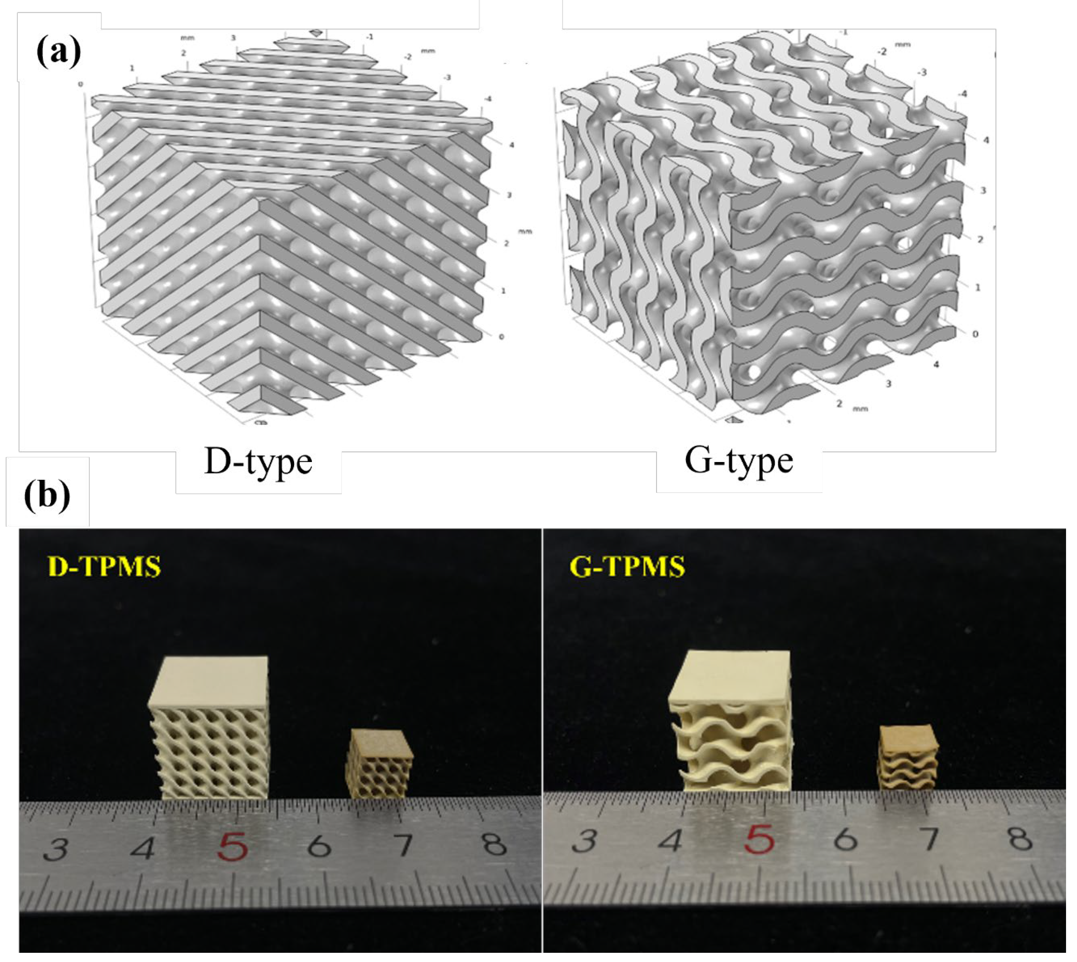
In this experiment, three representative minimal surface structures were selected, namely the Diamond structure (D-type), Gyroid structure (G-type), and Schwartz P structure (P-type), as shown in Figure 8(a). The modeling software, Creo, was used for modeling, and three minimal surface structures were designed, with specific design information. Ultimately, the D-type and G-type structures were selected as the target printed configurations.
Based on the processes and structural design methods, D-type and G-type porous honeycomb structures as shown in Figures 7(b) were successfully fabricated using a PZT slurry with a solid content of 55 wt.% and then sintered. The final sintered samples maintained their original morphological structure. This demonstrates the unique advantage of additive manufacturing in the rapid fabrication of complex structures and proves the feasibility of digital light curing technology for the preparation of high-precision, high-complexity ceramic materials. [16-17]
3. Summary
We have successfully developed a PZT slurry for 3D printing and used photocuring technology to print four complex structures, analyzing the causes of forming errors during the printing process. We studied the debinding process of 3D printed PZT piezoelectric ceramic green bodies and performed sintering to obtain high-quality sintered products with D-type and G-type minimal surface structures. Our research provides data and model support for the field of piezoelectric ceramic 3D printing, offering broader prospects for the potential application of piezoelectric ceramics.
References
- 2003; 1. 陈光, 新材料概论, 科学出版社, 2003 年.
- R. E. Newnham, D. P. Skinner, L. E. Cross, Connectivity and Piezoelectric-Pyroelectric Composites, Mater. Res. Bull., 1978 (13): 525-536. [CrossRef]
- C. Zhang, The development of piezoelectric materials and its applications, Piezoelectric and Acoustic optics, 1993 (15): 64-70.
- G. G. John, A. K. John, et al., Piezoelectric materials for acoustic wave applications, IEEE Trans UFFC, 1994 (41): 53-59. [CrossRef]
- W. A. Smith et al., The application of 1-3 piezocomposites in acoustic transducers, Proceedings of 7th International Sympl. Appl. Ferro., 1990: 145-152.
- T. R. Gururaja, W. A. Schulze, et al., Evaluation of Ultrasonic medical application. IEEE Trans. Sonics Ultrason., 1985 (511): 499-513. [CrossRef]
- IEEE Standard on piezoelectricity, IEEE T Ultrason Ferr, 1996 (43): A1-A54.
- Cross L E. Relaxor ferroelectrics: An Overview[J]. Ferroelectrics, 1994,151(1): 305-320. [CrossRef]
- Yoon C B, Lee S M, Lee S H, Kim H E. PZN-PZT Flextensional Actuator by Co-extrusion Process. Sensor Actuat a-Phys, 2005, 119(1): 221-227. [CrossRef]
- 侯育冬, 高峰, 朱满康, 王波, 田长生, 严辉. 压电变压器用陶瓷材料的成分设计[J]. 电 子 元 件 与 材 料, 2003, 22(11): 16-20.
- Lee S M, Park C S, Kim H E, Lee K W. Helical-shaped Piezoelectric Motor using Thermoplastic Co-extrusion Process[J]. Sensor Actuat a-Phys, 2010, 158(2): 294-299. [CrossRef]
- Chu Wei, Tan Yuanxin, Wang Peng et al., Centimeter-scale superfine three-dimensional printing with femtosecond laser two-photon polymerization, arXiv:1802.01650.
- Liu Chun-Lei, Du Quanpei, Zhou Han et al., 3D printing of lead zirconate titanate piezoelectric ceramics via digital light processing (DLP), Ceramics International, 2023, 49(17): 28492-28499. [CrossRef]
- Kim Insup, Andreu Alberto, Yoon Yoon-Jin, A digital light processing 3D printing approach for tuning the interfacial properties of pore forming agents for porous ceramics, Materials & Design, 2023, 233: 112247. [CrossRef]
- Chen Zhangwei, Li Ziyong, Li Junjie et al., 3D printing of ceramics: A review, J Euro Ceram Soc, 2019, 39: 661-687. [CrossRef]
- Bowen, C. R, Kim, H. A, Weaver, P. M et al. Piezoelectric and ferroelectric materials and structures for energy harvesting applications, Energy & Environmental Science, 2014, 7(1): 25-44. [CrossRef]
- Salazar, R, Serrano, M, Abdelkefi, Fatigue in piezoelectric ceramic vibrational energy harvesting: A review, Applied Energy, 2020, 270: 115161. [CrossRef]
Figure 1.
Flowchart of PZT ceramic slurry preparation process.
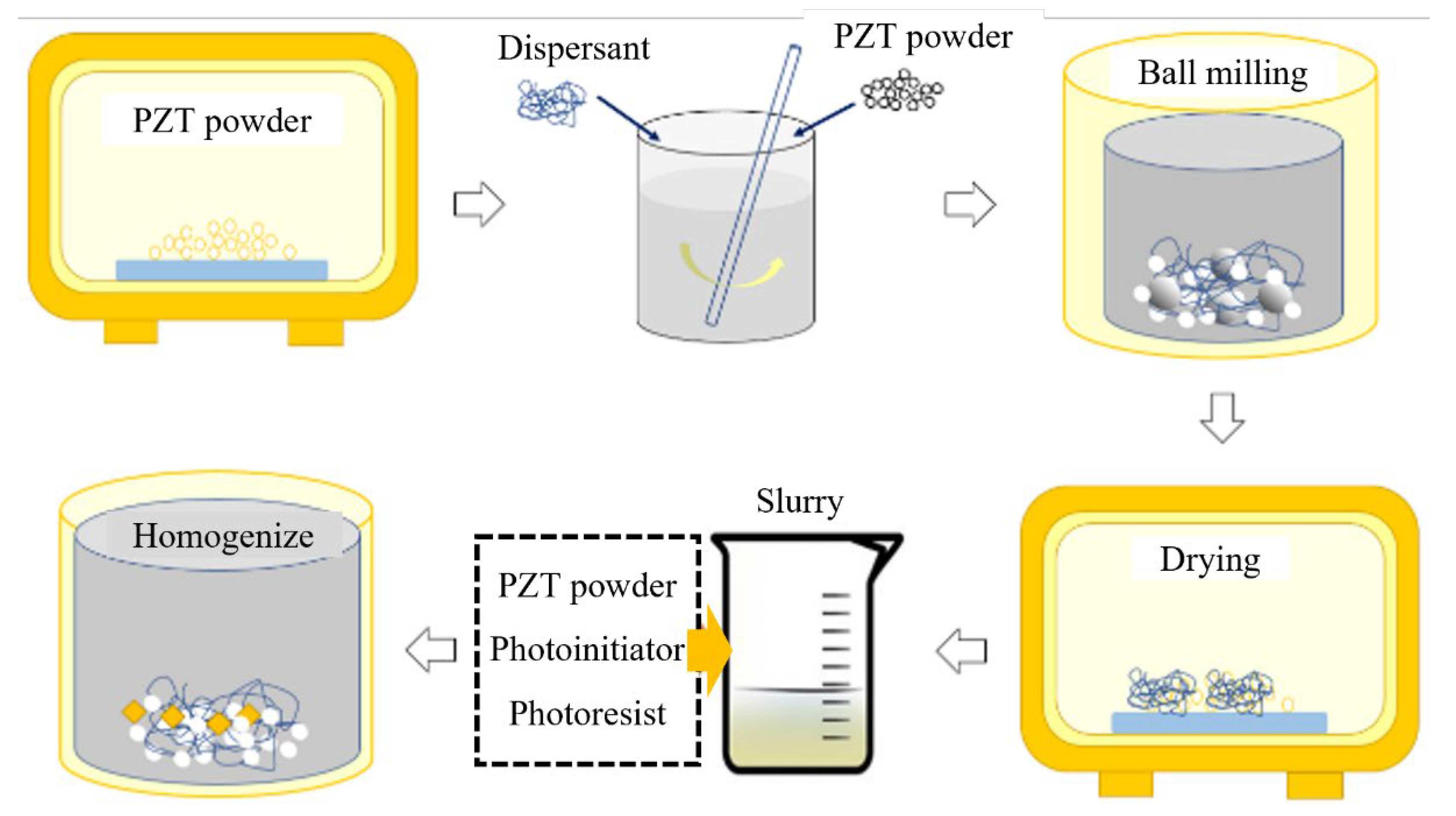
Figure 4.
(a) Schematic of digital light processing (DLP) technology.
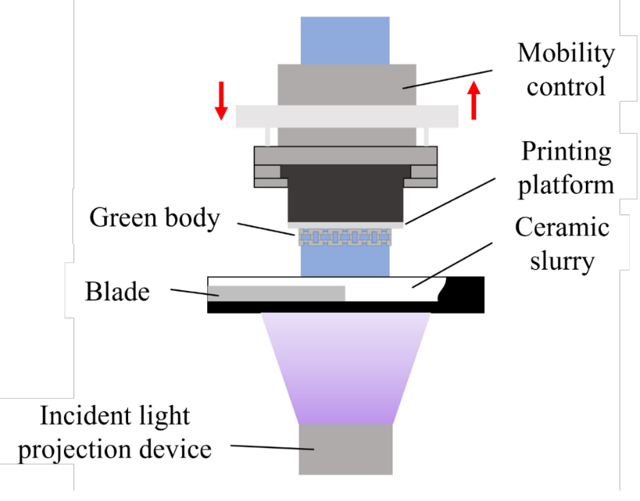
Figure 5.
Defect types of printed green bodies: (b) scattering; (c) transmission.
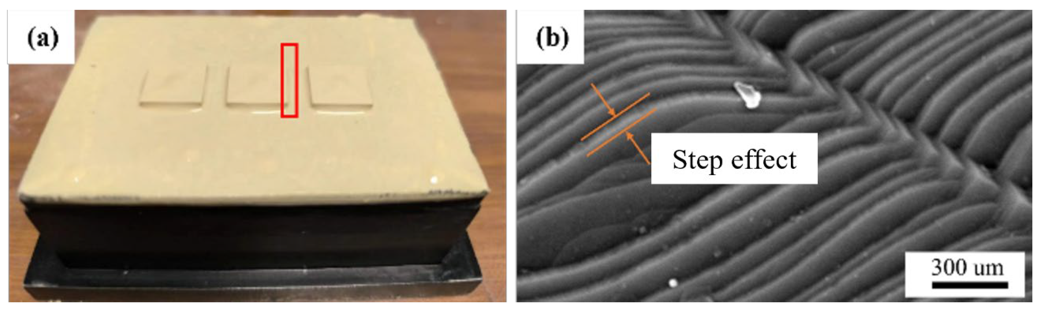
Figure 6.
Printed PZT green bodies with complex structures.
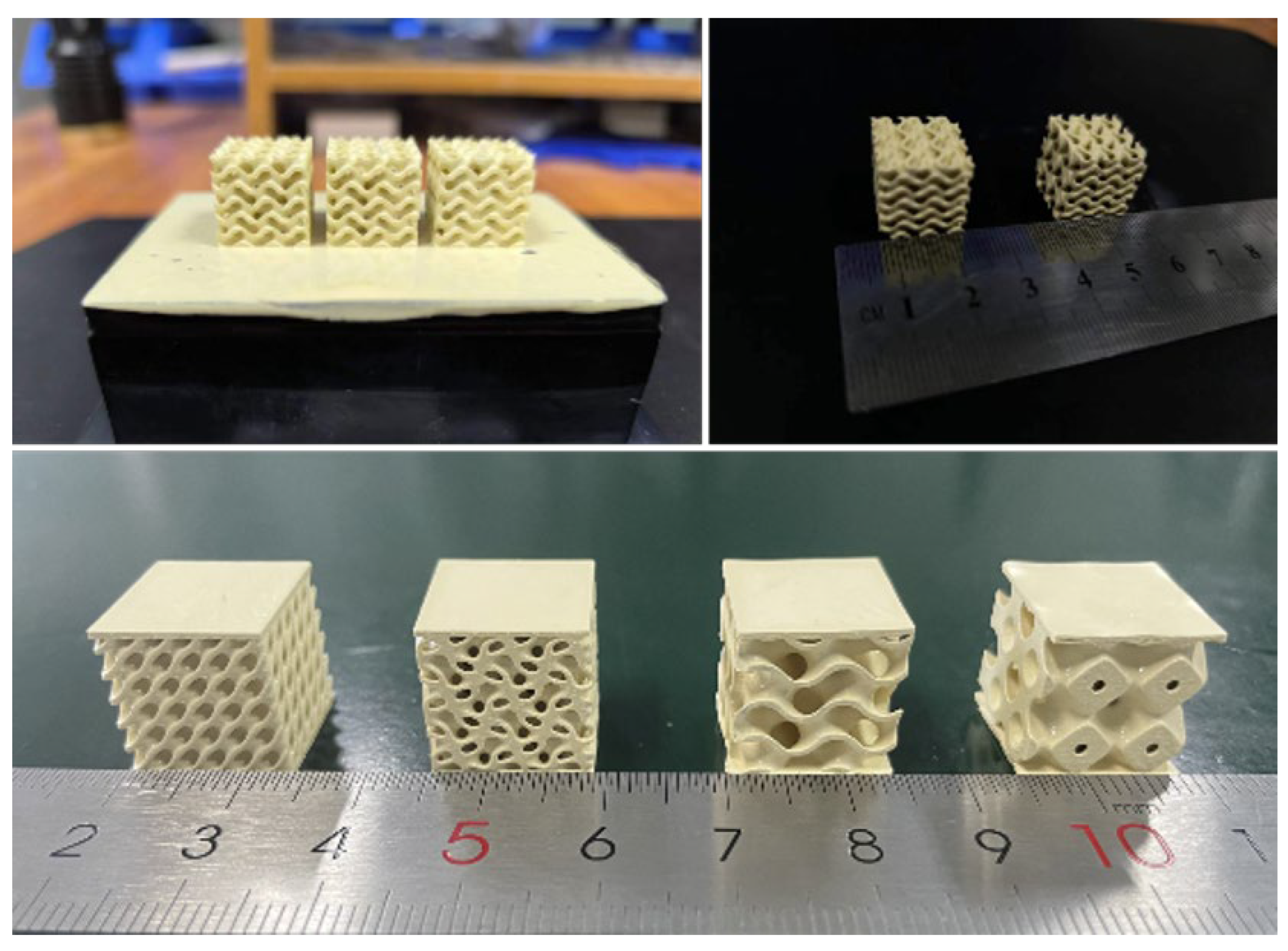
Figure 7.
The debinding processes (a) Three-step heat treatment process of debinding-decarbonization-sintering for 3D printed PZT piezoelectric ceramics. (b) Before and after debinging at heating of rate of 1 ℃/min in air without supporting materials. (c) Before and after debinding with supporting powders. (d) Before and aftering debinding with porous blocks. (e) Before and after debinding in different atmosphere: air, vacuum and Ar. The black color was caused by the carbon residue, which can be removed by the second debinding in air. All the samples in yellow rectangle is before debingding, blue is after debingding.
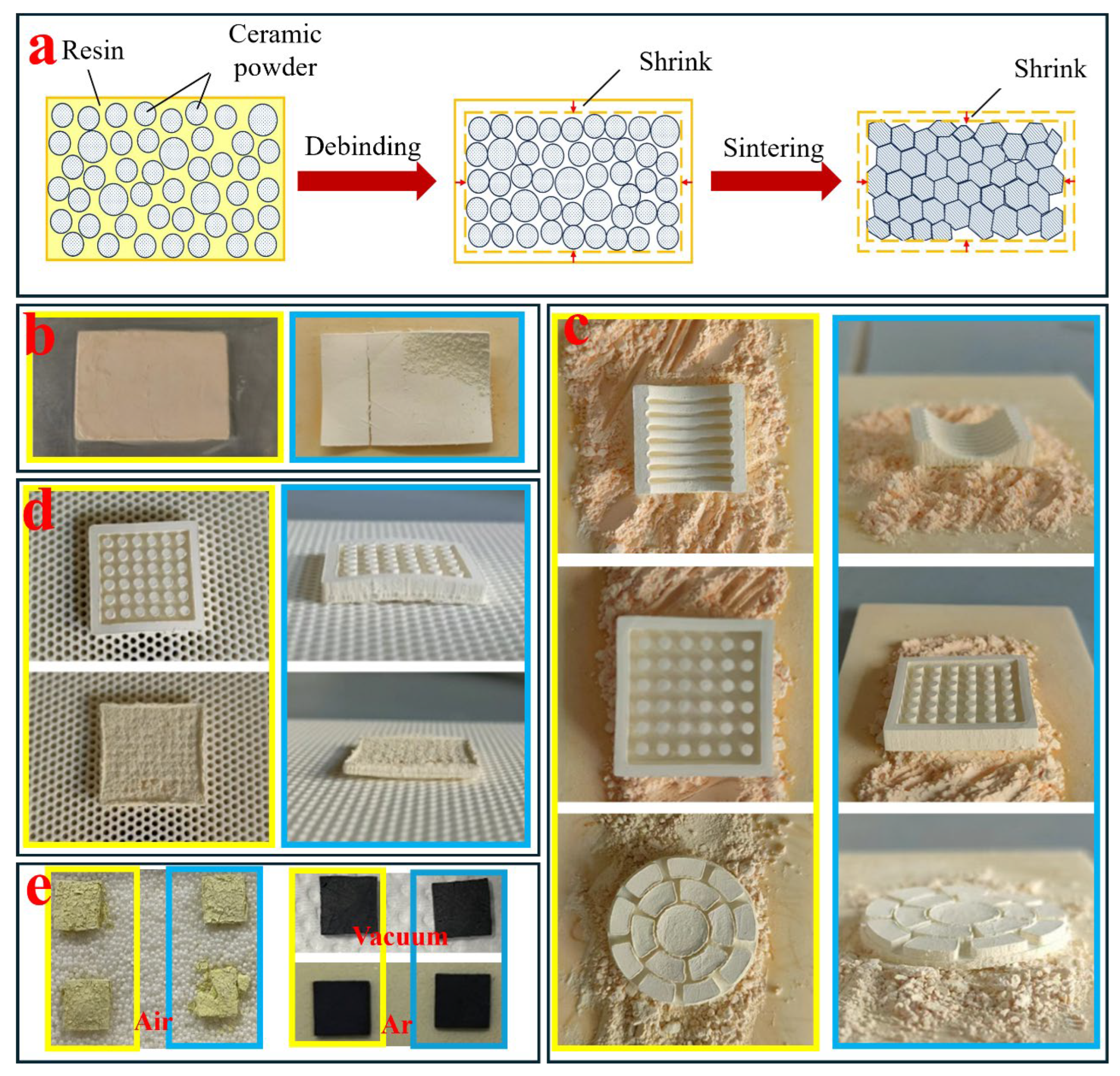
Figure 8.
D-type and G-type minimal surface structures (a) model structures, (b) sintered structures.
Figure 8.
D-type and G-type minimal surface structures (a) model structures, (b) sintered structures.
Disclaimer/Publisher’s Note: The statements, opinions and data contained in all publications are solely those of the individual author(s) and contributor(s) and not of MDPI and/or the editor(s). MDPI and/or the editor(s) disclaim responsibility for any injury to people or property resulting from any ideas, methods, instructions or products referred to in the content. |
© 2024 by the authors. Licensee MDPI, Basel, Switzerland. This article is an open access article distributed under the terms and conditions of the Creative Commons Attribution (CC BY) license (http://creativecommons.org/licenses/by/4.0/).
Copyright: This open access article is published under a Creative Commons CC BY 4.0 license, which permit the free download, distribution, and reuse, provided that the author and preprint are cited in any reuse.


