
Submitted:
28 October 2024
Posted:
30 October 2024
You are already at the latest version
Abstract
This paper proposes a new type of solar trough collector with cylindrical mirror spliced and develops a new ray tracing method to predict and optimize its performance. The mirrors of this system are composed of multiple cylindrical mirrors whose centres are on a parabola and the normal vector of the centers of each cylindrical mirror is consistent with the normal vector of the parabola point where it is located. This paper compares the cylindrical mirror spliced trough solar system with the conventional parabolic trough system and finds that the influence of cylindrical spherical and coma aberration can be reduced to negligible levels by adjusting the system design. At the same time, the slope error and cost of the cylindrical mirror is much less than the parabolic mirror so it has better performance from numerical simulation. On the vernal equinox, the net efficiency of the cylindrical mirror spliced system using a cavity receiver is 22.39% higher than that of the conventional trough system using vacuum tube receiver. The cylindrical mirror spliced system can be further optimized to achieve an annual net efficiency of 60.2% in the north-south horizontal axis tracking mode.
Keywords:
spliced cylindrical mirror
; trough solar system
; concentration ratio
; solar energy
; spherical aberration
1. Introduction
In recent years, solar energy has emerged as the fastest-growing renewable energy technology[1].A common method of utilizing solar energy is through solar thermal concentration systems, which convert solar energy into thermal energy. These systems can be classified based on their focusing method into point-focusing systems (tower systems and dish systems) and line-focusing systems (parabolic trough systems and linear Fresnel systems)[2].The parabolic trough solar thermal power generation system is currently one of the most prominent solar thermal power systems. This technology is the most commercially mature, and has been tested in a variety of practical situations and is also the most widely used[3,4].
The line-focusing trough solar energy system mainly includes a tracking system, receiver and reflector. There are two types of tracking systems: Dual-Axis Tracking System (DAT) and Single-Axis Tracking System (SAT). The single-axis tracking system can be further divided into the North-South tracking system (NS), East-West tracking system (EW) and polar tracking system based on the position of the rotation axis[5].Early trough systems used flat receivers, which had a low concentration ratio and were later replaced by tube receivers[6]. The reflector typically employs a parabolic trough mirror, which efficiently reflects and concentrates the solar radiation towards the receiver. However, the trough reflectors are challenging to manufacture, often resulting in significant slope errors in the mirror surface. Therefore, it is possible to consider using spliced cylindrical mirrors instead of complete trough mirrors, which can reduce the process difficulty of manufacturing and reduce the mirror slope errors.
Solar trough collector systems with cylindrical trough collectors have been studied for a long time. Hassan and Refaie [7]studies examined cylindrical parabolic solar collector defining their ideal performance as a benchmark for intermediate-temperature reflectors. It identified optimal target widths for maximizing the energy concentration in different solar collector configurations, observing a continuous energy increase for the backside solar collector. Evans[8]provided an integral expression to calculate the concentration ratios of flat receivers with cylindrical parabolic solar collectors by incorporating rim angles, solar models, and mirror reflectivity. Ruben[9]compared five line-focusing solar trough collectors and found that the cylindrical-parabolic solar collector attained the best-focusing factor. Further studies of Ruben evaluated four solar-disk models (square, uniform, real, and Gaussian) and found that the real model was the most accurate, significant differences in local concentration factors appeared only when solar concentrator imperfections were small and non-concentrators were also considered, for practical applications, all models were sufficient for concentration calculations with typical imperfections, but precise local calculations required careful model selection[10] Nijegorodov[11]presented an optimized design for cylindrical solar collector, designed at a rim angle of 45°which offered a good balance between cost, performance, less sensitivity to solar ray deviations and provided consistent efficiency for thermal application. Other focusing solar collectors, such as the dish solar concentrators, use segmented mirrors instead of complete mirrors. Previously, we proposed a novel composite dish concentrator comprising 249 spherical mirrors with a concentration ratio of approximately 2000, which achieved a net thermal efficiency of 85.87% and an intercept factor of 98.60%[12].
In 2003, the Australian National University (ANU) proposed a dish concentrator that employed an array of equilateral triangular spherical mirrors, the 400 m² composite spherical mirrors were configured in a parabolic shape to assess their optical performance, feasibility in paraboloidal dish concentrators and compared with conventional multi-facet solar collectors. The study suggested that utilizing identical spherical reflector sub-components oriented paraboloidal on a space frame structure could simplify the manufacturing process and lower the costs, with optical performance similar to traditional designs, while simplifying mirror panel production[13]. Australian National University subsequently designed and built a 500m² composite dish solar system with 390 spherical mirrors, each measuring 1.17 m × 1.17 m[14].
Furthermore, Liu[15] in 2012 proposed a dish solar collector as a model for a parabolic surface using square flat facets supported by a parabolic frame, optimized it to achieve specific flux characteristics at the focal plane through Monte Carlo ray-tracing analysis. Key findings included the design and optimization of a 164-facet concentrator delivering up to 8.15 kW of radiative power over a 15 cm radius disk, achieving an average concentration ratio exceeding 100. This design offered a cost-effective alternative to traditional parabolic dish concentrators for industrial applications. When employing circular mirrors such as cylindrical mirrors as replacements for parabolic mirrors, the critical issue to address is the spherical aberration, for example of a circular mirror because of its constant curvature that is , light rays hitting different parts of the mirror do not focus at the same point, rays converge on the focal plane instead of the focal line resulting in aberration. Aberration theory states that, in Kleopalova’s "Research and Inspection of Optical Systems" page 175[16], the relative aperture of a spherical reflector as the primary mirror should not exceed 1:10.8 that means, the ratio of the reflector aperture to the focal length is ⩽1/10.8 which is then converted to the ratio of the reflector aperture to the spherical radius ⩽1/21.6. In the field of solar energy concentration, optical systems are mainly used for concentration and the requirements are much lower than those for optical imaging.
The receiver is one of the most critical components of a parabolic trough concentrator. When optimizing a parabolic trough solar collector, one of the essential parameters of the receiver is the concentration ratio (CR) defined as the ratio of the area of the light collection region to the location of the light absorption region[17]and also the concentration ratio is inversely related to the efficiency loss caused by thermal losses[18].The relatively high concentration ratio design allows the parabolic trough system to operate at a higher temperature. Since the heat loss per unit area of the receiver is large, and the tube receiver has a large heat dissipation area and a low concentration ratio, the efficiency loss caused by heat loss is large. Compared with traditional receivers, cavity receivers have lower heat loss and higher efficiency and can operate at higher temperatures, improving the efficiency of the thermoelectric system and the overall system efficiency [19,20]. The main methods for analyzing and optimizing trough solar collectors include the cone optics method [21,22,23], the ray tracing method[24,25] and the semi-infinite method [26]. The cone optics method treats the sunlight beam as a cone with the incident point as the vertex and to calculate the energy absorbed at each point on the receiver, the entire surface of the reflector must be integrated. The semi-infinite method has accurate physical characteristics, but due to its complex formulas, it still requires a large amount of computation. The ray tracing method is a widely used microscopic approach that is easy to code, but because it involves the calculation of a large number of rays, it brings a significant computational burden. This method simulates the process of sunlight being incident on the solar collector and then reflected onto the receiver, with each ray representing a portion of the energy incident on the receiver [24,27]. Daly proposed a reverse ray tracing method to calculate the performance of parabolic trough systems [24], which was later improved by several researchers. Grena developed a three-dimensional model based on a recursive ray tracing algorithm [27]. Jiang and others proposed a parabolic trough hybrid photovoltaic/thermal system and used the ray tracing method to establish a three-dimensional optical model for the system [25]. Zou and others considered the impact of ray escape on parabolic trough systems, studying the system using the Monte Carlo ray tracing method and theoretical analysis [28]. Houcine[29] proposed a detailed calculation method based on ray tracing, called Ray Tracing 3Dimensions-4Rays (RT3D-4R) and studied the total intercepted solar energy and daily solar gain for parabolic trough solar collector systems under different concentration ratios and rim angles, using different tracking systems. One of the main drawbacks of the traditional ray tracing method is the large computational demand, making it difficult to use for performance optimization analysis.
This paper proposes a new cylindrical mirror spliced trough solar thermal collection system, which is similar to the conventional trough solar system, but uses multiple cylindrical mirrors to form a reflector to simulate a parabolic reflector. This paper also proposes a new line focusing system ray tracing method that can be used to calculate the performance of various line focusing solar systems. We use this model to analyze the performance of the cylindrical spliced solar system, including the performance under different error conditions and propose an optimized design. We also combine the trough reflector and the cylindrical mirror spliced reflector with the cavity receiver and the tube receiver, respectively, we calculate and compare the performance of these types of trough systems.
2. Caculation Methods
2.1. Calculation of Energy Flux Density by Ray Tracing Method
In this study, we mainly used the ray tracing method. When using this method for simulation calculations, solar energy should be regarded as composed of many independent rays, each ray carries a certain amount of energy, we trace each ray and record its intersection with the reflector surface. If the ray reaches the reflector surface, it is necessary to determine its reflection mode. The position of the ray reaching the receiver is recorded, the receiving surface is gridded, and the total number of rays intercepted by each receiver grid and the energy represented is counted. The receiver energy flux density is
where is the Energy carried, j is the energy flux density on the j grid of the receiver, is the area of the receiver grid, represents the total of rays intercepted, is the first energy carried by reflected rays.
In this paper, the sun shape is set to a Gaussian distribution, and the Gaussian model function generally is:
where B is the intensity distribution function of the reflected solar rays. is the reflected sun-ray distribution in the x-direction is the reflected sun-ray distribution in the y direction. is the total optical errors.
The reflected light intensity distribution of each ray incident on the receiver can also be simplified to a Gaussian distribution model. For line-focusing systems, the linear distribution function of light intensity is often used instead of the radial distribution function[18]. This is also the basis of the ray tracing method proposed in this paper. The energy of each ray we trace is calculated based on the normalized linear intensity distribution function, as shown below:
The energy loss is calculated as following:
where, represents the standard deviation of the total optical errors of the incident light after multiple reflections and refractions on the reflective mirror surface. is distribution of reflected sun rays in the x-direction from the calculation formula is :
where is the incident angle and the is rim angle, and are standard deviation of slope error in the x and y direction.
2.2. Tracking Error
According to our previous study[30] when mirrors with a glass protective layer are used, light is refracted and reflected by the upper and lower surfaces of the glass casing during the reflection process. The error calculation formula for this process is as follows:
where is the standard deviation of refraction on the upper surface of glass, is standard deviation of light reflected on the surface of the mirror, is the standard deviation of the light rays at the second refraction. and are the contour errors on the upper and lower surfaces of the glass. the ratio of the refractive index of glass to air. The reflected light can be divided into three main parts: the first part directly enters the receiver after the first reflection, this part has been refracted twice by the glass protective layer and accounts for the main part; the second part is reflected when it enters the upper surface of the glass protective layer; the third part is reflected by the lower surface of the glass protective layer after being reflected by the mirror, and is reflected twice by the mirror. The remaining part of the light is reflected multiple times in the above process, the impact is small and can be ignored. The errors of the part directly reflected by the glass case, the part reflected by the reflector and the part reflected twice are calculated by the following formulas respectively.
2.3. Ray Tracing
Traditional ray-tracing methods are computationally intensive and complex for performance optimization. To simplify our research, we focused on the transverse direction of the trough solar collector system. We analyze how energy is distributed and how performance changes in this direction . We also divide the surfaces into a grid and perform ray tracing calculations based solely on their transverse position.
First, we establish the coordinate system, the origin is the vertex of the parabolic trough and the x-axis is lateral to the parabolic trough. The y-axis is radial, the z-axis points toward the receiver and the f-point is the focal point of the parabolic trough. Suppose the incident ray intersects the parabola at the point p, the coordinates are (,,), r represents the direction vector of reflected rays, i represents the direction vector of the incident ray, n represents the normal vector, then the vector of the reflected rays is calculated as[31]:
To determine whether each ray hits the receiver successfully, it is necessary to calculate the ray vector and determine whether the receiver can intercept it. For the tube receiver, the receiver and reflected ray equations are:
,and are the origin coordinates of the reflection point and ,and are the points to where the light is reflected at. x, y, and z are normal vectors in three directions. R, and f, are the radius and focal length of the tube receivers, respectively. When considering the x-direction and the z-direction, the two equations are solved:
When there is a solution to this equation, it means that the reflected rays at this point are successfully intercepted by the tube receiver:
The coordinates of the intersection between the ray and the receiver are:
For trough solar collectors with cavity receivers, it is only necessary to calculate whether the reflected rays’location is within the receiver’s range when the receiver is in the z-coordinate. The coordinates of the intersection of the ray and the receiver are:
When the x-coordinate condition is satisfied that , it can be considered that the light ray has been successfully intercepted.
The y-coordinate can be calculated using the angle of incidence and the z-coordinate:
With the focal point centered on the plane where the receiver is located, the receiver can be radially divided into N equal planes. Using the intersection coordinates calculated in the above formula, it is easy to estimate which part of the receiver these rays are intercepted at. For the tube receivers, the calculation is as follows:
The calculation of the cavity receiver is much more straightforward and is:
By summing the total number of rays in the area, we can count the total number of rays in each plane.
2.4. Cylindrical Mirror Error Calculation
Solar trough collector systems employing cylindrical mirrors instead of convectional trough mirrors can reduce manufacturing costs. Additionally, the cylindrical mirrors can be fixed in place, with solar position tracking achieved by changing the position of the receiver. This simplifies the structure of the solar trough collector and further reduces costs. However, this approach has limitations, such as reduced intercept factor and optical efficiency. In particular, the fixed installation of cylindrical mirrors results in a small cosine factor and very low efficiency. As a result, it is rarely employed in practical situations. One factor contributing to the low efficiency is the inadequate selection of design parameters, which leads to a low light concentration ratio and hence, low efficiency.
We, therefore, propose a new type of solar trough collector that uses multiple cylindrical mirrors spliced to concentrate sunlight, with each cylindrical mirror’s centre located on the original parabola and having the same normal vector. As seen in Figure 1, assuming that the central solar ray reflected by point P on the mirror reaches the focal point F, corresponding to rim angle . For another reflection point , if its rim angle is and the angle between the solar ray and the central solar ray is . The ray reflected by will intersect the focal plane at G. The ideal design occurs when the spherical aberration of the central solar ray reflected at the rim angle of the cylindrical surface is equal to the maximum spherical aberration at point P, resulting in the lowest aberration.
Suppose the angle of incidence is to any point P, The coordinates are
The normal vector
The central ray of the sun is
The vector of incident rays in any direction is
The reflected ray vector is
The equation for reflected rays is
When the interception angle = 0, and light rays reach the focal point f, the focal length can be obtained:
where, is used to represent a special rim angle. For a cylindrical mirror, at any other reflection point, not only does coma exist, but also spherical aberration. If the rim angle of the reflection point is , substituting it into the equation of the reflected ray, we get:
This yields a total aberration of:
When =0,The result is spherical aberration
The errors of the two methods are very small, and the relative error is about one thousandth. The average aberration calculated according to the above formula can be approximately regarded as a part of the optical error, so that the influence of aberration can be approximately estimated. Since the parabolic coma is similar to the spherical coma, only the influence of spherical aberration needs to be considered, which can be calculated according to the following formula.
where d is the distance from the reflection point to the intersection point with the receiver for the solar central ray.
This allows for comparison with the results of the ray tracing method. Spherical aberration is introduced into the parabolic trough, and the cylindrical mirror-spliced trough system type is used as a parabolic trough.
2.5. Heat Loss Calculation
In the heat collection system, the receivers include cavity receivers and tube receivers. For heat collection systems equipped with tube receivers, the selected conditions are consistent with the experimental conditions of Solar Energy Generating system (SEGS), with an operating temperature of 400°C [32] . To simplify calculations, for trough solar systems using cavity receivers, when determining the operating temperature, the heat loss rate per unit of receiver surface opening area can be considered a constant[33]. This value changes for cavity receivers with or without a glass cover. According to the new linear cavity receiver proposed by Li[20] , at an operating temperature of around 400°C, the heat loss of the cavity receiver is similar to that of the tube receiver. The net energy absorbed by the receiver at any given time of the day can be calculated using the following formula:
is the amount of incident solar radiation, is a longitudinal angular distribution, is the optical efficiency,is the energy lost for the system, and t , time measured in days. This data depends on the structure, material and operating temperature of the receiver used in the system. The calculation for vacuum tube receivers with a glass casing is as follows[32]:
Where T is the operating temperature, is the direct incident ray and are the coefficient of heat loss. This method also takes into account the impact of the sun’s incident angle on the efficiency of the parabolic trough.
3. Results
Solar trough collector systems using tube receivers and cavity receivers were considered, the maximum rim angles of the solar collectors are 90° and 45° respectively and the focal lengths of the solar collectors configured with the two receivers are calculated to be 2m and 4.8m, respectively. We calculated and optimized the new cylindrical mirror-spliced solar trough system. The tube receiver and cavity receivers were considered separately and compared with the conventional parabolic trough concentrator. The data of the spliced cylindrical mirror trough solar collector used in the test are shown in the following table:
3.1. Model Validation
It is quite challenging to verify the model of the cylindrical spliced trough system because there are currently very few articles discussing and researching this type of trough system and no similar systems are in operation. In this paper, we use the ray-tracing method for calculations, which differs significantly from the cone optics method we used previously. Since the intercept factor is a key parameter determining the efficiency of the parabolic trough system, to verify the accuracy of this method, we used the ray-tracing method mentioned in this paper, the cone optics method[22] and SolTrace software[34] to calculate the intercept factor of the parabolic trough system at different receiver half-widths, as shown in Figure 2.We used the same trough system data for all methods, with the sun’s half-angle set at 4.65 mrad and modelled as a Gaussian distribution. The optical errors in the x and y directions were 6 mrad, and the trough half-width was set to 4m. To simplify the model, we assumed that light rays were incident perpendicularly and that all rays incident on the mirror surface were fully reflected.
The calculation results showed that the average intercept factors obtained from the ray-tracing method, cone method and SolTrace simulation were 61.86%, 61.86% and 61.68%, respectively. The differences between the two calculation methods were minimal, with the maximum intercept factor error in the calculations being less than 0.026%. Additionally, the simulation results closely matched the SolTrace test results, with the maximum absolute deviation between the two methods being less than 0.31%. Therefore, the optical model used in this paper can effectively simulate the performance of a parabolic trough solar system.
3.2. Optimization of the Cylindrical Mirror Spliced Trough
The biggest challenge when using spliced cylindrical mirrors instead of parabolic trough mirrors as reflectors is the significant aberration present in cylindrical mirrors. It is necessary to control the width of the cylindrical mirror to reduce the effects of spherical aberrations. The requirements for optical imaging are that the ratio of mirror aperture to focal length should be less than 1/10.8 and the requirements for solar collectors are more moderate. In this study, the width of the cylindrical mirror should not exceed 1/5 of the trough width, when using tube receivers and cavity receivers, this value corresponds to a mirror width to focal length ratio of 1/2.5 and 1/6 respectively, which is well below the requirements for optical imaging. Cylindrical mirrors’ slope error is lower under the same manufacturing conditions as trough mirrors because usually the slope error of spherical mirrors for solar energy applications is approximated to be 1-2mrad[35,36] while the slope error for conventional parabolic trough mirrors is about 3-4 mrad. Therefore, using cylindrical mirrors instead of convectional parabolic trough mirrors as reflectors can effectively reduce manufacturing complexity and lower slope errors, making the performance almost indistinguishable from that of conventional trough solar collector systems with similar slope errors.
In Figure 3, we calculated the intercept factor of the cylindrical mirror spliced solar collector system with a cavity receiver as the incident angle changes under different mirror slope errors. When the incident angle is 0.2rad and the slope error is 1mrad, the system intercept factor is 88.6%. When it reached 3mrad, the intercept factor decreased to 65.2% reduction of 26.4%. When the mirror slope error increases from 1mrad to 3mrad, the intercept factor will be significantly affected, coinciding with the slope error difference between spliced cylindrical mirrors and trough mirrors. Therefore, spliced cylindrical mirrors, instead of trough mirrors, can dramatically improve solar trough performance.
For conventional trough solar collector systems, the ratio of focal length to trough width (f/w) and the ratio of the receiver to focal length (r/f) are critical parameters in the numerical design and optimization of the solar collector systems. In Figure 4 and Figure 5, we calculated the net efficiency of the spliced cylindrical mirror solar collector system with different f/w and r/f parameters as the incident angle changes. The solar collector’s system net efficiency will change significantly at various incident angles due to the f/w and r/f impact. For example, when f/w was 0.78, the solar collector system efficiency was low when the incident angle was still low, after the incident angle was increased, the solar collector system efficiency began to be higher than the other types. When the incident angle is less than 0.9 rad, the solar trough collector system efficiency with an f/w of 0.87 performs best. After exceeding 0.9rad, the solar trough collector efficiency with f/w of approximately 0.78 is the highest. The net efficiency of the trough increases with r/f. When the r/f value is higher than a certain level, the benefits brought by the increase in concentration ratio are no longer advantageous over higher heat losses, and the net efficiency of the solar trough collector begins to decline.
In Figure 6, the solar trough collector is optimized and the changes in the annual average net efficiency of the cylindrical mirror spliced trough using a cavity receiver under different focal length ratios to half trough width (f/w) and radius of receiver ratios to half trough width (r/w) parameters in the NS and EW tracking modes are calculated. In the NS and EW tracking modes, the optimal net efficiency of the cylindrical spliced mirror trough is 65.8% and 60.3%, respectively. The optimal f/w and r/w values of the NS tracking mode are 1 and 0.018, respectively, and the optimal f/w and r/w in the EW tracking mode are 1.05 and 0.016. When the appropriate solar trough collector design parameters are selected, we achieve the maximum net energy value. Here, the annual average net efficiency is taken as the optimization target, the atmospheric transparency is taken as 0.8, the latitude and longitude are taken as 37.21° and 117° respectively, and the trough width is taken as a fixed value of 4m in the optimization calculation.
3.3. Optimization of the Cylindrical Mirror Spliced Trough
In this paper, we considered three trough solar collector systems using tube receivers and cavity receivers, respectively. The cavity receiver radius is set to match that of the tube receiver. We combined different receivers and mirror types to calculate three different trough collector systems The manufacturing of conventional trough solar collectors with mirrors is more challenging than that of cylindrical mirrors spliced solar collectors. Under the same manufacturing conditions, the slope error of a trough mirror can be three times greater than that of a cylindrical mirror. Given that the slope error of cylindrical mirrors is lower than that of trough mirrors under the same conditions, we set the cylindrical mirror spliced slope error to 1 mrad and the conventional trough mirror slope error to 3 mrad, with other system parameters as shown in Table 1.
Figure 7 shows the daily average and annual average of intercept factor, optical efficiency, and net efficiency of the three trough solar collector systems during the spring equinox day, summer solstice day, and winter solstice day in the north-south tracking mode. We observed that reducing the mirror slope error brought significant performance improvements with all other parameters unchanged, the trough solar collector systems using trough mirrors performed significantly worse than those using segmented cylindrical mirrors, with a system performance reduction of 28.00%. Therefore, using spliced cylindrical mirrors can significantly improve system performance.
The trough solar collector system with cavity receivers has a lower intercept rate than that of trough collector with tube receiver of the same aperture width and vacuum tube diameter. On the spring equinox day , the intercept factor of the trough system with tube receiver was 92.04% and when we switched it to a cavity receiver, the intercept factor dropped to 61.05% resulting in a reduction of 33.67% and when the trough mirror system was replaced with cylindrical mirror spliced system the intercept dropped to 88.34% resulting in a reduction of 4.00%. However, considering that cavity receivers have lower heat loss and do not require accounting for the receiver’s absorptivity, systems with cavity receivers typically have better net efficiency. In NS tracking systems, among the three combinations, the trough solar collector system with cylindrical mirrors spliced with cavity receivers showed the best net efficiency. On the spring equinox day, its net efficiency was as high as 63.00%. When switched to trough mirror with tube receivers, the net efficiency dropped to 48.89%, a reduction of 22.39% and when switched to trough mirrors with cavity receivers, the net efficiency dropped to 42.37%, a reduction of 41.52%.
The trough solar collector systems with tube receivers require a larger rim angle, which makes them more affected by the incident angle effect, leading to lower system mirror reflectivity and thus lower performance. We evaluated the optical efficiency performance of the three solar collector systems on the spring equinox day and found that the optical efficiency of the cylindrical mirror spliced system was reduced by 1.88% in comparison with the trough mirror system with tube receiver and 24.05% reduction when we switched to trough mirror with cavity receivers. Clearly, when considering factors like reflectivity and transmittance, trough collector systems with cavity receivers are less affected.
In Figure 7, we calculated the average annual net efficiency of these three trough solar collector systems in 2020 under the north-south horizontal axis tracking mode. Due to the lower mirror slope error of the spliced cylindrical mirror system, spherical and coma aberrations were reduced to negligible levels through system adjustments, resulting in a higher intercept factor compared to conventional trough systems. The combination of cylindrical mirrors spliced with cavity receivers had the highest annual average net efficiency of about 59.24% followed by the combination of trough with tube receivers, with an annual average net efficiency of about 45.97%. From the calculation data, it is evident that the combination of trough mirrors and cavity receivers performed poorly in all cases, indicating that this is not a suitable combination.
In our calculations, the cylindrical mirror spliced trough solar system with cavity receivers showed excellent net efficiency due to lower mirror slope errors, lower incident angle error, and lower heat loss. However, in practical applications, compared to trough systems, cylindrical mirrors spliced systems require rotation and pointing towards the center, resulting in a lower intercept area for spliced cylindrical mirrors of the same width. For a solar system with 16 cylindrical mirrors, when using tube receivers, the actual intercept area is 96.97% due to the larger maximum rim angle. Therefore, in practical use, the impact on intercept area must be considered when using tube receivers. Meanwhile, the intercept area when using cavity receivers is about 99.33% of that of a trough solar system, with the impact being almost negligible.

Table 2.
Daily average intercept factor, optical efficiency and net efficiency of four parabolic trough solar systems at different times in 2020 under the north-south horizontal axis tracking mode.
Table 2.
Daily average intercept factor, optical efficiency and net efficiency of four parabolic trough solar systems at different times in 2020 under the north-south horizontal axis tracking mode.
| Spring Equinox | Summer Solstice | Winter solstice | Annual average | ||
|---|---|---|---|---|---|
| Cylindrical spliced + Cavity receiver |
Intercept factor | 85.34% | 88.31% | 70.31% | 82.57% |
| Optical efficiency | 72.46% | 75.05% | 59.53% | 70.09% | |
| Net efficiency | 63.00 % | 64.86 % | 47.27 % | 59.24 % | |
| Trough + cavity receiver |
Intercept factor | 61.05% | 64.72% | 46.16% | 58.46% |
| Optical efficiency | 51.92% | 55.11% | 39.13% | 49.7% | |
| Net efficiency | 42.37 % | 45.96 % | 27.91 % | 39.87 % | |
| Trough + cavity receiver |
Intercept factor | 92.04% | 94.12% | 79.21% | 89.61% |
| Optical efficiency | 73.85% | 75.81% | 62.7% | 71.77% | |
| Net efficiency | 48.89 % | 51.4 % | 33.87 % | 45.97 % |
4. Conclusion
In conventional parabolic trough solar collector , the reflector is a complete parabolic trough mirror. This type of mirror tends to have significant fabrication errors, leading to larger focal spots and reduced optical efficiency. In this study, we proposed a novel spliced cylindrical mirror trough solar system. Building on the previously developed parabolic trough system model, we introduced a new ray-tracing method to investigate the system’s performance. By adjusting system parameters, we reduced spherical and coma aberrations, making their impact on the system almost negligible. This new spliced system consists of multiple strip-like cylindrical mirror reflectors, each aligned along a parabola line. The normal vector of each cylindrical mirror is consistent with the parabola normal vector at its installation point. The receiver is placed at the focal point formed by the centers of the cylindrical mirrors. Compared to trough mirrors, cylindrical mirrors are easier to manufacture and have lower surface slope errors under similar production conditions. Although cylindrical mirrors introduce some aberration in the reflected light, the efficiency loss is significantly outweighed by the benefits of reduced slope errors. Overall, the novel cylindrical mirror spliced system outperforms conventional trough systems in terms of performance.
Building on the method previously used to evaluate the performance of parabolic trough systems, we introduced a new ray-tracing method and developed a MATLAB code based on the relevant equations. By comparing it with the cone method and SolTrace software, we validated the accuracy of the method. Using the MATLAB program, we performed calculations and optimizations for the spliced cylindrical system with a cavity receiver, determining the optimal values of r/w and f/w for maximum net efficiency. We combined conventional trough mirrors and cylindrical mirrors with both tube and cavity receivers, and evaluated the performance of three different systems by calculating their intercept factor, optical efficiency, and net efficiency. The conclusions of this study are as follows:
- Under NS tracking modes, the optimal net efficiencies for the spliced cylindrical solar trough system with a cavity receiver is 60.3%. The optimal f/w ratios is 1 and the optimal r/w values is 0.018.
- The trough system with a cavity receiver generally has lower intercept factors and optical efficiency compared to systems with tube receivers. However, due to reduced heat loss from the receiver and lower incident angle errors, the net efficiency is higher. The annual net efficiency of the segmented cylindrical mirror system with a cavity receiver is 18.74% higher than that of the trough with a tube receiver, although the optical efficiency is 2.00% lower.
- The spliced mirror must always point toward the center of the cylindrical surface, the effective intercept area changes with the incident angle during solar tracking. The effective intercept area for systems with tube receivers is 96.97%, while for systems with cavity receivers, it is approximately 99.33% of the effective reflective area of conventional mirrors, resulting in minimal impact on performance.
Author Contributions
Conceptualization, L.B. and H.W.; methodology, L.B.and H.W.; software, L.B.and VIAN, M.; validation, L.B. and VIAN, M.; formal analysis, L.B. and VIAN, M.; resources, H.W.; data curation, L.B. and VIAN, M.; writing—original draft preparation, L.B. and VIAN, M.; writing—review and editing, L.B. and VIAN, M.; supervision, H.W.; project administration, H.W.
Funding
This research received no external funding
Institutional Review Board Statement
Not applicable
Data Availability Statement
Not applicable.
Conflicts of Interest
The authors declare no conflict of interest.
Sample Availability
Samples of the compounds ... are available from the authors.
References
- Schmela, M. , et al., Advancements in solar technology, markets, and investments – A summary of the 2022 ISA World Solar Reports. Solar Compass, 2023. 6: p. 100045. [CrossRef]
- Fernández-García, A. , et al., Parabolic-trough solar collectors and their applications. Renewable and Sustainable Energy Reviews, 2010. 14(7): p. 1695-1721. [CrossRef]
- Thomas, A. , Solar steam generating systems using parabolic trough concentrators. Energy Conversion and Management, 1996. [CrossRef]
- Goel, A. Manik, and R. Mahadeva. A Review of Parabolic Trough Collector and Its Modeling. in Soft Computing: Theories and Applications. 2020. Singapore: Springer Singapore. [CrossRef]
- Chen, W. and J. Li, Optical performance analysis for parabolic-trough focusing collector with several tracking modes. Taiyangneng Xuebao/acta Energiae Solaris Sinica, 2003. 24(4): p. 477-482.
- Anish Malan and, K.R. Kumar, A comprehensive review on optical analysis of parabolic trough solar collector. Sustainable Energy Technologies and Assessments, 2021. 46: p. 101305. [CrossRef]
- Hassan, K.E. and M.F. El-Refaie, Theoretical performance of cylindrical parabolic solar concentrators. Solar Energy, 1973. 15(3): p. 219-244. [CrossRef]
- Evans, D.L. , ON THE PERFORMANCE OF CYLINDRICAL PARABOLIC CONCENTRATORS WITH FLAT ABSORBERS. [CrossRef]
- Nicolás, R.O. , Optical analysis of cylindrical–parabolic concentrators: validity limits for models of solar disk intensity. Applied Optics, 1987. 26(18): p. 3866-3870. [CrossRef]
- Nicolás, R.O. , Intensity distribution in cylindrical-circular receivers for nonperfect cylindrical-parabolic concentrators. Applied Optics, 1985. 24(16): p. 2600. [CrossRef]
- Nijegorodov, N. K. Jain, and K.R.S. Devan, A non-tracking, cylindrical solar concentrator with circular cross-section: Theoretical and experimental analysis. Renewable Energy, 1995. 6(1): p. 1-9. [CrossRef]
- Huang, W. , et al., Performance Prediction and Optimization of Multi-Mirror Combined Solar Dish Collector. Applied Sciences, 2022. 12(5): p. 2347. [CrossRef]
- Johnston, G. Lovegrove, and A. Luzzi, Optical performance of spherical reflecting elements for use with paraboloidal dish concentrators. Solar Energy, 2003. 74(2): p. 133-140. [CrossRef]
- Lovegrove, K. Burgess, and J. Pye, A new 500m2 paraboloidal dish solar concentrator. Solar Energy, 2011. 85(4): p. 620-626. [CrossRef]
- Liu, Z. Lapp, and W. Lipiński, Optical design of a flat-facet solar concentrator. Solar Energy, 2012. 86(6): p. 1962-1966. [CrossRef]
- Kreopalova, Research and Inspection of Optical Systems. 1983: Machinery Industry Press.
- Timpano, M. and T.A. Cooper, Concentration ratio for a solar trough concentrator with circular mirror and flat receiver. Solar Energy, 2022. 247: p. 196-201.
- Bendt, P. , et al., Optical analysis and optimization of line focus solar collectors. Unknown, 1979. 29(9): p. 568. [CrossRef]
- B, K. , et al., Linear cavity solar receivers: A review. Applied Thermal Engineering, 2023. 221: p. 119815. [CrossRef]
- Li, X. , et al., Thermal performance analysis of a novel linear cavity receiver for parabolic trough solar collectors. Applied Energy, 2019. 237: p. 431-439. [CrossRef]
- Bendt, P. and A. Rabl, Optical analysis of point focus parabolic radiation concentrators. Applied Optics, 1981. 20(4): p. 674. [CrossRef]
- Huang, W. Hu, and Z. Chen, Performance simulation of a parabolic trough solar collector. Solar Energy, 2012. 86(2): p. 746-755. [CrossRef]
- Liu, B. Zong, and W. Huang, Evaluation and Characterization of the Influence of Solar Position Algorithm on the Performance of Parabolic Trough Solar System. Applied Sciences, 2023. 13(3): p. 1821. [CrossRef]
- Daly, J.C. , Solar concentrator flux distributions using backward ray tracing. Applied optics, 1979. 18(15): p. 2696-9. [CrossRef]
- Jiang, S. , et al., Optical modeling for a two-stage parabolic trough concentrating photovoltaic/thermal system using spectral beam splitting technology. Solar Energy Materials & Solar Cells, 2010. 94(10): p. 1686-1696. [CrossRef]
- Jeter, S.M. , Analytical determination of the optical performance of practical parabolic trough collectors from design data. Solar Energy, 1987. 39(1): p. 11-21. [CrossRef]
- Grena, R. , Optical simulation of a parabolic solar trough collector. International Journal of Sustainable Energy, 2010. 29(1): p. 19-36. [CrossRef]
- Zou, B. , et al., A detailed study on the optical performance of parabolic trough solar collectors with Monte Carlo Ray Tracing method based on theoretical analysis. Solar Energy, 2017. 147: p. 189-201. [CrossRef]
- Houcine, A. , et al., Optical modeling and investigation of sun tracking parabolic trough solar collector basing on Ray Tracing 3Dimensions-4Rays. Sustainable Cities and Society, 2017: p. S221067071630467X. [CrossRef]
- Xu, Q. , et al., Performance comparison of solar parabolic trough system with glass and film reflector. Energy Conversion & Management, 2014. 85(sep.): p. 581-590. [CrossRef]
- Dai, J. and Y. Liu, THE STUDY OF FLUX DISTRIBUTION ON FOCAL PLANE IN PARABOLIC-TROUGH CONCENTRATORS. Taiyangneng Xuebao/Acta Energiae Solaris Sinica, 2008. 29(9): p. 1096-1100.
- Patnode, A.M. , Simulation and Performance Evaluation of Parabolic Trough Solar Power Plants. University of Wisconsin Madison, 2006.
- Li, H. , et al., Optical analysis and optimization of parabolic dish solar concentrator with a cavity receiver. Solar Energy, 2013. 92: p. 288-297. [CrossRef]
- Wendelin, T. Dobos, and A. Lewandowski, SolTrace: A Ray-Tracing Code for Complex Solar Optical Systems. 2013. [CrossRef]
- Ulmer, S. , et al., Slope Error Measurements Of Parabolic Troughs Using The Reflected Image Of The Absorber Tube. Journal of solar energy engineering, 2009. 131(1): p. 104-108. [CrossRef]
- Ulmer, S. , et al., Automated high resolution measurement of heliostat slope errors. Elsevier, 2011(4). [CrossRef]
Figure 1.
Concentrating sunlight with trough collector that uses multiple cylindrical mirrors spliced
Figure 1.
Concentrating sunlight with trough collector that uses multiple cylindrical mirrors spliced
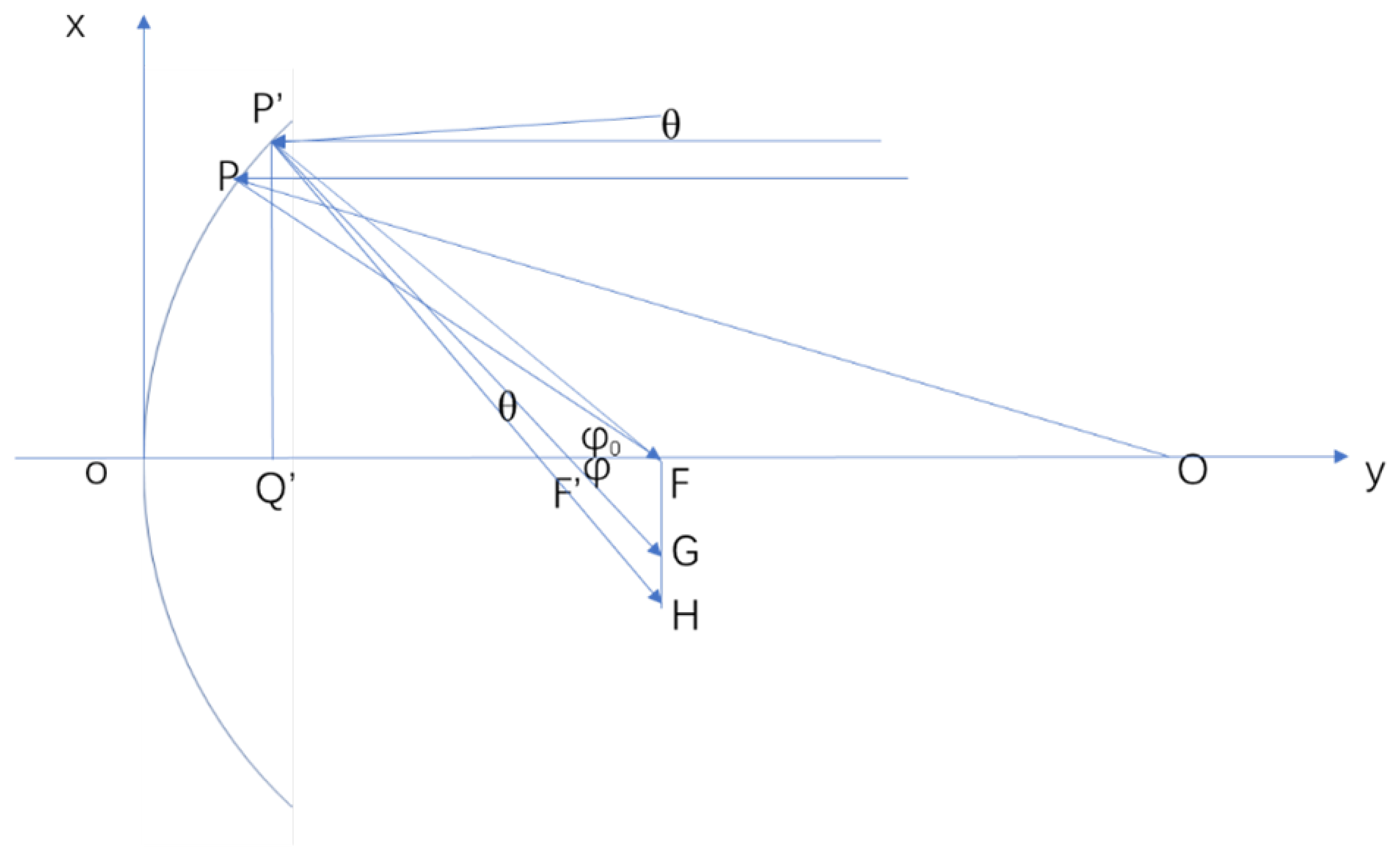
Figure 2.
Trough System intercept factor calculated using the ray-tracing method, cone optics method and SolTrace software at different receiver half-widths.
Figure 2.
Trough System intercept factor calculated using the ray-tracing method, cone optics method and SolTrace software at different receiver half-widths.
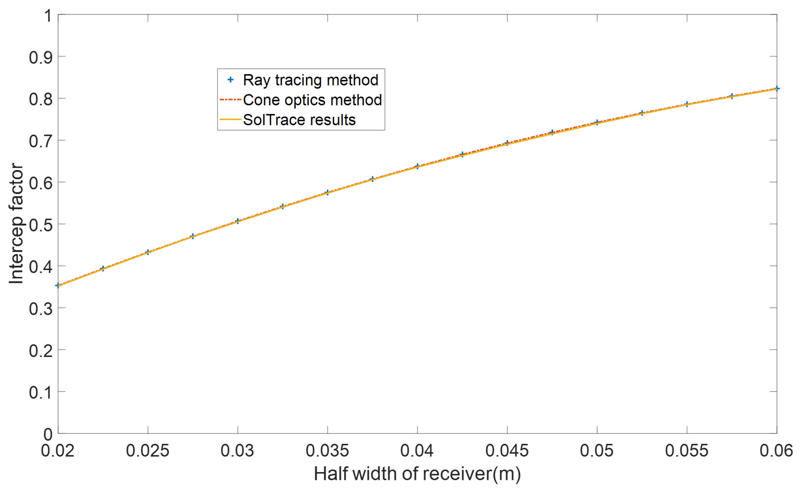
Figure 3.
The intercept factor of the cylindrical mirror spliced concentrator with cavity receiver changes with the incident angle under different slope errors.
Figure 3.
The intercept factor of the cylindrical mirror spliced concentrator with cavity receiver changes with the incident angle under different slope errors.
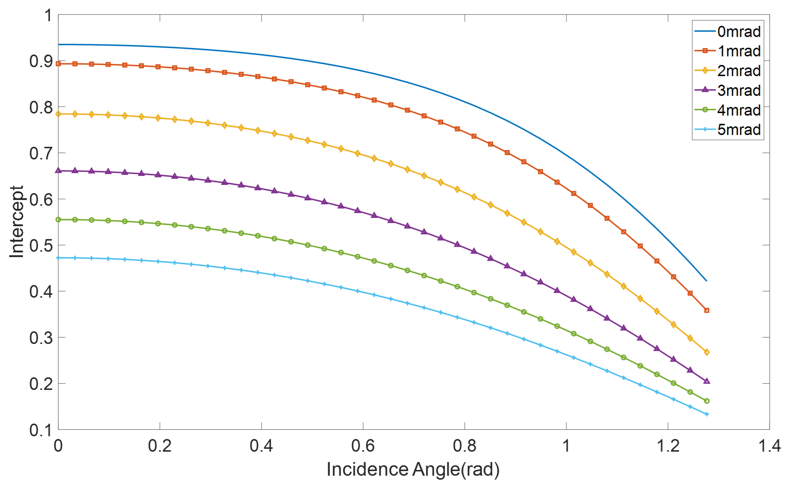
Figure 4.
The net efficiency of a spliced trough system with a cavity receiver at different f/w.
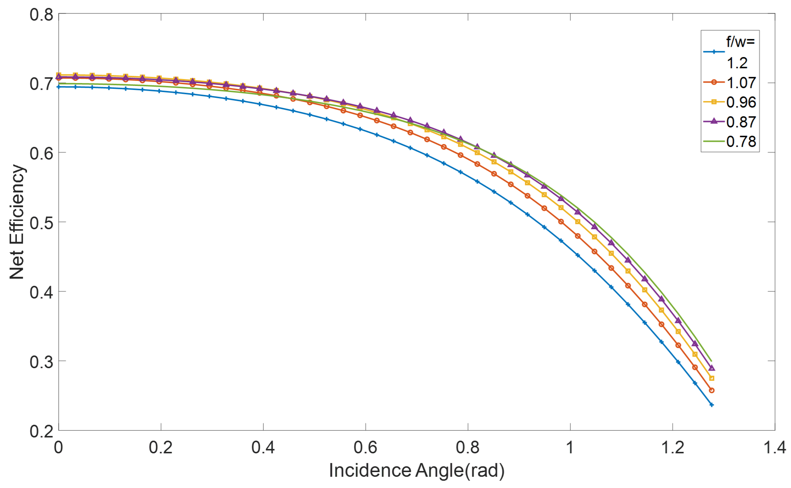
Figure 5.
The net efficiency of a cylindrical mirror spliced trough concentrator with a cavity receiver at different r/f.
Figure 5.
The net efficiency of a cylindrical mirror spliced trough concentrator with a cavity receiver at different r/f.
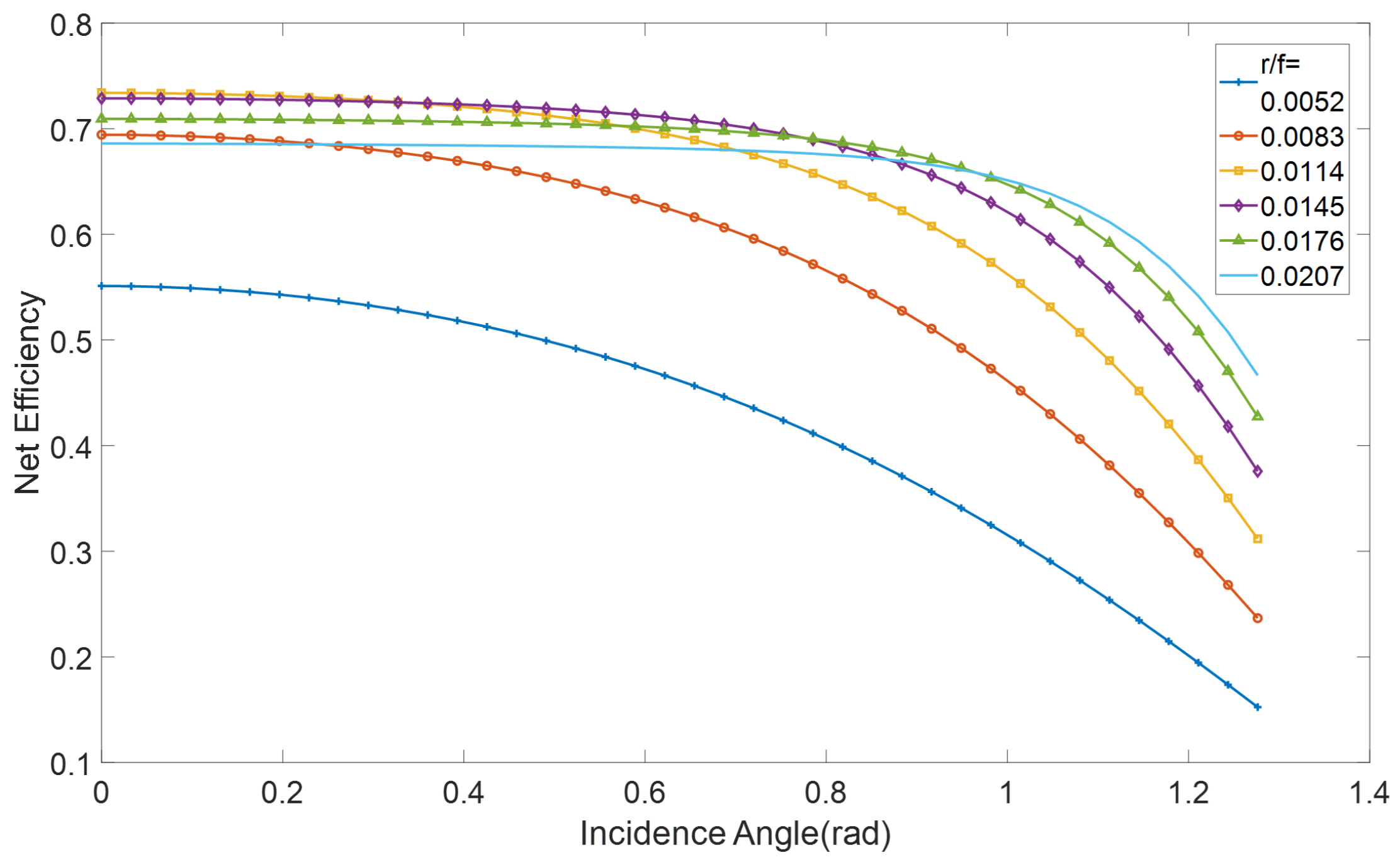
Figure 6.
Annual average net efficiency changes of cylindrical mirror spliced trough with cavity receivers under different f/w and r/w parameters in (a) East-West tracking modes and (b) North-South tracking modes.
Figure 6.
Annual average net efficiency changes of cylindrical mirror spliced trough with cavity receivers under different f/w and r/w parameters in (a) East-West tracking modes and (b) North-South tracking modes.
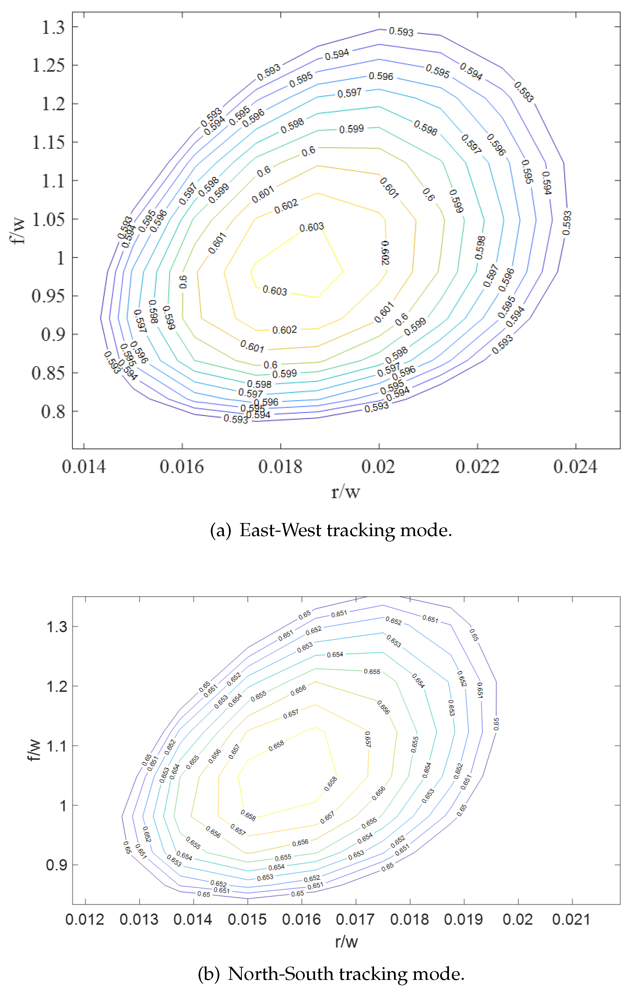
Figure 7.
The Annual average net efficiency of four types of trough solar concentrators under north-south axis tracking mode in the year 2020.
Figure 7.
The Annual average net efficiency of four types of trough solar concentrators under north-south axis tracking mode in the year 2020.
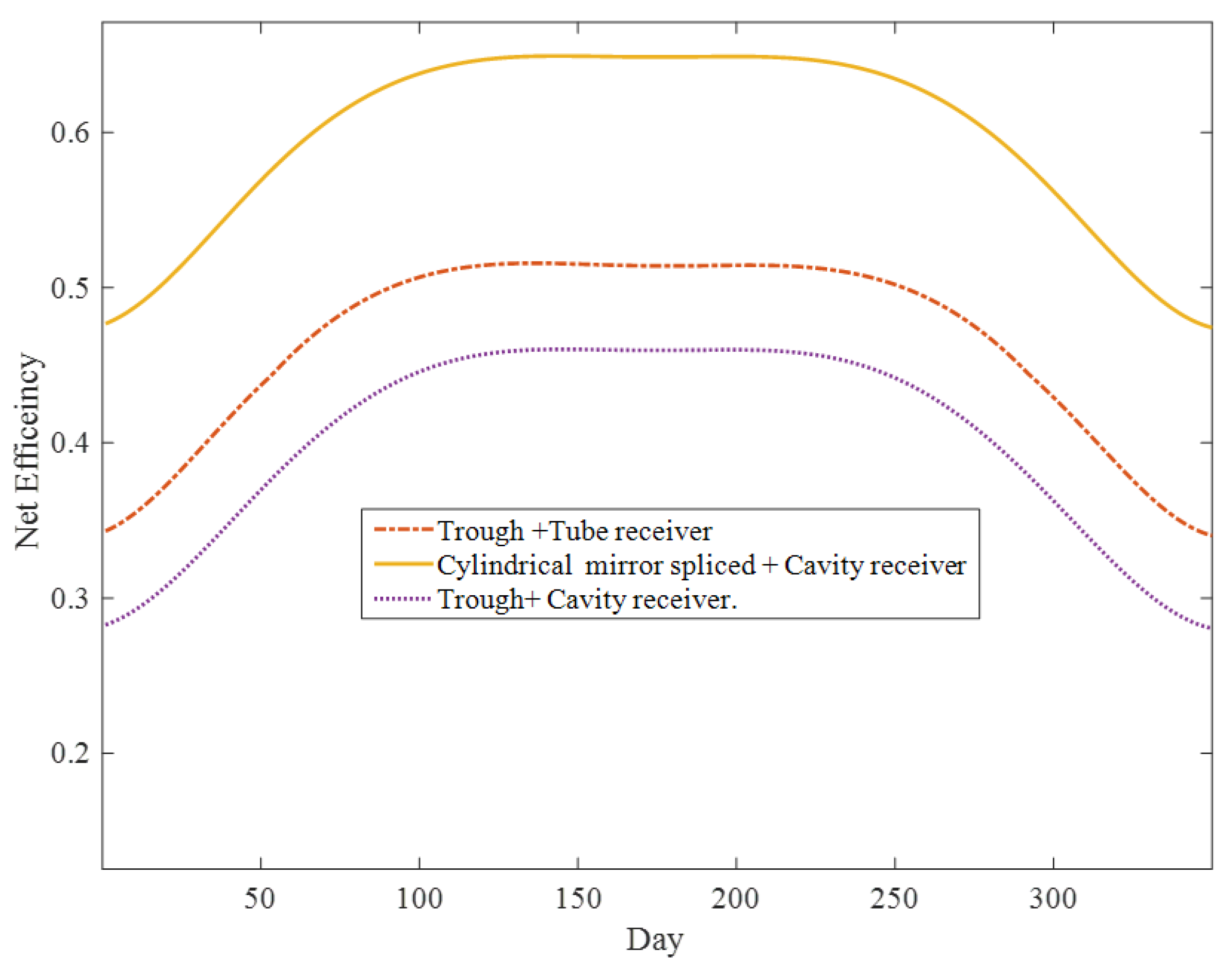
Table 1.
Parameterof the typical parabolic trough solar collector.
| Parameter | Data |
|---|---|
| Focus length | 2 m(rim angle=90°),4.8m(rim angle=45°) |
| Half trough width w | 4 m |
| Length of trough L | 100 m |
| The half the width of the receiver | 0.04 m |
| Radius of envelope of receiver R | 0.055 m |
| Operation temperature of receiver T | 400°C |
| Transverse optical error | 6mrad |
| Longitudinal optical error | 6mrad |
| Tracking error | 0mrad |
Disclaimer/Publisher’s Note: The statements, opinions and data contained in all publications are solely those of the individual author(s) and contributor(s) and not of MDPI and/or the editor(s). MDPI and/or the editor(s) disclaim responsibility for any injury to people or property resulting from any ideas, methods, instructions or products referred to in the content. |
© 2024 by the authors. Licensee MDPI, Basel, Switzerland. This article is an open access article distributed under the terms and conditions of the Creative Commons Attribution (CC BY) license (http://creativecommons.org/licenses/by/4.0/).
Copyright: This open access article is published under a Creative Commons CC BY 4.0 license, which permit the free download, distribution, and reuse, provided that the author and preprint are cited in any reuse.


