
Submitted:
28 October 2024
Posted:
30 October 2024
You are already at the latest version
Abstract
Curved continuous steel box girders are extensively utilized in bridge construction due to its efficiency and environmental benefits. However, in regions with significant temperature fluctuations, temperature effects can result in cumulative deformation and stress concentration, which may severely impact structural safety and durability. This study examines the structural response of curved continuous steel box girders under diverse temperature conditions and also develops a comprehensive parameterized thermodynamic numerical model. The model assesses the influence of cross-sectional shape parameters including; the number of cross-sectional box chambers, diaphragm thickness, and height-to-width ratio, as well as longitudinal structural parameters such as planar configurations, width-to-span ratio, and support arrangements, along with the arrangement of stiffening ribs on the temperature-induced effects in the girders. Results indicate that optimizing the width and eccentricity of support stiffeners to 30% and 25% in the support plate size, respectively, can significantly alleviate local temperature-induced stresses. Additionally, variations in longitudinal and transverse stiffeners manifest minimal impact on thermal performance. These findings provide a theoretical foundation for improved design and construction practices, offering practical design recommendations to mitigate temperature effects and enhance the longevity and safety of such structures.
Keywords:
Bridge engineering
; Temperature effect
; Curved bridge
; Steel box bridge girder
; Temperature resistance
1. Introduction
In urban elevated expressway networks, steel box girders are extensively employed, particularly when addressing challenges such as limited pier positions, low bridge foundations, small curvature radii, and large spans, due to its superior bending and torsional resistance, rapid construction, and minimal traffic disruption [1,2,3]. In certain extreme scenarios, non-uniform temperature fields can significantly compromise the safety of steel box girder bridges. Continuous curved steel box girder bridges, due to their curvature, are particularly vulnerable to temperature effects [4,5,6,7]. Temperature loadings can induce continuous curved girders to arch outward or contract inward, leading to axial and radial displacements [8,9,10]. To mitigate the redundant forces generated at constraints due to temperature effects, curved steel box girders may experience creep at the supports [11,12]. Unreasonable radial constraint arrangements or impractical structural designs in steel box girder supports can result in excessive lateral stiffness. Consequently, temperature effects inevitably produce larger lateral forces and torques, elevating the internal stress levels of the structure and potentially reducing the service life of curved bridges.
Temperature effects on steel structure bridges have garnered significant attention from scholars worldwide, yielding substantial findings. The primary research methods employed are experimental testing and numerical simulation. Wang et al. investigated the entire construction process of a steel box girder bridge using measured temperature data from the steel box girder section [13]. Miao et al. compared the measured temperature stress data of the Runyang Yangtze River Bridge’s steel box girder with the theoretical temperature stress calculated according to Chinese standards. They found that the measured values exceeded the theoretical values from the standards, and stress concentration due to temperature loads primarily occurred near the welds of orthotropic steel box girders [14]. Zhou et al. demonstrated that transverse temperature differences are the primary factor causing lateral tilting of large-span steel box girder bridge decks. The temperature stress on steel girders is significantly greater than that caused by vehicle loads, and the temperature stress on some secondary components becomes the dominant load effect [15]. Zhang et al. analyzed factors affecting the temperature field of steel box girders using finite element software, focusing on parameters such as wind speed, solar radiation rate, and steel thermal absorption rate. The study revealed that the thermal absorption rate of steel is the most influential factor on the temperature effects of steel box girders without a paving layer [16]. Wang et al. developed a temperature prediction model for large-span flat steel box girders using field environmental parameters and machine learning methods [17]. Tao et al. measured and simulated the long-term temperature field of large-span bridge steel box girders, successfully achieving long-term temperature field simulation [18]. Huang et al. examined the impact of wind on temperature distribution and proposed a thermal analysis method for predicting the temperature characteristics of steel box girders based on the actual wind field distribution. They evaluated the temperature field characteristics of steel box girders using four indicators: effective temperature, vertical temperature difference, lateral temperature difference, and local temperature difference gradient [19,20]. In summary, existing research on temperature effects predominantly focuses on straight bridges or short curved bridges, providing valuable references for studying temperature effects on steel box girders. However, few scholars have investigated large-span, small-radius curved steel box girders as the subject of temperature effects research.
The impact of temperature on curved steel box girders is particularly pronounced. Xu investigated the temperature effects on continuous curved steel box girders and identified an overturning mode with the centerline of intermediate supports serving as the rotation axis [21]. It was also found that the fatigue strength of curved steel box girders significantly diminishes under prolonged temperature effects. Wan examined the impact of various support constraint forms on curved steel box girder bridges under lateral temperature gradient effects. The study found that appropriate eccentric supports can significantly enhance the stress distribution of curved steel box girders under temperature loads and reduce the risk of uplift at inner supports [22]. Yang et al. analyzed the temperature effects of asphalt concrete paving on S-shaped curved steel box girder cable-stayed bridges, discovering that paving temperatures induce significant displacements and stresses within the structure [23]. Wang investigated the deformation mechanism of continuous curved steel box girders under the temperature gradient mode specified by the British BS5400 standard. The study found that enhancing the constraint method of curved steel box girders and adopting a side-to-mid span ratio of 0.68:1 can significantly mitigate adverse stress levels caused by temperature effects [24]. Kim et al. developed a temperature prediction method considering solar radiation conditions, analyzed the thermal behavior of curved steel box girder bridges, and offered a reference for their design [25].
Based on both domestic and international research findings, existing studies on temperature effects predominantly focus on straight bridges or short curved bridges. Few scholars have investigated large-span, small-radius curved steel box girders as the subject of temperature effects research. The mechanism by which changes in structural parameters of continuous curved steel box girders influence local stress concentration and deformation inconsistency due to temperature effects remains unclear. Therefore, this paper references representative temperature load values from international standards and the latest research on bridge temperature fields to determine representative adverse natural environmental temperature conditions. Under such temperature conditions, the mechanical response mechanisms and deformation patterns of curved steel box girders are studied, and the influence patterns of various structural parameters on temperature effects are analyzed. This study provides a theoretical basis for more scientific design, maintenance, and reinforcement of large, long-span, small-radius, multi-span continuous curved steel box girder bridges.
2. Thermodynamic modeling of continuous curved steel box girders under variable temperatures
A thermal model of the curved steel box girder bridge is developed to simulate various temperature fields by adjusting the thermal boundary conditions. Subsequently, the results from the thermal analysis are integrated into the mechanical model, facilitating a comprehensive investigation of thermal dynamics parameters within the mechanical analysis.
2.1. Construction of the finite element model
The finite element software ANSYS 19.0 was utilized to develop a parametric numerical model of a five-span continuous curved steel box girder. This model features a 70-meter radius of curvature, a central angle of 135 degrees, and a uniform spacing of 3 meters between transverse diaphragms. It adopts a dual-chamber, single-box cross-sectional profile, as detailed in Figure 1. The cross-section of the box girder is defined by a height of 1.8 meters and a total deck width of 10.06 meters, with the upper flange measuring 2000 mm in width. The top and bottom plates are consistently 16 mm thick, with the bottom plate extending to a width of 6060 mm. The web and transverse diaphragm plates are 16 mm and 12 mm thick, respectively. Longitudinal stiffeners, oriented along the bridge’s longitudinal direction with closed ends, are 8 mm thick and 300 mm wide, spaced at intervals of 550 mm and 720 mm. Additionally, eight flat stiffeners, each 10 mm thick, are positioned 400 mm from the top and bottom plates. Transverse diaphragms are placed at regular 3-meter intervals along the bridge, with transverse stiffeners located mid-span between diaphragms, measuring 375 mm in height and 12 mm in width. To ensure optimal structural force distribution, the model employs a side-to-middle span ratio of 0.86:1 and a middle-to-end span ratio of 1:1, in accordance with Chinese highway steel bridge standards. The dimensions for both longitudinal and transverse stiffening ribs conform to standardized values as listed in Table 1.
In the ANSYS modeling process, the absence of a specialized higher-order beam element for thermal analysis necessitates the use of LINK33 elements to represent the thermal behavior of the longitudinal stiffening ribs. Thermal data derived from the mechanical analysis are applied to BEAM188 elements, which support thermal degrees of freedom, facilitating further computational procedures. For thermal and static analyses, the top and bottom flanges, web, and transverse diaphragms are modeled using SHELL131 and SHELL181 elements, respectively. LINK33 and BEAM188 elements are used to model the stiffening ribs, while SOLID279 and SOLID186 elements are employed to depict the bearings.
Considering the variable temperature distribution within the steel box girder, a transient thermal analysis is carried out using the ANSYS Workbench module. To accurately capture the diverse cross-sectional characteristics of the stiffening ribs in the steel box girder, specific cross-sectional properties are assigned. A global mesh size of 180 mm is selected to ensure modeling precision, with the resulting finite element model shown in Figure 2.
In configuring the heat transfer boundary conditions for the temperature field in the finite element model of the continuous curved steel box girder, the three primary mechanisms of heat transfer—conduction, radiation, and convection—are simulated using specific coefficients for thermal conductivity, radiative heat transfer, and convective heat transfer. These coefficients are provided in Table 2. The support system for the continuous curved steel box girder consists of a dual-bearing setup, designed to function under simple support conditions to ensure static determinacy. The eccentric distance, defined as the offset between the centroidal axes of the inner and outer bearings relative to the girder’s central axis, is set at 2.4 m. This support arrangement is illustrated in Figure 3.
2.2. Finite element model validation
To verify the accuracy of the finite element model, a comparison was conducted between the temperature field results from the finite element analysis of the continuously curved steel box girder and field measurement data from a similar real-world structure. The experimental setup included six measurement points arranged in a non-equidistant vertical array on the outer web of the girder section across the entire bridge span. The arrangement of these measurement points is shown in Figure 4. Temperature data collected from the corresponding heights at the measurement points on the side span of the outer web in the model were compared with the actual measured values, as depicted in Figure 5 and Figure 6. It was found that the standard deviation between the simulated and measured temperatures within 0.4 m of the top plate did not exceed 0.2, indicating a high degree of agreement between the simulated data and the actual measurements. Notably, the data from the 3# measurement point closely matched the actual temperature field. However, it was observed that temperature deviations at the 3# measurement point were generally higher than at other points, possibly due to the omission of solar and environmental radiation effects on the outer surface of the web plate in the simulation model. The maximum standard deviation observed was 0.75. Overall, the simulation results closely align with the trends and values of the measured data, validating the accuracy of the ANSYS model in simulating the temperature field of the steel box girder in a real-world scenario. This validation of the model’s accuracy supports its use for subsequent thermo-mechanical analyses of the continuously curved steel box girder.
3. Geometric properties of the cross-section
The construction form of the curved steel box girder bridge dictates the bending stiffness EI and torsional stiffness GId, both of which are crucial factors influencing bending-torsional deformation and the distribution of internal forces due to curvature [26]. Three representative adverse temperature conditions from the simulated temperature field are selected for analysis, as shown in Table 3. This research examines the impact of cross-sectional shape parameters—such as the number of compartments in the cross-section, cross-sectional stiffness, and aspect ratio of the cross-section—on the bending stiffness EI and torsional stiffness GId, and how these factors influence the temperature effects on curved steel box girders.
3.1. The number of cross-sectional box chambers
Using the model of a continuous five-span curved steel box girder bridge as a basis, derivative models with various cross-sectional configurations were developed by altering the number of webs. The study examined the thermal effects caused by the three different temperature field conditions mentioned in Table 3. Figure 7, Figure 8 and Figure 9 graphically depict the relationship between the number of compartments in the cross-section and key structural response indicators, including maximum equivalent stress, maximum shear stress, and maximum displacement.
Figure 7 and Figure 8 illustrate that, under varying temperature conditions, the trends in maximum equivalent stress and maximum shear stress in the continuous curved steel box girder follow a similar pattern with changes in the number of cross-sectional chambers: they initially decrease and then increase. Additionally, when the continuous curved steel box girder is configured with a single box and three chambers, the stress levels are significantly reduced under thermal-mechanical coupling conditions, making it more efficient than configurations with two or four chambers. As the number of chambers increases, the maximum deformation of the girder generally tends to decrease.
A comparative analysis of the deformation trend line for a four-chamber configuration against the interpolated maximum deformation results for three and five chambers reveals a reduced sensitivity of overall displacement to temperature fluctuations when an axial web is absent. The displacement variation remains under 2 mm. Consequently, it is concluded that the presence of an axial web within the cross-section significantly enhances the overall stiffness of the continuous curved steel box girder. Increasing the number of chambers strengthens the overall stiffness and reduces the deformation effects under thermal load.
3.2. The cross-sectional stiffness
Continuous curved steel box girders necessitate adequate torsional stiffness, and diaphragms typically feature a solid web structure. The impact of diaphragm stiffness and cross-sectional stiffness on the thermal response of continuous curved girders is investigated by varying the cross-sectional stiffness. It is essential that the diaphragm stiffness, denoted as K1, and the solid web stiffness, denoted as K2 meet the following criteria:
In the formula, Ld denotes the diaphragm spacing, which is set at 3 meters. E represents the elastic modulus of the steel, while Idw is the principal sector moment of inertia of the girder-shaped cross-section. The shear modulus of the steel is indicated by G, td denotes the thickness of the diaphragm, and A refers to the cross-sectional area of the box girder.
In the formula, Fu represents the cross-sectional area of the top slab of the box girder, including the stiffening ribs. Fl denotes the cross-sectional area of the bottom slab of the box girder, also including the stiffening ribs. Fh is the cross-sectional area of a web.
Ifu is the moment of inertia of the top slab about the symmetrical axis of the box girder, Ifl is the moment of inertia of the bottom slab about the symmetrical axis of the box girder, H is the web length, Bu is the width of the top slab excluding the flange plate, and Bl is the width of the bottom slab.
Calculated from the model’s geometric parameters:
By formulas 5 and 6, it is calculated that:
Substitute e and f into equations 3 and 4, and calculate to obtain:
Substituting into equation 2, we calculate:
Therefore, the minimum stiffness of the diaphragm for the study model is: 3245.6MN·m
The minimum diaphragm thickness of the research model is calculated using Equation 7:
Based on a minimum diaphragm thickness of 8 mm, two approaches were considered: (1) varying the thickness of all diaphragms, and (2) altering only the thickness of the support diaphragms while maintaining the middle diaphragms at a constant thickness of 12 mm. Both experiments were conducted under a thermal condition where the top plate was uniformly heated by 9 ℃. This resulted in curves of local maximum stress, maximum deformation, and diaphragm thickness changes, as illustrated in Figure 10, and curves of maximum equivalent stress, deformation, and changes in the top and bottom plate thickness, as shown in Figure 11.
Figure 10 and Figure 11 reveal that local stress concentration typically occurs near the supports under thermo-mechanical coupling, leading to similar results for both thickness variation schemes. This suggests that modifying the thickness of the support diaphragms significantly influences the local maximum stress induced by temperature effects on continuous curved steel box girders. Increasing the thickness of the support diaphragms from 10 mm to 20 mm results in a reduction of local maximum stress by approximately 33%.
As the thickness of the support diaphragms increases, the disparity in thickness between the support diaphragms and other diaphragms also increases, which leads to a reduction in the maximum deformation of the continuous curved steel box girders under combined temperature and constant load conditions. However, this reduction is minimal; as the thickness difference increases from 10 mm to 20 mm, the deformation reduction is only 1.5%.
3.3. cross-sectional aspect ratio
It is feasible to study the influence of the cross-sectional λ on the temperature effect of curved box girders by changing the aspect ratio of the section. To fully demonstrate the impact of λ on the temperature effect of curved box girders, twelve groups of different structural parameters were selected, as shown in Table 4, to investigate the relationship between λ, stress, and deformation. To investigate the influence of the cross-sectional aspect ratio λ on the temperature effects in curved box girders, it is feasible to vary the aspect ratio of the section. To comprehensively demonstrate the impact of λ on the temperature-induced effects in curved box girders, twelve groups of different structural parameters were selected, as outlined in Table 4. These groups were used to explore the relationship between λ, stress, and deformation.
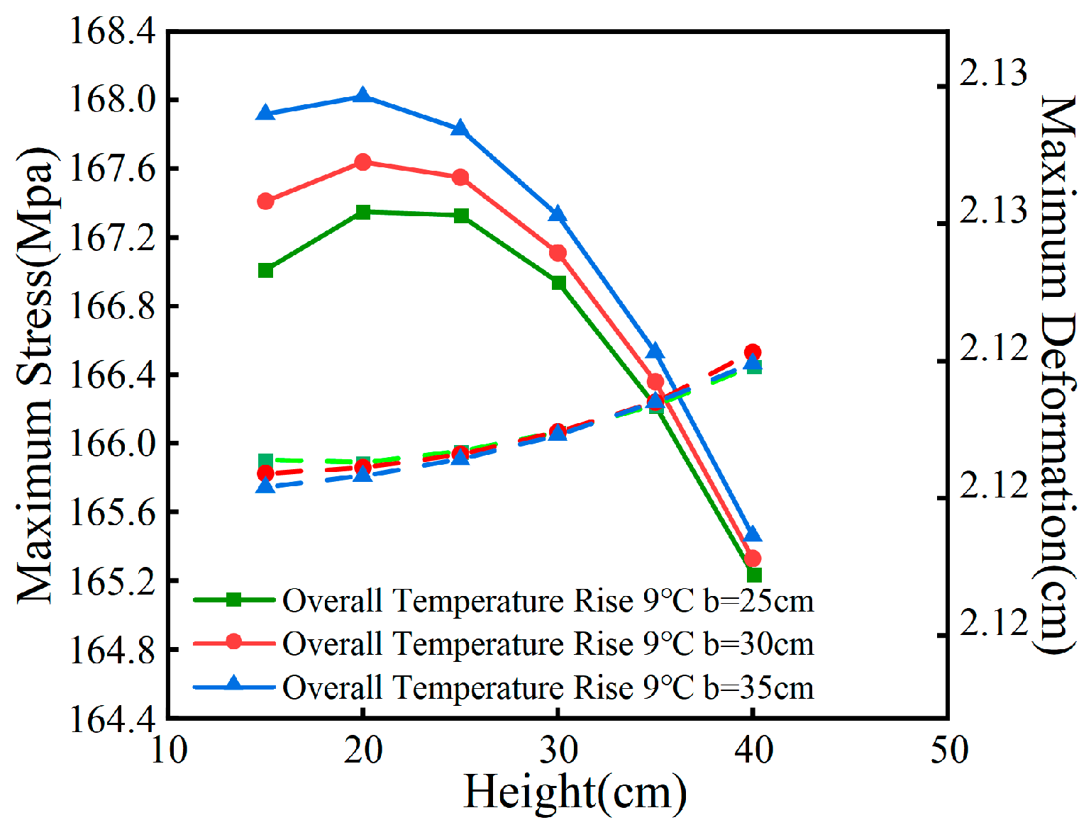
Figure 12.
Influence of aspect ratio on stress results.
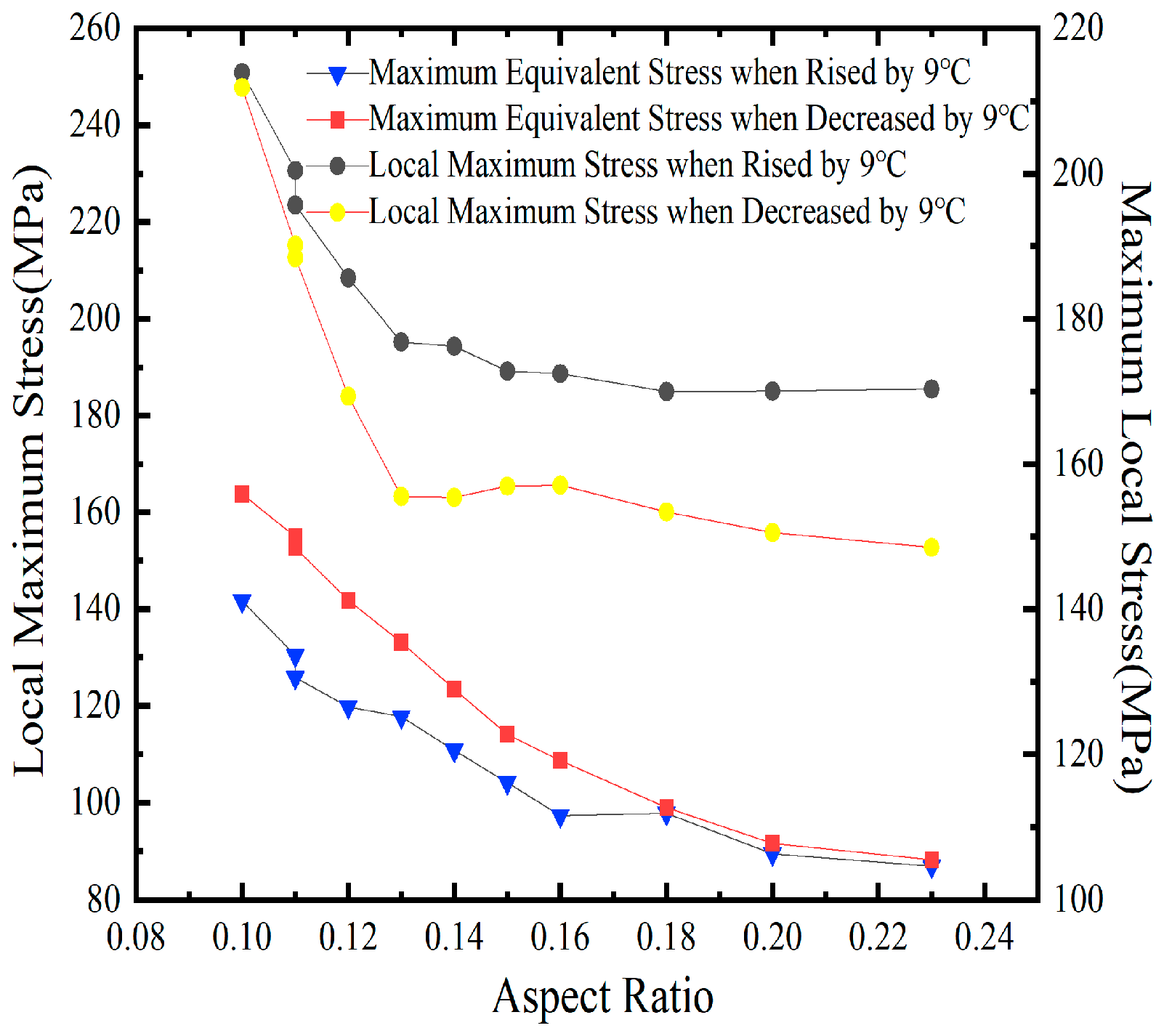
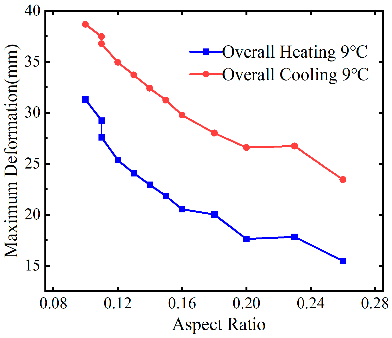
Figure 13.
Influence of aspect ratio on deformation results.
4. Influencing factors on temperature effect of longitudinal bridge
4.1. Longitudinal bridge alignment
The structural parameters and constraint methods of a bridge in the longitudinal direction can significantly influence the temperature effects on curved box girders. This research focuses on key parameters of the longitudinal bridge alignment, including the radius of curvature R, the central angle θ, and the total length L of the curved steel box girder bridge. Following trial calculations and analysis, radii of curvature of 69 m, 86 m, and 103 m were selected for study. Four models of curved steel box girders with varying numbers of spans were developed, as detailed in Table 5.
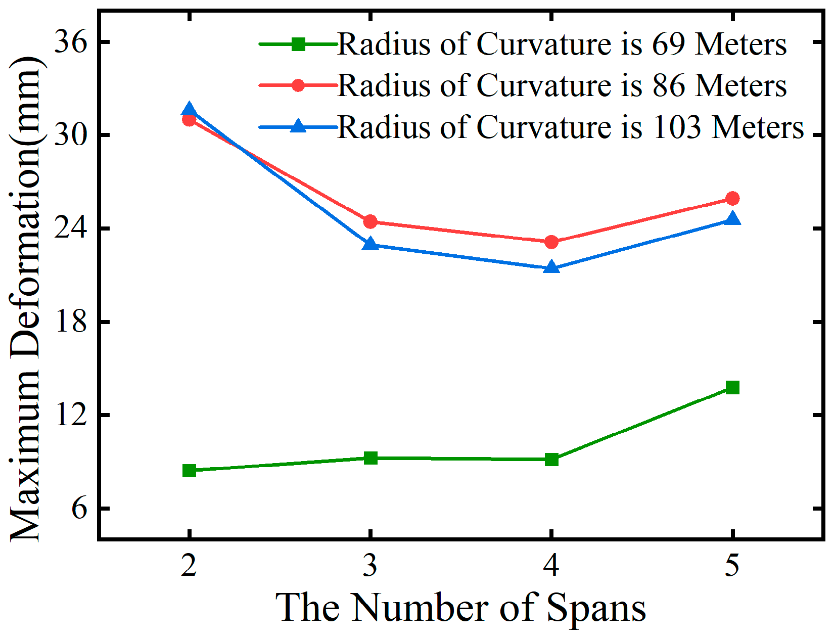
Temperature loads, dead weight, and a secondary constant load of 25 kN/m are applied to 12 curved steel box girder models. The initial temperature of the temperature field is set at 37 °C. Two temperature change scenarios are considered, both starting from this initial temperature: an overall temperature increase of 9 °C and an overall temperature decrease of 9 °C. Analyses and calculations are performed for each scenario. The results of the maximum equivalent stress and deformation for the curved steel box girders, with varying spans under these temperature conditions, are presented in Figure 15, Figure 16, Figure 17, Figure 18.
Figure 14.
Model of four-span curved steel box girder bridge with a radius of 86m.
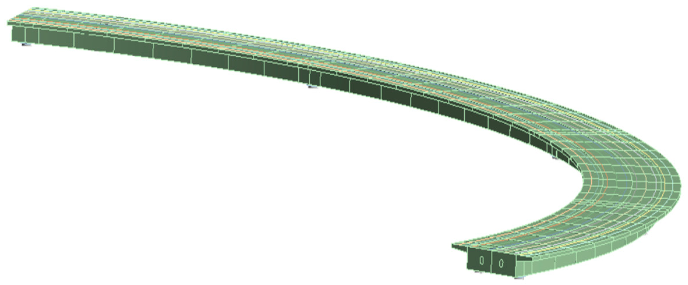
Figure 15.
Span number and maximum stress under overall temperature rise.
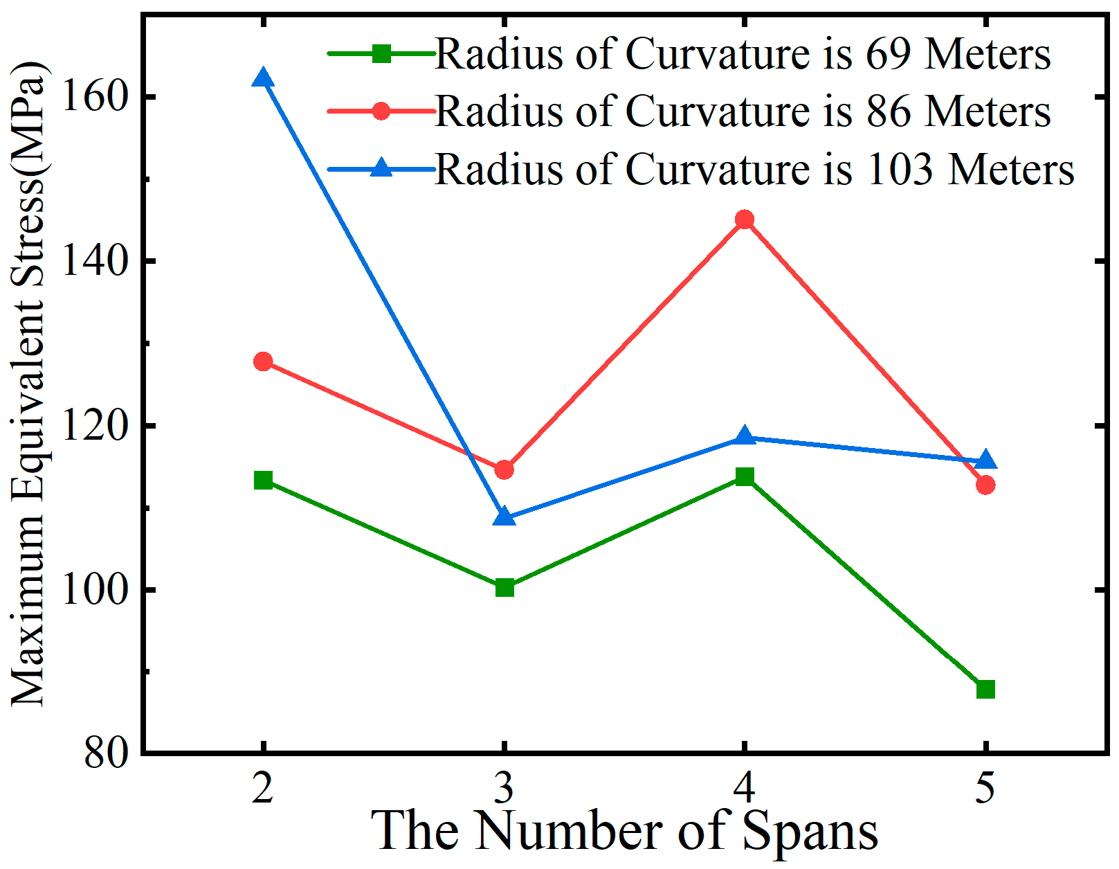
Figure 16.
Span number and maximum displacement under overall temperature rise.
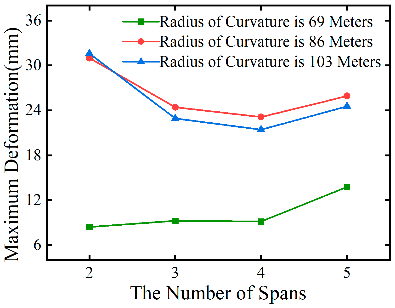
Figure 17.
Span number and maximum stress under overall cooling.
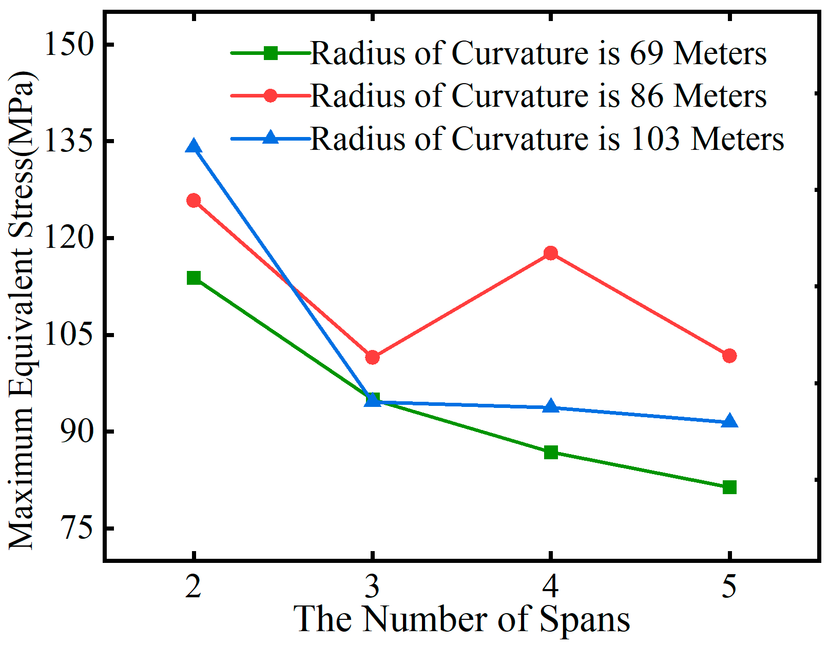
Figure 18.
Span number and maximum displacement under overall cooling.
From Figure 15, it is evident that under overall heating conditions, the maximum equivalent stress in curved steel box girders is slightly lower in odd spans compared to even spans. When comparing bridges in Group A and Group C with identical spans, it is observed that with a constant central angle θ, an increase in the radius of curvature R leads to an increase in the maximum equivalent stress caused by temperature effects and permanent loads, with a maximum increase of up to 28%.
From Figure 17, under overall cooling conditions, the maximum equivalent stress in curved steel box girders decreases as the number of spans increases. However, there is a slight increase in stress in even spans compared to adjacent odd spans.
Figure 16 and Figure 18 illustrate that, under both overall heating and cooling conditions, the radius of curvature is the primary factor influencing the temperature-induced deformation of curved steel box girders. Comparing bridges in Group B and Group C with the same span, it is observed that, for a given total bridge length L, a larger curvature ρ results in greater deformation due to temperature effects.
To further verify the observed patterns, a positive radial lateral temperature gradient and a negative radial lateral temperature gradient were applied to 12 models of curved steel box girder bridges. The initial atmospheric temperature was set at 37 °C, with a lateral temperature difference of 9 °C, resulting in a minimum lateral temperature of 37 °C and a maximum temperature of 46 °C. The calculation results for the maximum equivalent stress and deformation of the curved steel box girders, influenced by the lateral temperature gradient as the number of spans changes, are presented in Figure 19, Figure 20, Figure 21, Figure 22.
Figure 19, Figure 20, Figure 21, Figure 22 illustrate that, under lateral temperature gradients, the stress and displacement variation patterns of bridges with three distinct curvature radii, as the number of spans n changes, resemble those observed during an overall temperature increase. For a constant curvature radius R, as the central angle θ increases with the number of spans n, the maximum stress in even-numbered spans exceeds that in adjacent odd-numbered spans. When the central angles θ are equal, an increase in the curvature radius R results in a rise in the maximum equivalent stress in the curved steel box girder due to temperature effects and permanent loads. For equal span lengths L, the curvature ρ influences the temperature effects on the curved steel box girder. Greater curvature ρ with equal span lengths L leads to increased deformation.
4.2. Wide span ratio
As presented in Table 6, this section selects two sets of planar alignment parameters for curved steel box girder bridges to conduct modeling and simulation. By applying the combined effects of temperature and constant load to the two model sets, this study examines the impact of stress and deformation on the curved steel box girder as the span-to-width ratio δ varies with single-span length. This is analyzed under conditions of a 9 °C overall temperature increase and a 9 °C overall temperature decrease, while maintaining a constant bridge width b. The curved steel box girders utilize a single-box, double-cell section with a width of 10 meters. The span-to-width ratio δ for the two model sets ranges from 0.238 to 0.476. The top and bottom plates, as well as the webs, have a thickness of 16 mm, while the diaphragms have a thickness of 12 mm.
Figure 23.
Relationship between stress and deformation of group D with span number. (a) Overall heating condition. (b) Overall cooling condition.
Figure 23.
Relationship between stress and deformation of group D with span number. (a) Overall heating condition. (b) Overall cooling condition.
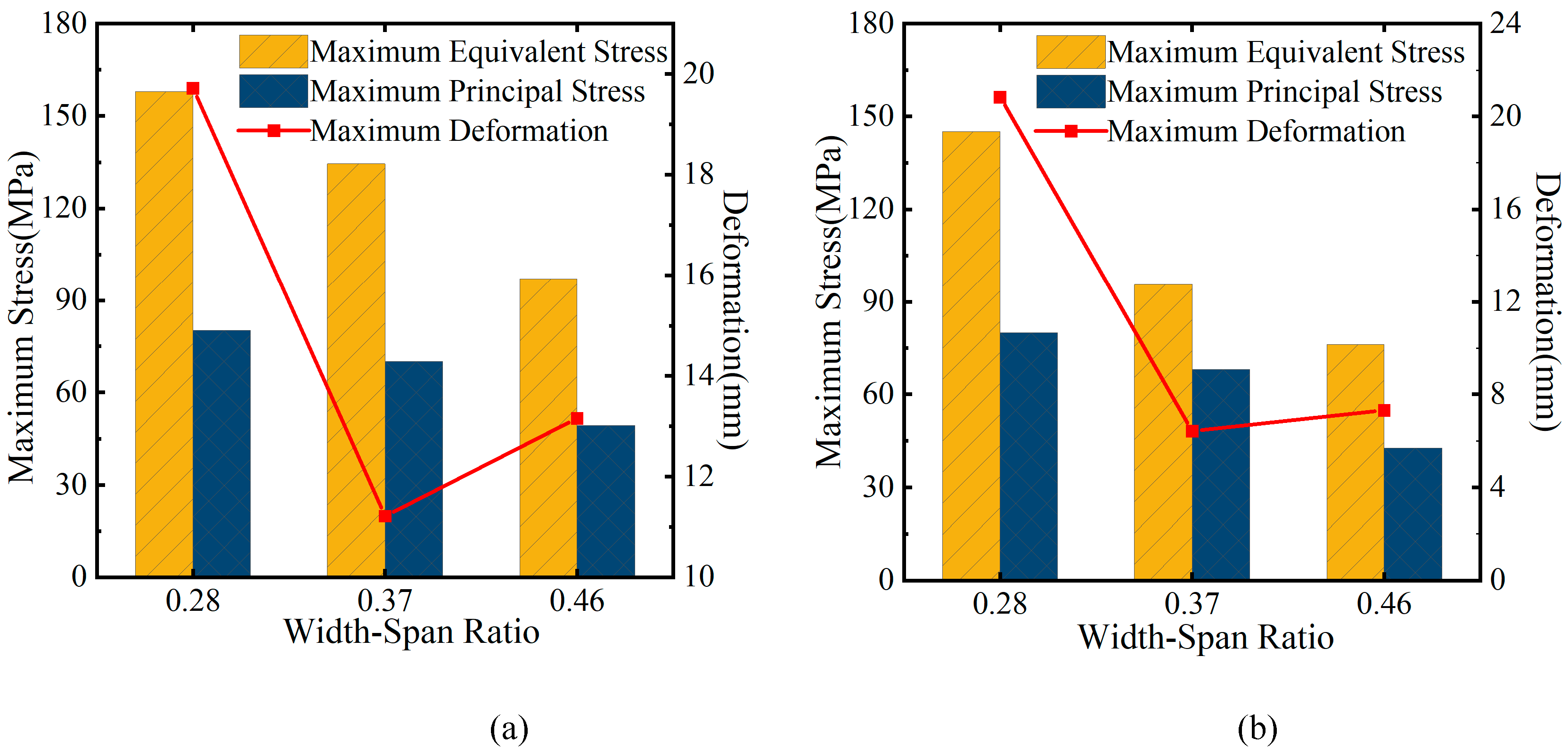
Figure 24.
Relationship between stress and deformation of group E with span number. (a) Overall heating condition. (b) Overall cooling condition.
Figure 24.
Relationship between stress and deformation of group E with span number. (a) Overall heating condition. (b) Overall cooling condition.
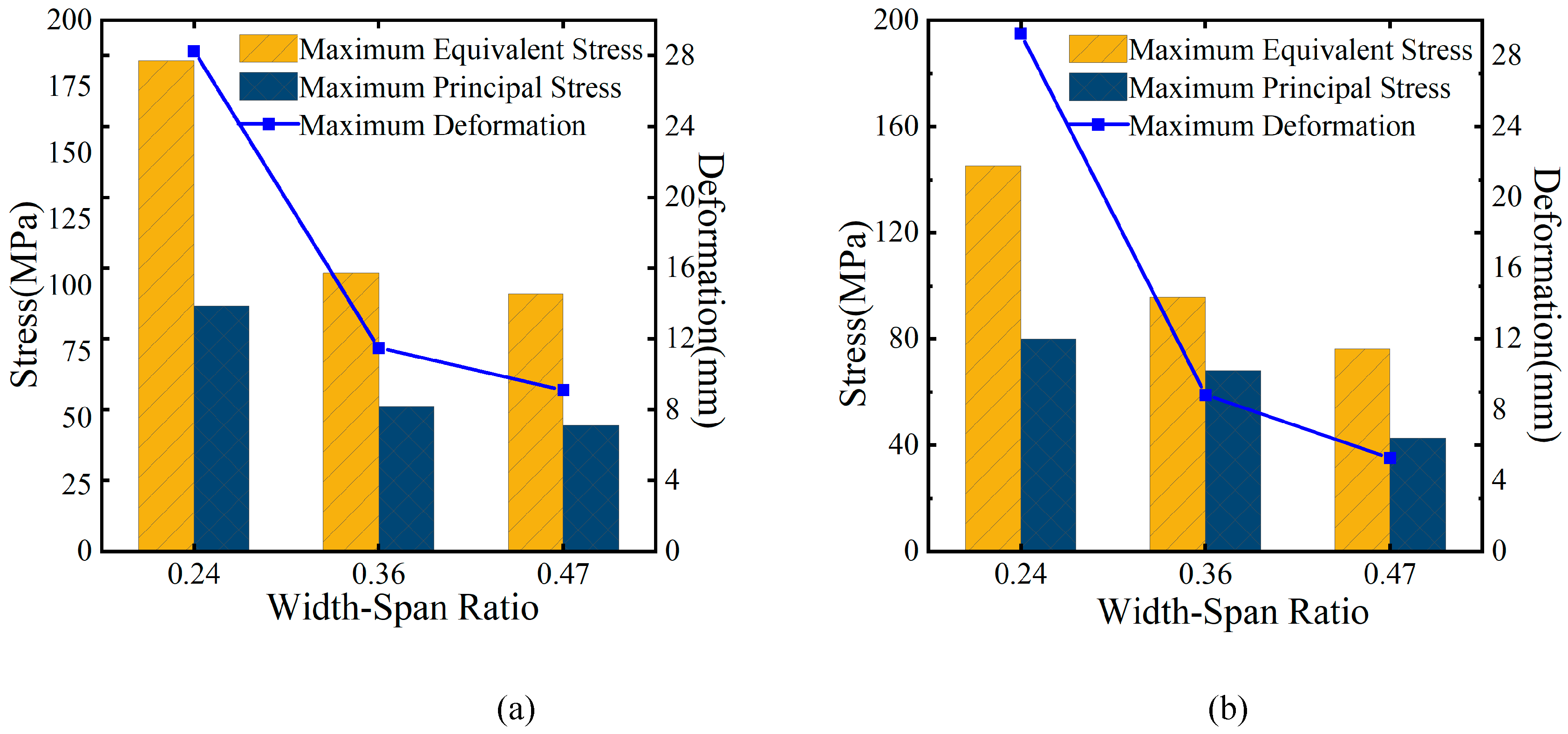
When the total bridge length L, radius of curvature R, central angle θ, and the bridge width b are fixed, increasing the single-span length of the curved steel box girder, which increases the width-to-span ratio δ, results in reduced stress on the curved steel box due to temperature effects. However, when the width-to-span ratio δ is less than 0.36, deformation due to temperature effects increases sharply as δ decreases. For a continuous curved steel box girder with a curvature radius of 69 m, increasing the width-to-span ratio δ from 0.28 to 0.46 results in a maximum stress reduction of 38.6% and a maximum deformation reduction of 64.9% due to temperature effects. For a continuous curved steel box girder with a curvature radius of 60 m, increasing the width-to-span ratio δ from 0.24 to 0.47 results in a maximum stress reduction of 47.5% and a maximum deformation reduction of 81.9% due to temperature effects. Therefore, when the bridge width is fixed, increasing the width-to-span ratio δ and reducing the single-span length of the curved steel box girder bridge can significantly reduce stress and deformation due to temperature effects. The larger the δ and the smaller the single-span length, the greater the reduction in stress and deformation caused by temperature effects. Table 7 and Table 8 present the statistical reductions in internal force and deformation values resulting from changes in δ for two model groups under conditions of overall heating and cooling.
Based on the statistical data presented in Table 7 and Table 8, it is evident that when the temperature rises, the rate at which stress decreases becomes more pronounced as the reduction in span diminishes. Conversely, when the temperature falls, the stress reduction rate diminishes as the reduction in span increases.
4.3. Support layout scheme
For continuous curved steel box girder bridges aligned in the north-south direction, differential solar exposure from the east and west leads to temperature variations between the inner and outer sides of the curved girder, creating lateral temperature gradients over the course of a day. This study examines how modifying the constraints of supports on both the inner and outer sides of the curved steel box girder affects its thermal response to these lateral temperature gradients.
With identical single-span lengths and side-to-mid-span ratios, the local maximum stress in a four-span continuous curved steel box girder is notably high under fluctuating temperature conditions. The study focuses on a four-span continuous curved steel box girder from the D group model, utilizing a dual-support simply supported system. By adjusting the positions of the fixed supports, the overall support configuration of the bridge is modified. Supports on the same side or section as the fixed supports employ unidirectional movable supports, while others utilize bidirectional movable supports. The detailed support configuration is provided in Table 9.
Figure 25.
Support number.
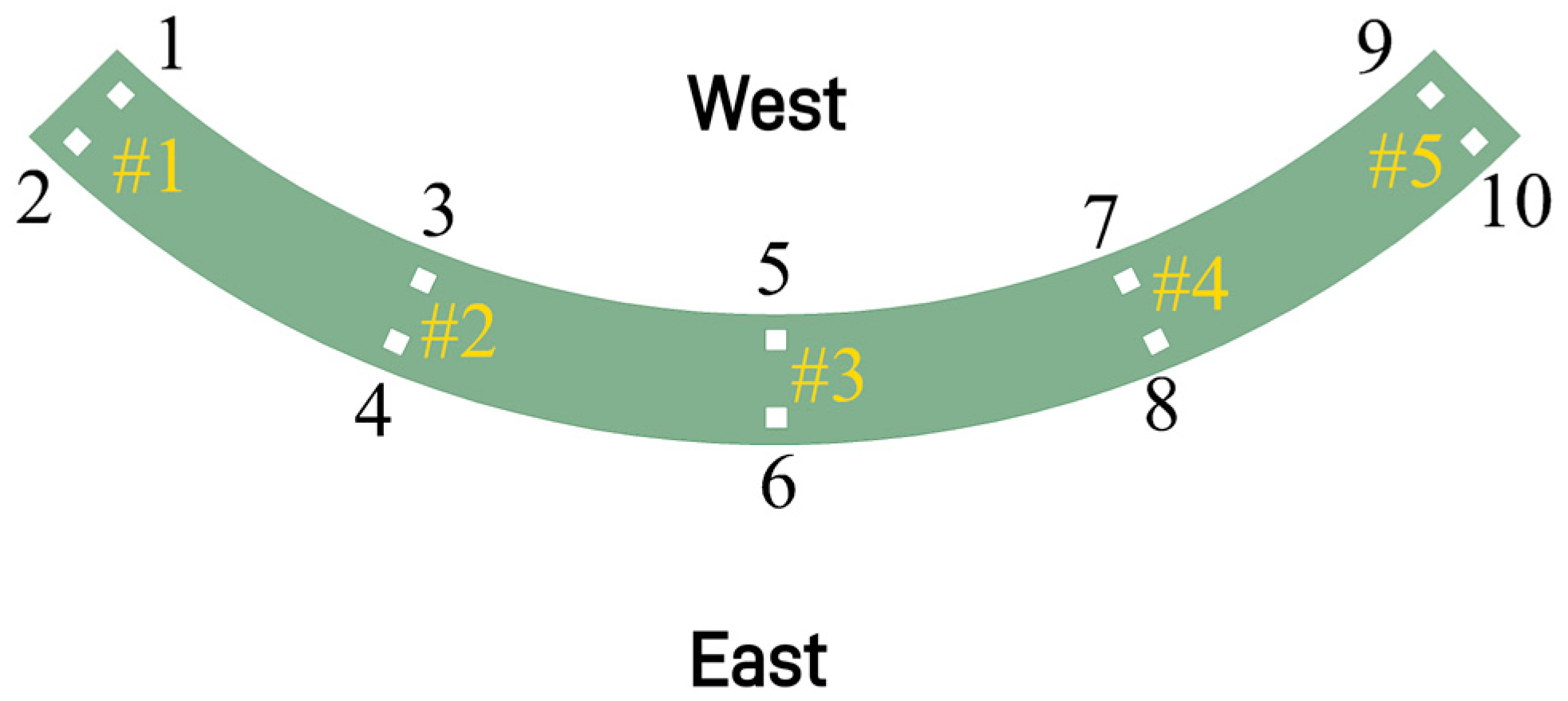
Figure 26.
Maximum equivalent stress of fulcrum section when exposed to sunlight in the east.
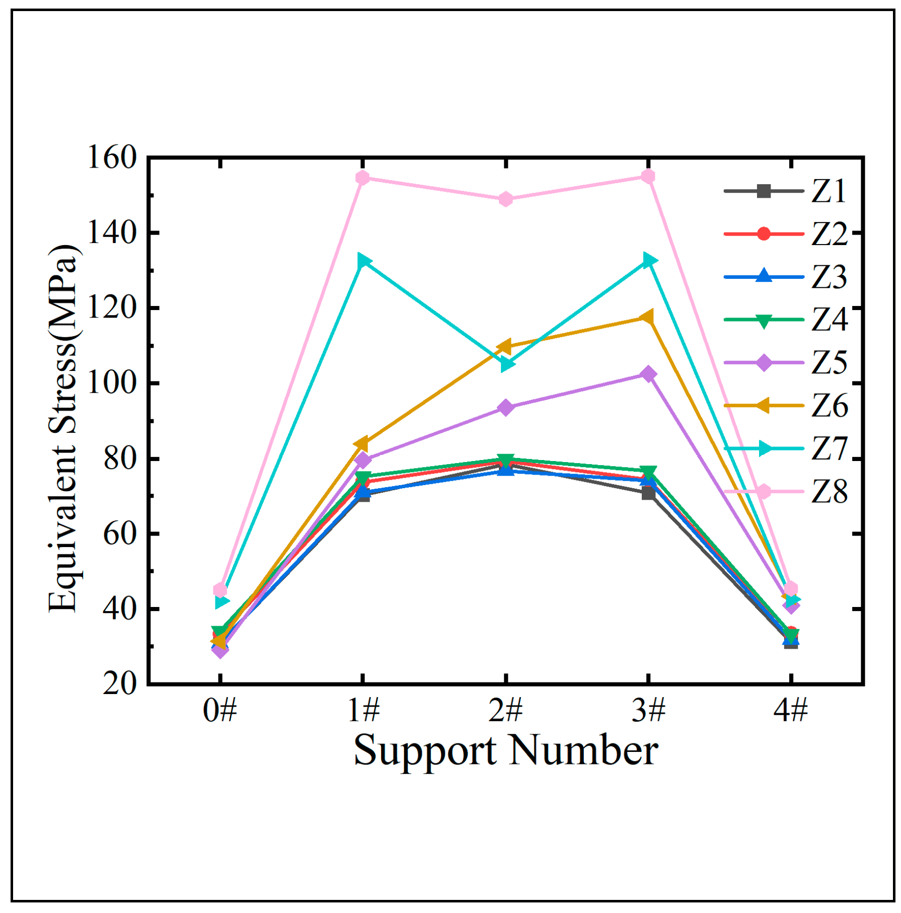
Figure 27.
Maximum equivalent stress of fulcrum section during sun exposure.
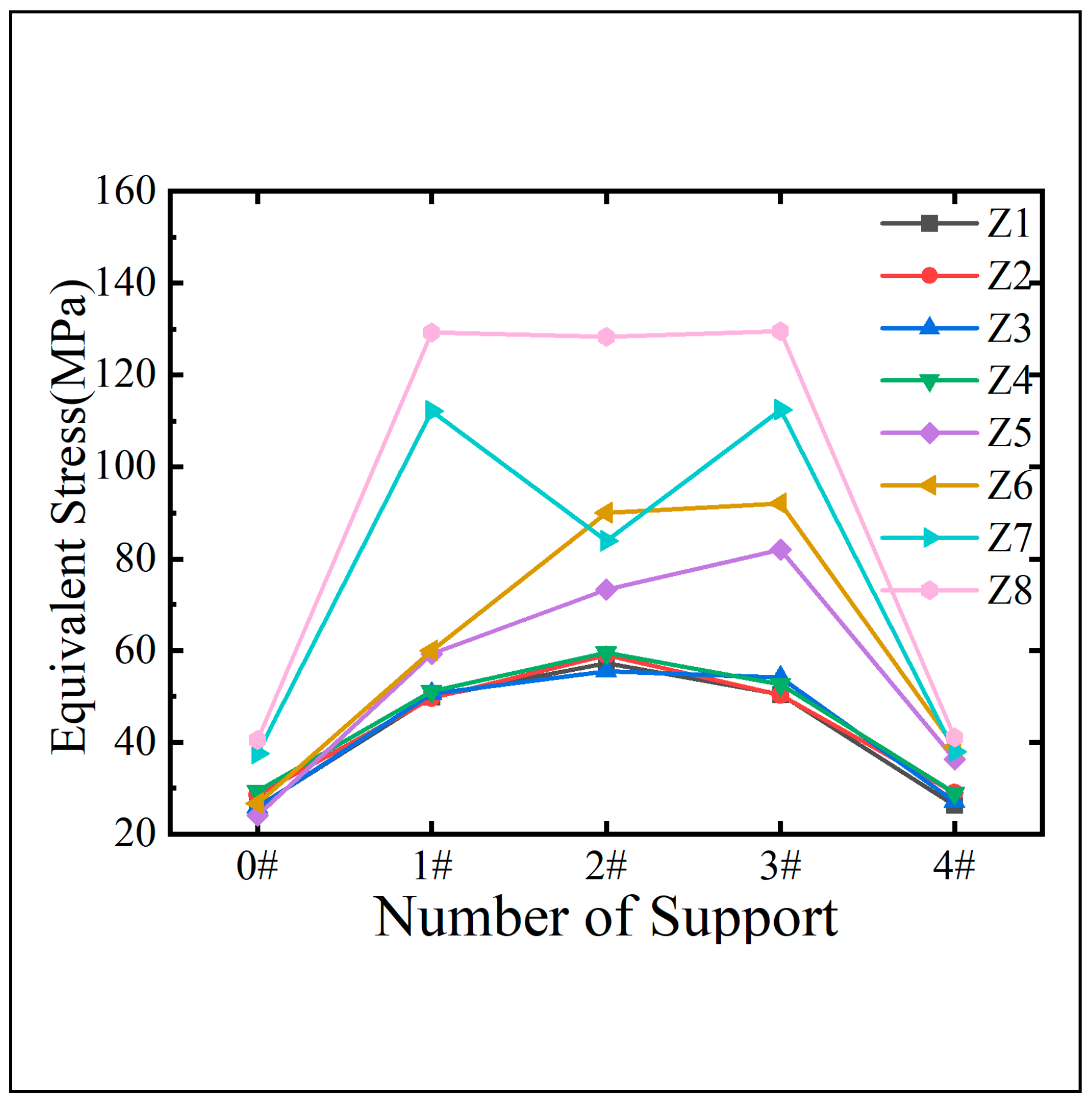
Figure 28.
Comparison of optimal stress arrangement schemes under partial sun exposure.
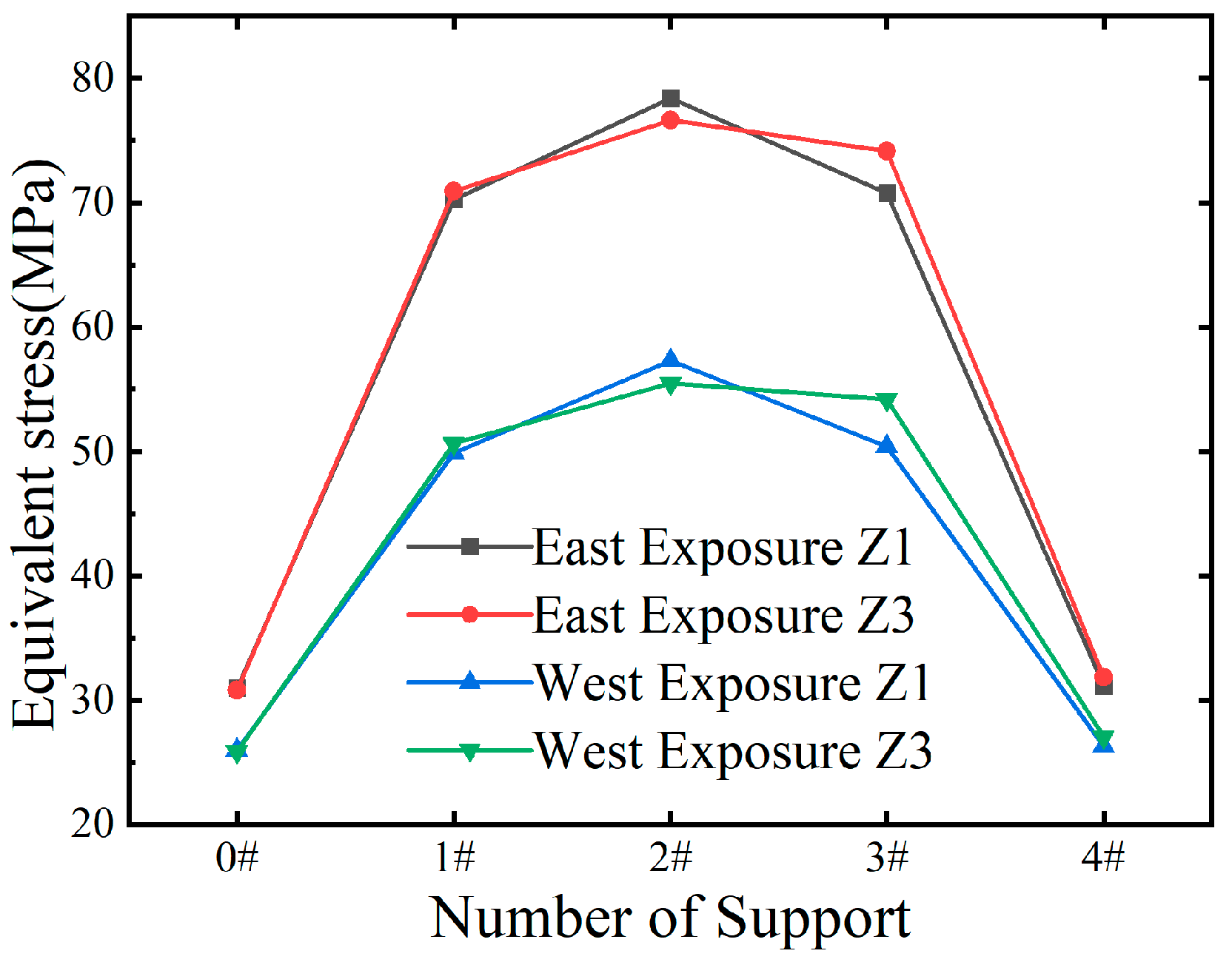
Considering the self-weight of the bridge and an additional dead load of 25 kN/m, numerical models representing eight distinct support arrangement schemes were analyzed under temperature fields resulting from east and west solar exposure. The maximum equivalent stress at each support section was determined, as illustrated in Figure 26 and Figure 27.
Figure 26 and Figure 27 illustrate that the local stresses at support points vary significantly across different support arrangements when subjected to the combined effects of solar exposure and constant loads in the same temperature variation environment. A comparison between schemes Z1 and Z8 reveals that the maximum stress at the same support point can differ by over 90 MPa. Schemes Z1 and Z3, which feature a single fixed support on the inner (west) side, exhibit lower equivalent stresses at the support points under both temperature conditions, with similar maximum equivalent stress values at the three intermediate support points. As shown in Figure 27, under east exposure conditions compared to west exposure conditions, the stress at the intermediate support points in schemes Z1 and Z3 increases by 36.8% and 38.1%, respectively. This suggests that temperature effects are more significant on the outer web than on the inner web. Under identical temperature conditions, scheme Z1 exhibits a lower average stress across all support point cross-sections compared to scheme Z3, although the cross-sectional stress at the middle support point is higher. Consequently, in practical applications, scheme Z1 should be locally reinforced at the middle support point cross-section.
From the perspective of overall average stress, scheme Z1, featuring a single inner curved support at the middle support point of a fixed multi-span bent steel box girder, emerges as the most rational support arrangement. This configuration effectively minimizes the overall average stress in the bent steel box girder when subjected to lateral temperature gradients.
Figure 28 presents the relationship between the maximum deformation and maximum equivalent stress of a four-span continuous bent steel box girder bridge in relation to variations in slope, as observed under the three temperature conditions detailed in Table 3. It is evident that as the longitudinal slope increases, there is a decrease in maximum deformation, whereas the maximum equivalent stress experiences an increase. The longitudinal slope plays a crucial role in influencing the temperature effects on the bent steel box girder when subjected to longitudinal bridge temperature differences. Particularly, when the longitudinal temperature gradient is contrary to the slope direction, it effectively reduces both the maximum equivalent stress and maximum deformation of the steel box girder.
5. Analysis of the effect of stiffening ribs on the temperature effect of bent steel box girders
5.1. Longitudinal stiffening rib
While keeping other geometric configurations constant, this study examines the effects of varying the number and spacing of closed-end stiffening ribs on the top surface of the steel box girder. The investigation evaluates how additional longitudinal bridging stiffening ribs on the top plate impact the stresses and displacements experienced by the steel box girder under the three temperature change conditions described in Section 3.1. The detailed results of this analysis are presented in Figure 29.
Figure 29 demonstrates that altering the number and arrangement of longitudinal, closed-end stiffening ribs on the top flange does not significantly reduce the structural sensitivity to thermal loads, although it does affect stiffness to some extent. Increasing the number of ribs resulted in only minor variations in structural deformation—limited to a 1.5 mm range—which is deemed negligible, while the maximum stress experienced a slight increase. Further analysis was conducted using a model with 12 stiffening ribs on the top plate, where the number of ribs on the bottom plate was increased from 6 to 8, evenly distributed. A comparative assessment with the original model revealed effects similar to those observed with additional longitudinal ribs on the top plate: the deformation of the curved steel box girder under the three specified temperature conditions showed minimal variation, with changes remaining under 1.5 mm after the addition of bottom plate ribs; however, the internal forces within the structure increased. This indicates that while the addition of stiffening ribs enhances structural stiffness, it does not significantly mitigate the internal forces under thermal loading but instead intensifies the structural stress.
To explore the effect of varying the number of longitudinal stiffening ribs on the web plate’s temperature response, the study utilized the 12-rib top plate model as a basis. The number of ribs on the outer and central webs was varied independently, and the resulting changes in stress and displacement in the steel box girder, due to the increased longitudinal web ribs under identical temperature conditions, are shown in Figure 30 and Figure 31. Figure 29 and Figure 30 reveal a significant increase in the local maximum stress within the bent steel box girder as the number of longitudinal bridging stiffening ribs on the outer web increases. However, this structural change results in a maximum displacement shift of less than 2 mm. While adding more longitudinal stiffening ribs to the central web had a similar impact on structural stress as observed with the side webs, the effect was comparatively milder and had virtually no influence on structural displacements.
While keeping the longitudinal dimensions of the U-ribs on the bottom plate constant, changes were made to the height h and width b of the rib on the top plate, thereby altering the section’s moments of inertia (Ix and Iy). This modification was designed to explore the impact of the flexural stiffness EI of the longitudinal bridging box stiffening rib on the temperature response of the curved steel box girder during an overall temperature increase of 9 ℃.
As shown in Figure 32, an increase in the bending stiffness EI of the closed-end stiffening rib section leads to a slight reduction in both the maximum stress and deformation of the bent steel box girder under a 9 ℃ overall heating scenario. The maximum stress decreases by no more than 2 MPa, and the maximum deformation reduction is limited to 10 mm. Figure 34 illustrates that reducing the width b of the bottom plate’s closed-end stiffening rib slightly decreases the local maximum stress, but by less than 1 MPa. As the flexural stiffness EI of the rib increases with the section height, the local maximum stresses in the bent steel box girder initially rise slightly before falling. When the section dimension h is less than or equal to b, the local maximum stress may increase; however, when h exceeds b, the reduction in local maximum stress becomes more pronounced, influenced by the stiffening rib’s cross-sectional moment of inertia Ix relative to the bottom plate. Despite these changes, variations in the bending stiffness EI of the bottom plate’s stiffening ribs have a negligible impact on the thermal deformation of the bent steel box girder, with the overall deformation remaining largely unchanged.
Figure 29.
Stress and displacement variations due to changes in the number of stiffening ribs at different temperature conditions.
Figure 29.
Stress and displacement variations due to changes in the number of stiffening ribs at different temperature conditions.
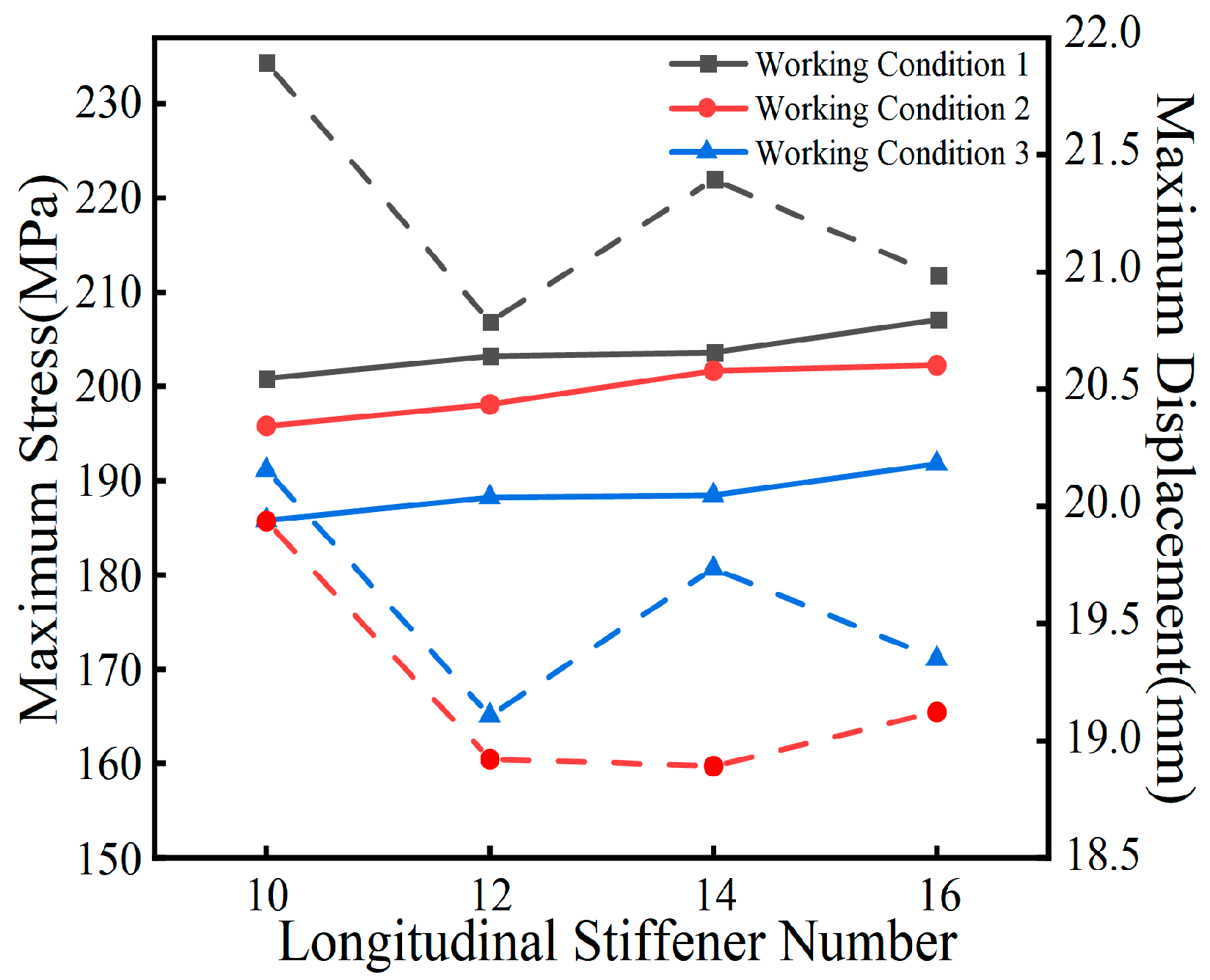
Figure 30.
Relationship between the number of longitudinal stiffening ribs in the outer web and the maximum stress and displacement.
Figure 30.
Relationship between the number of longitudinal stiffening ribs in the outer web and the maximum stress and displacement.
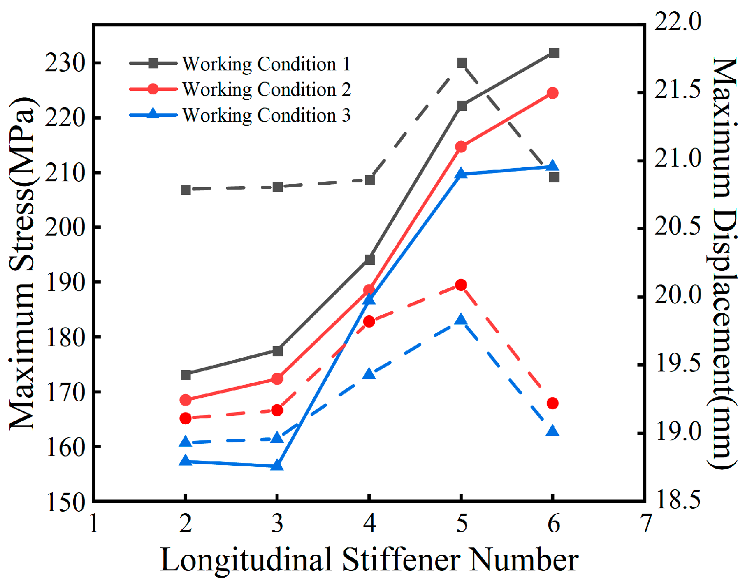
Figure 31.
Relationship between the number of longitudinal stiffening ribs and maximum stresses and displacements in the midweb plate.
Figure 31.
Relationship between the number of longitudinal stiffening ribs and maximum stresses and displacements in the midweb plate.
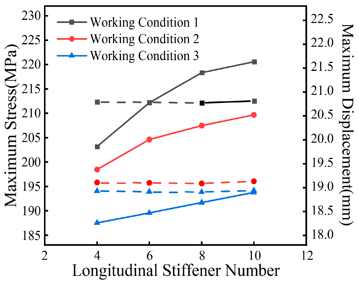
Figure 32.
Relationship between the height of the top plate closed-end stiffening rib section and maximum stress and displacement.
Figure 32.
Relationship between the height of the top plate closed-end stiffening rib section and maximum stress and displacement.
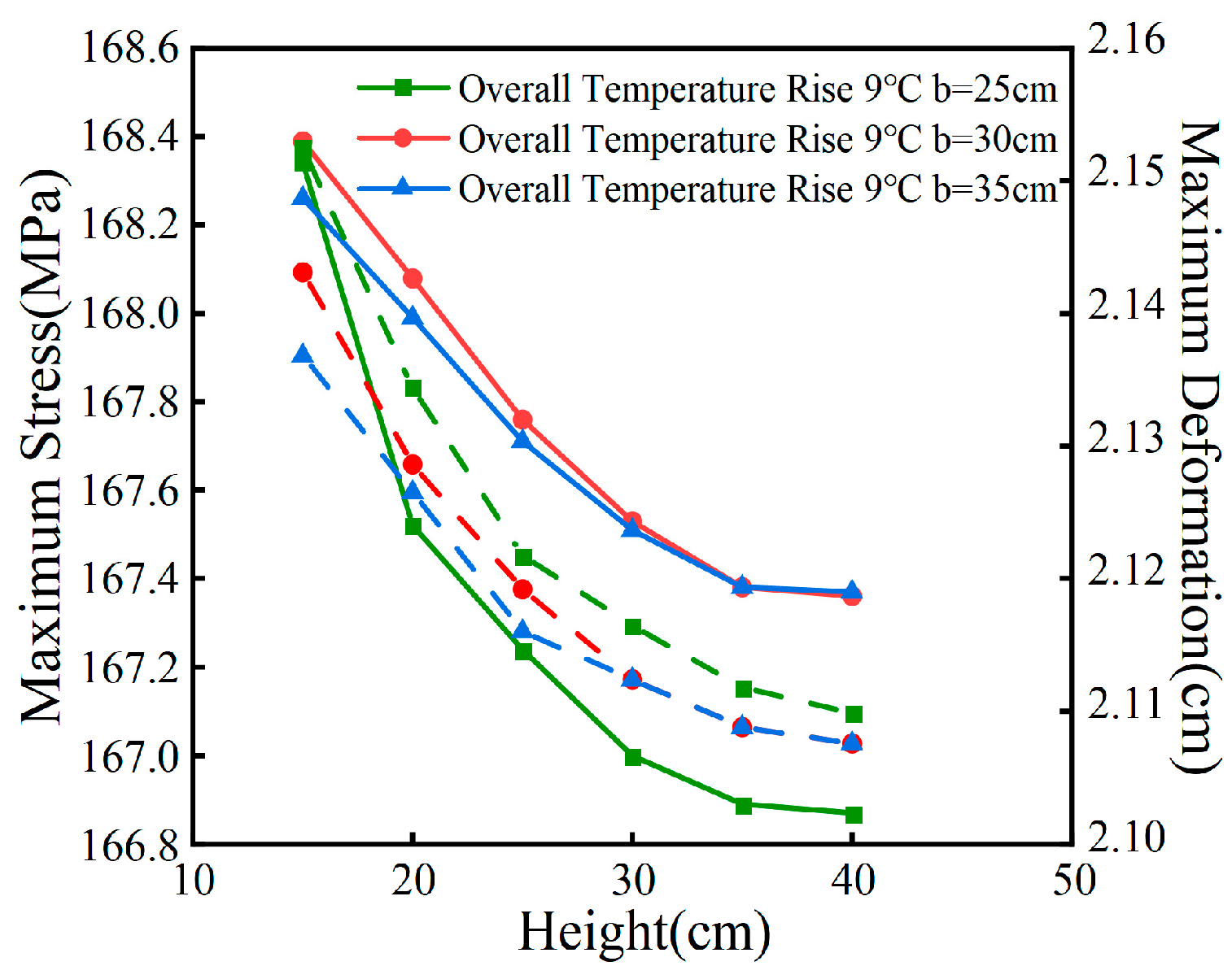
Figure 33.
Relationship between the height of the closed-end stiffening rib section and the maximum stress and displacement of the base plate.
Figure 33.
Relationship between the height of the closed-end stiffening rib section and the maximum stress and displacement of the base plate.
5.2. transverse-stiffening rib
Simulation analyses were conducted on models featuring 1 to 9 transverse stiffening ribs, spaced at 240 mm intervals on either side of the central support diaphragm. The outcomes of these simulations are illustrated in Figure 34. The results show that adding transverse stiffening ribs to the bottom plate near the center support diaphragm—close to the fixed bearing where the curved steel box girder experiences significant stress—is highly effective in reducing stress levels. This effect is particularly evident under the combined impact of temperature fluctuations and static load. Specifically, placing two transverse stiffening ribs on either side of the mid-span bearing diaphragm results in a maximum local stress reduction of up to 12% in a five-span curved bridge model under three different temperature conditions.
To evaluate the impact of transverse stiffening rib and support diaphragm spacing D and transverse stiffening rib spacing d on the temperature effects in a curved steel box girder, a series of numerical simulations were conducted using ANSYS software. The simulations began by varying the longitudinal bridging length L of the bearing from 600 mm to 900 mm in increments of 100 mm.
For each bearing dimension, six spacings were chosen, adhering to the condition D=d, with increments of 50 mm ranging from 250 to 500 mm. These 24 models were then subjected to a comparative analysis under a temperature scenario featuring a 9°C longitudinal gradient. The results are compiled and presented in Figure 35.
Figure 34.
Relationship between the number of transverse stiffening ribs and the maximum stresses and displacements in the base plate.
Figure 34.
Relationship between the number of transverse stiffening ribs and the maximum stresses and displacements in the base plate.
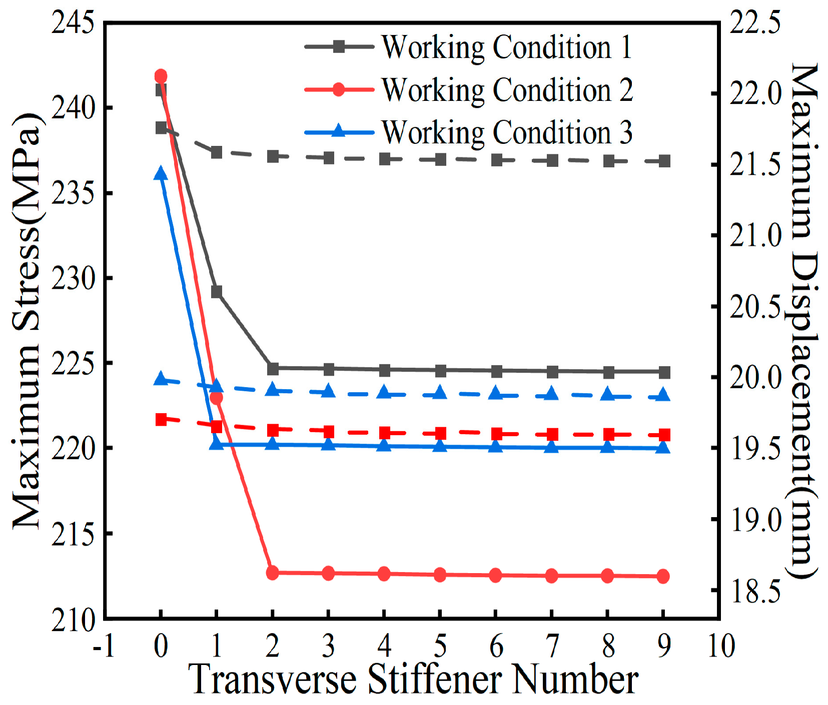
Figure 35.
Local maximum stress versus spacing D.
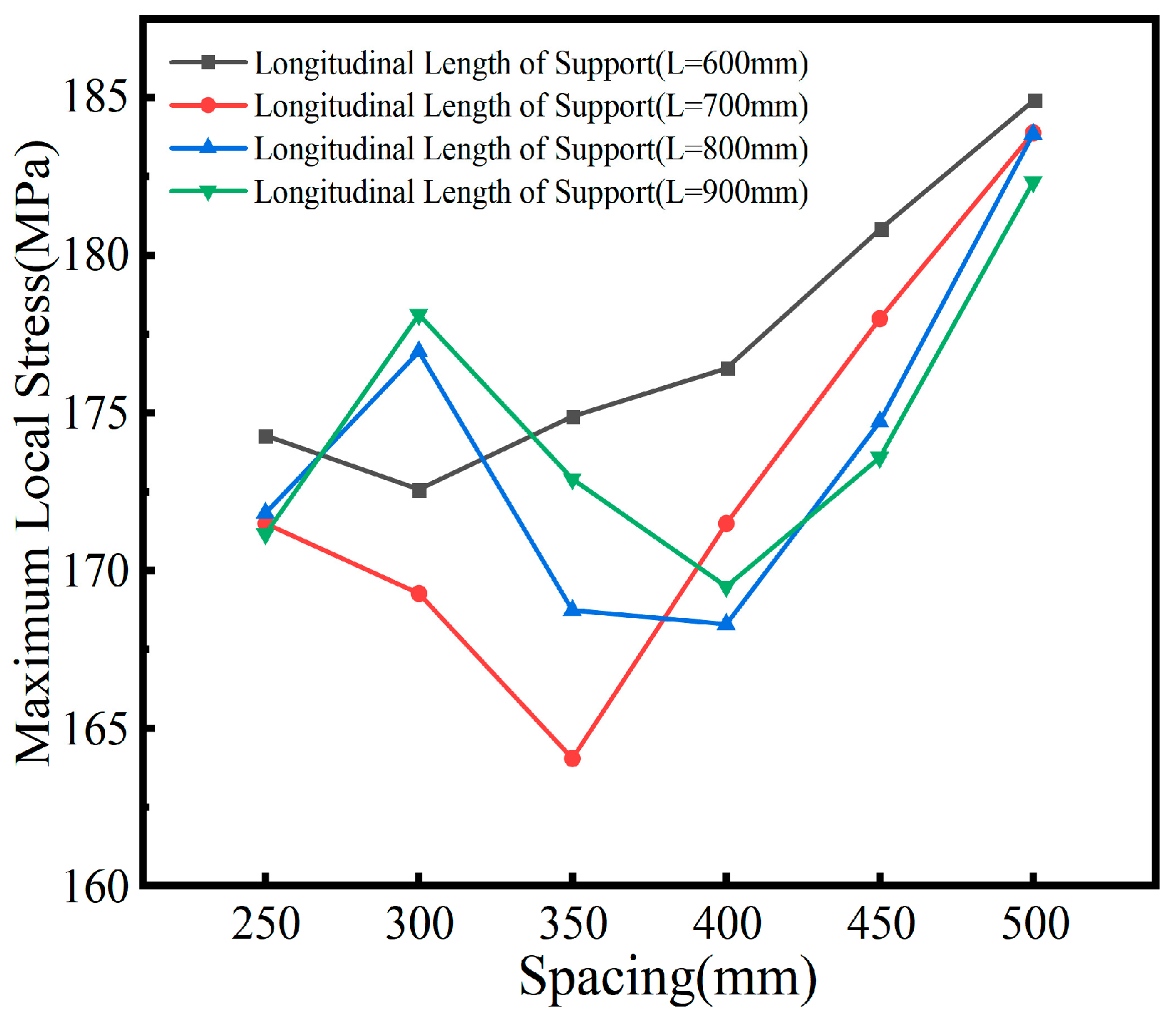
The analysis of Figure 35 reveals that when transverse stiffening ribs are arranged on the base plate with D = d ≤ 400 mm, the optimal spacing between these ribs and the transverse diaphragm is approximately half of the longitudinal bridging length L at the support. This configuration significantly reduces local stress concentration in curved steel box girders under thermal loading, thereby minimizing temperature-induced stress. However, when the longitudinal length of the bearing exceeds 900 mm, the effectiveness of the base plate’s transverse stiffening ribs in reducing localized stress concentration near the bearing diaphragm due to thermal loads decreases. As a result, the previously observed relationship no longer applies, and the optimal spacing tends to be around 400 mm.
5.3. Support-stiffening rib
The magnitude of the eccentricity B of the support stiffening rib, which depends on the transverse width L of the supporting plate, is typically positioned within the span of the supporting plate. With a stiffening rib thickness of t=10 mm and a width a=120 mm (where a/L=0.12), the relationship between the local maximum stresses at the transverse spacer of the support in the curved steel box girder and the ratio B/L under the combined influence of temperature and permanent load is illustrated in Figure 36. The figure indicates that as the B/L ratio increases, there is initially a decrease followed by an increase in the local maximum stress within the pivot transverse spacer, due to the combined effects of overall warming and permanent load. The optimal reduction in stress within the pivot transverse bulkhead due to thermal effects is observed when B/L is approximately 0.25. Beyond this ratio, the effectiveness of the support stiffening rib in reducing local stress on the diaphragm progressively diminishes with further increases in B/L.
With the parameters B/L = 0.25 and a = 120 mm (a/L = 0.12), the impact of varying the thickness t of the support stiffening ribs on the localized stresses due to thermal effects in the curved steel box girder was further examined, as illustrated in Figure 37. It is discerned that the local maximum stress in the transverse diaphragm of the curved steel box girder decreases consistently as the thickness of the supporting stiffening ribs increases. Beyond a thickness t ≥ 10 mm, a linear correlation emerges between the rib thickness t and the local maximum stress. Empirical equations were derived through data fitting, as follows:
Although increasing the thickness t of the support stiffening ribs can reduce the local stress, the maximum local stress is only reduced by 1.3% when the thickness t is increased from 10 mm to 20 mm, which is not obvious to improve the local stress concentration. In the following, t=16 mm and B/L=0.25 are chosen to study the effect of the ratio of the width of the support stiffening rib a and the width of the support mat L on the local stresses in the girder plate under the coupling of temperature and constant load, as shown in Figure 38.
While augmenting the thickness t of the support stiffening ribs yields a reduction in local stresses, an increase in thickness from 10 mm to 20 mm culminates in a mere 1.3% decrement in the maximum local stress, indicating a marginal impact on ameliorating local stress concentrations. Consequently, a thickness t of 16 mm and a B/L ratio of 0.25 are selected for subsequent analyses examining the effect of the width a of the support stiffening rib relative to the width L of the support mat on the local stresses in the girder plate under the synergistic influence of temperature and permanent load, as delineated in Figure 38. It discloses that with a fixed support plate dimension L and a ratio of a/L≤0.3, the local maximum stress in the fixed-pivot diaphragm subject to thermal effects diminishes as the width a of the support stiffening ribs increases. Conversely, with a constant supported diaphragm dimension L and a ratio a/L > 0.3, local stresses in the curved steel box girder escalate with an increasing a/L ratio. This phenomenon suggests that an excessive width a of the supporting stiffening ribs may precipitate local instability risks, thereby attenuating the efficacy of local reinforcement on the support diaphragm.
Figure 36.
B/L vs. local maximum stress in the pivot diaphragm with temperature effect.
Figure 37.
Thickness t vs. maximum localized stress in the pivot diaphragm for temperature effects.
Figure 38.
a/L versus the maximum localized stress in the pivot diaphragm under temperature effect.
6. Design Recommendations
The coupling of different parameters has varying effects on torsional stiffness and flexural stiffness EI. To provide optimal design recommendations for temperature effects under multi-parameter coupling, the five-span continuous curved bridge model described in Section 2.1 is used as the research subject. The study investigates the impact of multi-parameter coupling optimization schemes on temperature effects without altering the external contour dimensions of the steel box girder. The parameter types under consideration include cross-sectional shape parameters, longitudinal bridge structural parameters, and stiffening rib parameters, with specific design details presented in Table 10.
To comprehensively consider the maximum stress at each support section and the overall bridge displacement under various working conditions, three types of structural parameters were combined to derive seven parameter coupling schemes, as shown in Table 11.
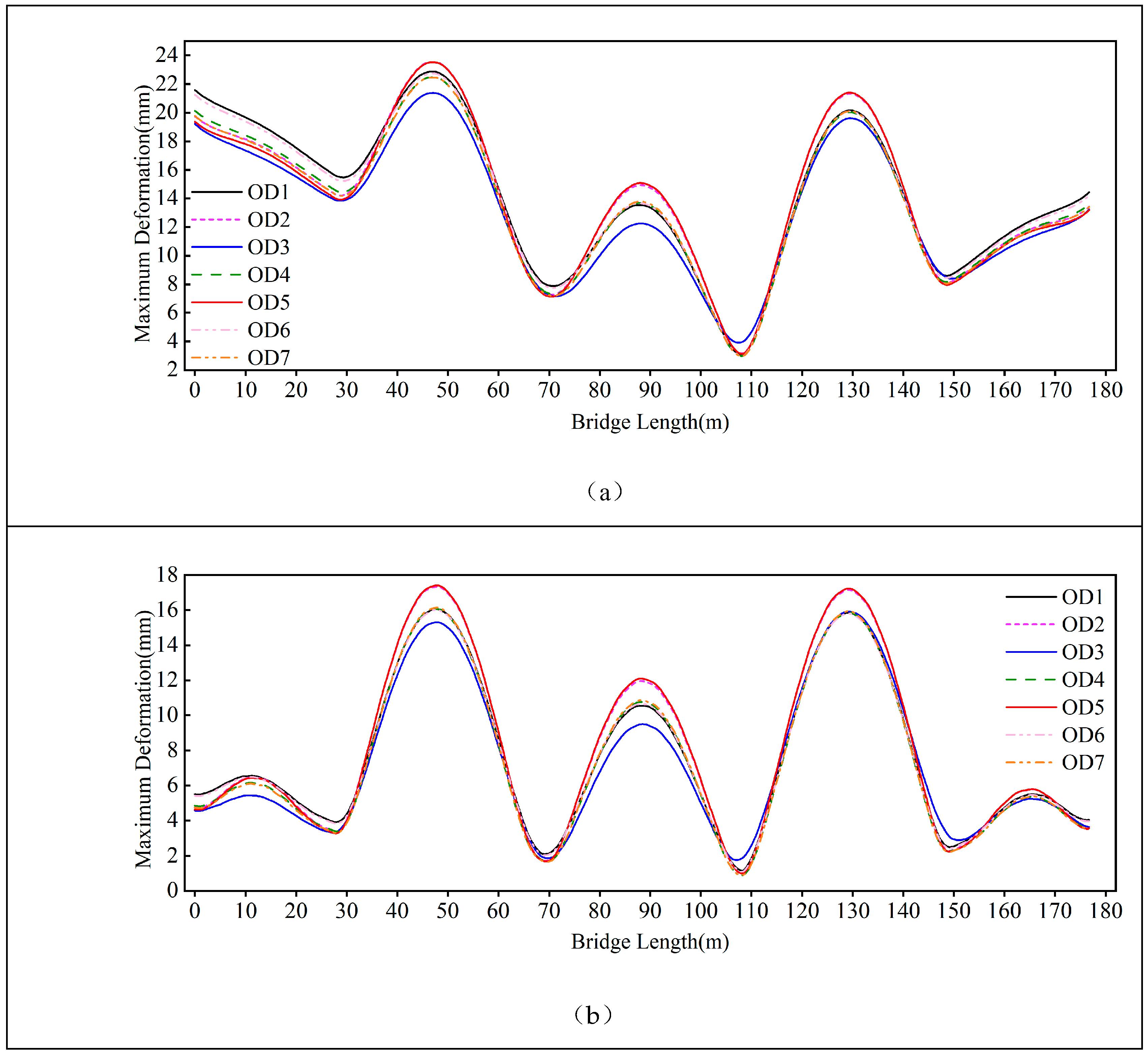
Under the conditions of dead load and an overall temperature change of 9℃, the comparison results of the maximum stress at each support section and the overall bridge displacement for the seven schemes are shown in Figure 39 and Figure 40. From Figure 39, it can be observed that under the overall temperature change condition, the OD4 scheme, which considers both cross-sectional shape parameters and longitudinal bridge parameters, exhibits the minimum stress at each support under both temperature change environments and dead load. In contrast, the OD3 scheme, which only optimizes the stiffening rib parameters, shows the highest stress. The OD7 scheme, which optimizes all parameters, has greater stress than the OD4 scheme under the temperature rise condition, while its stress is close to the OD4 scheme under the temperature drop condition. The comparative study of the seven parameter coupling schemes indicates that optimizing only the longitudinal bridge parameters and cross-sectional shape parameters, without adjusting the stiffening rib layout, yields the best stress improvement effect.
From Figure 40, it can be seen that under the overall temperature drop condition, the deformation distribution pattern of the seven parameter coupling schemes is the same, with larger deformation at mid-span and smaller deformation at supports. The deformation difference at the same position among different schemes remains within 4mm. Among them, the OD5 scheme, which considers both stiffening rib and longitudinal bridge parameter optimization, shows large deformation fluctuation along the bridge length, resulting in a relatively poor deformation improvement effect. The OD3 scheme, which only optimizes the stiffening rib parameters, exhibits the smallest deformation variation and the lowest average displacement, indicating a relatively better deformation improvement effect.
Figure 39.
Maximum Equivalent Stress at the Support Section for Various Parameter Coupling Schemes under Temperature Change Conditions. (a) Overall Heating Condition. (b) Overall Cooling Condition.
Figure 39.
Maximum Equivalent Stress at the Support Section for Various Parameter Coupling Schemes under Temperature Change Conditions. (a) Overall Heating Condition. (b) Overall Cooling Condition.
Figure 40.
Maximum Displacement at Various Locations of the Entire Bridge for Different Parameter Coupling Schemes under Temperature Change Conditions. (a) Overall Heating Condition. (b) Overall Cooling Condition.
Figure 40.
Maximum Displacement at Various Locations of the Entire Bridge for Different Parameter Coupling Schemes under Temperature Change Conditions. (a) Overall Heating Condition. (b) Overall Cooling Condition.
Based on the comparative analysis of various parameter coupling schemes and considering their effects on improving the stress and deformation of curved steel box girders, the following optimized structural design for curved steel box girders is proposed:
The cross-section should have four webs, with the web thickness not less than that of the top and bottom plates.
The height-to-width ratio λ of the cross-section should not be less than 0.15; a single-box three-cell section is recommended.
Diaphragms near the supports should be densely arranged, with three equally spaced diaphragms; the middle diaphragm is the support diaphragm. The spacing of densely arranged diaphragms should be 0.5 to 1m, and the thickness of the support diaphragm should be at least 2mm greater than that of the middle diaphragm. Diaphragms should be evenly spaced at intervals of 2.5 to 3.5m.
In girder segments near the mid-span, diaphragms should be arranged with non-uniform spacing, decreasing gradually from the mid-span towards the ends. The maximum spacing should not exceed 3.5m, and the minimum spacing should not be less than 1m.
The perforation rate ρ of the manholes in the diaphragms should be ρ≤0.4, and the smaller the perforation rate, the better, provided the manhole meets the passage requirements. Manholes should be symmetrically centered.
Transverse stiffeners should be set on the bottom plate near each support, with no more than four stiffeners. The distance from the transverse stiffeners to the support diaphragm should be determined by Formula 9.
The longitudinal stiffeners on the top and bottom plates of the curved steel box girder should have as large a height-to-width ratio as possible under permissible conditions; web stiffeners should be set according to standard requirements and should not be overly arranged.
Support stiffeners usually adopt plate ribs, with specific dimensions determined by the size of the bearing pad. Assuming the transverse and longitudinal dimensions of the bearing pad are b and h, respectively, the eccentricity B of the support stiffeners relative to the centerline of the support should be 0.25b, and the longitudinal width a should be 0.3h.
7. Conclusion
(1) This study highlights the complex interaction of vertical, horizontal, and longitudinal temperature gradients on the structural response of continuous curved steel box girders. It was found that local stresses at the septum near the mid-span fulcrum are significantly intensified under the combined effects of thermal and mechanical loads, with stress potentially amplifying to twice that of the girder’s surface. Improving the performance of the septum at critical fulcrum points can significantly reduce temperature-induced stresses in the surrounding area.
(2) Cross-sectional parameters significantly affect the thermal behavior of the girder. Introducing a central axis sternum into the section enhances thermal response sensitivity, with an increase in septum thickness from 10 mm to 20 mm leading to a 33% reduction in temperature-induced stress. The aspect ratio of the section is also crucial; as it increases from 0.1 to 0.2, there is a significant reduction in both deformation (45.7%) and stress (36.6%), assuming the girder height remains constant.
(3) Longitudinal structural parameters are crucial in controlling thermal effects. A width-to-span ratio of approximately 0.36 ensures minimal deformation and stress reduction as the ratio decreases. Different restraint methods at identical girder positions can lead to stress differentials exceeding 90 MPa. Additionally, a longitudinal gradient greater than 4% can exacerbate local stresses under thermal loading.
(4) The arrangement of stiffening ribs is essential for managing thermal stress. Increasing the curved stiffness of longitudinal stiffeners on the top and bottom plates, adding transverse stiffeners at the edges of the support plate, and optimizing the width and eccentricity of support stiffeners to 30% and 25% of the support plate size, respectively, can alleviate local temperature-induced stresses. However, variations in the number of longitudinal and transverse stiffeners, as well as changes in sectional parameters, do not significantly impact the thermal performance of the continuous curved steel box girder.
(5) Without altering the external contour dimensions of continuous curved steel box girders, this paper proposes design recommendations to mitigate the effects of temperature. These recommendations comprehensively consider the impact of cross-sectional shape parameters, longitudinal structural parameters, and stiffening rib parameters on improving the stress distribution and deformation characteristics of curved steel box girders. They offer valuable insights for the optimization design of continuous curved steel box girder bridges.
Author Contributions
Methodology, S.W. and G.Z.; validation, S.W. and H.L.; formal analysis, H.L., Y.W. and B.Z.; writing—original draft preparation, S.W., Y.W., B.Z. And X.H.; writing—review, S.W., G.Z., X.H. and Z.Y.; editing, H.L., X.H. and Z.Y. All authors have read and agreed to the published version of the manuscript.
Data Availability Statement
Not applicable.
Acknowledgments
Natural Science Basic Research Program of Shaanxi (Program No.2022JC-23), Innovation Capability Support Program of Shaanxi (Program No.2023-CX-TD-38), Fundamental Research Funds for the Central Universities, CHD(300102214401, 300102214903).
Conflicts of Interest
The authors declare no conflict of interest.
References
- Ding, Y.H.; Zhang, G.; Zhao, X.C.; et al. Shear performance of horizontally curved steel box bridge girders under hydrocarbon fire exposure conditions: numerical investigation and design implications. Thin-walled Structures 2024. [Google Scholar] [CrossRef]
- Zhang, G.; Li, X.Y.; Tang, C.H.; et al. Behavior of steel box bridge girders subjected to hydrocarbon fire and bending-torsion coupled loading. Engineering Structures 2023, 296, 116906. [Google Scholar] [CrossRef]
- Song, C.J.; Zhang, G.; Lu, Z.L.; et al. Fire resistance tests on polypropylene -fiber-reinforced prestressed concrete box bridge girders. Engineering Structures 2023, 282, 115800. [Google Scholar] [CrossRef]
- Zhang, G.; Zhao, X.C.; Song, C.J.; et al. Summary of fire science and safety guarantee technology of bridge structure. Journal of traffic and transportation engineering 2023, 23, 94–113. [Google Scholar] [CrossRef]
- Li, X.Y.; Zhang, G.; Song, C.J.; et al. Method for improving fire resistance of continuous bending steel box girder in complex environment. China journal of highway and transport 2022, 35, 192–204. [Google Scholar] [CrossRef]
- Wang, S.C.; Zhang, G.; Li, J.; et al. Temperature Response of Double-Layer Steel Truss Bridge Girders. Buildings 2023, 13, 2889. [Google Scholar] [CrossRef]
- Song, C.J.; Zhang, G.; Li, X.Y.; Kodur, V. Experimental study on failure mechanism of steel-concrete composite bridge girders under fuel fire exposure. Engineering Structures 2021, 247, 113230. [Google Scholar] [CrossRef]
- Brownjohn J., M.W.; Koo, K.Y.; Scullion, A.; et al. Operational deformations in long-span bridges. Structure and Infrastructure Engineering 11, 556–574. [CrossRef]
- Wen, W.Q.; Li, S.W.; Yan, A.G.; et al. Numerical analysis on the time-varying temperature field distributio patterns of ballastless track steel-concrete composite box girders at ambient temperature based on field measurements. Adv. Bridge Eng. 2, 1–16. [CrossRef]
- Zhou, G.D.; Yi, T.H. Thermal Load in Large-Scale Bridges: A State-of-the-Art Review. International Journal of Distributed Sensor Networks 2013, 9, 217983. [Google Scholar] [CrossRef]
- Lei, X.; Jiang, H.; Wang, J. Temperature Effects on Horizontally Curved Concrete Box-Girder Bridges with Single-Column Piers. Journal of Aerospace Engineering 2019, 32, 04019008. [Google Scholar] [CrossRef]
- Lin, J.; Briseghella, B.; Xue, J.; et al. Temperature Monitoring and Response of Deck-Extension Side-By-Side Box Girder Bridges. Journal of Performance of Constructed Facilities 2020, 34, 04019122. [Google Scholar] [CrossRef]
- Wang, J.F.; Zhang, J.T.; Xu, R.Q.; et al. Evaluation of Thermal Effects on Cable Forces of a Long-Span Prestressed Concrete Cable–Stayed Bridge. Journal of Performance of Constructed Facilities 2019, 33, 04019072. [Google Scholar] [CrossRef]
- Miao, C.Q.; Shi, C.H. Study on temperature gradient and temperature influence of flat steel box girder of long-span suspension bridge. China Science: Technical Science 2013, 10, 1155–1164. [Google Scholar] [CrossRef]
- Zhou, L.R.; Chen, L.; Xia, Y.; et al. Temperature-Induced Structural Static Responses of a Long-Span Steel Box Girder Suspension Bridge. Journal of Zhejiang University-Science A 2020, 21, 580–592. [Google Scholar] [CrossRef]
- Zhang, Y.P.; Yang, N.; Li, C.X. Analysis of sunshine temperature field of steel box girder without pavement. Engineering mechanics 2011, 28, 156–162. [Google Scholar] [CrossRef]
- Wang, Z.W.; Zhang, W.M.; Zhang, Y.F.; et al. Temperature prediction of flat steel box girders of long-span bridges utilizing In situ environmental parameters and machine learning. Journal of Bridge Engineering 27, 04022004. [CrossRef]
- Tao, T.; Wang, H.; Zhu, Q.X.; et al. Long-term temperature field of steel-box girder of a long-span bridge: Measurement and simulation. Engineering Structures 2021, 236, 111924. [Google Scholar] [CrossRef]
- Huang, X.; Zhu, J.; Jiang, S.J.; et al. Temperature Field Characteristics of Flat Steel Box Girders Based on In Situ Field Measurement and Numerical Simulation. Journal of Bridge Engineering 2023, 28, 1.1–1.15. [Google Scholar] [CrossRef]
- Huang, X.; Zhu, J.; Li, Y.L. Temperature analysis of steel box girder considering actual wind field. Engineering Structures 2021, 246, 113020. [Google Scholar] [CrossRef]
- Xu, Z.Y. Temperature field and its effect analysis of curved steel box girder bridge. Master’s Thesis, Zhejiang University, Hangzhou, China, 2016. [Google Scholar]
- Wan, L. Study on spatial stress behavior of curved steel box girder bridge. Master’s Thesis, Southwest Jiaotong University, Chengdu, China, 2018. [Google Scholar]
- Yang, J.N.; He, X.J.; Yang, J.H.L.; et al. Analysis on Temperature Effect of Asphalt Concrete Paving of S-shaped Curved Steel Box Girder Cable-stayed Bridge. Bridge construction 2020, 50, 37–42. [Google Scholar]
- Wang, Q. Research on Supporting System and Span Ratio of Curved Steel Box Girder Bridge. Master’s Thesis, Dalian University of Technology, Dalian, China, 2020. [Google Scholar]
- Kim S., H.; Park S., J.; Wu, J.; et al. Temperature Variation in Steel Box Girders of Cable-Stayed Bridges During Construction. Journal of Constructional Steel Research 2015, 112, 80–92. [Google Scholar] [CrossRef]
- Chen, B.; Zheng, J.; Wang, J.P. Research progress on temperature effect of bridge structure. Journal of wuhan university of technology 2010, 5. [Google Scholar] [CrossRef]
Figure 1.
Represents the cross-section of the curved steel box girder model (unit: mm).
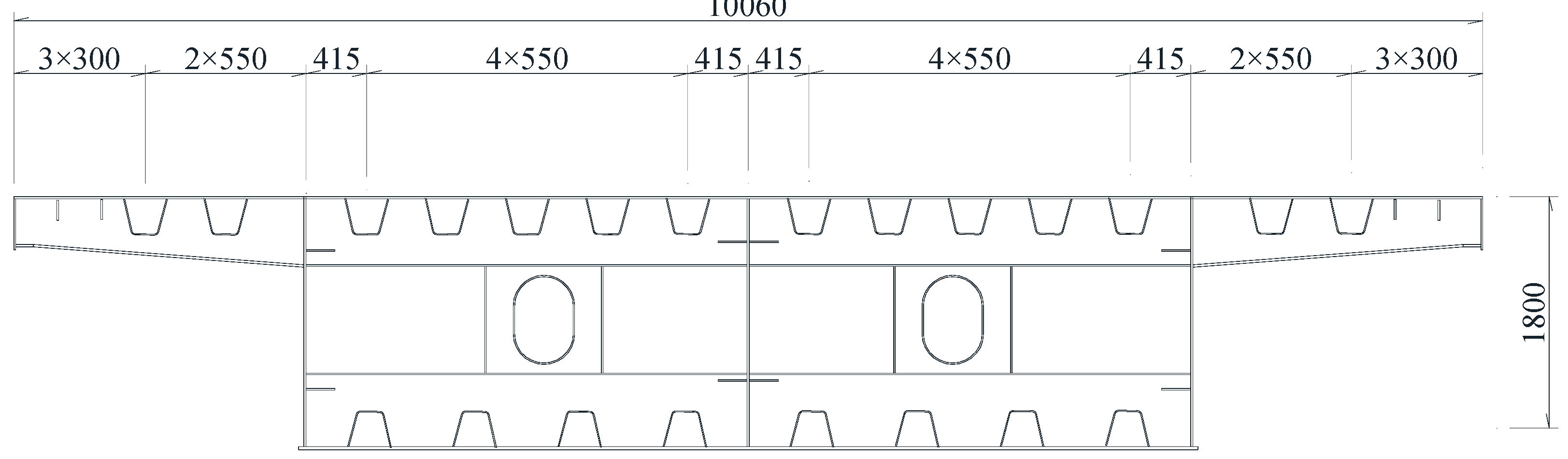
Figure 2.
Steel box girder model.
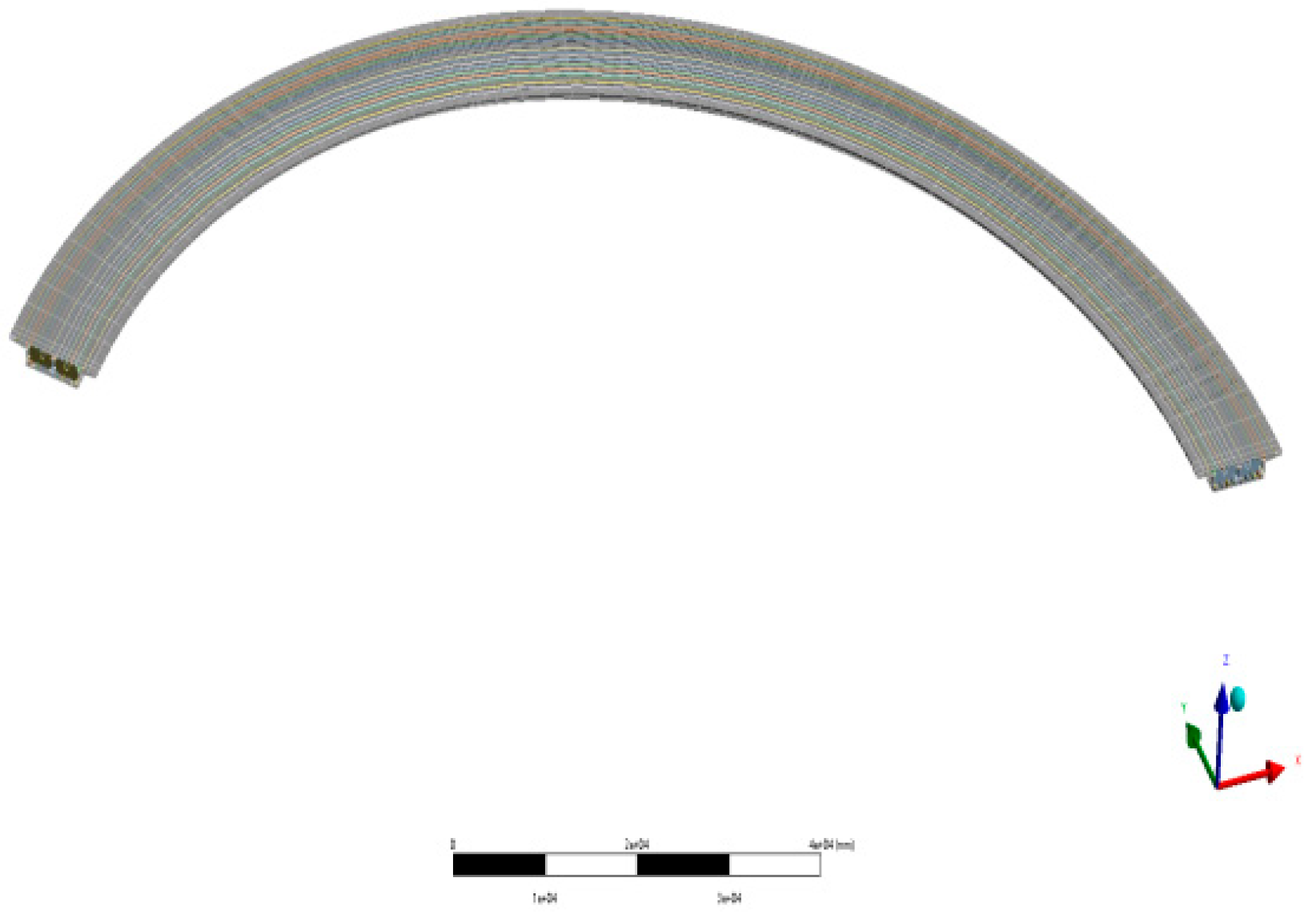
Figure 3.
Support Arrangement.
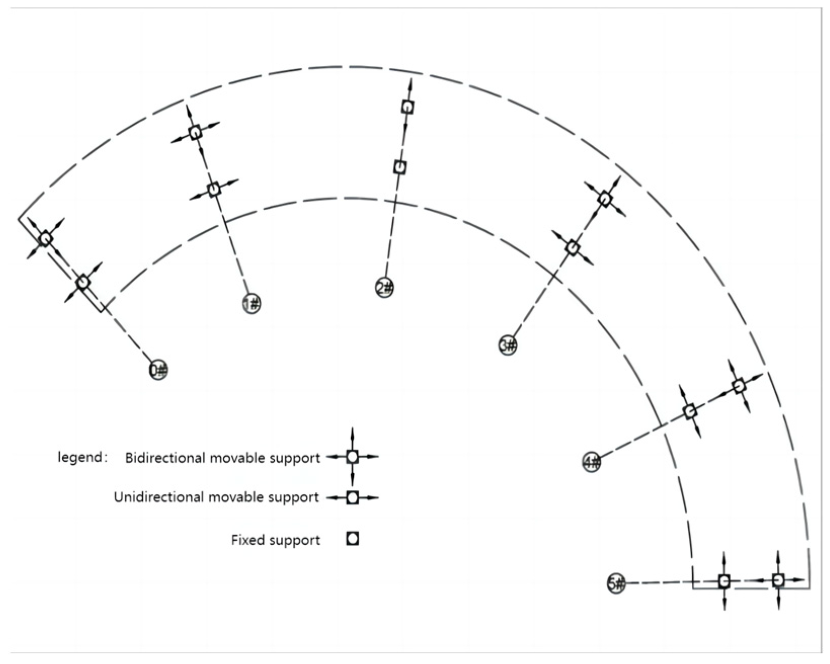
Figure 4.
Arrangement of temperature measurement points (unit: mm).
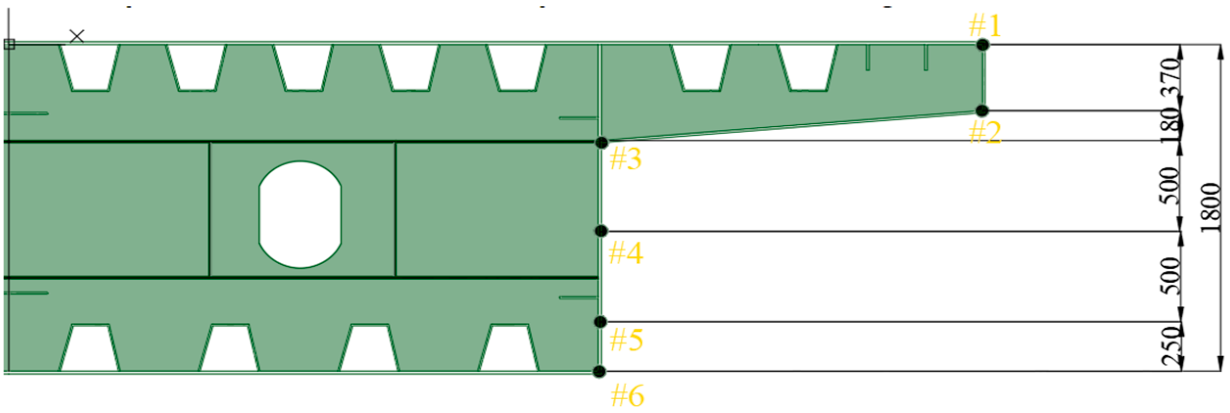
Figure 5.
Measured 13:00 and 15:00 temperatures vs. simulated temperatures.
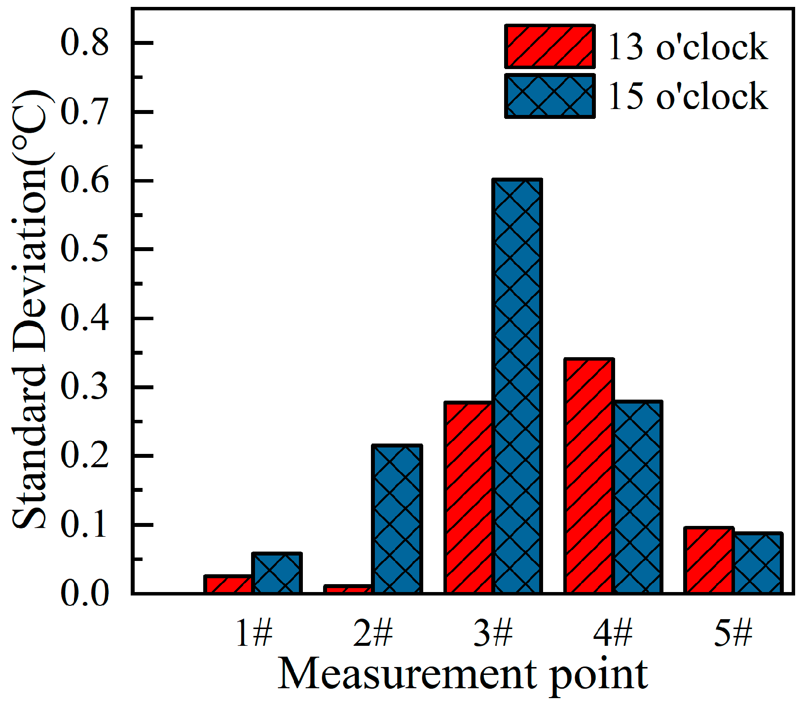
Figure 6.
Standard deviation of measured and simulated data.
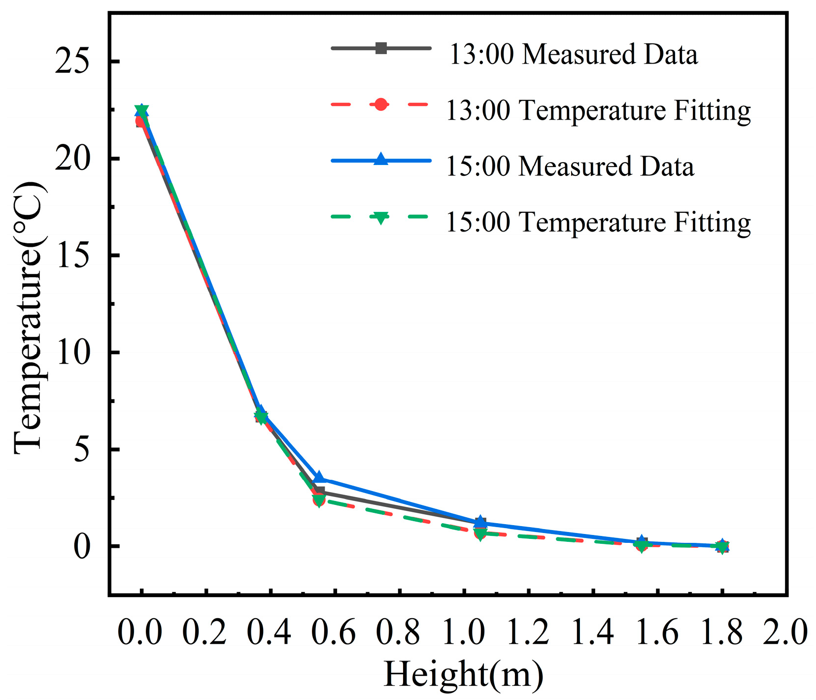
Figure 7.
The relationship between maximum equivalent stress and the number of chambers.
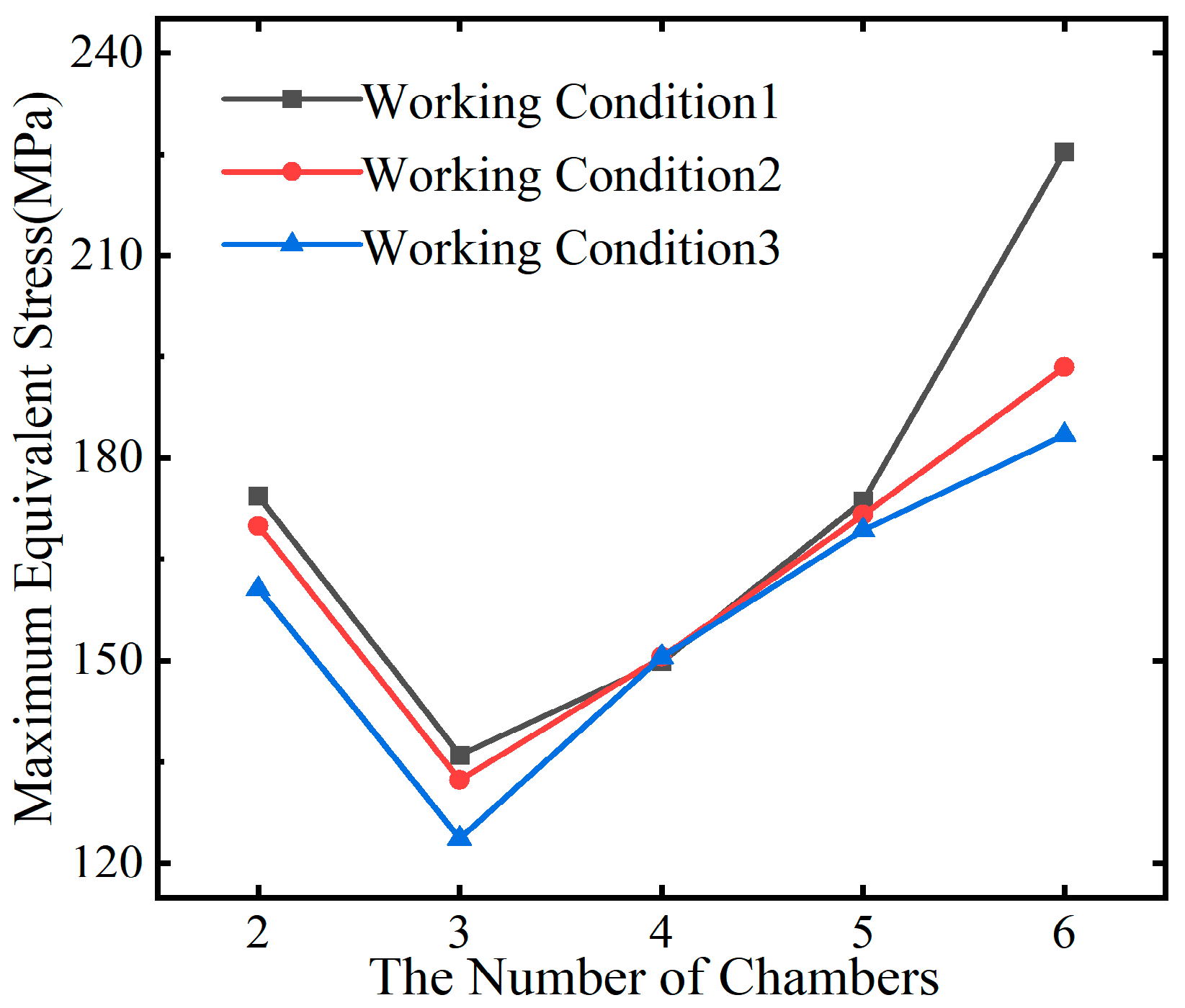
Figure 8.
The relationship between maximum shear stress and the number of chambers.
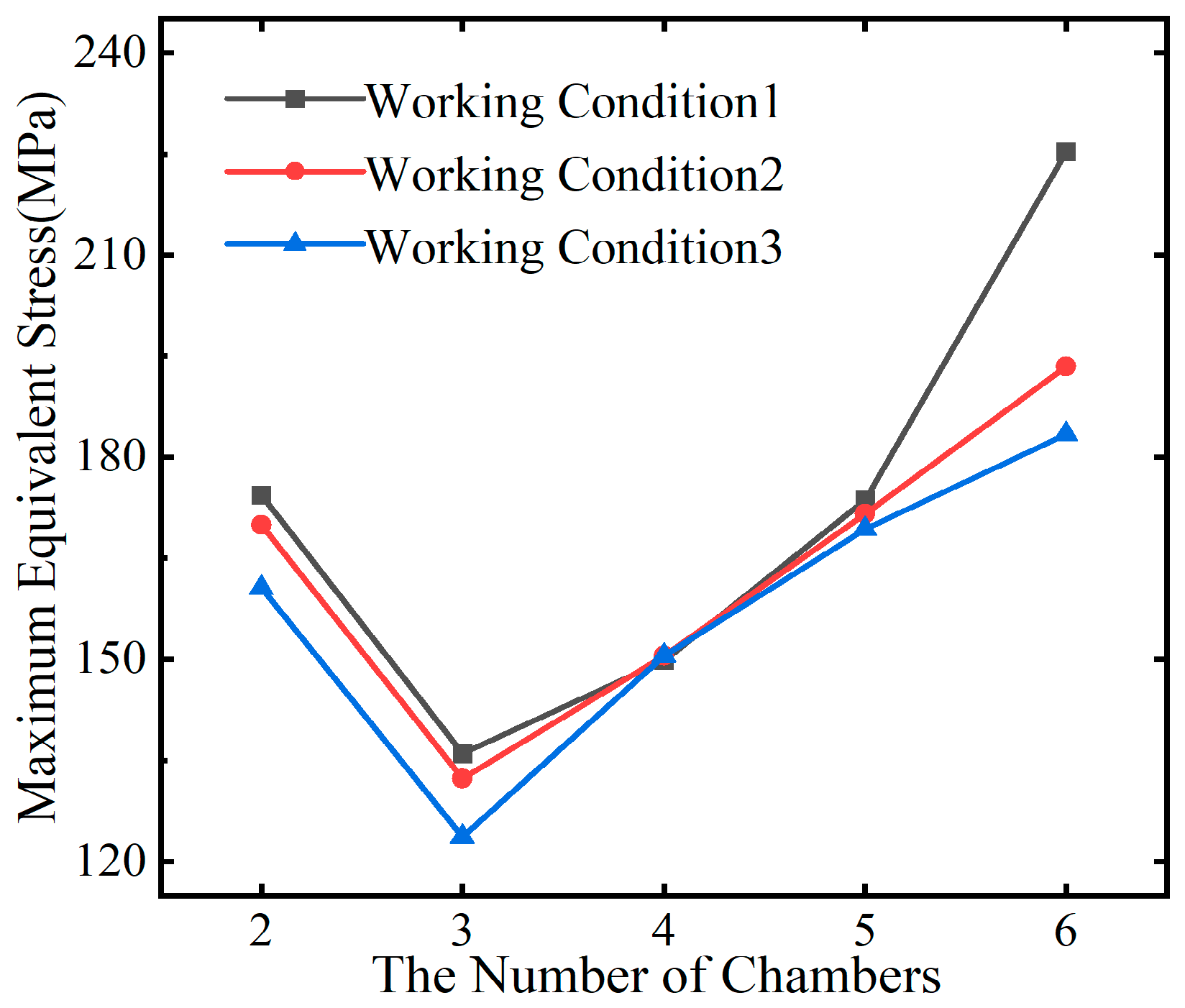
Figure 9.
The relationship between maximum deformation and the number of chambers.
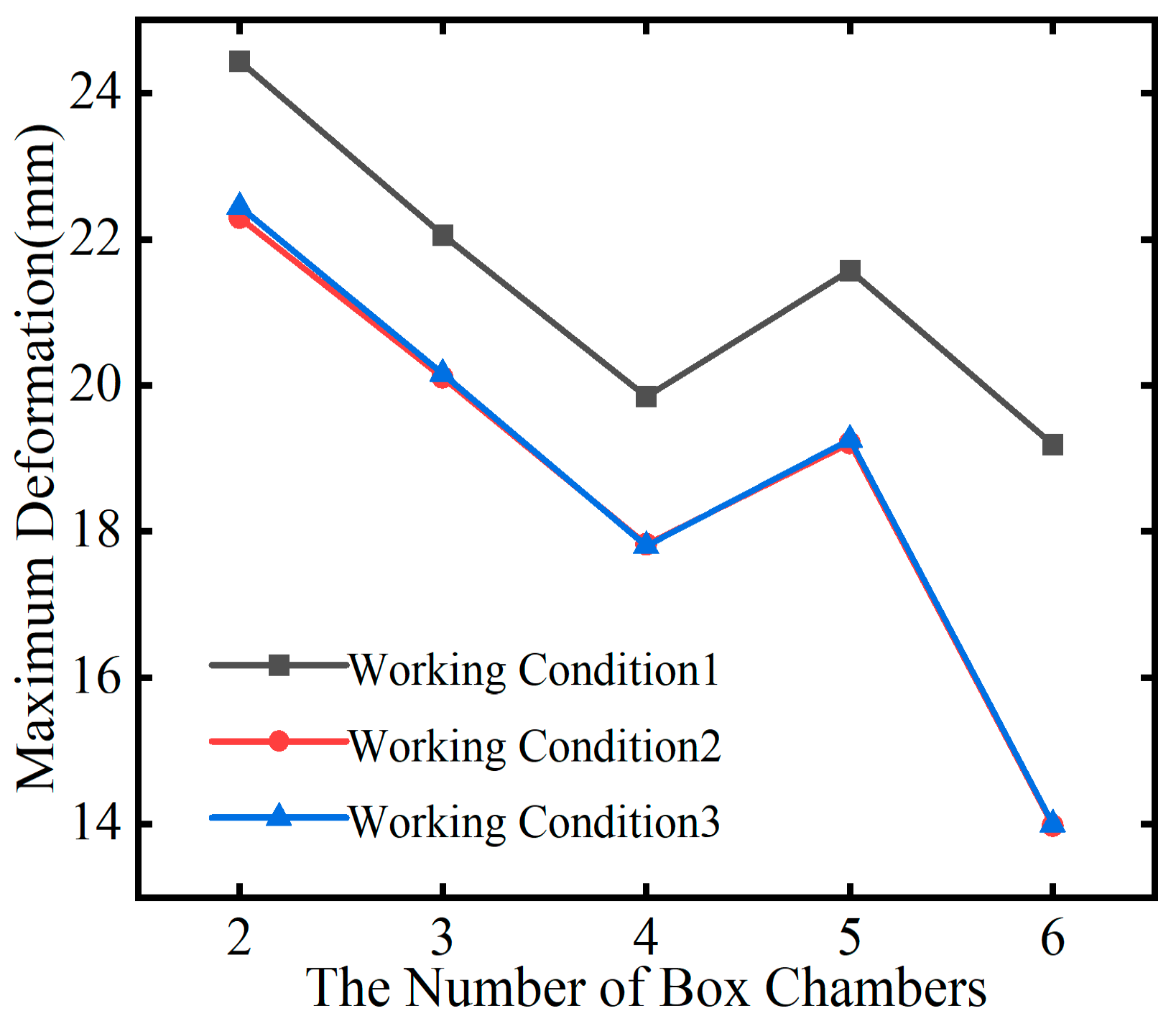
Figure 10.
Septum thickness and ultimate stress.
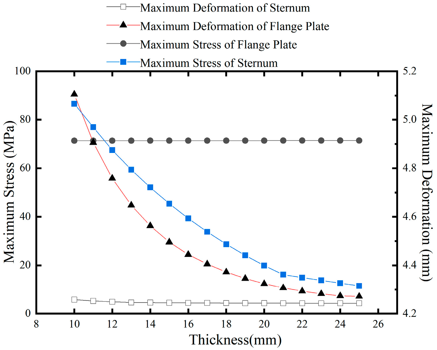
Figure 11.
Thickness of plate and maximum deformation.
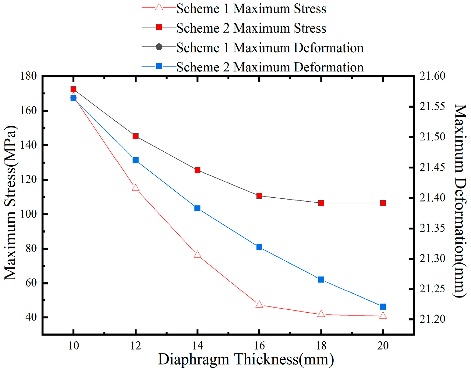
Figure 19.
Span number and maximum equivalent stress under positive radial gradient.
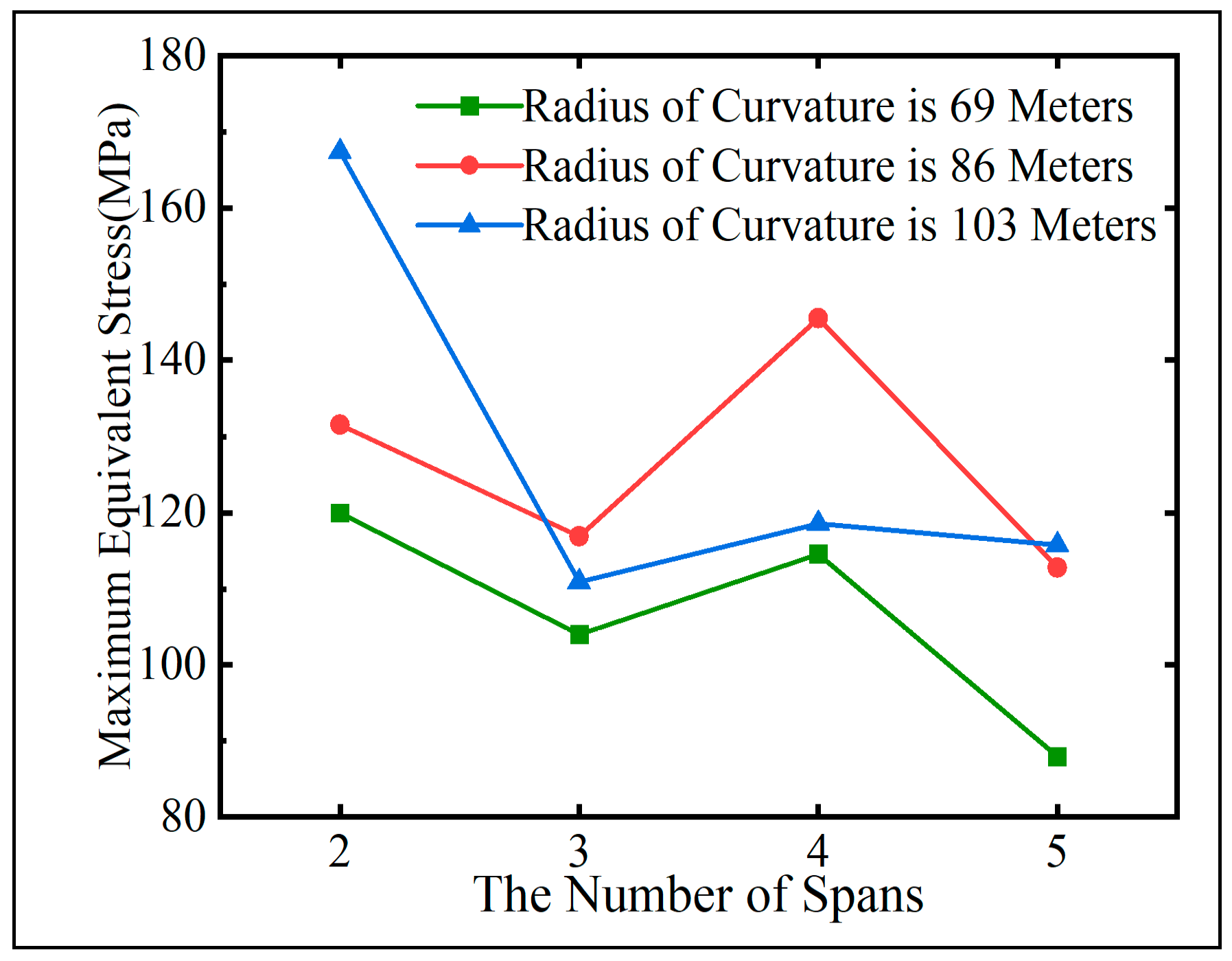
Figure 20.
Span number and maximum equivalent stress under negative radial gradient.
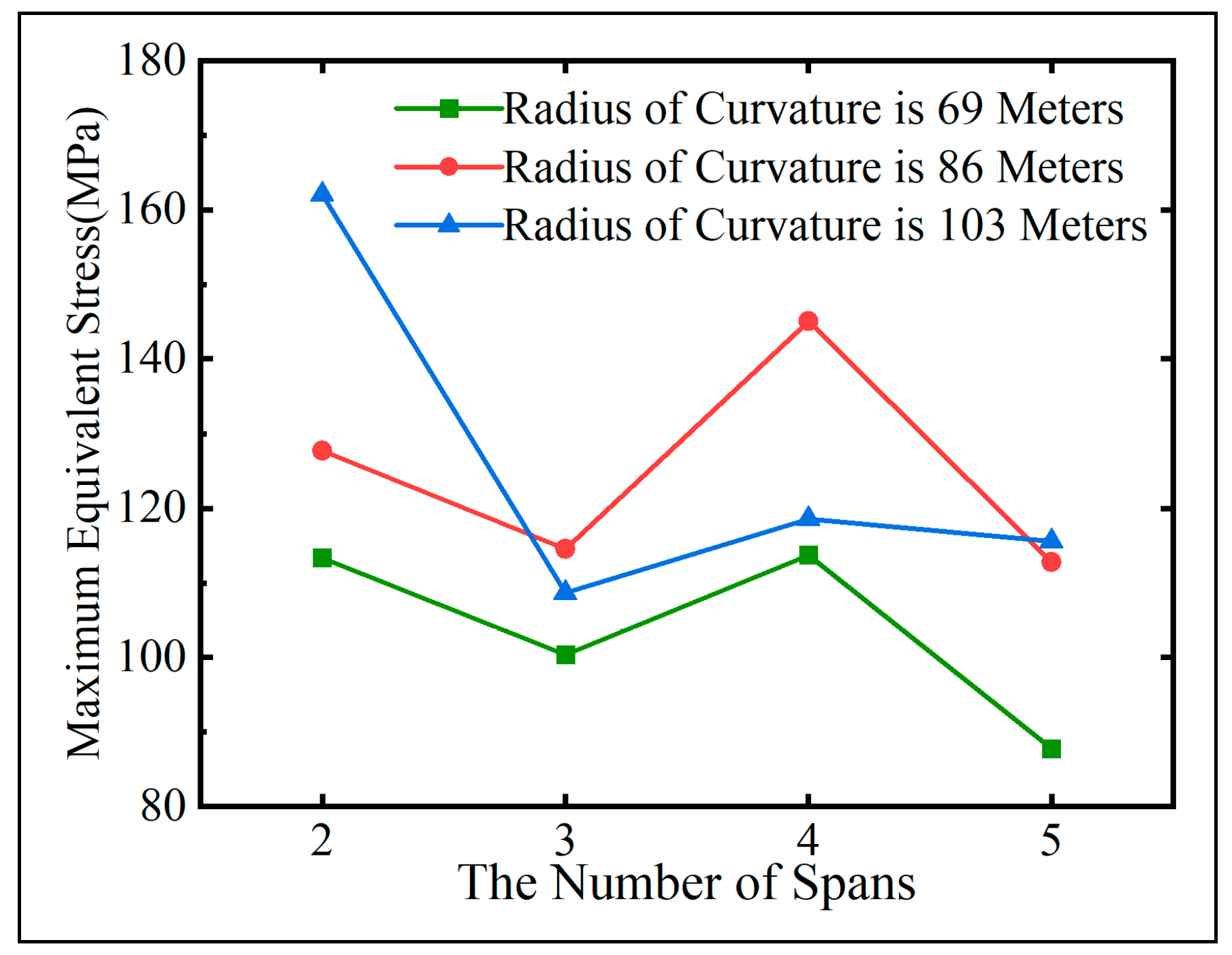
Figure 21.
Span number and maximum displacement under positive radial gradient.
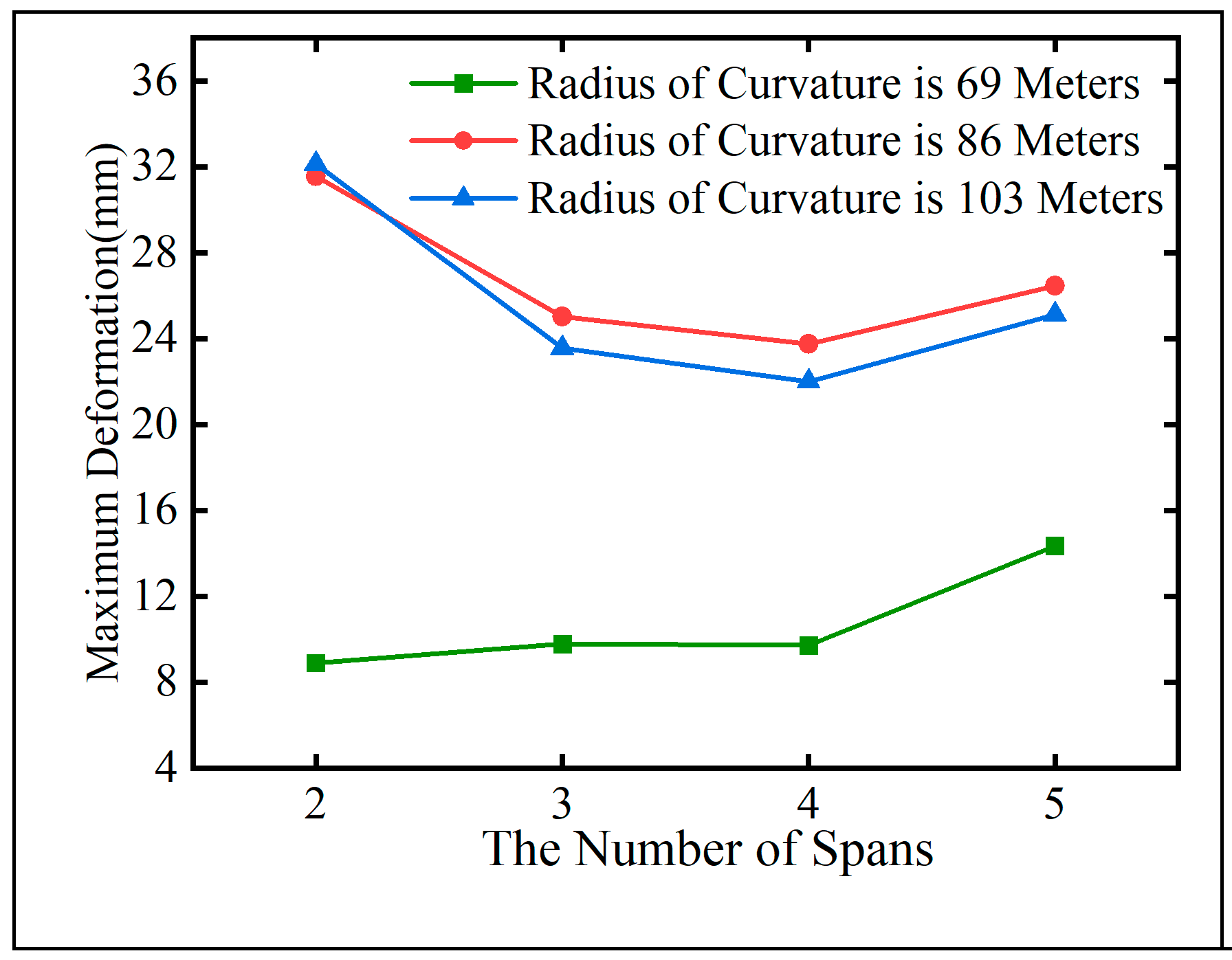
Figure 22.
Span number and maximum displacement under negative radial gradient.
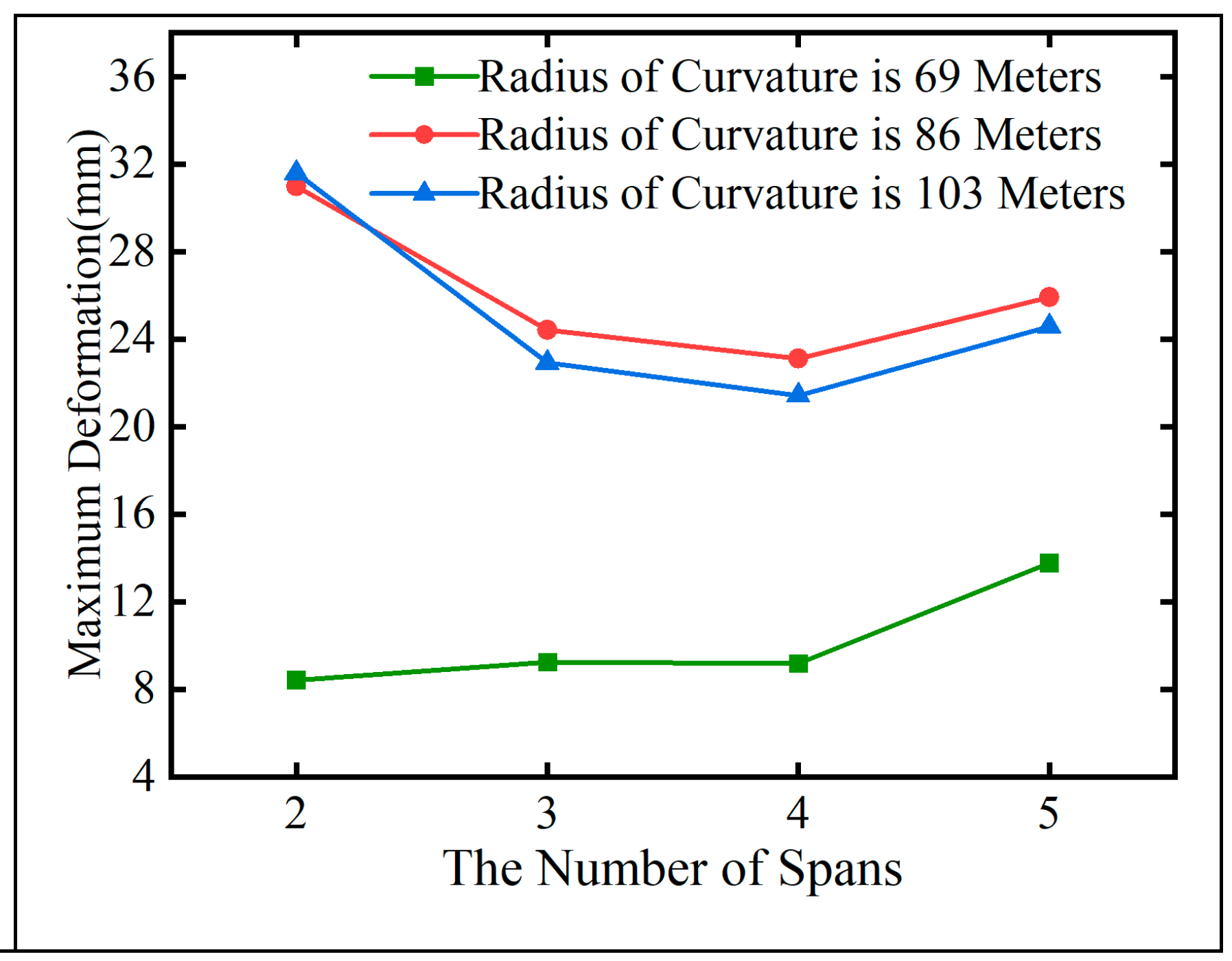

Table 1.
Steel box girder model stiffening rib component reinforcement.
| Name | Thickness x length (mm) | Material |
|---|---|---|
| Closed-cell stiffening rib | as shown in the figure | Q345qD |
| Open reinforcement on top and bottom plates | 12×140 | Q345qD |
| Horizontal stiffening rib in web | 10×200 | Q345qD |
Table 2.
Thermal Boundary Condition Imposition Program.
| Application location | Temperatures | Radiation rate | Convection coefficient hc (Unit W/m2) |
|---|---|---|---|
| Upper surface of top plate | 59/59.6/60.2 | 0.88 | 13.096 |
| Outer surface of outer web | 0 | 0.5 | 12.096 |
| Outer surface of inner web | 0 | 0.5 | 12.096 |
| Lower surface of bottom plate | 0 | 0.5 | 12.096 |
| Lower surface of flange plate | 0 | 0.5 | 10.596 |
| Surface of diaphragm | 0 | 0.5 | 3.5 |
Table 3.
The mode of temperature.
| Temperature gradient type | Load case | Content |
|---|---|---|
| Vertical temperature gradient | Working condition 1 | The top surface temperature is raised from 38 ℃ to 47 ℃ |
| Longitudinal temperature gradient | Working condition 2 | It gradually increases by 9 ℃ along the Y-axis direction of the overall coordinate system, with the lowest temperature of 38 ℃ and the highest temperature of 47 ℃. |
| Transverse temperature gradient | Working condition 3 | Compared with the inner edge, the outer edge is linearly increased by 9 ℃ in the radial direction, the inner edge temperature is 38 ℃, and the outer edge temperature is 47 ℃. |
Table 4.
Structural parameters of curved steel box girder.
| Model number | Widthb(m) | Highth(m) | aspect ratio λ |
Curvature radius(m) | Single span(m) | Central angle | Ratio of edge span to mid span | Cross section type |
|---|---|---|---|---|---|---|---|---|
| 1 | 7 | 1.8 | 0.26 | 86 | 45 | 90° | 1:1:1 | Single box double room |
| 2 | 8 | 1.8 | 0.23 | 86 | 45 | 90° | 1:1:1 | Single box double room |
| 3 | 9 | 1.8 | 0.20 | 86 | 45 | 90° | 1:1:1 | Single box double room |
| 4 | 10 | 1.8 | 0.18 | 86 | 45 | 90° | 1:1:1 | Single box double room |
| 5 | 11 | 1.8 | 0.16 | 86 | 45 | 90° | 1:1:1 | Single box double room |
| 6 | 12 | 1.8 | 0.15 | 86 | 45 | 90° | 1:1:1 | Single box double room |
| 7 | 13 | 1.8 | 0.14 | 86 | 45 | 90° | 1:1:1 | Single box double room |
| 8 | 14 | 1.8 | 0.13 | 86 | 45 | 90° | 1:1:1 | Single box double room |
| 9 | 15 | 1.8 | 0.12 | 86 | 45 | 90° | 1:1:1 | Single box double room |
| 10 | 16 | 1.8 | 0.11 | 86 | 45 | 90° | 1:1:1 | Single box double room |
| 11 | 17 | 1.8 | 0.11 | 86 | 45 | 90° | 1:1:1 | Single box double room |
| 12 | 18 | 1.8 | 0.10 | 86 | 45 | 90° | 1:1:1 | Single box double room |
Table 5.
Plane parameter analysis model of continuous curved steel box bridge girder structure.
| Group | Model Number | Curvature radius R(m) |
Number of spans n | Bridge length L (m) |
central angle θ (°) |
Ratio of edge span to mid span |
|---|---|---|---|---|---|---|
| A | A1 | 69 | 5 | 138 | 115 | 0.8:1:1:1:0.8 |
| A2 | 69 | 4 | 108 | 90 | 0.8:1:1:0.8 | |
| A3 | 69 | 3 | 78 | 65 | 0.8:1:0.8 | |
| A4 | 69 | 2 | 60 | 50 | 1:1 | |
| B | B1 | 86 | 5 | 207 | 138 | 0.8:1:1:1:0.8 |
| B2 | 86 | 4 | 162 | 108 | 0.8:1:1:0.8 | |
| B3 | 86 | 3 | 117 | 78 | 0.8:1:0.8 | |
| B4 | 86 | 2 | 90 | 60 | 1:1 | |
| C | C1 | 103 | 5 | 207 | 115 | 0.8:1:1:1:0.8 |
| C2 | 103 | 4 | 162 | 90 | 0.8:1:1:0.8 | |
| C3 | 103 | 3 | 117 | 65 | 0.8:1:0.8 | |
| C4 | 103 | 2 | 90 | 50 | 1:1 |
Table 6.
Width-span ratio parameters of continuous bending steel box model.
| Model number | Radius of curvature R (m) |
Width-span ratio δ | Total length of bridge L (m) |
Central angleθ (°) |
Side-to-side span ratio | Single span span(m) |
|---|---|---|---|---|---|---|
| D1 | 69 | 0.46 | 108 | 90 | 1:1:1:1:1 | 21.6 |
| D2 | 69 | 0.37 | 108 | 90 | 1:1:1:1 | 27 |
| D3 | 69 | 0.28 | 108 | 90 | 1:1:1 | 36 |
| E1 | 60 | 0.47 | 84 | 80 | 1:1:1:1 | 21 |
| E2 | 60 | 0.36 | 84 | 80 | 1:1:1 | 28 |
| E3 | 60 | 0.24 | 84 | 80 | 1:1 | 42 |
Table 7.
Decrease of stress and deformation caused by δ change in group D.
| δ change | Single span reduction | Temperature condition | Maximum principal stress reduction | Maximum equivalent stress reduction | Maximum deformation reduction |
|---|---|---|---|---|---|
| 0.36→0.47 | 7 m | overall heating 9°C | 13.32% | 7.44% | 20.71% |
| 0.24→0.36 | 14 m | 40.83% | 43.28% | 59.32% | |
| 0.36→0.47 | 7 m | Overall cooling 9℃ | 37.37% | 20.24% | 40.22% |
| 0.24→0.36 | 14 m | 14.86% | 34.19% | 69.80% |
Table 8.
Decrease of stress and deformation caused by δ change in group E.
| δ changed | Single span reduction | Temperature condition | Maximum principal stress reduction | Maximum equivalent stress reduction | Maximum deformation reduction |
|---|---|---|---|---|---|
| 0.36→0.47 | 7m | overall heating 9°C | 13.32% | 7.44% | 20.71% |
| 0.24→0.36 | 14m | 40.83% | 43.28% | 59.32% | |
| 0.36→0.47 | 7m | Overall cooling 9℃ | 37.37% | 20.24% | 40.22% |
| 0.24→0.36 | 14m | 14.86% | 34.19% | 69.80% |
Table 9.
Support layout scheme.
| Plan | Fixed support number | Support eccentricity(m) |
|---|---|---|
| Z1 | 5 | 2.4 |
| Z2 | 6 | 2.4 |
| Z3 | 3 | 2.4 |
| Z4 | 4 | 2.4 |
| Z5 | 3, 5 | 2.4 |
| Z6 | 4, 6 | 2.4 |
| Z7 | 3, 7 | 2.4 |
| Z8 | 4, 8 | 2.4 |
Table 10.
Contents of Parameter Optimization Design.
| Parameter type | Parameters | Parameter optimization design |
|---|---|---|
| Cross-sectional shape parameters | Number of chambers | Adopt single box with three chambers cross-section |
| Transverse diaphragm thickness | The thickness of the support diaphragm is 4mm greater than that of the intermediate diaphragm. | |
| Cross-sectional steel plate thickness | The web thickness is 4mm greater than the thickness of the top and bottom plates. | |
| Longitudinal bridge structural parameters | Intermediate diaphragm spacing | Intermediate diaphragm spacing is set at 3.5 meters. |
| Support diaphragm spacing | The spacing between the support diaphragm and the adjacent intermediate diaphragms is set at 0.5 meters. | |
| Support arrangement | Use a simply supported system with dual supports, fixed at the central support on the inner side of the curve. | |
| Stiffening rib | Longitudinal stiffening rib | The vertical height of the longitudinal stiffening ribs on the top and bottom plates is increased by 2 centimeters. |
| Transverse stiffening rib | The spacing between transverse stiffening ribs on the bottom plate and the support crossbeam is equal to the spacing between transverse stiffening ribs on the bottom plate, determined according to formula 9. | |
| Support stiffening rib | The side length of the bearing pad is denoted as l.The eccentricity b of the support stiffening rib satisfies b/l=0.25. The width a of the support stiffening rib satisfies a/l=0.3. The thickness of the support stiffening rib is 4mm greater than that of the support diaphragm. |
Table 11.
Multi-Parameter Coupling Schemes.
| Scheme ID | Parameters |
|---|---|
| OD1 | Cross-sectional shape parameters |
| OD2 | Longitudinal bridge structural parameters |
| OD3 | Stiffening rib |
| OD4 | Cross-sectional shape parameters + longitudinal bridge structural parameters |
| OD5 | Stiffening rib + longitudinal bridge structural parameters |
| OD6 | Cross-sectional shape parameters + stiffening rib |
| OD7 | Cross-sectional shape parameters + longitudinal bridge structural parameters + stiffening rib |
Disclaimer/Publisher’s Note: The statements, opinions and data contained in all publications are solely those of the individual author(s) and contributor(s) and not of MDPI and/or the editor(s). MDPI and/or the editor(s) disclaim responsibility for any injury to people or property resulting from any ideas, methods, instructions or products referred to in the content. |
© 2024 by the authors. Licensee MDPI, Basel, Switzerland. This article is an open access article distributed under the terms and conditions of the Creative Commons Attribution (CC BY) license (http://creativecommons.org/licenses/by/4.0/).
Copyright: This open access article is published under a Creative Commons CC BY 4.0 license, which permit the free download, distribution, and reuse, provided that the author and preprint are cited in any reuse.


