
Submitted:
17 October 2024
Posted:
21 October 2024
You are already at the latest version
Abstract
In this paper, we explore a straightforward two-step method to produce high purity, vertically aligned multi-walled carbon nanotubes (MWCNTs) via chemical vapor deposition (CVD). Two distinct solutions are utilized for this CVD method: a catalytic solution consisting of ferrocene and acetonitrile (ACN), and a carbon source solution with camphor and ACN. The vapors of the catalytic solution inserted in the reaction chamber through external boiling, result in a floating catalyst CVD approach that produces vertically aligned MWCNTs in a consistent manner. MWCNTs are grown in a conventional CVD horizontal reactor, at 850°C under atmospheric pressure, and characterized by Raman spectroscopy, Scanning Electron Microscopy (SEM) and Thermogravimetric Analysis (TGA). Coating the MWCNTs with polymethyl methacrylate (PMMA) while still on the Si substrate, retains the structure and results in a flexible, conductive thin film suitable for electrodes. The film is 62 μm thick and stable in aqueous solutions, capable of withstanding further processes such as electropolymerization with polyaniline, to be used for energy storage applications.
Keywords:
Chemical vapor deposition method
; CNT forests
; Conductive thin films
; CVD
; Electropolymerisation
; Multi-walled carbon nanotubes
; MWCNTs
; PANI
1. Introduction
The demand for versatile electronic devices that are flexible, rollable, wearable, and lightweight with excellent mechanical strength has led researchers to develop advanced materials for flexible electronic applications. Carbon nanotubes (CNTs) are increasingly explored towards this purpose due to their exceptional physical, electrical, and mechanical properties [1]. CNTs are composed of concentric graphitic shells and depending on the synthesis method can be highly oriented (CNT forests), offering a promising solution for the development of flexible thin films that can withstand various deformations while maintaining high performance [2–5].
The conventional method for synthesizing CNT forests is chemical vapor deposition (CVD), which involves the deposition of a metallic catalyst layer on a substrate with specific crystallography, followed by a reduction process to activate the catalyst for CNT growth [6,7]. While CVD has proven to be a highly effective method for CNT synthesis, there are still several challenges to overcome. One of the primary difficulties is the need for a large amount of energy to sustain the high temperatures required, often between 600°C and 1200°C, which can make the process energy and cost-intensive [7–9]. Additionally, the presence of metallic impurities, such as those from the catalyst materials used, can be a significant challenge, as these can alter the properties and performance of the produced nanotubes, necessitating additional purification steps [10–13]. Another challenge is the difficulty in controlling the variables related to the orientation and alignment of the growing nanotubes. Unaligned, randomly oriented nanotubes can limit their potential applications, particularly in areas where precise control over nanotube arrangement is crucial, such as in electronic devices or engineered composites [6,14,15].
Floating catalyst CVD (FC-CVD) methods have been developed by introducing the catalyst precursor (typically a metallocene compound such as ferrocene – Fe (C5H5)2) directly into the reaction chamber along with the carbon source necessary for the CNT growth. The dynamic nature of the floating catalyst, together with the specific crystallography of the substrate, allow the growth of CNT forests, while presenting a simpler approach for CNT manufacturing with fewer impurities compared to pre-deposited catalysts [7,16,17]. Plasma-enhanced floating catalyst chemical vapor deposition is an even more advanced variant that takes advantage of the unique properties of microplasma to further improve the CNT growth process, enhancing the dissociation of the reactant gases, leading to higher growth rates and purity along with improved crystallinity of the nanotubes [18,19]. The synthesis of high-purity CNTs and CNT forests through this method necessitates specialized equipment and sophisticated infrastructure, thus the acquisition of such resources presents significant challenges.
In this study we present a simple two-step FC-CVD approach for the fabrication of highly oriented CNTs, with high purity and the production of a conductive and flexible thin film, exploiting their properties. The deposition takes place in a conventional CVD system with the catalyst and carbon source being introduced separately in the reactor, resulting in minimal impurities and lessening the need for post-treatment. The properties and morphology of the CNT forests are investigated using Cyclic Voltammetry (CV), Thermo-Gravimetric Analysis (TGA), Raman spectroscopy and Scanning Electron Microscopy (SEM).
2. Materials and Methods
2.1. Experimental
2.1.1. CNT Forests Fabrication
Vertically aligned CNTs were grown on a silicon wafer (P/Bor <100>, d=100mm, Thickness: 525μm, Single side polished) acquired by Techline S.A., Greece, in a hot-wall CVD reactor, at atmospheric pressure. A stainless-steel tube (custom made) was used as the reactor chamber, inserted in a tubular furnace. Argon (Ar) from a 50L/200bar gas bottle (Evripos Gases, Greece) was used as carrier gas, in a flow rate of 84 mL/min. The 2-step approach refers to the two solutions used for the reaction (precursor and carbon source) which are introduced by sequential evaporation in the reaction chamber. The selection of acetonitrile - CH3CN (ACN) serves a dual role: it works as a solvent for the catalyst and as a supplementary carbon source, since as an organic solvent consists also of carbon and in this way, it facilitates the production of nanomaterials with minimized nitrogen content at the designated temperature [20,21]. The catalytic solution (S1) is poured first, containing the ferrous catalytic particles consisting of ACN (Sigma Aldrich, 34851) and ferrocene (Sigma Aldrich, 8.03978) at different concentrations (0.05 M, 0.1 M, 0.2 M). Raising the temperature above the boiling point of ferrocene (249°C) was necessary to ensure that the vapors reached the reaction chamber instead of remaining within the spherical flask. Consequently, a temperature of 253°C was selected. At a second step, the carbon source solution (S2), necessary for the nanotube growth, is poured in the CVD. Specifically, ACN solutions of camphor (C10H16O, Sigma Aldrich, W526606) at different concentrations (1.0 M, 2.0 M and 3.0 M) and volumes (20, 40, 60 ml) were tested. Similarly to S1, the selected temperature was 213°C, above the boiling point of camphor (209°C). A reaction temperature of 850°C was employed and the CNT forests were deposited on the silicon wafer.
2.1.2. MWCNT/PMMA and PANI/MWCNT/PMMA thin Films Preparation
The CNT forests, fabricated by the two-step method described above, were received as free standing films using poly(methyl methacrylate) (PMMA) as a glueing matrix by casting a proper PMMA/MMA solution. This was prepared by bulk polymerization of MMA with 0.03 M of 2,2′-Azobis(2-methylpropionitrile) (AIBN, Sigma Aldrich 11630) as initiator. After some initial trials, it was found that the optimum casting viscosity of the PMMA/MMA solution can be achieved after polymerization in a water bath at 58 °C for 90 min (corresponding to approximately 15 % polymerization yield).
After the casting, the films were left at room temperature for a couple of hours (for the PMMA to fully solidify by the progressing polymerization reaction) and then subjected to annealing at ~80 °C for 24 h. To avoid uncontrolled warping of the films, the samples were pressed with a load of ~ 0.5 kg during annealing. The final free-standing films were separated from the silicon wafer substrate after immersion in concentrated alkali solution (7 M KOH) for several hours. A schematic representation of the fabrication process and the flexibility of the produced film is shown in Figure 1. To enhance the electrical properties and evaluate the stability of the fabricated thin films, a polyaniline (Aniline, Sigma Aldrich, 132934) layer was electrochemically deposited onto the surface. This polymerization was achieved via CV utilizing a 1 M aqueous solution of para-toluenesulfonic acid (PTSA, Sigma Aldrich, 89866).
2.2. Characterization Methods
The optimal volume and concentration of each solution was investigated initially by the sufficient coating of the substrate (dimensions: length 8.5-10.0 cm and average width 2.5 cm) followed by Raman spectroscopy (inVia Raman microscope equipped with a 632.8 nm laser, Renishaw, UK) and TGA (NETZSCH STA 449 F5). The materials’ surface morphology was estimated via scanning electron microscopy (SEM) using a PHILIPS Quanta Inspect (FEI Company, Hillsboro, OR, USA) microscope with a W (tungsten) filament 25 KV equipped with a EDAX GENESIS (Ametex Process & Analytical Instruments, Pittsburgh, PA, USA). Resistance and conductivity were measured using the Keithley 4200 SCS instrument and the Ossila Four-Point Probe System (Ossila Ltd., Solpro Business Park, UK) respectively, under atmospheric pressure and ambient room temperature. SEM images were analysed using ImageJ software to evaluate the average length and diameter of CNT forests and CNT/PMMA thin films.
2.3. Electrochemical Calculations
The electrochemical properties and stability of the CNT forests as free-standing films were explored by CV (Potensiostat POS88 WENKING) in aqueous PTSA, NaCl and H2SO4 solutions. The flexible PMMA/CNT forest films, attached to a carbon fiber approximately 4 cm in length, were tested in a three-electrode system. This system consisted of an Ag/AgCl reference electrode (RE), a platinum (Pt) wire counter electrode (CE), and the prepared thin film as the working electrode (WE). The area-specific capacitance was determined using cyclic voltammograms, with the majority of samples being scanned at a rate of 50 mV/s, unless stated otherwise, and the average surface in the electrochemical cell 5.25 cm2. The expression for specific capacitance was:
where Cp represents the area-specific capacitance, i(E) denotes the instantaneous current (A), V1 and V2 are the voltage end points (V), u is the scan rate (V/s), and A is the nominal area of the sample (cm2) [22–24].
3. Results
3.1. CNT Forests Characterization
3.1.1. Morphological Characterization
SEM analysis elucidated the morphology and dimensions of the synthesized carbon nanotubes. The fabricated CNTs exhibited a vertically aligned orientation, perpendicular to the substrate (Figure 2a). TEM analysis further revealed an average outer diameter of 18 nm and an inner diameter of 8 nm, confirming the formation of MWCNTs (Figure 2c). Notably, the CNT forest structures exhibited minimal amorphous carbon deposition in their as-synthesized state (Figure 2b).
3.1.2. Raman and TGA Analysis for Quality and Purity Identification
Raman spectra of CNT forests synthesized under various conditions are presented in Figure 3a, with the corresponding synthesis recipes detailed in Figure 3b. It is observed that all films show the characteristic peaks D (1436 cm−1), G (1579 cm−1), and G′ (2828 cm−1), with D peak associated to structural disruptions and defects resulting from sp3 hybridization, while the G peak pertains to the tensile vibrations of sp2 aromatic carbon (C=C) atoms, reflecting the level of graphitization [25,26]. The presence of these peaks confirms the successful synthesis of CNTs using the two-step FC-CVD method. The quality of CNT forests generated using various combinations of ferrocene and camphor solutions was assessed by analysing the ID/IG ratio. The characteristic Raman D-band (1360 cm⁻¹) and G-band (1594 cm⁻¹) were analysed to assess the quality of the produced carbon nanotubes. The observed shifts in the D-band (1436 cm⁻¹) and G-band (1579 cm⁻¹) suggest distortions within the graphene lattice structure of the nanotubes. G’ (2700-2695 cm⁻¹) band is an overtone of D peak involving the double phonon scattering, usually referred as 2D peak [25–27]. The calculated ID/IG ratios (0.82, 0.73, 0.68, 0.78, 0.70, 0.69, 0.72) varied among the samples, indicating structural differences arising from the different compositions (Figure 3b). A lower ID/IG ratio, indicative of a more ordered structure with fewer defects, was observed in films synthesized from solutions with higher camphor concentration (3 M) and smaller solution feed volume (20 mL). This suggests that the camphor concentration and feedstock solution volume, affect the quality of the produced CNTs [27,28].
To investigate the influence of synthesis conditions on amorphous carbon content, samples representing the most divergent recipes (Figure 3b) were selected for the TGA. TGA was conducted under an air atmosphere with a heating rate of 2.5 K/min (Figure 3c). The analysis revealed an initial thermal degradation temperature of 476°C, notably higher than the typical 200-400°C range associated with amorphous carbon degradation. This suggests a minimal presence of amorphous carbon in the synthesized CNTs. It is worth noting that the sample synthesized with 0.2 M ferrocene and 20 ml volume (green line, Figure 3c) exhibited a broader thermal degradation profile compared to other samples. This extended degradation is attributed to the excess ferrocene used in this specific recipe to maintain consistent sample weight [29].
3.1.3. Electrical Resistance and Conductivity Results
The resistance of the produced CNT forests was noted as 81 Ω when measured on the substrate. Sheet resistivity and conductivity measurements yielded values of 47 Ω/square and 950 to 966 S/m, respectively. While these resistance measurements are significantly lower than the 4 to 498 kΩ range reported for MWCNTs in the literature, the measured conductivity values are lower than typically observed for similar structures [30,31,32]. This discrepancy could be attributed to the minimal concentration of functional groups present in the synthesized CNTs and the lack of further thermal treatment.
3.2. MWCNT/PMMA Thin Film Characterization Results
3.2.1. Thin Film Morphological Analysis
Following the synthesis of vertically aligned CNT forests on a Si substrate and their subsequent separation from the silicon substrate, as described in section 2.1.2, the resulting films exhibited a smooth surface morphology and a thickness of approximately 10 μm (Figure 4). A significant reduction in film thickness was observed after the application of the PMMA coating. This reduction can likely be attributed to the volumetric contraction of the MMA/PMMA solution as it polymerized and solidified around the CNTs.
3.2.2. MWCNT/PMMA and PANI/PMMA/CNT Forests Thin Films Raman Spectra
Raman spectroscopic analysis was conducted on freestanding films incorporating PMMA (Figure 5a). Samples displayed characteristic Raman spectra for PMMA; notably, the distinctive PMMA peak at 1453.24 cm-1 is situated between the expected PMMA peak at 1460 cm-1 and the D-band of CNTs at 1436.4 cm-1. This shift is likely attributed to π-π interactions occurring at the nanotube surface [33]. Further measurements on films subjected to aniline electropolymerization, resulting in a multi-layered structure of carbon nanotubes, PMMA, and PANI, revealed the presence of only the characteristic peaks of MWCNTs and PANI at 1340, 1575 and 2685 cm-1 (Figure 4b) [34].
3.2.3. Electrical Resistance and Conductivity Results of PMMA/CNT Forest Films
The fabricated PMMA/CNT forest thin films exhibited a sheet resistance of 10 Ω/square. Resistivity measurements yielded a value of 90 μΩ.m, corresponding to a conductivity ranging from 9.3 to 11 kS/m. These conductivity and resistivity values are notably higher than those reported in the literature for similar structures incorporating PMMA and unmodified CNTs at room temperature [32,35,36]. This discrepancy could be attributed to the shrinkage of the PMMA matrix during fabrication. This shrinkage may force the initially dispersed CNTs into closer proximity, promoting the formation of a conductive network within the polymer matrix and thereby enhancing overall conductivity [35,37].
3.2.4. Cyclic Voltammetry and Electropolymerization of PANI
Cyclic voltammetry serves a dual purpose: it not only measures stored charge but can also facilitate the electropolymerization of polyaniline onto freestanding films. This process aims to enhance the film's charge storage capacity while simultaneously affording additional protection to the nanotubes, as electropolymerization preferentially occurs on the more exposed side. Analyzing the active current in an aqueous PTSA solution revealed that electropolymerizing the film with polyaniline, a conductive polymer, significantly impacted the electrochemical behavior. Specifically, the oxidation potential dropped from 2.1V to 1.3V, while the reduction potential shifted from -1.6V to 1V (Figure 6a). Attempts to measure current in organic solutions proved unsuccessful due to the PMMA film dissolving in these solvents.
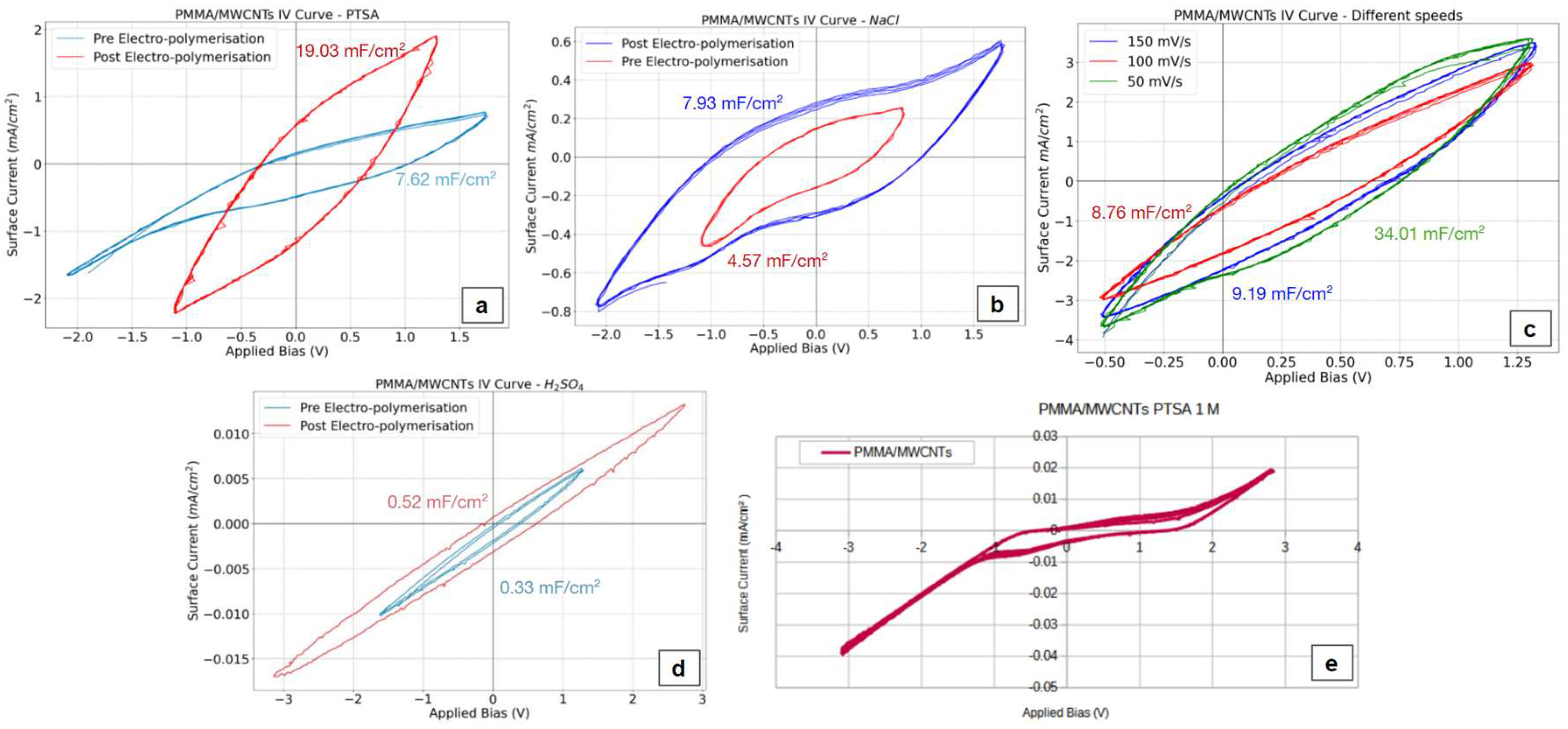
Further investigation using cyclic voltammograms demonstrated that electropolymerization with polyaniline (in a 1 M PTSA aqueous solution) led to an increase in active current, resulting in the area specific capacitance shifting from 7.62 mF/cm2 to 19.03 mF/cm2. The layering of PANI enabled the film to store charge across a wider voltage range, spanning from -2V to 1.7V in 1 M NaCl solution (Figure 6b), albeit at the cost of a lower active current in those conditions (4.57 mF/cm2 to 7.93 mF/cm2 after the electropolymerization). The stability of films (without electropolymerized PANI) was also assessed; subjecting the films to 10 consecutive scans in a 1 M PTSA solution using broad voltage range (from -3 V to + 3 V), resulted in stable diagrams with minimal fluctuations in peak values (Figure 6e). To evaluate the film's suitability for lithium battery applications, measurements were conducted in a 0.5 M H2SO4 solution (Figure 6d), simulating a lithium battery environment. However, the low active current values obtained suggest that these films are not well-suited for lithium or organic batteries. Finally, the influence of scan rate on the films' charge storage capacity was examined (Figure 6c). Increasing the scan rate in a 1 M PTSA solution from 50 to 100 and 150 mV/s resulted in a decrease in cp 34.01 to 8.76 and 9.19 mF/cm2 respectively. This phenomenon is likely attributed to the inherent lag in the materials' response to rapid changes in current direction.
4. Discussion
A novel and straightforward method for the reproducible synthesis of vertically aligned carbon nanotubes using a conventional CVD furnace has been investigated. This method is based on the vaporization of two separate solutions: a catalytic metalorganic solution and a carbon source organic solution., leading to a floating catalyst approach, where they react at 850°C on the substrate. Following the synthesis of the CNT forests, is their isolation from the substrate. To achieve this, a PMMA solution is applied to CNT covered substrate and polymerized under pressure to create a uniform, thin, flexible, and conductive film. Characterization methods demonstrated the production of high- MWCNTs with an ID/IG ratio comparable to that achieved by other thin film deposition techniques such as spray pyrolysis [13] and specialized CVD methods like PECVD, without requiring further purification processes [16,38,39]. The resulting thin films are flexible, conductive, and stable, suitable for additional processes like electropolymerization. A higher ID/IG ratio indicates a higher defect degree with factors like the nanotube's aspect ratio (length-to-diameter ratio) and surface modifications (e.g., crosslinking, functionalization) can contribute to defect formation [40,41]. Lower aspect ratios typically lead to more defects, negatively impacting the MWCNTs' mechanical and electrical properties [42]. Electropolymerization of PANI on PMMA/CNT forests films results in area specific capacitance comparable to recent literature in the field [19,23,24,43]. With this technique, it is possible to produce doped nanotubes that, due to the reduced need for further processing, can maintain their oriented structure and the unique characteristics that this structure imparts [44]. Further study of the growth mechanism of carbon nanotubes with floating catalysts and the morphological and electrical characteristics of the produced membrane is necessary. However, the measurements and characterizations presented constitute encouraging results for the continuation of the method, with the most suitable application being flexible electrodes for sensors [4,45–47].
5. Conclusions
This study employed a simple two-step floating catalyst chemical vapor deposition method to fabricate highly oriented, high-purity carbon nanotube forests for conductive and flexible thin film applications. The decoupled introduction of the catalyst and carbon source in a conventional CVD system minimized impurities, reducing the need for post-treatment processes. SEM revealed vertically aligned CNTs perpendicular to the substrate. TEM analysis confirmed the formation of multi-walled CNTs with an average outer diameter of 18 nm and an inner diameter of 8 nm. The as-synthesized CNT forests exhibited minimal amorphous carbon deposition, with ID/IG ratios ranging from 0.68 to 0.82 depending on the precursor composition. The MWCNT forests exhibited a sheet resistance of 47 Ω/square and a conductivity ranging from 950 to 966 S/m. Incorporation of the CNT forests into a PMMA matrix yielded thin films with a sheet resistance of 10 Ω/square, a resistivity of 90 μΩ.m, and a conductivity ranging from 9.3 to 11 kS/m. The PMMA coating reduced the film thickness to 10 μm. Subsequent electropolymerization of PANI on the PMMA/CNT films increased the area-specific capacitance from 7.62 mF/cm2 to 19.03 mF/cm2, while maintaining stability in an aqueous environment.
Author Contributions
“Conceptualization, F.P., S.S., A-F.T.; methodology, F.P., S.S.; investigation, F.P., S.S.; resources, C.C.; data curation, F.P., S.S.; writing—original draft preparation, F.P., S.S.; writing—review and editing, A-F.T.; visualization, F.P., S.S.; supervision, C.C.; project administration, A-F.T.; funding acquisition, C.C. All authors have read and agreed to the published version of the manuscript.”.
Funding
The APC was funded by the EC Horizon EU SUBBIMATT Project, grant number 101129911.
Data Availability Statement
Dataset available on request from the authors.
Acknowledgements
The current research has been carried out under the framework of FAST-SMART (G.A. 862289) and SUBBIMATT (G.A. 101129911) co-Funded by the European Union. Views and opinions expressed are however those of the author(s) only and do not necessarily reflect those of the European Union or the European Health and Digital Executive Agency (HADEA). Neither the European Union nor the granting authority can be held responsible for them.
Conflicts of Interest
The authors declare no conflicts of interest. “The funders had no role in the design of the study; in the collection, analyses, or interpretation of data; in the writing of the manuscript; or in the decision to publish the results”.
References
- Dai, H. Carbon nanotubes: opportunities and challenges. Surf. Sci. 2001, 500, 218–241. [Google Scholar] [CrossRef]
- Li, Q.; Li, D.; Wang, H.; Wang, H.-G.; Li, Y.; Si, Z.; Duan, Q. Conjugated Carbonyl Polymer-Based Flexible Cathode for Superior Lithium-Organic Batteries. ACS Appl. Mater. Interfaces 2019, 11, 28801–28808. [Google Scholar] [CrossRef]
- Wang, Z.; Bramnik, N.; Roy, S.; Di Benedetto, G.; Zunino, J.L.; Mitra, S. Flexible zinc–carbon batteries with multiwalled carbon nanotube/conductive polymer cathode matrix. J. Power Sources 2013, 237, 210–214. [Google Scholar] [CrossRef]
- Verma, G.; Pandey, V.; Islam, M.; Kumar, M.; Gupta, A. Room temperature operated flexible La-ZnO/MWCNTs sensor for ppb level carbon monoxide detection. J. Micromechanics Microengineering 2023, 33, 095003. [Google Scholar] [CrossRef]
- Shajari, S.; Rajabian, M.; Kamkar, M.; Sudak, L.J.; Sundararaj, U. A solution-processable and highly flexible conductor of a fluoroelastomer FKM and carbon nanotubes with tuned electrical conductivity and mechanical performance. Soft Matter 2022, 18, 7537–7549. [Google Scholar] [CrossRef]
- Gakis, G.P.; Termine, S.; Trompeta, A.-F.A.; Aviziotis, I.G.; Charitidis, C.A. Unraveling the mechanisms of carbon nanotube growth by chemical vapor deposition. Chem. Eng. J. 2022, 445. [Google Scholar] [CrossRef]
- Hou, P.; Zhang, F.; Zhang, L.; Liu, C.; Cheng, H. Synthesis of Carbon Nanotubes by Floating Catalyst Chemical Vapor Deposition and Their Applications. Adv. Funct. Mater. 2022, 32, 2108541. [Google Scholar] [CrossRef]
- Sivamaran, V.; Balasubramanian, V.; Gopalakrishnan, M.; Viswabaskaran, V.; Rao, A.G.; Selvamani, S. Carbon nanotubes, nanorings, and nanospheres: Synthesis and fabrication via chemical vapor deposition—a review. Nanomater. Nanotechnol. 2022, 12. [Google Scholar] [CrossRef]
- Trompeta, A.-F.; Koklioti, M.A.; Perivoliotis, D.K.; Lynch, I.; Charitidis, C.A. Towards a holistic environmental impact assessment of carbon nanotube growth through chemical vapour deposition. J. Clean. Prod. 2016, 129, 384–394. [Google Scholar] [CrossRef]
- Meysami, S.S.; Koós, A.A.; Dillon, F.; Grobert, N. Aerosol-assisted chemical vapour deposition synthesis of multi-wall carbon nanotubes: II. An analytical study. Carbon 2013, 58, 159–169. [Google Scholar] [CrossRef]
- Meysami, S.S.; Dillon, F.; Koós, A.A.; Aslam, Z.; Grobert, N. Aerosol-assisted chemical vapour deposition synthesis of multi-wall carbon nanotubes: I. Mapping the reactor. Carbon 2013, 58, 151–158. [Google Scholar] [CrossRef]
- Meysami, S.S.; Koós, A.A.; Dillon, F.; Dutta, M.; Grobert, N. Aerosol-assisted chemical vapour deposition synthesis of multi-wall carbon nanotubes: III. Towards upscaling. Carbon 2015, 88, 148–156. [Google Scholar] [CrossRef]
- Lara-Romero, J.; Ocampo-Macias, T.; Martínez-Suarez, R.; Rangel-Segura, R.; López-Tinoco, J.; Paraguay-Delgado, F.; Alonso-Nuñez, G.; Jiménez-Sandoval, S.; Chiñas-Castillo, F. Parametric Study of the Synthesis of Carbon Nanotubes by Spray Pyrolysis of a Biorenewable Feedstock: α-Pinene. ACS Sustain. Chem. Eng. 2017, 5, 3890–3896. [Google Scholar] [CrossRef]
- Azhar, N.E.A.; Nurfazianawatie, M.Z.; Yusoff, K.M.; Omar, H.; Rosman, N.F.; Malek, N.S.A.; Akhir, R.M.; Buniyamin, I.; Salifairus, M.J.; Husairi, F.S.; et al. Mechanism of vertically arrays of carbon nanotubes by camphor based catalysed in-situ growth. Full- Nanotub. Carbon Nanostructures 2021, 30, 476–486. [Google Scholar] [CrossRef]
- Hajilounezhad, T.; Bao, R.; Palaniappan, K.; Bunyak, F.; Calyam, P.; Maschmann, M.R. Predicting carbon nanotube forest attributes and mechanical properties using simulated images and deep learning. npj Comput. Mater. 2021, 7, 1–11. [Google Scholar] [CrossRef]
- Kinoshita, T.; Karita, M.; Nakano, T.; Inoue, Y. Two step floating catalyst chemical vapor deposition including in situ fabrication of catalyst nanoparticles and carbon nanotube forest growth with low impurity level. Carbon 2019, 144, 152–160. [Google Scholar] [CrossRef]
- Wulan, P.P.D.K.; Fathony, A.; Ulfa, A.S. Utilization of camphor as an alternative carbon source for the synthesis of carbon nanotubes using floating catalyst. J. Physics: Conf. Ser. 2019, 1349, 012059. [Google Scholar] [CrossRef]
- Zhu, Z.; Garcia-Gancedo, L.; Flewitt, A.J.; Xie, H.; Moussy, F.; Milne, W.I. A Critical Review of Glucose Biosensors Based on Carbon Nanomaterials: Carbon Nanotubes and Graphene. Sensors 2012, 12, 5996–6022. [Google Scholar] [CrossRef]
- Ubnoske, S.M.; Raut, A.S.; Brown, B.; Parker, C.B.; Stoner, B.R.; Glass, J.T. Perspectives on the Growth of High Edge Density Carbon Nanostructures: Transitions from Vertically Oriented Graphene Nanosheets to Graphenated Carbon Nanotubes. J. Phys. Chem. C 2014, 118, 16126–16132. [Google Scholar] [CrossRef]
- Tsuji, T.; Shimizu, Y.; Kim, J.; Sakakita, H.; Hata, K.; Futaba, D.N.; Sakurai, S. A mini-microplasma-based synthesis reactor for growing highly crystalline carbon nanotubes. Carbon 2021, 173, 448–453. [Google Scholar] [CrossRef]
- Kurenya, A.G.; Bulusheva, L.G.; Asanov, I.P.; Sedelnikova, O.V.; Okotrub, A.V. Field emission properties of aligned CNx nanotube arrays synthesized by pyrolysis of a ferrocene/acetonitrile aerosol at different temperatures. Phys. Status solidi (b) 2015, 252, 2524–2529. [Google Scholar] [CrossRef]
- Ranjan, B.; Kaur, D. Pseudocapacitive Storage in Molybdenum Oxynitride Nanostructures Reactively Sputtered on Stainless-Steel Mesh Towards an All-Solid-State Flexible Supercapacitor. Small 2023, 20, e2307723. [Google Scholar] [CrossRef]
- Zhou, Y.; Cao, C.; Cao, Y.; Han, Q.; Parker, C.B.; Glass, J.T. Robust and High-Performance Electrodes via Crumpled Au-CNT Forests for Stretchable Supercapacitors. Matter 2020, 2, 1307–1323. [Google Scholar] [CrossRef]
- Cao, C.; Zhou, Y.; Ubnoske, S.; Zang, J.; Cao, Y.; Henry, P.; Parker, C.B.; Glass, J.T. Highly Stretchable Supercapacitors via Crumpled Vertically Aligned Carbon Nanotube Forests. Adv. Energy Mater. 2019, 9. [Google Scholar] [CrossRef]
- Dresselhaus, M.S.; Dresselhaus, G.; Saito, R.; Jorio, A. Raman spectroscopy of carbon nanotubes. Phys. Rep. 2005, 409, 47–99. [Google Scholar] [CrossRef]
- Telg, H.; Fouquet, M.; Maultzsch, J.; Wu, Y.; Chandra, B.; Hone, J.; Heinz, T.F.; Thomsen, C. G- and G+ in the Raman spectrum of isolated nanotube: a study on resonance conditions and lineshape. Phys. Status solidi (b) 2008, 245, 2189–2192. [Google Scholar] [CrossRef]
- Aoki, A.; Ogasawara, T.; Aoki, T.; Ishida, Y.; Shimamura, Y.; Inoue, Y. Raman spectroscopy used for estimating the effective elastic modulus of carbon nanotubes in aligned multi-walled carbon nanotubes/ epoxy composites under tensile loading. Compos. Part A: Appl. Sci. Manuf. 2023, 167. [Google Scholar] [CrossRef]
- Downes, A.; Elfick, A. Raman Spectroscopy and Related Techniques in Biomedicine. Sensors 2010, 10, 1871–1889. [Google Scholar] [CrossRef] [PubMed]
- Wang, H.; Li, J.; Zhang, X.; Ouyang, Z.; Li, Q.; Su, Z.; Wei, G. Synthesis, characterization and drug release application of carbon nanotube-polymer nanosphere composites. RSC Adv. 2013, 3, 9304–9310. [Google Scholar] [CrossRef]
- Electrical Measurement, Signal Processing, and Displays; Taylor & Francis: London, United Kingdom, 2003.
- Kumari, R.; Tyagi, P.K.; Puri, N.K. Work function and electrical properties of individual multiwalled carbon nanotube: influenced by nature of catalyst and substrate. Appl. Phys. A 2018, 124, 466. [Google Scholar] [CrossRef]
- Lau, C.H.; Cervini, R.; Clarke, S.R.; Markovic, M.G.; Matisons, J.G.; Hawkins, S.C.; Huynh, C.P.; Simon, G.P. The effect of functionalization on structure and electrical conductivity of multi-walled carbon nanotubes. J. Nanoparticle Res. 2008, 10, 77–88. [Google Scholar] [CrossRef]
- Thomas, K.J.; Sheeba, M.; Nampoori, V.P.N.; Vallabhan, C.P.G.; Radhakrishnan, P. Raman spectra of polymethyl methacrylate optical fibres excited by a 532 nm diode pumped solid state laser. J. Opt. A: Pure Appl. Opt. 2008, 10. [Google Scholar] [CrossRef]
- Hasoon, S.; Salah Abdullah, H. Electrochemical Polymerization and Raman Study of Polypyrrole and Polyaniline Thin Films. Article in Interna-tional Journal of the Physical Sciences 2012, 7 (38), 5468–5476. [CrossRef]
- Mergen, B.; Arda, E.; Evingür, G.A. Electrical, mechanical, and optical changes in MWCNT-doped PMMA composite films. J. Compos. Mater. 2020, 54, 2449–2459. [Google Scholar] [CrossRef]
- Jiang, K.; Gerhardt, R.A. Fabrication and Supercapacitor Applications of Multiwall Carbon Nanotube Thin Films. C 2021, 7, 70. [Google Scholar] [CrossRef]
- Yuan, H.; Xiong, Y.; Luo, G.; Li, M.; Shen, Q.; Zhang, L. Microstructure and electrical conductivity of CNTs/PMMA nanocomposite foams foaming by supercritical carbon dioxide. J. Wuhan Univ. Technol. Sci. Ed. 2016, 31, 481–486. [Google Scholar] [CrossRef]
- Komatsubara, K.; Suzuki, H.; Inoue, H.; Kishibuchi, M.; Takahashi, S.; Marui, T.; Umezawa, S.; Nakagawa, T.; Nasu, K.; Maetani, M.; et al. Highly Oriented Carbon Nanotube Supercapacitors. ACS Appl. Nano Mater. 2022, 5, 1521–1532. [Google Scholar] [CrossRef]
- Brachetti-Sibaja, S.B.; Palma-Ramírez, D.; Torres-Huerta, A.M.; Domínguez-Crespo, M.A.; Dorantes-Rosales, H.J.; Rodríguez-Salazar, A.E.; Ramírez-Meneses, E. CVD Conditions for MWCNTs Production and Their Effects on the Optical and Electrical Properties of PPy/MWCNTs, PANI/MWCNTs Nanocomposites by In Situ Electropolymerization. Polymers 2021, 13, 351. [Google Scholar] [CrossRef] [PubMed]
- Guest, J.; Kinloch, I.A.; Young, R.J. The role of filler aspect ratio in the reinforcement of an epoxy resin with graphene nanoplatelets. J. Mater. Sci. 2023, 58, 9473–9485. [Google Scholar] [CrossRef]
- Konsta-Gdoutos, M.S.; Danoglidis, P.A.; Shah, S.P. High modulus concrete: Effects of low carbon nanotube and nanofiber additions. Theor. Appl. Fract. Mech. 2019, 103, 102295. [Google Scholar] [CrossRef]
- Inoue, H.; Hada, M.; Nakagawa, T.; Marui, T.; Nishikawa, T.; Yamashita, Y.; Inoue, Y.; Takahashi, K.; Hayashi, Y. The critical role of the forest morphology for dry drawability of few-walled carbon nanotubes. Carbon 2020, 158, 662–671. [Google Scholar] [CrossRef]
- Wu, Z.; Zhang, X.; Jin, X.; Li, T.; Ge, J.; Li, Z. A Review on Cutting Edge Technologies of Silicon-Based Supercapacitors. J. Nanomater. 2021, 2021, 1–17. [Google Scholar] [CrossRef]
- Leu, Y.-A.; Yeh, M.-H.; Lin, L.-Y.; Li, T.-J.; Chang, L.-Y.; Shen, S.-Y.; Li, Y.-S.; Chen, G.-L.; Chiang, W.-H.; Lin, J.-J.; et al. Thermally Stable Boron-Doped Multiwalled Carbon Nanotubes as a Pt-free Counter Electrode for Dye-Sensitized Solar Cells. ACS Sustain. Chem. Eng. 2017, 5, 537–546. [Google Scholar] [CrossRef]
- Phonklam, K.; Wannapob, R.; Sriwimol, W.; Thavarungkul, P.; Phairatana, T. A novel molecularly imprinted polymer PMB/MWCNTs sensor for highly-sensitive cardiac troponin T detection. Sensors Actuators B: Chem. 2020, 308, 127630. [Google Scholar] [CrossRef]
- Beitollahi, H.; Movahedifar, F.; Tajik, S.; Jahani, S. A Review on the Effects of Introducing CNTs in the Modification Process of Electrochemical Sensors. Electroanalysis 2019, 31, 1195–1203. [Google Scholar] [CrossRef]
- Nag-Chowdhury, S.; Bellegou, H.; Pillin, I.; Castro, M.; Longrais, P.; Feller, J. Non-intrusive health monitoring of infused composites with embedded carbon quantum piezo-resistive sensors. Compos. Sci. Technol. 2016, 123, 286–294. [Google Scholar] [CrossRef]
Figure 1.
Schematic depiction of CNT forest production utilizing two solutions within a CVD reactor. Images (a) through (d) display the sequential bending of the same film at room temperature.
Figure 1.
Schematic depiction of CNT forest production utilizing two solutions within a CVD reactor. Images (a) through (d) display the sequential bending of the same film at room temperature.
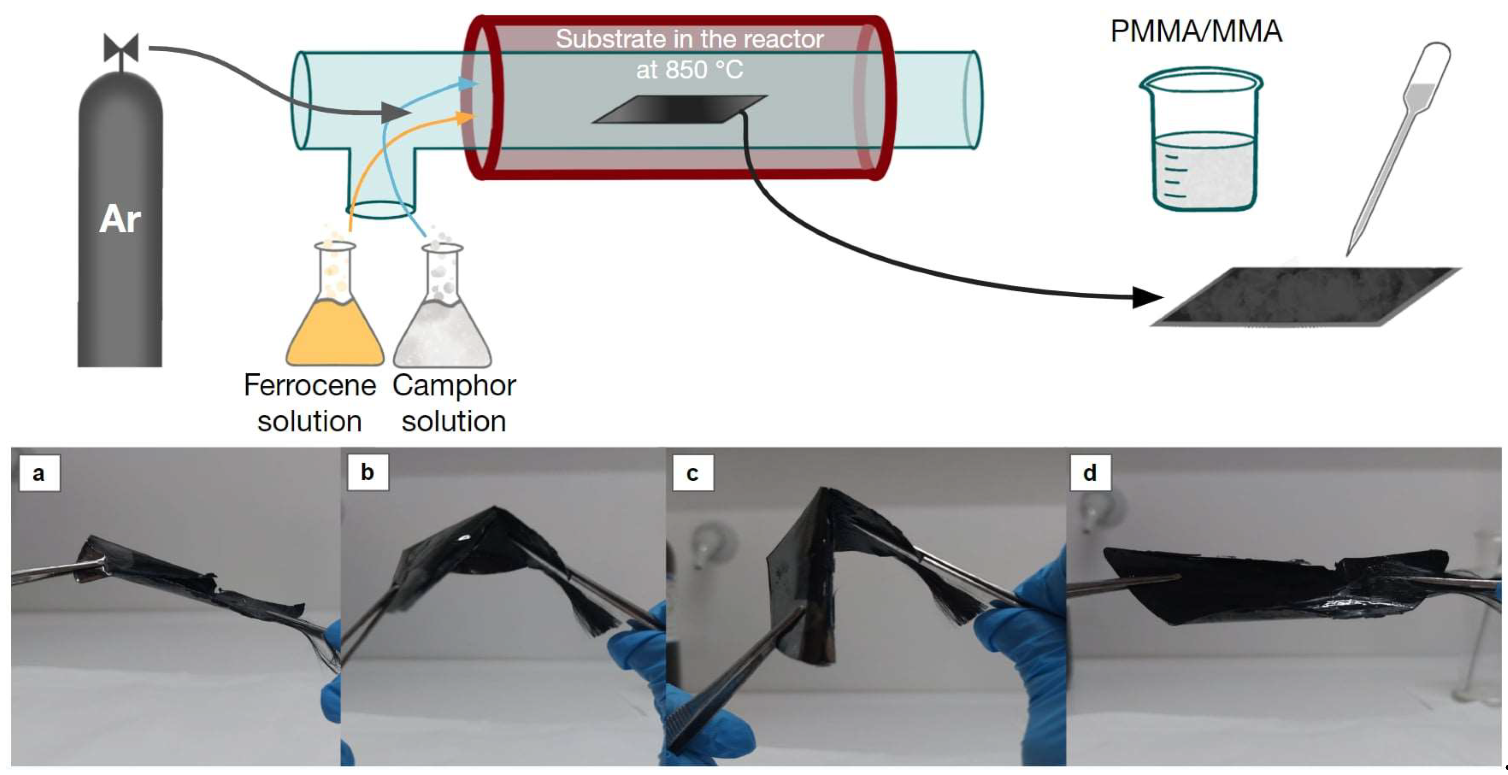
Figure 2.
SEM image of CNT forests on the substrate showing the cross-section (a) and TEM.
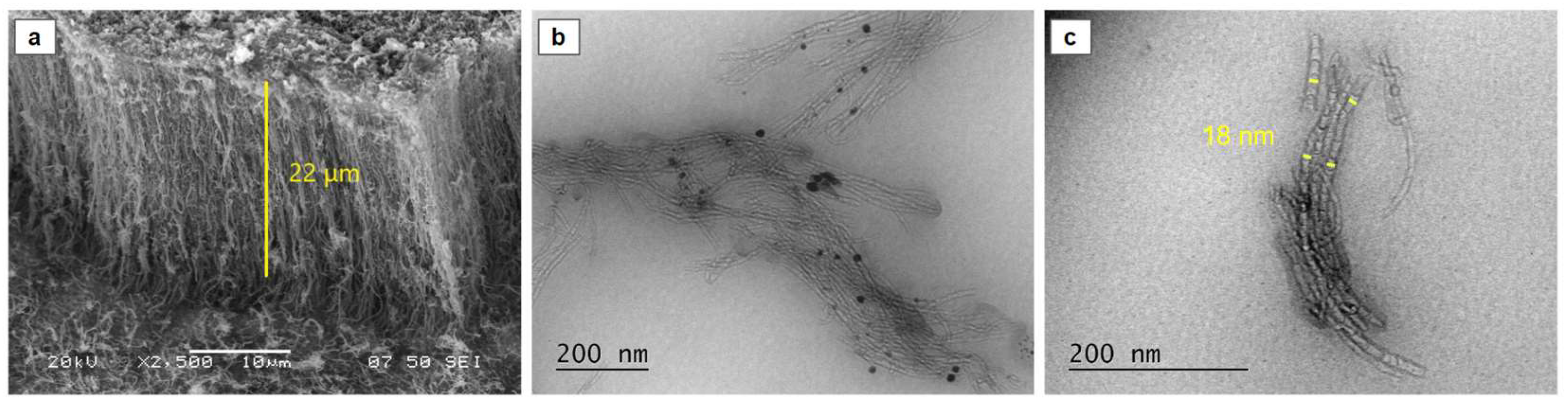
Figure 3.
Raman spectra of CNT forests on the substrate (a), produced with various combinations of S1 and S2 as shown in the ID/IG ratio is stated on the bottom with colors corresponding to those of the Raman spectra (b). TGA for MWCNTs fabricated with different configurations of S1 and S2 (c).
Figure 3.
Raman spectra of CNT forests on the substrate (a), produced with various combinations of S1 and S2 as shown in the ID/IG ratio is stated on the bottom with colors corresponding to those of the Raman spectra (b). TGA for MWCNTs fabricated with different configurations of S1 and S2 (c).
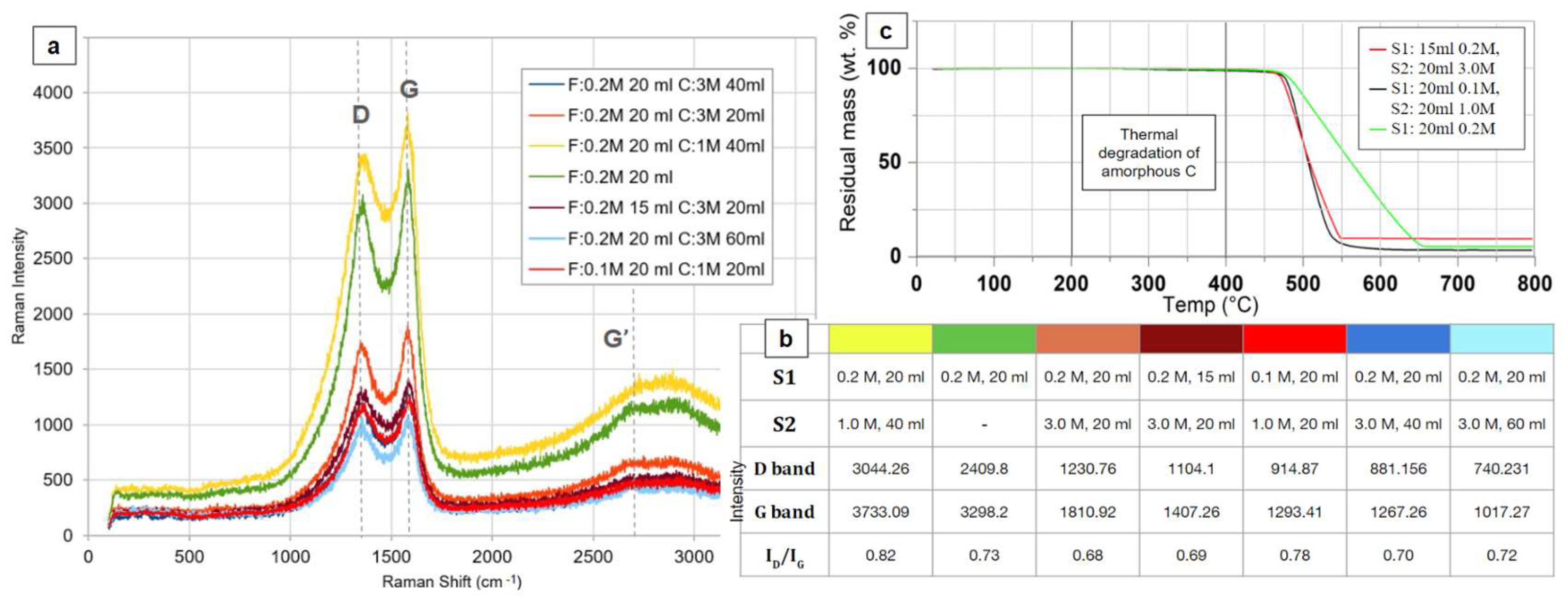
Figure 4.
SEM image of the produced free-standing CNT forest thin film.
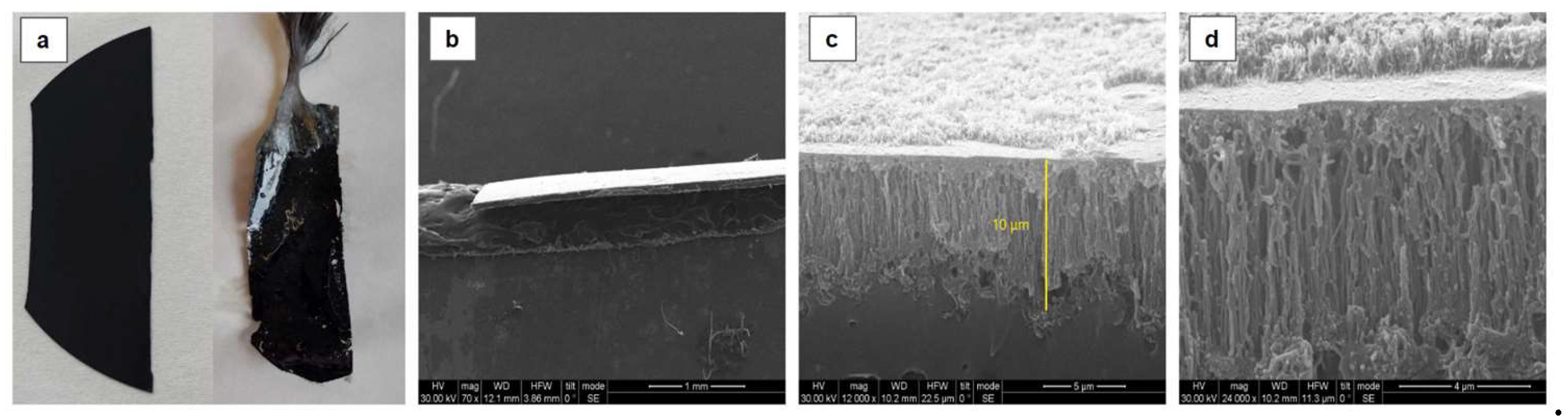
Figure 5.
(a) Raman spectra of MWCNT/PMMA thin film presenting mainly the characteristic peaks of PMMA, (b) comparative diagram of Raman peaks of CNT forests on the substrate (orange) and PANI/PMMA/CNT forest film (blue).
Figure 5.
(a) Raman spectra of MWCNT/PMMA thin film presenting mainly the characteristic peaks of PMMA, (b) comparative diagram of Raman peaks of CNT forests on the substrate (orange) and PANI/PMMA/CNT forest film (blue).
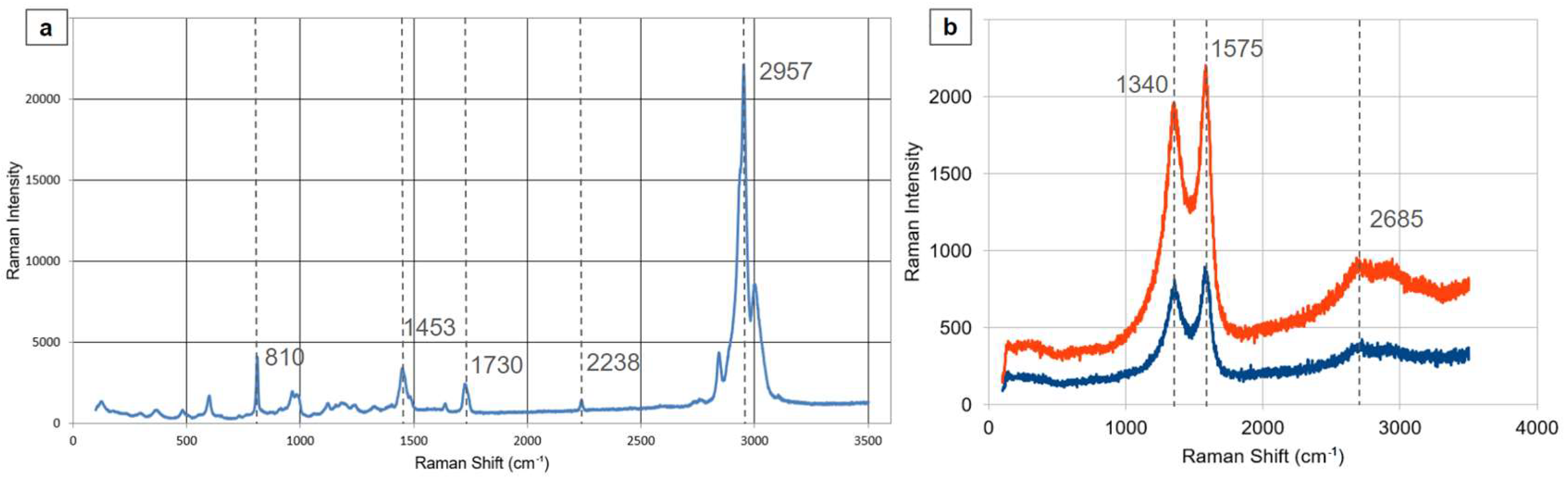
Figure 6.
Cyclic voltamograms on MWCNT/PMMA thin films under different conditions. The area specific capacitance inceases after the electropolymerization of PANI in different solutions (a,b,d), is inversely proportional to the scan rate (c) and remains the same after 10 consecutive cycles (e) in the PTSA solution.
Disclaimer/Publisher’s Note: The statements, opinions and data contained in all publications are solely those of the individual author(s) and contributor(s) and not of MDPI and/or the editor(s). MDPI and/or the editor(s) disclaim responsibility for any injury to people or property resulting from any ideas, methods, instructions or products referred to in the content. |
© 2024 by the authors. Licensee MDPI, Basel, Switzerland. This article is an open access article distributed under the terms and conditions of the Creative Commons Attribution (CC BY) license (http://creativecommons.org/licenses/by/4.0/).
Copyright: This open access article is published under a Creative Commons CC BY 4.0 license, which permit the free download, distribution, and reuse, provided that the author and preprint are cited in any reuse.


