
Submitted:
17 October 2024
Posted:
21 October 2024
You are already at the latest version
Abstract
Functional graded materials (FGMs) have been successfully applied in improving the insulation performance of insulators, yet there is currently no relevant literature on their application in dry-type transformers. Therefore, it is meaningful to study on the feasibility of using FGMs to improve the insulation performance of dry-type transformers through research on electric field distribution. This paper sets FGMs in the dry-type transformer spacer only or both spacer and winding end to change the relative permittivity values in the corresponding areas. By comparing the electric field distribution characteristics on the inner and outer surfaces of the high-voltage coil and the lower surface of the spacer of the dry-type transformer under each control method with the case without setting FGMs, the study found that when FGMs were only set on the spacer, the control methods set in this paper could not improve the electric field distribution of the transformer. When FGMs are employed at the spacers and end windings, two modulation strategies can mitigate the electric field intensity on the outer surface of high-voltage windings. Specifically, a continuous increase in relative permittivity can reduce the electric field intensity by 34.02%, while an initial decrease followed by an increase can result in a reduction of 13.58%. This paper provides theoretical guidance for insulation design of transformers with high voltage levels of 66 kV and above, especially as transformers with high voltage levels face greater challenges in regulating surface electric fields.
Keywords:
dry-type transformer
; functional graded material
; finite element method
; electric field calculation
1. Introduction
Transformers, as crucial components in power systems, have seen a surge in demand with the rapid economic development [1,2,3]. Dry-type transformers, known for their strong short-circuit resistance, high safety, simple maintenance, high operational efficiency, and compact size, are widely applied and hold significant prospects for future applications [4,5,6]. Should insulating faults occur in dry-type transformers, they can pose severe threats to critical loads and the entire power system, leading to substantial economic losses. Therefore, enhancing the insulating performance of dry-type transformers is of paramount importance [7,8].
Numerous scholars have analyzed the distribution of electric field strength in dry-type transformers, either as a whole or in specific structures, drawing conclusions that are highly significant for the insulation design of these transformers [9,10,11,12]. There are also studies on the application of functional graded materials (FGMs) in various insulating devices, such as insulators, to improve electric field distribution characteristics and elevate insulation levels. Dong conducted research on the use of FGMs to regulate the electric field distribution around three-column insulators in high-voltage direct current gas-insulated transmission lines [13]. Zhang verified the applicability of FGMs in enhancing the insulation performance of electric cable joints [14]. Bian proposed that the use of FGM technology in the preparation of insulating partitions in high-voltage switchgear can effectively reduce the maximum electric field strength on the surface [15].
However, there are no relevant papers on the treatment of functional graded materials in the field of dry-type transformers, and its feasibility still needs to be demonstrated. Currently, it is still in the stage of theoretical exploration.
This paper aims to identify the points of high electric field strength within dry-type transformers, which are the weak points in insulation, by analyzing the characteristics of electric field distribution. Building upon this, the paper incorporates FGMs, utilizing this material processing technology that controls material composition and structure to form a gradual variation in composition or structure within the material. This can alter the dielectric properties of the material, thereby affecting the distribution of the electric field [16,17,18]. Applying this technology to dry-type transformers can offer certain benefits to their insulation theoretically. Firstly, FGM treatment can reduce the concentration of the electric field, allowing for a more uniform electric field distribution within the material and reducing the risk of partial discharge. Secondly, an optimized electric field distribution aids in enhancing the insulation performance of dry-type transformers.
Therefore, this paper introduces functional graded materials into a 66kV epoxy resin cast dry-type transformer. The COMSOL software is employed to construct a model of the dry-type transformer to investigate the impact of functional graded materials on the electric field distribution within the transformer, thereby providing a reference for transformer design. Firstly, combining the basic theory of electrostatic field and finite element calculation method, a 66kV epoxy resin cast dry-type transformer model was established using the finite element software COMSOL, and the electric field was calculated to study its distribution, with a focus on analyzing the electric field distribution of the high-voltage winding. Subsequently, functional graded materials are set under two scenarios: with spacers only and with both spacers and end windings. By altering the relative permittivity, the electric field distribution under different conditions is obtained. Finally, the relative permittivity is set to increase sequentially, decrease sequentially, and fluctuate, and the resulting electric field distribution characteristics are compared and analyzed with the case where no functional graded materials are used. This comparison offers valuable insights for the insulation design of epoxy-encapsulated dry-type transformers.
2. Model Establishment and Functional Graded Material Setting
2.1. Establishment of Transformer Model
To simplify the study, the following assumptions are made regarding the dry-type transformer model in this paper:
- The influence of wire arrangement on the end electric field of the dry-type transformer, the inter-turn insulation of the transformer windings, and the insulating sleeves in the main air duct are neglected;
- The yoke is equivalent to an infinitely large flat plate perpendicular to the core;
- The voltage applied to the conductors of the transformer winding is assumed to be constant;
- The model is established only for the upper yoke and spacers.
2.2. Electrode and Boundary Condition Settings
In the model, the ground portion represents a potential of zero. Since the core and yoke of the transformer are grounded, the potentials on the surfaces of the core and yoke are also zero.
In the three phases of the dry-type transformer, the voltages are symmetrical; therefore, the potentials of the high-voltage windings relative to the yoke must also be equal.
As depicted in Figure 2, the high-voltage windings of the transformer are connected in a delta configuration. Only when the potential of the yoke is at the geometric center of the three-phase voltages (i.e., point O), do the three-phase high-voltage windings of the dry-type transformer have equal potentials relative to the yoke. The research presented in this paper pertains to a 66kV dry-type transformer, and through calculation, it can be deduced that
However, in practice, the yoke of the dry-type transformer is divided into upper and lower sections. Taking phase A as an example, the upper end is point A, with a potential of relative to the upper yoke; the lower end is point B, with a potential of relative to the lower yoke. The potential difference between the upper and lower ends is 66 kV, which is equal to the phase voltage of the transformer. For the winding voltage between the two ends, one can refer to point D in the diagram; the winding at position D should have a voltage set to .
To precisely set the voltage on each section of the winding is quite complex. Since the main focus of this chapter is the electric field at the ends of the dry-type transformer, it is sufficient to ensure that the voltage values of the coils near the ends are essentially accurate. In the electrode setting section of this chapter, the following simplifications were adopted:
- 5.
- The voltage of the coil closest to the upper end among the entire high-voltage windings is set to , and the voltage for the remaining coils is set according to the number of turns in the coils;
- 6.
- The low-voltage winding of the transformer is not processed, and the conductor voltage is still set to 1.14 kV.
2.3. Functional Graded Material Setting
In the construction of dry-type transformers, the insulating performance at the high-voltage winding terminal is particularly critical and also the most susceptible to damage. As one of the core components of dry-type transformers, the importance of the spacer block is self-evident. Therefore, this paper first considers the application of functional graded materials (FGMs) on the spacer, a method that is highly feasible and cost-effective.
In this study, two approaches will be employed to incorporate FGM into a 66kV epoxy-encapsulated dry-type transformer: one where FGM is applied only to the spacers, and another where FGM is applied to both the spacers and the winding end turns. The relative permittivity will be set to increase sequentially, decrease sequentially, and fluctuate in three distinct scenarios. The electric field distribution characteristics on the inner and outer surfaces of the high-voltage windings and the bottom surface of the spacers under these three conditions will be investigated.
2.3.1. Setting of Functional Graded Materials for Spacers
The spacers are uniformly divided into 20 regions to serve as the functional graded material areas, as depicted in Figure 3(a). Calculations are conducted after setting the relative permittivity for each region. The specific modulation methods for the relative permittivity that increases sequentially (hereinafter referred to as Case 1), decreases sequentially (hereinafter referred to as Case 2), and first increases then decreases (hereinafter referred to as Case 3) are illustrated in Figure 3(b). (Note: The order of regions 1-20 is arranged downwards from the top of the spacer.)
2.3.2. Setting of Functional Graded Materials for both Spacers and Winding Ends
In this study, the spacers and the end turns of the windings are uniformly divided into 20 regions each, totaling 40 regions, as illustrated in Figure 4(a). The relative permittivity is modulated in three distinct ways: incrementally increasing (hereinafter referred to as Method 1), incrementally decreasing (hereinafter referred to as Method 2), and decreasing then increasing (hereinafter referred to as Method 3). The electric field distribution characteristics on the inner and outer surfaces of the high-voltage windings and the bottom surface of the spacers under these three conditions are investigated. For Methods 1 and 2, the regions are grouped in pairs, and the relative permittivity is set for each group before calculations are performed. Method 3 groups the both end regions together, for example, region 1 and region 40 are grouped together, and the relative permittivity values are set progressively towards the central regions. The specific modulation methods are depicted in Figure 4(b). (Note: The order of regions 1-40 is arranged from the top of the spacer downwards, with 1-20 being the spacer region and 21-40 being the winding end region.)
3. Results and Analysis of the Influence of Different Functional Graded Material Settings on the Electric Field of Transformers
3.1. Distribution of Transformer Electric Field Without Setting Functional Graded Materials
In order to contrast with the scenario involving the implementation of functional graded materials, this paper first constructs a dry-type transformer model using COMSOL software. Subsequently, calculations are directly performed within the software to obtain the computational results in the absence of functionally graded materials. The resulting electric field cloud diagram is depicted in Figure 5. (The cloud and contour plots depicted in the figure represent the magnitude of the electric field strength, with the parameter name in COMSOL being es.normE, and the unit is kV/cm. All subsequent electric field cloud diagrams adhere to this convention.)
It can be observed from the figure that, in the absence of a functionally graded material, the maximum value of the electric field in a 66kV dry-type transformer is distributed within the high-voltage winding, and is located near the upper surface of the first winding section, with a maximum electric field strength reaching 5.623 kV/cm. By extracting the data from the simulation calculations, the maximum and average electric field intensities at each position can be determined. It is found that the maximum value on the inner surface of the high-voltage winding can reach 3.043 kV/cm, with an average value of 0.774 kV/cm; the maximum value on the outer surface of the high-voltage winding can reach 2.584 kV/cm, with an average value of 0.328 kV/cm. Furthermore, the maximum electric field intensity at the lower surface of the spacer block is 2.629 kV/cm, with an average value of 1.072 kV/cm.
3.2. Distribution of Transformer Electric Field when only Setting Functional Graded Materials for Spacers
Following the control methods mentioned in Section 2.3.1 for Cases 1, 2, and 3, functional graded materials are configured and calculations are performed to obtain the electric field distribution diagrams on the inner and outer surfaces of the high-voltage winding and the lower surface of the spacer block under different conditions. These results are compared with the situation where no functionally graded materials are applied to analyze the impact of FGMs on the electric field distribution under various conditions. The electric field cloud diagrams are shown in Figure 6.
Similarly, data extracted from the simulation calculations are used to compute the maximum and average electric field intensities on the inner and outer surfaces of the high-voltage winding and the lower surface of the spacer block under Cases 1, 2, and 3. These values are then compared with the corresponding maximum and average electric field intensities when no functionally graded materials are applied, as shown in Table 2. (Note: A "+" sign in the table indicates an increase, while a "-" sign indicates a decrease.)
From the above table, it can be observed that after setting functional graded materials on the spacers of dry-type transformers, the maximum electric field strength on the inner and outer surfaces of the high-voltage coil of the transformer increases compared to the absence of graded materials, which is detrimental to the insulation performance of dry-type transformers. Therefore, it is considered necessary to install functional graded materials in other components.
3.3. Distribution of Transformer Electric Field when Setting Functional Graded Materials for both Spacers and End Windings
Following the investigation in the previous section, it was discovered that the application of functional graded materials (FGMs) solely on the spacer blocks of a dry-type transformer results in an increase in the maximum electric field intensity on the surface of the high-voltage windings, which does not positively influence the insulation performance of the dry-type transformer. In this section, FGMs will be selected for application at both the spacer blocks and the ends of the windings. The FGMs will be configured in three different ways: with relative permittivity increasing sequentially, decreasing sequentially, and first decreasing then increasing. The electric field distribution on the inner and outer surfaces of the high-voltage windings and the lower surface of the spacer blocks will be calculated for each method and compared with the situation without FGMs. Ultimately, the influence of setting FGMs at the spacer blocks and the ends of the windings on the electric field distribution characteristics will be determined.
According to the methods of control mentioned in Section 2.3.2 as Methods 1, 2, and 3, FGMs were configured and calculations were performed to obtain the electric field distribution diagrams for the inner and outer surfaces of the high-voltage windings and the lower surface of the spacer blocks under these conditions. The electric field cloud diagrams are depicted in Figure 7.
Similarly, data extracted from the simulation calculations are used to compute the maximum and average electric field intensities on the inner and outer surfaces of the high-voltage winding and the lower surface of the spacer block under Methods 1, 2, and 3. These values are then compared with the corresponding maximum and average electric field intensities when no functionally graded materials are applied, as shown in Table 3. (Note: A "+" sign in the table indicates an increase, while a "-" sign indicates a decrease.)
From the above table, it can be observed that when functional graded materials are installed on the spacers and winding ends of dry-type transformers, the maximum electric field strength on the outer surface of the high-voltage coil of dry-type transformers decreases under the control of Methods 1 and 3.
It indicates that functional graded materials can be installed on the spacers and winding ends of dry-type transformers, and corresponding control methods can be used to improve the electric field distribution on the outer surface of the high-voltage coil of dry-type transformers and enhance the corresponding insulation performance.
4. Conclusions
The research presented in this paper utilizes the finite element method (FEM) for electrostatic field calculations to study the electric field distribution characteristics of a 66kV epoxy resin-encapsulated dry-type transformer. The transformer model was established in the COMSOL software, and simulations were conducted to analyze the electric field distribution.
In addition to the base model, functional graded materials (FGMs) were applied to two different areas of the dry-type transformer: (1) spacer blocks only, and (2) both spacer blocks and winding ends. Three distinct control methods were employed for the distribution of the relative permittivity within the FGMs. The electric field distribution on the inner and outer surfaces of the high-voltage windings and the lower surface of the spacer blocks was calculated for each configuration and compared to the scenario without FGMs. The main findings are as follows:
- Application of FGMs to Spacer Blocks only: Setting functional graded materials only on the spacer blocks will increase the electric field strength on the inner and outer surfaces of the transformer high-voltage coil, regardless of the control method used. When the relative dielectric constant increases from top to bottom, the electric field strength on the inner surface of the transformer high-voltage coil increases by 16.07%, the electric field strength on the outer surface increases by 20.05%, and the electric field strength on the lower surface of the spacer decreases by 27.16%; When the relative dielectric constant decreases from top to bottom, the electric field strength on the inner and outer surfaces of the high-voltage coil and the lower surface of the pad increases by 22.41%, 0.81%, and 41.69%, respectively; When the relative dielectric constant first increases and then decreases, the electric field strength increases by 27.64%, 7.28%, and 47.74%, respectively;
- Application of FGMs to Spacer Blocks and Winding Ends: As the relative dielectric constant increases from top to bottom, the electric field strength on the inner surface of the transformer high-voltage coil and the lower surface of the spacer increases by 29.08% and 49.41% respectively, while the electric field strength on the outer surface decreases by 34.02%; When the relative dielectric constant decreases from top to bottom, the electric field strength on the inner and outer surfaces of the high-voltage coil and the lower surface of the spacer increases by 81.56%, 101.43%, and 8.98%, respectively; When the relative dielectric constant decreases from both ends to the middle, the electric field strength on the inner surface of the high-voltage coil and the lower surface of the spacer increases by 34.01% and 53.33%, respectively, while the electric field strength on the outer surface decreases by 13.58%. In general, only when the relative dielectric constant gradually increases and first decreases and then increases, will the electric field strength on the outer surface of the high-voltage coil decrease.
This paper demonstrates the feasibility of using functionally graded materials to improve the electric field distribution and enhance the insulation performance of dry-type transformers. Although the methods proposed in this paper effectively reduced the electric field intensity on the outer surface of the high-voltage windings, they increased the electric field intensity at other locations, such as the inner surface of the high-voltage windings and the lower surface of the spacer blocks. Therefore, future research should focus on applying FGMs locally to areas with increased electric fields to achieve an overall reduction in surface electric field intensity.
Author Contributions
Conceptualization, X.Q. and D.Z.; methodology, X.Q., Z.Z. and J.Z.; software, X.Q. Z.Z. and X.D.; validation, X.Q., Y.W. and W.Z.; formal analysis, Z.Z., Y.Z. and L.Y.; investigation, Y.Z. and L.Y.; resources, X.Q.; data curation, Z.Z.; writing—original draft preparation, X.Q and X.D.; writing—review and editing, Z.Z.; supervision, X.Q. and D.Z.; project administration, X.Q. and J.Z; funding acquisition, X.Q. All authors have read and agreed to the published version of the manuscript.
Funding
This research was funded by Jiangsu University's "Blue Project" Funding and the Fundamental Research Funds for the Central Universities, grant number 2023QN1006.
Data Availability Statement
The original contributions presented in the study are included in the article, further inquiries can be directed to the corresponding author.
Acknowledgments
The authors would like to express their gratitude to China University of Mining and Technology for their assistance with this research.
Conflicts of Interest
Author Xinxi Di was employed by Xuzhou Sanxin Power Supply Service Co., Ltd. The authors declare no conflicts of interest. The funders had no role in the design of the study; in the collection, analyses, or interpretation of data; in the writing of the manuscript; or in the decision to publish the results.
References
- Liu, Q.; Mei, N.; Wang, Z.; Sun, J.; Zhou, S. Enhanced Transformer Overcurrent Protection via Oil Temperature Acceleration. Energies 2024, 17, 4916. [Google Scholar] [CrossRef]
- Y. Jia, S. Ji, Z. Bu, X. Yang, S. Li and L. Zhu, "An Insulation Monitoring Method for Transformer Windings Based on Electroluminescence Effect. IEEE Transactions on Dielectrics and Electrical Insulation 2023, 30, 1294–1301. [CrossRef]
- G. Lu, D. Zheng, Q. Zhang and P. Zhang, "Effects of Converter Harmonic Voltages on Transformer Insulation Ageing and an Online Monitoring Method for Interlayer Insulation. IEEE Transactions on Power Electronics 2022, 37, 3504–3514. [CrossRef]
- M. J. Jaafar, N. A. Muhamad, M. K. M. Jamil and N. Rosle, "Electric Field and Potential Changes Studies on Cast-Resin Dry-Type Power Transformer Having Misalignment," 2021 IEEE International Conference on the Properties and Applications of Dielectric Materials (ICPADM), Johor Bahru, Malaysia, 2021, pp. 37-40. [CrossRef]
- V. E. González, P. Gómez and F. P. Espino-Cortés, "Design of the insulating supports in medium voltage dry-type transformers," 2011 Electrical Insulation Conference (EIC)., Annapolis, MD, USA, 2011, pp. 45-48. [CrossRef]
- M. Erdogan and M. K. Eker, "A Comparative Analysis of Partial Discharge in 13 Combined Insulation Structures of 11 Materials Used in Cast-Resin Dry-Type Transformers," in IEEE Transactions on Dielectrics and Electrical Insulation 2022, 29, 2330–2339. [CrossRef]
- Z. Guo et al., "A Novel High Insulation 100 kW Medium Frequency Transformer. IEEE Transactions on Power Electronics 2023, 38, 112–117. [CrossRef]
- X. Zhang et al., "Partial Discharge Measurement and Analysis of Transformer Under Oscillating Lightning Impulse Voltage. IEEE Transactions on Dielectrics and Electrical Insulation 2022, 29, 2303–2311. [CrossRef]
- E. Lesniewska, "The use of 3-D electric field analysis and the analytical approach for improvement of a combined instrument transformer insulation system. IEEE Transactions on Magnetics 2002, 38, 1233–1236. [CrossRef]
- Erick González, Pablo Gómez, Fermín P. Espino-Cortés. Analysis of the electric field distribution on insulating supports of dry-type transformers under high temperature. IET Electric Power Applications 2013, 7, 331–337. [CrossRef]
- S. Saberi, M. Bigdeli and D. Azizian, "Insulation System optimization in Dry-Type Transformer Using Finite Element Method," 2022 30th International Conference on Electrical Engineering (ICEE), Tehran, Iran, Islamic Republic of, 2022, pp. 518-523. [CrossRef]
- Jin Hong, Lin Heyun and Xu Zihong, "Three-dimensional finite element analysis of electric fields at winding ends of dry-type transformer," 2005 International Conference on Electrical Machines and Systems, Nanjing, 2005, pp. 2136-2139 Vol. 3. [CrossRef]
- J. Dong, B. Du, H. Liang and H. Yao, "Parameter Design of Functionally Graded Materials for Tri-Post Insulator in HVDC GIL Under Stationary and Transient Conditions. IEEE Transactions on Dielectrics and Electrical Insulation 2023, 30, 752–760. [CrossRef]
- Y. Zhang et al., "Optimal Design of Functionally Graded Power Cable Joint Utilizing Silicone Rubber/Carbon Nanotube Composites. IEEE Access 2021, 9, 123689–123703. [CrossRef]
- B. Qiuye and S. Desheng, "Analysis of Electric Field Control Characteristics of Dielectric Gradient Insulated Partition Applied to High Voltage Switchgear," 2024 9th Asia Conference on Power and Electrical Engineering (ACPEE), Shanghai, China, 2024, pp. 1148-1154. [CrossRef]
- S. Yanze, D. Qijun, X. Jun, R. Huijuan, L. Guishu and X. Qing, "Plasma Etching Constructs Step Gradient Surface Conductivity to Improve the Insulation Properties of Epoxy Resin. IEEE Transactions on Dielectrics and Electrical Insulation 2024, 31, 2603–2612. [CrossRef]
- J. Dong, H. Liang, B. Du and H. Yao, "Fabrication of Multidimensional Functionally Graded Insulator for HVDC GIS," 2023 IEEE 4th International Conference on Electrical Materials and Power Equipment (ICEMPE), Shanghai, China, 2023, pp. 1-4. [CrossRef]
- H. Yao, B. Du, H. Liang and J. Dong, "DC/AC Electric Field Relaxation With Multidimensional Functionally Graded Materials (ε/-σ-MFGM) for Offshore Bipolar HVDC GIS Spacer. IEEE Transactions on Dielectrics and Electrical Insulation 2023, 30, 2059–2066. [CrossRef]
Figure 1.
The model of transformer.
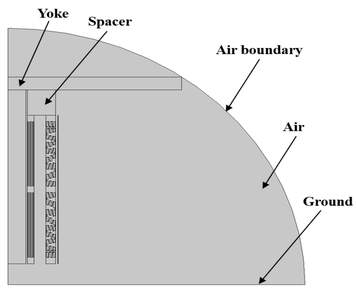
Figure 2.
Voltage vector diagram.
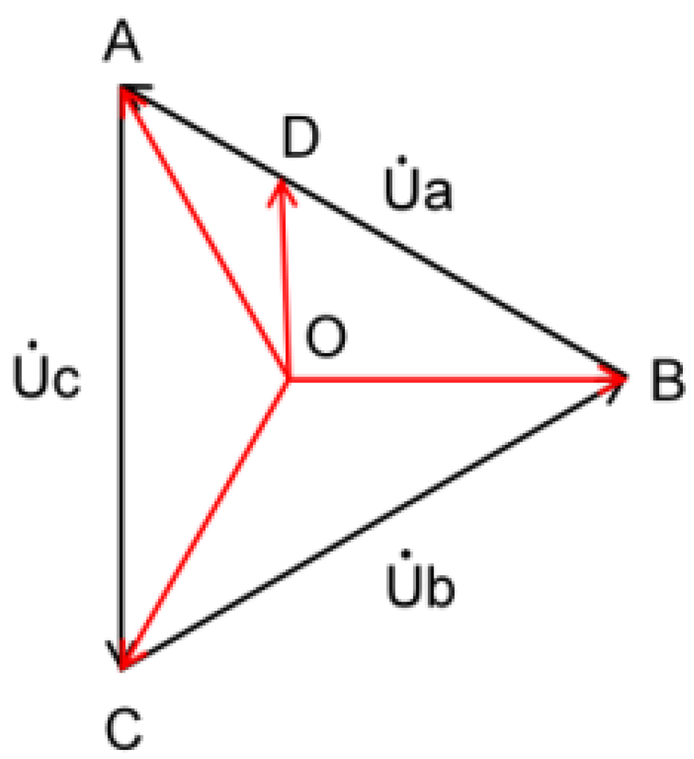
Figure 3.
Setting of functional graded materials for spacers: (a) Functional graded material setting diagram; (b) Functional graded material regulation method.
Figure 3.
Setting of functional graded materials for spacers: (a) Functional graded material setting diagram; (b) Functional graded material regulation method.
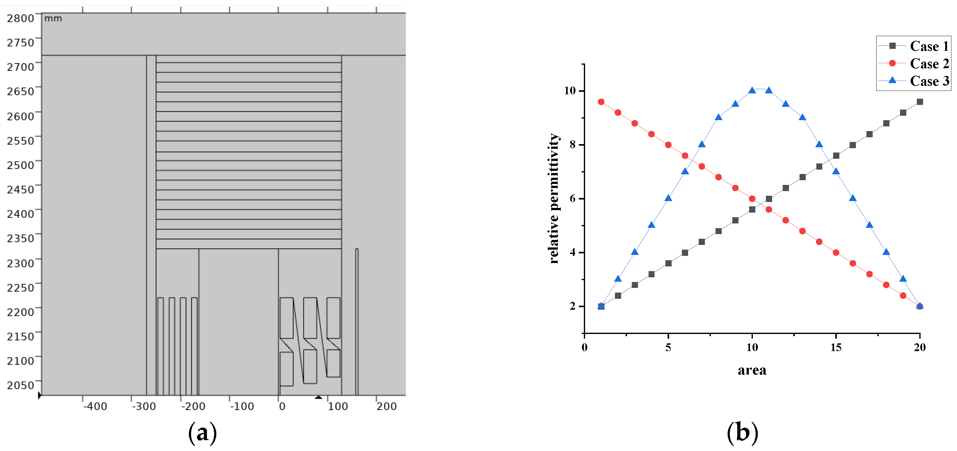
Figure 4.
Setting of functional graded materials for both spacers and winding ends: (a) Functional graded material setting diagram; (b) Functional graded material regulation method.
Figure 4.
Setting of functional graded materials for both spacers and winding ends: (a) Functional graded material setting diagram; (b) Functional graded material regulation method.
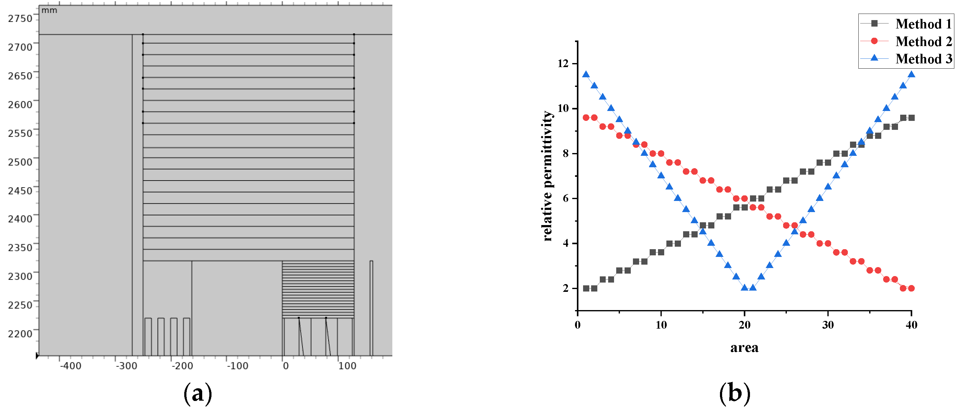
Figure 5.
Electric field cloud diagram without setting functional graded materials.
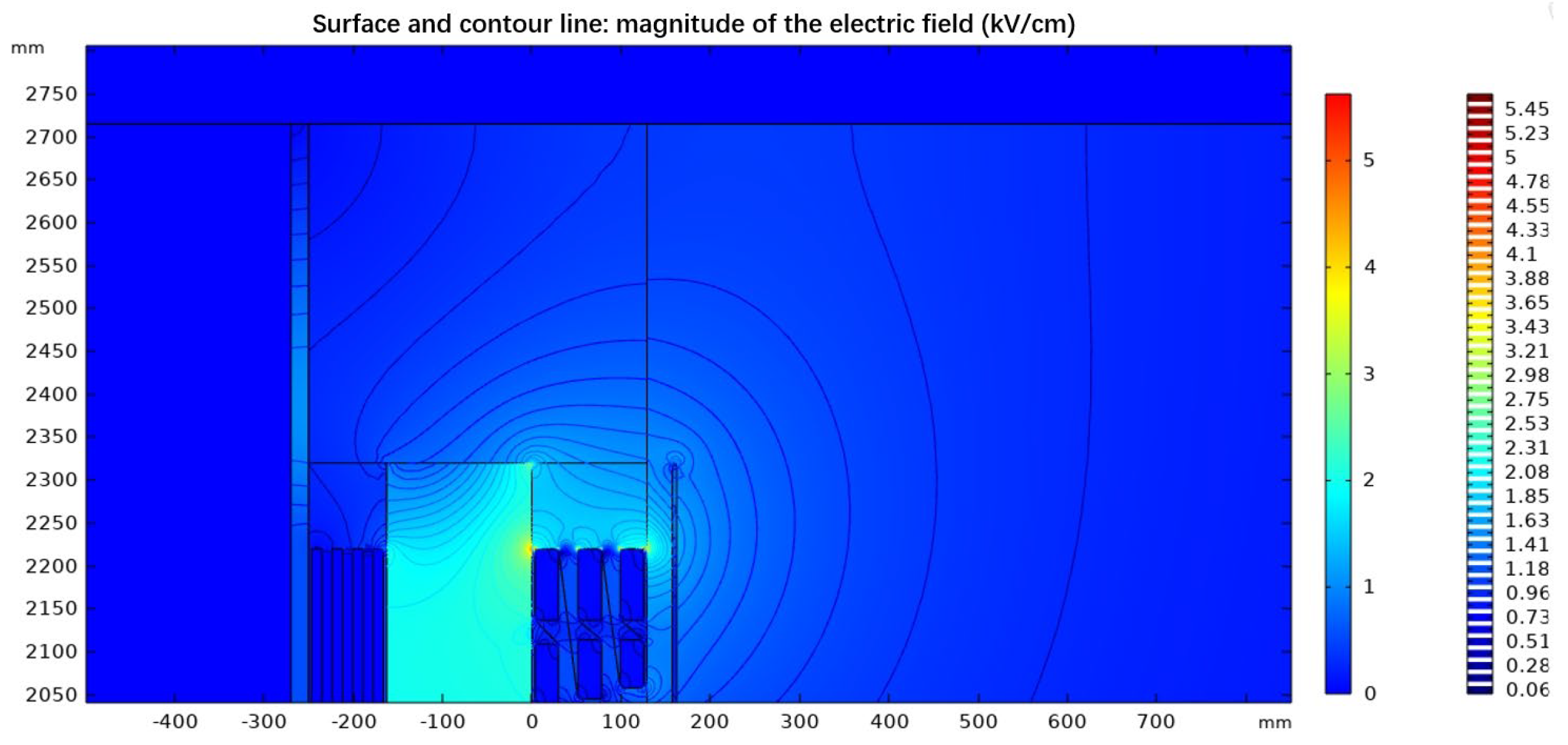
Figure 6.
Electric field cloud diagram when setting functional graded materials on transformer spacers under different conditions: (a) Case 1; (b) Case 2; (c) Case 3.
Figure 6.
Electric field cloud diagram when setting functional graded materials on transformer spacers under different conditions: (a) Case 1; (b) Case 2; (c) Case 3.
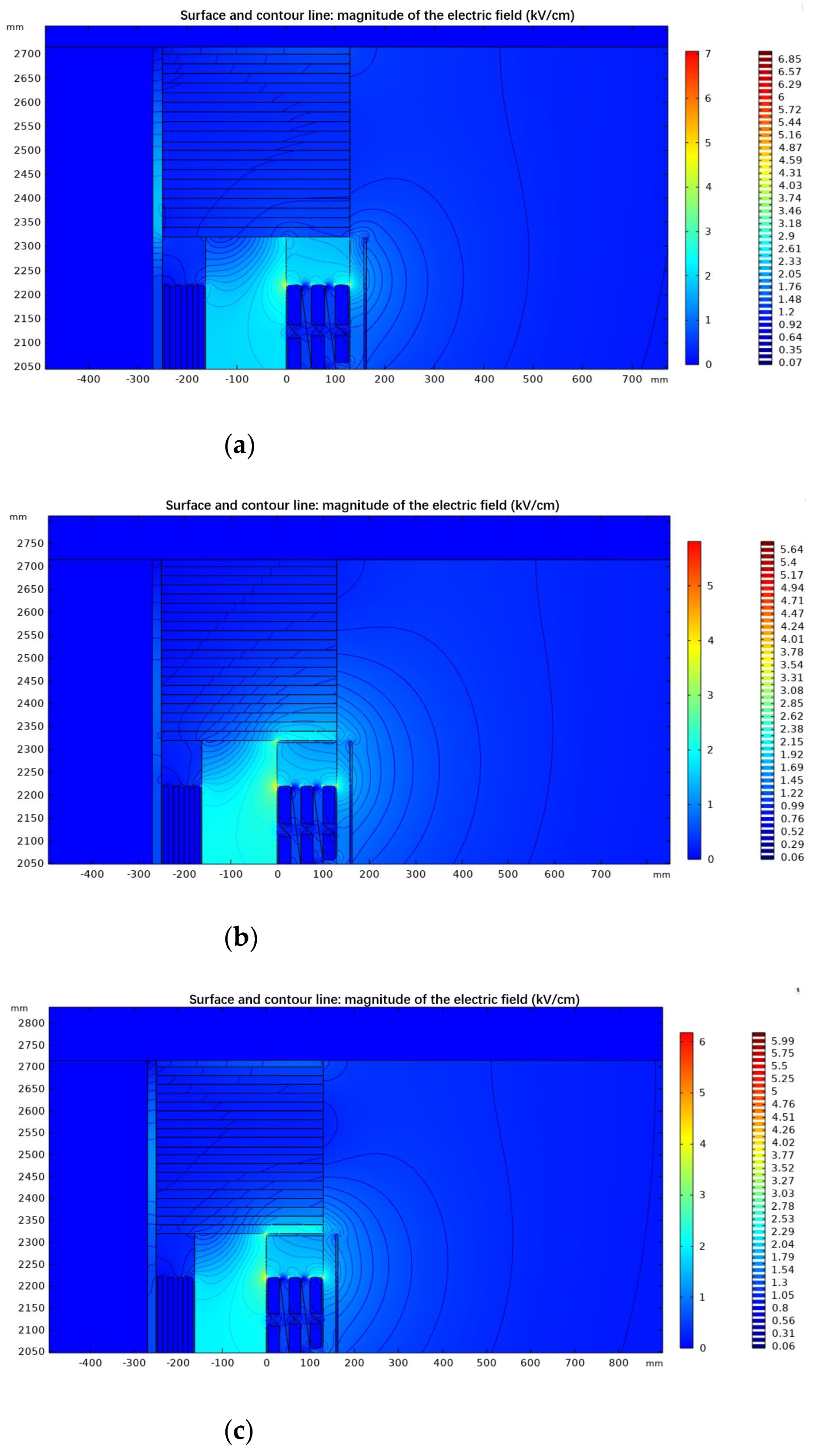
Figure 7.
Electric field cloud diagram when setting functional graded materials on transformer spacers and end windings under different conditions: (a) Method 1; (b) Method 2; (c) Method 3.
Figure 7.
Electric field cloud diagram when setting functional graded materials on transformer spacers and end windings under different conditions: (a) Method 1; (b) Method 2; (c) Method 3.
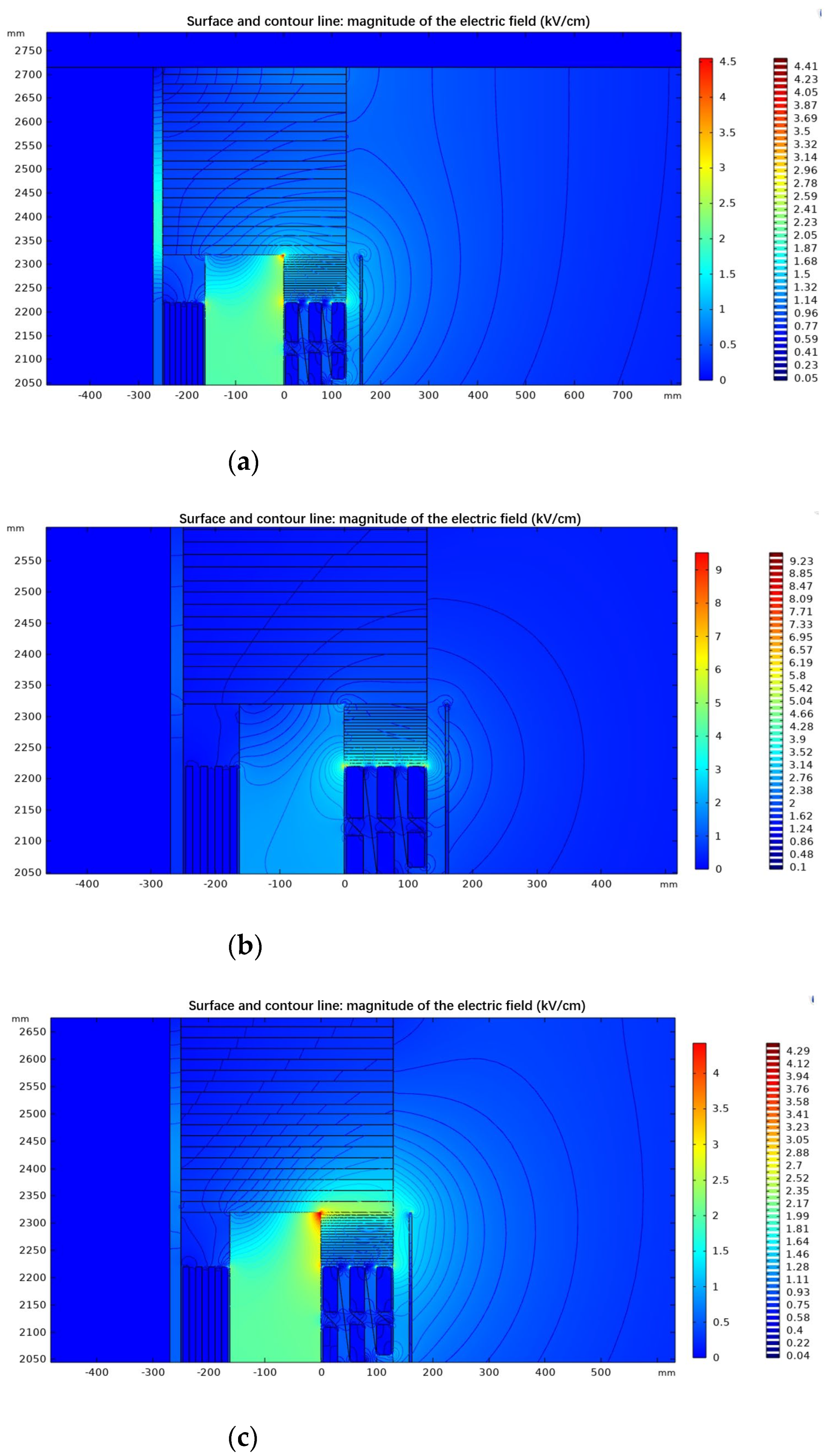

Table 1.
The relative permittivity of materials in the transformer.
| Material | Relative Permittivity |
|---|---|
| yoke | 8000 |
| spacer | 3.5 |
Table 2.
Summary of the impact of setting functional graded materials only on spacers on the electric field distribution.
Table 2.
Summary of the impact of setting functional graded materials only on spacers on the electric field distribution.
| Regulation method | Inner surface of high-voltage coil | Outer surface of high-voltage coil |
Bottom surface of spacer |
|||
|---|---|---|---|---|---|---|
| Maximum electric field strength |
Average electric field strength |
Maximum electric field strength |
Average electric field strength |
Maximum electric field strength |
Average electric field strength |
|
| Case 1 | +16.07% | 0% | +20.05% | +12.20% | -27.16% | -12.69% |
| Case 2 | +22.41% | -2.20% | +0.81% | +5.79% | +41.69% | +29.01% |
| Case 3 | +27.64% | -0.90% | +7.28% | +7.62% | +47.74% | +37.97% |
Table 3.
Summary of the impact of setting functional graded materials on spacers and end windings on the electric field distribution.
Table 3.
Summary of the impact of setting functional graded materials on spacers and end windings on the electric field distribution.
| Regulation method | Inner surface of high-voltage coil | Outer surface of high-voltage coil |
Bottom surface of spacer |
|||
|---|---|---|---|---|---|---|
| Maximum electric field strength |
Average electric field strength |
Maximum electric field strength |
Average electric field strength |
Maximum electric field strength |
Average electric field strength |
|
| Method 1 | +29.08% | -2.20% | -34.02% | -2.13% | +49.41% | +13.71% |
| Method 2 | +81.56% | -0.65% | +101.43% | +13.11% | +8.98% | -7.28% |
| Method 3 | +34.01% | -1.81% | -13.58% | +2.44% | +53.33% | +77.52% |
Disclaimer/Publisher’s Note: The statements, opinions and data contained in all publications are solely those of the individual author(s) and contributor(s) and not of MDPI and/or the editor(s). MDPI and/or the editor(s) disclaim responsibility for any injury to people or property resulting from any ideas, methods, instructions or products referred to in the content. |
© 2024 by the authors. Licensee MDPI, Basel, Switzerland. This article is an open access article distributed under the terms and conditions of the Creative Commons Attribution (CC BY) license (http://creativecommons.org/licenses/by/4.0/).
Copyright: This open access article is published under a Creative Commons CC BY 4.0 license, which permit the free download, distribution, and reuse, provided that the author and preprint are cited in any reuse.


