
Submitted:
18 October 2024
Posted:
18 October 2024
You are already at the latest version
Abstract
Reconfigurable Intelligent Surface (RIS), as an emerging radio technology, is widely used to expand transmission distance and structure cascade channels to improve the performance of communication systems. However, although RIS-NOMA assisted Internet of Vehicles (IoV) communication system can improve the overall transmission and rate performance with continuous development of wireless communication technology, the physical layer security (PLS) issue has gradually attracted attention and becomes more and more important in the application of the system. The aim of this paper is to investigate the potential threaten for PLS, when RIS is utilized in order to improve the security performance of wireless communications. In particular, this work considers the non-fixed of RIS location and wiretapping behavior of eavesdroppers on the data, and further analyzes the maximum safe-rate for above location assumptions. The results show that RIS demonstrates significant advantages on security performance and provides a useful reference for the security design of future wireless communication systems.
Keywords:
non-orthogonal multiple access (NOMA)
; reconfigurable intelligent surfaces (RIS)
; Internet of Vehicles (IoV)
; physical layer security (PLS)
; safe-rate
1. Introduction
With the development of vehicle networking system, wide transmission coverage, high energy efficiency and secure communication have become the primary tasks of evaluating vehicle networking communication system [1,2]. For the Internet of Vehicles (IoV), it can share information not only with infrastructure such as roadside units (RSU) through vehicle-to-infrastructure (V2I) communication, but also with vehicles through vehicle-to-vehicle (V2V) communication [3]. Automatic driving, intelligent driving-assist system, traffic flow and urban traffic management will bring exponential growth of massive data and computing resources consumption. Critical and real-time collaborative control messages have strict delay restrictions, while the transmission of multimedia entertainment application information can accommodate a certain degree of delay, which poses a great challenge for managing the interaction of vital information, task unloading and realizing large-scale model (LMs) based decision-making across many heterogeneous nodes within the framework of the Internet of Vehicles [4]. The wide application of the IoV based on artificial intelligence (AI) has aroused significant extensive concern about the IoV, which involves heterogeneous computing-intensive and delay-intolerant tasks. The on-board resources of consumer vehicles can not meet such requirements, so researchers introduced the technology of multiple access edge computing (MEC), which can expand the computing power of vehicle networks by allowing vehicles to offload some tasks to MEC servers. At this point, the authors in [5] minimize energy consumption, and develop a method based on deep reinforcement learning (DRL) to offload tasks to roadside units (RSU) or other vehicles. Similarly, the authors in [6,7] use the method based on DRL to unload tasks. In addition, the coverage of wireless communication networks based on high-cost base stations (BS) is still limited, and it is impossible to provide continuous, reliable and high-throughput basic services [8,9]. Therefore, there are obvious technical obstacles to realize reliable and extensible wireless transmission in IoV, which imposes great restrictions on the deployment of the above-mentioned intelligent vehicles and transportation systems.
RIS as a new communication technology can use a series of reflective elements to modulate electromagnetic wave signals and transmit them to the receiver, so it can effectively assist the communication between the transmitter and the receiver. For example, when the user is in an environment with poor communication quality, the RIS deployed in the surrounding area can reflect the signal to the required position to assist communication. Compared with the traditional antenna and base station technology, RIS has higher spectral efficiency, lower power consumption and better privacy [10,11]. In order to ensure low latency, the IoV needs ubiquitous ultra-reliable, low latency and high-speed wireless communication. In this respect, RIS assisted communication is a revolutionary way to improve the quality of wireless communication by adjusting the wireless propagation path [12]. RIS can reconstruct the wireless channel by using electromagnetic elements to manipulate incident waves, thus enhancing the system throughput and improving the quality of service (QoS) of edge users [13,14]. Although BS is the central hub of information exchange, they may not be able to achieve full coverage in urban application scenarios. Some RISs are deployed in a fixed configuration, while others are flexibly and adaptively configured by drones to adapt to the complexity of wireless channels [15,16,17]. On the basis of this framework, all vehicles in the IoV as terminal nodes can not only effectively transmit key information, but also offload local computing tasks to the edge or cloud server for processing. However, the hybrid architecture integrating RISs and BSs requires advanced hybrid beamforming, including digital beamforming for BS and analog beamforming for passive RIS, in order to maximize system throughput and reduce mutual interference. In addition, the combination of RIS and NOMA can further improve the performance of these systems.
In recent years, the rational use of secure channel capacity has become a focus of discussion among researchers and scholars [18,19], where the secrecy capacity of the transmitted data is investigated and the system is able to reach the maximum transmission rate between a legitimate transmitter and receiver, but this scheme is subject to the limitations of the information available to unauthorized receivers. The authors of [18] proved that for discrete memoryless channels, the perfect secrecy capability is actually the difference in capacity between two users and generalized similar results to Gaussian channels [20]. A study considered the case of full channel state information (CSI), where the transmitter has access to the channel gains of both the legitimate receiver and the eavesdropper, and this secrecy capacity under the full CSI assumption was used as an upper bound on the secrecy capacity when only the CSI of the legitimate receiver is known on the transmitter. The authors of [21] also proposed a low-complexity on or off power allocation scheme that achieves near-optimal performance using only the primary channel CSI. More specifically, the scheme is shown to be asymptotically optimal when the average signal-to-noise ratio (SNR) reaches infinity, achieving the secrecy capability assumed by full CSI. All the above studies show that channel fading has a positive effect on the secrecy capability and rate adaptation based on channel CSI. Therefore, PLS as a technology based on the physical characteristics of the communication channel to protect the security of the communication system has gradually become an important research direction in the field of information security. PLS techniques utilize the physical characteristics of the communication channel, such as signal attenuation, multipath propagation, and time-varying properties, to design security mechanisms that enhance the security of the communication system during the transmission of data [22]. Researchers are committed to continuously improving the performance and reliability of PLS techniques to cope with the increasingly complex and diverse security threats. And the features of PLS can effectively deal with some of the challenges faced by traditional cryptography, such as key management and side-channel attacks, as well as provide additional security guarantees. Currently, the common PLS schemes are non-orthogonal multiple access (NOMA) [24], artificial noise (AN) and cooperative jamming [25].
Since eavesdroppers are unable to decode the information correctly after eavesdropping the data, researchers often employ artificial noise generation at the transmitter to reduce the quality of the received data for eavesdroppers [26,27] and to improve the security and reliability of the communication system. For some application scenarios, real-time generation, injection and processing of artificial noise signals are required, which need to be supported by corresponding hardware resources, increasing the system cost and energy consumption, and in order to avoid excessive introduction of noise leading to degradation of communication quality or insufficient security enhancement. Recently, NOMA is considered as a promising technology, which can improve the spectrum and energy efficiency [28]. The advantage of NOMA is that it can accommodate more users on the same resource block, use superposition coding at the sending terminal and continuous interference cancellation at the receiving terminal [29], which can reduce the interference of users with better channel quality to users with weaker channel quality, thus improving user fairness and reducing the probability of channel blockage in the IoV. Based on various channel conditions required by NOMA, RIS can be used for intelligent control of random channels, which has been further discussed in recent research. However, most of these works do not consider the influence of the number of RIS components on the safe-rate of data transmission in detail under the NOMA principle.
In the RIS-NOMA assisted IoV communication system, the secrecy capability of the system can be greatly improved even in the presence of eavesdroppers. RIS can help to suppress the interference of communication signals by malicious eavesdroppers with adjusting the characteristics of the reflected signals and improving the security of the system [30]. RIS can also help to optimize the transmission path of the signals to reduce the signal leakage and the possibility of eavesdropping, as well as enhance the security of the channel links. In previous studies, the location of RIS is often fixed and unchanged, and it is not considered that the location change of RIS not only affects the quality of data transmission to users, but also further affects the overall safe-rate and performance of data transmission in the presence of eavesdroppers. For this reason, it is necessary to explore the impact of RIS location changes on the overall security rate of the system so as to maximize the security rate of data transmission for legitimate users.
- We propose a RIS-NOMA system consisting of remote users, near users and eavesdroppers, in which eavesdroppers wiretap on the transmission source data. The maximum security rate under different RIS positions is analyzed.
- The balance between RIS deployment location and channel security rate is studied, and the fixed locations of far and near users are considered, respectively.
- Numerical results verify the correctness of our analysis as well as the effectiveness of the proposed scheme, providing a significant improvements in terms of safe-rate.
2. System Model and Proposed Scheme
This work considers a RIS-NOMA-assisted secure communication system model, as shown in Figure 1, which consists of the transmitting source (S), RIS, two legitimate users , and the eavesdropper E. For the channel model, we assume that all nodes are equipped with single antenna, considering that S and are known to the eavesdropper to wiretap on the desired data X within a long distance. With , the valid data received by is , and the valid data received by is . Clearly, since the data received by and are both on the broadcasting channel, the safe-rate is extremely low. Considering the element size of RIS is much smaller than the RF signal wavelength, thus the elements are able to reflect the incident signal to each direction with constant gain. Furthermore, each element of the RIS is intelligently controllable, and the reflecting elements can control the phase shift.
In the system model of Figure 1, the direct channels from S to RIS, user , user and eavesdropper E are respectively expressed as , the reflection channel of RIS is . In the model, user is considered to be farther away from the transmitter than user , so the channel gain of is considered to be less than , and represents the norm of the vector. The angle of the RIS deployment position relative to the emission source is in [0,180]. Because the NOMA scheme will actively consider the fairness of users, there will be differences in setting power distribution coefficients. The power distribution factors of service user and user are and , , and the transmission data at S is , where and are the expected signals of and , respectively.
2.1. Power Allocation Discussion
2.1.1.
In this section, to ensure fairness among users, we discussed power allocation with two different situations. When , RIS is equipped with n fixed elements to serve different users with the same number of elements. The channel gains from the transmitter S to RIS and from RIS to user are . Similarly, the channel gains from S to RIS and RIS to can be expressed as . In addition, it is assumed that all channels experience Rayleigh fading distribution, and the signals received by users and can be expressed as
where P is the transmission power at S, and are the transmitted data, , and the phase shift matrix of RIS at user is . The phase shift matrix at user is , is amplitude reflection coefficient. The additive white Gaussian noise (AWGN) at both and is characterized by a mean value of zero and a variance of .
In the communication system assisted by RIS-NOMA, according to the decoding principle of NOMA, user will first decode with as interference. After successfully decoding , user decodes through SIC. Therefore, the SNRs of user and user can be respectively given as
Similarly, the SNR of eavesdropper is , . Therefore, the achievable rates for received data and data are respectively expressed as
where is the expected value of x, the eavesdropping rates on data and data by eavesdropper is as follow
Finally, the secrecy rate of data and data can be further obtained as
where . Then the secrecy sum-rate of data can be obtained
In the communication system with NOMA, in order to ensure fairness, a larger power allocation factor will be assigned to the poor channel, and . When , the user is closer to the transmitting source, and when , the channel gain can be expressed as . Therefore, it can be further deduced from Equations (3)–(5) as , , so Equation (11) can be rewritten as follows
Thus Equation (12) can be further written as
2.1.2.
In this condition, it can be deduced from Equations (3)–(5) as
so it can be further calculated , and . Therefore, the secrecy rate of data and can be expressed as
where , then the secrecy rate can be obtained as
Considering the simple calculation, the Equations (19) and (20) can be directly substituted into Equation (23) as
3. Performance Analysis
In this section, because the location of RIS is not fixed, the channel quality of user and user will also change in the process of continuous movement, thus affecting the change of secrecy rate. In the communication system assisted by RIS-NOMA, since the fairness of users should be guaranteed when transmitting data, the change of RIS position will also affect the distribution of channel power by NOMA, so the secrecy rate of the channel is a topic worthy of further discussion. This problem can be solved by simply considering the change of channel secrecy rate when different power allocation factors are used.
3.1. Ideal Phase Case
It is assumed that the phase shift is optimal, Specifically, can be rewritten as
From Equation (25), it can be verified that is with a optimal result when , which implies that the phase shift for both the direct link between source and destination, as well as the cascaded link is equivalent as . Specially, and ,Therefore, the optimal phase shift can be obtained
Combining the direct channel and the reflection channel, the sum channel gains from source to and can be simplicity expressed as
where , . From the previous chapter, it can be seen that if the Equation (23) is directly substituted into the Equation (22), it will be difficult to simplify and increase the complexity of calculation. Let be the transmission SNR, because the proposed system works under the condition of high SNR by default, so with the condition of , the approximation of can be used. Therefore, available , substitution into the Equation (17) can give a simplified formula as
Since , we can further deduce . Similarly, when , we can get . It is clear that, for and , x is constantly bigger than 0. Therefore, according to Jensen’s inequality, for the concave function , an explicit closed-form expression for the upper bound of the channel capacity can be derived as
3.2. Non-Ideal Phase Case
In practice, due to the hardware limitation, the RIS can not achieve ideal phase. Thus, for , we have
The corresponding capacity is given by , we attempt to get the ergodic capacity, So , it is obviously that following the exponential distribution with parameters and . Where the , and obey Rayleigh fading with parameters , for i = . The secrecy rate of in can thus be obtain from
4. RIS Deployment Analysis
In this section, we can analysis the influence to RIS-NOMA assisted IoV system with uncertain RIS deployment. Assuming that the channel gain is , and the path loss is , leading to . In the same way, we have , , . By substituting above results back into Equation (27), we have
Since the deployment position of RIS and the distance from RIS to S are variable, by means of the Cosine Theorem, the distance from RIS to user can be expressed as
as well as, the distance from RIS to user is
Clearly, if direct membership makes the formula very complicated, where and are variables, Taylor expansion can be adopted to solve such problem, and the binary Taylor formula is
where . Letting and be x and y, respectively, we can get
Let and , which can be obtained after substitution in the formula and simplification as
Let and , which can be obtained after substitution in the formula and simplification as
Substituting the function values of and , we can obtain
5. Numerical Results
In this section, the performance of the proposed system is evaluated by numerical results. Assuming that all channels follow Rayleigh fading, the path loss index is set to 2.2. For simplicity, the position of each node is set to .
Figure 2 shows the relationship between the total safe-rate of data transmission and the angle of RIS position relative to the transmitter. In the proposed scheme, the transmission power is dBm, and the number of reflective elements is fixed at 1000. As can be seen from the display results in the figure, when , the safe-rate will gradually decrease with the increase of the distance between RIS deployment location and user , when the security rate of data transmission will gradually increase with the decrease of the distance between RIS deployment location and user . In the simulation, it can be found that there is an intersection between the security rates of data transmission, which is . When RIS is at this angle, the security rates of the two are equal under different power factor allocation mechanisms, it is also the lowest value of the safe-rate, and the security at this time is the most unreliable. When it is less than this angle, the data will be transmitted by the power distribution factor transmission mode of . When it is larger than this angle, the data will be transmitted in the transmission mode of .
Figure 3 shows the relationship between the safe-rate and the deployment position of RIS. When the RIS is gradually away from the user , the transmission rate of data gradually decreases. While the eavesdropper directly eavesdrops on the data of S, the eavesdropping rate will not change due to the change of the deployment position of RIS, but the change of the position of RIS has little influence on the transmission rate of data , because under the NOMA principle, will be decoded. Furthermore, the safe-rate of the total data transmitted is similar to that of the data . Similarly, when the RIS gradually approaches the user , its channel quality gradually passes the user , thus changing the power factor distribution of the channel, and the safe-rate will gradually increase after crossing the point. In this paper, the simulation assumes that the initial states are all on the same level with users , and S.
Figure 4 shows that when the S is fixed and the distance between RIS and S is changed, the performance of safe-rate is different. Assuming that the distances from S to RIS are 20m, 30m and 40m respectively, it can be seen that the safe-rate is gradually improved as the deployment position of the RIS is closer to the S. This is because when the deployment position of RIS is close to the S, the path loss decreases and the channel quality of the cascaded channel is improved, so the safe-rate will increase with the decrease of the distance from the S. The changing trend of the curve in the figure is that the RIS gradually moves away from the user , which weakens the data transmission quality of the RIS service user channel, so the safe-rate of data will decrease with the increase of the angle. Similarly, because the deployment position of RIS is gradually close to user , the safe-rate of data will gradually increase with the increase of the deployment angle of RIS relative to the S.
Figure 5 shows the influence of increasing the number of RIS elements on the safe-rate of data when S is fixed. Assuming that the number of elements of RIS is 1000, 1500 and 2000 respectively, it can be seen from the graphic information that the safe-rate is more reliable with the increase of the number of RIS distribution elements, and it can be seen that the safe-rate is gradually improved with the deployment position of RIS getting closer to the S. This is because when the number of elements of RIS increases, the channel quality of the cascade channel is enhanced, so the safe-rate will increase with the increase of RIS elements number. The changing trend of the curve in the figure is that the RIS gradually moves away from the user , which weakens the data transmission quality of the RIS service user channel, so the safe-rate of data will decrease with the increase of the angle. Similarly, because the deployment position of RIS is gradually close to user , the safe-rate of data will gradually increase with the increase of the deployment angle of RIS relative to the S.
Figure 6 shows the influence on the safe-rate of data when the S is fixed and the transmission power is increased. Assuming that the transmission power is 1dBm, -3dBm and -6dBm respectively, it can be seen that with the increase of the transmission power, the safe-rate is more reliable. This is because when the transmission power increases, the channel quality of the cascade channel is enhanced, so the safe-rate will increase with the increase of the transmission power. The changing trend of the curve in the figure is that the RIS gradually moves away from the user , which weakens the data transmission quality of the RIS service user channel, so the safe-rate of data will decrease with the angle increase. Similarly, because the deployment position of RIS is gradually close to user , the safe-rate of data will gradually increase with the increase of the deployment angle of RIS relative to the S.
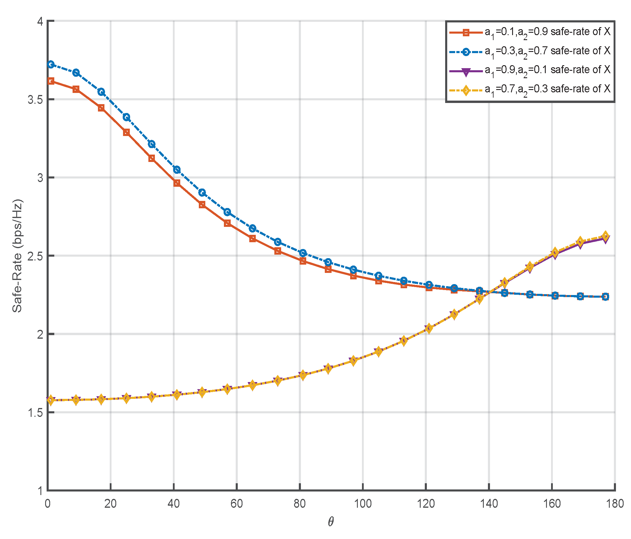
Figure 7 shows the relationship between the power allocation factor coefficient and the angle of RIS relative to the S. In the proposed scheme, the power is dBm and the number of RIS elements is fixed at 1000. It can be seen from the display results in the figure that when the power allocation factor coefficient changes, it will not have a great influence on the trend of the simulation curve. When , the safe-rate of data transmission will gradually decrease with the increase of the distance between the RIS deployment position and the user . While , the safe-rate of data transmission will gradually increase with the decrease of the distance between the deployment position of RIS and the user . In the simulation, it can be found that even if the power allocation factor coefficient changes, the intersection point of the safe-rate of data transmission will not change, and the lowest value of the safe-rate will not change. Because there is no power allocation factor in Equation (36), and the simulation results also verify the correctness of the formula derivation.
6. Conclusions
This paper discusses the PLS of RIS-NOMA system under the condition of uncertain RIS location, aiming at improving the safe-rate of data transmission under different channel conditions. In RIS-NOMA system, RIS provides services for user, while eavesdroppers try to eavesdrop on the data of source. It is worth noting that the deployment position of RIS is not fixed, but changes within a certain range. In this paper, the equivalent safe-rate of two users is obtained through data analysis. In addition, this paper also deduces the minimum safe-rate required under different deployment angles of RIS relative to the source. Numerical results verify the analysis correctness and show the superiority of the proposed scheme compared with the existing schemes. Through further simulations, the potential advantages of the RIS-NOMA system under the condition of uncertain RIS position are shown, and useful guidance is provided for actual deployment.
References
- L. Liu, J. Feng, X. Mu, Q. Pei, D. Lan, and M. Xiao. Asynchronous deep reinforcement learning for collaborative task computing and on- demand resource allocation in vehicular edge computing. IEEE Trans. Intell. Transp. Syst. 2023, 1–14.
- Y . Ni, L. Cai, J. He, A. Vinel, Y . Li, H. Mosavat-Jahromi, and J. Pan. Toward reliable and scalable internet of vehicles: Performance analysis and resource management. Proc. IEEE. 2020, 108(2), 324–340.
- J. Zhang and K. B. Letaief. Mobile edge intelligence and computing for the internet of vehicles. Proc. IEEE. 2020, 108(2), 246–261.
- H. Li, K. Ota, and M. Dong. Learning iov in 6g: Intelligent edge computing for internet of vehicles in 6g wireless communications. IEEE Wireless Commun. 2023, 30(6), 96–101.
- B. Hazarika, K. Singh, S. Biswas, and C.-P . Li. Drl-based resource allocation for computation offloading in iov networks. IEEE Trans. Industr. Inform. 2022.
- S. A. Kazmi, T. M. Ho, T. T. Nguyen, M. Fahim, A. Khan, M. J. Piran, and G. Baye. Computing on wheels: A deep reinforcement learning- based approach. IEEE trans. Intell. Transp. Syst. 2022.
- J. Shi et al. Drl-based v2v computation offloading for blockchain- enabled vehicular networks. IEEE Trans. Mob. Comput. 2022.
- J. Wang, H. Ke, X. Liu, and H. Wang. Optimization for computational offloading in multi-access edge computing: A deep reinforcement learning scheme. Comput. Netw. 2022, 108690.
- J.-X. Chen, T.-Y. Yan, J.-Y. Yang, X.-H. Ding, L.-L. Yang, and Y. Li. Dual-polarized heterogeneous stacked patch antenna with stable radiation performance and high efficiency. IEEE Antennas Wireless Propag. Lett. 2024, 23(8), 2421–2425.
- L. Dai, R. Jiao, F. Adachi, H. V . Poor, and L. Hanzo. Deep learning for wireless communications: An emerging interdisciplinary paradigm. IEEE Wirel. Commun. 2020, 27(4), 133–139.
- Z. Yao, W. Cheng, W. Zhang, and H. Zhang. Resource allocation for 5g-uav-based emergency wireless communications. IEEE J. Sel. Areas Commun. 2021, 39(11), 3395–3410.
- Y . Zhang, K. Shen, S. Ren, X. Li, X. Chen, and Z. Q. Luo. Config- uring intelligent reflecting surface with performance guarantees: Op- timal beamforming. IEEE J. Sel. Topics Signal Process. 2022, 16(5), 967–979.
- C. Zhang, M. Dong, and K. Ota. Heterogeneous mobile networking for lightweight uav assisted emergency communication. IEEE Trans. Green Commun. Netw. 2021, 5(3), 1345–1356.
- B. Wang, Y . Sun, Z. Sun, L. D. Nguyen, and T. Q. Duong. Uav- assisted emergency communications in social iot: A dynamic hypergraph coloring approach. IEEE Internet Things J. 2020, 7(8), 7663–7677.
- Y . Lin, T. Wang, and S. Wang. Uav-assisted emergency communi- cations: An extended multi-armed bandit perspective. IEEE Commun. Lett. 2019, 23(5), 938–941.
- Kafafy M, Ibrahim A. S, Ismall M. H. Uplink Power Analysis of RIS-assisted Communication Over Shared Radar Spectrum. 2022 5th International Conference on Communications, Signal Processing, and their Applications (ICCSPA). 2022, 1–5.
- L. Xu, X. Zhou, Y. Tao, et al. AF Relaying Secrecy Performance Prediction for 6G Mobile Communication Networks in Industry 5.0. IEEE Trans. on Indus. Inform. 2022, 18(8), 5485–5493.
- Andrawes A, Nordin R, Ismail M. Energy harvesting with cooperative networks and adaptive transmission. 2017 IEEE Jordan Conference on Applied Electrical Engineering and Computing Technologies (AEECT). 2017, 1–6.
- J.-X. Chen, J.-Y. Yang, X.-H. Ding, T.-Y. Yan, Y.-L. Li, and W.-W. Yang. A microwave/millimeter-wave shared-aperture fitering antenna with reused via structure. IEEE Trans. Antennas Propag. 2024,72(9), 7377–7382.
- Praveen Kumar G, Lifeng Lai, Hesham El G. On the Secrecy Capacity of Fading Channels. IEEE Trans. Inform. Theory. 2008, 54(6).
- Mi-Kyung OH, Sangjae Lee, Yousung Kang, et al. Wireless Transceiver Aided Run-Time Secret Key Extraction for IoT Device Security. IEEE Trans. Consu. Elec. 2020, 66(1).
- L. Sun, Q. Du. Physical layer security with its applications in 5G networks: A review. China Communications. 2017, 14(2).
- Milad Tatar M, Ali Kuhestani, Hamid Behroozi. Can a multi-hop link relying on untrusted amplify-and-forward relays render security? Wireless Networks. 2020.
- C. Wang, Z. Li, X. Xia, et al. Physical Layer Security Enhancement Using Artificial Noise in Cellular Vehicle-to-Everything (C-V2X) Networks. IEEE Trans. Vehi. Tech. 2020, 69(12).
- Y. Liu, Z. Su, Y. Wang. Artificial Noise-Assisted Beamforming and Power Allocation for Secure D2D-Enabled V2V Communications. 2021 IEEE 94th Vehicular Technology Conference (VTC2021-Fall). 2021, 01–05.
- X. Li, J. Li, Y. Liu, et al. Residual Transceiver Hardware Impairments on Cooperative NOMA Networks. IEEE Trans. on Wire. Commun. 2020, 19(1), 680–695.
- Jeffrey G. Interference cancellation for cellular systems: a contemporary overview. IEEE Wire. Commun. 2005, 12(2).
- T. Hou, Y. Liu, Z. Song, et al. Reconfigurable Intelligent Surface Aided NOMA Networks. IEEE Journal on Selected Areas in Communications. 2020, 38(11), 2575–2588.
- Z. Ding, Vincent Poor H. A Simple Design of IRS-NOMA Transmission. IEEE Comm. Lett. 2020, 24(5), 1119–1123.
- Y. Zhang, G. Zhang, S. Chen, et al. Optimal Element Allocation for RIS-Aided Physical Layer Security. Wireless Communications and Mobile Computing. 2022, 1–7.
Figure 1.
RIS-NOMA assisted wireless network security communication system model.
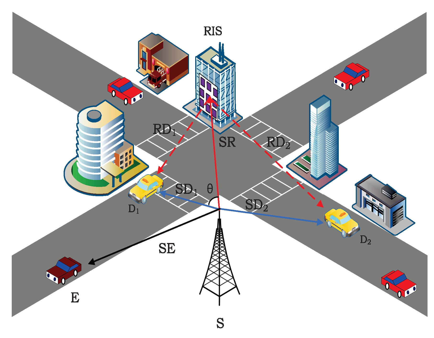
Figure 2.
Relationship between safe-rate and deployment location of RIS.

Figure 3.
Relationship between data safe-rate and RIS deployment location.

Figure 4.
Influence of RIS relative system deployment spacing on data safe-rate.
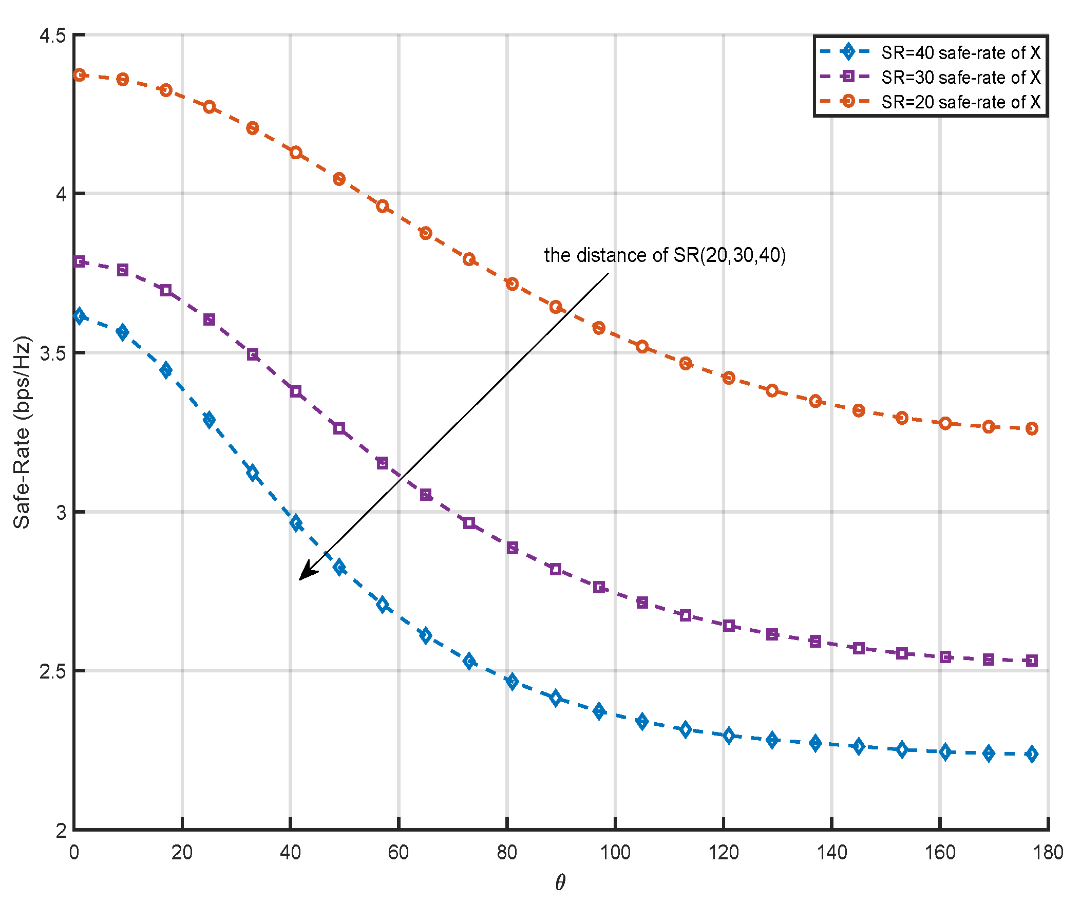
Figure 5.
The data safe-rate of the system and the number of reflective elements.
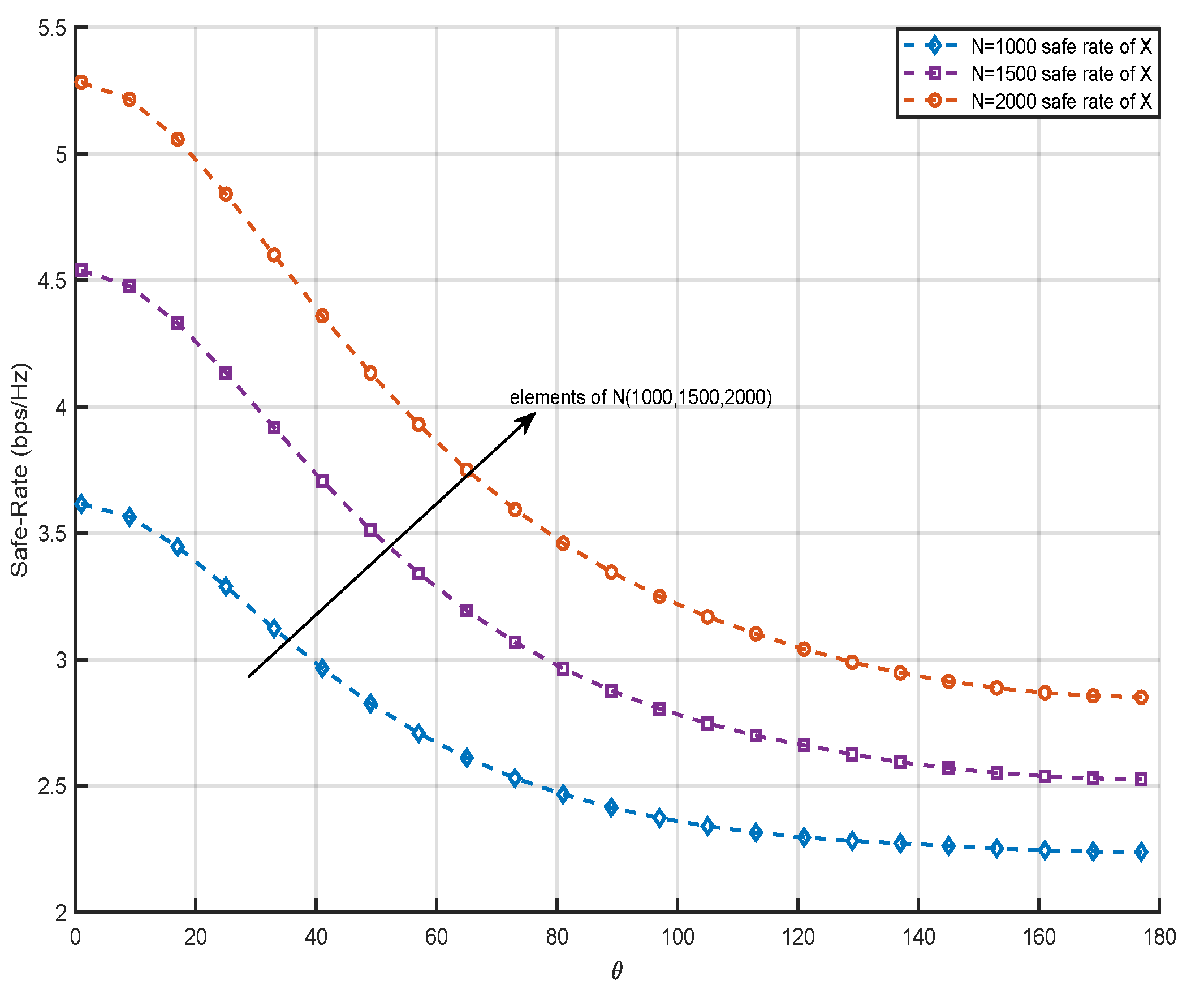
Figure 6.
Relationship between safe-rate of data and transmission power.
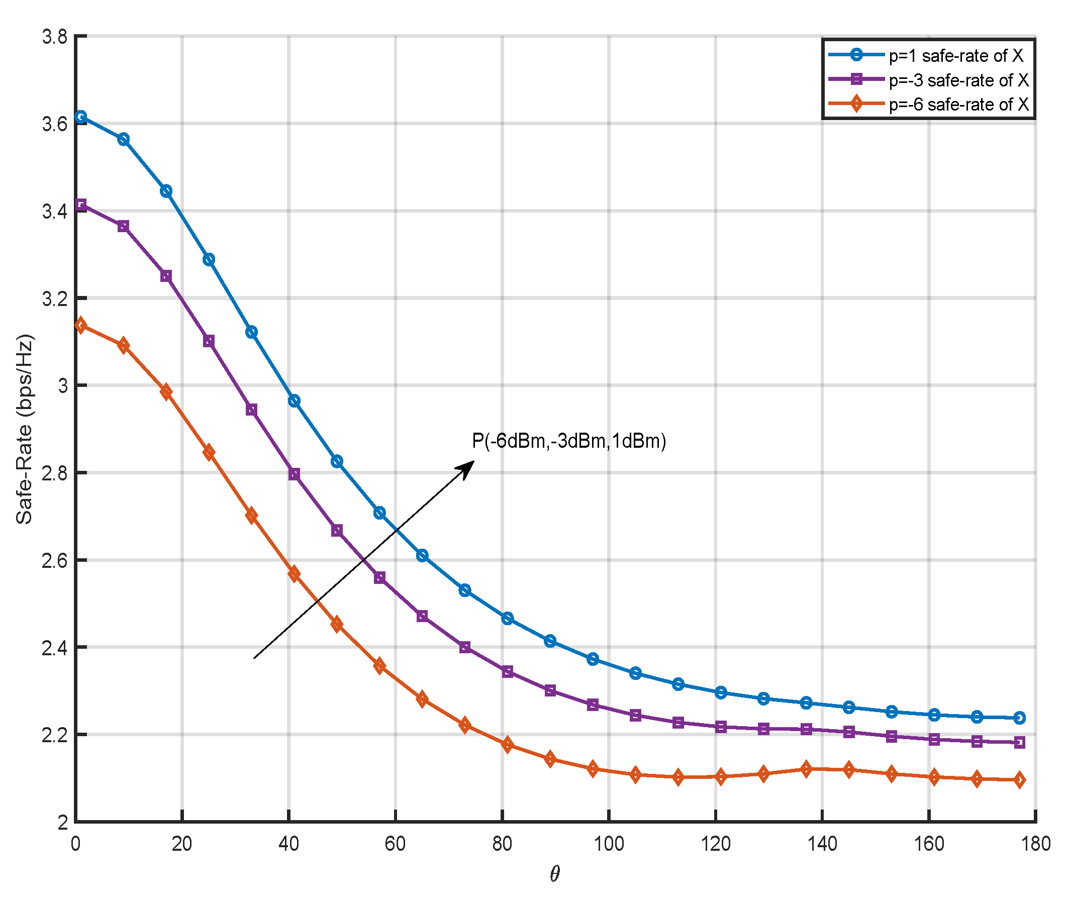
Figure 7.
Relationship between safe-rate and power allocation factor.
Disclaimer/Publisher’s Note: The statements, opinions and data contained in all publications are solely those of the individual author(s) and contributor(s) and not of MDPI and/or the editor(s). MDPI and/or the editor(s) disclaim responsibility for any injury to people or property resulting from any ideas, methods, instructions or products referred to in the content. |
© 2024 by the authors. Licensee MDPI, Basel, Switzerland. This article is an open access article distributed under the terms and conditions of the Creative Commons Attribution (CC BY) license (http://creativecommons.org/licenses/by/4.0/).
Copyright: This open access article is published under a Creative Commons CC BY 4.0 license, which permit the free download, distribution, and reuse, provided that the author and preprint are cited in any reuse.


