

Submitted:
11 October 2024
Posted:
11 October 2024
You are already at the latest version
Abstract
This research introduces a novel approach to improving wind energy's LCOE (Levelised Cost of Energy). Specifically, this research aims to reduce the LCOE from wind turbines by investigating a novel Active Axis Wind Turbine (AAWT) design. The turbine is neither a horizontal nor vertical axis wind turbine but has an axis of operation that can actively change during operation. The design features a rotor with a single blade capable of dynamic pitch and tilt control during a single rotor rotation. This study examines the potential to balance the centrifugal and aerodynamic lift forces acting on the rotor blade assembly, significantly reducing blade, tower, foundation and infrastructure costs in larger-scale devices and decreasing the LCOE for wind. The design of a laboratory prototype rotor assembly is optimised by varying the masses and lengths in a lumped mass model to achieve equilibrium between centrifugal and lift forces acting on the turbine's rotor assembly. The method involves an investigation of the variation of blade pitch angle to provide a balance between centrifugal and aerodynamic forces, thereby facilitating the cost advantages and opening the opportunity to improve the turbine efficiency across a range of operation conditions. The implication of this study extends to different applications of wind turbines, both onshore and offshore, introducing insight into innovation for sustainable energy and cost-effective solutions.
Keywords:
wind energy
; active axis wind turbine
; lift and centrifugal forces
; lumped mass
1. Introduction
Owing to concern over global warming and climate change, power generation from renewable resources has obtained much interest in recent decades [1]. Wind energy is one of the most promising renewable energy sources for energy production for several reasons, including the availability of sustainable resources, decreasing cost, and advanced technology, which has minimal environmental effects [2,3,4]. There have been a variety of designs over the years, but all wind turbines can be classified as either horizontal-axis wind turbines (HAWTs) or vertical-axis wind turbines (VAWTs). Of these, the HAWT has been by far the most commercially successful. Figure 1a,b show the main components of a HAWT and a VAWT, respectively.
HAWTs have higher powertrain efficiency than VAWTs, making HAWTs more efficient in energy conversion and more competitive in the market for both onshore and offshore applications during the last 30 to 40 years [7]. The aerodynamic performance of HAWTs is scalable, as proved in aerodynamic theory. However, the greatly increased mass at the top of the rotor deteriorates the upscaling behaviour of the turbine system because the increased weight due to the larger rotor size is greater than the increased aerodynamic load [7]. Due to this, the upscale limit of a HAWT is around 30 MW [6]. Cyclic gravitational loading causes stress problems on blades and other parts of the turbine structure. On a wind turbine rotor, thrust is the main source of aerodynamic force and is directly proportional to the square of the hub-height wind speed. Modern wind turbines require larger concrete and steel foundations to withstand the high overturning moments computed by multiplying the thrust force by the hub height, which, in modern turbine towers, can be over 100 m. The supporting infrastructure in the form of these foundations may significantly impact the total installed cost of the turbine. Blair Loftis [8] states that utility-scale wind farms cost approximately around $2 million for each installed turbine. About seventeen percent of the utility-scale cost is related to the turbine foundation. The foundation expenses for offshore wind turbines are much greater, ranging from around 20% for water depths of 10–20 meters to 36% for ocean depths of 40–50 meters [9]. Using floating platforms can lower the cost of an offshore foundation. Still, the high centre of mass of heavy-nacelle HAWTs atop tall towers necessitates using large area floating structures for stability.
VAWTs have some special advantages because of their inherent characteristics. For example, the operation of a VAWT is independent of wind direction (omnidirectional), and VAWTs operate without a yawing system, unlike HAWTs, which need to track the changing wind direction continuously. Further, VAWTs can have a simple blade design with low noise, and the mechanical and electrical equipment, such as generators and drivetrains, are easily accessible because they are ground-based and easy to maintain [10]. An important distinction between offshore VAWTs and HAWTs is that due to the ground-based location of heavy machinery components, VAWTs have a lower centre of gravity and wind load, enhancing structural stability. For offshore wind turbines on floating platforms, this lessens the likelihood of the platform overturning, leading to the possibility of smaller platform sizes and spacing. Consequently, a smaller mooring system will be needed for the reduced foundation. Any decrease in the hull and mooring system size, and thereby cost, is significant because the cost of the floating foundation is a major contributor to the total cost of floating wind turbines [11]. For these reasons, a recent surge has emerged in VAWT research concerning commercial offshore designs [12,13,14].
Despite the advantages mentioned above, VAWTs encounter several challenges. For example, Darrieus VAWTs face disturbed airflow in the downwind pass of the rotor blade because of turbulence created in the upstream pass and shed downstream [15,16]. This decreases the aerodynamic efficiency of the turbines and makes them less effective than HAWTs. Also, VAWTs are associated with a weak self-starting capability. Finally, there is high cyclic loading in Darrieus VAWTs because of the fluctuating acting forces on the blades. These fluctuations generate fatigue and increase capital costs associated with turbine design [17]. On the upward pass, the centrifugal and the aerodynamic forces act in opposite directions, whereas on the downward pass, these forces act in the same direction. Due to this imbalance, VAWTs need additional support structures, such as struts, to stabilise the rotor. This adds more materials and costs to the turbine [18].
Table 1 summarises the main comparable aspects of HAWTs and VAWTs.
1.1. Introduction to the Active Axis Wind Turbine (AAWT)
With these limitations in both HAWTs and VAWTs, there is a need for innovation to harness the advantages, address the disadvantages of both types and introduce a new type that could significantly reduce the levelized cost of energy (LCOE) for wind. The AAWT is a novel type of wind turbine that potentially achieves these goals by lowering the required support infrastructure and increasing aerodynamic efficiency. The AAWT consists of a rotor with a single blade that can be pitched and tilted synchronously as a function of the azimuth angle. Thus, the AAWT turbine can actively tilt the rotor’s rotation axis to an incline rather than fixing it horizontally or vertically. The design of this turbine is specifically directed toward:-
- Reducing the substantial infrastructure required to cope with large overturning forces acting on HAWTs and VAWTs
- Balancing the aerodynamic and centrifugal forces acting on the wind turbine blade to enable longer spans, reduced mass and lower cost
- Minimising blade flight through areas of lower velocity, lower energy downwind or disturbed air and specifically addressing the lower efficiency associated with VAWTs.
- Allowing cost-effective floatation and anchoring systems to be used in offshore floating wind turbine installations
This research is part of a larger project that involves developing the AAWT. The project’s first phase is to construct a small laboratory prototype, a proof-of-concept AAWT, with a blade that is 920 mm in span, 120 mm in chord and weighs 115 grams.
The research question of this paper is whether the AAWT can be designed so that the centrifugal and normal aerodynamic forces can be balanced sufficiently to achieve a satisfactory fight path during each rotation. If this can be achieved, the required support infrastructure could be reduced by reducing the size of foundations and removing items such as towers and supporting stays and the blade chord and span can potentially increase. Based on the literature research, no studies directly discuss balancing centrifugal and normal aerodynamic forces to decrease load and costs in VAWT operation. However, in HAWT designs, the rotor is sometimes coned downwind to decrease the flapwise bending moment, using the centrifugal force on the blade to counter the normal aerodynamic force [23,24]. Further investigations examining how to achieve equilibrium between these forces and the impact on an AAWT’s design would be beneficial. This paper presents a design study that constructs an aerodynamic model for the AAWT, which neglects any external wind for simplification. Aerodynamic force is generated on the blade via pitching the rotating blade. Because the scale of the blade is small, it needs to be lightweight for the centrifugal force to balance the small aerodynamic force. A lumped mass analysis is used to aid in designing the required weight and locations of the AAWT’s various components and examines their contribution to the net centrifugal moment. An optimisation approach using Python code was developed employing the Sequential Least Squares Programming (SLSQP) method to provide optimum component masses and distances from the centre of rotation. This optimisation seeks to achieve the necessary equilibrium, balancing the centrifugal and aerodynamic moments under various blade pitch angles and at different tilt angles.
The structure of this paper is as follows: section two provides a theoretical explanation of VAWT aerodynamics (as background for the forces on the AAWT), while section three includes the methodology followed by the lumped mass model. The fourth section covers the results and discussion, summarising the conclusion in section five.
2. Theoretical Background
This theory relates to an H-rotor VAWT but gives a suitable background for the AAWT described in Section 3.
Figure 2 illustrates the velocity vectors’ aerodynamic notation and the forces on the rotor blades of an H-rotor VAWT. The wind velocity at the blade, Vind, is less than the incoming freestream flow velocity, V, due to the slowdown on the freestream by the blade. As the rotor extracts energy from the wind, the tangential velocity of the blade is:
Where ω is the rotor’s angular velocity, and R is the radius of the rotor. The relative velocity, Vrel, results from the vector addition of the wind velocity on the turbine and tangential velocity. This study calculates the relative wind velocity based on the cosine rule of the angle opposite to the relative wind, θop, calculated per Equation (2) and highlighted in Figure 2a.
The angle between the relative velocity and the tangential velocity is known as the flow angle, and it can be calculated from the geometry as per equation 3, based on the sine rule in Figure 2a.
The flow angle is the summation of the angle of attack, AOA or α, the angle between the relative wind and the chord line of the blade’s airfoil, and the pitch angle, β, the angle between the chord line of the airfoil and tangential velocity vector [25].
As the blade rotates, the rotation is driven by the lift force perpendicular to the relative wind, which helps to generate torque to rotate the turbine. The generated power on the wind turbine increases with increasing lift and decreases with increasing drag. The lift force on the blade FL and the drag force FD can be calculated as per the following [26]:
CL represents the lift coefficient, CD is the drag coefficient, ρ is air density, Vrel is the relative wind striking the blade, c is the chord length, and l is the blade length.
The AAWT uses a NACA0018 airfoil, and the calculated Reynolds number of the model in this research is around 125,000. This study re-plotted the lift and drag coefficients from previously calculated wind tunnel experimental results for a NACA0018 airfoil with Reynold number 150,000 [27,28], the closest Reynolds number to this test data for the NACA0018 found in the literature. Figure 3a and Equation (7) show the curve fit regression for the lift coefficient graph.
The drag coefficient is shown in Figure 3b, represented in Equation (8).
After α >= 10, the NACA0018 airfoil stalls for the experiment with 150,000 Reynold number.
The lift and drag forces are decomposed into normal FN and tangential FT forces based on the inflow angle. These forces can be calculated in the Equations (9) and (10).
The normal force contributes to the structural load on the blade, while the tangential force provides the estimated torque from the rotor. The generated torque, T, from the rotor is calculated by multiplying the tangential force by the radius of the rotor, R, as follows:
The generated power is defined as the work rate over a specified distance. The average power generated from the rotor over one revolution can be calculated by multiplying the average torque with the rotor rotation ω.
The power coefficient is the power generated by the turbine over the power available in the wind.
3. Materials and Methods
3.1. The Laboratory Prototype AAWT Consists of
- (1)
- A polystyrene foam and balsa wood blade assembly, with a carbon fibre spar running the length of the blade to provide stiffness and avoid buckling or structural failure. The blade is designed to be as light as possible to reduce the magnitude of the centrifugal forces so that they are similar to the lift forces, which is challenging on a small prototype of this scale.
- (2)
- A 3D-printed tee assembly couples the blade to the wheel and counterweight assembly. The tee assembly contains mechanisms for pitching the blade and setting the wheel assembly’s height.
- (3)
- The wheel assembly can be adjusted to allow a tilt on the cross-arm. Before take-off, the wheel runs on a table as the AAWT rotates. When the blade pitch is zero and centrifugal loads dominate, the wheel acts as a device to limit the tilt angle and prevent the blade from contacting the table. The wheel floats free above the table once the blade is pitched to generate sufficient lift. Pitching the blade further generates more lift and changes the tilt of the AAWT. The blade can thereby be “flown” at a range of tilt angles that can be set in flight by changing the blade pitch.
- (4)
- A 3D-printed assembly provides a counterweight to the other assemblies via an adjustable lead weight in a carrier. The assembly also contains a servo motor, which activates rods in the cross-arm that connect to the blade pitch mechanism in the tee assembly, and a battery to power the servo motor and flight controller.
- (5)
- A cross-arm (or balance arm) that connects the counterweight assembly to the tee assembly and sits atop the motor/generator assembly.
Figure 4a shows an image of the laboratory prototype AAWT with the cross-arm in the horizontal position (zero tilt). This image identifies each of the assemblies to be used in the lumped mass analysis, the centre of rotation and the centre of rotation for tilt. Whereas Figure 4b shows AAWT assemblies and initial design dimensions.
The wheel assembly can be adjusted manually between 80 mm and 155 mm to set or change the maximum tilt angle on the cross-arm. When the tilt angle is changed, the geometry of the AAWT will be changed, as in Figure 5.
The servo motor of the pitch actuation system and the battery that powers it are included within the counterweight assembly. The battery and cable weigh 18 g, the servo motor and cables 53 g and the counterweight carrier 66 g. Once the lead weight is inserted in the carrier, the total weight of the counterweight assembly is 350 grams, and the counterweight length from the centre of rotation is increased from 250mm, as per Figure 5, to 350mm. The design of this counterweight system will be optimized as a part of this study.
In designing the AAWT, several safety measures were taken into consideration, including:
- The rotation speed of the rotor does not exceed 300 RPM to avoid overstressing lightweight components.
- The average aspect ratio of the blade AR = Length /Chord is not more than 10.
- For the laboratory scale, the radius should not exceed 0.5 metres.
The characteristics of the AAWT turbine in this study are shown in Table 2.
A lumped mass model was developed using Python code to find the optimum height, radius and mass of each assembly to ensure stability of flight. . As noted above, the freestream wind velocity, i.e., Vind = 0. From Equation (2), this means that the relative wind velocity equals the tangential velocity, ωR. It is also assumed that the rotor’s angular velocity, ω, is constant. In this scenario, the angular momentum rate of change can be deemed zero, and the applied centrifugal force on the blade is constant. Although the freestream wind velocity is zero, there is still aerodynamic lift on the blade if it is pitched at an angle so that there is an angle of attack between the airfoil’s chord line and the airfoil’s direction of motion. For balance, the blade needs to be pitched so that the normal component of the aerodynamic force acts radially inwards to counter the centrifugal force, which acts radially outwards and is independent of wind flow. In practice, the blade centrifugal force is also counteracted by the structural components that connect the blade to the rest of the turbine to prevent the blade from flying outward.
A lumped mass analysis is conducted to design the weight and position of the rotating components of the AAWT. For simplicity in modelling, the blade, tee, wheel and counterweight (with adjustable lead weight) assemblies and the adjustable lead weight are each assumed to act as a lumped mass at a point, i.e., all the mass of each assembly is considered to be concentrated at the centre of mass of the assembly. Figure 6 shows a lumped mass diagram for the AAWT.
Moment arms are measured from the horizontal. The blade lumped mass is above the horizontal, and tilting reduces the length of the moment arm.
In all other cases, the tilt increases the length of the moment arm:
Adopting the convention that a clockwise moment is positive, the blade assembly has a positive moment, whereas the other assemblies have negative moments. For balance, the sum of the moments of the assemblies must be zero. Assuming the angle of attack produces no lift on the blade for the time being:
Where Fb, FT, Fl, Fw, and Fc are the centrifugal forces (=mω2r) for the blade, tee, lead weight (the adjustable part in the counterweight), wheel and counterweight, respectively, and Lb,t, LT,t, Ll,t, Lw,t and Lc,t are calculated from Equations (14)–(18).
For constant angular velocity, the net moment as:
where mb, mT, ml, mw, and mc are the masses of the blade, tee, wheel and lead weight with counterweight assemblies, respectively. The symbols rb,t, rT,t, rl,t, rw,t, and rc,t are the horizontal distances between the centre of rotation and the tilted blade, tee, lead weight, wheel and counterweight, respectively.
3.2. Lumped Mass Model for Maximum Tilt Angle
The lumped masses of the initial design of the blade, cross-arm and wheel are shown in Table 3. Zero X is the horizontal distance (radius) between the centre of rotation and the centre of mass of the assembly piece at zero tilt angle. Zero Y is the vertical distance (height) between the cross-arm pivot and the centre of mass of the sub-assembly at zero tilt angle (see Figure 6). A lumped mass model with the initial suggested values in Table 3 was used to calculate the moment at 12-degree tilt angle. With the initial parameters, the net moment could not achieve a zero value, i.e., maintain equilibrium as per Equation (20). Therefore, an optimisation algorithm using Python code was implemented to obtain the optimum value of each parameter in the assemblies that achieve equilibrium and make the net moment zero, as described in Section 3.3.
3.3. Lumped Mass Model Optimisation
This research employed a fine-tune optimisation procedure for the lumped mass model to find the optimum height, radius and mass of the wheel and counterweight assemblies in the AAWT model. The mass and position of the blade and tee were considered as fixed. The system’s main objective was balancing the moments generated by the distributed lumped masses. This section illustrates the method, and the computation procedure implemented to achieve this target.
3.3.1. Constant and Initial Values
3.3.2. Moment Calculation
A custom function calculated the moment based on the mass and length parameters. This function computes the moment based on the equations from (21) to (26).
The distance from the centre of rotation to the centre of mass (DCM) for each assembly is calculated as
while the angle to the centre of mass (ACM) of each assembly at zero tilt angle is calculated as
At zero tilt angle, the resultant angle is equal to the angle to the centre of mass ACM since the resultant angle (RA) is equal to the angle to the centre of mass (ACM) minus the tilt angle (see Figure 7).
The horizontal radius from the centre of rotation to the centre of mass (RCM) of each assembly is calculated as:
The centrifugal force for each assembly is calculated as
The length of the moment arm from the pivot to the line of action of the centrifugal force of the assemblies can be found in the equation:
The moment of the assembly is calculated as
The moment is a crucial value in the model because it influences the stability and performance of the system.
3.3.3. Objective Function
The objective function in the optimisation methodology was implemented to minimise the square of the moment. In this way, the optimisation ensures the net moment is reduced to close to zero, thereby making the system stable at a 12-degree tilt angle.
3.3.4. Constraints
A nonlinear constraint ensured the moment was equal or close to zero. For this functionality, the NonlinearConstraints function from the SiPy library was employed. This function enforces the constraints to make the resultant zero.
3.3.5. Optimisation Procedure
The optimisation method used in this procedure was solved using the Sequential Least Squares Programming (SLSQP) method. The initial values for this method considered the initial values for the mass and length of the assemblies’ parameters in Table 3. The bounds for the under-focus variables were constrained to +- 10 (absolute value) of the initial values to limit the search boundaries and provide realistic physical parameters.
3.3.6. Results and Verification
The output values from the optimisation were the optimum masses and lengths for each component. To validate the obtained values, the force moments were calculated considering the provided values from the optimisation algorithm, and the net moment was found to be close to zero, justifying the effectiveness of the optimisation procedure. The optimisation process proved a systematic approach to reduce the net moment in the lumped mass model to zero, which enhances the system’s stability. The employed SLSQP method and considerable constraints and bounds led to practical solutions.
3.4. Flow Chart
Figure 7 displays the decision diagram that illustrates this study’s procedure and the Python code’s functioning. When the AAWT rotates with the wheel fully retracted and touches the table’s surface, the tilt angle is 12-degrees. The optimisation is performed to find the optimum masses and lengths in the lumped mass model. The obtained optimised values were then used to compute the pitch angle for any tilt angle that would balance the centrifugal and lift forces.
4. Results and Discussion
4.1. Lumped Mass Model with 12-Degree Tilt Angle
The results from optimising the lumped mass model for the masses and lengths are presented in Table 4.
It can be seen that the optimisation process suggested a significant change to the Zero-X (radius) and Y dimension (height) for the counterweight centre of mass and this was accommodated with the design change shown below in Figure 8.
The moment for each assembly was then calculated for different tilt angles within the range of movement, and then the total moment from the four assemblies was compared to the lift moment, where the lift moment Ml is calculated as
Lift force Fl is calculated as
Vrot is the tangential velocity at 300 RPM, taken as a basis for the design of the rotor and calculated in the equation:
4.2. Lumped Mass Model with Different Tilt Angles
The change of moment with tilt angle for each assembly is shown in Figure 9. The centrifugal moment for each assembly is calculated using Equation (26).
As per Equation (13), the equilibrium of moments on both sides of the centre of rotation is the summation of the moments of each assembly, considering the sign of each moment is positive where the movement is clockwise and negative if anticlockwise. Using the parameters in Table 4, the resultant moment when the tilt angle is 12-degrees is zero Nm. To balance the moment at different tilt angles, the blade should generate a lift moment to provide equilibrium, which will be considered in the next section.
4.3. Lumped Mass Model with Tilt – Adding Lift Moment
As this study considers zero wind speed, the blade needs to be pitched to create an angle of attack and generate a lift force. From Equation (9), the normal aerodynamic force equals the lift force since the relative wind angle is zero. The lift moment can be found in Equation (27).
The relationship between the tilt angle and pitch angle that provides the required lift moment to balance the net centrifugal moment is shown in Figure 10.
To make the AAWT take off, the blade’s pitch increases, and the tilt angle decreases (see Figure 10), maintaining aerodynamic and centrifugal balance. In practice, the lower range of the tilt angle would be limited to around 6 degrees from horizontal since any lower would result in blade stall. At this low Reynolds number, the airfoil NACA0018 stalls at angles greater than 10 degrees (see Figure 3). In summary, the rotor first rotates, on the table, at a 12-degree tilt angle and has zero attack of angle. As the pitch angle increases in magnitude (the sign is opposite to the angle of attack), the tilt angle decreases to 6 degrees. The angle of attack angle is 10 degrees. If the blade is pitched further, the lift will decrease due to stalling, and the balance between centrifugal and aerodynamic forces will be lost. The operating range of tilt angles is 6 degrees, which is more than sufficient to prove the concept and test the control system. Future research will consider using an alternative airfoil, designed to operate at a lower Reynolds number, to provide lift and drag values over a wider range of pitch (or attack) angles. This would give a greater range of pitch and tilt values for which the forces on the AAWT are balanced and would aim to include flying the AAWT with a zero-tilt angle.
Conclusions
This research introduces a new wind turbine design with an axis of rotation that is neither horizontal nor vertical but can actively change during turbine operation: the Active Axis Wind Turbine (AAWT). This research aimed to show that the AAWT can operate with minimal supporting infrastructure if the centrifugal and lift forces on the rotor could be balanced to stabilise the device. The study involved optimising the masses and lengths of the rotor components using a lumped mass analysis to gain insight into the interaction and distribution of the forces in the AAWT to find an equilibrium between the centrifugal and lift forces, which act on the turbine components. This equilibrium can reduce the structural loads on an AAWT. In a large-scale installation this could reduce the need for expensive foundations and support infrastructure, especially the tower and guy-guides and open the possibility of longer turbine blades with improved power. The reduced foundation loads may enable applications such as offshore floating platforms where the reduced installation cost could lead to offshore wind turbines that are more competitive with onshore wind turbines with conventional foundations.
Significant key findings in this study were the optimisation of the mass and radius of the rotating component assemblies in a prototype small scale AAWT design. This study also emphasised the importance of the blade pitch angle as a control parameter to balance the forces acting on the rotor. Appropriate manipulation of the blade pitch angle can control the lift force, enabling stable operation of the AAWT. The relationship between tilt and pitch angles in the situation where the centrifugal and lift forces are in equilibrium has been presented.
It was shown that for a laboratory prototype AAWT where the geometry is heavily compromised by the small scale, stable operation can be achieved over a range of 6 degrees tilt. This range is limited by geometry at higher tilt angles and by the blade pitch at lower tilt angles where the stall angle of attack of around 10 degrees becomes the limiting factor. At the very low Reynolds numbers where this small-scale prototype operates, the blade will stall and lose lift at pitch angles greater than 10 degrees, and the centrifugal and lift forces will no longer be in equilibrium above these pitch angles and corresponding tilt angles.
A small-scale prototype was the focus of this study. However, the principle and results can potentially be scaled up for larger AAWTs to achieve cost-effectiveness and improved performance. It should be noted that at a larger scale the force balance can be achieved without counterweights and counterweight arms, which have been the subject of this study. Further work is intended to validate this study’s theoretical model experimentally. This prototype would operate indoors with zero wind initially and a number of control, geometry and hardware alternatives will be explored. In particular, using a low Reynolds number airfoil for the blade would aid in increasing the range of pitch and tilt angles for the AAWT. This would give greater flexibility in the flight paths of the blade. Moreover, developing and testing an advanced control system would improve the performance and longevity of the turbine under research.
The AAWT is a promising development in wind energy technology, which aims to tackle some of the deficiencies of the HAWT and VAWT designs. This novel design can potentially improve efficiency and decrease the costs of wind energy infrastructure, thus facilitating the lowering of the LCOE of wind energy in general. Lower-cost wind turbines would be welcomed in the need to accelerate the energy transition towards net zero by 2050.
Author Contributions
Conceptualization, K. Schlunke.; methodology, K. Schlunke, J. Mezaal; software, J. Mezaal.; validation, J. Whale., J. Mezaal. and K. Schlunke.; formal analysis, J. Whale., J. Mezaal. and K. Schlunke.; investigation, J. Whale., J. Mezaal. and K. Schlunke.; resources, K. Schlunke and D.Parlevliet.; data curation, J. Mezaal writing—original draft preparation, J.Mezaal.; writing—review and editing, J. Whale., J. Mezaal., K. Schlunke.; supervision, J. Whale., J. Mezaal., K. Schlunke, D.Parlevliet, P. Bahri.; project administration, J.Whale. All authors have read and agreed to the published version of the manuscript.
Conflicts of Interest
The authors declare no conflicts of interest.
Nomenclature
| A | Area of an actuator surface | [m2] |
| Cp | Power coefficient | |
| Angle of attack | [°] | |
| Pitch angle | [°] | |
| Azimuth angle | [°] | |
| Tip speed ratio | ||
| Relative wind speed | [m/s] | |
| Free stream wind speed upstream of the rotor | [m/s] | |
| Tangential velocity | [m/s] | |
| Induced velocity | [m/s] | |
| The opposite angle to the relative wind | [°] | |
| | Flow angle | [°] |
| Rotor radius | [m] | |
| Rotational speed | [rad/s] | |
| Lift force | [N] | |
| Air density | [kg/m3] | |
| Lift coefficient | ||
| Blade chord length | [m] | |
| Drag coefficient | ||
| Drag force | [N] | |
| Normal force | [N] | |
| Tangential force | [N] | |
| Torque | [Nm] | |
| Thrust coefficient | ||
| Power coefficient | ||
| Rotor solidity | ||
| Length of the blade | [m] | |
| Aspect ratio | ||
| P | Power | [W] |
| Centrifugal force | [N] | |
| m | Mass | [kg] |
| r | Distance to centre of rotation | [m] |
| MC | Centrifugal moment | [Nm] |
| ML | Lift moment | [Nm] |
| Moment arm length of the tilted blade mass | ||
| Moment length of tee at tilt angle | ||
| Moment length of wheel at tilt angle | ||
| Moment length of the counterweight at tilt angle | ||
| Ll,t | Moment length of the lead weight at tilt angle | |
| Radius from centre of rotation to the centre of mass of the blade without tilting | ||
| Radius from centre of rotation to the centre of mass of the tee part without tilting | ||
| Radius from centre of rotation to the centre of mass of the lead part without tilting | ||
| Radius from centre of rotation to the centre of mass of the wheel without tilting | ||
| Initial angle of the blade centre or mass with respect to horizontal | ||
| Tilt angle | ||
| Angle of the centre of mass of tee part | ||
| Angle of the centre of mass of lead part | ||
| Angle of the centre of mass of wheel part | ||
| Angle of the centre of mass of the counterweight part | ||
| Centrifugal force for blade | ||
| Centrifugal force for Tee part | ||
| Centrifugal force for Lead part | ||
| Centrifugal force for Wheel part | ||
| Mass of the blade in the lumped mass model | ||
| Mass of Tee | ||
| Mass of lead | ||
| Mass of wheel | ||
| Mass of counterweight | ||
| Horizontal distance between the centre of rotation and tilted blade | ||
| Horizontal distance between the centre of rotation and tilted tee | ||
| Horizontal distance between the centre of rotation and tilted lead weight | ||
| Horizontal distance between the centre of rotation and tilted wheel | ||
| Horizontal distance between the centre of rotation and tilted counterweight | ||
| Distance from the centre of rotation to the centre of mass | ||
| ACM | Angle to the centre of mass | |
| RA | Resultant angle | |
| RCM | Rotation to the centre of mass | |
| Length of the moment arm from the pivot | ||
| Moment of the assembly |
References
- P. A. Owusu and S. Asumadu-Sarkodie, “A review of renewable energy sources, sustainability issues and climate change mitigation,” Cogent Engineering, vol. 3, no. 1, p. 1167990, 2016/12/31 2016. [CrossRef]
- B. Adem Çakmakçı and E. Hüner, “Evaluation of wind energy potential: a case study,” Energy Sources, Part A: Recovery, Utilization, and Environmental Effects, vol. 44, no. 1, pp. 834-852, 2022/03/31 2022. [CrossRef]
- F. M. Guangul and G. T. Chala, “SWOT Analysis of Wind Energy as a Promising Conventional Fuels Substitute,” in 2019 4th MEC International Conference on Big Data and Smart City (ICBDSC), 15-16 Jan. 2019 2019, pp. 1-6. [CrossRef]
- S. A. Solarin and M. O. Bello, “Wind energy and sustainable electricity generation: evidence from Germany,” Environment, Development and Sustainability, vol. 24, no. 7, pp. 9185-9198, 2022/07/01 2022. [CrossRef]
- M. Albadi, “On techno-economic evaluation of wind-based DG,” 2010.
- S. Apelfröjd, S. Eriksson, and H. Bernhoff, “A Review of Research on Large Scale Modern Vertical Axis Wind Turbines at Uppsala University,” Energies, vol. 9, no. 7, 2016, Art no. 570. [CrossRef]
- J. Liu, H. Lin, and J. Zhang, “Review on the technical perspectives and commercial viability of vertical axis wind turbines,” in Ocean Engineering vol. 182, ed: Elsevier Ltd., 2019, pp. 608-626. [CrossRef]
- B. Loftis. “Reducing Costs from the Ground Down.” Wind Systems. https://www.windsystemsmag.com/reducing-costs-from-the-ground-down/ (accessed 5/8/2024, 2024).
- K.-Y. Oh, W. Nam, M. S. Ryu, J.-Y. Kim, and B. I. Epureanu, “A review of foundations of offshore wind energy convertors: Current status and future perspectives,” Renewable and Sustainable Energy Reviews, vol. 88, pp. 16-36, 2018. [CrossRef]
- Y. Jiang, C. He, P. Zhao, and T. Sun, “Investigation of blade tip shape for improving VAWT performance,” Journal of Marine Science and Engineering, vol. 8, no. 3, p. 225, 2020. [CrossRef]
- S. A. Shelley, S. Boo, D. Kim, and W. H. Luyties, “Comparing levelized cost of energy for a 200 mw floating wind farm using vertical and horizontal axis turbines in the northeast usa,” in Offshore Technology Conference, 2018: OTC, p. D031S040R007.
- A. Shires, “Design optimisation of an offshore vertical axis wind turbine,” Proceedings of the Institution of Civil Engineers-Energy, vol. 166, no. 1, pp. 7-18, 2013. [CrossRef]
- D. o. Energy, “Vertical-Axis Wind Turbines Could Reduce Offshore Wind Energy Costs,” Department of Energy, October 2018 2018. [Online]. Available: https://www.energy.gov/eere/wind/articles/vertical-axis-wind-turbines-could-reduce-offshore-wind-energy-costs.
- J. A. Paquette and M. F. Barone, “Innovative offshore vertical-axis wind turbine rotor project,” Sandia National Lab.(SNL-NM), Albuquerque, NM (United States), 2012.
- D. Zhou, D. Zhou, Y. Xu, and X. Sun, “Performance enhancement of straight-bladed vertical axis wind turbines via active flow control strategies: a review,” Meccanica, vol. 57, no. 1, pp. 255-282, 2022/1// 2022. [CrossRef]
- G. Tescione, D. Ragni, C. He, C. J. Simão Ferreira, and G. J. W. van Bussel, “Near wake flow analysis of a vertical axis wind turbine by stereoscopic particle image velocimetry,” Renewable Energy, vol. 70, pp. 47-61, 2014/10/01/ 2014. [CrossRef]
- M. S. Sakib and D. T. Griffith, “Parked and operating loads analysis in the aerodynamic design of multi-megawatt-scale floating vertical axis wind turbines,” Wind Energy Science Discussions, vol. 2021, pp. 1-28, 2021. [CrossRef]
- L. Battisti, A. Brighenti, E. Benini, and M. R. Castelli, “Analysis of different blade architectures on small VAWT performance,” in Journal of Physics: Conference Series, 2016, vol. 753, no. 6: IOP Publishing, p. 062009. [CrossRef]
- M. A. Al-Rawajfeh and M. R. Gomaa, “Comparison between horizontal and vertical axis wind turbine,” International Journal of Applied, vol. 12, no. 1, pp. 13-23, 2023. [CrossRef]
- D. Cazzaro, G. Bedon, and D. Pisinger, “Vertical Axis Wind Turbine Layout Optimization,” Energies, vol. 16, no. 6, p. 2697, 2023. [CrossRef]
- J. Zoucha, C. Crespo, H. Wolf, and M. Aboy, “Review of Recent Patents on Vertical-Axis Wind Turbines (VAWTs),” Recent Patents on Engineering, vol. 17, no. 4, pp. 3-15, 2023. [CrossRef]
- Lazard, “Levelized Cost of Energy+ 2024,” Lazard, June 2024 2024. [Online]. Available: https://www.lazard.com/research-insights/levelized-cost-of-energyplus/?trk=test.
- M. O. L. Hansen, Aerodynamics of Wind Turbines, 2nd ed. (no. 978-1-84407-438-9). Earthscan, 2008.
- A. H. Zare, E. Mahmoodi, M. Boojari, and A. Sarreshtehdari, “Numerical Modeling and Evaluation of a Downwind Pre-Aligned Wind Turbine with an Innovative Blade Geometry Concept,” Journal of Renewable Energy and Environment, vol. 9, no. 4, pp. 64-75, 2022.
- G. Abdalrahman, W. Melek, and F. S. Lien, “Pitch angle control for a small-scale Darrieus vertical axis wind turbine with straight blades (H-Type VAWT),” Renewable Energy, vol. 114, pp. 1353-1362, 2017. [CrossRef]
- D. De Tavernier, C. Ferreira, and A. Goude, “Vertical-Axis Wind Turbine Aerodynamics,” in Handbook of Wind Energy Aerodynamics: Springer International Publishing, 2022, pp. 1-45.
- E. N. Jacos, K. E. Ward, and R. M. Pinkerton, “The Characteristics Of 78 Related Airfoil, Sections from Tests In The Variable Density Wind Tunnel,” 460, December 20, 1932; 1935. [Online]. Available: (https://digital.library.unt.edu/ark:/67531/metadc65698/m1/1/.
- W. Timmer, “Two-dimensional low-Reynolds number wind tunnel results for airfoil NACA 0018,” Wind engineering, vol. 32, no. 6, pp. 525-537, 2008. [CrossRef]
Figure 1.
(a) Main components of a HAWT [5] and (b) Main components of an H-type Darrieus wind turbine [6].
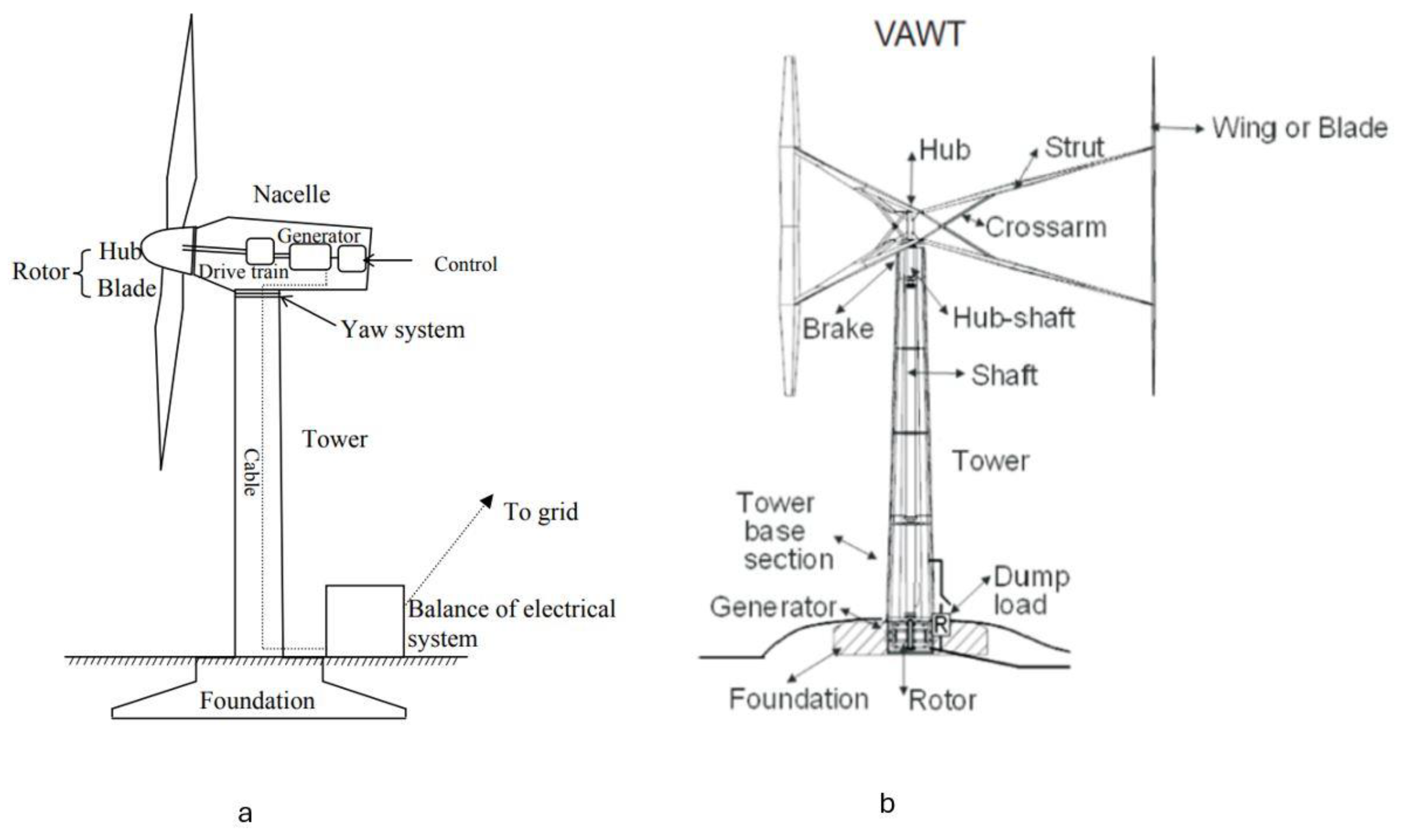
Figure 2.
a) Velocities and b) forces in the rotor plane of the VAWT.
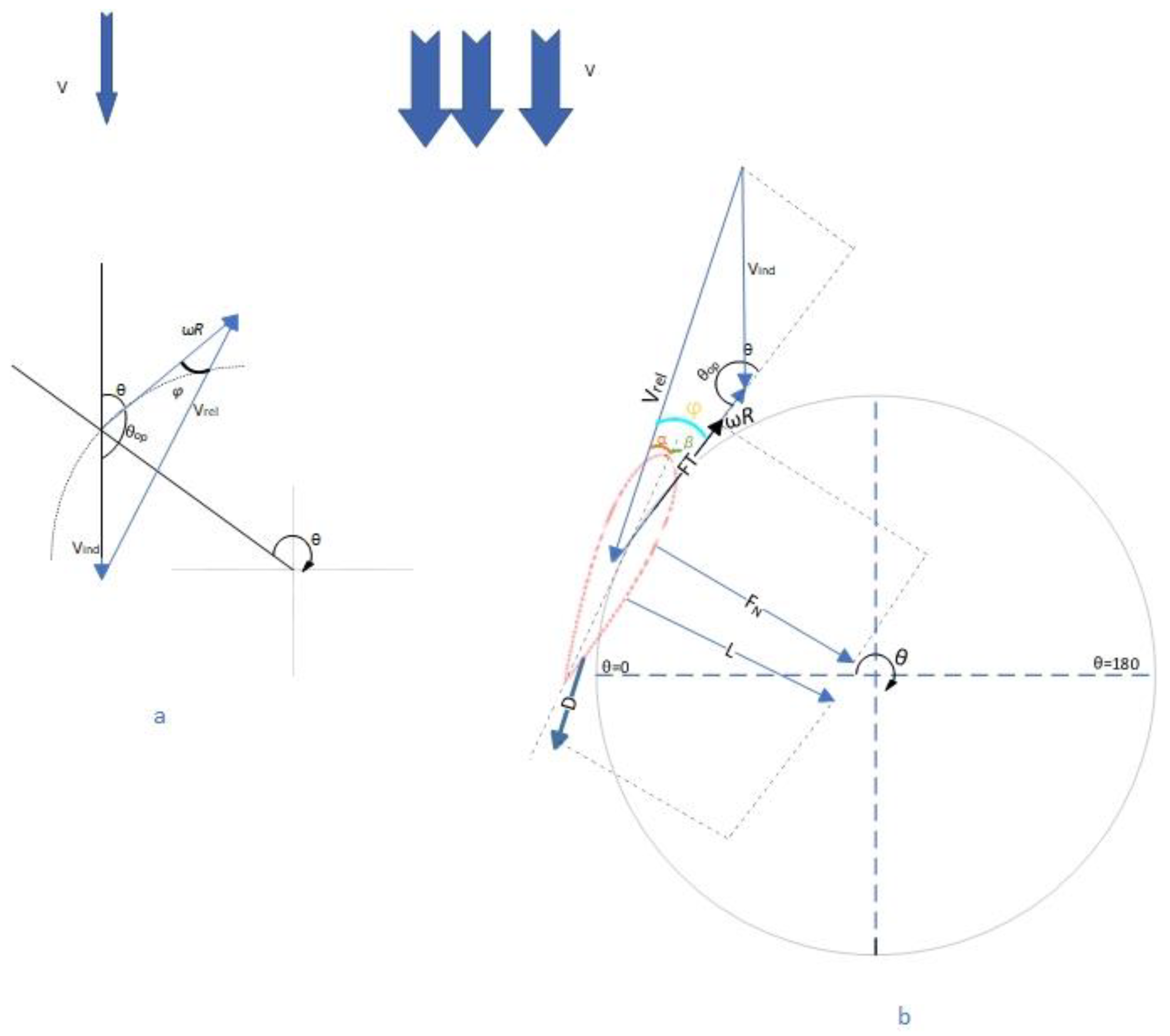
Figure 3.
The derived equations from experimental data from a NACA0018 airfoil in a wind tunnel: a) is the lift and b) is the drag coefficient vs α.
Figure 3.
The derived equations from experimental data from a NACA0018 airfoil in a wind tunnel: a) is the lift and b) is the drag coefficient vs α.

Figure 4.
a. AAWT assemblies and centre of rotation, no tilt applied. b. AAWT assemblies and their dimensions, no tilt applied.
Figure 4.
a. AAWT assemblies and centre of rotation, no tilt applied. b. AAWT assemblies and their dimensions, no tilt applied.
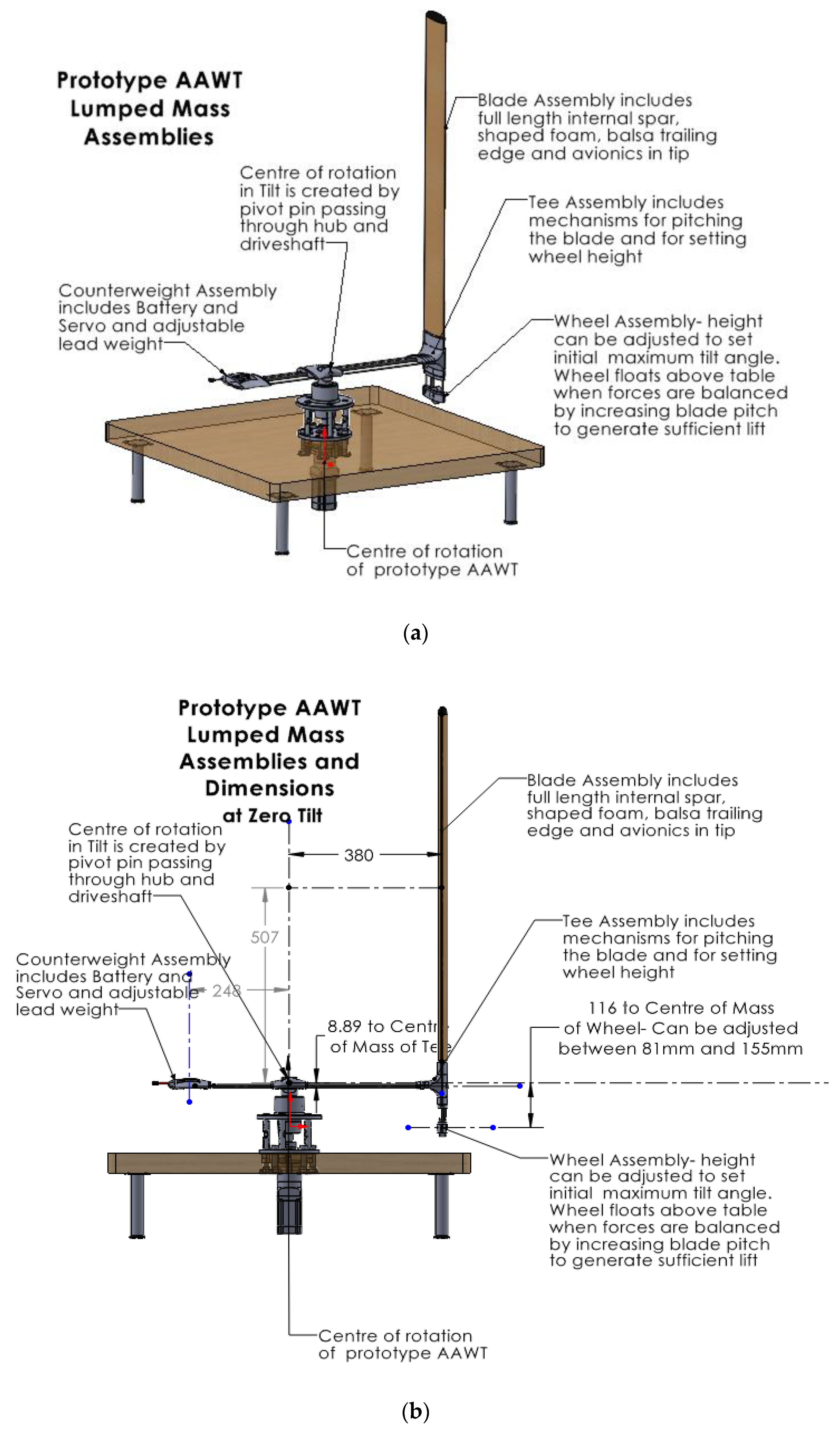
Figure 5.
AAWT Dimensions to forces with applied tilt.
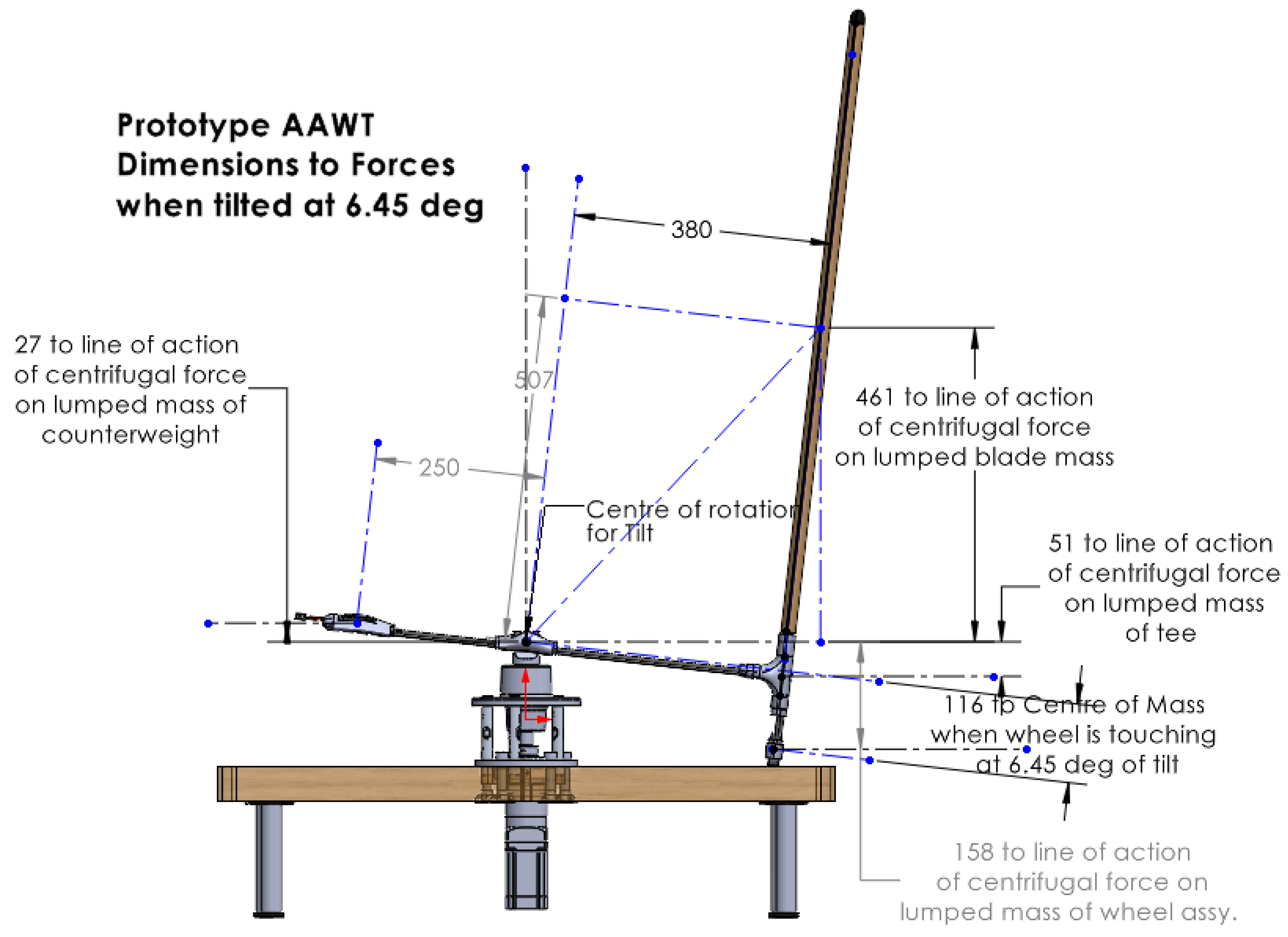
Figure 6.
Lumped mass model of the AAWT assemblies.
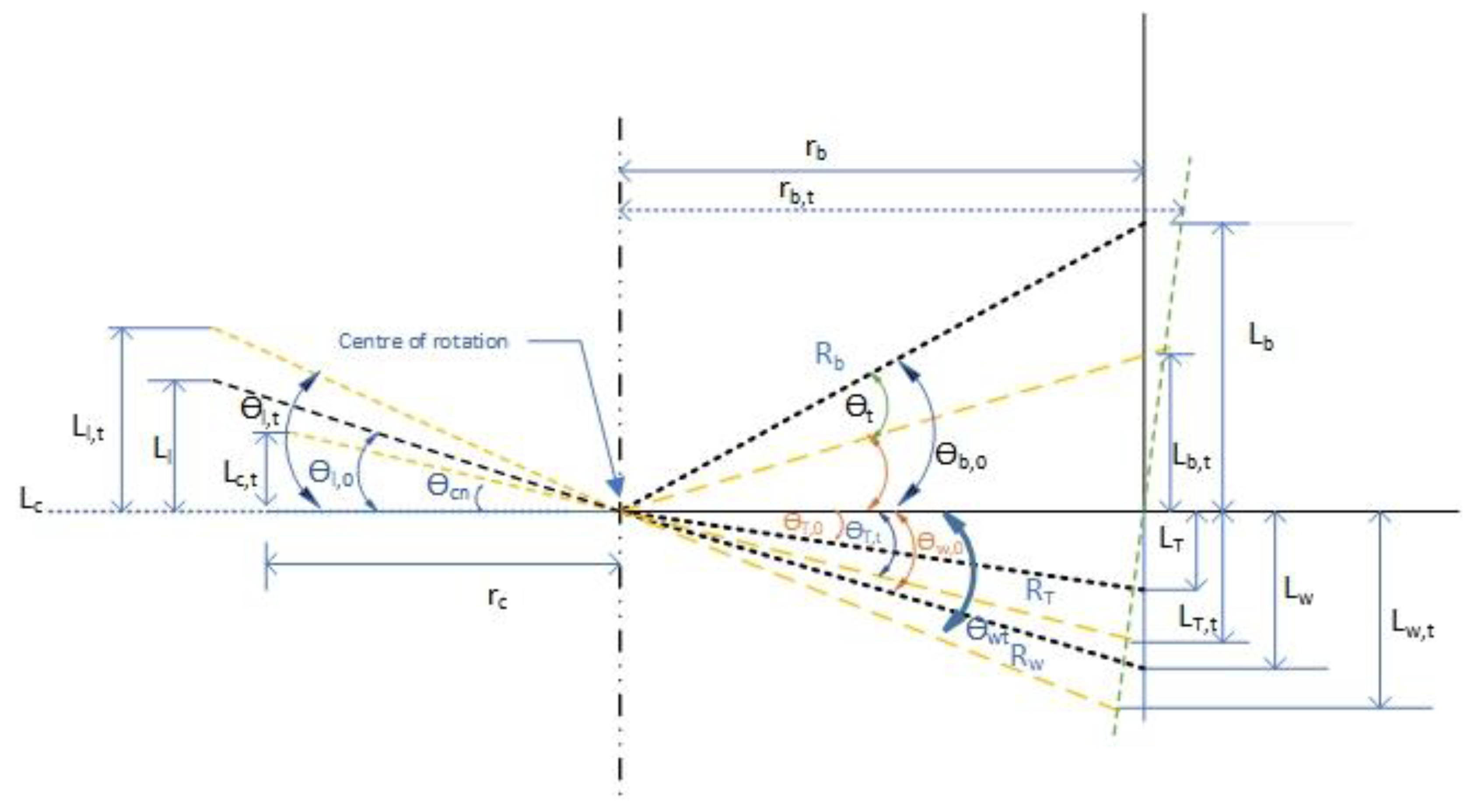
Figure 7.
Flowchart of design methodology procedures.
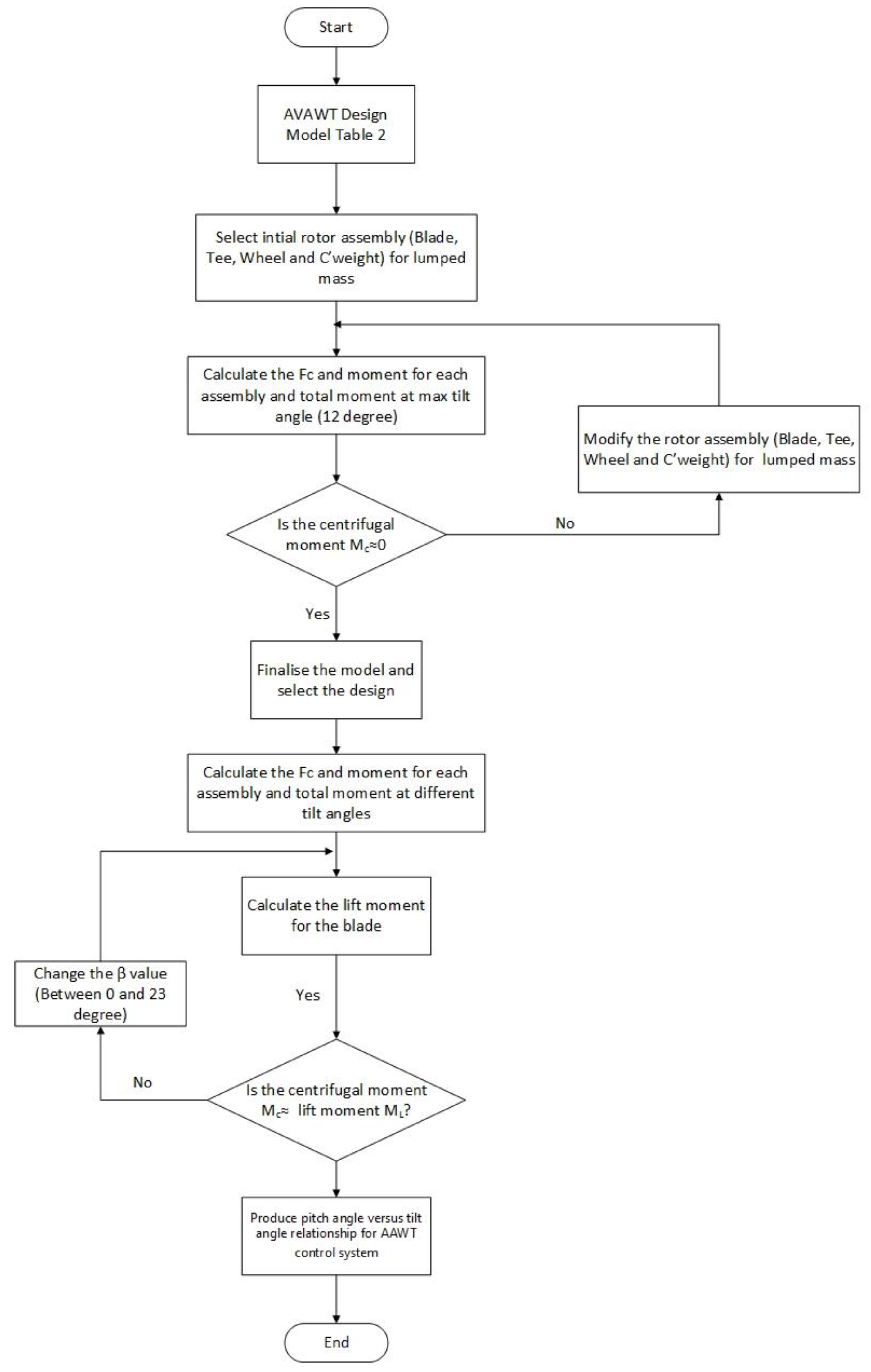
Figure 8.
Revised design to add radius, height and mass to the counterweight.
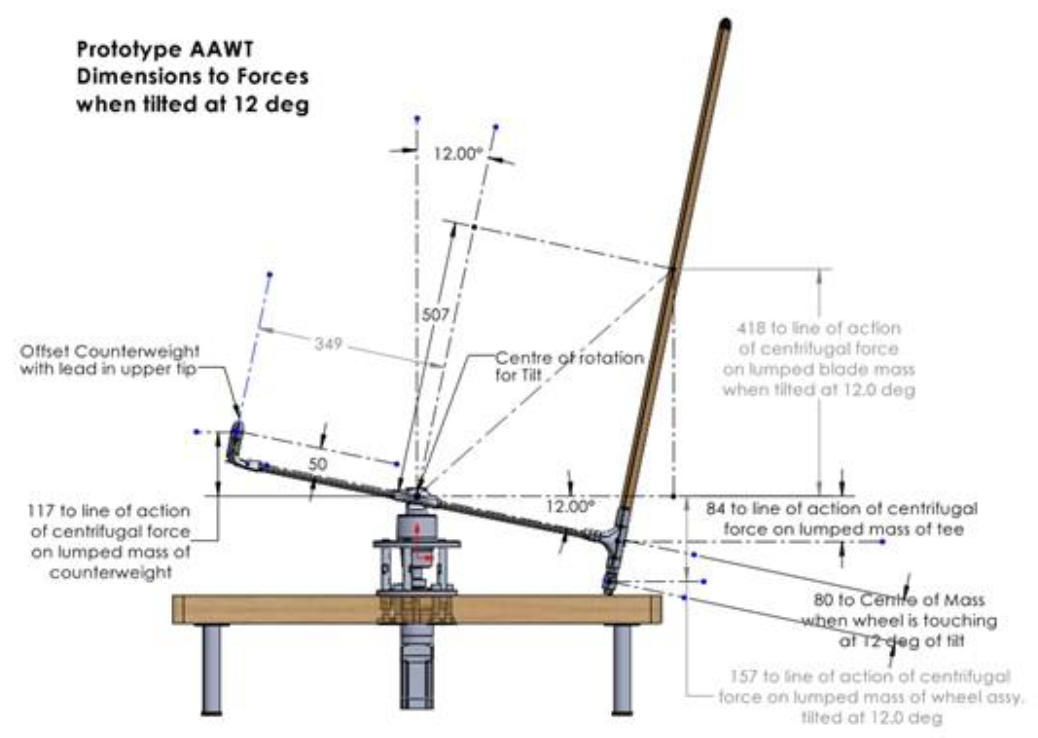
Figure 9.
Moment vs. Tilt Angle of various assemblies.
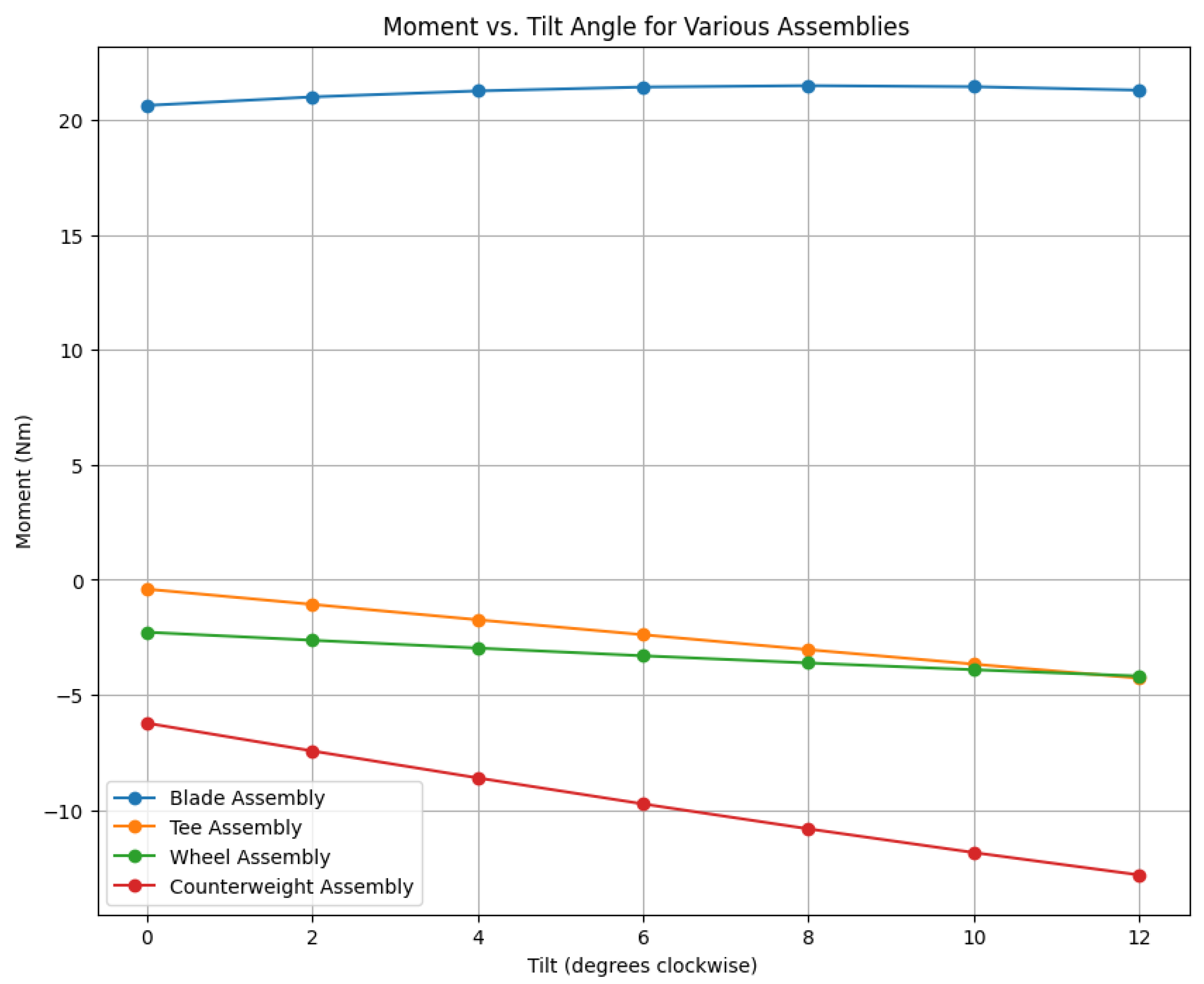
Figure 10.
The relationship between pitch and tilt angles provides the equilibrium of acting forces.
Figure 10.
The relationship between pitch and tilt angles provides the equilibrium of acting forces.
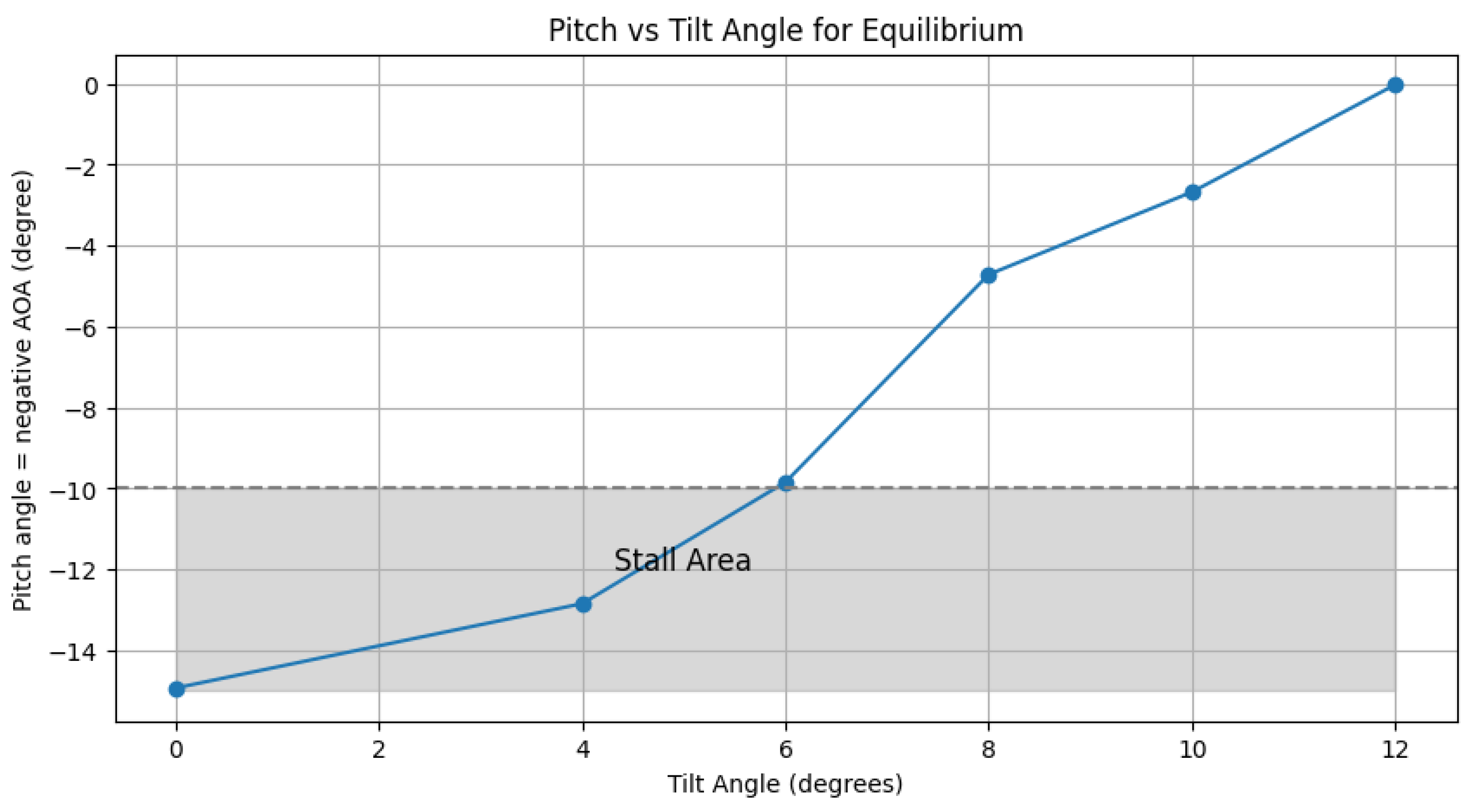

Table 1.
Comparison between the HAWTs and VAWTs.
| Feature | HAWTs | VAWT |
|---|---|---|
| Direction | The rotor shaft is horizontal | The rotor shaft is vertical |
| Airflow disturbance | Less significant compared to VAWTs due to the rotor orientation | High disturbance on the downwind pass |
| Induction factor | Impacts efficiency once | Impacts efficiency twice |
| Aerodynamic efficiency | Better performance - more efficient than VAWTs by about 25%, making them more suitable for large scale [19] | Lower performance due to aerodynamic issues only extracting 30–40% of the kinetic energy in the wind and needing additional power to start the rotation[20] |
| Application | Suitable for open space and stable wind status. | Suitable for turbulent and low wind areas, for example, in urban settings [21] |
| Infrastructure | Need a more substantial foundation but no other support | Need less substantial foundation but additional support such as struts |
| Blade design | More complicated blades - twisted shape and sophisticated profile | Simpler blade design – especially H-rotors |
| Cyclic loading | Lower amplitude cyclic loading | Higher amplitude due to force imbalance through each rotation |
| Market penetration | Higher because of better efficiency and performance | Lower because of structural and efficiency issues |
| Thrust impact on rotor | High impact due to large hub heights and stronger winds | Moderate impact |
| Overturning forces | High - an expensive foundation is needed. Floating foundation for offshore application uneconomic |
Lower for some designs. VAWTs may be more suitable for offshore floating applications |
| Centre of mass | High | Low for the same capacity |
| LCOE (USD/kWh) | 0.027 to 0.074 for onshore applications and 0.09 to 0.191 for offshore applications for 5 MW HAWT [22] |
0.157 to 0.190 for 5 MW VAWT [11] |
Table 2.
Characteristics of the turbine.
| Parameter | value |
|---|---|
| Nominal rotational speed (rpm) | 300 |
| Number of blades | 1 |
| Blade airfoil | NACA0018 |
| Rotor radius [m] | <0.5 |
| Chord length [m] | 0.12 |
| Span [m] | 0.92 |
| Aspect ratio | 7.7 |
| Air density [kg/m3] | 1.2 |
| Minimum manufacturing mass per unit area [kg/cm2] | 1 |
Table 3.
AAWT initial lumped masses and their height and radius.
| Lumped Masses | ||||
| Blade | Tee | Wheel | Counterweight | |
| Mass (grams) | 115 | 136 | 77 | 350 |
| Zero X (mm) | 380 | 380 | 380 | 350 |
| Zero Y (mm) | 507 | 8.9 | 116 | 0 |
| Radius to the centre of mass (mm) | 633.60 | 380.10 | 397.31 | 353.55 |
| Angle to centre of mass (deg) | 53.15 | 1.34 | 16.98 | 0 |
Table 4.
AAWT optimised lumped masses at 12 tilt angles.
| Lumped Mass | ||||
| Blade | Tee | Wheel | Counterweight | |
| Mass (grams) | 115 | 136 | 76 | 301 |
| Zero X (mm) | 380 | 380 | 380 | 349 |
| Zero Y (mm) | 507 | 8.9 | 80 | 50 |
Disclaimer/Publisher’s Note: The statements, opinions and data contained in all publications are solely those of the individual author(s) and contributor(s) and not of MDPI and/or the editor(s). MDPI and/or the editor(s) disclaim responsibility for any injury to people or property resulting from any ideas, methods, instructions or products referred to in the content. |
© 2024 by the authors. Licensee MDPI, Basel, Switzerland. This article is an open access article distributed under the terms and conditions of the Creative Commons Attribution (CC BY) license (http://creativecommons.org/licenses/by/4.0/).
Copyright: This open access article is published under a Creative Commons CC BY 4.0 license, which permit the free download, distribution, and reuse, provided that the author and preprint are cited in any reuse.


