Submitted:
09 October 2024
Posted:
10 October 2024
You are already at the latest version
Abstract
Future manned and deep space missions require an Electrical Power System (EPS) that can deliver high power while overcoming challenges like weight and volume constraints and the harsh environment of space. To supply, store, and transmit power to various satellite subsystems, a variety of DC-DC converters are employed. The design specifications of DC-DC converters for various satellite applications are identified in this article, which also offers a state-of-the-art review of non-isolated, isolated, and integrated topologies. Foreseeing the future of electric propulsion, various electric sources for electric propulsion are contrasted, and converters for electric propulsion are studied. The chosen topologies are compared in terms of practical parameters like reliability, modularity, redundancy, efficiency, and power density. Application-wise comparisons of the topologies are also presented, along with details on how well they work with different kinds of satellites. The article also identifies the areas that are still unexplored for each application. In view of the identified research gaps, a generalized Modular Isolated Interleaved topology of a DC-DC converter is proposed for satellite applications, which is one of the articles’ unique contributions. The MATLAB simulation results of the proposed method, taking Cuk converter as an example for a total power of 5kW are presented. Findings indicate that adding more modules improves the system’s overall reliability, efficiency, and power density by lowering losses, semiconductor current stress, and component size. Such designs are easily adaptable to satellite applications, particularly at high power levels.
Keywords:
aerospace
; DC-DC converters
; deep space missions
; high power electric propulsion
; modular interleaved converters
; satellite power system
1. Introduction
Satellites have been extensively used for applications such as mobile communication, radio and television broadcasting, military intelligence, weather forecasting, and navigation. The launch of satellites Sputnik(83 kg) and Explorer1 (14 kg) by Russia and America respectively marked the beginning of the age of satellites [1,2,3]. Although, small satellites( kg Mass) were initially popular, large satellites started gaining popularity in the 70s and 80s due to their ability to carry more payload and integrate larger solar panels to generate more power. The production and operation cost of large satellites, which is primarily funded by governments and big companies, led the new developers of satellites to look for cost-effective methods to penetrate the market. Thus, the new era of smaller, cheaper, and better satellites began. Such small satellites bring forth cost-effective and time-saving mission possibilities [1,3,4].
Many companies worldwide are investigating the scope of small satellite technologies and are researching on advancement of such satellites. Some initiatives by NASA, ESA, and JAXA are discussed in references [1,5]. The applications of small satellites cover various areas like earth observation, disaster management, space science, microgravity research, earthquake forecast, gravitational field measurements to name a few [1,3]. For many applications, two or more small satellites work together to form constellations or formation flying, which is based on whether an active control is used to maintain a relative position or not [1,4,6]. A summary of evolution, rise, and current challenges in small satellites are discussed in detail in Ref. [3] and a review of the future challenges related to constellations of small satellites is provided in Ref. [7].
Satellites are classified based on their mass into various categories [1,2]. All satellites with a mass are called small satellites. Large satellites are used for applications with lifetime above 10 years and those which are required to carry large payloads like remote sensing payloads, big antennas for communication, etc. Small satellites use miniature components, hence reducing the mass and size of satellites. Such satellites are competing with the large satellites in many applications and their mission time is comparatively smaller than the large satellites [1,8]. The mission’s orbit is another parameter to be considered for satellites. The season and duration of the eclipses experienced by the satellites varies with the type of orbits. The missions can be classified as low earth, Geosynchronous (GEO) earth, Medium earth, or deep space missions. Figure 1 shows these missions and their relative distances from the surface of earth and Figure 2 shows various types of satellites based on their mass and their corresponding power ratings [9,10,11,12,13,14,15]. Low earth orbit (LEO) missions finds application in remote sensing, while GEO orbit is mainly used for communications and broadcasting. Medium Earth Orbit (MEO) satellites are used for navigation, communication, and geodetic/space environment science [9,16].
Large or small, a bus system and a payload system are the two important components of a satellite. The elementary operations of the satellite are performed by the bus while the payload performs the mission-specific tasks. EPS is one of the main and critical subsystems of the bus [17]. Around 33% of the overall mass of satellite is contributed by EPS[18]. The EPS is designed based on the time span of the mission, orbit height from the surface of earth, solar panel sizing requirements, load demand, heaviness of the satellite, radiation effects, efficiency, component count, battery requirement, reliability, redundancy, and fault tolerance level [19,20]. Thus, the overall reduction in size of the satellites requires a smaller EPS with high efficiency. Satellites are classified as a non-serviceable remote autonomous vehicle, thus demanding long life-spans and large end-of-life (EOL) performance parameters. Hence, their design is pivotal in providing the best solution for a given mission ensuring high efficiency and reliability of the overall satellite system [21]. The EPS comprises an energy source in the form of solar array, an energy storage unit mostly, Li-ion battery and a unit for controlling and distributing power, called PCDU [22].
The predominantly used primary power source in satellites is the photovoltaic (PV) cells arranged in arrays. During eclipses or during instances when the solar arrays are unable to achieve the peak power demand, secondary batteries are used to provide the required power. Specific energy, depth of discharge, safety, cost, voltage, shelf-life, and resistance to shock and vibration are some parameters considered when selecting rechargeable batteries for satellites [23]. Generally, Lithium-ion batteries are a good choice for battery storage systems in satellites. A detailed review of various energy storage techniques for small satellites is provided in [5]. The PCDU forms an interface between the PV array and storage systems or loads, by ensuring effective conditioning and transmission of power. The PCDU is designed for specific missions based on the requirements and requires a detailed study to make an optimal choice [21].
A satellite’s propulsion systems are crucial because they enable formation flying, interplanetary paths, collision avoidance, orbital maneuvering, station holding, and orbit transfers [24,25]. Electric Propulsion(EP) has been gaining popularity, especially in small satellites in recent years as they have better fuel efficiency compared to chemical propulsion used in large satellites. Better fuel efficiency is guaranteed by high specific impulse (), which is essentially a gauge of the propellant’s ability to produce thrust efficiently [26,27]. The Space Electric Rocket Test spacecraft equipped with an ion engine, launched in 1964, and the Zond-2 spacecraft used a pulsed plasma thruster, are considered the first illustration of EP [28]. Ref. [29] reviews the recent challenges and solutions related to space electric propulsion. Currently, over 1000 small satellites are active in space. These small satellites are mostly confined to the LEO orbits as they do not possess sufficient for moving past earth orbits. A system that can raise the orbit from LEO to MEO to GEO and beyond would be more cost-effective than directly launching the satellites to orbits farther than LEO. The potential of an EP system to raise orbits is predominantly determined by the duration it can last and the amount of thrust it can provide. Despite its high fuel efficiency, EPs face a variety of challenges. One of the main challenges is the time taken to reach high thrust, which limits their use to certain applications only. One solution is the use of high-power systems improves the time taken to reach high thrust, providing more opportunities for timely orbit changes and interplanetary missions. However, achieving high power without increasing the overall mass or cost is another challenge. Thus, researchers around the world are focusing on enhancing the EP systems to improve the small satellites’ mission ranges [24]. Ref. [30] compares various EP systems and Ref. [31] compares EPs for mini/microsatellites.
High efficiency is necessary for satellite applications, as the weight that can be launched into space is crucial. Transmitting power in satellites at a high voltage (HV) and low current is an excellent way to reduce weight [34]. In this context, distributing power as DC is a reliable option leading to simpler equipment and improved efficiency [35]. However, it demands a wide variety of DC-DC converters. Thanks to the recent development in power electronics which provides a variety of DC-DC converter topologies to choose from. Nevertheless, choosing the best topology for a particular application in satellites is a challenging task as it is decided by the type of the satellite and orbit, duration, and power requirement for the mission. Thus, it is important to compare the various topologies and specify their merits and demerits for various types of missions. Figure 3 shows the various applications of DC-DC converters in satellites, and Table 1 compares the major performance indicators for a few applications of DC-DC converters at high-power levels to show their difference with respect to satellite applications. Existing review articles comparing DC-DC converters for satellite applications are provided in Table 2. Ref. [32] compares Boost-based non-isolated DC-DC converter topologies for satellite MPPT application. However, the study does not consider other non-isolated or isolated topologies or other applications. M.Yaqoob et.al. [33] provides a detailed study on small satellite microgrids where the authors review DC-DC converter topologies, solar arrays, and battery technologies for satellites. However, the scope of the study is limited only to small satellites, especially nano-satellites, and does not discuss electric propulsion for satellites. These studies are either limited to certain applications or types of satellite and do not compare the topologies based on the practical performance indicators as stated in Table 1. Moreover, these articles do not offer any novel ideas for enhancing the current system—rather, they only evaluate the existing literature.
This review article provides an in-depth review of DC-DC topologies for various satellite applications. The scope of the review is not limited to small satellites or earth-orbiting satellites but also considers large satellites, interplanetary, and deep space missions. The article spans a wide range of applications of DC-DC converters for satellites. Different from the existing literature, the topologies are compared using various practical parameters and applications. This paper also makes a distinct contribution by proposing a generalized Modular Isolated Interleaved DC-DC converter topology, which helps improve the reliability, power density, and efficiency of the existing system. The simulation results of the proposed method, taking Cuk converter as an example are presented. The important contributions of the article are mentioned below, and the graphical abstract is provided in Figure 4.
- Identify the design requirements for DC-DC converters and provide an up-to-date review of various isolated and non-isolated topologies for satellite applications.
- Analyze the scope of electric propulsion for future manned and deep space missions and review DC-DC converters for electric propulsion applications.
- Performance evaluation for the considered topologies in terms of practical parameters (like reliability, power density, size, efficiency, redundancy, modularity, and performance in harsh environmental conditions) and identify the best topology for a considered application in satellites.
- Classification of the converters based on various applications and types of satellites.
- A novel generalized Modular Isolated Interleaved topology is presented in which each module works at a small fraction of the total rated power. The topology provides improved reliability, efficiency, and reduced weight. The MATLAB simulation results of the converter are provided for a rated power of , taking Cuk converter as an example.
The article is expected to be a guide for researchers and space industries for selecting the best topology, given a satellite application. The remainder of this paper is arranged as follows: section II discusses the various electrical subsystems in satellites, section III focuses on the applications of DC-DC converters in satellites and the design constraints for such converters for satellite applications. Section IV reviews the various isolated, non-isolated, and integrated topologies of DC-DC converters and their comparison is provided in section V. Section VI discusses the generalized Modular Isolated Interleaved topology. Section VII discusses the future directions in the area and provides insight into the current and future deep space missions. Section VIII concludes the paper.
2. Electrical Subsystems in Satellites
2.1. Unregulated and Regulated Bus System for Satellite EPS and EPS Architecture
Satellite EPS can be classified as: unregulated bus and regulated bus system. Figure 5a,b shows the two types of bus systems [36]. Various integrated topologies of three-port converters which integrate the unidirectional and bidirectional converters into a single unit are also found in the literature. This provides reduced component count, conversion stage, reduced cost, and increased reliability. A comparison of conventional two-port converters and integrated three-port converters for satellite EPS is discussed in [37]. The power transfer from the source to the batteries and loads uses either Direct Energy Transfer (DET) or Maximum Power Point Tracking (MPPT) architectures [33,38,39,40,41,42,43,44,45,46]. Figure 5c,d shows the architecture of a simple EPS[47,48]. For distributing power, two basic design approaches are used: distributed power and decentralized power architecture [49]. Figure 5e shows the schematic of the distributed architecture and two types of decentralized approaches, as shown in Figure 5f,g [49].
2.2. Electrical Propulsion systems
EP systems for satellite applications convert electrical potential energy to kinetic energy to accelerate a propellant. In general, the transition can be done electrostatically, electrothermally, or electromagnetically based on the method used to accelerate the propellant[24,50]. Figure 6 shows some widely used electrical propulsion systems along with their approximate power requirements. For space propulsion, the efficiency is measured in terms of fuel consumption to find an important performance measure called specific impulse. The equation representing the specific impulse of a thruster is shown below:
where, I represents the total impulse of the thruster throughout its lifetime, represents propulsive mass and g represents the gravitational on the surface of the earth. Equation 1 illustrates that the higher the , the lower is the propellant required to produce the given impulse. Since EP has a high , it can achieve larger final velocity and total impulse, as long as the thruster is fired for a sufficient amount of time. Another parameter that determines the superiority of a propulsion system is the thrust per unit input power given by:
Thus, the amount of on-board power that is available limits the thrust level.
Electrical thrusters are low-thrust devices that operate for extended periods because they produce a high specific impulse [28,51]. In contrast to chemical propulsion, an external source like PV panels, batteries, Radioisotope Thermoelectric Generator (RTG), or a nuclear reactor delivers energy in EP systems. While solar energy is preferred for earth orbit missions, nuclear energy is the preferred choice for deep space and interplanetary missions [28]. The scope of solar-powered EP which is limited by the solar irradiation at different points in space is schematically represented in Figure 6 which also shows some of the past, present, and future Solar EP missions along with their power levels [52]. The electronic circuitry and the related power levels are the two main contributors to determining the appropriate propulsion system for a mission. Thus, the power processing unit (PPU) for EP must be capable of providing high-power levels at high efficiency. Power electronic converters have an important role to play in this regard. Various DC-DC conversions are done in the PPU to boost voltage levels while achieving high power.
In short, DC-DC converters are an important part of satellites. Improving their performance is thus vital. They may be isolated/non-isolated or unidirectional/ bidirectional. A variety of such converters are found in the literature for applications in satellites. Recently, various integrated topologies (isolated and non-isolated) are also proposed for satellite applications. The next section discusses the major utilization of DC-DC converters in satellites and provides the important design constraints for these converters for use in satellites.
3. Features of DC-DC Converters for Satellite Applications
The low-voltage (LV) bus in the satellite EPS supplies the LV emergency batteries and other storage components, while the high-voltage (HV) bus supplies the necessary power for electrical actuators and other satellite equipment. The active interface that connects the LVDC and HVDC buses is a DC-DC converter that ensures reliable and efficient transmission of power. The converter regulates the output voltage to the desired value with good power quality. Depending on the application, isolation and voltage regulation may be needed at various phases of power conversion. Galvanic isolated DC-DC converters are also necessary for connecting PV arrays. The PPU of the EP also requires high-power DC-DC converters as outlined in the preceding part. Thus, with regard to applications, DC-DC converters find the following applications in satellites [53]:
- maximum power point tracking (MPPT).
- management of battery charging/discharging.
- supply power to the payloads and other satellite subsystems.
- electric propulsion.
- voltage conversion.
- voltage regulation.
EPS is a critical subsystem of a satellite, as an interruption of power is undesirable for its operation. This demands reliable and efficient PCDU. Also, in the era of miniaturization of satellites, a converter capable of providing high power without increasing the mass or volume of the EPS is highly relevant. In power electronics, improved power density is achieved at high switching frequencies, as it leads to reduced dimensions of magnetics. Nevertheless, high switching frequency leads to increased switching losses, resulting in larger heat sink requirements. Thus, a trade-off exists between power density and heat dissipation requirements. Additionally, considering the harsh and stringent environmental conditions prevailing in space, the converter components must be carefully chosen to provide good performance under such conditions. Thus, summing up, the following design requirements are desirable for DC-DC converters in satellite applications [54,55]:
- high power density.
- high efficiency.
- minimum increase in volume / weight / heat management.
- reliability.
- modularity.
- good performance in harsh environment like large temperature and pressure variations, mechanical vibrations etc.
- high switching frequency to minimize the size of magnetic components.
- lower Electromagnetic Interference (EMI).
These features are also schematically represented in Figure 7. Several topologies are mentioned in the literature for various applications. However, they cannot be directly adopted for satellite applications due to the strict design requirements in space. The following section provides a detailed review of such topologies.
4. Review of DC-DC Converters for Satellites
A review of various DC-DC converters for satellite applications is provided in this section. For the review, the topologies are classed into Non-isolated and Isolated. Various integrated converters and topologies for high-power EP are also compared.
4.1. Non-Isolated Topologies
This section reviews the various non-isolated DC-DC converters for satellite applications. The classification is shown in Figure 8. The non-isolated converters provide benefits such as design simplicity, reliability, and reduced component count [56]. Nevertheless, they suffer from problems such as lack of controllability and increased losses due to extreme duty cycle operation [57]. They find applications in small satellites for converting and regulating power. A detailed review of such converters is provided by M.Yaqoob et al. in [33].
4.1.1. Buck-Derived Topologies
A topology based on buck converters was suggested by the authors in [58] for interfacing storage batteries with solar panels for EPS in nano-satellites. Two coupled inductors at the output stage reduce the current ripple without compromising the efficiency. It also reduced the component count of the EPS. The converter was simulated using MATLAB/Simulink, and the output confirms its functionality under various source and load scenarios. Ref. [59] proposed a load-side redundant buck converter for nano-satellites which comprises two half-bridge modules with a shared inductor and a fuse providing over-current protection. The redundant module is operative only under faulty conditions. Although the topology provides a fault diagnosis capability, its applicability for small satellites needs to be evaluated considering the volume and weight restrictions for small satellites. Figure 9 shows the various Buck-derived topologies of DC-DC converters.
4.1.2. Boost-Derived Topologies
High-power DC-DC conversion with good efficiency and lesser cost can be achieved by a parallel-connected structure of PV [60]. In satellite applications, a Boost converter is used for implementing MPPT and connects the LV PV to the HV bus. Various Boost-based topologies for space applications has been compared and analyzed by Garcia et al. [32]. Based on the operating voltage range, power handling capability, and output impedance of the solar array, the best topology was selected. Among these topologies, the conventional boost converter is highly reliable on account of its reduced device count. Nevertheless, the losses associated with the converter are high due to its reverse recovery diode. The switch near ground boost topology has a simple driving circuit and transfers energy directly from input to output. However, the topology has high mass [32]. The topology was modified and proposed in Ref. [61] which is bidirectional with reduced mass and volume. The topology was specifically designed for high-power applications in LEO satellites. The two-inductor boost topology proposed in [62] provides advantages like continuous input and output currents. However, the topology has two inductors and has poor dynamic response [32].
The ripple cancellation-based boost converter proposed in [63] has an additional branch to cancel ripple in input current. However, the number of components in the converter increases due to the additional branch added [32]. The common damping 2-inductor Boost converter was derived from the two-inductor Boost converter by the addition of a damping network, showing improved bandwidth and complicated power structure. However, the converter leads to increased losses in the magnetic components [32]. Interleaving boost converters reduce the component count, provide a good transient response, and reduce the output current ripple greatly[64]. A Boost-based multiple-input, multiple-output interleaved topology was proposed in [65] for spacecraft applications. The converter implements MPPT, and provides a fixed voltage at the output and battery control. Figure 10 shows the various Boost-derived topologies of DC-DC converters.
4.1.3. Buck Boost-Derived Topologies
The Buck-Boost-based converters can act in Buck or Boost mode, thus providing bidirectional capabilities controlling the charging and discharging of EPS batteries, based on the measured SOC [66]. Authors in Ref. [44] proposed a Buck-Boost regulator(B2R) for application in regulated or unregulated bus systems for satellite EPS. The topology provides good performance and ensures that the bus voltage is following the maximum power point PV voltage. Later, this topology was modified to Buck-Buck-Boost regulator(B3R) in [67], which reuses passive components to reduce mass and cost. Finally, in [68], an improved Weinberg topology which is bidirectional was proposed. The topology is a combination of the Weinberg topology and the buck topology placed side by side, leading to high power density, efficiency, and a non-complex structure. In addition, it also provides bidirectional power flow capabilities and works in buck or step down and boost or step up modes. Figure 11 shows the various Buck-Boost derived topologies of DC-DC converters. A comparison of all the non-isolated topologies discussed above is provided in Table 3.
4.2. Isolated Topologies
The different isolated converters for satellite EPS are discussed in this section. DC-DC converters with isolated topologies are the result of galvanic isolation being provided between the converter’s input and output in order to achieve effective power transfer with minimal noise and electromagnetic interference. One can use a coupled inductor or a transformer to achieve electrical isolation. The classification of Isolated converters for satellites is shown in Figure 12.
4.2.1. Flyback and Forward Converters
A. Connaughton et al. in [69] proposed a soft switched flyback converter with complete control on secondary side for satellite application. The flyback, forward and flyback-forward topologies reduces the component count but have a very low value of efficiency [70]. Ref. [71] proposed an isolated multiple-output forward converter with a magnetic feedback. The converter has good reliability, as the magnetic feedback and controllers do not get effected by the environmental conditions in space [72]. Another topology of multiple-output converter based on flyback converter is proposed in [73]. The topology provides advantages like good load and line regulation and high efficiency. However, the converters based on flyback or forward converter shows low value of efficiency and thus they find use in low-power applications.
4.2.2. Full Bridge Converter
The use of a PWM Full-bridge topology has been investigated for satellite applications in [74]. Full-Bridge converters are quite popular for various applications due to their features like good transformer core utilization, simple circuit, low-voltage stress on switches, and good power handling capacity [75]. The conventional Full-bridge converter is a well-known topology and operates over a wide output range with good efficiency. Nonetheless, the output diodes’ speed determines the frequency of switching. Also, the converter is prone to shoot-through problems. Ref. [74] compared the performance of the PWM Full-bride converter with the phase shifted PWM converter. This converter has inherent soft switching capability and high efficiency. However, it also faces similar problems of switching frequency and shoot through problem. Comparing the phase-shifted Full-bridge with the PWM Full-bridge converter for applications in satellites, it offers higher efficiency. Nevertheless, its control strategy is complex as compared to the PWM Full-bridge converter. The circuit topology of a basic Full-bridge converter is shown in Figure 13.
4.2.3. Current-Fed Weinberg Converter
The benefits of using the current fed Weinberg topology were investigated in [74] for satellite applications. As compared to the Full-bridge converter, this converter is shoot-through tolerant and the input voltage spans a broad range without compromising the efficiency. However, the circuit is more appropriate for low voltages as it leads to high stress on the semiconductor devices. Ref. [76] proposed a non-isolated Weinberg converter for application as a battery discharge regulator in satellites. The authors performed a small signal analysis of the converter demonstrating faster dynamic response compared to conventional PWM regulators. The circuit topology is shown in Figure 14.
4.2.4. Current-Fed Cascaded Buck and Full Bridge Converter
A current-fed converter based on cascaded Buck and Full-bridge topology was investigated in [74]. The converter is shoot-through tolerant and lower wide output voltage range. However, high component count, limitation in operating frequency, and lower efficiency due to additional switching stage are the disadvantages of the topology. Figure 15 shows the circuit topology of a current-fed cascaded Buck and Full-bridge converter.
4.2.5. Resonant Converters
Resonant converters like isolated LLC and LCC resonant DC-DC converters and series resonant converters that use resonant networks to obtain switching at zero voltage or current has been proposed for high-voltage applications in [74,77]. In terms of efficiency, the resonant LLC converter is superior and in terms of input or output voltage range, the LCC converter is superior. Although they provide high-efficiency conversion, reduced mass due to increased switching frequency, and high power density, the requirement of complex control techniques limits them to low-power applications [74]. Figure 16 shows the circuit of a basic resonant LLC converter.
4.2.6. Dual Active Bridge Converter
The Dual Active Bridge(DAB) topology is highly accepted among researchers over the past couple of years for high-power density aerospace applications [78]. They exhibit high performance and efficiency with inherent galvanic isolation and soft-switching capabilities. They are well-suited to handle high power, have a simple structure, and high transformer utilization factor [75,79]. Several works have been proposed in the literature based on DAB converters for high-power applications. Ref. [35] performed the modeling, design, implementation, and performance evaluation of the DAB converter using SiC switches for aircraft electrical power networks. [80] provides a comparison of isolated bidirectional converters using Wide BandGap (WBG) devices for more electrical aircraft (MEA). The study compares conventional DAB, Active Neutral Point Clamped (ANPC), Neutral Point Clamped (NPC) and Input-Series Output-Parallel (ISOP) converters to understand the advantages of using WBG for electrical aircraft. Figure 17a–d and Figure 18a show the above four types of DAB topologies.
A comparative study was conducted to analyze the converters based on their efficiency, heat management, power density, and EMI. The conclusion of the comparison is shown in Figure 19[80]. The figure illustrates the superiority of the ANPC type concerning efficiency, heat regulation, and power density. The ISOP and conventional DAB converters exhibit comparable results with high efficiency. Although the NPC converter provides the best EMI performance along with the ANPC type, it shows poor performance in terms of the other three parameters. The design of a conventional DAB converter for space applications is discussed in [81].
About the modulation strategy used, single phase shift modulation is the most widely used method in DAB converters due to its simplicity [82,83]. Advanced modulation methods like extended or dual phase shift, triangular or trapezoidal current modulation were also proposed in [54,84]. Ref. [85] proposed an interleaved parallel DAB topology with a coupled inductor for MEA and compared the performance of the converter with three types of modulation methods viz; single, extended phase shift, and PWM plus single phase shift. The topology is shown in Figure 18b. According to the study, a single phase shift combined with PWM can handle at least two times the power as a conventional DAB, while an extended phase shift can lower current stress.
4.2.7. Active-Bridge Active-Clamp Converter
Another topology of DC-DC converter for aerospace applications with galvanic isolation is the Active Bridge Active Clamp (ABAC) topology [77] as shown in Figure 20. It is similar in operating behavior to the DAB converter. However, it provides a current fed LV stage. Ref. [54] compared various parameters of the ABAC converter and the DAB converter. A constant current on the DC side due to interleaved inductors with reduced filter requirements on the LV side, makes the ABAC converter superior to the DAB converter. Nevertheless, a capacitor filter is required to control the ripple resulting from asymmetries in the topology and harmonics in the load current. A comparison of the weight and volume of the ABAC and DAB converters is also provided in [54]. In DAB converters, the weight is mainly contributed by capacitors while in ABAC converters, a major part of their weight and volume is contributed by inductors. Nonetheless, the inductance values associated with ABAC converters are relatively low, leading to reduced weight and volume of the converter. This tendency becomes more evident at high powers, making these converters a strong candidate for high-power applications. Thus, the ABAC converter is a good replacement for the DAB converter without loss of efficiency and with improved power density.
4.2.8. Active Clamp Forward Converter
N. Lee et al. in Ref. [86] proposed an improved active-clamp forward (ACF) converter for developing a reliable, light-weight, and EMI-compatible EPS for satellites. Although the ACF converter has a simple structure, a lesser number of components, and clamping properties, its oscillating input current, high value, and voltage stress across switches demand a higher filter size and make it a poor choice, especially for high input voltage applications. These problems are overcome using the improved ACF proposed in [86] which used two series connected switches to decrease semiconductor stresses. Moreover, during turn-off, a delay is provided to avoid the imbalance in switch voltage stress. Experimental results also revealed a lower ripple in the current on the input side. Thus, the improved ACF topology is a strong contender for satellites requiring high power density. Figure 21 shows the improved ACF topology proposed in [86]. A comparison of isolated DC-DC converters discussed above is described in Table 4.
4.3. Integrated Topologies
This section reviews the various integrated multi-port converter topologies for application in satellites. In integrated multi-port topologies, switches and storage elements are shared during various operating modes, leading to reduced component count and conversion stages. They are compact and have improved reliability as compared to several independent converters performing the same task. The classification of integrated DC-DC topologies is shown in Figure 22.
4.3.1. Three-Port Modified Half Bridge Converter
Ref. [37] proposed a three-port DC-DC converter(TPC) with one input port from the solar array, one bidirectional port from the battery, and an output port that is isolated. The topology attains zero voltage switching for all semiconductors and reduces on-state losses by adopting synchronous rectification on the secondary side. A generalized method of modeling a three-port converter is also provided in the paper. However, the converter employs a complex control technique. Figure 23 shows the three-port modified half bridge converter.
4.3.2. Non-isolated PWM-Three-Port Converter
In TPCs, the duty cycle during each cycle of the pulse is shared by many input ports. This effectively reduces the duty cycle of individual ports, leading to increased RMS currents and reduced efficiency [87,88]. Moreover, problems due to unshared ground and complexity of control circuits also exist [36]. To overcome such challenges, [89] proposed a novel non-isolated PWM-TPC using uni- and a bidirectional PWM converter as shown in Figure 24. The converter is simple, avoids unshared ground issues, has higher effective duty cycles, and reduces inductor size. The size of passive elements in the converter decreased by about 19% when compared to the conventional non-isolated TPC, according to a comparison of the converter’s volume with that of the conventional system with two different PWM converters.
4.3.3. Two Switch Forward with Integrated Buck Converter
In [17], J.E.Park et al. provide the heritage design properties of DC-DC converters for satellites in alignment with the International Satellite Electronics Design Standards [90]. According to the study, the following design characteristics must be met by a DC-DC converter designed for satellite EPS:
- Non-Leg structure: The converter should have a conservative design where a fault at a node should not interrupt the functioning of the entire system, thus ensuring an extended life for the satellite. A non-leg structure is proposed in [90] as a potential solution in this regard.
- PWM Controlled: To be in alignment with the strict EMI and EMC regulations in space and considering the variation of passive components in space, pulse-frequency modulation control is not recommended for DC-DC converters for satellites. Thus, PWM control is the proposed method of control[90].
- To create a DC-DC converter architecture compliant with the aforementioned requirements, the authors in Ref. [17] developed the topology shown in Figure 25. A buck converter and a forward converter are combined, thus eliminating a diode and a switch. As a result, the topology’s cost, mass, and volume decreases. Furthermore, ZVS is obtained for a few switches, increasing the converters’ efficiency. The above-mentioned integrated topologies are compared in Table 5.
4.4. High Power Electric Propulsion
The electric propulsion system accounts for about of the overall weight of a satellite [91]. They are classified as low(), moderate(), or high power() levels. Considering the solar power on modern satellites, and the commercial and deep space missions, the moderate power level will rely on electric propulsion in the future [92]. The Hall effect thruster is widely used to achieve a high ratio between thrust and power and efficiency for applications over [29,92,93,94]. A more dominant type of electric thruster at moderate power levels is the moderate-power gridded ion thruster [95,96,97]. NASA’s Artemis Lunar exploration program which is focused on human explorations to Mars necessitates a high-power EP based on solar power[98,99,100].
Ref. [101] studied a 6kW hall-effect thruster system developed by JAXA with a 4 to 34 A and 175 to 800 V output current and voltage range, respectively. Four 1.5 kW converters with digital control that can flip to parallel or series connections were used to implement it. The converters exhibit ZVS and showed an efficiency of 96% at 300 V [102,103]. LLC resonant topologies are typically employed in limited output voltage-controlled operating conditions. They employ soft-switching technique to improve efficiency [104]. Four converters with high efficiency for broader values of output voltage were proposed by the authors in [101]. The number of components is decreased through the use of digital control. Future research, according to the authors, should look into balancing the current between the converters operating parallelly as well as how their characteristics vary. Subsequently, [105] presents a comparison of different control algorithms that can impact the operational life and cost of a spacecraft in the future.
The authors in Ref. [106] developed a modular PPU for a 40cm Ion Engine. The design was based on a phase shift modulated/ PWM DAB converter which showed high power density and efficiency. Another work based on the DAB proposed a combined dual modulation scheme for an all-electric propulsion system. The converter provided advantages like modularity, good voltage gain, and power density inherent to the DAB converter[107]. A lower RMS or peak current under ZVS is another benefit of the combined dual modulation scheme that helps the AEPS system to operate with high efficiency and good transient response throughout its whole operating range. It performs well against EMI noise as well. The control scheme was validated using a DAB converter [108].
A two-stage DC-DC converter comprising a four-switch interleaved Buck-Boost converter and an LLC resonant converter was proposed in [109] for high-power PPU in an Ion propulsion system. The interleaving method used in the first stage reduced the magnitude of the magnetic components and the soft-switched LLC resonant converter improved efficiency. Furthermore, the utilization of transformer leakage inductance as resonant inductance offered a high power density. After testing, a prototype demonstrated good efficiency and power density performance. The first stage of the converter is shown in Figure 26 and a comparison of various topologies for EP are provided in Table 6.
5. Comparative Analysis of Various Topologies
This section provides the performance analysis and comparison of the various DC-DC converter topologies for application in satellites. The converters’ switching frequency can be raised to minimize filter size and boost power density while still meeting design specifications. Nevertheless, a larger switching frequency leads to increased switching losses and demands higher heat dissipation requirements. This also leads to reduced efficiency. Therefore, a trade-off exists between power density, efficiency, and heat dissipation requirement in the converter [110]. Galvanic isolation is also an important requirement of satellite converters considering safety reasons and to prevent fault propagation within the satellite subsystems [110]. Regarding efficiency, high-efficiency operation reduces fuel consumption and increases the life of the satellite. Moreover, it leads to lower heat dissipation requirements, lower cost, and improved reliability and power density. Semiconductor switches account for the majority of the losses in power converters. In high-power satellite applications, parallel connection of several modules called modularization is done to improve the voltage and current capacities [80]. It enhances the performance by increasing the redundancy, ease of maintenance, scalability, and fault ride through capabilities of the converter [111]. Figure 27 shows the various performance indicators for DC-DC converters for satellite applications.
The most important consideration for satellite applications is reliability, which must be weighed against other considerations like converter cost, efficiency, and power density. The lower the component count, the greater the reliability. Switching devices and their control circuits are considered the parts most prone to failure in a power converter. Capacitors are the next, as they are prone to failure, especially during high temperature applications. Although they are troublesome and seriously question the reliability, they are unavoidable. To improve the performance, space grade components are used, although at an increased cost [112]. Redundancy and modularity are two important means of improving reliability. The comparison of various non-isolated, isolated, and integrated topologies in terms of the performance parameter mentioned in Figure 27 is shown in Table 7, Table 8, and Table 9, respectively. The performance comparison of high-power DC-DC converters for EP is shown in Table 10. A comparison of the topologies based on their application in satellites and the types of satellites that they can be used for is provided in Table 11.
6. Modular Interleaved Cuk Converter
In view of the presented review on DC-DC converter topologies for satellite applications, a generalized Modular Isolated Interleaved topology is presented in this section. Reliability being a critical performance parameter, a modular design where converters are connected in parallel is proposed, which helps improve reliability. Paralleling DC-DC converters provide advantages like low semiconductor stresses, improved reliability, ease of maintenance and repair, and improved thermal management to name a few [113]. The parallel connected modules are also interleaved, as interleaving provides a reliable converter with a lower value of output current ripple, reduced switch current stress, and improved efficiency [114,115,116,117,118,119]. In interleaving, multiple module switches are turned ON/OFF with a time delay of such that,
where n is the number of modules connected in parallel. The input current and output current for each module is given by
where and are the effective input and output currents, respectively. According to [115], for an interleaved converter with N modules, the relationship between total output current ripple, and the output current ripple for each phase, is given by
where is the cancellation factor which lies between 0 and 1 and D is the duty ratio. The increased frequency of output current ripple due to interleaving leads to reduced size of the magnetics and lowers the converters’ total dimensions. In parallel connected converters, it is important to ensure equal sharing of power among the modules, and this is achieved in the proposed topology by using appropriate control techniques. The control strategy for IPOP systems as proposed in [111] is employed for ensuring equal current sharing. Such modular designs can be easily incorporated into satellite applications, especially at high-power. The control strategy and a generalized model of the suggested method are displayed in Figure 28a,b.
To demonstrate the effectiveness of the method, MATLAB simulation is performed. On the primary side, a Full-bridge converter is used due to its inherent advantages as stated in section IV(B). On the secondary side, a totem-pole Cuk converter is used. Cuk converter is quite popular due to its ability to provide continuous current at the input and output side and high efficiency when operated in continuous conduction mode. Although the Cuk converter is used to demonstrate the findings, other Buck-Boost converter types, such as SEPIC, Zeta, Luo, etc., can also be used to apply the suggested method. The major goal of presenting the topology in this work is to illustrate to the readers the benefits of converter interleaving and paralleling for high-power satellite applications to guarantee system reliability. Nevertheless, a comprehensive analysis of theoretical and practical data is necessary to validate the best topology for these kinds of applications. We let the reader make that decision and provide opportunities for more research into different Buck-Boost topologies that can be used for these kinds of systems. For this reason, the in-depth mathematical analysis and modeling of the converter are not covered here. Many scholarly works, including [120,121,122,123,124], provides a thorough examination of the Cuk converter. Additional Buck-Boost topologies designed and analyzed are available in [125,126,127,128,129]. Also, the detailed mathematical analysis of control strategy for IPOP systems can be found in [111,130,131]. The converter is designed for a total power of with two modules. The circuit values for simulation model are given in Table 12 as per the design provided in [132,133]. A parameter mismatch is introduced between the modules in terms of the Cuk capacitor and output inductor to show the effectiveness of the controller in ensuring equal current sharing between the modules.
The results of simulation are provided in Figure 29, Figure 30, and Figure 31. Figure 29 shows the results of the simulation of the converter with two interleaved modules (switching pulses phase shifted by 180 degrees), where each module handles a power of . As seen from the figure, the input currents and output currents are equally distributed among the modules. Also, interleaving increases the frequency of inductor current ripple by a factor of 2. The robustness of the controller is verified by providing a step change in reference voltage from to and a step change in input voltage from to at 0.1s. The respective results are shown in Figure 29f,g. Figure 30a,b show the inductor currents with a single module where the module power is for a switching frequency of and respectively. The ripple in the inductor current is reduced when the switching frequency is raised. Figure 30c shows the module Inductor currents and total inductor current at switching frequency for the converter with three modules, where each module handles power. Comparing Figure 30a,c the inductor current ripple significantly reduced with more modules. While the ripple is with a single module, it is reduced to with three modules. Additionally, the inductor current ripple frequency becomes thrice of that with a single module, which implies reduced size of magnetics and improved power density.
A comparison of switch/diode current stress and efficiency with number of modules is provided in Figure 31a and Figure 31b, respectively. Results show that switch current stress is significantly reduced with number of modules. As seen from the figure, the current stress across switches , and diode D, reduces by approximately when the number of modules is increased from 1 to 3. The approximate efficiencies for one, two, and three modules of the converter are measured from simulation results. It demonstrates that adding one module enhanced efficiency by about 2%, and adding two modules increased efficiency by about 2.7%. This is explained by the fact that the switches’ reduced current stresses result in lower conduction losses. The detailed mathematical equations pertaining to power loss analysis of such types of converters are found in [134,135]. Moreover, improvement in efficiency can be attained by the use of WBG devices, as they have low switching losses enabling high switching frequency operation [110,136,137,138]. Reliability and efficiency are the two prime requirements for satellite applications, and lower switch stresses translate into improved converter reliability and efficiency. Consequently, this topology shows promise for use in high-power satellite applications.
While simulation results utilizing a Cuk converter on the secondary side are used to illustrate the suggested topology results, further research is necessary to see the applicability of other types of Buck-Boost converters. To further demonstrate the efficacy of the converter, a thorough theoretical investigation involving mathematical modeling, a mathematical analysis of the control strategy, a power loss analysis, conditions for the converter’s soft-switching, and practical validation must be carried out. In the future, this will be studied independently.
7. Future Directions
Discussing the future challenges for power electronics in satellite applications, the main expected change is the increase in power [5]. The increase in power could be tackled by an increased voltage of the main bus hence limiting the current flow and reducing the cable weight [139]. This adds additional design constraints for power converters like the need for better heat dissipation equipment, availability of components that can tolerate high power, reduction of EMI, and reduction in weight and volume of magnetic components. Moreover, increased voltage level demands a better selection of converter topology, power device packaging, and magnetic components. Adding up, whilst increasing bus voltage level is an effective solution with regard to increased power levels in satellites, several hurdles need to be crossed to achieve the same[110]. A summary of a few identified research gaps in various space applications is provided in Table 13.
7.1. Wide BandGap Devices
New technologies like WBG devices, such as SiC and GaN, provide better performance compared with Si technology [140,141,142,143,144]. Recent research focusing on WBG devices attained superior efficiency and power density as compared with those using Si-based devices. However, the capabilities of WBG devices cannot be fully exploited by simple replacement. System- and component-level refinements need to be done. With the integration of WBG, switching frequencies above hundreds of kilohertz are allowed theoretically. This can help reduce the value of the inductors and hence the dimensions of the converter. Nonetheless, increased switching frequency poses various challenges such as increased switching losses, parasitic effects, and heat management which should be carefully studied. Heat management at high power levels which affects the efficient operation of a power converter is another open area of research in the future [145].
7.2. Deep Space Missions
The unbounded, limitless area of space that reaches beyond the Moon, to Mars, and throughout our solar system is known as deep space. Comprehending the planets, moons, and minor bodies within our solar system facilitates our exploration of the past and diversity of our own and other planetary systems, as well as our understanding of our origins. Thus, deep space missions are believed to show remarkable progress in the near future. Spacecrafts need to be resilient to the harsh environmental conditions in space to achieve this. Long-distance communication and Earth-to-space travel are other requirements for spacecraft. Strong propulsion and communication systems are required for spacecraft to be able to accomplish this. For such missions, electric propulsion is thought to be a crucial and innovative technology. Furthermore, interest in using small satellites for exploring deep space is growing. BepiColombo, GOCE, and SMART-1 missions from ESA are a few examples. NASA is also exploring electric propulsion for deep space missions. For instance, the Lunar Gateway’s power and propulsion component will showcase cutting-edge, high-power solar electric propulsion around the Moon. An Electric Propulsion Laboratory at JAXA is devoted to the research and development of electric propulsion technologies and associated plasma diagnostic methods. Recent Hayabusa and Hayabusa-2 missions used thrusters developed at the lab. Figure 32 shows various present and future deep space missions along with their power levels [146,147].
An analysis of EP-based missions reveals that solar arrays have consistently improved in size, weight, affordability, and functionality at greater distances from the Sun [148]. It has become quite common to use solar arrays for missions up to 5 A.U. and are also tested for missions up to 30 A.U. Solar EP are more affordable than RTG-powered or nuclear-powered EP [149]. However, the required power levels have been increasing continuously and future deep space missions like the crewed deep space transport may require power up to 200-500KW. This increase in power demands intensive study on new DC-DC converters which can work reliably and efficiently at such high levels of power. Thus, research can be focused on the development of such converters for future missions.
7.3. Solar Power Satellites
Space-based solar power (SBSP) is the method of harvesting solar energy in space for utilization on Earth. SBSP necessitates wireless power transmission via microwaves, laser, or by reflecting sunlight directly. It is anticipated to change the future of electricity generation and distribution by producing electricity in an efficient and pollution-free manner. A wireless energy grid may involve beaming power from Earth to space and back. The spacecraft may also be located in different orbits, such as LEO, or GEO. Although the technology has enormous potential, it is still in the conceptual stage. Several obstacles must be overcome, resulting in a new area of research for future scientists and engineers [150,151,152,153].
7.4. Wireless Power Transfer for satellite power distribution
In dusty and harsh environments, where physical connectors can deteriorate, Wireless Power Transfer(WPT) is considered acceptable, especially for small satellites. Although the efficiency of WPT systems is not so high, with sufficient research and development, it can be a potential method of power transfer in space applications. WPT especially helps in improving the reliability and robustness of regulation and transmission of power [9]. Thus, future research can be focused on the design and development of efficient DC-DC converters for WPT systems for satellite EPS.
8. Conclusion
This article provides a state-of-the-art review of various isolated and non-isolated DC-DC converter topologies for satellite applications. Future deep space and interplanetary missions demand reliable and efficient DC-DC converters with high power density and excellent performance in harsh environments. This article provides a comparison of DC-DC converters based on such performance indicators. Furthermore, future missions may rely on Electric propulsion, so special emphasis is given to compare and contrast various sources and DC-DC converters for electric propulsion. The converters are classified according to various applications and the type of satellite they can be used for. Despite significant advances in space technology over the last few decades, numerous research gaps remain. This article identifies these gaps. Future technologies like space-based solar power, which will enable an efficient and pollution-free electric power supply and wireless power transfer for satellite power distribution, are also discussed. According to the findings of the study, the simulation results of a generalized Modular Isolated Interleaved converter are presented, which is one of the article’s main contributions. Comparison of results for a converter with one, two, and three modules, show that stresses in the semiconductor devices and current ripple are significantly reduced due to the modular structure. Besides, this enables realizing the converter with lower size magnetics and provides improved efficiency and reliability. These modular designs can be implemented with alternative Buck-Boost converter topologies, which will be investigated and validated experimentally in the future.
Author Contributions
Conceptualization, R.R and A.M.; methodology, R.R.; formal analysis, R.R.; investigation, R.R.; resources, R.R.; data curation, R.R.; writing—original draft preparation, R.R. and A.M.; writing—review and editing, R.R.and A.M.; supervision, A.M.; project administration, A.M.; funding acquisition, A.M. All authors have read and agreed to the published version of the manuscript.
Funding
This publication was made possible by Qatar University support through Graduate Assistantship. The statements made herein are solely the responsibility of the authors.
Conflicts of Interest
The authors declare no conflicts of interest.
References
- Murugan, P.; Agrawal, Y. Small satellites applications, classification and technologies. International Journal of Science and Research (IJSR) 2020, 9, 1682–1687. [Google Scholar]
- Wu, J.; Deng, L.; Praks, J.; Anger, M.; Oleynik, P.; Hajdas, W.; Wang, J.D.; Zhang, S.Y.; Zhou, B.; Zeng, L.; et al. CORBES: Radiation belt survey with international small satellite constellation. Advances in Space Research 2024. [Google Scholar] [CrossRef]
- Sweeting, M.N. Modern small satellites-changing the economics of space. Proceedings of the IEEE 2018, 106, 343–361. [Google Scholar] [CrossRef]
- Qu, Z.; Zhang, G.; Cao, H.; Xie, J. LEO satellite constellation for Internet of Things. IEEE access 2017, 5, 18391–18401. [Google Scholar] [CrossRef]
- Chin, K.B.; Brandon, E.J.; Bugga, R.V.; Smart, M.C.; Jones, S.C.; Krause, F.C.; West, W.C.; Bolotin, G.G. Energy storage technologies for small satellite applications. Proceedings of the IEEE 2018, 106, 419–428. [Google Scholar] [CrossRef]
- Asher, J.; Acarregui, O.; Wang, J. Numerical Simulation of Ionic Electrospray Contamination for Small Satellite Formation Flight. IEEE Transactions on Plasma Science 2023. [Google Scholar] [CrossRef]
- Curzi, G.; Modenini, D.; Tortora, P. Large constellations of small satellites: A survey of near future challenges and missions. Aerospace 2020, 7, 133. [Google Scholar] [CrossRef]
- Chen, Y.K.; Lai, Y.C.; Lu, W.C.; Lin, A. Design and implementation of high reliability electrical power system for 2U NutSat. IEEE transactions on aerospace and electronic systems 2020, 57, 614–622. [Google Scholar] [CrossRef]
- State of the Art Small Spacecraft Technology Report. https://www.nasa.gov/smallsat-institute/sst-soa/. [Online; accessed 25-Sept.-2024].
- The Lunar Atmosphere and Dust Environment Explorer(LADEE). https://science.nasa.gov/mission/ladee/. [Online; accessed 25-Sept.-2024].
- Cyclone Global Navigation Satellite System. https://www.nasa.gov/cygnss. [Online; accessed 25-Sept.-2024].
- AeroCube 7-OCSD-A (AeroCube 7 - Optical Communication and Sensor Demonstration-A). https://www.eoportal.org/satellite-missions/aerocube-ocsd. [Online; accessed 25-Sept.-2024].
- ALBA ORBITAL. http://www.albaorbital.com/unicorn-2. [Online; accessed 25-Sept.-2024].
- Barato, F.; Toson, E.; Milza, F.; Pavarin, D. Investigation of different strategies for access to space of small satellites on a defined LEO orbit. Acta Astronautica 2024. [Google Scholar] [CrossRef]
- Ocean Surface Topography from Space. https://sealevel.jpl.nasa.gov/missions/jason-1/summary/. [Online; accessed 25-Sept.-2024].
- Satellite batteries – for CubeSats, nanosats, and other form factors. https://blog.satsearch.co/2021-06-23-satellite-batteries-for-cubesats-nanosats-and-other-/form-factors. [Online; accessed 25-Sept.-2024].
- Park, J.E.; Han, J.K.; Choi, S.H.; Moon, G.W. Two-switch forward converter with an integrated buck converter for high bus voltage in satellites. IEEE Transactions on Power Electronics 2022, 38, 2041–2051. [Google Scholar] [CrossRef]
- Yost, B.D.; Mayer, D.J.; Burkhard, C.D.; Weston, S.V.; Fishman, J.L. Small spacecraft systems virtual institute’s federated databases and state of the art of small spacecraft technology report. AIAA Small Satellite Conference, 2018, number ARC-E-DAA-TN54793.
- Edpuganti, A.; Khadkikar, V.; El Moursi, M.S.; Zeineldin, H.; Al-Sayari, N.; Al Hosani, K. A comprehensive review on CubeSat electrical power system architectures. IEEE Transactions on power electronics 2021, 37, 3161–3177. [Google Scholar] [CrossRef]
- Park, J.E.; Han, J.K.; Park, K.B.; Lee, B.H.; Moon, G.W. A new direct charging control for electrical power systems in low Earth orbit satellites. IEEE Transactions on Aerospace and Electronic Systems 2022, 59, 2566–2578. [Google Scholar] [CrossRef]
- Tan, B.; Tseng, K. Intelligent and reliable power supply system for small satellites. The 25th International Telecommunications Energy Conference, 2003. INTELEC’03. IEEE, 2003, pp. 249–255.
- Lim, T.M.; Cramer, A.M.; Lumpp, J.E.; Rawashdeh, S.A. A modular electrical power system architecture for small spacecraft. IEEE Transactions on Aerospace and Electronic Systems 2018, 54, 1832–1849. [Google Scholar] [CrossRef]
- Cao, M.; Zhang, T.; Yu, B.; Liu, Y. A method for interval prediction of satellite battery state of health based on sample entropy. Ieee Access 2019, 7, 141549–141561. [Google Scholar] [CrossRef]
- O’Reilly, D.; Herdrich, G.; Kavanagh, D.F. Electric propulsion methods for small satellites: A review. Aerospace 2021, 8, 22. [Google Scholar] [CrossRef]
- Sun, L.; Zhao, Z.; Huang, H.; Zhao, X. A thrust inversion method for small satellite electric propulsion based on a momentum wheel. Acta Astronautica 2024, 219, 982–995. [Google Scholar] [CrossRef]
- Fu, M.; Zhang, D.; Li, T. New electrical power supply system for all-electric propulsion spacecraft. IEEE Transactions on Aerospace and Electronic Systems 2017, 53, 2157–2166. [Google Scholar] [CrossRef]
- Caverly, R.J.; Di Cairano, S.; Weiss, A. Electric satellite station keeping, attitude control, and momentum management by MPC. IEEE Transactions on Control Systems Technology 2020, 29, 1475–1489. [Google Scholar] [CrossRef]
- Mazouffre, S. Electric propulsion for satellites and spacecraft: established technologies and novel approaches. Plasma Sources Science and Technology 2016, 25, 033002. [Google Scholar] [CrossRef]
- Levchenko, I.; Baranov, O.; Pedrini, D.; Riccardi, C.; Roman, H.E.; Xu, S.; Lev, D.; Bazaka, K. Diversity of physical processes: Challenges and opportunities for space electric propulsion. Applied Sciences 2022, 12, 11143. [Google Scholar] [CrossRef]
- Leverone, F.; Cervone, A.; Gill, E. Cost analysis of solar thermal propulsion systems for microsatellite applications. Acta Astronautica 2019, 155, 90–110. [Google Scholar] [CrossRef]
- Jiang, W.j.; Jian-ning, S.; Li-qiu, W.; Shang-min, W. Comparative analysis of several electric propulsion systems that can be used as propulsion systems for mini/micro satellites. 2021 IEEE 4th International Electrical and Energy Conference (CIEEC). IEEE, 2021, pp. 1–8.
- Garcia, O.; Alou, P.; Oliver, J.A.; Diaz, D.; Meneses, D.; Cobos, J.A.; Soto, A.; Lapena, E.; Rancano, J. Comparison of boost-based MPPT topologies for space applications. IEEE Transactions on Aerospace and Electronic Systems 2013, 49, 1091–1107. [Google Scholar] [CrossRef]
- Yaqoob, M.; Lashab, A.; Vasquez, J.C.; Guerrero, J.M.; Orchard, M.E.; Bintoudi, A.D. A comprehensive review on small satellite microgrids. IEEE transactions on power electronics 2022, 37, 12741–12762. [Google Scholar] [CrossRef]
- He, Y.; Perreault, D.J. Lightweight high-voltage power converters for electroaerodynamic propulsion. IEEE Journal of Emerging and Selected Topics in Industrial Electronics 2021, 2, 453–463. [Google Scholar] [CrossRef]
- Naayagi, R.; Forsyth, A.J.; Shuttleworth, R. High-power bidirectional DC–DC converter for aerospace applications. IEEE Transactions on Power Electronics 2012, 27, 4366–4379. [Google Scholar] [CrossRef]
- Nagata, H.; Uno, M. Nonisolated PWM three-port converter realizing reduced circuit volume for satellite electrical power systems. IEEE Transactions on Aerospace and Electronic Systems 2020, 56, 3394–3408. [Google Scholar] [CrossRef]
- Qian, Z.; Abdel-Rahman, O.; Al-Atrash, H.; Batarseh, I. Modeling and control of three-port DC/DC converter interface for satellite applications. IEEE Transactions on Power Electronics 2009, 25, 637–649. [Google Scholar] [CrossRef]
- Hussein, B.; Massoud, A.M.; Khattab, T. Optimized Load-Scheduling Algorithm for CubeSat’s Electric Power System Management Considering Communication Link. IEEE Transactions on Aerospace and Electronic Systems 2023, 59, 7455–7468. [Google Scholar] [CrossRef]
- Frost C, Shimmin R, A.E.B.R.C.R.D.G.P.A.K.A.K.B.R.A.e.a. Small spacecraft technology state of the art. (TP-2015-216648). NASA Technical Publication, 2015.
- Hussein, B.; Massoud, A.M.; Khattab, T. Centralized, distributed, and module-integrated electric power system schemes in cubesats: performance assessment. IEEE Access 2022, 10, 55396–55407. [Google Scholar] [CrossRef]
- Edpuganti, A.; Khadkikar, V.; El Moursi, M.S.; Zeineldin, H. A novel multiport converter interface for solar panels of cubesat. IEEE Transactions on Power Electronics 2021, 37, 629–643. [Google Scholar] [CrossRef]
- Edpuganti, A.; Khadkikar, V.; Zeineldin, H.; El Moursi, M.S.; Al Hosani, M. Comparison of peak power tracking based electric power system architectures for CubeSats. IEEE Transactions on Industry Applications 2021, 57, 2758–2768. [Google Scholar] [CrossRef]
- Edpuganti, A.; Khadkikar, V.; El Moursi, M.S.; Zeineldin, H.; Al-Sayari, N.; Al Hosani, K. A comprehensive review on CubeSat electrical power system architectures. IEEE Transactions on power electronics 2021, 37, 3161–3177. [Google Scholar] [CrossRef]
- Mourra, O.; Fernandez, A.; Tonicello, F. Buck boost regulator (B 2 R) for spacecraft solar array power conversion. 2010 Twenty-Fifth Annual IEEE Applied Power Electronics Conference and Exposition (APEC). IEEE, 2010, pp. 1313–1319.
- Mostacciuolo, E.; Iannelli, L.; Sagnelli, S.; Vasca, F.; Luisi, R.; Stanzione, V. Modeling and power management of a LEO small satellite electrical power system. 2018 European control conference (ECC). IEEE, 2018, pp. 2738–2743.
- Kompella, M.; Kaarthik, R.S.; Priyadarshnam, H.; Simha, H. Parallel operation of battery chargers in small satellite electrical power systems. 2019 IEEE 16th India Council International Conference (INDICON). IEEE, 2019, pp. 1–4.
- Stevanovic, B.; Salinas López, G.; Alou Cervera, P.; Oliver Ramírez, J.A.; Vasic, M.; Cobos Márquez, J.A. Low power distribution module for space applications: Analysis and comparison of different architectures and dc/dc topologies 2017.
- Skup, K.R.; Grudziński, P.; Orleański, P.; Nowosielski, W. A digital controller for satellite medium power DC/DC converters. 2013 18th International Conference on Methods & Models in Automation & Robotics (MMAR). IEEE, 2013, pp. 566–571.
- Padial, P.M. Secondary power distribution in satellites. https:// www.doeeet.com/ content/ eee- components/ draft- secondary- power- distribution- in- satellites. [Online; accessed 25-Sept.-2024].
- Mazouffre, S. Electric propulsion for satellites and spacecraft: established technologies and novel approaches. Plasma Sources Science and Technology 2016, 25, 033002. [Google Scholar] [CrossRef]
- Miao, X.; Zhang, H.; Wang, Q.; Xia, Y.; Sun, W. Optimum design of nuclear electric propulsion spacecraft for deep space exploration. Energy Reports 2022, 8, 9629–9641. [Google Scholar] [CrossRef]
- Lev, D.; Myers, R.M.; Lemmer, K.M.; Kolbeck, J.; Koizumi, H.; Polzin, K. The technological and commercial expansion of electric propulsion. Acta Astronautica 2019, 159, 213–227. [Google Scholar] [CrossRef]
- Chiu, S.Y.; Kim, K.A. System analysis and design for multiconverter electrical power systems in nanosatellites. IEEE Journal on Miniaturization for Air and Space Systems 2022, 4, 41–53. [Google Scholar] [CrossRef]
- Tarisciotti, L.; Costabeber, A.; Chen, L.; Walker, A.; Galea, M. Current-fed isolated DC/DC converter for future aerospace microgrids. IEEE Transactions on Industry Applications 2018, 55, 2823–2832. [Google Scholar] [CrossRef]
- Patnaik, B.; Kumar, S.; Gawre, S. Recent advances in converters and storage technologies for more electric aircrafts: A review. IEEE Journal on Miniaturization for Air and Space Systems 2022, 3, 78–87. [Google Scholar] [CrossRef]
- Yi, W.; Ma, H.; Peng, S.; Liu, D.; Ali, Z.M.; Dampage, U.; Hajjiah, A. Analysis and implementation of multi-port bidirectional converter for hybrid energy systems. Energy Reports 2022, 8, 1538–1549. [Google Scholar] [CrossRef]
- Yao, K.; Ye, M.; Xu, M.; Lee, F.C. Tapped-inductor buck converter for high-step-down DC-DC conversion. IEEE Transactions on Power Electronics 2005, 20, 775–780. [Google Scholar] [CrossRef]
- Faujdar, J.; Gautam, D.K.; Verma, V. A new converter for common mode noise reduction for EPS of a nano satellite. 2020 IEEE First International Conference on Smart Technologies for Power, Energy and Control (STPEC). IEEE, 2020, pp. 1–6.
- Edpuganti, A.; Khadkikar, V.; Elmoursi, M.S.; Zeineldin, H.; Al Hosani, M. A novel EPS architecture for 1U/2U CubeSats with enhanced fault-tolerant capability. 2020 IEEE Industry Applications Society Annual Meeting. IEEE, 2020, pp. 1–6.
- Li, W.; He, X. Review of nonisolated high-step-up DC/DC converters in photovoltaic grid-connected applications. IEEE Transactions on industrial electronics 2010, 58, 1239–1250. [Google Scholar] [CrossRef]
- Sanchis, E.; Maset, E.; Ferreres, A.; Ejea, J.B.; Esteve, V.; Jordan, J.; Calvente, J.; Garrigos, A.; Blanes, J.M. Bidirectional high-efficiency nonisolated step-up battery regulator. IEEE Transactions on Aerospace and Electronic Systems 2011, 47, 2230–2239. [Google Scholar] [CrossRef]
- White, J.; Muldoon, W. Two-inductor boost and buck converters. 1987 IEEE Power Electronics Specialists Conference. IEEE, 1987, pp. 387–392.
- Martinelli, R.; Ashley, C. Coupled inductor boost converter with input and output ripple cancellation. [Proceedings] APEC’91: Sixth Annual Applied Power Electronics Conference and Exhibition. IEEE, 1991, pp. 567–572.
- Hwu, K.I.; Yau, Y.T. An interleaved AC–DC converter based on current tracking. IEEE Transactions on Industrial Electronics 2008, 56, 1456–1463. [Google Scholar] [CrossRef]
- Gorji, J.G.; Abbaszadeh, K.; Bagheroskouei, F. A new two-input and multi-output interleaved DC_DC boost converter for satellites power system. 2019 10th International Power Electronics, Drive Systems and Technologies Conference (PEDSTC). IEEE, 2019, pp. 236–241.
- Onar, O.C.; Kobayashi, J.; Erb, D.C.; Khaligh, A. A bidirectional high-power-quality grid interface with a novel bidirectional noninverted buck–boost converter for PHEVs. IEEE transactions on vehicular technology 2012, 61, 2018–2032. [Google Scholar] [CrossRef]
- Mourra, O.; Fernandez, A.; Tonicello, F.; Landstroem, S. Multiple port DC DC converter for spacecraft power conditioning unit. 2012 Twenty-Seventh Annual IEEE Applied Power Electronics Conference and Exposition (APEC). IEEE, 2012, pp. 1278–1285.
- Qunhai, H.; Jingyuan, Y.; Lixin, W.; Tongzhen, W. Research on a new bidirectional DC-DC topology for space applications. 2017 12th IEEE Conference on Industrial Electronics and Applications (ICIEA). IEEE, 2017, pp. 1686–1690.
- Connaughton, A.; Talei, A.P.; Leong, K.K.; Krischan, K.; Muetze, A. Investigation of a soft-switching flyback converter with full secondary side-based control. IEEE Transactions on Industry Applications 2017, 53, 5587–5601. [Google Scholar] [CrossRef]
- Forouzesh, M.; Siwakoti, Y.P.; Gorji, S.A.; Blaabjerg, F.; Lehman, B. Step-up DC–DC converters: a comprehensive review of voltage-boosting techniques, topologies, and applications. IEEE transactions on power electronics 2017, 32, 9143–9178. [Google Scholar] [CrossRef]
- Rampelli, P.K.; Deekshit, R.; Reddy, D.S.; Singh, B.K.; Chippalkatti, V.; Kanthimathinathan, T. Multiple-output magnetic feedback forward converter with discrete PWM for space application. 2012 IEEE International Conference on Power Electronics, Drives and Energy Systems (PEDES). IEEE, 2012, pp. 1–6.
- Ou, L.; Curtis, D. Magnetic feedback ranks high in military converters-magnetic coupling techniques offer more reliable and greater radiation hardness than optical coupling in military/aerospace dc-dc converter. Power Electronics Technology 2005, 31, 14–19. [Google Scholar]
- Deepa, K.; Deepti, T.; Kumar, V. New multi-output switching converter with low drop out post regulator. 2013 International Conference on Emerging Trends in Communication, Control, Signal Processing and Computing Applications (C2SPCA). IEEE, 2013, pp. 1–6.
- Boomer, K. Investigation into High Power Converter Topologies. NASA Engineering and Safety Center (NESC) Electrical Power Technical Discipline Team (TDT) Meeting, 2021.
- Swaminathan, N.; Cao, Y. An overview of high-conversion high-voltage DC–DC converters for electrified aviation power distribution system. IEEE Transactions on Transportation Electrification 2020, 6, 1740–1754. [Google Scholar] [CrossRef]
- Weijun, L.; Yaujun, L. Small-signal modeling and analysis of the Weinberg converter for high-power satellites bus application. Chinese Journal of Electronics 2009, 18, 171–176. [Google Scholar]
- Tarisciotti, L.; Costabeber, A.; Linglin, C.; Walker, A.; Galea, M. Evaluation of isolated DC/DC converter topologies for future HVDC aerospace microgrids. 2017 IEEE Energy Conversion Congress and Exposition (ECCE). IEEE, 2017, pp. 2238–2245.
- Tahir, M.; Khan, S.A.; Khan, T.; Waseem, M.; Khan, D.; Annuk, A. More electric aircraft challenges: A study on 270 V/90 V interleaved bidirectional DC–DC converter. Energy Reports 2022, 8, 1133–1140. [Google Scholar] [CrossRef]
- Das, D.; Basu, K. Optimal design of a dual-active-bridge DC–DC converter. IEEE Transactions on Industrial Electronics 2020, 68, 12034–12045. [Google Scholar] [CrossRef]
- Keshmiri, N.; Hassan, M.I.; Rodriguez, R.; Emadi, A. Comparison of isolated bidirectional DC/DC converters using WBG devices for more electric aircraft. IEEE Open Journal of the Industrial Electronics Society 2021, 2, 184–198. [Google Scholar] [CrossRef]
- Pradhan, R.; Hassan, M.I.; Wang, Z.; Yuan, J.; Pietrini, G.; Suntharalingam, P.; Cruz, M.F.; Emadi, A. Design of a 20 kW Bidirectional Dual Active Bridge Converter for Aerospace Applications. 2023 IEEE Applied Power Electronics Conference and Exposition (APEC). IEEE, 2023, pp. 1024–1030.
- Zhang, J.; Tang, Y.; Hu, W.; Zhang, Z.; Li, J.; Chen, Z. Minimum current stress operation of dual active half-bridge converter using triple phase shift control for renewable energy applications. Energy Reports 2022, 8, 547–553. [Google Scholar] [CrossRef]
- Xiao, Y.; Guan, Y.; Qin, L. Proposed asymmetric phase shift modulation strategy to improve zero-voltage-switch range and transmission power range for dual active bridge converter. Energy Reports 2023, 9, 762–770. [Google Scholar] [CrossRef]
- Naayagi, R.; Forsyth, A.; Shuttleworth, R. Performance analysis of extended phase-shift control of DAB DC-DC converter for aerospace energy storage system. 2015 IEEE 11th International Conference on Power Electronics and Drive Systems. IEEE, 2015, pp. 514–517.
- Jiang, C.; Liu, H. A novel interleaved parallel bidirectional dual-active-bridge DC–DC converter with coupled inductor for more-electric aircraft. IEEE Transactions on Industrial Electronics 2020, 68, 1759–1768. [Google Scholar] [CrossRef]
- Lee, N.; Lee, J.Y.; Cheon, Y.J.; Han, S.K.; Moon, G.W. A high-power-density converter with a continuous input current waveform for satellite power applications. IEEE Transactions on Industrial Electronics 2019, 67, 1024–1035. [Google Scholar] [CrossRef]
- Nahavandi, A.; Hagh, M.T.; Sharifian, M.B.B.; Danyali, S. A nonisolated multiinput multioutput DC–DC boost converter for electric vehicle applications. IEEE Transactions on Power Electronics 2014, 30, 1818–1835. [Google Scholar] [CrossRef]
- Uno, M.; Sugiyama, K. Switched capacitor converter based multiport converter integrating bidirectional PWM and series-resonant converters for standalone photovoltaic systems. IEEE Transactions on Power Electronics 2018, 34, 1394–1406. [Google Scholar] [CrossRef]
- Nagata, H.; Uno, M. Multi-port converter integrating two PWM converters for multi-power-source systems. 2017 IEEE 3rd International Future Energy Electronics Conference and ECCE Asia (IFEEC 2017-ECCE Asia). IEEE, 2017, pp. 1833–1838.
- Space Engineering Standard, ECSS-E-ST-20C. https: //ecss.nl/standard/ecss-e-st-20c-electrical-and-electronic/. [Online; accessed 25-Sept.-2024].
- Yin, S.; Xin, X.; Wang, R.; Dong, M.; Lin, J.; Gu, Y.; Li, H. A 1-MHz GaN-Based LCLC Resonant Step-Up Converter With Air-Core Transformer for Satellite Electric Propulsion Application. IEEE Transactions on Industrial Electronics 2021, 69, 11035–11045. [Google Scholar] [CrossRef]
- Dale, E.; Jorns, B.; Gallimore, A. Future directions for electric propulsion research. Aerospace 2020, 7, 120. [Google Scholar] [CrossRef]
- Koppel, C.; Marchandise, F.; Prioul, M.; Estublier, D.; Darnon, F. The SMART-1 electric propulsion subsystem around the Moon: In flight experience. 41st AIAA/ASME/SAE/ASEE Joint Propulsion Conference & Exhibit, 2005, p. 3671.
- Oh, D.Y.; Collins, S.; Drain, T.; Hart, W.; Imken, T.; Larson, K.; Marsh, D.; Muthulingam, D.; Snyder, J.S.; Trofimov, D.; others. Development of the Psyche mission for NASA’s discovery program 2019.
- Brophy, J. The Dawn ion propulsion system. The Dawn Mission to Minor Planets 4 Vesta and 1 Ceres 2012, pp. 251–261.
- Kuninaka, H. Microwave discharge ion engines onboard HAYABUSA asteroid explorer. AIP Conference Proceedings. American Institute of Physics 2008, 997, 572–581. [Google Scholar] [CrossRef]
- Randall, P.; Lewis, R.; Clark, S.; Chan, K.; Gray, H.; Striedter, F.; Steiger, C. BepiColombo–MEPS commissioning activities and T6 ion thruster performance during early mission operations. Proceedings of the 36th International Electric Propulsion Conference, Vienna, Austria, 2019, pp. 15–20.
- Jackson, J.; Miller, S.; Cassady, J.; Soendker, E.; Welander, B.; Barber, M.; Peterson, P.Y. 13kw advanced electric propulsion flight system development and qualification. Technical report, 2019.
- Jackson, J.; Miller, S.; Cassady, J.; Soendker, E.; Welander, B.; Barber, M.; Peterson, P.Y. 13kw advanced electric propulsion flight system development and qualification. Technical report, 2019.
- Hofer, R.; Kamhawi, H.; Peterson, P.; Polk, J.; Welander, B.; Inaba, D.; Blackner, G.; Ferraiuolo, B.; Frieman, J.; Lobbia, R.; et al. Development and qualification of a 12-kw hall thruster for deep-space missions. Impulse (s) 2022, 12, 590. [Google Scholar]
- Matsunaga, Y.; Takahashi, T.; Watanabe, H.; Goto, D.; Cho, S.; Kusawake, H.; Kurokawa, F.; Kajiwara, K.; Funaki, I. Wide-output range power processing unit for 6-kW hall thruster. IEEE Transactions on Aerospace and Electronic Systems 2021, 58, 1609–1620. [Google Scholar] [CrossRef]
- Piñero, L.R.; Scheidegger, R.J.; Aulsio, M.V.; Birchenough, A.G. High input voltage discharge supply for high power Hall thrusters using silicon carbide devices. International Electric Propulsion Conference (IEPC2013), 2014, number NASA/TM-2014-216607.
- Piñero, L.R.; Kamhawi, H.; Shilo, V. Performance of a high-fidelity 4kW-class engineering model PPU and integration with HiVHAc system. 52nd AIAA/SAE/ASEE Joint Propulsion Conference, 2016, p. 5031.
- Pinero, L.; Bowers, G. Multi-Kilowatt Power Module for High Power Hall Thrusters. 40th AIAA/ASME/SAE/ASEE Joint Propulsion Conference and Exhibit, 2004, p. 3973.
- Matsunaga, Y.; Watanabe, H.; Cho, S.; Funaki, I.; Kusawake, H.; Kajiwara, K.; Kurokawa, F.; Takahashi, T. Control algorithm for a 6 kW hall thruster. Journal of Electric propulsion 2022, 1, 29. [Google Scholar] [CrossRef]
- Piñero, L.R.; Bond, T.; Okada, D.; Pyter, J.; Wiseman, S. Design of a modular 5-kw power processing unit for the next-generation 40-cm ion engine. 27th International Electric Propulsion Conference, 2002, number NASA/TM-2002-211359.
- Youssef, T.; Löher, T.; Azzopardi, S. Embedded Power GaN Components inside a PCB for space applications. 2022 International Conference on Electronics Packaging (ICEP). IEEE, 2022, pp. 11–12.
- R, K.; N, L.N.; G, S. Combined Dual modulation Scheme (CDMS) for high power converters in Spacecraft All Electric Propulsion Systems (AEPS). 2022 IEEE International Conference on Power Electronics, Drives and Energy Systems (PEDES), 2022, pp. 1–6. [CrossRef]
- Huang, X.; Lan, J.; Chen, N.; Fang, T.; Ruan, X.; He, X. A novel two-stage DC/DC converter applied to power processing unit for astronautical ion propulsion system. 2019 IEEE International Conference on Industrial Technology (ICIT). IEEE, 2019, pp. 343–348.
- Dorn-Gomba, L.; Ramoul, J.; Reimers, J.; Emadi, A. Power electronic converters in electric aircraft: Current status, challenges, and emerging technologies. IEEE Transactions on Transportation Electrification 2020, 6, 1648–1664. [Google Scholar] [CrossRef]
- ElMenshawy, M.; Massoud, A. Modular isolated dc-dc converters for ultra-fast ev chargers: A generalized modeling and control approach. Energies 2020, 13, 2540. [Google Scholar] [CrossRef]
- Ravyts, S.; Van De Sande, W.; Vecchia, M.D.; Broeck, G.V.d.; Duraij, M.; Martinez, W.; Daenen, M.; Driesen, J. Practical considerations for designing reliable DC/DC converters, applied to a BIPV case. Energies 2020, 13, 834. [Google Scholar] [CrossRef]
- Huang, Y.; Chi, K.T. Circuit theoretic classification of parallel connected DC–DC converters. IEEE Transactions on Circuits and Systems I: Regular Papers 2007, 54, 1099–1108. [Google Scholar] [CrossRef]
- Singh, B.; Kushwaha, R. Power factor preregulation in interleaved Luo converter-fed electric vehicle battery charger. IEEE Transactions on Industry Applications 2021, 57, 2870–2882. [Google Scholar] [CrossRef]
- Aranda, E.D.; Litrán, S.P.; Prieto, M.B.F. Combination of interleaved single-input multiple-output DC-DC converters. CSEE Journal of Power and Energy Systems 2020, 8, 132–142. [Google Scholar]
- Ye, Z.; Patin, N. Interleaved phase-shift full-bridge DC/DC converters for an electromagnetic micro-actuator. Energy Reports 2021, 7, 201–208. [Google Scholar] [CrossRef]
- Zhu, B.; Liu, J.; Liu, Y.; Zhi, S.; Zhao, Y. A high-reliability SEPIC converter with reconfigurable voltage conversion gain. Energy Reports 2023, 9, 523–531. [Google Scholar] [CrossRef]
- Rezvanyvardom, M.; Mirzaei, A.; Shabani, M.; Mekhilef, S.; Rawa, M.; Wahyudie, A.; Ahmed, M. Interleaved step-up soft-switching DC–DC Boost converter without auxiliary switches. Energy Reports 2022, 8, 6499–6511. [Google Scholar] [CrossRef]
- Kushwaha, R.; Singh, B. Interleaved landsman converter fed EV battery charger with power factor correction. IEEE Transactions on Industry Applications 2020, 56, 4179–4192. [Google Scholar] [CrossRef]
- Rayeen, Z.; Hanif, O.; Bose, S. Modelling and analysis of Interleaved Cuk converter controlled by PID controller with phase shift PWM method. 2019 IEEE Students Conference on Engineering and Systems (SCES). IEEE, 2019, pp. 1–6.
- Mokal, B.P.; Vadirajacharya, K. Extensive modeling of DC-DC Cuk converter operating in continuous conduction mode. 2017 International Conference on Circuit, Power and Computing Technologies (ICCPCT). IEEE, 2017, pp. 1–5.
- Bashir, M.S.; Jamil, S.; Yamin, Z.; Ullah, H. Small Signal Modelling and Observer based Stability Analysis of Cuk Converter via Lyapunov’s Direct Method. 2021 International Conference on Emerging Power Technologies (ICEPT). IEEE, 2021, pp. 1–6.
- Ilman, S.M.; Dahono, A.; Prihambodo, M.A.K.; Putra, B.A.Y.; Rizqiawan, A.; Dahono, P.A. Analysis and control of modified dc-dc cuk converter. 2019 2nd International Conference on High Voltage Engineering and Power Systems (ICHVEPS). IEEE, 2019, pp. 1–6.
- Ajra, Y.; Al Sheikh, H.; Moubayed, N.; Hoblos, G. State-Space Modeling of an Open-Loop Conversion Chain in Electric Vehicles. 2022 International Conference on Smart Systems and Power Management (IC2SPM). IEEE, 2022, pp. 69–74.
- Pachauri, R.K.; Chauhan, Y.K.; others. Modeling and simulation analysis of PV fed Cuk, Sepic, Zeta and Luo DC-DC converter. 2016 IEEE 1st international conference on power electronics, intelligent control and energy systems (ICPEICES). IEEE, 2016, pp. 1–6.
- Rao, M.B.; Pinto, P.; Shet, M.S.K. Comparison of efficiency and failure rate of Sepic, CUK and zeta converter for application to stand alone PV system. 2021 2nd International Conference on Communication, Computing and Industry 4.0 (C2I4). IEEE, 2021, pp. 1–6.
- Hinov, N.L. Mathematical modeling of transformerless DC-DC converters. 2018 IEEE XXVII International Scientific Conference Electronics-ET. IEEE, 2018, pp. 1–4.
- Jamadar, A.L.; Meshram, P.; Gobburi, H.B.; Borghate, V. Modelling and Controller Design of Sepic Converter. 2023 International Conference on Ambient Intelligence, Knowledge Informatics and Industrial Electronics (AIKIIE). IEEE, 2023, pp. 1–6.
- Zarkov, Z.; Bachev, I.; Stoyanov, L.; Lazarov, V. A study of parallel structures of DC-DC converters for application in wind energy conversion systems. 2016 IEEE International Power Electronics and Motion Control Conference (PEMC). IEEE, 2016, pp. 32–37.
- Shiva, S.; Gorla, N.B.Y.; Das, P.; Panda, S.K. A new phase shedding and phase adding control scheme for interleaved DAB converter operating in IPOP configuration. 2015 IEEE International Telecommunications Energy Conference (INTELEC). IEEE, 2015, pp. 1–6.
- de Jesus Kremes, W.; Ewerling, M.V.M.; Font, C.H.I.; Lazzarin, T.B. Analysis of Self-sharing of Currents in Steady-state of IPOP Connected Modular SEPIC Converter in DCM. 2018 9th IEEE International Symposium on Power Electronics for Distributed Generation Systems (PEDG). IEEE, 2018, pp. 1–7.
- Mahdavi, M.; Farzaneh-Fard, H. Bridgeless CUK power factor correction rectifier with reduced conduction losses. IET power electronics 2012, 5, 1733–1740. [Google Scholar] [CrossRef]
- Luo, J.; Xiao, W.; Zhang, G.; Qiu, D.; Zhang, B.; Xie, F.; Chen, Y. Novel Cuk-based bridgeless rectifier of wireless power transfer system with wide power modulation range and low current ripple. IEEE Transactions on Industrial Electronics 2021, 69, 2533–2544. [Google Scholar] [CrossRef]
- Ashique, R.H.; Salam, Z.; Maruf, M.H.; Shihavuddin, A.; Islam, M.T.; Rahman, M.F.; Kotsampopoulos, P.; Fayek, H.H. A Comparative Analysis of Soft Switching Techniques in Reducing the Energy Loss and Improving the Soft Switching Range in Power Converters. Electronics 2022, 11, 1062. [Google Scholar] [CrossRef]
- Li, Y.; Zheng, T.Q.; Zhang, Y.; Cui, M.; Han, Y.; Dou, W. Loss analysis and soft-switching behavior of flyback-forward high gain DC/DC converters with a GaN FET. Journal of Power Electronics 2016, 16, 84–92. [Google Scholar] [CrossRef]
- Shinohara, K.; King, C.; Carter, A.D.; Regan, E.J.; Arias, A.; Bergman, J.; Urteaga, M.; Brar, B. GaN-based field-effect transistors with laterally gated two-dimensional electron gas. IEEE Electron Device Letters 2018, 39, 417–420. [Google Scholar] [CrossRef]
- Mishra, U.K.; Shen, L.; Kazior, T.E.; Wu, Y.F. GaN-based RF power devices and amplifiers. Proceedings of the IEEE 2008, 96, 287–305. [Google Scholar] [CrossRef]
- Hughes, B.; Lazar, J.; Hulsey, S.; Zehnder, D.; Matic, D.; Boutros, K. GaN HFET switching characteristics at 350V/20A and synchronous boost converter performance at 1MHz. 2012 Twenty-Seventh Annual IEEE Applied Power Electronics Conference and Exposition (APEC). IEEE, 2012, pp. 2506–2508.
- Kerslake, T.W. Effect of voltage level on power system design for solar electric propulsion missions. J. Sol. Energy Eng. 2004, 126, 936–944. [Google Scholar] [CrossRef]
- Phillips, A.; Cook, T.; West, B.; Grainger, B.M. Gallium nitride efficacy for high-reliability forward converters in spacecraft. IEEE Journal of Emerging and Selected Topics in Power Electronics 2022, 10, 5357–5370. [Google Scholar] [CrossRef]
- Yang, Y.; Liu, Y.; Zhao, Y.; Liu, J.; Zhu, B. High frequency and high power density bipolar DC–DC converter with GaN HEMT. Energy Reports 2023, 9, 617–624. [Google Scholar]
- Trivedi, S.S.; Sant, A.V. Comparative analysis of dual active bridge dc–dc converter employing Si, SiC and GaN MOSFETs for G2V and V2G operation. Energy Reports 2022, 8, 1011–1019. [Google Scholar] [CrossRef]
- ul Hassan, M.; Emon, A.I.; Luo, F.; Solovyov, V. Design and validation of a 20-kVA, fully cryogenic, two-level GaN-based current source inverter for full electric aircrafts. IEEE Transactions on Transportation Electrification 2022, 8, 4743–4759. [Google Scholar] [CrossRef]
- Wilson, P.R. Advanced aircraft power electronics systems—The impact of simulation, standards and wide band-gap devices. CES Transactions on Electrical Machines and Systems 2017, 1, 72–82. [Google Scholar] [CrossRef]
- Gomez-San-Juan, A.M.; Cubas, J.; Pindado, S. On the thermo-electrical modeling of small satellite’s solar panels. IEEE Transactions on Aerospace and Electronic Systems 2021, 57, 1672–1684. [Google Scholar]
- Propulsion: lift-off, orbit adjustments and travelling through space. https://www.esa.int/Enabling-Support/Preparing-for-the-Future/Discovery-and-Preparation/Propulsion-lift-off-orbit-adjustments-and-travelling-through-space. [Online; accessed 25-Sept.-2024].
- Turan, E.; Speretta, S.; Gill, E. Autonomous navigation for deep space small satellites: Scientific and technological advances. Acta Astronautica 2022, 193, 56–74. [Google Scholar] [CrossRef]
- Brophy, J.R. Perspectives on the success of electric propulsion. Journal of Electric Propulsion 2022, 1, 9. [Google Scholar] [CrossRef]
- Brophy, J.; Pellegrino, S.; Lubin, P. Non-Nuclear Exploration of the Solar System. Final Workshop Report for the WM Keck Institute for Space Studies (KISS), Pasadena. https://doi. org/10.7907/h62p-6328 Book, 2022.
- Maqsood, M.; Nasir, M.N. Wireless electricity (Power) transmission using solar based power satellite technology. Journal of Physics: Conference Series. IOP Publishing 2013, 439, 012046. [Google Scholar] [CrossRef]
- Kulu, E.; Lofqvist, M. Space Solar Power-2023 Survey of Public and Private Initiatives. Proceedings of the 74th International Astronautical Congress, 2023.
- Baraskar, A.; Chen, H.; Yoshimura, Y.; Nagasaki, S.; Hanada, T. Verify the wireless power transmission in space using satellite to satellite system. International Journal on Emerging Technologies 2021, 12, 110–118. [Google Scholar]
- Sadeghi, A.; Morandi, A.; Yazdani-Asrami, M. Feasibility of high temperature superconducting cables for energy harvesting in large space-based solar power satellite applications: Electromagnetic, thermal and cost considerations. Energy Reports 2024, 11, 4523–4536. [Google Scholar] [CrossRef]
Figure 1.
Types of missions and their distances from earth.
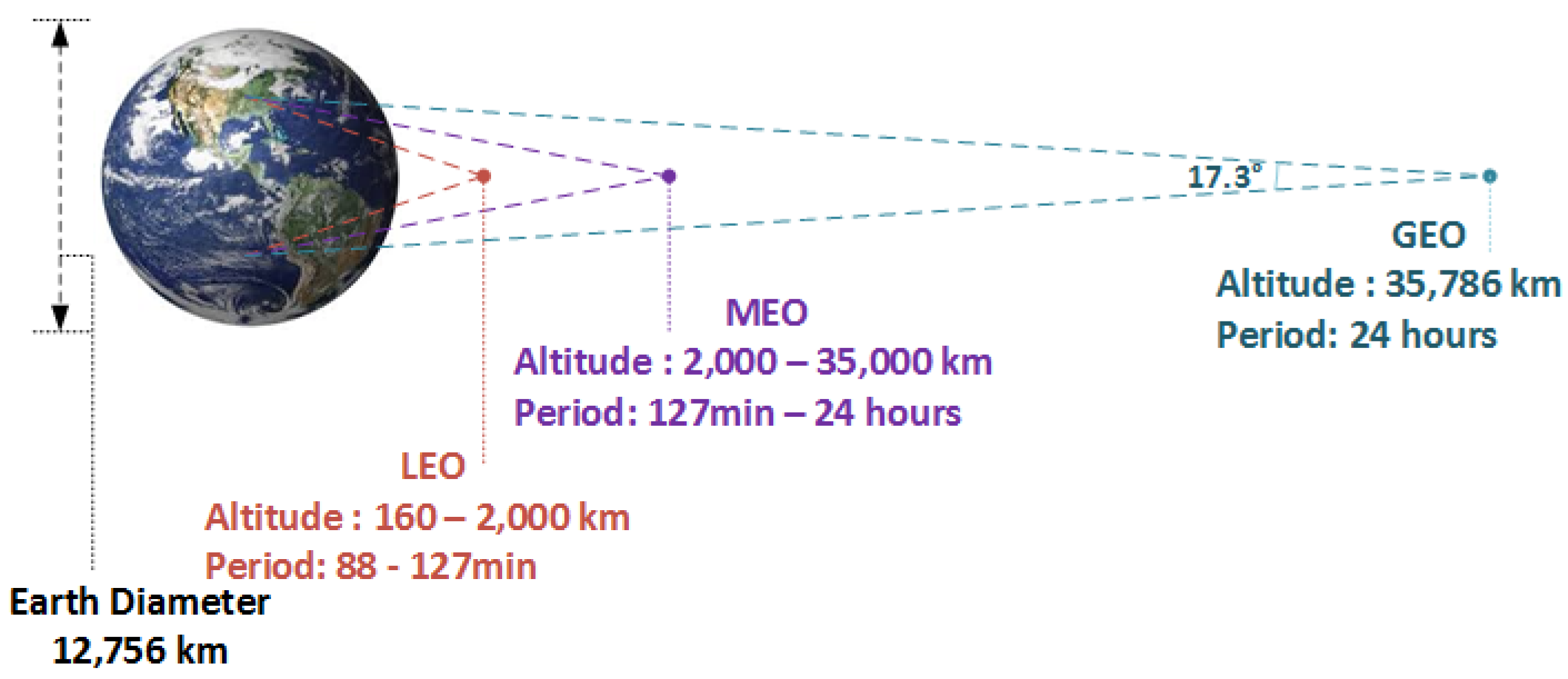
Figure 2.
Classification of satellites based on their mass and approximate power levels.
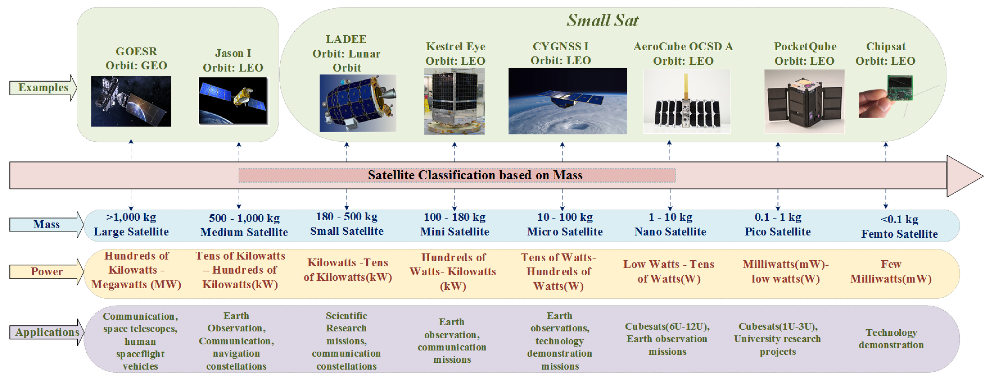
Figure 3.
Applications of DC-DC converters for satellites.
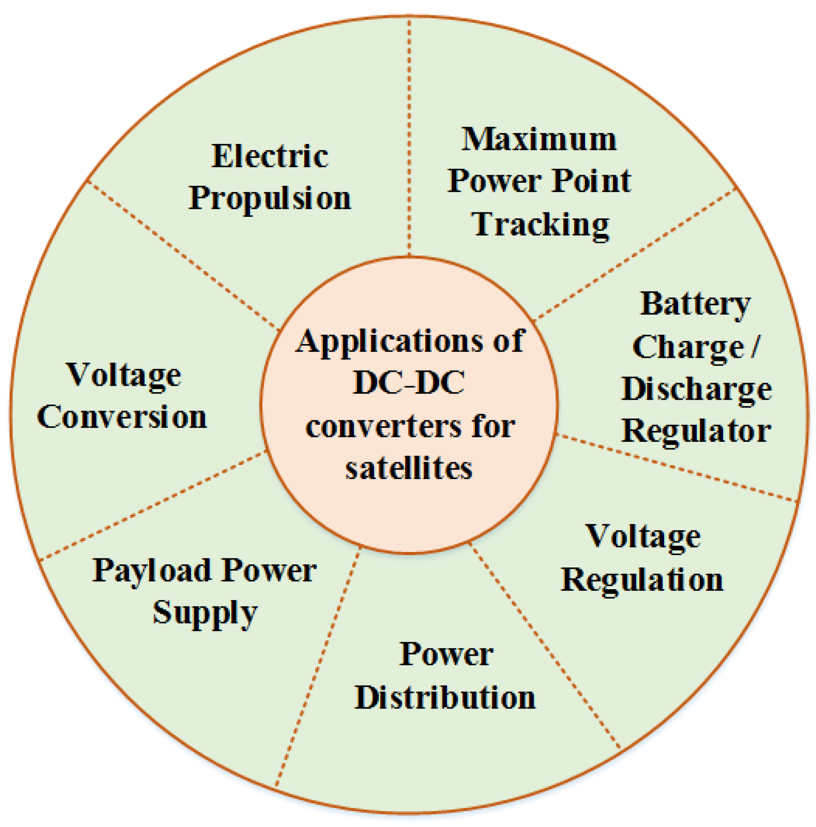
Figure 4.
Graphical abstract of the Paper.
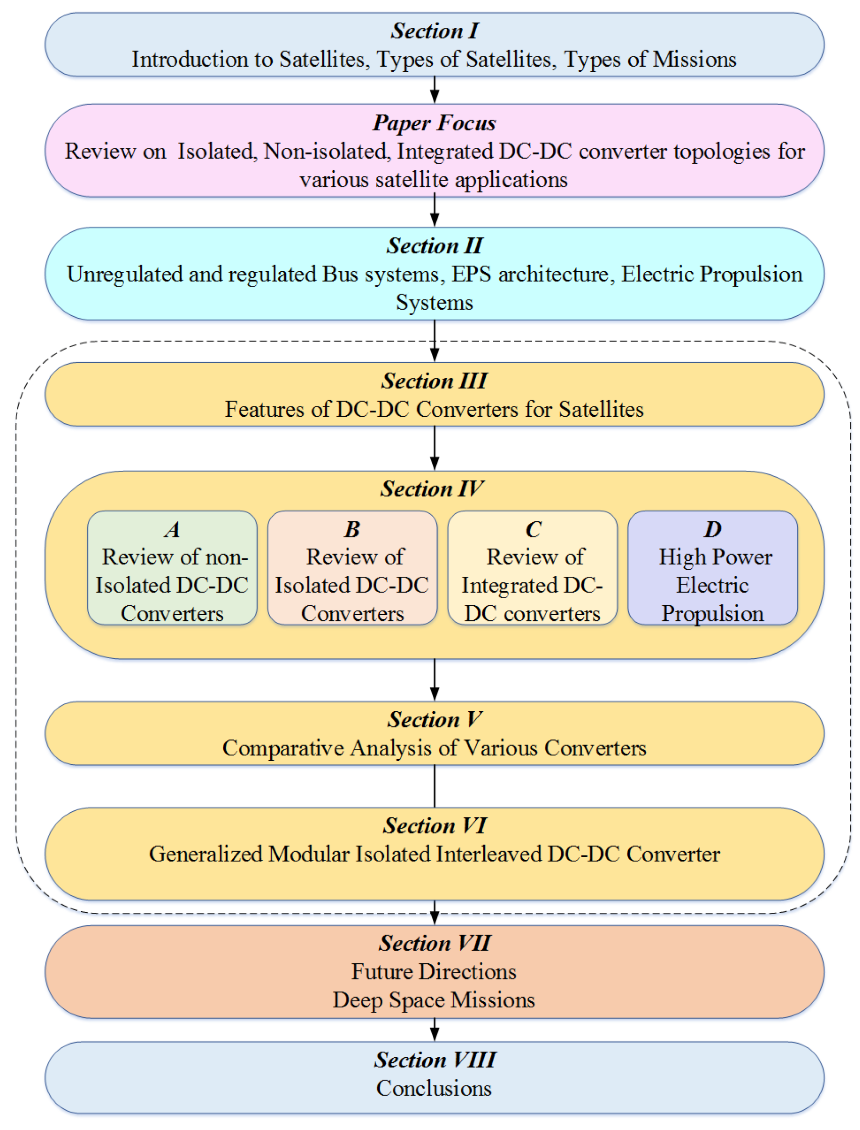
Figure 5.
EPS Bus System (a) Unregulated (b) Regulated and EPS Architecture for Power Distribution (c) DET and (d) MPPT. (e) Distributed Architecture (f) Decentralized Architecture with One Input and Many Outputs (g) Decentralized Architecture with Multiple Isolated Converters.
Figure 5.
EPS Bus System (a) Unregulated (b) Regulated and EPS Architecture for Power Distribution (c) DET and (d) MPPT. (e) Distributed Architecture (f) Decentralized Architecture with One Input and Many Outputs (g) Decentralized Architecture with Multiple Isolated Converters.
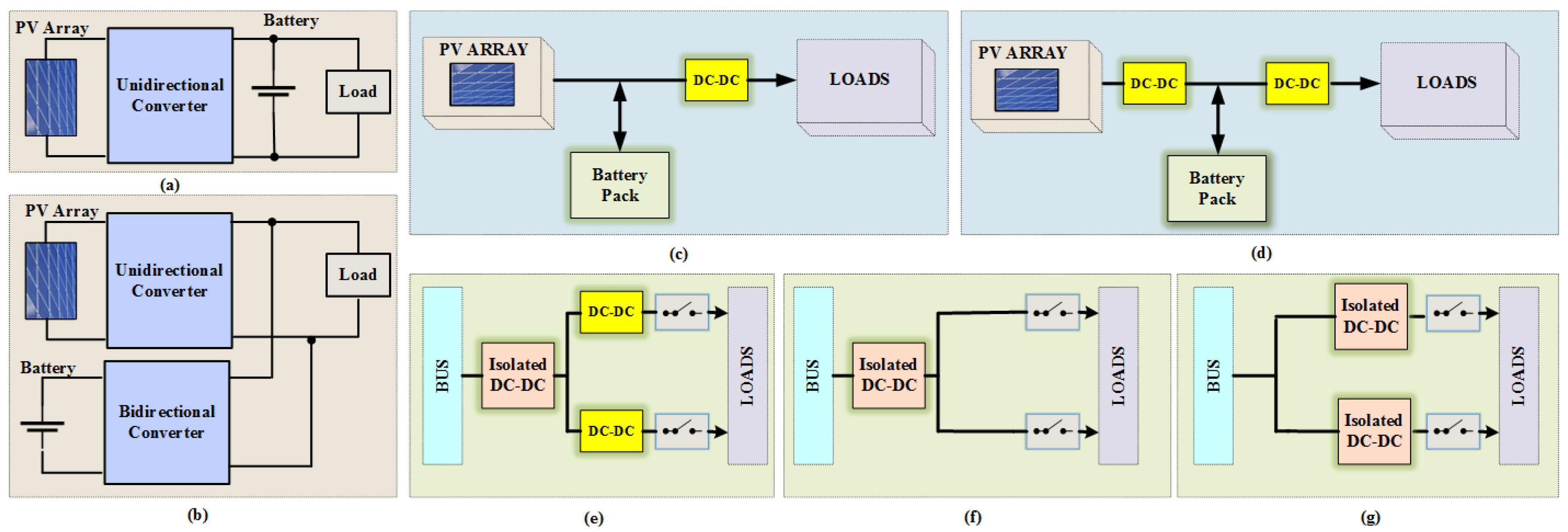
Figure 6.
Summary of various aspects of EP (Power sources for EP, Electric thrusters and their power levels, Evolution of Solar EP).
Figure 6.
Summary of various aspects of EP (Power sources for EP, Electric thrusters and their power levels, Evolution of Solar EP).
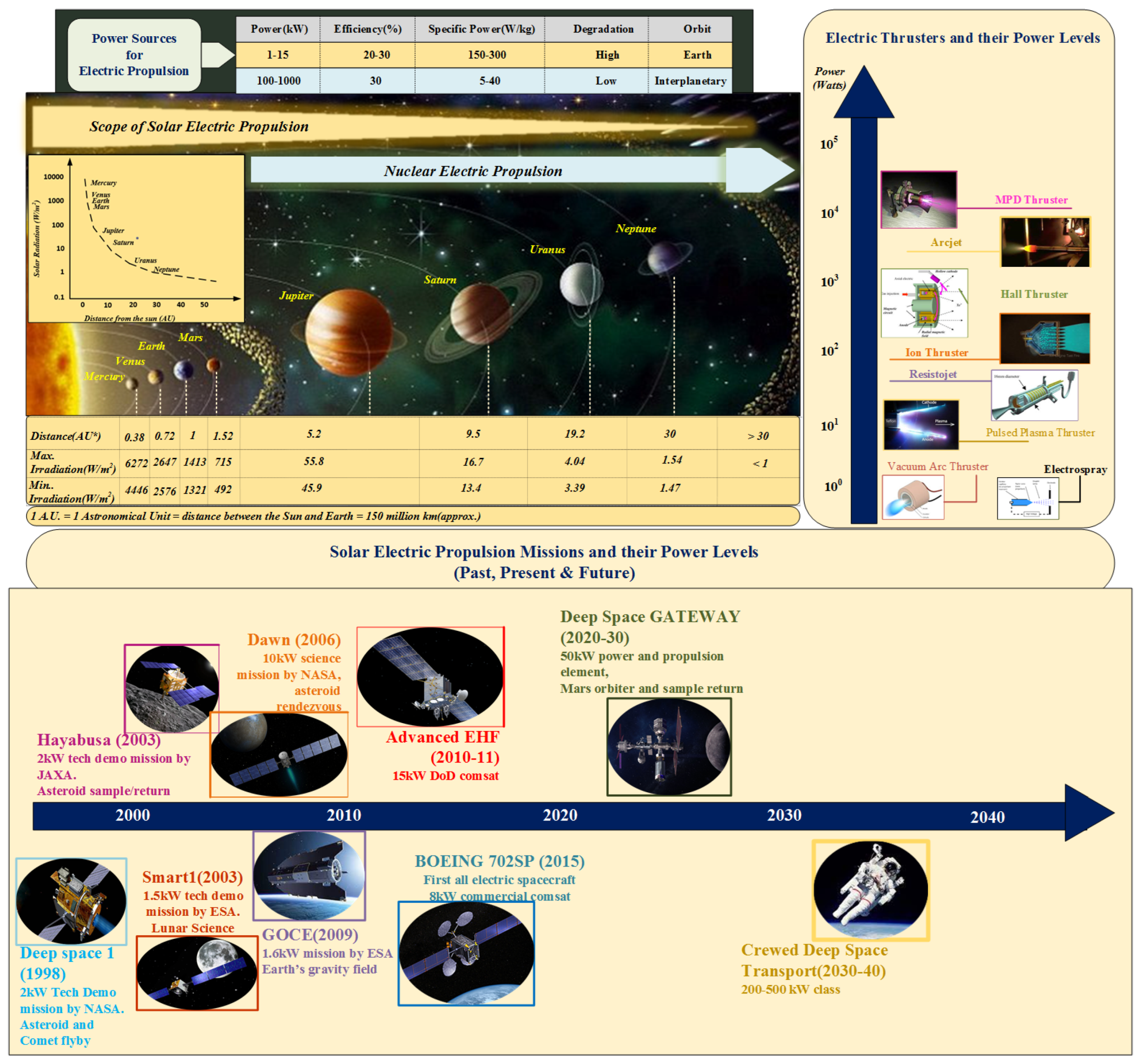
Figure 7.
Desirable Features of DC-DC Converters for Satellite Applications.
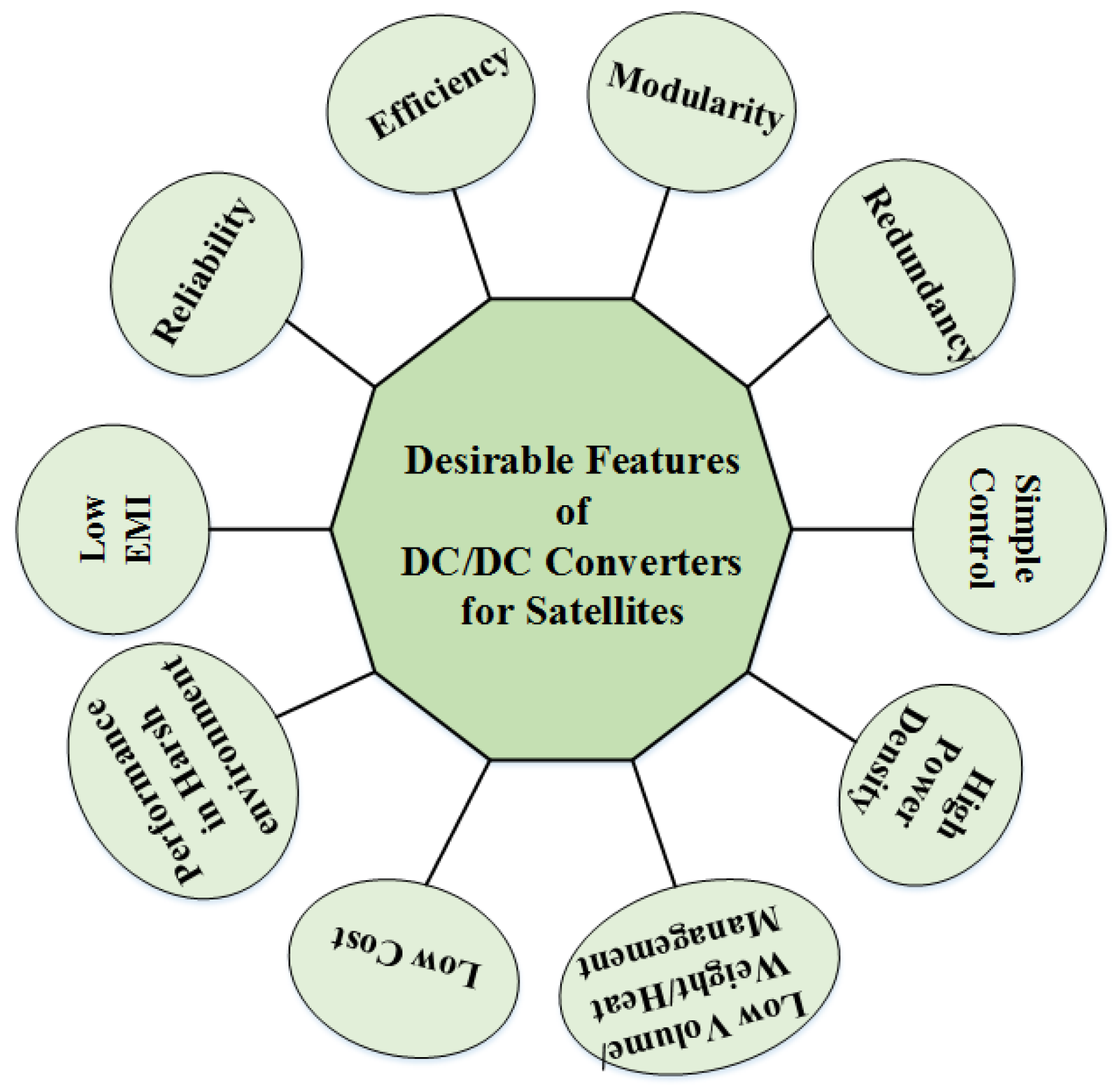
Figure 8.
Classification of non-isolated DC-DC converters for satellite applications.
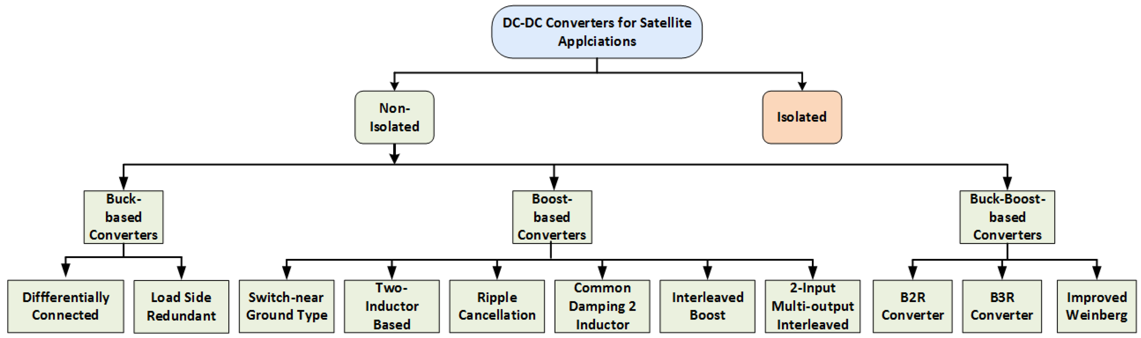
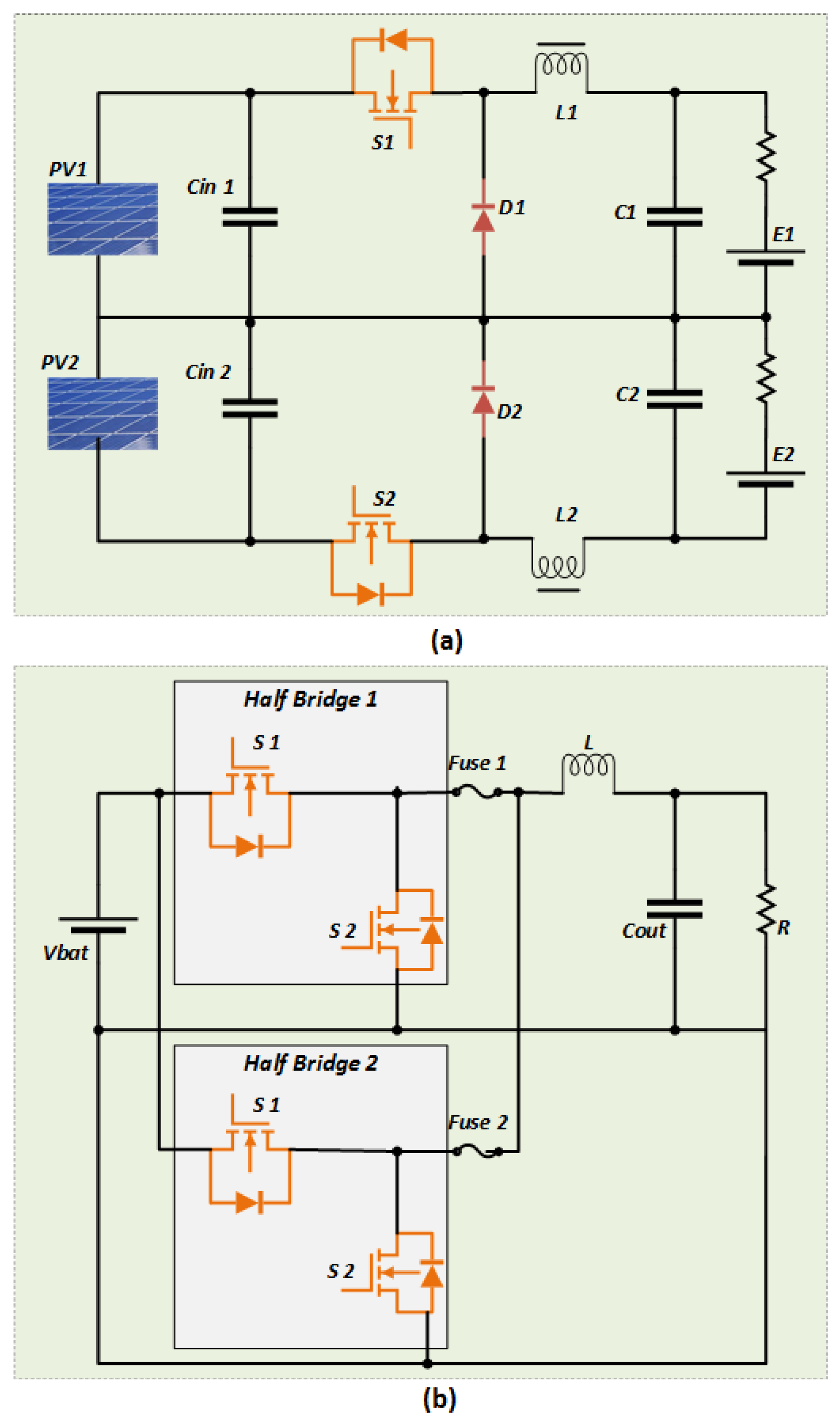
Figure 10.
Boost derived topologies (a) boost converter with a near switch ground (b) 2-inductor boost converter (c) ripple cancellation based Boost converter (d) common damping 2-inductor (e) interleaved(f) 2-input multiple output interleaved converter.
Figure 10.
Boost derived topologies (a) boost converter with a near switch ground (b) 2-inductor boost converter (c) ripple cancellation based Boost converter (d) common damping 2-inductor (e) interleaved(f) 2-input multiple output interleaved converter.
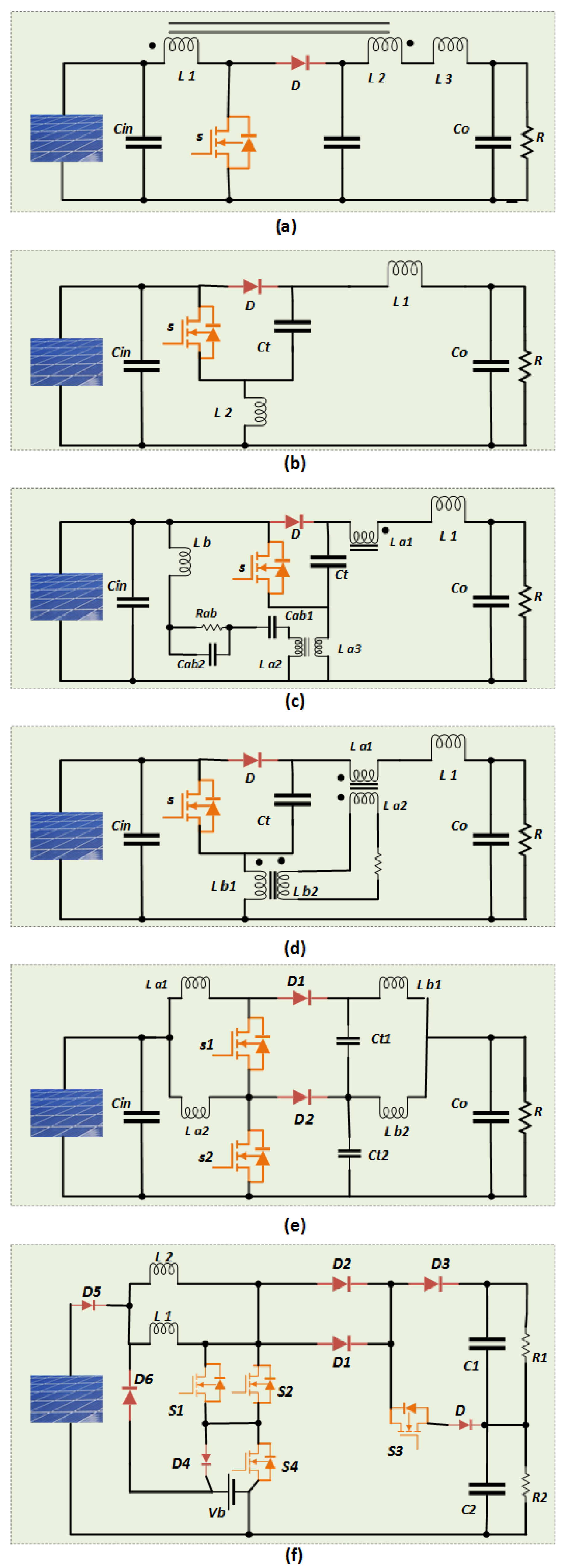
Figure 11.
Buck-Boost derived topologies (a) B2R converter(b) B3R converter(c) improved weinberg topology.
Figure 11.
Buck-Boost derived topologies (a) B2R converter(b) B3R converter(c) improved weinberg topology.
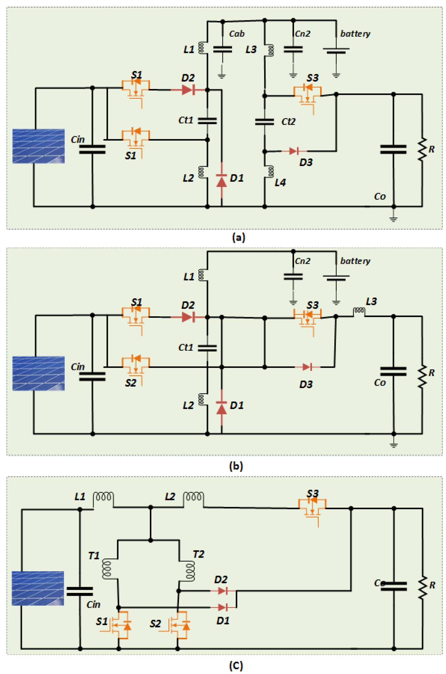
Figure 12.
Classification of Isolated DC-DC Converters for Satellite Applications.
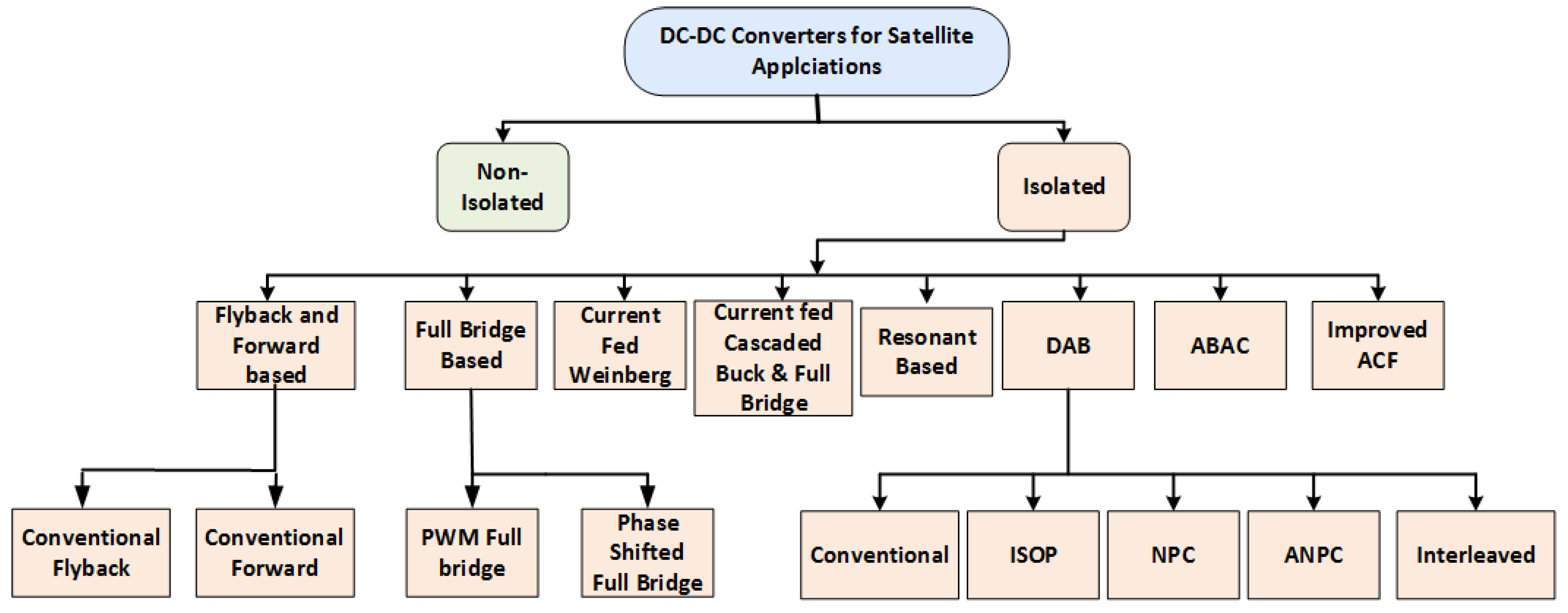
Figure 13.
Full-Bridge Converter.
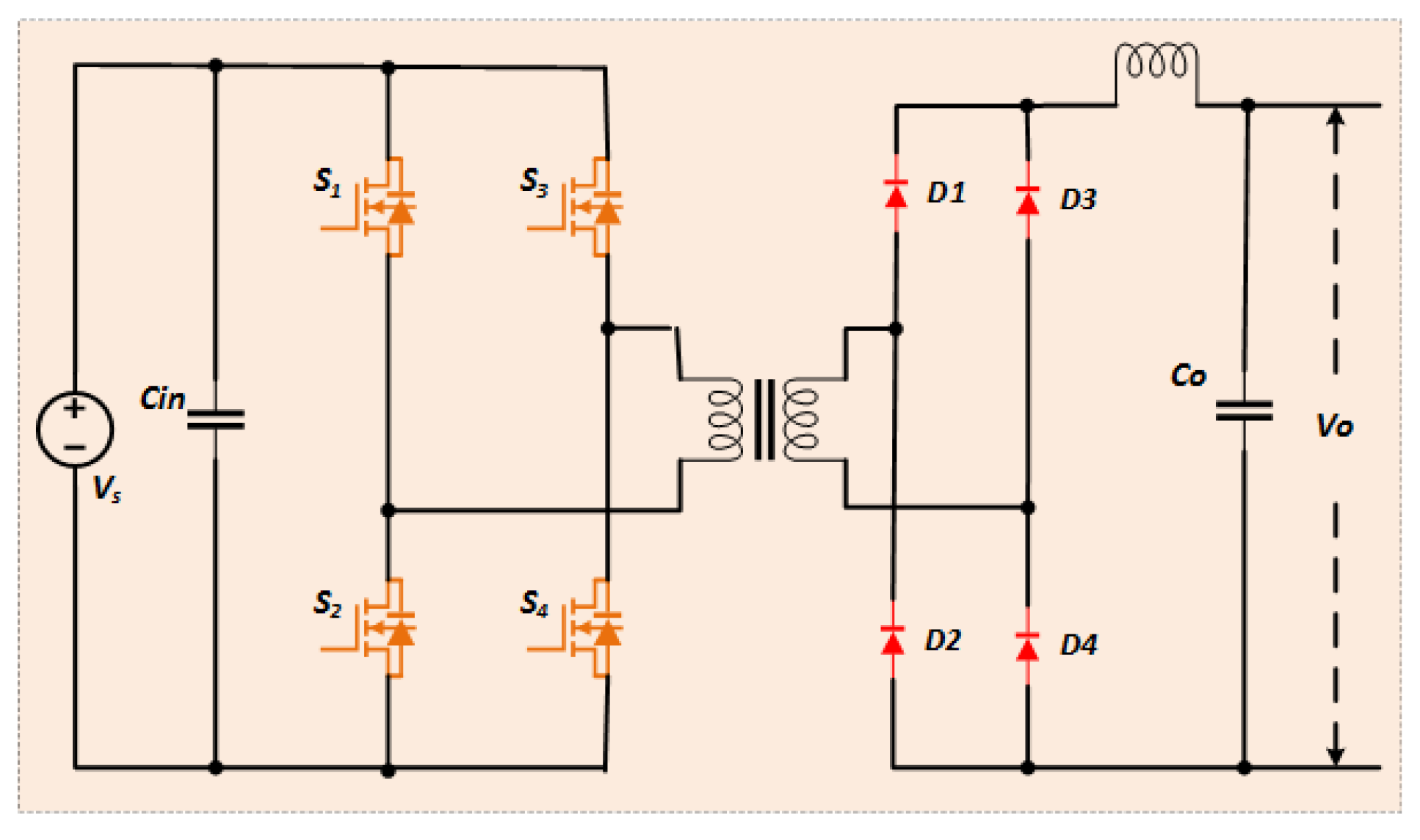
Figure 14.
Current-fed Weinberg converter.
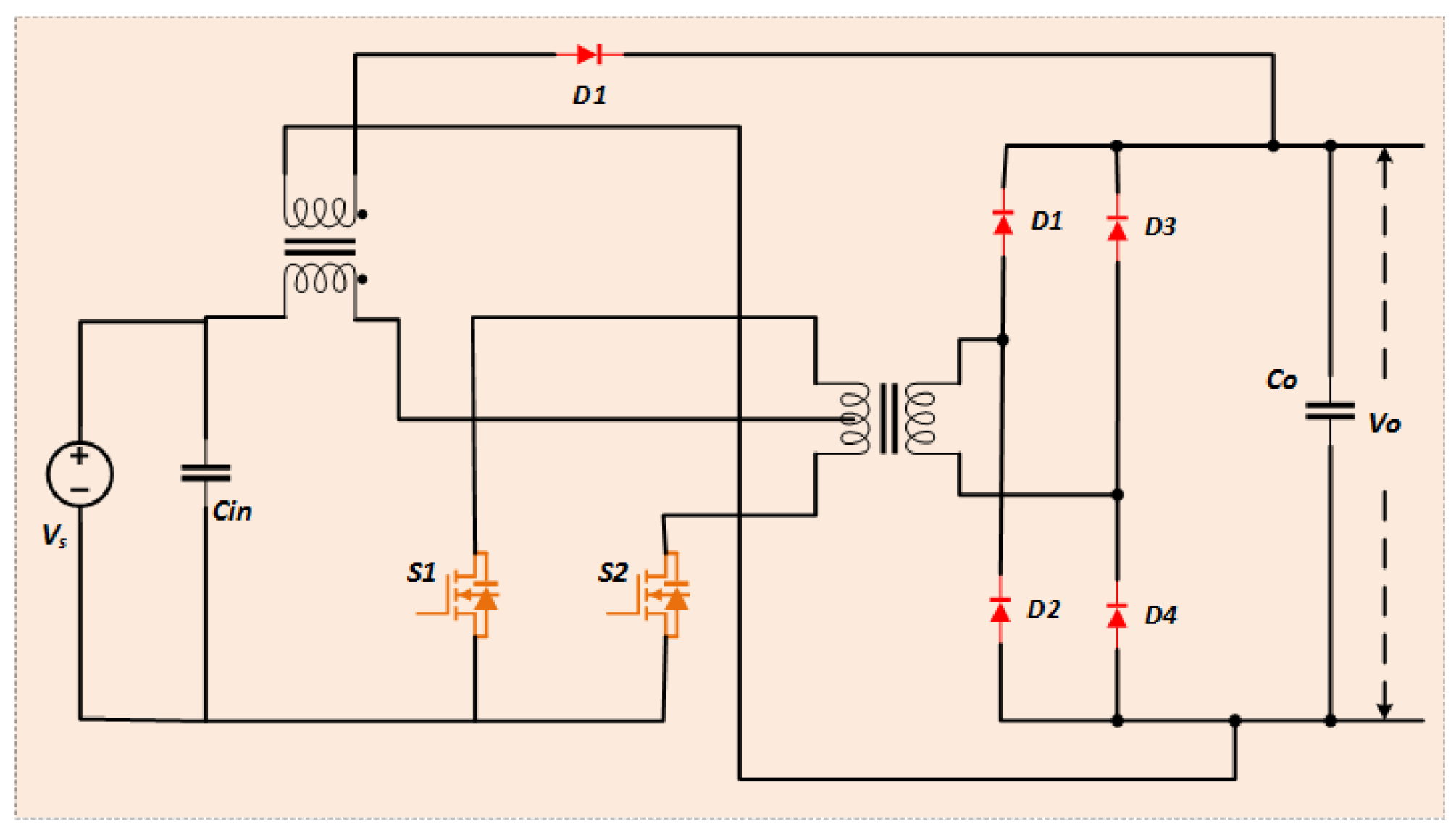
Figure 15.
Current-fed Cascaded Buck and Full Bridge Converter.
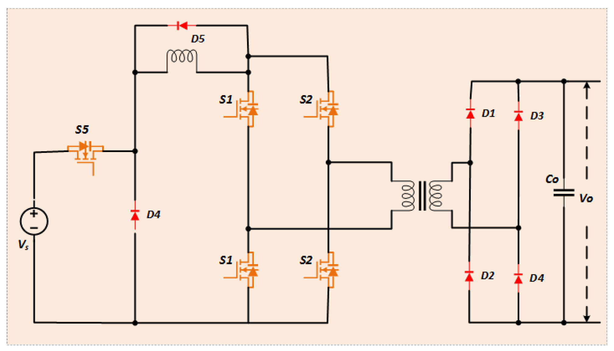
Figure 16.
Resonant LLC Converter.
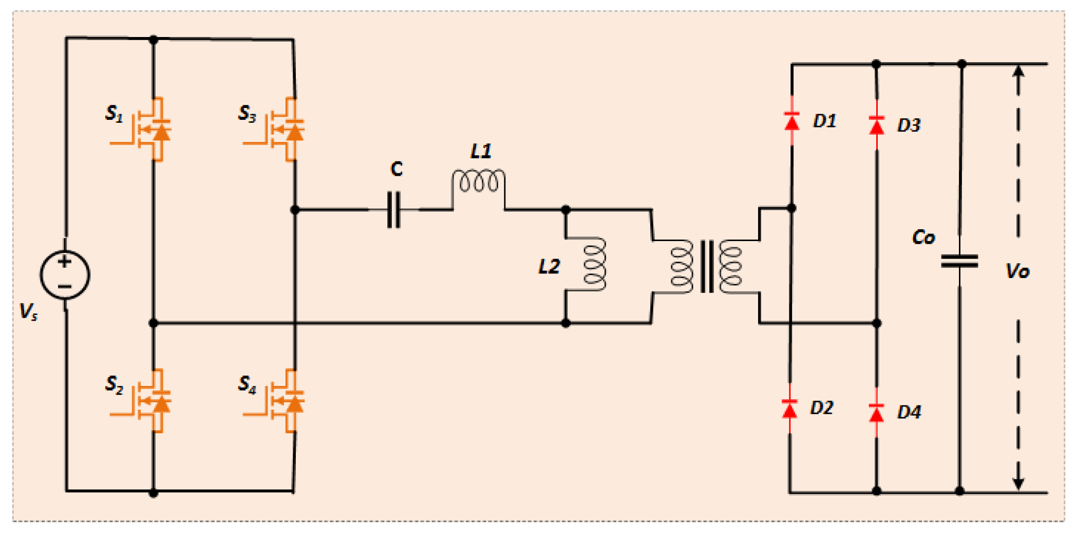
Figure 17.
DAB converter topologies (a) conventional (b) ISOP type (c) NPC type.

Figure 18.
DAB converter topologies (a) ANPC type (b)Parallel Interleaved type .
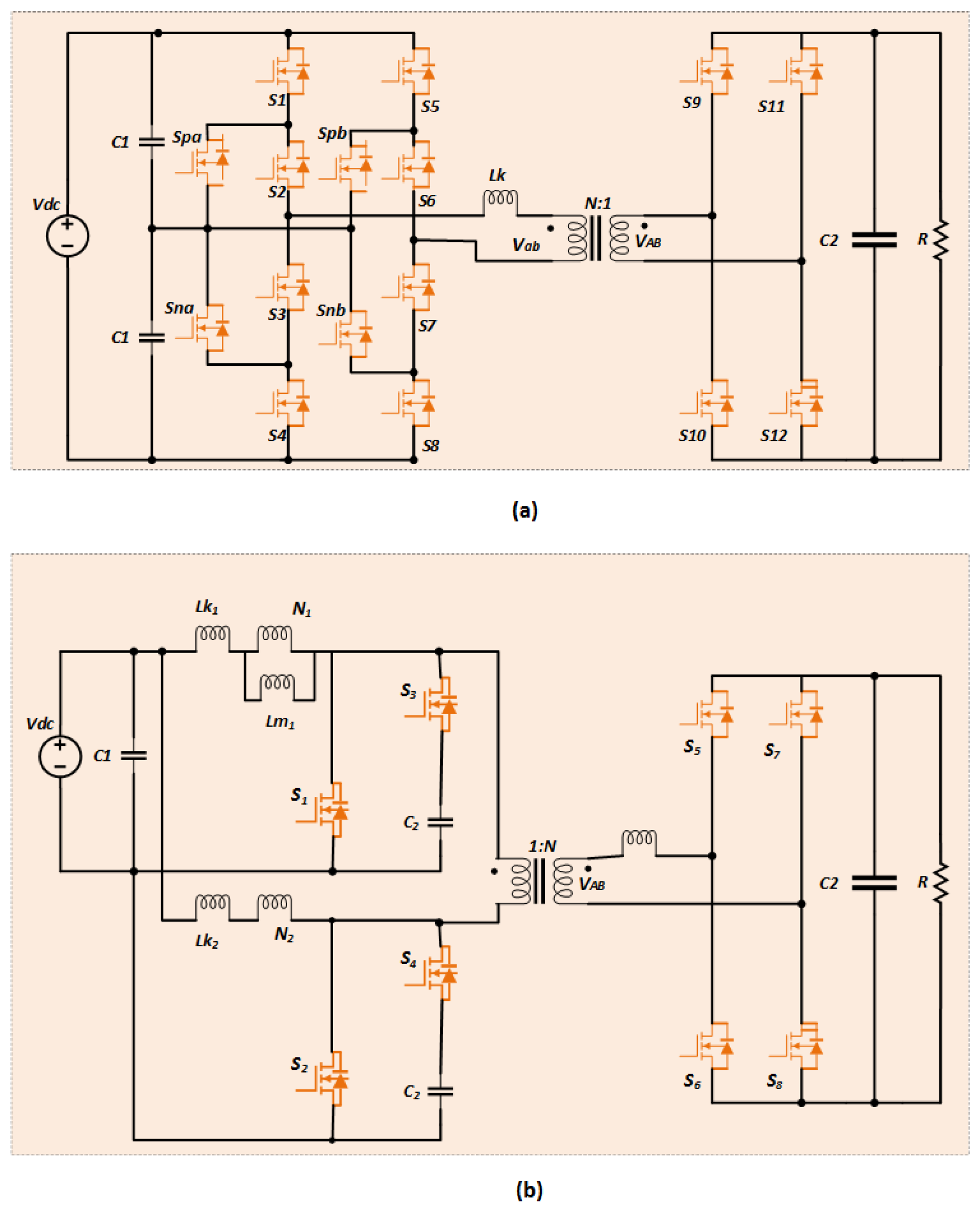
Figure 19.
Comparison of power density, thermal management, volume, efficiency and EMI of various DAB converters[80].
Figure 19.
Comparison of power density, thermal management, volume, efficiency and EMI of various DAB converters[80].
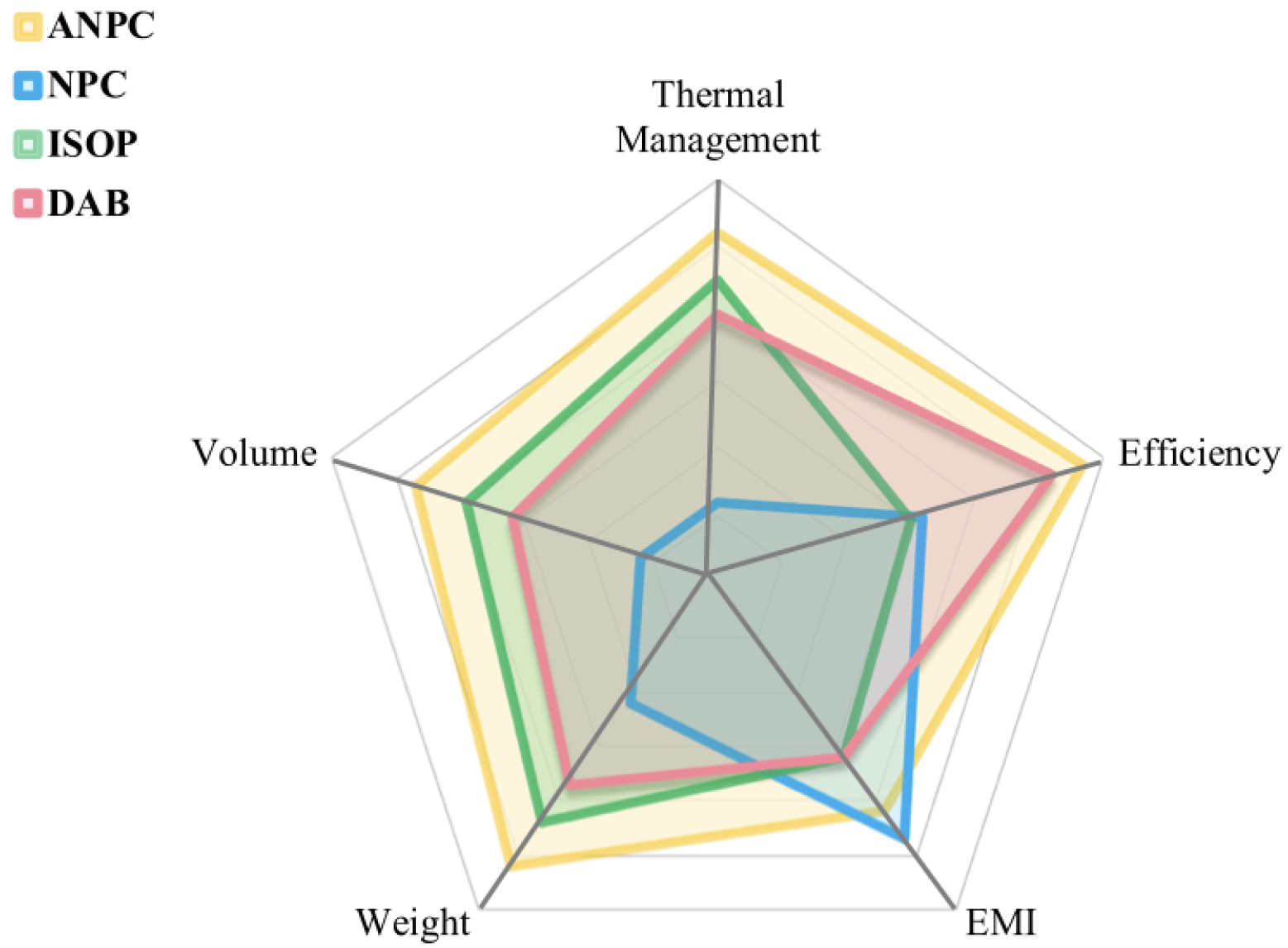
Figure 20.
Active bridge active clamp converter.

Figure 21.
Improved Active clamp forward converter.
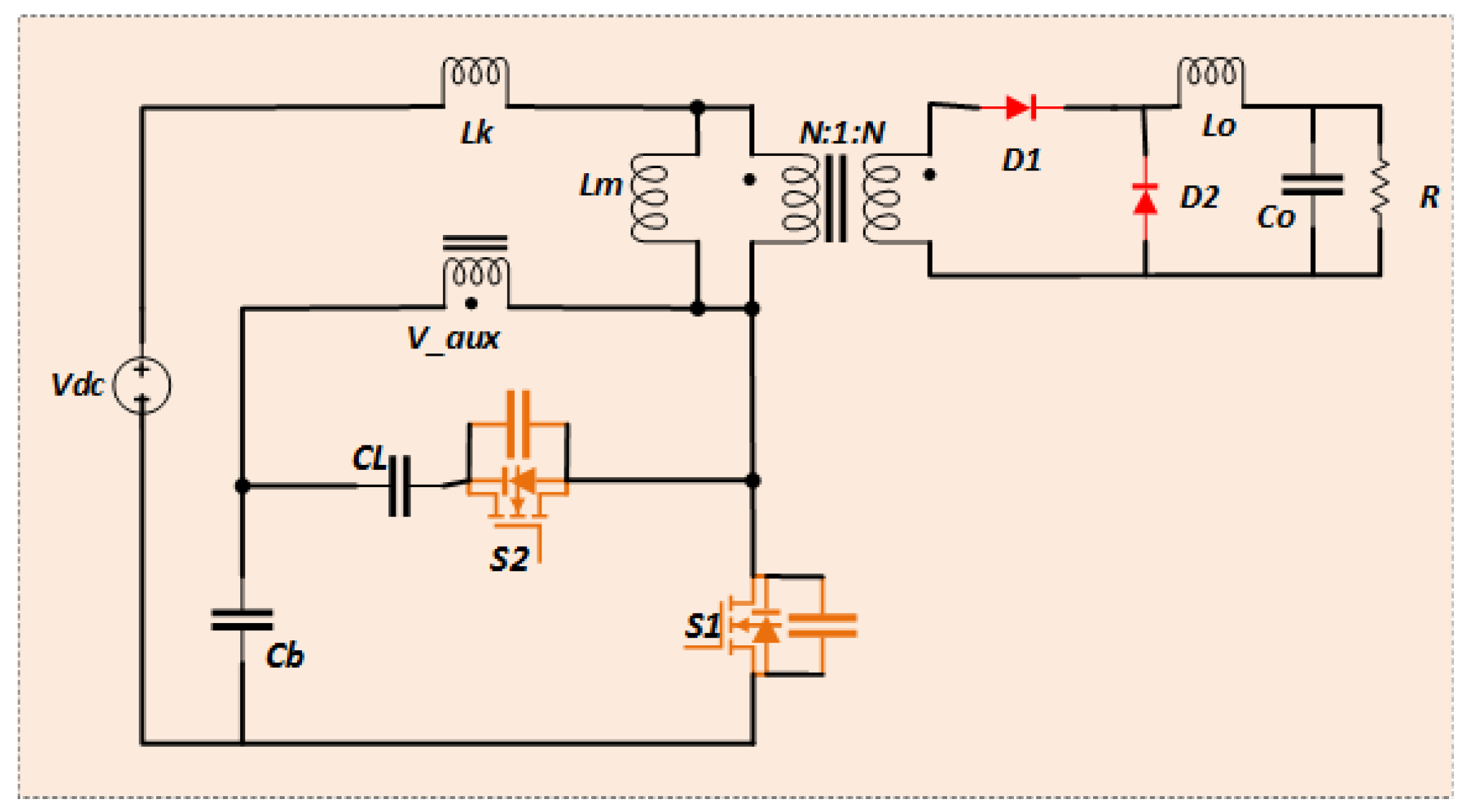
Figure 22.
Classification of Integrated Topologies of DC-DC Converters for Satellite Applications.
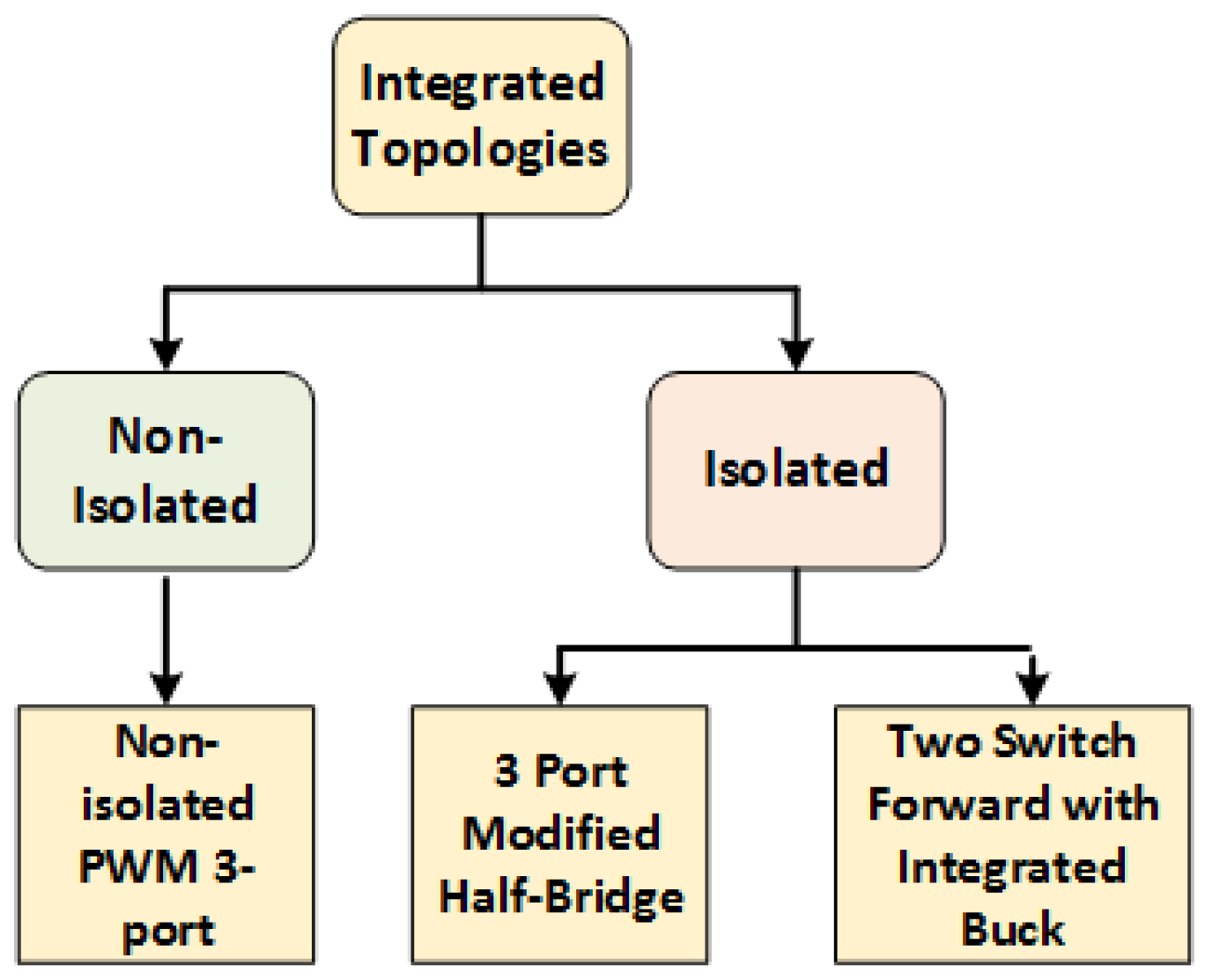
Figure 23.
Three-port modified half bridge converter.
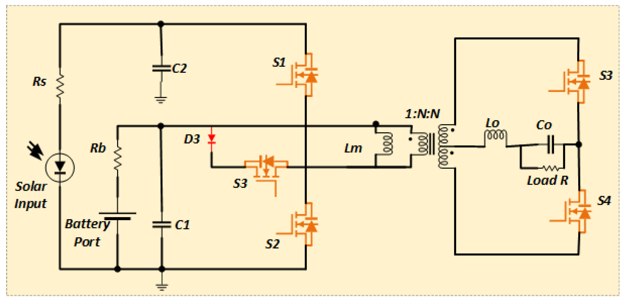
Figure 24.
Non isolated PWM TPC.
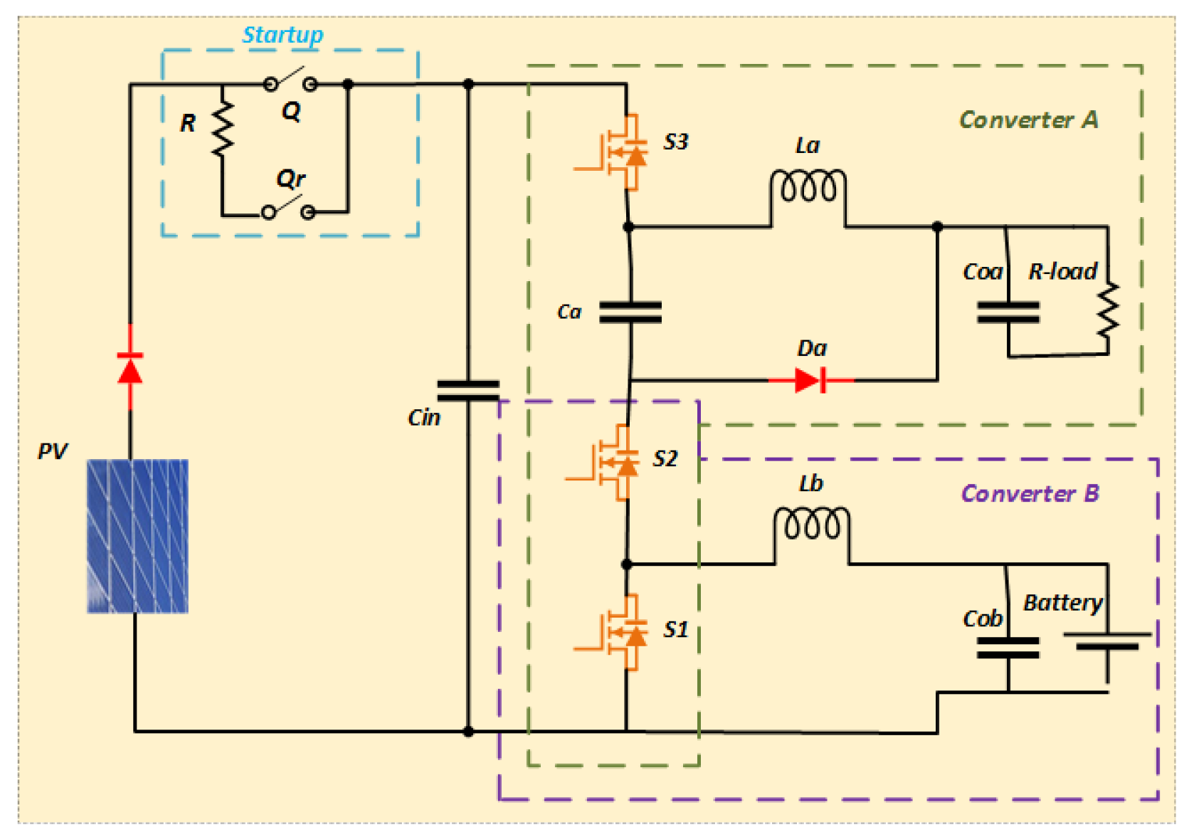
Figure 25.
Two switch forward with integrated Buck converter.
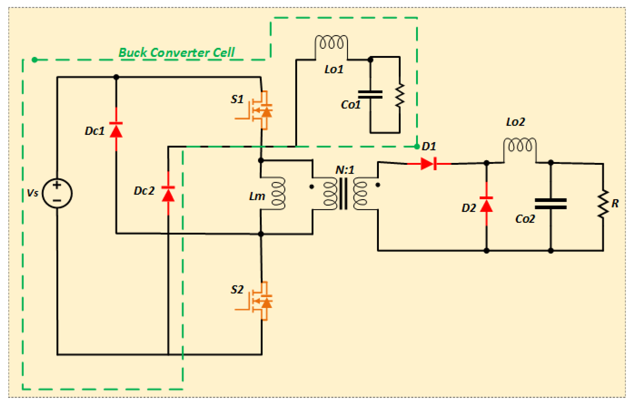
Figure 26.
Four-switch interleaved Buck-Boost converter.
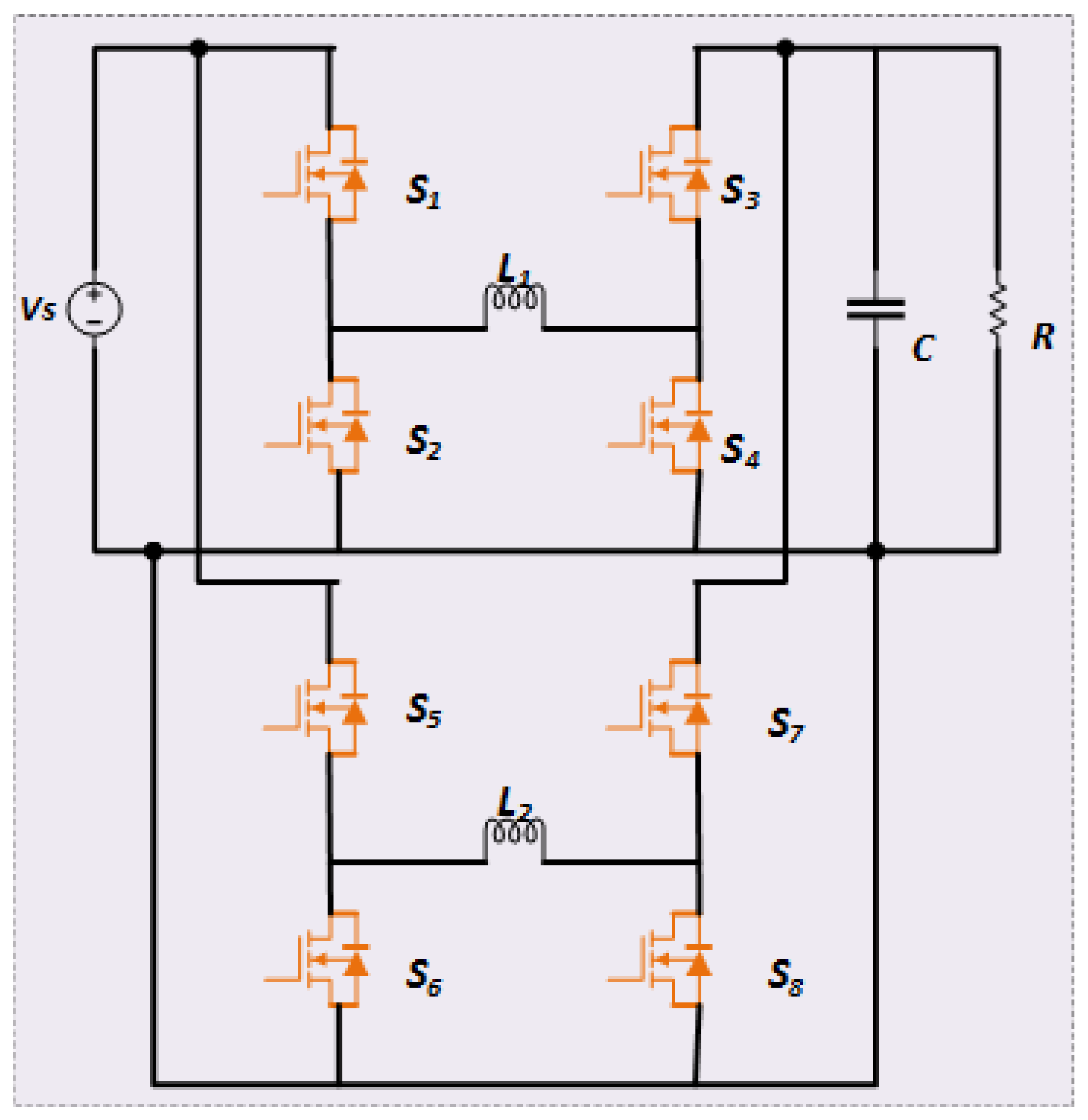
Figure 27.
Various performance indicators of DC-DC converters for satellite applications.
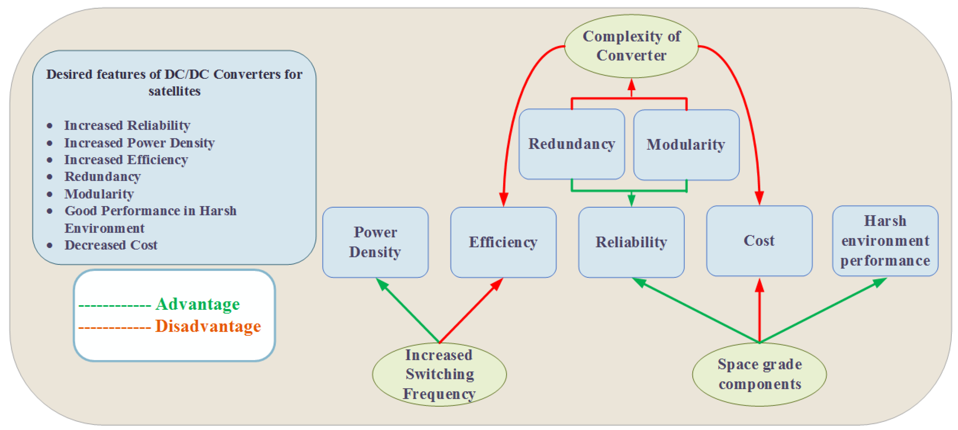
Figure 28.
(a) Generalized structure of Modular Interleaved converter(left) and one module of the converter with Full bridge on primary and Cuk converter on secondary (right) (b) Generalized control strategy of the proposed topology.
Figure 28.
(a) Generalized structure of Modular Interleaved converter(left) and one module of the converter with Full bridge on primary and Cuk converter on secondary (right) (b) Generalized control strategy of the proposed topology.
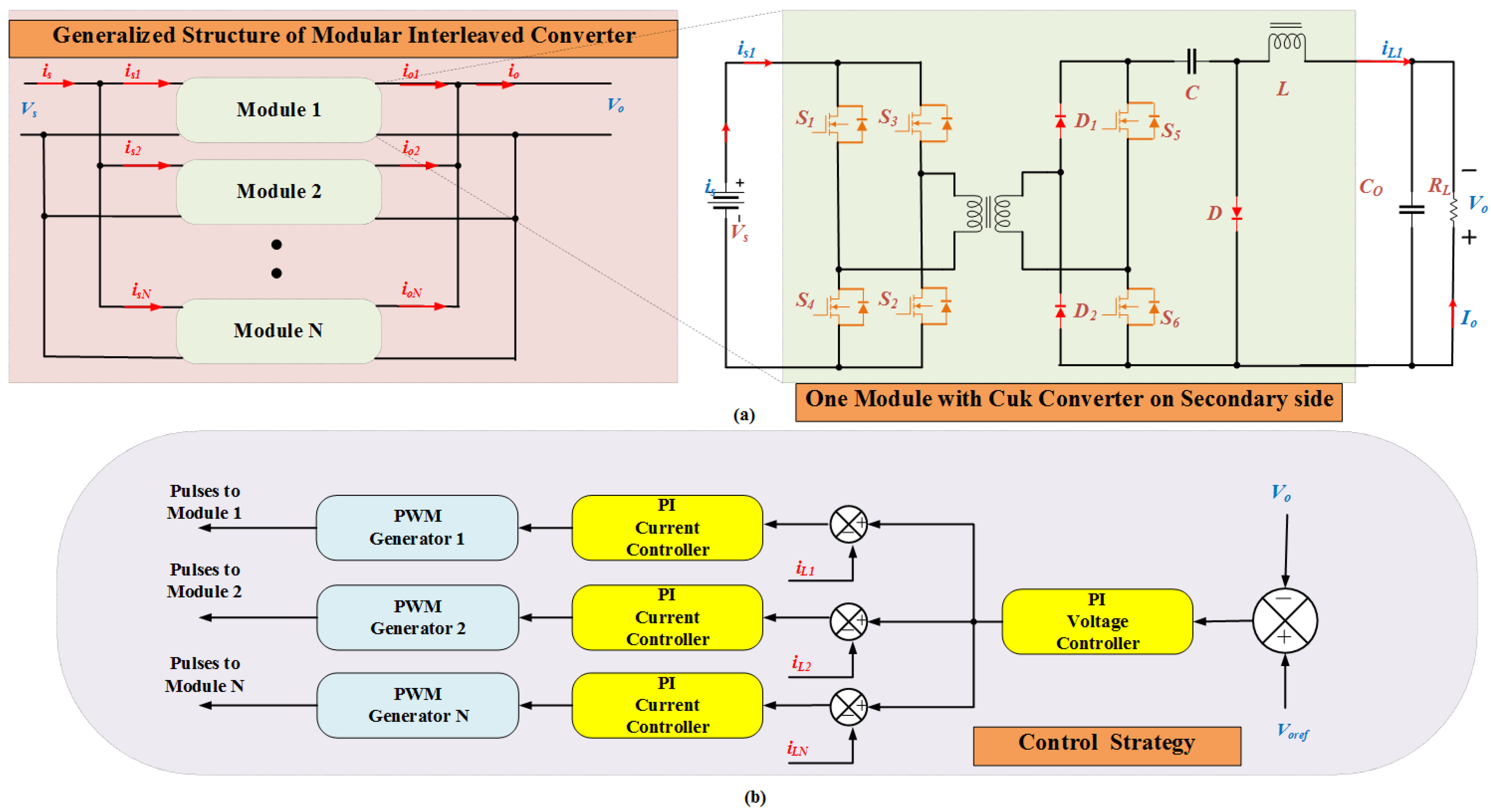
Figure 29.
Results of simulation for Modular Interleaved Converter based on Cuk topology with two modules (a) Output voltage and current (b) Switching pulses to secondary side switches to modules 1 and 2 (c) Switching pulses to primary side switches to modules 1 and 2 (d) Module Input currents and total input current (e) Module Inductor currents and total current (f) Output voltage for a step change in reference from to (g) Output voltage for a step change in input voltage from to .
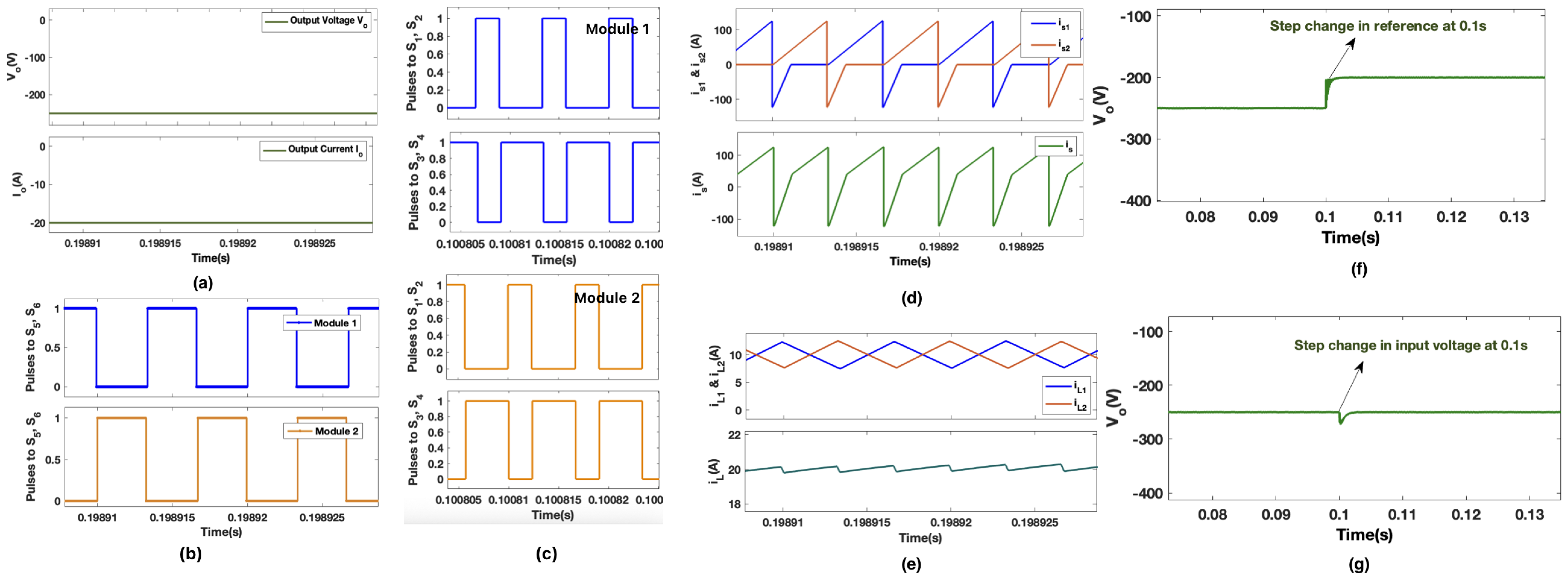
Figure 30.
Comparison of results for single module and three modules based Modular Interleaved Cuk converter (a) Inductor current for single module at switching frequency of (b)Inductor current for single module at switching frequency of (c) Module Inductor currents and total Inductor current for three modules at switching frequency of .
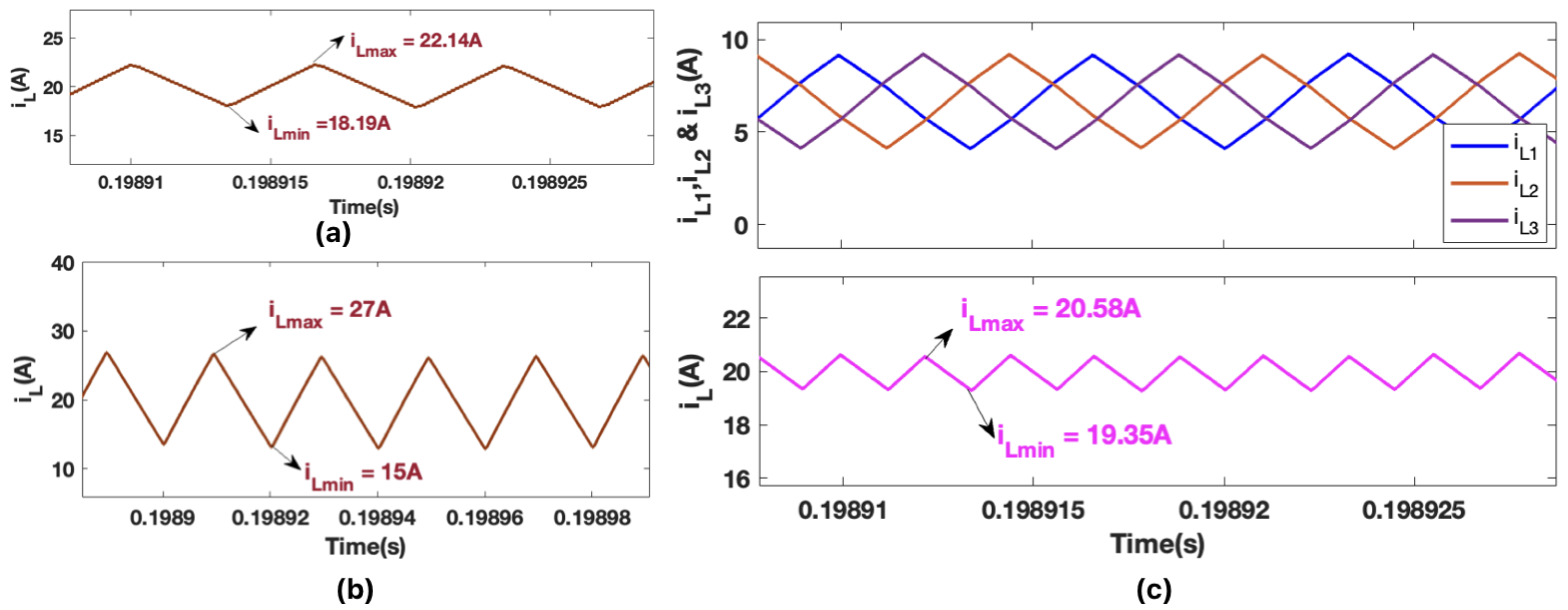
Figure 31.
(a) Variation of Switch and Diode current stresses with number of modules (b) Efficiency at full load Vs Number of modules.
Figure 31.
(a) Variation of Switch and Diode current stresses with number of modules (b) Efficiency at full load Vs Number of modules.

Figure 32.
Various deep space missions with their power and mass.
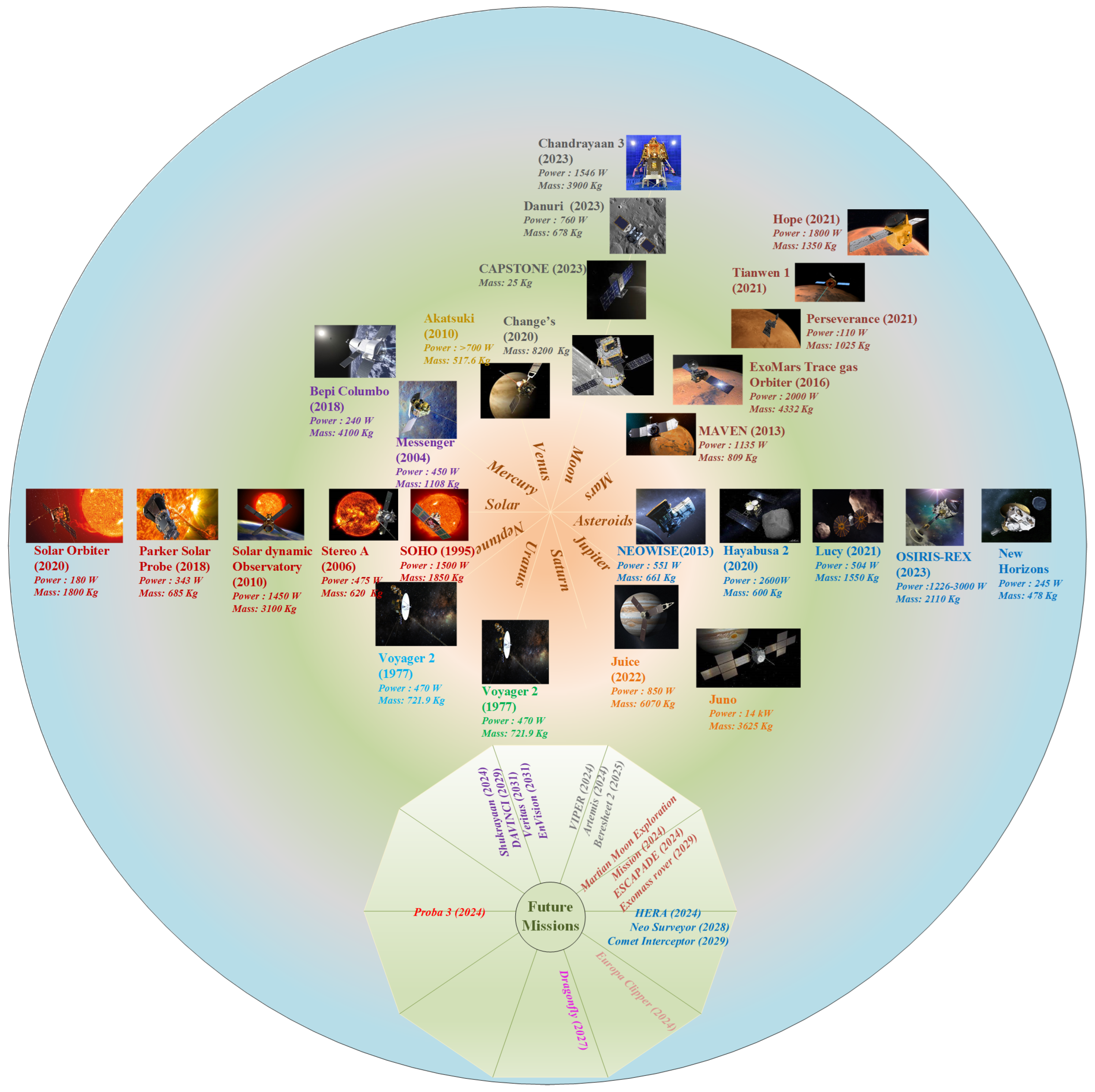

Table 1.
Comparison of various applications of high-power DC-DC converters.
| Features | Satellites | HVDC | Fuel | Electric | Photovoltaic | Electric |
| Cell | Vehicles | Array | Aircraft | |||
| Reliability | ✓ | ✓ | ✓ | ✓ | ✓ | ✓ |
| Redundancy | ✓ | ✓ | ✓ | |||
| Modularity | ✓ | ✓ | ✓ | ✓ | ||
| Power Density | ✓ | ✓ | ✓ | ✓ | ✓ | |
| EMI | ✓ | ✓ | ✓ | ✓ | ✓ | ✓ |
| Performance in Harsh | ✓ | ✓ | ||||
| Environmental Conditions | ||||||
| Efficiency | ✓ | ✓ | ✓ | ✓ | ✓ | ✓ |
Table 2.
Comparison of the present paper with recent review papers for Satellite DC-DC converters.
| Ref. | Type of Satellite | Converter Type | Application | Types of | Research | Topology | ||||
| gap | ||||||||||
| Comparison | highlighted | presented | ||||||||
| Large | Small | Non-Iso | Iso | Integrated | EP | |||||
| [32] | - | - | ✓ | x | x | x |
|
|
x | x |
| [33] | x | ✓ | ✓ | ✓ | ✓ | x |
|
|
x | x |
| This paper | ✓ | ✓ | ✓ | ✓ | ✓ | ✓ |
|
|
✓ | ✓ |
Table 3.
Comparison of various non-isolated DC-DC converters.
| Converter | Reference | Switching | Component Count | Type of | Power | uni/bi- | Main Features | |||
| Frequency | satellite | (W) | ||||||||
| (kHz) | S | D | L | C | ||||||
| Differentially Connected Buck [Figure 9a] | [33,58] | 400 | 2 | 2 | 2 | 4 | Nano-sat | 30 | Uni | Common Mode Noise rejection to reduce leakage current |
| Load Side Redundant Buck [Figure 9b] | [33,59] | - | 4 | 0 | 1 | 1 | Cube-sat | - | Uni | Redundant module for over-current protection |
| Switch near ground Boost [Figure 10a] | [32,33] | 130 | 1 | 1 | 3 | 3 | Small sat | 500 | Uni | Simple driving circuit direct energy transfer from input and output, high mass |
| [61] | 100 | 2 | 0 | 2 | 3 | Small sat | 5000 | Bi | Low mass and volume | |
| Two-Inductor based Boost [Figure 10b] | [32,33,62] | 130 | 1 | 1 | 2 | 2 | Small sat | 500 | uni | Continuous input and output currents, poor dynamic response. |
| Boost with ripple cancellation [Figure 10c] | [32,33,63] | 130 | 1 | 1 | 3 | 5 | Small sat | 500 | Uni | Ripple cancellation, high component count |
| Common damping 2-inductor boost [Figure 10d] | [32,33] | 130 | 1 | 1 | 1 | 3 | Small sat | 500 | - | High bandwidth, high loss in magnetic components |
| Interleaved Boost [Figure 10e] | [32,33] | 130 | 2 | 2 | 4 | 4 | Small sat | 500 | - | low output current ripple, good transient response, good transient response |
| Multi Output interleaved [Figure 10f] | [32,65] | 100 | 4 | 7 | 2 | 2 | - | 500 | - | |
| B2R Converter [Figure 11a] | [32,44] | 100 | 3 | 3 | 4 | 6 | - | 450 | - | Good voltage regulation |
| B3R Converter [Figure 11b] | [32,67] | - | 3 | 3 | 3 | 4 | - | - | - | Good voltage regulation, good transient response. |
| Improved Weinberg Converter [Figure 11c] | [32,68] | 50 | 3 | 2 | 4 | 2 | - | - | Bi | simple structure, high efficiency, and power density |
Table 4.
Comparison of various isolated DC-DC converters.
| Converter | Reference | Switching | Component | Power | uni/bi- | Main Features | |||
| Frequency | Count | (W) | directional | ||||||
| (kHz) | S | D | L | C | |||||
| Full-bridge converter [Figure 13] | [74] | 50 | 4 | 4 | 1 | 2 | 1000 | Bi | wide output voltage, good efficiency, shoot through problems. |
| Current Fed Weinberg Converter [Figure 14] | [74] | 50 | 2 | 5 | 0 | 2 | 500 | Bi | Shoot through tolerant, high efficiency, wide output voltage, suitable for LV applications, HV stress across switches. |
| [76] | 150 | 2 | 3 | 1 | 1 | 1500 | Bi | Fast dynamic response. | |
| Current-Fed Cascaded Buck and Full Bridge Converter [Figure 15] | [74] | 50 | 5 | 6 | 1 | 1 | 1000 | Bi | Shoot through tolerant, high component count, limitation in operating frequency, lower efficiency |
| Resonant LLC converter [Figure 16] | [74] | >200 | 4 | 4 | 2 | 2 | 1000 | Bi | High efficiency, Lower weight, high switching frequency, complex control circuitry. |
| Conventional DAB [Figure 17(a)] | [80] | - | 8 | 0 | 1 | 2 | - | Bi | Soft switching, Galvanic isolation, simple structure. |
| [54] | 100 | 8 | 0 | 1 | 2 | 8400 | Bi | ||
| ISOP-DAB [Figure 17b] | [80] | 16 | 0 | 2 | 4 | - | Bi | Low EMI noise, low efficiency. | |
| NPC-DAB [Figure 17c] | [80] | - | 12 | 4 | 1 | 3 | - | Bi | Low volume and weight, low EMI noise, low efficiency. |
| ANPC-DAB [Figure 18a] | [80] | - | 16 | 0 | 1 | 3 | - | Bi | High efficiency, good heat management, high power density. |
| Parallel interleaved DAB [Figure 18b] | [80] | 50 | 8 | 0 | 5 | 4 | 250 | Bi | |
| ABAC Converter [Figure 20] | [54,77] | 100 | 8 | 0 | 3 | 4 | 8400 | Uni | High efficiency, high power density. |
| ACF [Figure 21] | [86] | 300 | 2 | 2 | 3 | 3 | 100 | Uni | Reliable, light weight, low EMI noise, high power density. |
Table 5.
Comparison of various integrated DC-DC converters.
| Converter | Reference | Switching | Component | Power | Iso/non-iso | Main Features | |||
| Frequency | Count | (W) | directional | ||||||
| (kHz) | S | D | L | C | |||||
| Three-Port Modified Half Bridge Converter [Figure 23] | [37] | - | 5 | 1 | 2 | 3 | 200 | Isolated | Soft switching during turn-on, complex control technique. |
| Non-isolated PWM-Three-Port Converter [Figure 24] | [36] | 100 | 3 | 2 | 2 | 4 | 240 | Non-isolated | Simple circuit, reduced size. |
| Two Switch Forward with Integrated Buck Converter [Figure 25] | [17] | 100 | 2 | 4 | 3 | 2 | 600 | Isolated | Low mass and volume, ZVS switching, improved efficiency. |
Table 6.
Comparison of Various DC-DC Converters for EP in Satellites.
| Converter | Reference | Switching | Component | Power | Uni/Bi | Main Features | |||
| Frequency | Count | (W) | directional | ||||||
| (kHz) | S | D | L | C | |||||
| Resonant LLC [Figure 16] | [104] | >200 | 4 | 4 | 2 | 2 | 1000 | Bi | High efficiency, Lower weight, high switching frequency, complex control circuitry |
| 4 Parallel Converters [Figure 24] | [105] | 50 | - | - | - | - | 6000 | - | High efficiency over wide output range,low component count, parallel or serial switching of converters to obtain multiple output conditions |
| DAB [Figure 24] | [106,107] | - | 8 | 0 | 1 | 2 | 5000 | Bi | Soft switching, Galvanic isolation, simple structure. |
| DAB with Combined dual modulation [Figure 24] | [108] | - | 8 | 0 | 1 | 2 | 1000-5000 | Bi | Decreased EMI, a large output voltage range, high efficiency, and power density. |
| 4switch interleaved Buck-Boost + LLC resonant [Figure 26] | [109] | - | 8 | 0 | 2 | 1 | 1200 | Bi | Soft switching, low size of Inductor, high power density and efficiency. |
Table 7.
Comparison of various non-isolated DC-DC converters in terms of performance indicators.
| Converter | References | Figure | Reliability | Redundancy | Modularity | Power Density | Efficiency |
| Differentially connected Buck | [33,58] | Figure 9a | Medium | Yes | No | High | 97 |
| Load side redundant Buck | [33,59] | Figure 9b | High | Yes | No | - | - |
| Switch near ground Buck | [32,33] | Figure 10a | High | No | No | - | 96 |
| Two inductor based Boost | [32,33,62] | Figure 10b | High | No | No | - | >96 |
| Boost with ripple cancellation | [32,33,63] | Figure 10c | Medium | No | No | High | >96 |
| Common damping 2-inductor Boost | [32,33] | Figure 10d | High | No | No | - | >96 |
| Interleaved Boost | [32,33] | Figure 10e | High | Yes | yes | - | >96 |
| Multi output interleaved Boost | [32,65] | Figure 10f | High | Yes | Yes | - | 96 |
| B2R Converter | [32,44] | Figure 11a | Medium | No | No | - | 96 |
| B3R Converter | [32,67] | Figure 11b | Medium | No | No | - | High |
| Improved Weinberg converter | [32,68] | Figure 11c | Medium | No | No | - | High |
Table 8.
Comparison of various isolated DC-DC converters in terms of performance indicators.
| Converter | References | Figure | Reliability | Redundancy | Modularity | Power Density | Efficiency |
| Full bridge converter | [74] | Figure 13 | Medium | No | No | Medium | 95 |
| Current fed Weinberg converter | [74] | Figure 14 | High | No | No | Medium | 95 |
| Current fed cascaded buck and full bridge converter | [74] | Figure 15 | Medium | No | No | Medium | 90-95 |
| Resonant LLC converter | [74] | Figure 16 | Medium | No | No | Medium | 95-98 |
| Conventional DAB | [80] | Figure 17a | High | No | No | Medium | High |
| ISOP-DAB | [80] | Figure 17b | High | Yes | Yes | Medium | High |
| NPC-DAB | [80] | Figure 17c | Low | No | No | Low | Low |
| ANPC-DAB | [80] | Figure 18a | Low | No | No | High | High |
| Parallel interleaved DAB | [80] | Figure 18b | High | Yes | Yes | High | - |
| ABAC converter | [54,77] | Figure 20 | Low | Yes | Yes | High | High |
| ACF converter | [86] | Figure 21 | High | Yes | Yes | High | 90-95 |
Table 9.
Comparison of various integrated DC-DC converters in terms of performance indicators.
| Converter | References | Figure | Reliability | Redundancy | Modularity | Power Density | Efficiency |
| Three port modified half bridge converter | [37] | Figure 23 | Low | No | No | Low | High |
| Non-isolated PWM three port converter | [36] | Figure 24 | Medium | No | No | Medium | 97.3 |
| Two switch Forward with integrated Buck converter | [17] | Figure 25 | High | No | No | High | 95 |
Table 10.
Comparison of various high-power DC-DC converters in PPU for EP.
| Converter | Ref. | Figure | Type of | Reliability | Redundancy | Modularity | Power | Efficiency |
| thruster | Density | |||||||
| Resonant LLC | [104] | Figure 16 | Hall thruster | Medium | No | No | High | > 95 |
| 4 parallel converters | [105] | - | Hall thruster | High | No | Yes | High | 96.1 |
| DAB | [106,107] | Figure 24 | Ion thruster | Medium | No | No | High | High |
| DAB with combined dual modulation | [108] | Figure 24 | - | High | No | No | High | - |
| 4switch interleaved Buck-Boost + LLC resonant | [109] | Figure 26 | Ion thruster | High | No | Yes | High | High |
Table 11.
Comparison of the selected topologies based on their application in satellites and type of satellite.
Table 11.
Comparison of the selected topologies based on their application in satellites and type of satellite.
| Application | Figure | Reference | Large | Small | Mini | Micro | Nano | Pico | Femto |
| MPPT | Figure 9a | [33,58] | ✓ | ✓ | ✓ | ||||
| Figure 9b | [33,59] | ✓ | ✓ | ||||||
| Figure 10a | [32,33] | ✓ | ✓ | ||||||
| Figure 10b | [32,33,62] | ✓ | ✓ | ||||||
| Figure 10c | [32,33,63] | ✓ | ✓ | ||||||
| Figure 10d | [32,33] | ✓ | ✓ | ||||||
| Figure 10e | [32,33] | ✓ | ✓ | ||||||
| Figure 10f | [32,65] | ✓ | ✓ | ||||||
| Figure 11a | [32,44] | ||||||||
| Figure 11b | [32,67] | ||||||||
| Figure 11c | [32,68] | ||||||||
| Battery Regulator | Figure 10f | [32,65] | ✓ | ✓ | |||||
| Figure 11a | [32,44] | ||||||||
| Figure 11b | [32,67] | ||||||||
| Figure 11c | [32,68] | ||||||||
| Voltage Regulation | Figure 9a | [33,58] | ✓ | ✓ | ✓ | ||||
| Figure 9b | [33,59] | ✓ | ✓ | ✓ | |||||
| Figure 10a | [32,33] | ✓ | ✓ | ||||||
| Figure 10b | [32,33,62] | ✓ | ✓ | ||||||
| Figure 10c | [32,33,63] | ✓ | ✓ | ||||||
| Figure 10d | [32,33] | ✓ | ✓ | ||||||
| Figure 10e | [32,33] | ✓ | ✓ | ||||||
| Figure 10f | [32,65] | ✓ | ✓ | ||||||
| Figure 11a | [32,44] | ||||||||
| Figure 11b | [32,67] | ||||||||
| Figure 11c | [32,68] | ||||||||
| Multi-port Conversion | Figure 23 | [37] | ✓ | ✓ | ✓ | ✓ | ✓ | ✓ | |
| Figure 24 | [36] | ✓ | ✓ | ✓ | ✓ | ✓ | ✓ | ||
| Figure 25 | [17] | ✓ | ✓ | ✓ | ✓ | ✓ | ✓ | ||
| Electric Propulsion | Figure 16 | [74] | ✓ | ✓ | |||||
| Figure 17a | [80] | ✓ | ✓ | ||||||
| Figure 26 | [109] | ✓ | ✓ | ||||||
| Power distribution | Figure 13 | [74] | ✓ | ✓ | |||||
| Figure 14 | [74] | ✓ | ✓ | ||||||
| Figure 15 | [74] | ✓ | ✓ | ||||||
| Figure 16 | [74] | ✓ | ✓ | ||||||
| Figure 17a | [80] | ✓ | ✓ | ||||||
| Figure 17b | [80] | ✓ | ✓ | ||||||
| Figure 17c | [80] | ✓ | ✓ | ||||||
| Figure 18a | [80] | ✓ | ✓ | ||||||
| Figure 18b | [80] | ✓ | ✓ | ||||||
| Figure 20 | [54,77] | ✓ | ✓ | ||||||
| Figure 21 | [86] | ✓ | ✓ |
Table 12.
Design Parameters for Simulation Model.
| Parameter | Overall | Module 1 | Module 2 |
| Rated Power | |||
| Input Voltage | |||
| Output Voltage | |||
| Switching frequency | |||
| Load resistance | |||
| Output Capacitor | |||
| Cuk Capacitor | |||
| Output Inductor |
Table 13.
Research Gaps in Various Space Applications(Contd.)
| Area of research | Gaps |
| Design and development of DC-DC converters |
|
| Adoption of Solar EP / Nuclear EP |
|
| Deep Space Exploration |
|
| Electronic Components for space applications |
|
| Solar Based Power Satellites |
|
Disclaimer/Publisher’s Note: The statements, opinions and data contained in all publications are solely those of the individual author(s) and contributor(s) and not of MDPI and/or the editor(s). MDPI and/or the editor(s) disclaim responsibility for any injury to people or property resulting from any ideas, methods, instructions or products referred to in the content. |
© 2024 by the authors. Licensee MDPI, Basel, Switzerland. This article is an open access article distributed under the terms and conditions of the Creative Commons Attribution (CC BY) license (http://creativecommons.org/licenses/by/4.0/).
Copyright: This open access article is published under a Creative Commons CC BY 4.0 license, which permit the free download, distribution, and reuse, provided that the author and preprint are cited in any reuse.


