

Submitted:
05 July 2025
Posted:
07 July 2025
You are already at the latest version
Abstract
This paper proposes a superconducting shielding model based on the Meissner effect, achieving intermittent magnetic field shielding through phase transition cycles to form time-varying non-conservative fields in specific regions. According to the reversible phase transitions of the superconducting Meissner effect and the law of energy conservation, analysis of the entire closed-space model reveals that while the superconductor’s energy remains conserved, the loop integral of electromagnetic force on the moving magnet is non-zero, leading to electromagnetic energy non-conservation. Furthermore, analysis of the overall model indicates that changes in the magnetic potential energy of the moving magnet, under constant energy conditions for other components, also result in electromagnetic energy non-conservation. COMSOL simulations validate the dynamic characteristics of magnetic shielding, aligning with theoretical predictions.
Keywords:
reversible phase transitions
; Meissner effect
; superconducting shielding
; energy conservation
; non-conservative field
; COMSOL simulation
1. Introduction
1.1. Thermodynamic Reversibility of Phase Transitions
Thermodynamics is fundamentally grounded in reversible phase transitions. Prior to the discovery of the Meissner effect, superconductors were assumed to behave as ideal conductors. When superconductivity breaks down, the normal phase exhibits resistance, and currents associated with magnetic fields generate heat. This implied that superconducting phase transitions were non-equilibrium processes, rendering thermodynamic analysis seemingly inapplicable. Keesom(1924)established thermodynamic formulae for superconducting phase transitions, which aligned well with experimental observations. Later, Gorter (1933) argued that the success of such thermodynamic treatments demonstrated the reversibility of superconducting phase transitions [1].
The discovery of the Meissner effect revealed that the disappearance of supercurrents in superconductors involves no irreversible processes. Based on the superconducting electron hypothesis and Maxwell’s equations of classical electromagnetism, the London brothers (1935) derived the London equations, proving that superconducting electrons form persistent currents in magnetic fields, generating counter magnetic fields to cancel external ones. Both the London equations and BCS theory confirm that superconductors exhibit the Meissner effect under magnetic fields without energy dissipation. Conversely, removing the magnetic field causes the supercurrent to vanish, also without energy loss [1]. Literature [2] documents that in Meissner-state superconductors subjected to varying magnetic fields, the conversion between incoming electromagnetic energy and internal magnetic energy, electric energy, and kinetic energy of superconducting electrons is fully reversible, with no dissipation within the superconductor [2].
According to the principle of reversible phase transitions, when a superconductor transitions from the normal state to the superconducting state and reverts to the normal state, all thermodynamic quantities—including ambient temperature and magnetic field—return to their original states. Regardless of the complexity of energy conversion during phase transitions, such a cyclic superconducting phase transition maintains total energy conservation and preserves all forms of energy. This paper defines this cyclic process as a phase transition cycle.
1.2. The Meissner Effect
In 1933, Meissner observed that superconductors expel magnetic fields upon entering the superconducting state, maintaining zero internal magnetic flux. Removing the external field results in the disappearance of the internal field. Notably, the process remains reversible regardless of the order or history of field application, as illustrated in Figure 1a and Figure 1b. This phenomenon is termed the Meissner effect [1].
Figure 1c depicts a phase transition cycle of the superconductor, demonstrating the reversibility of the Meissner effect. Superconducting shielding is a physical function arising from this effect. In practical experiments, cylindrical superconductors are often employed to enhance shielding efficiency, with magnetic sources placed internally (Figure 1d) [3,4,5]. The underlying mechanism involves a thin surface layer (10⁻²~10⁻¹ μm thick) [1,4,5] of the superconductor generating persistent currents under an external magnetic field. These currents produce counter magnetic fields that expel internal flux, resulting in zero magnetic flux within the superconductor [1,2,3,4,5].
1.3. Principle of Electromagnetic Superposition
The principle of electromagnetic superposition is a well-established theory. As it serves as the foundation for decomposing the analytical model into equivalent modules, it is explicitly highlighted here.
2. Thermodynamic Analysis of a Superconductive Shielding Magnetic Field Model
2.1. Model Description
Previous discussions focused on the reversibility and energy conservation of phase transitions within superconductors themselves. The model to be analysed here, however, includes energy changes involving permanent magnets or ferromagnetic materials in addition to the superconductor. For clarity, all model analyses assume a sealed adiabatic chamber filled with an ideal gas.
First, two common superconducting models are introduced:
Figure 2a: A superconductor and a fixed magnet, where the superconductor undergoes a phase transition cycle within the fixed magnet’s field.
Figure 2b: A superconductor and a movable magnet (capable of lateral motion), where the superconductor completes a phase transition cycle within the movable magnet’s field.
Figure 2c: A combination of Figure 2a and Figure 2b, comprising a fixed magnet, a superconductor, and a movable magnet. The operational process for Figure 2c mirrors the previous models, as follows:
- a)
- Initial state: The superconductor is in the normal state (N), and the movable magnet is positioned far from the superconductor.
- b)
- Movable magnet approaches: The superconductor (in N-state) behaves as a paramagnet, experiencing negligible electromagnetic interaction with the approaching magnet [1,7]. Simultaneously, the movable magnet approaches the fixed magnet. As the superconductor remains in the normal state, magnetic fields penetrate it, allowing electromagnetic forces between the two magnets.
- c)
- Cooling-induced phase transition: The superconductor transitions to the superconducting state (S), shielding the magnetic fields of both magnets via the Meissner effect.
- d)
- Movable magnet retreats: Shielded by the superconductor, the movable magnet moves away without experiencing magnetic forces from the fixed magnet.
- e)
- Heating-induced reversion: The superconductor returns to the normal state (N), ceasing magnetic shielding. The magnetic fields of both magnets again interact through the superconductor. This completes one operational cycle.
2.2. Energy Analysis of Interactions Between Two Permanent Magnets and the Superconductor
During superconducting phase transitions, energy conversion within the superconductor is highly complex. For this model—which includes two permanent magnets and environmental thermal exchange—a stepwise analysis of energy changes would require extensive elaboration. Thus, the analytical approach is simplified by leveraging the model’s completion of a phase transition cycle.
Based on the reversibility of the Meissner-effect phase transition, the superconductor itself conserves energy after completing a phase transition cycle. Consequently, energy changes within the superconductor during intermediate steps need not be analysed for a full cycle.
Furthermore, according to the law of energy conservation, energy transfer and conversion between components are mutual, ensuring total system energy conservation. Thus, for the combined system of the superconductor, permanent magnets, and sealed chamber, energy is conserved at every stage. Both Figure 2a and Figure 2b exhibit overall energy conservation, as well as conservation at each step.
With these principles, analysis can focus on the entire temporal process or the global system, bypassing intricate intermediate energy dynamics within the superconductor. Subsequent energy analyses involving superconductors must adhere to these two foundational principles.
2.3. Energy Analysis of Fixed and Moving Magnet Interactions
For Figure 2d4, the fixed magnet remains stationary. Since it experiences no kinetic energy changes under electromagnetic forces from either the movable magnet or the superconductor, and its internal energy as a permanent magnet remains constant, it functions analogously to the stator in an electric motor, conserving energy throughout the process.
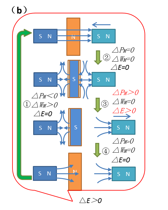
Now, consider the energy dynamics of the movable magnet in Figure 3c. During its motion, the movable magnet is subjected to intermittent electromagnetic forces from the fixed magnet due to the superconductor’s alternating magnetic shielding.
To elucidate the energy changes within the sealed chamber model, each step is analysed:
Step ①: As the movable magnet approaches both the superconductor and fixed magnet, the superconductor (in the normal state) provides no shielding. The magnetic potential energy (PM) of the movable magnet relative to the fixed magnet decreases (PM<0), while the fixed magnet exerts an electromagnetic force (F) on the movable magnet, performing work (WM>0) [8,9]. Consequently, the total system energy remains conserved (ΔE=0).
Step ②: The superconductor transitions to the superconducting state. While energy conversions occur between the permanent magnets and the superconductor, the total system energy remains conserved (ΔE=0).
Step ③: The movable magnet retreats from the fixed magnet. Its magnetic potential energy increases (ΔPM>0). However, due to superconducting shielding, the fixed magnet exerts no electromagnetic force (F=0), performing no negative work. Within the sealed chamber, energy conservation holds for the fixed magnet, superconductor, and ideal gas. The increase in the movable magnet’s potential energy leads to system energy non-conservation (ΔE>0).
Step ④: The superconductor reverts to the normal state. Though energy exchanges occur between the superconductor and the environment, the total system energy remains conserved (ΔE=0).
Summarising these steps, the Figure 3b model completes an operational cycle. The movable magnet gains magnetic potential energy in Step ③, while energy conservation holds for all other components. The results is that in system energy non-conservation (ΔE>0) over the cycle.
Since the model involves interactions between the superconductor and two permanent magnets (including thermal exchange with the environment), energy conservation is expected for the entire system. The observed energy gain in the movable magnet thus implies global energy non-conservation within the model.
2.4. Root Cause of Energy Non-Conservation in the Movable Magnet
The conclusion that the movable magnet’s energy is non-conserved may seem counterintuitive and warrants rigorous validation. Below, the analysis is expanded from multiple perspectives to confirm this result and explore its origins.
In static, current-free magnetic fields (conservative fields), where ∇×H=0, electromagnetic forces on permanent magnet dipoles are conservative (F=−∇(μ⋅B)), akin to gravitational forces. Energy conservation governs the conversion between kinetic and potential energy.
However, in Figure 3a, the Meissner effect’s intermittent shielding during phase transitions creates a time-dependent non-conservative field in the model’s right region. A permanent magnet or ferromagnet placed here experiences intermittent forces. If such an object moves cyclically under these conditions, the loop integral of the magnetic force along its path becomes non-zero (∮F⋅dL=0). By the loop theorem, this implies energy non-conservation in the system.
Critically, this does not contradict the energy conservation of the Meissner effect itself. Instead, leveraging the Meissner effect’s shielding capability, the model intentionally creates a non-conservative field by intermittently suppressing the fixed magnet’s field.
In Figure 3b, the movable magnet oscillates within this non-conservative field. The loop integral of the fixed magnet’s electromagnetic force (excluding counter-field work) on the movable magnet is non-zero. While energy conservation holds for the left portion of the system (including counter-field interactions), the total system energy (ΔE) fails to conserve due to the movable magnet’s energy gain.
Figure 3c replaces the movable magnet with a ferromagnet. Unlike Figure 3b, during Step ② (superconducting state), the superconductor generates no counter-field against the ferromagnet (transient induced fields during phase transition may briefly interact, but vanish once shielding is active). Post-phase transition, the ferromagnet experiences no residual fields. In Step ③, the ferromagnet retreats unaffected by magnetic forces, yet its magnetic potential energy (PM) increases. With no compensating energy loss, this results in system energy non-conservation (ΔE>0).
Figure 3d and 3e illustrate the non-zero work contributions of the non-conservative fields on the movable magnet and ferromagnet, respectively.
Figure 3f provides a contrast: relocating the movable magnet to the same side as the fixed magnet (without shielding) eliminates the non-conservative field. Here, the loop integral of F equals zero (∮F⋅dL=0), ensuring total energy conservation (ΔE=0).
Crucially, employing identical models and methodologies, magnetic field shielding or manipulation via ferromagnetic Curie phase transitions likewise enables temporal non-conservative field functionality. This facilitates non-zero work performance on corresponding ferromagnet displacements within such fields, yielding net work output from the system.
3. Concerns Regarding Energy Consumption During Superconducting Phase Transition
According to the reversibility of phase transitions, a superconductor conserves energy upon completing a phase transition cycle. However, practical implementation—such as manually heating or cooling the system—raises concerns about external work input to sustain the cycle. Additionally, the entropy principle suggests that heat naturally flows from high to low temperatures, implying external work is required for repeated heating/cooling. To address this, an adiabatic chamber containing an ideal gas is introduced, as shown in Figure 4.
In Figure 4, a fixed magnet is placed inside a cylindrical superconductor, both housed within an adiabatic chamber equipped with a piston. A ferromagnet replaces the movable magnet for clarity. Initially, the superconductor is in the superconducting state, and the piston is free. To transition the superconductor to the normal state, the piston compresses the chamber’s gas, raising its temperature. Conversely, retracting the piston to its free position lowers the temperature, reverting the superconductor to the superconducting state. Here, external work on the piston (positive followed by negative) nets zero over a full cycle. With no heat loss and energy conservation in the adiabatic chamber (per Figure 2a), the system achieves total energy conservation. This setup also serves as an experimental apparatus for the model.
To validate the model’s magnetic shielding dynamics—specifically whether the superconductor blocks the permanent magnets’ fields and whether the shielded magnets mutually influence each other—COMSOL simulations are employed. These simulations also assess whether the loop integral of the magnetic force on the movable magnet is non-zero, confirming the presence of a non-conservative field.
4. COMSOL Simulation of Superconducting Electromagnetic Distributions
COMSOL Multiphysics® is ideal for theoretical physics analysis, particularly in electromagnetics, with built-in formulations for Maxwell’s equations. The model employs the AC/DC “Magnetic Fields” module to simulate magnetic shielding dynamics. Parameters such as permeability, conductivity, and permittivity are conFigd to reflect the Meissner effect.
4.1. Simulation Model Workflow
The COMSOL model geometry is shown in Figure 5a. Key steps include:
Initial Setup: A fixed magnet is placed inside a cylindrical superconductor (optimized for shielding). The superconductor starts in the normal state, with the movable magnet positioned 52 mm away.
Movable Magnet Approach (0–5 s): The movable magnet moves along the negative x-axis at 10 mm/s, reaching 2 mm proximity.
Superconducting Transition (5–6 s): The superconductor transitions to the superconducting state.
Static Phase (5–8 s): The movable magnet remains stationary.
Retreat Phase (8–13 s): The movable magnet returns to its initial position at 1 cm/s. Reverting the superconductor to the normal state initiates the next cycle.
4.2. Physical Fields, Parameters, and Meshing
Figure 5b to Figure 5d illustrate the mesh generation, local refinement, and parameter settings, respectively. The simulation aims to model the magnetic field distribution and variations in the superconducting model. For the superconductor, only the superconducting state and normal state magnetic field distributions are simulated. Here, the normal state is modeled as a paramagnetic material, while the superconducting state is treated as a diamagnetic material with zero internal magnetic flux. This approach aligns with superconducting theory. Consequently, the physics field selected is "Magnetic Fields," which is suitable for simulating low-frequency electromagnetic fields.
The parameters are conFigd based on the lower critical magnetic field regions of Type I or Type II superconductors (e.g., NbTi). The relative permeability μ is set to approach 0, and the electrical conductivity is set to infinity. In COMSOL simulations of superconductors, the relative permeability cannot be set to 0 directly; instead, a very small value (e.g., 10-3, as used in superconducting shielding literature[3]) is assigned. The electrical conductivity is conFigd as 10⁵ S/m. In the normal state, the superconductor exhibits paramagnetic behavior, so the relative permeability is set to 1. Detailed superconducting parameters are shown in Figure 5d.
Both the stationary and moving magnet materials are set to the software’s built-in N54 (Sintered NdFeB). The surface magnetic flux density of the materials is conFigd to 0.2 T (the maximum magnetic field fully shielded by superconductors via the Meissner effect does not exceed 0.2 T). The surrounding environment is modeled as air.
COMSOL mesh size and precision significantly impact simulation accuracy. Although the magnetic field distribution in this model is robust to mesh resolution for qualitative analysis, mesh smoothing is applied near magnetic flux-concentrated corners (Figs 5b and 5c) to minimize errors. The model is dynamic, utilizing COMSOL’s parameterized sweep function with a cyclic time period of 13 seconds. This method sacrifices precise calculations at all scan points but effectively captures overall trends for systems with clear spatial characteristics.
4.3. Shielding Region Magnetic Flux Density and Lorentz Force Analysis
Simulation results in Figure 6 display electromagnetic field distribution clouds at six key time points. From 0–5 seconds, the superconductor is in the normal (paramagnetic) state, exerting no influence on the permanent magnets’ fields. The 5–6 second transition phase is excluded from analysis (as Type I superconductors exhibit abrupt phase transitions within narrow temperature ranges, e.g., 10-3 K). From 6–13 seconds, the superconductor enters the superconducting state, expelling internal magnetic flux (Φ = 0). The superconductor generates repulsive magnetic fields on its surface under the influence of the permanent magnets, consistent with the Meissner effect. Simultaneously, it shields both the stationary and moving magnets’ fields, forming distinct diamagnetic regions. For clarity, the moving magnet remains stationary from 5–8 seconds; at 8 seconds, it begins to move away, weakening the shielding field—a behavior aligning with the Meissner effect. The cloud diagrams match theoretical predictions.
Figure 7a replicates Figure 2d for structural clarity. Figure 7b’s components align with (a), where (b1)–(b3) denote superconducting/normal states. Magnetic flux modulus at Point 1 in (b) confirms near-zero shielding in the superconducting state (R1/R2 regions), validating complete flux expulsion. The full model independently shields both magnets’ fields.
Figure 7c1 and Figure 7c2 show the magnetic flux density modulus at Point 1 in Figure 7b1 and Figure 7b2, respectively. The curve values at R1 and R2 indicate that the magnetic flux density modulus at Point 1 is nearly zero in the superconducting state, demonstrating that the magnetic field in this region is almost completely shielded, consistent with theoretical predictions. For the complete model, the superconductor individually suppresses the magnetic fields of the two permanent magnets on either side.
Figure 7d illustrates the Lorentz force on the moving magnet: (d1)/(d2)/(d3) correspond to (b1)/(b3)/(b4), showing force equilibrium between the superconductor and stationary magnet. Figure 7d4, for an iron-core magnet, shows forces only in the normal state, vanishing in superconductivity—consistent with Figure 3c’s theory.
4.4.Simulation Conclusions
The simulation results demonstrate the electromagnetic field distribution and variations formed by the interactions among permanent magnets, superconductors, and ferromagnetic materials in the proposed models. They also depict the electromagnetic force curves experienced by the moving magnet. For conventional superconducting shielding models, the simulation outcomes align perfectly with superconducting shielding theory and electromagnetic superposition principles, validating the accuracy and reliability of the COMSOL simulation method for the Figure 2c model.
In Figure 7c1, the magnetic flux density modulus curve at Point 1 in the shielding region indicates that the magnetic field initially exists but vanishes over time, confirming the formation of a time-dependent non-conservative field in specific regions. Figure 7d4, illustrating the electromagnetic force on the ferromagnetic material, reveals that the force acts on the ferromagnet only when the stationary magnet’s field is present. After superconducting shielding, the force approaches zero, validating that the electromagnetic force loop integral in non-conservative regions is non-zero, leading to energy non-conservation in the ferromagnet.
5. Conclusions
Based on well-established theories—including superconducting phase transitions, the Meissner effect, energy conservation, and loop theorems—the study analyzes the energy variations in the proposed Figure 2b superconducting shielding model after verifying energy conservation in conventional shielding models.
By decomposing the system using electromagnetic superposition principles and isolating energy-conserving components, the analysis focuses on the remaining stationary and moving magnet components. The results demonstrate that the moving magnet’s energy is non-conserved, causing overall system energy non-conservation.
Theoretical analysis further identifies a time-dependent non-conservative field in the model, where the loop integral of the electromagnetic force on the moving magnet is non-zero. This non-conservative interaction disrupts energy conservation, a conclusion corroborated by COMSOL simulations.
The simulations confirm that:
Magnetic flux density clouds match theoretical predictions.
Magnetic flux modulus curves align with intermittent shielding hypotheses.
Electromagnetic force curves for the moving magnet correlate with intermittent force interactions.
These findings conclusively prove energy non-conservation in the proposed superconducting shielding model, challenging the absoluteness of energy conservation principles and prompting reevaluation of classical energy conservation laws in non-conservative electromagnetic fields.
6. Supplementary Experimental Setup
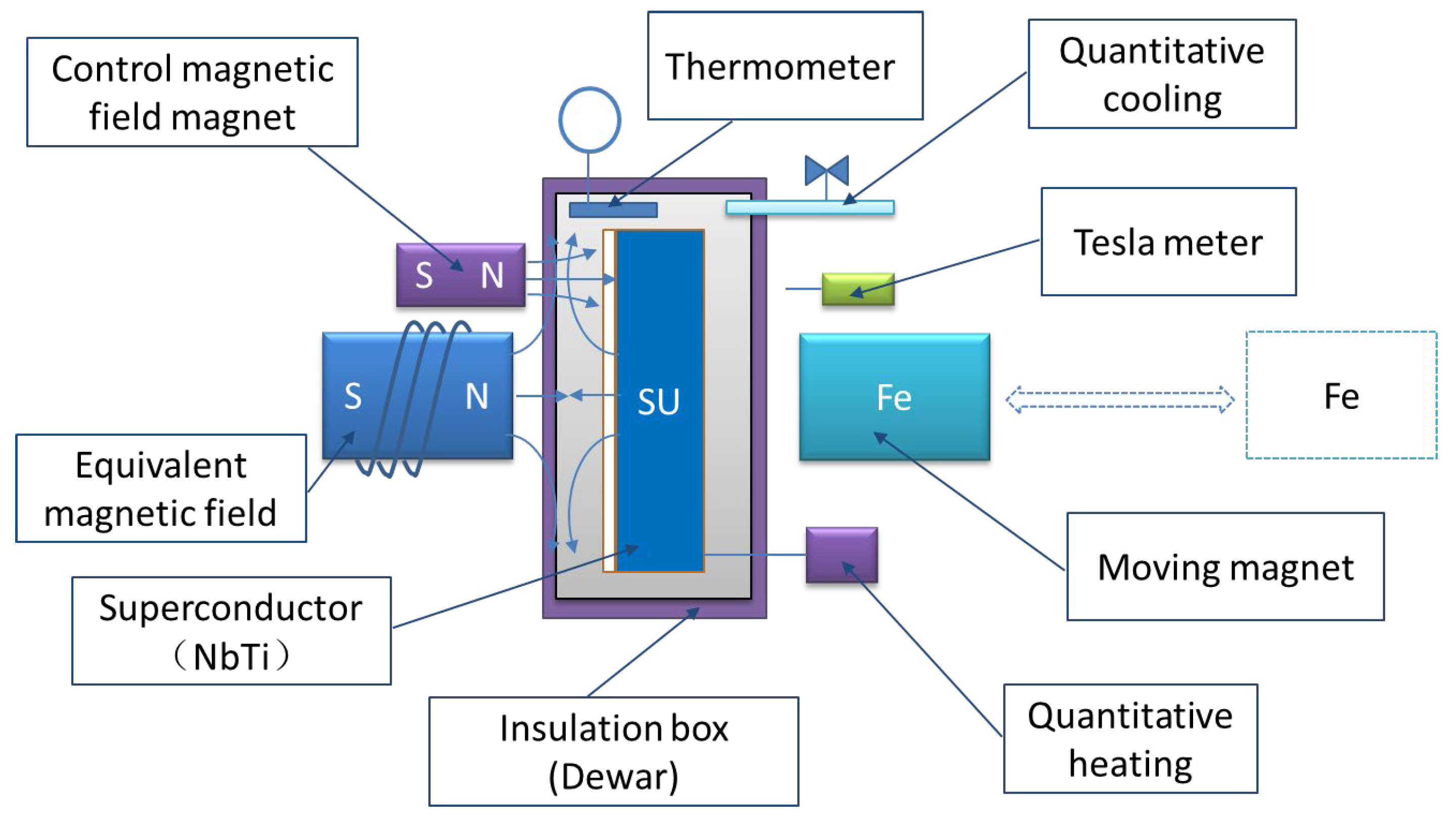
A proposed experimental apparatus (Figure 8) is described for verification. Due to the ultra-low-temperature requirements for superconducting experiments, practical implementation remains challenging at present.
Data Availability Statement
All the data is provided within the manuscript.
References
- Zhang YH. Superconducting Physics. Hefei: University of Science and Technology of China Press, 2009, pp. 31-36, 42-43.
- Zhao SW, Wang Haifei, Yang Xinrong, Wang Qiuliang. Electromagnetic Field and Energy Changes in Superconductors in the Meissner State under the Action of an Alternating External Magnetic Field. Journal of Low Temperature Physics, 2015, 37(1), pp. 66-69.
- Liu H. Research on Magnetic Shielding and Magnetic Transmission Properties of Superconductor-Ferromagnetic Metamaterials. Master's Thesis. Chengdu: Southwest Jiaotong University, 2015, p. 21.
- Hu XF. Simulation Study of Magnetic Shielding in Multilayer Shields Containing Superconductors. Master's Thesis. Changsha: Hunan University, 2015, pp. 1-66.
- Zhang WY, Zhang JF, Shi Le, Liu Donghui, Hu Xuefeng, et al. Simulation Study of Magnetic Shielding Properties in Multilayer Shields Containing Superconductors. Journal of Low Temperature Physics, 2017, 39(2), pp. 16-21.
- Wang ZC. Thermodynamics and Statistical Physics. Beijing: Higher Education Press, 2013, pp. 68-70.
- Yu L, Hao BL, Chen Xiaosong. Edge Miracles: Phase Transitions and Critical Phenomena. Beijing: Science Press, 2016, pp. 28-29.
- Hu YQ, Cheng FZ. Electromagnetism and Electrodynamics [Volume 2]. Beijing: Science Press, 2014, pp. 87-88.
- Guo SH. Electrodynamics. Beijing: Higher Education Press, 2008, p. 78.
Figure 1.
(a) Superconductor cooled first, then subjected to a magnetic field. (b) Superconductor field-cooled followed by field removal. (c) Superconductor field-cooled and reheated. (d) Common cylindrical superconductor configuration for shielding experiments to enhance effectiveness.
Figure 1.
(a) Superconductor cooled first, then subjected to a magnetic field. (b) Superconductor field-cooled followed by field removal. (c) Superconductor field-cooled and reheated. (d) Common cylindrical superconductor configuration for shielding experiments to enhance effectiveness.
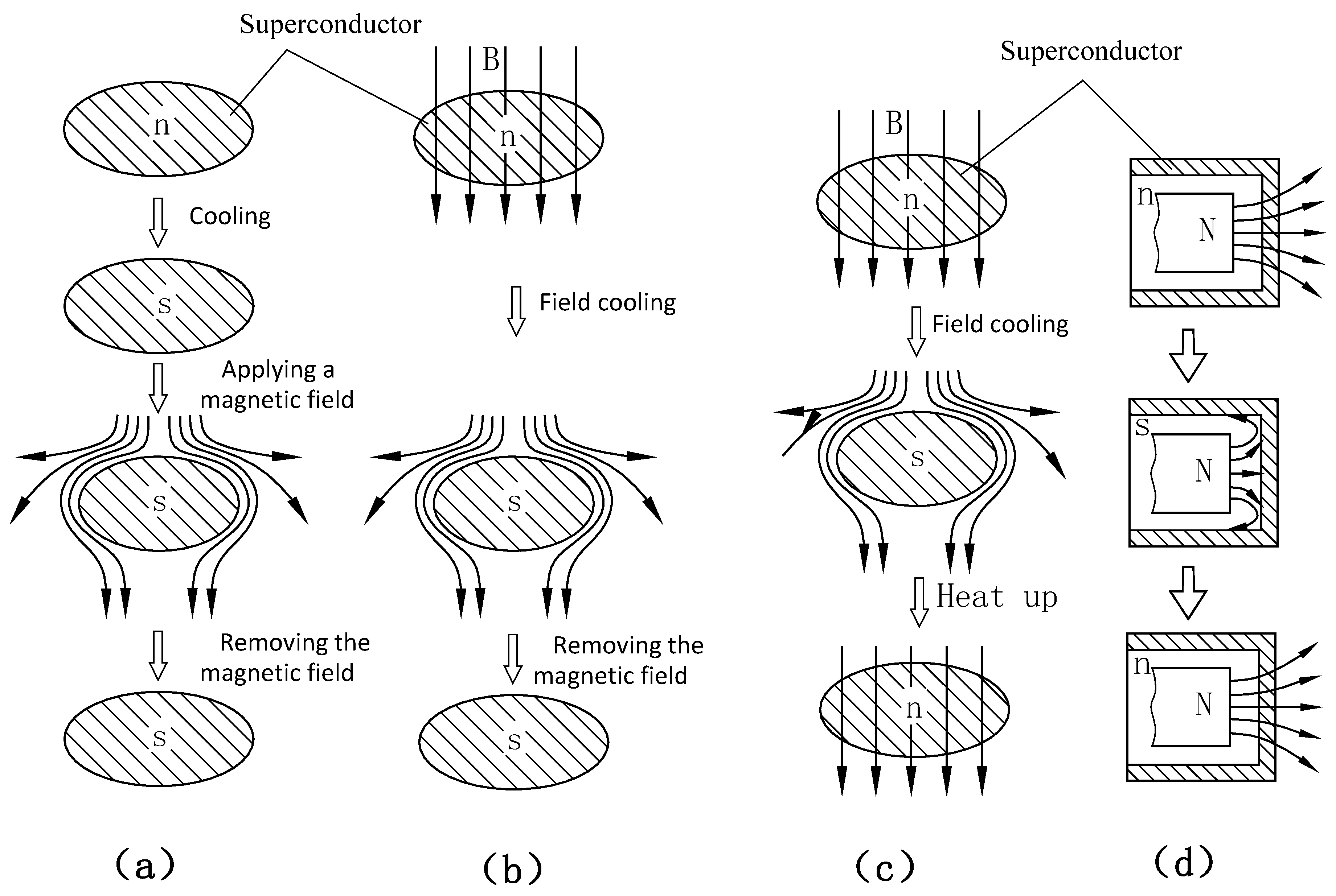
Figure 2.
(a) Model with a superconductor and fixed magnet; the superconductor completes a phase transition cycle in the fixed magnet’s field. (b) Model with a superconductor and movable magnet; the superconductor cycles within the movable magnet’s field. (c) Combined model (a + b) with fixed magnet, superconductor, and movable magnet. (d) Decomposition of (c) via electromagnetic superposition: (d1) represents (c); (d2) fixed magnet + superconductor; (d3) superconductor + movable magnet; (d4) fixed magnet + movable magnet. In diagrams: S = superconducting state, N = normal state; arrows indicate motion direction. △E=0 denotes energy conservation; E = total system energy.
Figure 2.
(a) Model with a superconductor and fixed magnet; the superconductor completes a phase transition cycle in the fixed magnet’s field. (b) Model with a superconductor and movable magnet; the superconductor cycles within the movable magnet’s field. (c) Combined model (a + b) with fixed magnet, superconductor, and movable magnet. (d) Decomposition of (c) via electromagnetic superposition: (d1) represents (c); (d2) fixed magnet + superconductor; (d3) superconductor + movable magnet; (d4) fixed magnet + movable magnet. In diagrams: S = superconducting state, N = normal state; arrows indicate motion direction. △E=0 denotes energy conservation; E = total system energy.
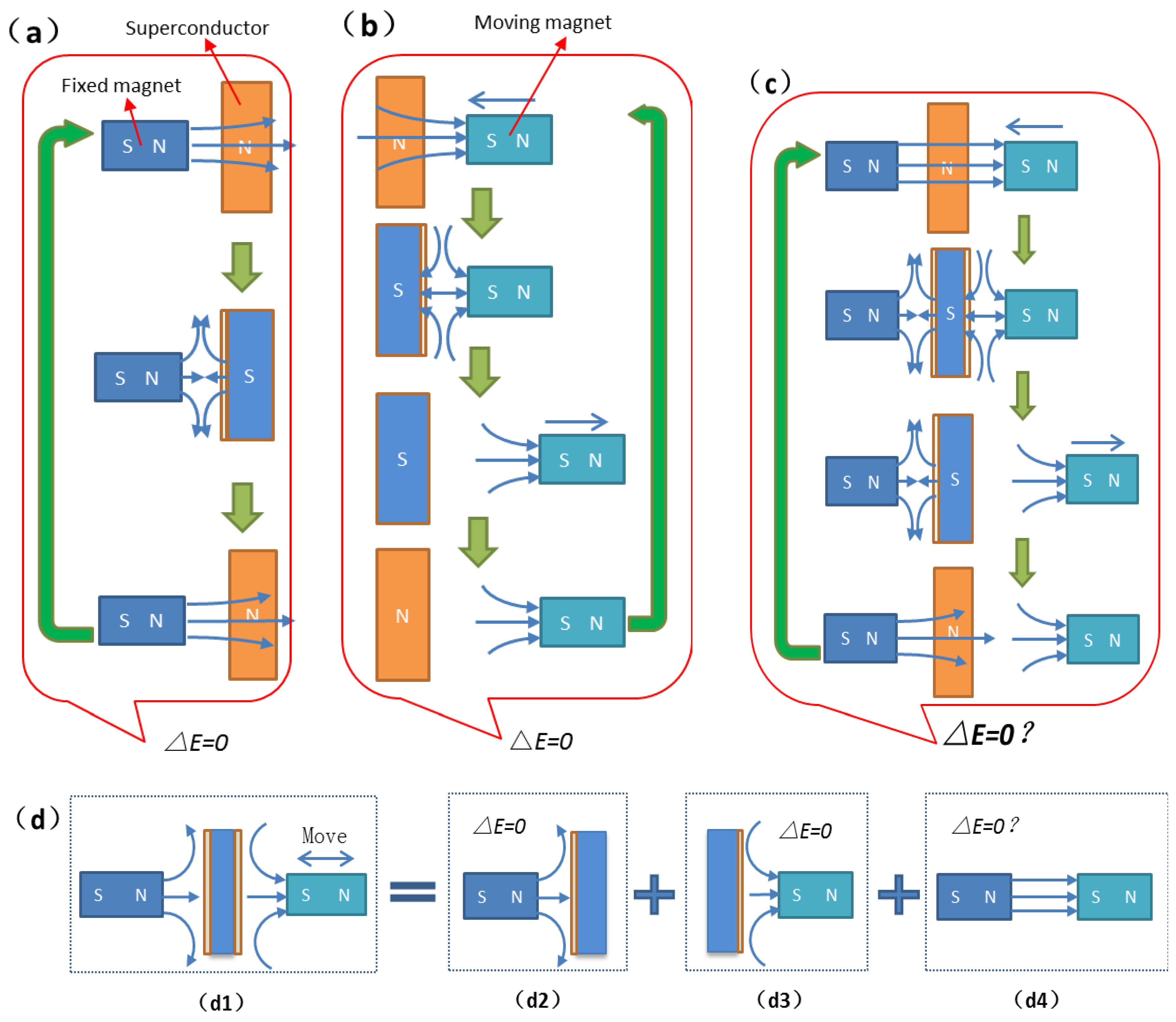
Figure 3.
(a) Cyclic superconducting phase transitions enable intermittent magnetic shielding, creating a time-varying magnetic field in specific regions. (b) Energy changes of the movable magnet in the Figure 2c model. (c) Replacement of the movable magnet with a ferromagnet in (b). (d) Non-zero loop integral of electromagnetic force (F) on the movable magnet in (b), leading to ΔE=0. (e) Non-zero loop integral for the ferromagnet in (c), causing ΔE=0. (f) Modified (b) model with the movable magnet positioned on the same side as the fixed magnet; without shielding, the loop integral of F equals zero, ensuring ΔE=0. Legend: PM = magnetic potential energy of movable magnet/ferromagnet relative to fixed magnet; WM = work done by fixed magnet’s magnetic force; F = electromagnetic force vector; L = motion path vector; △E = total energy change.
Figure 3.
(a) Cyclic superconducting phase transitions enable intermittent magnetic shielding, creating a time-varying magnetic field in specific regions. (b) Energy changes of the movable magnet in the Figure 2c model. (c) Replacement of the movable magnet with a ferromagnet in (b). (d) Non-zero loop integral of electromagnetic force (F) on the movable magnet in (b), leading to ΔE=0. (e) Non-zero loop integral for the ferromagnet in (c), causing ΔE=0. (f) Modified (b) model with the movable magnet positioned on the same side as the fixed magnet; without shielding, the loop integral of F equals zero, ensuring ΔE=0. Legend: PM = magnetic potential energy of movable magnet/ferromagnet relative to fixed magnet; WM = work done by fixed magnet’s magnetic force; F = electromagnetic force vector; L = motion path vector; △E = total energy change.
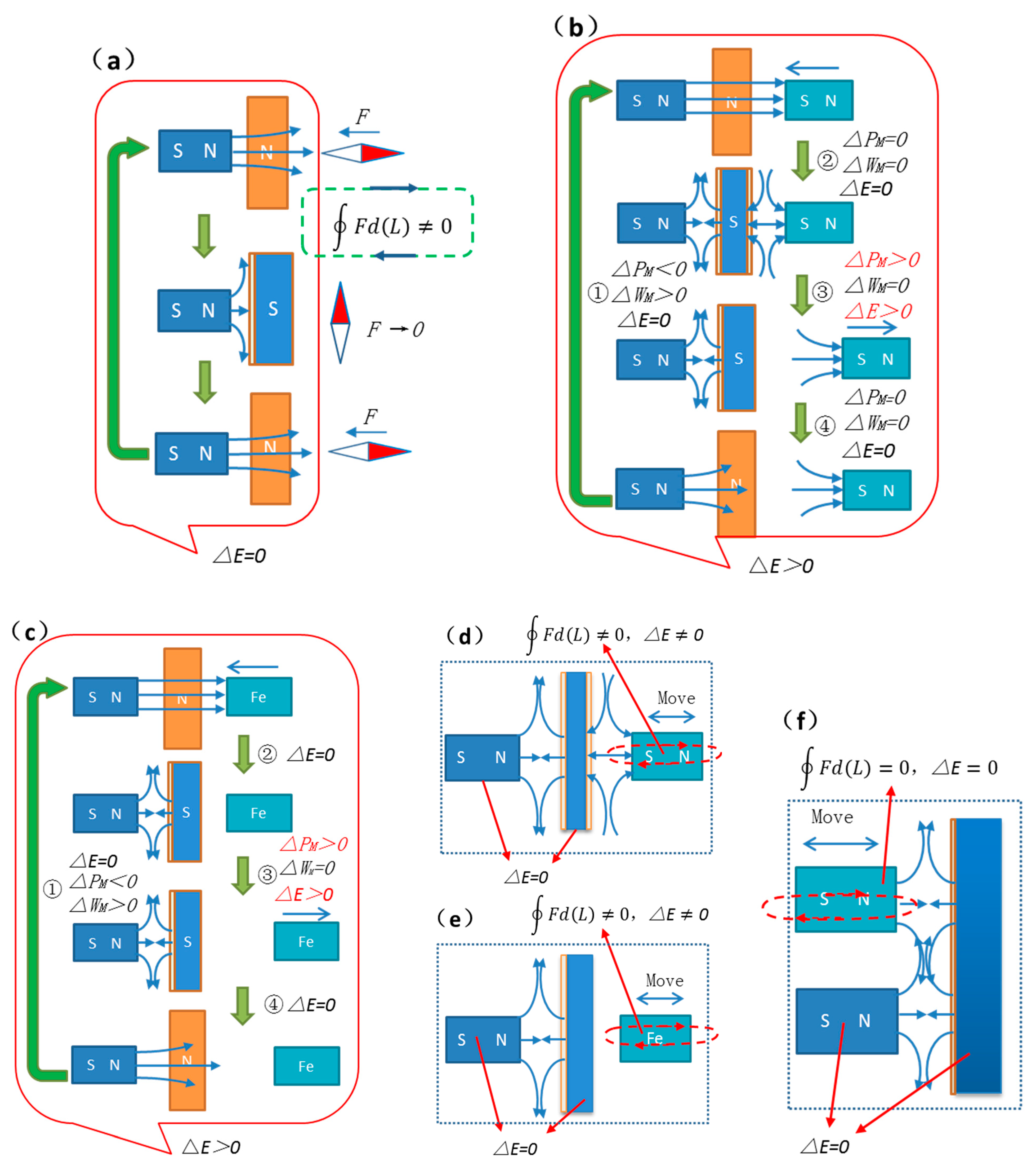
Figure 4.
illustrates adiabatic temperature control via a piston to enable superconducting phase transitions. All thermal exchanges between the superconductor and environment occur within the chamber, ensuring conservation of thermal energy, internal energy, and total energy.
Figure 4.
illustrates adiabatic temperature control via a piston to enable superconducting phase transitions. All thermal exchanges between the superconductor and environment occur within the chamber, ensuring conservation of thermal energy, internal energy, and total energy.
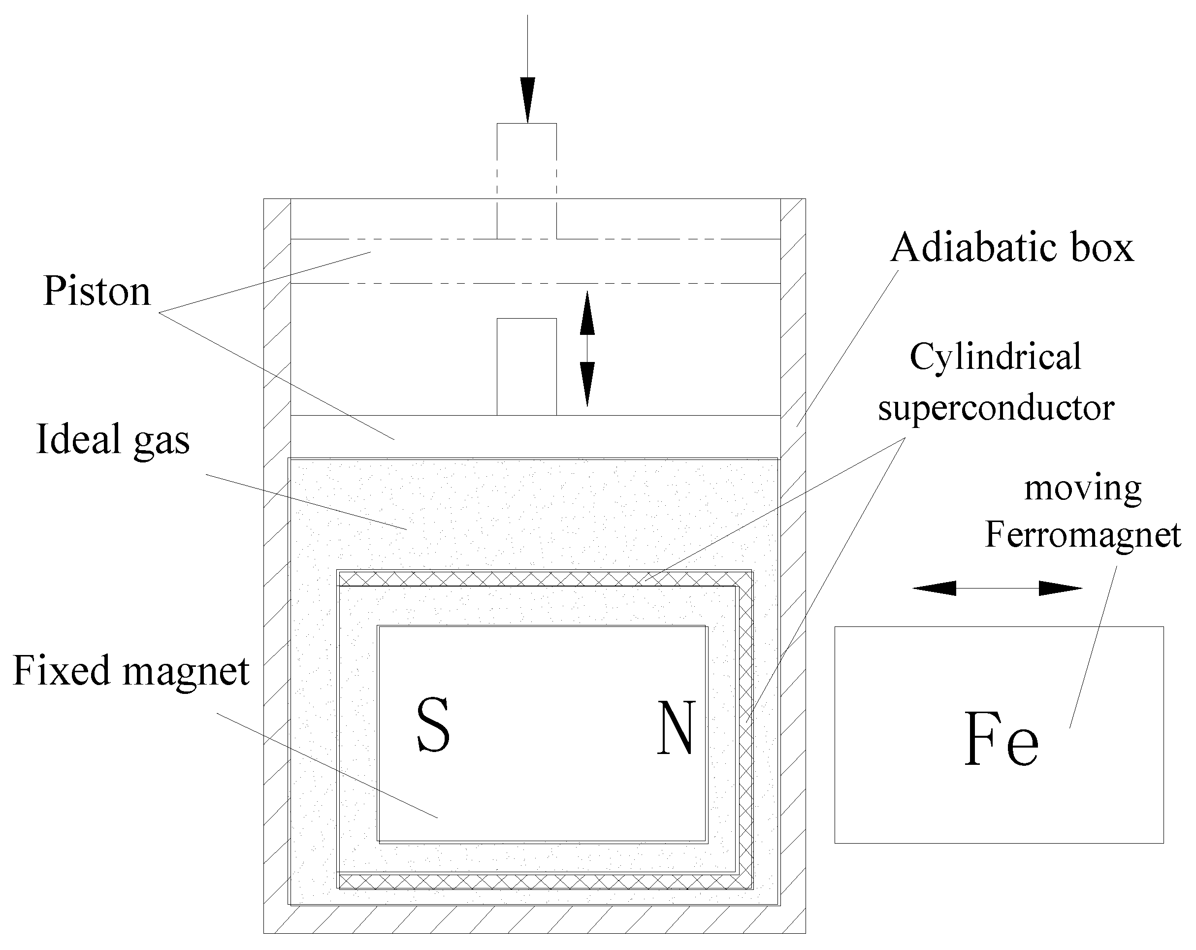
Figure 5.
(a) Geometry: Cylindrical superconductor, internal fixed magnet, and movable magnet along the x-axis. (b) Meshing of the model. (c) Mesh refinement in high-flux regions. (d) Physical field and parameter settings, including superconductor properties.
Figure 5.
(a) Geometry: Cylindrical superconductor, internal fixed magnet, and movable magnet along the x-axis. (b) Meshing of the model. (c) Mesh refinement in high-flux regions. (d) Physical field and parameter settings, including superconductor properties.
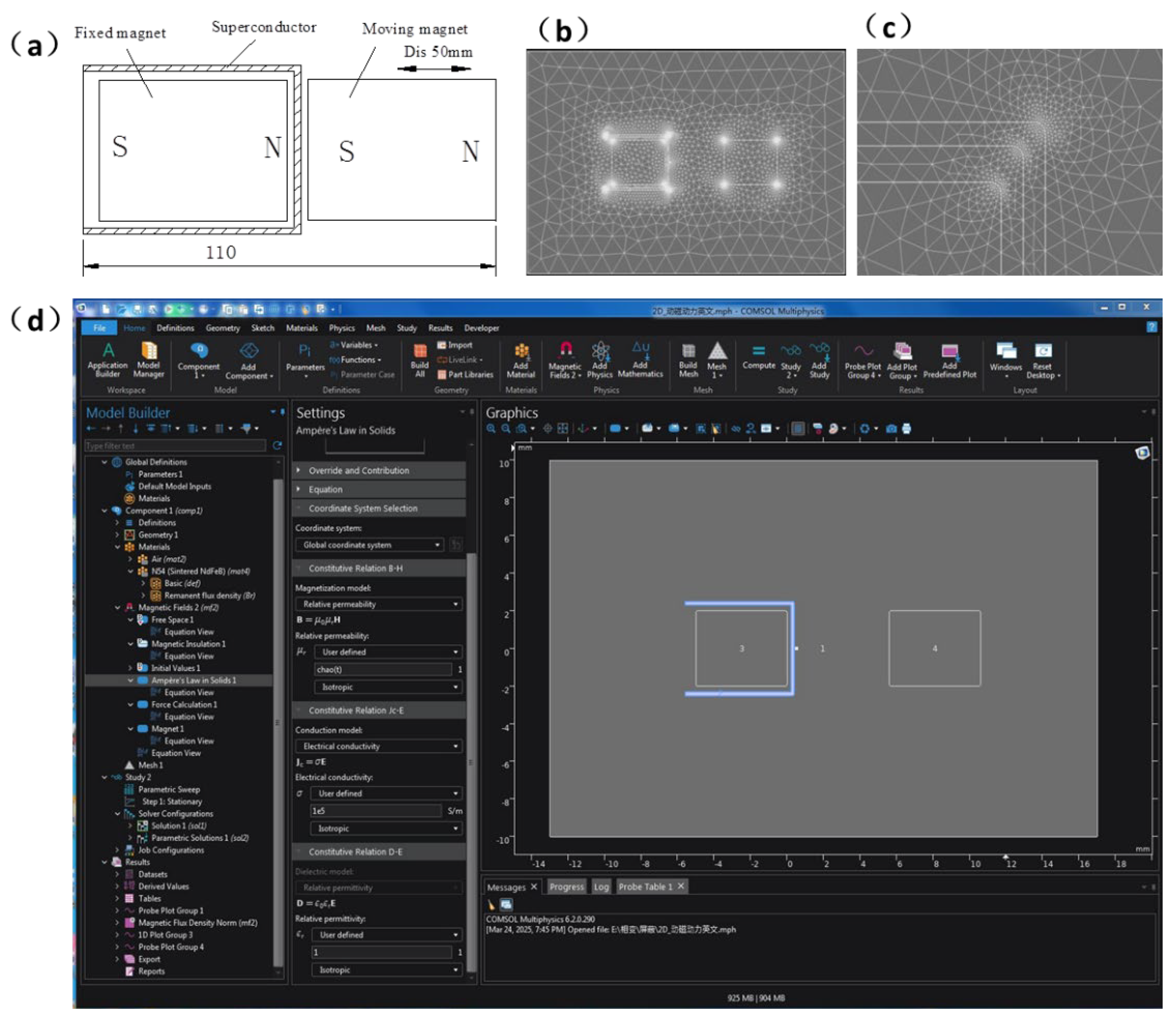
Figure 6.
Magnetic flux density distribution clouds at critical time points in the phase-transition cycle of the complete model (Figure 2c).
Figure 6.
Magnetic flux density distribution clouds at critical time points in the phase-transition cycle of the complete model (Figure 2c).
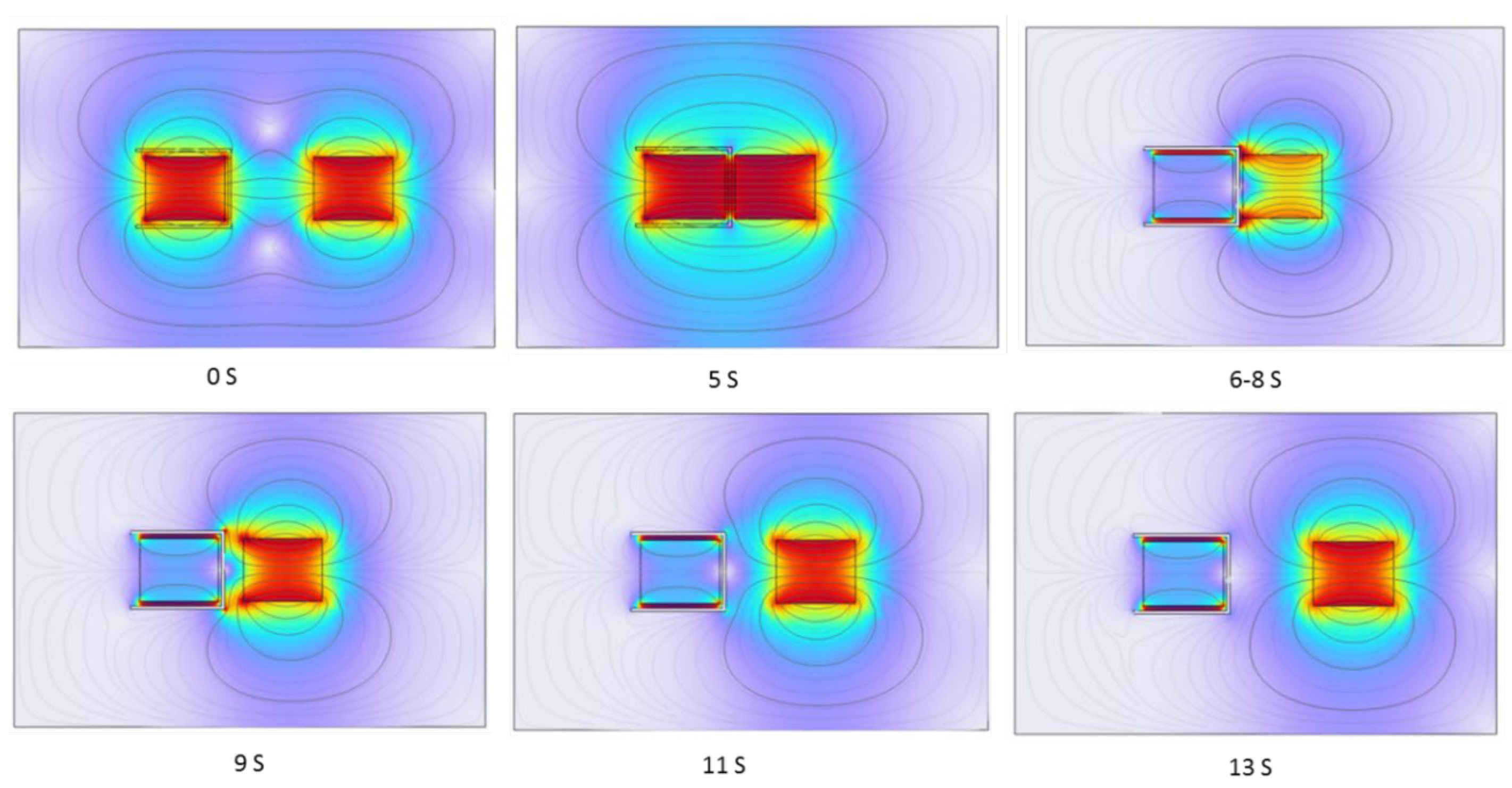
Figure 7.
(a) Replicates Figure 2d for structural correspondence. (b) Magnetic field distribution clouds: (b1) full model, (b2)/(b3) superconducting/normal states, matching (a). (c) Magnetic flux density modulus at Point 1 in (b), with (c1)/(c2) corresponding to (b2)/(b3). (d) Lorentz force on the moving magnet: (d1)/(d2)/(d3) correspond to (b1)/(b3)/(b4), while (d4) shows results for an iron-core magnet (Figure 3c).
Figure 7.
(a) Replicates Figure 2d for structural correspondence. (b) Magnetic field distribution clouds: (b1) full model, (b2)/(b3) superconducting/normal states, matching (a). (c) Magnetic flux density modulus at Point 1 in (b), with (c1)/(c2) corresponding to (b2)/(b3). (d) Lorentz force on the moving magnet: (d1)/(d2)/(d3) correspond to (b1)/(b3)/(b4), while (d4) shows results for an iron-core magnet (Figure 3c).
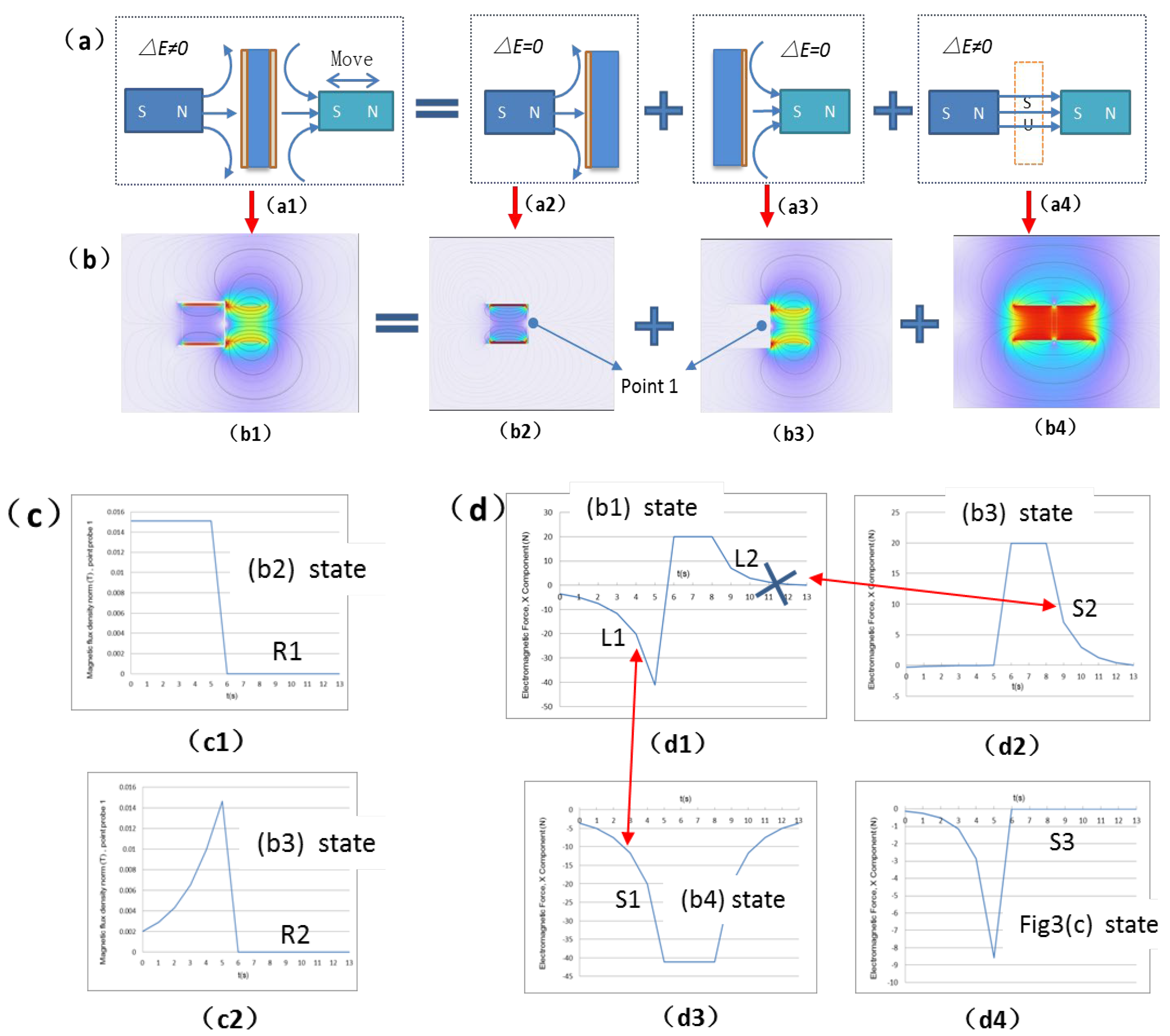
Figure 8.
Experimental setup for validation.
Disclaimer/Publisher’s Note: The statements, opinions and data contained in all publications are solely those of the individual author(s) and contributor(s) and not of MDPI and/or the editor(s). MDPI and/or the editor(s) disclaim responsibility for any injury to people or property resulting from any ideas, methods, instructions or products referred to in the content. |
© 2025 by the authors. Licensee MDPI, Basel, Switzerland. This article is an open access article distributed under the terms and conditions of the Creative Commons Attribution (CC BY) license (http://creativecommons.org/licenses/by/4.0/).
Copyright: This open access article is published under a Creative Commons CC BY 4.0 license, which permit the free download, distribution, and reuse, provided that the author and preprint are cited in any reuse.


