
Submitted:
30 September 2024
Posted:
03 October 2024
You are already at the latest version
Abstract
Wind-solar power generating and hybrid battery-supercapacitor energy storage complex is used for autonomous power supply of consumers in remote areas. This work uses passivity-based control (PBC) for this complex in accordance with the accepted energy management strategy (EMS). Structural and parametric synthesis of the overall PBC system was carried out that was accompanied by a significant amount of research. In order to simplify this synthesis, a structural decomposition of the overall dynamic system of the object, which was described by a system of differential equations of the seventh order, into three subsystems was applied. These subsystems are a wind turbine, a PV plant and a hybrid battery-supercapacitor system. For each of the subsystems, it is quite simple to synthesize the control influence formers, which locally perform the tasks set by the EMS. The results obtained by computer simulation of the overall and decomposed systems demonstrate the effectiveness of this approach in simplifying synthesis and debugging procedures of complex multiphysical systems.
Keywords:
wind-solar power generating system
; hybrid energy storage system
; battery
; supercapacitor
; passivity-based control
; structural decomposition
1. Introduction
The need for autonomous supply of electrical energy to consumers has led to the development of autonomous power generating complexes using renewable energy sources (RES) [1]. Considering the stochastic nature of energy generation from RES, it is advisable to combine in one complex different sources of energy generation that complement each other. The most common variant of such implementation is a wind turbine (WT) and a solar photovoltaic (PV) plant, the maximum generation capacities of which, as a rule, do not coincide, which is due to seasonal, daily and climatic factors [2,3]. In order to coordinate stochastic schedules of generation and consumption of electrical energy, it is necessary to use energy storage systems (ESS) in autonomous electric power supply systems. Among ESSs, the best performance indicators characterize hybrid systems composed of energy accumulators with different characteristics, such as electrochemical batteries (B) as high-energy devices and supercapacitor (SC) modules as high-power devices [4,5,6]. Despite the fact that modern batteries of the lithium group already have quite high specific values of both energy and power, the hybrid B-SC electric ESSs, as shown by recent studies, is characterized by a longer life and even lower cost than only battery systems of the same installed energy capacity [7].
The use in one system, for generating and accumulating of electrical energy, so many types of electrical devices with different principles of operation complicates the implementation of the control system. For this purpose, sufficiently complex classical control strategies and intelligent control strategies are used [8,9,10]. Recently, the port-Hamiltonian (pH) system representation has been used for mathematical modeling of the operation of such predominantly nonlinear dynamic multiphysical systems, as well as for the development of their effective passivity-based control (PBC) [11,12]. This approach is as close as possible to the real physical interpretation of the system, and individual subsystems connect among themselves by pairs of variables, the product of which is always a power [13]. A similar energy approach is used in the method of synthesis of the energy-shaping control system by introducing additional interconnections and damping assignment (IDA) [14]. Since the total energy of the synthesized system (Hamiltonian) in the steady state always has a minimum, such control always ensures the asymptotic stability of the nonlinear dynamic system.
In this work, the pH system representation and the IDA-PBC method are applied to a wind-solar power generating and hybrid B-SC energy storage complex. Considering the need for all components of the complex to work on a common DC-bus, they are connected to the latter through appropriate DC-DC converters, every of which has its control input. The presence of a redundant number of control channels enables the implementation of a number of tasks that are combined into an energy management strategy (EMS). In our previous works [15,16,17], the method of structural synthesis of the energy-shaping control system was developed using the IDA-PBC method in the MathCAD environment. This technique makes it possible to quickly determine all possible structures of control influences formers (CIF) that perform the EMS tasks and ensure the asymptotic stability of the entire dynamic system. However, further work on the development of a real energy-shaping control system consists of the study of the effectiveness and efficiency of the obtained CIF structures, as well as in their parametric synthesis. For this, it is necessary to conduct research on computer models of the studied systems implemented most often in the Matlab/Simulink environment. In the case of high-order pH system, such studies are complex, require significant simulation time, and their results depend on a subjective factor related to the researcher experience.
Considering the high, seventh, order of the system of differential equations that describes the operation of the autonomous electric power supply complex studied in this paper, and, as a result, the difficulties in the synthesis of the energy-shaping control system, the use of structural decomposition is proposed in the paper. This approach is known, in particular, it was used in the research of complex mechanical dynamic systems [18,19]. The mathematical apparatus used in these works is quite complex, and the resulting decomposed system does not have a clear physical meaning, since it was obtained only by mathematically solving of the problem. In work [20], the decomposition of a bilateral tele-operation system is virtually decomposed into two subsystems that perform different functions – the master and slave robots. This solution provides effective two-level passive remote control of the robot movement, but the mathematical decomposition procedure is also quite complicated. Since an advantage of pH systems is the possibility of structural modeling as close as possible to the physical implementation of the studied system, the simplest decomposition is the structural one related to the functional tasks of the subsystems [21]. This approach simplifies the decomposition procedure as much as possible and makes it possible to form a complex multiphysical pH system from functionally separated pH subsystems that minimally interact each other. This leads to a much simpler task of synthesis by the IDA method of several PBC subsystems of a lower order according to the set by EMS control tasks.
2. Materials and Methods
The functional electrical diagram of a wind-solar power generating and hybrid energy storage complex is shown in Figure 1.
Figure 1 shows that all the components of the complex – PV string, WT, B and SC-module – operate through their own DC-DC converters to a common DC-bus network with a constant voltage vbus on the capacitor Cbus. At the same time, the DC-DC1 and DC-DC2 converters are the single-quadrant, and DC-DC3 and DC-DC4 ones are the double-quadrant, due to the peculiarities of the operation of the generating and energy storage parts of the complex. The wind power plant uses a PMSG permanent magnet synchronous generator, the alternating voltage at the output of which is rectified by a diode rectifier and fed to the input of the DC-DC2 converter. The consumer of electric energy is modeled as an EMF Eload with an additional R-L link Rload, Lload, and is connected directly to the vbus voltage. Such a load can be either passive or active, depending on the ratio of the voltages vbus and Eload.
According to the diagram in Figure 1, differential equations were developed for each of the elements, which in general formed the following mathematical model of the object of regulation [15,16]:
where ui and ii are the voltages and currents at the respective generating and accumulating devices (indicated in Figure 1); Lb, Lsc, Ll, Lpv, Lw are the inductances at the inputs of DC-DC converters in channels of the B, SC-module, load, PV string and WT, respectively; Rl is the active load resistance; El is the back-EMF of load; μb, μsc, μpv, μw are the duty ratios of the respective DC-DC converters.
As mentioned above, energy-shaping control is based on the representation of the system from the energy perspective, so it is necessary to represent the control object as a pH system, which has the following description [11]:
where x(t) is the vector of state variables, J(x) is the skew symmetric interconnection matrix, R(x) is the semi-definite symmetric matrix of damping, H(x) is the system energy storage function (Hamiltonian), D is the diagonal matrix of inertias, G(x) is the matrix of input ports, u(t) is the vector consisting of input energy variables of the system, and y(t) is vector of output variables.
The elements of the state vector are traditionally the energy pulses of the seven energy storage devices present in the system [11,12]:
The corresponding diagonal matrix of inertia of the system is as follows:
Based on (1), the following vectors of input u and output y variables were formed:
Taking into account (3) and (4), the total energy function of the system is described by equation
and the vector of partial derivatives from H(x) takes the form
Taking into account (1) - (8), the remaining pH structure matrices of the system will take the form
3. Results
3.1. Energy-Shaping Overal PBC System Synthesis
3.1.1. Creating of Energy Management Strategy (EMS)
The energy management system is responsible for forming the task for the structural synthesis of the energy-shaping control system and reflects the requirements for the system in static and dynamic operating modes. For the wind-solar power generating and B-SC storage complex, it is advisable to formulate the energy management strategy with the following tasks:
- maintaining a given desired value of the DC-bus voltage at the set level when the power generation capacities of solar and wind plants change, as well as consumption by the consumer;
- maintaining the voltage of the SC-module at the desired value to ensure that it provides random processes of both discharging and charging under the influence of random disturbances in the generation of electricity from the sun or wind and changes in the load;
- ensuring smooth changes in the battery current (which will increase its service life) by entrusting the SC-module with the development of fast transients.
In accordance with the established EMS, the values of state variables in the desired exact equilibrium of the system will be described by the following vector
3.1.2. Structural Synthesis of the Overal PBC System
The IDA-PBC method generates the necessary control influences on the system to ensure the movement of the closed system to the desired equilibrium point. The desired equilibrium point of the system is formed by setting the steady-state values of the state vector (12) and is expressed by the desired function of total energy Hd, which acquires a minimum value at this point. The dynamics of a closed asymptotically stable PBC system is described by the following vector-matrix equation [14,15,16]:
where is a new vector of system state variables, the elements of which reflect the errors between the corresponding desired values and the current values of x of the system state vector, is the desired Hamiltonian of the closed PBC system.
The formation of the desired matricies of interconnections and damping of the system is carried out by adding additional interconnections and damping, which is described by the following equations:
where Ja and Ra are the correction matrices of additionally introduced interconnections and damping, respectively, which form the PBC.
In equations (14) and (15), the matrices Ja and Ra are square matrices of the seventh order, and the interconnection matrix Ja has all elements jjk filled skew symmetrically with respect to the zero diagonal, and the damping matrix Ra is completely filled with elements rjj along the diagonal.
The structural synthesis of the asymptotically stable energy-shaping control system was carried out according to the author’s methodology in the MathCAD environment based on equations (2) and (13). Taking into account the presence of 28 independent coefficients in matrices Ja and Ra the synthesis resulted in a large number of possible CIFs structures with different combinations of these coefficients, among which the simplest ones were selected for implementation. As an experience of such synthesis shows, the CIF structures should not contain more than three coefficients, otherwise the mathematical expression for the CIF will be too complicated for practical implementation. For example, among the additionally introduced damping, we obtained the next features: r11 has a complex implementation; r22, r44, r55 do not make any changes to the basic structure (without additionally introduced interconnections and dampings); r33, r66, r77 can be used to change the structure of CIFs. The effectiveness of the application of the selected CIFs structures was evaluated by simulating the operation of the studied system on a computer model in Section 4.
3.2. Synthesis of Structural Decomposed PBC System
It is expedient to decompose the overall PBC system into two subsystems – electricity generating and energy storage. This decomposition is caused, first, by the different functions of these two subsystems. Since the operation of the wind and solar power generating subsystems work independently, it is also advisable to separate their control systems. Combining the B and the SC-module into one subsystem is advisable due to their close cooperation and mutual complementarity – the B must take on smoothly changing and long-term loads, while the SC-module, on the contrary, should take on rapidly changing and short-term loads [16]. These subsystems interact with each other through the DC-bus voltage.
As it will be shown below, instead of one overall 7th-order pH system, the decomposition will result in one 5th-order pH subsystem and two more 2nd-order pH subsystems. The synthesis of the corresponding energy-shaping control subsystems will be carried out according to the same algorithm as for the overall system.
3.2.1. The pH Representation and PBC Synthesis of the Energy Storage Subsystem
The main vectors and matrices for describing the hybrid B-SC ESS as a pH system are as follows:
Based on (16) and (18), the total energy function of the subsystem, as well as the vector of its partial derivatives, are obtained as
The matrices of the pH structure of the subsystem, taking into account (1)-(2) and (16)-(21), are as follows:
The complete matrices of interconnections and damping Ja and Ra for this PBC system has fifth order. In contrast to the overall energy-shaping system, these matrices already have 15 independent additional interconnections jjk and damping rjk, which significantly reduces the number of possible CIFs for the ESS. In addition, we have already studied the effectiveness of the obtained CIFs structures for the B-SC subsystem in [16], which resulted in the following best CIFs structures:
3.2.2. The pH Representation and PBC Synthesis of the Wind Energy Generating Subsystem
The main vectors and matrices for describing the subsystem of electricity generation from wind energy as pH systems are as follows:
Based on (27) and (29) the total energy functions of the subsystem is described by the following equation:
The vector of the partial derivatives of the subsystem is as follows:
The matrices of the pH structure of the subsystem, taking into account (1)-(2) and (27)-(32), are as follows:
The complete matrices of interconnections and damping for the synthesis of energy-shaping control subsystem by the IDA-PBC method are as follows:
As a result of the structural synthesis of the energy-shaping control, it was found that the additionally introduced dampings rw11 do not change the basic structure, and the dampings rw22 can be used to change the structure of the CIFs. All of the possible additional interrelationships form CIFs structures that can be realistically implemented. However, their effectiveness of application requires research, which is presented in Section 4.
3.2.3. The pH Representation and PBC Synthesis of the PV Energy Generating Subsystems
The main vectors and matrices for describing the subsystem of electricity generation from solar energy as pH systems are as follows:
Based on (38) and (40) the total energy functions of the subsystem is described by the following equation:
The vector of the partial derivatives of the subsystem is as follows:
The matrices of the pH structure of the subsystem, taking into account (1)-(2) and (38)-(43), are as follows:
The complete matrices of interconnections and damping for the synthesis of energy-shaping control subsystem by the IDA-PBC method are as follows:
As a result of the structural synthesis of the energy-shaping control, it was found that the additionally introduced dampings rpv11 do not change the basic structure, and the dampings rpv22 can be used to change the structure of the CIFs. All of the possible additional interrelationships form CIFs structures that can be realistically implemented. However, their effectiveness of application requires research, which is presented in Section 4.
4. Discussion
The study of the obtained CIF structures and the finding of rational parameters of the coefficients of interconnections and damping were performed by simulating the operation of both the overall system and the structural decomposed system in the Matlab/Simulink environment. Figure 2 presents a general computer model of the studied complex, which is built in accordance with the functional electrical diagram shown in Figure 1. Two such models with different synthesized control systems were created – overall PBC system and structural decomposed PBC system, which are implemented in the PBC Subsystems. In the Reference Subsystem, time diagrams with test references of the wind speed, solar insolation and load EMF are generated.
The PV Array, Wind Turbine, Battery, Supercapacitor Module, and Permanent Magnet Synchronous Machine subsystems, as well as DC-DC converter subsytems are available in the new versions of the Simulink SimScape library and were used to compose the studied model. The parameters of the model components were chosen as follows.
PV array: overall power 3.35 kW, module American Choice Solar ACS-335-M, maximum power 334.9 W, open circuit voltage 49.9 V, short-circuit current 9 A, series-connected modules per string 10, parallel strings 1.
WT: Darrius type with three straight blades, rated power 5 kW, nominal wind speed 10 m/s, maximum value of the power coefficient 0.3514, optimum value of the tip speed ratio 3.765.
PMSG: rated power 5 kW, pole pair 32, stator phase resistance 0.88 Ω, armature inductance 3 mH, moment of inertia 20 kgˑm2.
Battery: type Lead-Acid, nominal voltage 120 V, rated capacity 100 Ah.
SC-module: SC type Maxwell BCAP1200, nominal voltage 2.7 V, rated capacitance 1200 F, equivalent DC series resistance 0.58 mΩ, series-connected capacitors per string 60, parallel strings 1.
DC-DC convertors: average model.
Parameters of other elements of the system: Lpv = Lsc = 1 mH, Cbus = 0,001 F, Lb = 5 mH, Lw = 0.1 mH, Lload = 2 mH, Rload = 1 Ω.
System references: V*bus = 312 V, V*sc = 140 V.
As shown by preliminary simulation studies, during the operation of the studied WT at the maximum power point (MPP), the following dependences of the rectified voltage and current of the PMSG on its angular velocity were obtained:
In turn, the studied PV array should also operate in the MPP. By comparing the points from the power graph with the current graph, the following dependencies were formed for the optimal values of the PV array current and voltage on the intensity of solar irradiation Ir at a panel temperature of 35°C:
The parametric synthesis procedure for the entire energy-shaping control system was a complex task, which included a series of simulation studies of various CIFs structures obtained as a result of structural synthesis. At the same time, the introduction of certain additional interconnections led to system instability, for example, the interconnection j37 showed a positive result in reducing the static error of vbus, but led to fluctuations in dynamic processes. Therefore, to offset this negative impact, the r77 damping was additionally introduced. As a result, the following most effective CIFs structures were obtained for the overall PBC system:
The coefficients were set at: j12 = 0.75, j23 = 1, r33 = – 0.03, j37 = – 0.1, r22 = – 0.02, j36 = – 0.09.
Parametric synthesis for subsystems was a simpler task compared to the overall system, but still required the selection of both the necessary interconnections and damping and the settings of the desired impact on the system. As a result, in combination with (25) and (26), the following most effective CIFs structures for structural decomposed PBC subsystems of energy generation were additionally formed:
The coefficients were set at: j12 = 0.75, j23 = 1, r33 = – 0.03, j pv22 = – 0.1, rpv22 = – 0.2, rw22 = – 3.
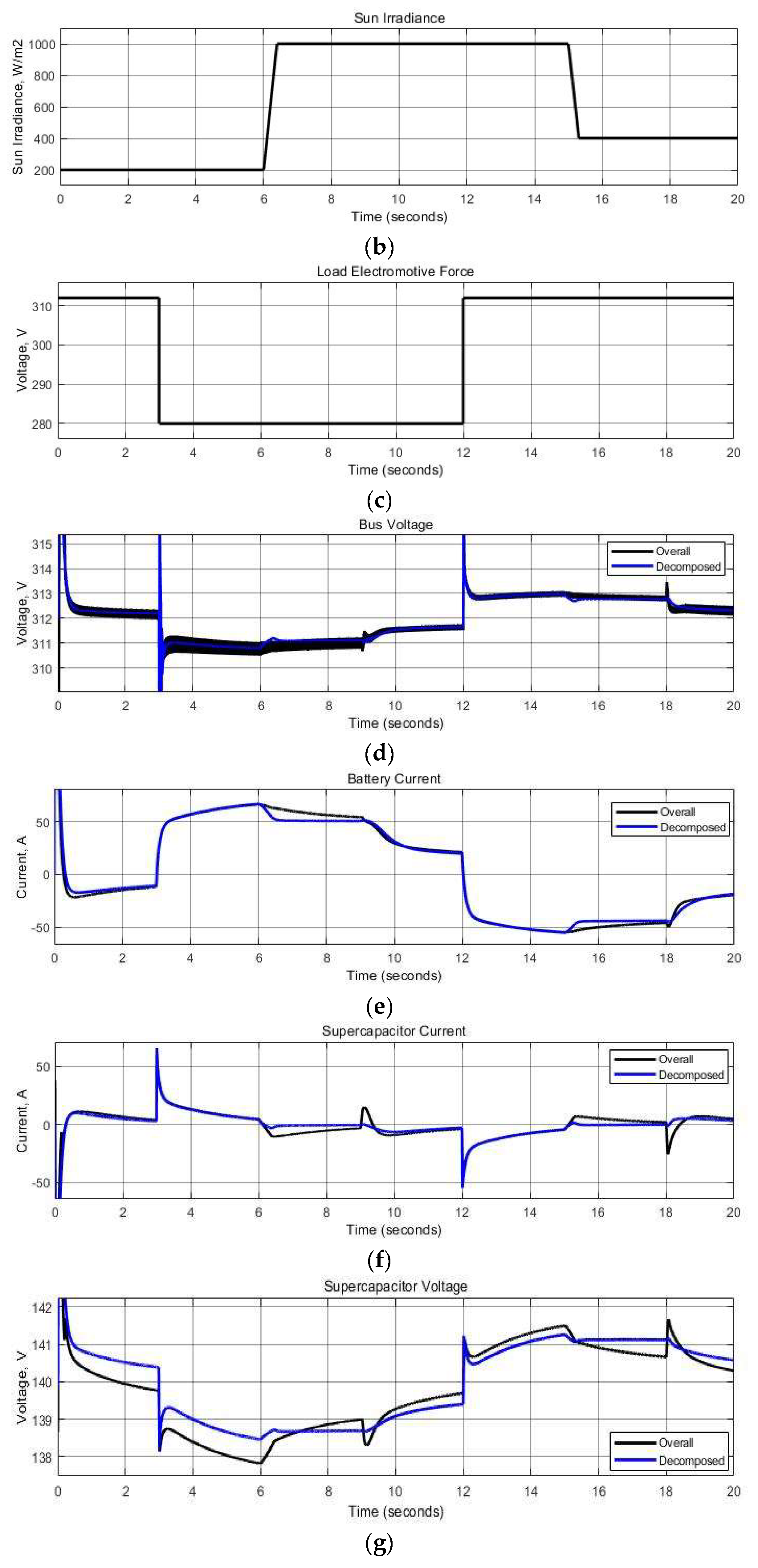
The results of the computer simulation of the operation of the overall and decomposed PBC systems are shown in Figure 3
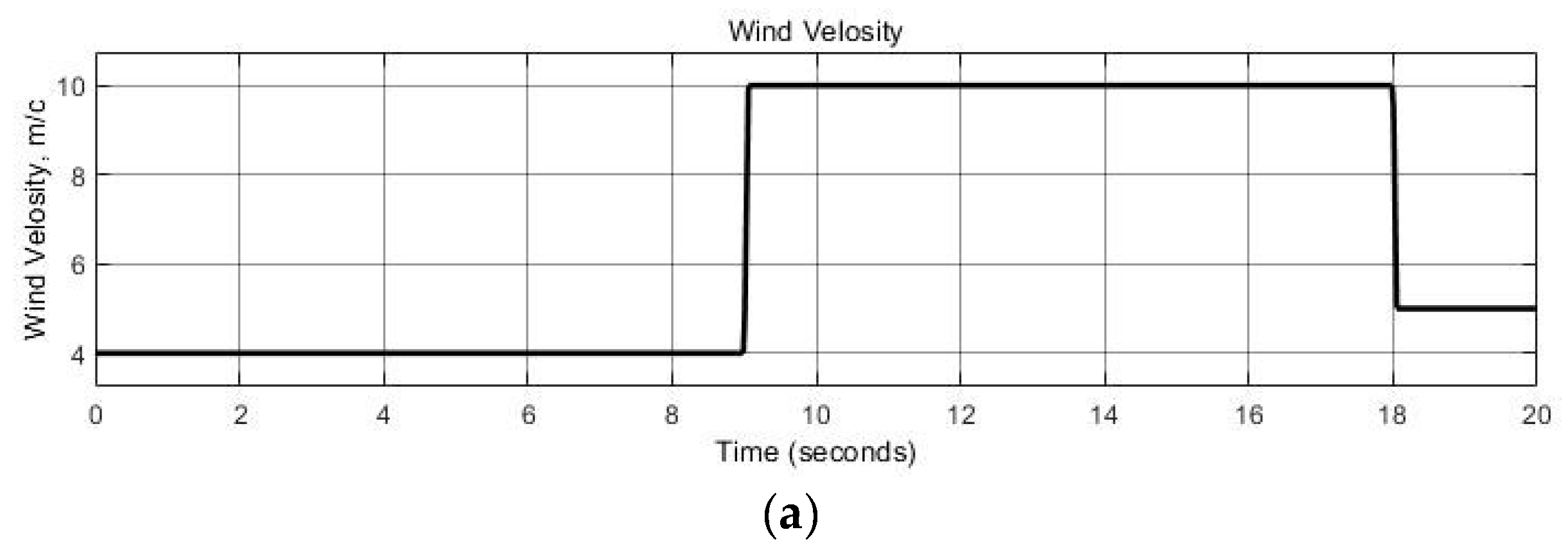
Time changes of the main disturbances in the system – the wind speed (Figure 3(a)), the solar irradiation intensity (Figure 3(b)), and the EMF load (Figure 3(c)), is modeled in such a way that it is possible to fully investigate the operation of the system under various combinations of these disturbances. The obtained results show that both systems respond similarly to the specified disturbances with minor deviations. From Figure 3(d), it can be noted that the overall PBC system is characterized by larger pulsations of the DC-bus voltage vbus, as well as by larger its dynamic responses to changes in wind speed and by smaller its dynamic responses to changes in solar insolation than for the decomposed system. However, the largest dynamic deviations of vbus in both systems occur with a sudden change in the load, since the interconnections between the load current and the ESS could not be fulfilled due to too complex mathematical dependencies of the obtained CIFs. Analyzing the time diagrams of the battery current (Figure 3(e)) and the SC-module current (Figure 3(f)), it can be seen that the overall PBC system provides a slightly smoother change in the battery current due to more intense changes in the SC-module current at times of rapid changes in wind and sun disturbances, which is explained by the action of the introduced corresponding interconnections. For the decomposed system, voltage stabilization on the SC-module is somewhat better (Figure 3 (g)).
5. Conclusions
Generally, hybridization performs the function of supplementing one means with others, which provides a certain positive effect. In this work, hybridization is applied to two main subsystems of the autonomous complex: the subsystem of electric energy generating from renewable sources of wind and sun, which increases the uniformity of the generated power, and the subsystem of electric energy accumulating in the battery and SC-module, which increases the lifetime of the battery. Mathematical modeling of dynamic processes in such complex multi-physical complexes should be carried out on an energy basis, representing the object as pH system, and automatic control of its operation should be implemented according to the principle of passivity – the PBC in accordance with the formed EMS. The principle of pH modeling is as close as possible to the physical implementation of the system and makes it possible to easily structurally combine individual simple pH systems into complexes. The reverse process is the structural decomposition of a complex pH system into simpler subsystems. If the conditions of the general EMS, which is being developed for the entire complex, can be divided between individual subsystems of a complex, then it is appropriate to synthesize individual PBC subsystems. In this work, this is shown on the example of the structural decomposition of the studied complex into three subsystems – two independently generating electricity, wind and solar, and one B-SC ESS. As shown in the work, this approach made it possible to significantly simplify the procedure for the structural and parametric synthesis of the PBC subsystems in comparison with the overall PBC system of the entire complex. The results obtained by computer simulation showed approximately the same quality of automatic control under the action of main disturbances from the both sides – energy generation and its consumption.
Author Contributions
Conceptualization, I.S. and M.L.; methodology, I.S. and R.-I.K.; software, I.S. and R.-I.K.; validation, M.L.; formal analysis, I.S. and M.L.; investigation, I.S. and R.-I.K.; resources, I.S.; data curation, R.-I.K.; writing—original draft preparation, I.S. and R.-I.K.; writing—review and editing, I.S. and M.L.; visualization, R.-I.K.; supervision, I.S. and M.L.; project administration, I.S. and M.L.; funding acquisition, M.L. All authors have read and agreed to the published version of the manuscript.
Funding
This research received no external funding.
Data Availability Statement
Not applicable.
Conflicts of Interest
The authors declare no conflict of interest.
References
- Muller, D. C.; Selvanathan, S. P.; Cuce, E.; Kumarasamy, S. Hybrid solar, wind, and energy storage system for a sustainable campus: A simulation study. STET 2023, 78. [CrossRef]
- Ravikumar, S.; Vennila, H. Hybrid Wind Solar System for Efficient Power Generation. In International Conference of Electronics, Communication and Aerospace Technology, Coimbatore, India, 20-22 April 2017. [CrossRef]
- Adetunla, A.; Rominiyi, O.; Adaramola, B.; Adeoye, A. Development of a wind turbine for a hybrid solar-wind power system. Heliyon 2022, 8. [CrossRef]
- Cabrane, Z.; Ouassaid, M.; Maaroufi, M. Analysis and evaluation of battery-supercapacitor hybrid energy storage system for photovoltaic installation. Int. J of Hydrog. Energy 2016, 41, 20897 – 20907. [CrossRef]
- Ma, T.; Yang, H.; Lu, L. Development of hybrid battery–supercapacitor energy storage for remote area renewable energy systems. Appl. Energy 2015, 153, 56–62. [CrossRef]
- Jing, W.; Hung Lai, C.; Wong, W. S.H.; Wong, D. M.L. A comprehensive study of battery-supercapacitor hybrid energy storage system for standalone PV power system in rural electrification. Appl. Energy 2018, 224, 340–356. [CrossRef]
- Ongaro, F.; Saggini, S.; Mattavelli, P. Li-Ion battery-supercapacitor hybrid storage system for a long lifetime, photovoltaic-based wireless sensor network. IEEE Trans. Power Electron. 2012, 27, 3944-3952. [CrossRef]
- Kollimalla, S. K.; Mishra, M. K.; Narasamma, N. L. Design and analysis of novel control strategy for battery and supercapacitor storage system, IEEE Trans. Sustain. Energy 2014, 5, 1137-1144. [CrossRef]
- Chong, L.W.; Wong Y.W.; Rajkumar, R.K.; Rajkumar, R.K.; Isa, D. Hybrid energy storage systems and control strategies for stand-alone renewable energy power systems. Renew. Sustain. Energy Rev. 2016, 66, 174–189. [CrossRef]
- Benaouadj, M.; Aboubou, A.; Ayad, M. Y.; Becherif, M. Nonlinear flatness control applied to supercapacitor contribution in hybrid power systems using photovoltaic source and batteries. Energy Procedia 2014, 50, 333-341. [CrossRef]
- Van der Schaft, A. Port-Hamiltonian modeling for control. Annu. Rev. Control Robot. Auton. Syst. 2020, 3, 393-418. [CrossRef]
- Bartel, A.; Clemens, M.; Günther, M.; Jacob, B.; Reis, T. Port-Hamiltonian systems modelling in electrical engineering. ARCXIV 2023, arXiv:2301.02024. [CrossRef]
- Nunna, K.; Sassano, M.; Astolfi, A. Constructive interconnection and damping assignment for port-controlled Hamiltonian systems. IEEE Trans. Autom. Contr. 2015, 60, 2350–2361. [CrossRef]
- Ortega, R.; van der Schaft, A. J.; Castanos, F.; Astolfi, A. Control by interconnection and standart passivity-based control of port-hamailtonian systems. IEEE Contr. Syst. Tech. 2008, 53, 2527-2542. [CrossRef]
- Shchur, I.; Biletskyi, Y. Battery Current Limitation in Passivity-Based Controlled Battery/Supercapacitor Hybrid Energy Storage System. In Proceedings of the 2018 IEEE 38th International Conference on Electronics and Nanotechnology, Kyiv, Ukraine, 24-26 April 2018. [CrossRef]
- Shchur, I.; Biletskyi, Y. Improved structure of passivity-based control of battery-supercapacitor hybrid energy storage system. Appl. Aspects of Inf. Tech. 2020, 3, 232-245. [CrossRef]
- Shchur, I.; Lis, M.; Biletskyi, Y. Passivity-based control of water pumping system using BLDC motor drive fed by solar PV array with battery storage system. Energies 2021, 14, 8184. [CrossRef]
- Höffner, K.; Guay, M. Decomposition of Linear Port-Hamiltonian Systems. In Proceedings of the 2011 American Control Conference, San Francisco, CA, USA, 29 June 2011 - 01 July 2011. [CrossRef]
- Lee, D.; Lui, K. Y. Passive configuration decomposition and passivity-based control of nonholonomic mechanical systems. IEEE Trans. Robot. 2017, 33, 281-297. [CrossRef]
- Cetin, K.; Tatlicioglu, E. A Passivity-based decomposing method for operational space control of kinematical redundant teleoperation systems. J. Cont. Engineering and Appl. Inf. 2021, 23, 41-49.
- Morandin, R.; Nicodemus, J.; Unger, B. Port-Hamiltonian dynamic mode decomposition. SIAM J. Sci. Comput. 2023, 45, A1690-A1710. [CrossRef]
Figure 1.
Functional electrical diagram of the wind-solar power generating and hybrid B-SC energy storage complex.
Figure 1.
Functional electrical diagram of the wind-solar power generating and hybrid B-SC energy storage complex.
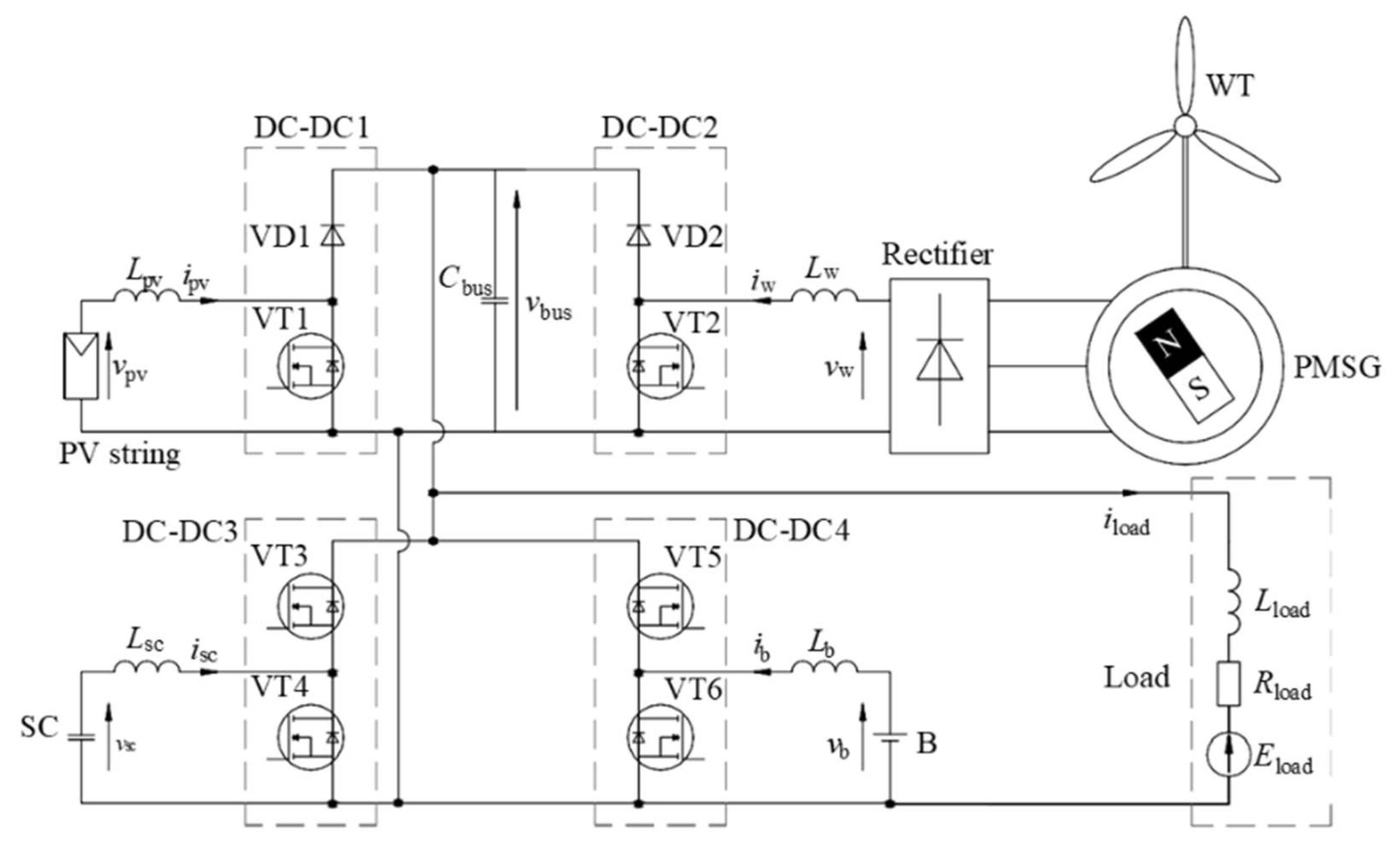
Figure 2.
General computer model of the studied complex wind-solar power generating and hybrid B-SC energy storage.
Figure 2.
General computer model of the studied complex wind-solar power generating and hybrid B-SC energy storage.
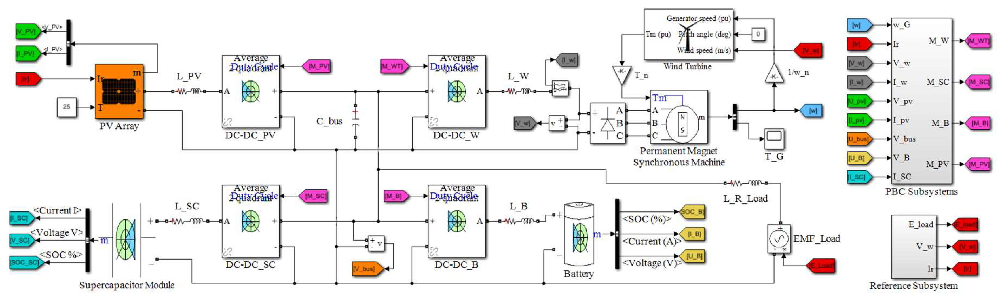
Figure 3.
Waveforms of main system variables obtained in simulation: (a) The wind speed; (b) The solar irradiation intensity; (c) The EMF load; (d) The DC-bus voltage; (e) The battery current; (f) The SC-module current; (g) The .SC-module voltage.
Figure 3.
Waveforms of main system variables obtained in simulation: (a) The wind speed; (b) The solar irradiation intensity; (c) The EMF load; (d) The DC-bus voltage; (e) The battery current; (f) The SC-module current; (g) The .SC-module voltage.
Disclaimer/Publisher’s Note: The statements, opinions and data contained in all publications are solely those of the individual author(s) and contributor(s) and not of MDPI and/or the editor(s). MDPI and/or the editor(s) disclaim responsibility for any injury to people or property resulting from any ideas, methods, instructions or products referred to in the content. |
© 2024 by the authors. Licensee MDPI, Basel, Switzerland. This article is an open access article distributed under the terms and conditions of the Creative Commons Attribution (CC BY) license (http://creativecommons.org/licenses/by/4.0/).
Copyright: This open access article is published under a Creative Commons CC BY 4.0 license, which permit the free download, distribution, and reuse, provided that the author and preprint are cited in any reuse.


