

Submitted:
27 September 2024
Posted:
30 September 2024
You are already at the latest version
Abstract
Technological advancements and evolving government regulations are driving the adoption of construction equipment powered by renewable energy sources, aiming to significantly reduce emissions. Electrifying non-road mobile machinery (NRMM), particularly self-propelled Rough-Terrain Variable Reach Trucks (RTVRT) with telescopic booms, presents stability challenges. Replacing diesel engines with electric motors and battery packs shifts the centre of gravity, necessitating precise load capacity determinations via load charts to ensure safe operation. This paper introduces a virtual model developed using multi-physic modelling with Bond Graph methodology. The model encompasses crucial components, including the chassis, rear axle, telescopic boom, attachment fork, and wheels, requiring three-dimensional treatment for spatial dynamics resolution. An illustrative example, supported by experimental data, demonstrates the model's capabilities. Special focus is placed on calculating ground wheel reaction forces and hydraulic self-leveling of the attachment fork. Numerical results validate the BG-3D simulation model of the telehandler with 20-Sim as a promising tool for estimating stability limits with satisfactory precision and predicting dynamic behavior across various operating conditions. Moreover, the paper explores potential extensions of the model, such as integrating the virtual vehicle model with a platform of variable inclination in subsequent phases which aims to evaluate telehandler longitudinal and lateral stability, aligning with the ISO 22915 standard and operator safety.
Keywords:
Telehandler
; Experimentation
; Simulation
; Dynamic Model
; Multi-solid
; Multi-domain
; Bond Graph
; Coupled Model
; Mechanics and Hydraulics
1. Introduction
The development of non-road mobile machinery (NRMM), particularly self-propelled Rough-Terrain Variable Reach Trucks (RTVRT) used for handling loads, equipped with a telescopic lifting means (pivoted boom), on which a load handling device (e.g. carriage and fork arms) is influenced by various factors ranging from customer needs to fuel prices and regulations. The original equipment manufacturers industry (OEMs) is rapidly shifting towards electric solutions due to stricter emissions regulations and high fuel costs. The use of internal combustion engines presents challenges in indoor applications and urban zones due to exhaust gases. Electrification & hybridization of these vehicles are seen as promising ways to reduce energy consumption and emissions.
Figure 1.
Telescopic machine. Source: AUSA.
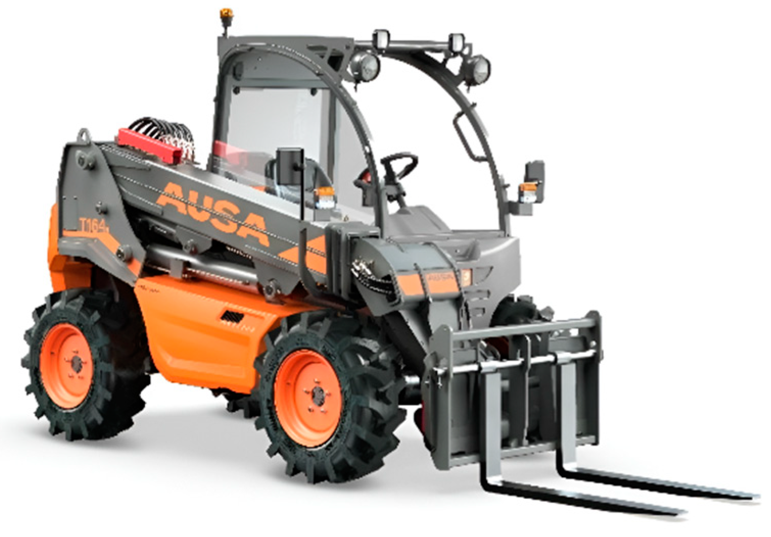
Telehandlers are highly versatile and powerful equipment that offer more capabilities than any other machinery on a construction and agriculture site. They have the ability to lift, scoop, remove, and push, making them comparable to other machines like forklift, skid steer loader, etc. One of the key factors contributing to their versatility is their maneuverability which allows for easy operation. Unfortunately, the same versatility that makes them so useful also provides room for unsafe usage, making ensuring their stability one of the most significant challenges. The vehicle stability in all operational conditions is a crucial challenge because it directly impacts the operator's safety. Because of this, it is remarkably interesting to quantify the degree of stability of the machine during its movement, how close or how far the machine is from losing stability, to know for example, its robustness against external disturbances when moving on uneven terrain, when climbing a ramp, when the arm raises and extended. Through computer calculations it is possible to know this stability degree and predict it while movement of the machine.
The need to electrify these machines imposes technical stability considerations on manufacturers, as the replacement of the diesel engine with an electric motor and a battery pack decisively influences the location of the centre of gravity. This, in turn, requires a comprehensive determination of load capacities (through the use of load charts for operators) to ensure safe and efficient performance. Load charts are crucial by providing accurate data of the maximum weight the machine can handle at various boom extensions and angles, considering changes in weight distribution caused by the electric components. With this idea, to evaluate the load charts of the telehandlers in the predesigns and design stages can be very important. This paper indicates how this type of information can be prepared in a non-experimental way, but in a virtual way obtained from results of numerical models.
The aspect of stability is of utmost importance, as indicated, highlighting the significance of this factor even in light of the existing international standards that address the safety requirements of telehandlers in terms of stability. [1] G. Priora (2019) summarizes the applicable regulations. The safety of machines in Europe is imposed by the Machinery Regulation (UE) 2023/1230 [2] and is deployed in multiple standards, among which EN/TS 1459-8:2018 [3], EN 15000:2008 [4], ISO 22915-14 2010 [5] and ISO 10896-1:2020 [6].
One of the main limitations of these standards is the fact that they do not adequately consider dynamic loads, such as inertia, which can jeopardize the machine's stability. Dynamic loads, caused by movements of the telescopic boom or sudden changes in load distribution, introduce additional forces and moments that can affect the stability.
Longitudinal stability refers to the stability along the machine's centreline, specifically its tendency to tip forward or backward. As the load handled increases or the boom extends, the longitudinal load moment increases, causing the rear axle to become lighter.
Lateral stability refers to the stability at right angles to the machine's centreline, specifically its tendency to lean sideways. When a load is lifted, the centre of gravity of the entire machine rises. This is not an issue if the machine is level; however, if the machine is on a slope, the centre of gravity will shift towards the tipping line as the load is lifted, causing a risk of tipping. Any attempt to turn will introduce additional centrifugal force that can result in a rollover.
All this is evidenced by data published by the HSE (Health Safety Executive of UK). The occupational health and safety laws that regulate the safety aspects of these vehicles are becoming increasingly stringent. Real data of HSE [7] demonstrates that the primary cause of instability and overturning in telescopic handlers is lateral, followed by longitudinal, identifying the risk factors associated with overturning accidents as says Figure 2.

Table 1.
(a) Longitudinal stability compromises; (b) Lateral stability compromises.
| Longitudinal Stability compromised by: | Lateral Stability compromised by: | ||||
|---|---|---|---|---|---|
| Action | Cause | Action | Cause | ||
| Load raising / lowering movement | Boom lifting / Extension | Gravitacional force | Load transportation | Vehicle bracking | Inertial force |
| Load lowering | Sudden boom braking | Inertial Force | Traveling on uneven surfaces | Potholes, bumps, ramps, slopes | Gravitacional / inertial force |
| Load transportation | Vehicle bracking | Inertial force | Specific eccentric loads | Gravitacional / inertial force | |
| Traveling on uneven surfaces | Potholes, bumps, ramps, slopes | Gravitacional / inertial force | Suspended load | Gravitacional / inertial force | |
| Suspended load | Gravitacional / inertial force | Wind | External force | ||
| (a) | (b) | ||||
Taking into account the aforementioned challenges, we deem it essential to create a comprehensive virtual model of the machine that is modular and customizable. As can be seen, inertial forces are the main cause of dynamic instability of this type of machines, which makes it very justifiable to use dynamic virtual models to study their stability. This model will enable us to optimize the weight distribution based on the requirements of electrification while prioritizing the safety of the operator and minimizing the potential hazards of overloading. In short, a virtual Load Chart of the machine that collects all the situations where the machine does not have rollover problems.
In this first paper, our objective is to introduce and showcase this virtual model based on a multi-physic modelling using Bond Graph methodology, emphasizing its suitability for the task at hand. We will focus on demonstrating its capabilities, deferring the specific study of stability to a subsequent paper.
2. Multi-Physic Modelling
As mentioned, stability evaluation is crucial when assessing the performance of telehandlers, and it has long been a subject of interest for researchers. Different methods, including theoretical calculation, virtual simulation, platform experiment, and road experiment, are used to evaluate stability, with each method having its advantages and connections to one another.
Figure 3 generically summarizes the interconnection of the different stages that can be followed in the design of mobile machinery. The ISO 22915-14:2010 [5] standard includes the experimental methods traditionally used to verify the lateral and longitudinal stability of telehandlers. It can be resource-intensive as it necessitates the construction of prototypes and test platform layout. On the other hand, theoretical calculation methods are often used in vehicle structure design but may have discrepancies compared to real-world situations [8] [9]. This approach often leads to a design methodology that is difficult to parameterize. Moreover, theoretical calculations tend to be heavily focused on the structural design of the vehicle. These factors culminate in a final product that is a compromise between real-world usability demands and the ambitious goals of the initially created prototype, Underscoring the need for a more advanced and efficient design approach.
In contrast, the virtual model paradigm, also known as digital twins, overcomes the limitations of theoretical calculation and replaces the need for validation and verification of a physical prototype. However, it is not only limited to simulating physical behaviour and haptic aspects. It can also provide information on aspects such as sensitivity to physical stability in extreme situations and energy efficiency measurements, among others.
Digital model paradigms, fundamentally based on multibody systems, are the design bases for future prototypes in the automotive world. However, the industrial world of NRMMs still adheres to more traditionalist design patterns, justifying the suitability of robust and durable design methods. Yet, the advantages of using virtual simulation are undeniable, and this work aims to demonstrate the confidence and potential these methods can bring to the field of mobile machinery design.
2.1. Mathematical Formulations and Multibody System Simulation (MBS) Software Platforms
A multibody system (MBS) consists of solid bodies connected to each other by joints that restrict their relative motion. The study of MBS involves analyzing how mechanism systems move under the influence of forces, also known as forward dynamics. The inverse problem, which examines the forces necessary to make the mechanical system move in a specific manner, is known as inverse dynamics.
Different formulations are available for modelling multibody systems. Among others, [10] G. Urkullu (2019) provides a comprehensive synthesis of the different formulations of the equations of motion. Applying Newton's laws is essential in analyzing multibody systems (MBS), as they are the foundation for formulating equations of motion. Different approaches for formulating these equations include the Newton-Euler, Lagrange, Hamilton, Gibbs-Apple and Kane's formulations. The Newton-Euler formulation considers all constraint forces acting on the system's bodies, resulting in more equations than unknowns, which can be inefficient. In contrast, Lagrange and Kane's formulations eliminate constraint forces using d'Alembert's principle, reducing the number of equations compared to the Newton-Euler approach. Kane's formulation is particularly well suited for systems with multiple bodies and non-holonomic constraints that are not explicitly time-dependent.
It is crucial to recognize that the choice of method is not arbitrary, but rather a strategic decision based on the specific characteristics and constraints of the multibody system being modeled. Researchers and engineers often select the most appropriate method based on the system's complexity, desired accuracy, computational resources, and available expertise, thereby shaping the course of the analysis. To meet the requirements of the simulation, the vehicle model should accurately calculate the driving behavior of the telehandler. This involves detailed modelling of the multi-domain system: mechanical properties (inertia, tire parameters, suspensions and stabilizers stiffness, if any) and hydraulic properties to simulate the hydraulic system's complexity effectively. When analyzing the coupling between hydraulic and mechanical states during telehandler movements, oscillating motions of the vehicle, particularly pitch and yaw oscillations, play a significant role because these oscillations induce movements in attachments, causing pressure variations and other effects on the hydraulic system. So, the multi-domain coupling between mechanics and hydraulics is determined.
Multibody system dynamics is a well-developed theoretical, computational, and applied mechanics branch. Daniel García-Vallejo et al. [11] demonstrated that multibody system dynamics comprises various thematic communities, focusing on its application in vehicle dynamics (initially focused on automobiles and, more recently, off-road machines). On the other hand, it is worth noting the abundance of simulation software available for the simulation of multibody system dynamics. The available codes exhibit various capabilities, including generating equations of motion in numerical or symbolic form. Some software provides numerical integration and simulation functionalities, while others offer graphical data input, animation capabilities, CAD connectivity, and signal data analysis.
Currently, the most efficient way to model complex and large mechanical systems is through the use of specialized mechanical system simulation software. These software programs enable engineers to create models of mechanisms within a CAD-like graphical environment by defining bodies, constraints, and forces. The software then automatically generates the mathematical representation of the system and performs simulations. One of the key benefits is its fast modelling and simulation capabilities, making it highly valuable for rapid prototyping and conceptual design validation. Engineers can create models based on their understanding of physical phenomena without requiring extensive knowledge of mathematical representations. The intuitive interface of the software enables easy description of mechanical system models. Additionally, the software is user-friendly and allows for straightforward modifications to the models. Moreover, the amount of data involved in the modelling process is manageable, ensuring efficiency in handling and processing the data. The primary disadvantage of using specialized software is the associated costs of acquisition and maintenance. These programs require specialized development knowledge and cater to niche markets, resulting in higher prices and limited competition.
Table 2 presents a comprehensive overview of the significant software tools that are specifically designed for multibody and multiphysics simulations. These tools play a crucial role in our field, and understanding their classification is essential for any researcher or engineer. Class A comprises of widely used, general-purpose programs for analyzing and simulating multibody systems. On the other hand, Class B software codes while still in the stages of continuous development and research, hold immense potential. Their current drawback is that they are not yet widely known or well-documented, but their future is promising.
2.2. Exemples of Software Aplications in Literature
H. Guo (2016) [12] investigated the lateral stability of telehandlers based on a multi-solid dynamic model. This virtual prototype was created using Adams software, classified as AG1. The study's main results were to determine the critical tipping angle and the critical sliding angle, concluding that sliding occurs before tipping. G. Altare and others (2012) also studied the vertical and lateral stiffness of the tire and showed that the plane's inclination is not especially significant. As an example of A-G2 type, G. [13] Altare and others (2012) present a simulation model of a telescopic handler with a fork, using Amesim software for 1D hydraulic modelling complemented using Virtual Lab for mechanical modelling, and it mainly focuses on the hydraulic system responsible for fork self-levelling. When multi-physics is the main purpose, Modelica is often the chosen language. Dymola is one of the platforms preferred to modeling due to its highly stable and fast differential algebraic equation solvers. A. Patil & M. Radle (2021) [14] explain the behavior of the electrification of a forklift using this paradigm.
3. Telehandler Modelling Using Scalar and Vectorial Bond Graph
Nowadays, self-propelled rough-terrain variable reach trucks (RTVR) used for load handling are complex multidisciplinary systems. Interdisciplinary methodologies supported by software are crucial for systematic development and analysis.
The Bond Graph, invented in 1959 by Prof. Henry Paynter, is a graphic language particularly suited for modeling multidisciplinary dynamic engineering systems [15] Borutzky (2010), The aim is the power flow through the modeling system. There are different rules to must be taken in account that the management and translation to useful mathematical equations has been made using graphical computer tools, like 20-SIM. As their results a complete multip-hysics and multi-domine RTVR could be produced. Figure 4 summarizes the main characteristics. Several symbolic software codes oriented to Bond Graph can be available. Among them, we can highlight: 20-sim™, Amesim™, Bonsim, Bondyn, Symbol2000, and Modelica. [16] Romero Rey G. (2005) thesis summarized them.
The essential feature of Bond Graph language is its ability to describe the energy topology of a model at an acausal level. Over alternatives such as Modelica or Simulink languages (block diagrams), Bond Graph paradigm allows one to understand the physics of the problem. This constitutes the physical level of the description contained in the Bond Graph representation.
BG enables all the model variables to be globally assigned and all the equations to be globally organized. The multi-Bond or vector Bond Graph technique [17] A. M. Bos (1986), is applied in multibody theory to create a dedicated multi-Bond Graph library. It expands on the traditional Bond Graph method, using vector bonds and transforming elements into multiports. By doing so, Bond Graphs can be effectively utilized for analyzing three-dimensional multibody systems. These systems are composed of many rigid bodies and flexible bodies. Therefore, compact representations of BG models are given in the form of vector BG or multi-BG. The ability to use models in a plug-and-play fashion gives the modeler a great advantage in the field of design and simulation.
However, kinematic and geometric constraints result in differential causality loops, and nonlinear velocity relationships lead to nonlinear junction structures. The acausal nature of tools like Dymola, or those with a Bond Graph input (e.g. 20-Sim or MS1), sets them apart from other object-oriented tools, like Amesim philosophy, which primarily relies on its causal feature as the main constraint when implementing new components.
[19] Karnopp (1976) proposes a procedure for constructing Bond Graphs using Lagrange equations. [17] Bos (1986) in his thesis developed Bond Graph models for 3D multibody systems and discussed how to derive the equations of motion from the Bond Graph in several different forms. [18] Tiernego and Bos (1985) present a modular approach based on Newton-Euler equations and Hamiltonian formalism. Different causality assignment procedures have also been proposed in the literature, see [20] Marquis-Favre and Scavarda (2002). Library models for a rigid body and for various types of joints have been provided by [21] Zeid and Chung (1992), [22] Cellier and Nebot (2005), [23] Zimmer, D. 2006, [24] G. Filippini (2007), [25] B. Boudon (2019) so that Bond Graph models of rigid multibody systems can be assembled in a systematic manner.
Considering the previous sections, there are numerous software options available for modeling multisolid systems based on Bond Graph methodology. We used the 20-sim program for the numerical solution and simulation of the proposed model for three significant reasons. First, we have accumulated substantial experience in recent years with the 1D and 3D Bond Graph methodology [26] De Las Heras and Codina (1997). As part of his thesis, one of the authors, Filippini et al. (2007), has developed a multiBond Graph library for multibody systems, focusing specifically on accurately representing 3D (see annexe 2). Various components tailored to multibody systems were created, enabling us to work with different reference frames and manipulate them through translations and general transformations, which will be applied in the telehandler modeling process. Secondly, 20-sim has the capability to simulate multisolid systems without the need for additional tools. It is an interactive tool where model entry and model processing are fully integrated, [20] Marquis-Favre et al. (2002). This means that already during model entry and editing, models can be checked on their consistency. Finally, there is also an economic reason. This type of software like 20-Sim tends to be very economically accessible programs for universities with educational licenses.
3.1 Telehandler Model (3D Bond Graph)
Most of the mechanical systems involved in the vehicle (platform _chassis, rear axle, telescopic boom & attachment and four wheels) require a three-dimensional treatment to solve their spatial dynamics. In this first paper, we have considered that two domains stand out in the machine under study: the mechanical part and the hydraulic part that drives the arm and attachments.
3.1.1. Mechanical Domain Modelling
Due to the complexity of them, the main system has been described as a composition of lower levels submodels. The lowest level in this hierarchy structure is always an equation model. The telehandler BG 3D model with 20-Sim has been assembled and it is presented at Figure 5.
- 1.
- Platform submodel;
The platform that supports most of the machine's components (chassis, cab, dashboard, engine, front axle, transfer case, oil reservoir, counterweights, drives, etc.) and serves as the articulation point for the telescopic arm. The front axle is also fixed to the chassis and directly connected to the two front wheels, which are the driving wheels (without a suspension system). It integrates the hydraulic power unit responsible for providing the force to raise and extend the arm with the load.
The rear axle is hinged around the longitudinal axis with respect to the chassis to ensure contact of the wheels with the ground. A double-acting piston is mounted, which allows steering and orienting the two rear wheels (without a suspension system).
On the other side, telescopic boom is composed of a fixed part articulated to the chassis and a movable or extendable part relative to the fixed part. This configuration creates the telescopic mechanism that allows the lifting and extension of the attachment. The attachment or accessory articulate at the end of the arm to grasp the load to be manipulated, such as a bucket, pallet forks, muck grab, or winch.
The platform submodel is shown in Figure 6 where the chassis part is modeled as a rigid body with a local coordinate reference frame (x, y, z) attached to the centre of mass and aligned with the inertia principal axes. It has mass m, and the following principal inertia moments: roll (Jr) respect to the body x-axis, pitch (Jp) respect to the body y-axis and yaw (Jy) respect to the body z-axis. Also, the rear axle submodel and two front wheels submodels are considered as spatial multibody systems. Here, the joint submodels are necessary to link them to the chassis. The joints are represented as flexible instead of rigid using a pseudo spring-damper system with elastic and damping constants. The flow and efforts actuating on the joints depend on the relative position and the relative orientation among the bodies. In order to link two rigid bodies at a given joint it is necessary to do some transformations (translations "T" and rotations "R") between the reference frames associated to each body. In this way, the state variables expressed at the centre of mass of each body are transformed to a local reference frame attached to the joint. A brief description of each of these basic 3D-BG elements models [24] Filippini and others (2007) is included in annex nº 1.
At this point, it is important to note that the platform submodel was initially designed as a single rigid body encompassing several elements. However, the internal structure is conceived in such a way that when we need to implement electric motorization, it can accommodate a variable spatial arrangement of several independent rigid body elements, including but not limited to the electric motor and batteries. This design approach will allow us to redistribute the masses appropriately from the very beginning, with the aim of optimizing the vehicle's stability.
- 2.
- Rear Axle submodel;
The rear axle of a telehandler is a crucial component that supports the rear of the vehicle. It is designed to work in conjunction with the front axle (inserted in the platform submodel) and the vehicle’s steering and drive systems. This ensures optimal performance, especially in challenging working conditions. The combination of the steering cylinder, pivoting axle, spindles, and knuckles allows the telehandler to handle heavy loads, maneuver effectively, and maintain stability on uneven or rough terrain.
The rear axle submodel is shown in Figure 7, and the steering system submodel is shown in Figure 8. In this latter figure, we can see the bond between the mechanical and hydraulic domains.
- 3.
- Tire submodel
In general terms, a tire can be represented as a nonlinear system with multiple inputs (such as slip quantities, angles, and load forces) and outputs (including longitudinal and lateral forces, and tire moments), as illustrated in Figure 9. To describe the "black box" that links these inputs and outputs under (quasi) steady-state and non-steady-state conditions, various methods have been proposed, one of which is Pacejka's Magic Formula Tire model [27].
- 4.
- Telescopic arm system;
The telescopic boom of a telehandler consists of two main parts: a fixed section that pivots on the platform using a lifting cylinder, and a telescopic section controlled by an extension cylinder within the boom itself. The fixed section provides the base for vertical movement, while the telescopic section extends and retracts to adjust the reach of the telehandler. At the end of the boom, there's a mounting point for attachments like forks or lifting hooks, which moves with the boom's rotation, powered by a tilt cylinder. In Figure 10, the submodel of the telescopic arm configured from basic 3D-BG elements are shown. Here, each of the mechanical cylinder submodels (yellow boxes) is configured based on the structure shown in Figure 11.
To ensure stability during operation, a self-leveling system is included between the platform and the fixed boom section. This system uses a slave cylinder connected to the tilt cylinder to keep the attachment level with the ground, regardless of boom's movements.
3.2 Hydraulic Domain Modelling
The modelling of the hydraulic systems configuring the telehandler, referred to as the hydraulic domain, can be accurately performed using basic Bond Graph elements. These elements are characterized by 1D bonds that are defined by two scalar variables: the effort variable, which represents pressure, and the flow variable, which represents flow rate.
In a telehandler, we can distinguish three hydraulic subsystems: the rolling transmission subsystem, the steering subsystem, and the arm/implement drive subsystem. However, in this paper, we will only consider the implement drive subsystem of the boom/fork assembly given that it decisively affects the dynamic behavior of the machine. The basic schematic is shown in Figure 12. In this diagram, we highlight the following basic components: the pump group represented by the pump and a pressure relief valve, the open-centre directional control valve (two-spool), a valve block which can be referred to as a safety block, and the hydraulic cylinders responsible for the lifting, extension, and tilting.
To be as clear as possible, we have decided to explain the modelling process only for the circuit corresponding to the lifting movement of the arm, considering that the others are very similar and explaining them all would be redundant. The corresponding Bond Graph schematic is shown in Figure 13. In this figure, we highlight the Bond Graph diagram of the hydraulic cylinder, in which two transformer elements, TF, are used: one converts pressure and flow rate to linear motion and force (representing the chamber connected to the pressure line), and the other converts linear motion and force to pressure and flow rate (modelling the connection of the chamber to the return line). The 1-junction represents coupling where all flows of the connected bonds are equal. The submodel "end stop" aims to represent the contact forces when the piston comes into contact with the guide plug or the cylinder cap. The modelling also includes the compressibility of the fluid in the two cylinders chamber, the effects of friction (both Coulomb and viscous), and the inertia due to the moving mass of the cylinder piston and rods. Finally, the equivalent load is simulated as a negative effort (force) exerted at the cylinder rod tip from the boundary. The flow variable in this bond denominated "hydraulic port" is the rod velocity, which connects with the 3D Bond Graph of the mechanical domain that simulates the hydraulic cylinder actuating the boom (see Figure 13 and Figure 14).
We also want to highlight the inclusion of a load-holding valve in this circuit, also known as an overcentre valve, and its corresponding check valve. Load holding valves are used with cylinders to safely hold suspended loads and manage over-running loads.
Figure 14 shows in detail the generic Bond Graph of an overcentre valve, which is customized for the case of the valve CEB1 with atmospheric drainage. Here, the most significant parts, are the four MTF elements, that transform the effect of pressure on the different effective sections of the poppet into forces that combine at the 1-junction, the "flow forces" submodel (momentum conservation theorem) and forces due to spring compression have been included [28]. The 1-junction represents a force-balance and is a generalization of Newton’s third law. From here, we can determine the kinematic variables of the shutter and, consequently, deduce the relative position using the internal geometry of the valve.
Since the relative position between the poppet and its seat defines a passage section, we can calculate the flow rate through it by applying Bernoulli's equation. The discharge coefficient has been used here as an empirical correlation, a function of the Reynolds number and the geometry of the passage section defined by the relative position. This is included inside of "orifice" submodel [29].
As mentioned in a previous section, the lift and tilt actuation are managed by two 6-way 3-position mono-block directional valves. In the neutral position, both valves connect the pump port to the tank port. If either valve shifts from neutral, the pump disconnects from the tank. This configuration can be represented by combining orifices with variable area (metering) and a check valve block. When the valve is neutral, all orifices overlap except . These two orifices start the simulation with an opening offset (underlapping), allowing the pump to deliver low-pressure flow to the tank. Figure 15 illustrates the basic connection diagram, while Figure 16 shows the Bond Graph diagram, highlighting the different metering sections between ports P, T, A, and B and its control. The flow rate through the metering orifices depends on the opening area and the pressure drop across the valve. If ΔP is the pressure drop and A(x) is the metering section area (based on spool position x), the volumetric flow rate Q can be calculated as, where Cd is the discharge coefficient. The discharge coefficients are derived from fitting a quadratic polynomial to the experimental data of pressure drop versus flow rate, according to the methodology presented (Borghi) [30].
4. Experimental Test
After the construction of the model, it is imperative to subject it to rigorous validation, a crucial step that entails testing its performance against real-world data. This validation process typically involves evaluating the model's response to empirical data and scrutinizing its accuracy in comparison to observed values.
While inertial and geometrical parameters of the mechanical system, including the hydraulic actuator components, can be readily obtained from the CAD model, other parameters pose greater challenges. For instance, the elasto-damping parameters of the tires and, particularly, verifying specific parameters of the hydraulic system and its components can be more elusive.
In the mechanical domain, we utilized software tools such as Siemens-NX and Catia v6, made accessible through educational licenses provided by the UPC. Our telehandler model, consisting of 22 rigid bodies, was methodically constructed using suitable kinematic joints. Firstly, we established the global parameters for each solid. This involved defining the xyz coordinates of the centre of mass (CM) and the main moments of inertia in local axes. Additionally, we specified any points of interest crucial for assembly, such as articulation points. Next, we defined the variables essential for our model's functioning, including values and vectors required in different submodels. Notably, translation vectors were defined, representing the positional relationship between the CM and the joint locations. Subsequently, assembly took place. Solids were combined using appropriate kinematic pairs, creating submodels. These submodels were then integrated, employing suitable kinematic pairs, to form the final model. We also incorporated wheel-ground contact and integration with the hydraulic system for functionalities like arm lift, extension, and fork leveling. All pertinent parameters have been compiled in Table 3 for reference.
Turning to the hydraulic domain, each submodel has undergone validation by comparing numerical results with characteristic curves sourced from technical manufacturer catalogs. These comparisons have been conducted under conditions replicating those in which the characteristics were experimentally obtained in the manufacturers' laboratories. Additionally, the most significant hydraulic parameters have been outlined in Table 4.
Given that all the work is aimed at a future detailed study on the stability of this type of machinery, we have deemed it is important to validate the model based on the distribution of reaction forces on the four tires at their contact with the ground.
4.1 Experimental Methodology
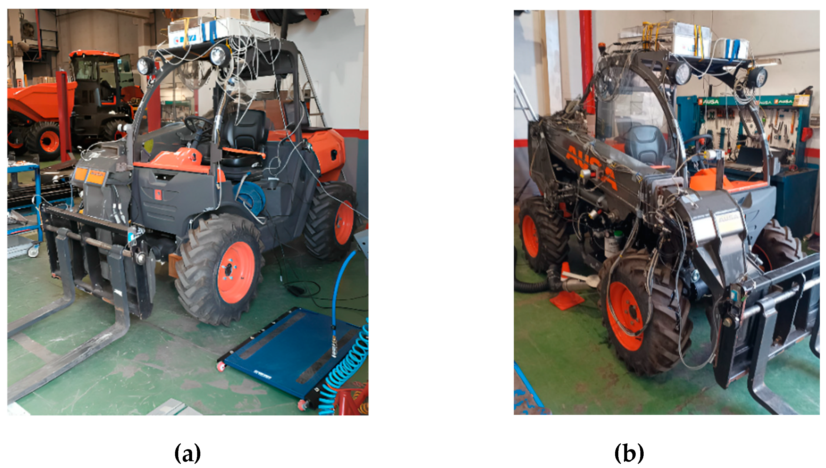
In this section, the tests conducted with the AUSA T164 telehandler are described. The objective of these tests is to evaluate the validity of the model described in previous chapters and to deepen the understanding of the machine's performance. The tests conducted have been grouped into two categories:
- 1.
- Tests to determine the ground reaction forces on the four wheels under different operating conditions of the machine. The results of these tests will be used to validate the virtual model from a mechanical perspective.
- 2.
- Tests on some specific functionalities of the machine, such as the self-leveling of the attachment fork. The experimental results will allow for the validation of the virtual model from a hydraulic perspective.
The test has been carried out under the EN 15000:2008 [4] standard and ISO 22915-14:2010 [5]. The Figure 18 presents a general view of the instrumented prototype. Table 5 details the data acquisition and processing equipment used the sensors are listed in Table 6.
Figure 17.
(a) Left frontal view; (b) Right frontal view of instrumented T164 prototype.
4.1.1. Tests to Determine the Ground Reaction Forces (Mechanical Domain)
The tests involve performing the movements of the telescopic boom, representing a normal service operation with the telehandler. Essentially, this consists of raising and lowering the boom, meaning elevating it and also extending the boom in various positions from the most retracted to the most extended (Positions A, B, C, D, E, and F), with different loads on the fork. The extension between the different positions is 250 mm. The tests were conducted at two speeds: slow speed, approx.1000 rpm (idle) and fast speed, 2850 rpm. The loads used were 0, 640, 1000, and 1600 kg. These loads correspond to the load capacity chart for the attachment being tested, in our case, a fork, in accordance with the requirements imposed by current safety standards. In this regard, we want to highlight that a significant portion of the tests have been conducted with a load of 640 kg, considering that with this load, all the movements permitted can be performed.
In Figure 18, the ground reaction force values at all four wheels during the boom's lifting motion (both upward and downward) are presented. In these tests, the telescopic arm was fully retracted, and the load on the fork was 0 and 1600 kg. An initial reading of these data suggests that the behavior during ascent and descent is very similar, and that the reactions on the rear wheels (Rear_Right and Rear_Left) are practically identical. The maximum and minimum values of the ground reaction forces as a function of the mass on the fork attachment are shown in Figure 19. This graph highlights and justifies the use of a sensor on the rear axle to provide the rear axle load measurement to the vehicle control system. This information is available to the operator to correct the stability of the vehicle by retracting the boom (in) and lifting the boom (up).
4.1.2. Tests to Determine the Functionality Performance (Hydraulic Domain)
From a hydraulic functionality perspective, we found it interesting to present the working conditions of the lift cylinder and the tilt cylinder under various operating conditions. For the hydraulic lift cylinder, Figure 20 shows the pressures on both sides of the hydraulic cylinder during the boom's upward and downward movements.
The pressure traces P1 are a function of the load and position of the lifting cylinder, but also of the resistive force of the slave cylinder. The latter causes the slope of the curve to vary, as indicated in [13]. In addition, Figure 21 illustrates the operating values of the overcentre valve connected to the piston-side chamber of the cylinder on a (Px, P1) diagram, as described in [28]. These values are approximately aligned along a line (depicted by a blue dashed line) parallel to the characteristic curve of the overcentre valve. This alignment suggests that during a slow descent of the lift cylinder, the overcentre valve needs to open, facilitating a flow rate of around 20 l/min for the four load conditions when the telescopic arm is retracted. Moreover, different loading conditions are highlighted through parallel dashed lines on the characteristic curve of the cylinder.
One of the most important features of a telehandler's performance is the fork attachment’s self-levelling capability. As illustrated in the hydraulic circuit diagram in Figure 14, to achieve self-levelling, a slave hydraulic cylinder has been utilized, which is driven by the boom, itself actuated by the lift cylinder. The chambers of the slave cylinder are connected to those of the tilt cylinder (piston-side chamber to piston-side chamber, and similarly for the rod-side chambers). With this setup, the slave cylinder functions as a positive displacement pump.
Figure 22 illustrates the levelling angle of the fork arms as the rod of the lift cylinder is retracted, causing the boom to move downward. For a load equivalent to a mass of 1600 kg, the levelling angle initially exhibits oscillatory behaviour due to the dynamic elasticity of the system, influenced by both mechanical components and hydraulic factors, such as fluid compressibility. This oscillatory behaviour significantly diminishes either when the load is reduced or as the boom moves upward. The limitations of the self-levelling system's error will be detailed in a subsequent section.
4.2 Experimental vs. Numerical Results: A Critical Examination of Their Validity and Model Limitations
- 1.
- Mechanical domain
Following the same order of presentation as the previous paragraph, a comparison between the results of the virtual model of the telehandler and the experimental results obtained during the tests is shown below. In order to cover the entire working range of the machine (both in lifting and extending), these comparisons have been conducted with a mass of 640 kg for the two positions of the extension arm: retracted (position A) and extended (position E). In Figure 23, the experimental values (solid line) and numerical values (dashed line) are shown. To highlight the accuracy of the virtual model, Figure 24 shows the percentage differences between the numerical (dashed line) and experimental values (solid line). In general, the percentage differences are less than ±10%, except for the downward movement of the arm in the extended position E, which exceeds this value. Similarly, the Figure 25 shows ground reaction forces (both experimental and numerical values) as a function of telescopic extension position with a 640 kg mass on the fork.
The discrepancies between the numerical and experimental results can basically be attributed to the following three aspects: Firstly, the experimental measurements, although the load cells used are highly precise, transferring data from the load cells to our acquisition system introduce a undesirable temporal error. This is evident in the graphs, which, instead of following a continuous line, appear as broken lines with step-like segments. Secondly, at the beginning and end of the movements, there is a certain disturbance caused by the same operator, which affects the readings of the load cells. Finally, the virtual model includes a platform comprising many elements, but it has been represented by a single rigid body with a centre of mass. It should also be noted that in the tests, a non-uniform load consisting of steel plates was utilized, whereas in the virtual model, a uniform load with a cube-shaped side of 1 meter was considered. Any small variation in the coordinates of the centre of mass can introduce significant variations in the ground reaction forces. This source of error will be partially corrected in a second version of the virtual model, which will involve discretizing the platform into multiple solid bodies. In Figure 23 it is shown the evolution of the ground reaction forces: experimental values (solid line) and numerical values (dashed line) during the telehandler tests while lifting and lowering a 640 kg mass.
- 2.
- Hydraulic domain
In this paragraph, we find it interesting to present the comparative results between the numerical values and the experimental outcomes of the self-leveling system, which partially reflects the concept of machine stability. Figure 26 depicts the numerical results (dashed line) showing the evolution of the self-leveling error during the upward and downward lifting boom movements. The table (on the right side) summarizes the experimental values corresponding to one cycle, as well as the accumulated error over five consecutive cycles. These results underscore the effectiveness of the T164 telehandler’s hydraulic self-leveling system, as well as the precision of the numerical model outcomes.
- 3.
- Other comments
We do not wish to conclude this section on the critical analysis of the obtained results without dedicating a few lines to specific analysis that have been conducted to identify the elasto-damping parameters of the tires.
During the development of the virtual model, one of the challenges we encountered was in estimating the parameters of tire stiffness and damping constant. As a starting point, we adopted the values of J. A. Lines 1991 [31] [32], which were compared with data provided by the tire supplier. These values are summarized in Figure 27. According to Figure 28 (left), it has been deemed appropriate to use a tire stiffness of 600 kN/m for the virtual model. On the other hand, according to Figure 28 (right), we considered it necessary to increase the values suggested by Lines [32] by a factor of 10, primarily to avoid oscillatory behavior and to align them more closely with the experimental results.
5. Conclusions and Final Remarks
This study has introduced a simple and basic virtual model developed using multi-physics modelling with Bond Graph methodology, emphasizing its relevance for addressing stability challenges in telehandlers. The model serves as a valuable tool in the predesign and design stages of telehandlers, providing essential insights into their performance characteristics, including load chart definition, particularly in the context of electrified versions.
The model incorporates critical components essential for replicating both mechanical and hydraulic aspects of the vehicle, such as the chassis, rear axle, telescopic boom, attachment fork, and wheels. The complexity of these components necessitates a comprehensive three-dimensional treatment to accurately capture spatial dynamics.
An illustrative example, supported by experimental data, has been provided to showcase the model's fundamental functionality. Special attention has been given to calculating wheel reaction forces on the ground and analyzing the hydraulic self-leveling phenomenon of the attachment fork. It is noted that discrepancies of 10 % are typically well within the tolerable range for a well-designed mechanical domain. More precise models may not be necessary for the present task, particularly considering the significant variability in field operating conditions and system changes over time, including component variability, and uncertainty in some parameters. In the hydraulic domain, the virtual model demonstrates excellent accuracy and sensitivity. Numerical results obtained validate the BG-3D simulation model of the telehandler with 20-Sim as a promising tool for estimating stability limits with satisfactory precision, capable of predicting dynamic behaviors under various operating conditions.
In summary, this study underscores the effectiveness of the developed virtual model in comprehending and predicting telehandler dynamics. Its capacity to accurately simulate diverse mechanical and hydraulic aspects, complemented by experimental validation, positions it as a valuable asset for industry engineers and designers. Furthermore, the use of multi-dimensional Bond Graph not only contributed to a more productive working environment but also led to a more fundamental understanding of the key physical attributes. It lays a foundation for future research in advancing longitudinal and lateral stability of electrifying non-road mobile machinery (NRMM).
Author Contributions
The experimental works was done by B.P., G.R., M.T., O.C. and E.C. The data acquisition and data processing were completed by B.P., J.F. and E.C. The formation and expertise of 20Sim & BG and the BG model adjustments used were completed by B.P., GF and EC. The manuscript was finalized by B.P., G.F., G.R., JF and E.C. The investigation was leaded and supervised by E.C.
Funding
“This research received no external funding”.
Acknowledgments
We thank AUSA company, who provided the telehandler prototype and expertise, used in this research. Also Jaume Bonastre Romera of CATMech, UPC for his valuable help.
Conflicts of Interest
The authors declare no conflict of interest.
Appendix A. Mathematical formulations for multi body systems (MBS)
i) Newton-Euler equations:
It arises from applying the conservation of momentum and angular momentum to a free solid, establishing a relationship between its motion and the forces and moments acting upon it. Expressing Newton's second law.
Furthermore, the orientation of the solid is defined by the laws of Euler, which can be considered as an extension of Newton's laws to rigid bodies. The Euler's equation describes the rotation of a body with respect to a reference frame fixed to the solid itself.
These two vector equations define the motion of a solid in space.
There are six equations for each solid, which implies large-sized models compared to the degrees of freedom of the system. Solving this system of equations is what makes the method challenging, primarily due to the nonlinearity that arises and secondly due to the constraint forces that arise from the connections, which are unknown and included in the external force vector. Despite these challenges, it is a formulation whose application is independent of the system's topology, resulting in easy systematization and its use in general methodologies.
ii) Lagrange equations:
Lagrange developed his formulation with the aim of reducing the number of equations to the degrees of freedom of the system. Starting from the principle of virtual work and applying D'Alembert's principle to a rigid body. By formulating the system with independent coordinates in a multi-body setup, the number of equations equals the number of degrees of freedom"
iii) Hamilton equations:
The reformulation of the Lagrange equation leads to the Hamiltonian equation. In the Hamiltonian formulation, the velocity (q dot) is replaced by the momentum that defines the solid, resulting in the Hamiltonian as H (q, p, t), where p represents the momentum. This momentum is used to generate first-order equations in terms of generalized coordinates and canonical momentum.
These equations form a second-order differential system, which is solved using numerical methods, primarily due to nonlinearity. In this regard, the Hamiltonian equations provide an alternative to reduce the order of the system, transforming it from a system of 2n second-order differential equations to a system of n first-order differential equations.
iv) Gibbs-Appell equations:
It is an alternative general formulation of classical mechanics. Actually, Lagrange's equations of motion are a special case of the Gibbs-Appell equations of motion.
v) Kane equations:
Kane’s method provides a convenient way of deriving the dynamic equations of motion for complex multibody systems having many degrees of freedom. It is becoming increasing popular among the biomechanists. The key characteristic shared by Lagrange's and Kane's equations is the conversion to generalized coordinates, which allows for the elimination of system constraint forces. In the typical derivations of Lagrange's equations, this is attributed to the restricted nature of virtual displacements, where displacements are considered virtual if the virtual work of constraint forces becomes zero. Conversely, in Kane's equations, constraint forces are eliminated by appropriately selecting the vector with which Newton's law is multiplied (dot product).
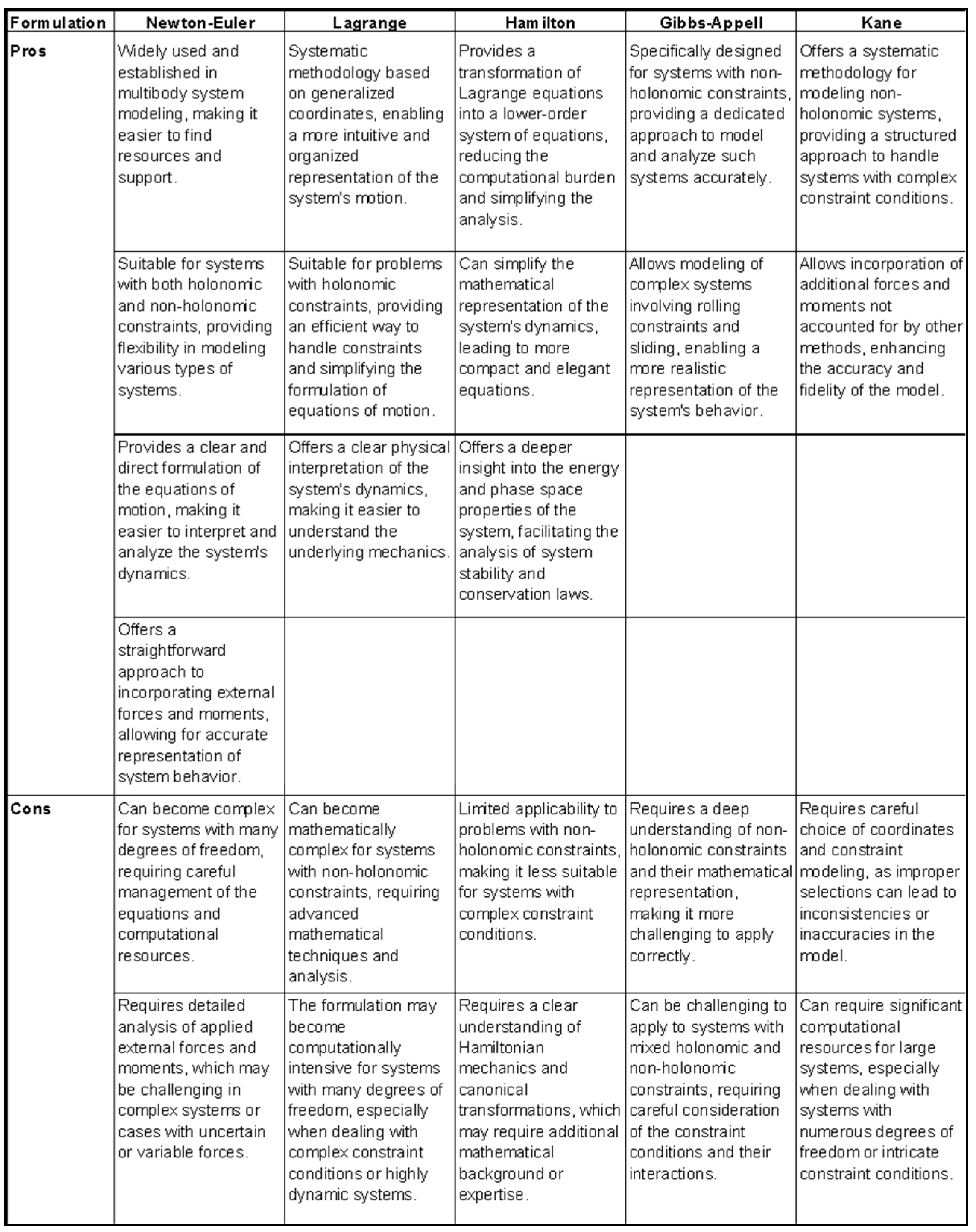
A comparison of the mentioned methods, highlighting their pros and cons, is showed below.
Table A1.
Comparison of the main diferent mathematical formulations for MBS.
 |
Appendix B. Description of the Multi-Bond Graphs submodels used in the telehandler model of 20-Sim
The Multi-Bond Graphs Submodels used to solve the spatial dynamics of the multibody telehandler are described bellow.
- 1.
- Rigid Body
To determine the spatial motion of the rigid body, the well known Euler equations are used, which appear in (1) and (2). The first one represents the conservation of linear momentum, written as:
where F, w, p represents the external forces, the angular velocity vector and the linear momentum vector respectively; d/dt, d/dt|rel, represent the derivative respect to the inertial frame, and the derivative respect to the body attached frame.
The second of the Euler equations sets up the conservation of angular momentum:
where M, h represent the external torque and the angular momentum vector.
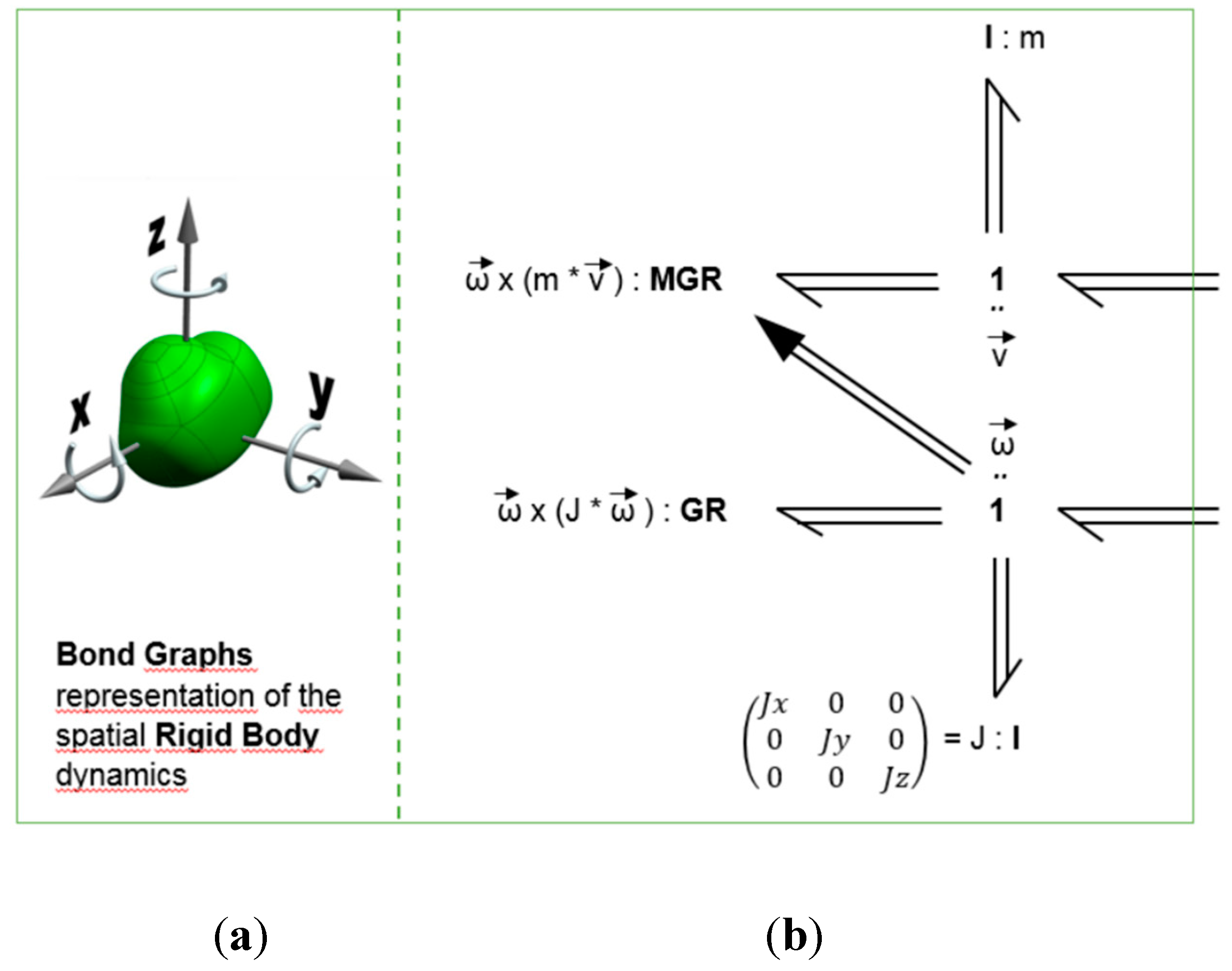
The Bond Graph representation of the 3-dimensional motion of a rigid body based on the Euler equations is shown in Figure A1. Three power multibonds are attached to the upper 1-junction representing the centre of mass speed vector v. The effort variable associated to the multi-bond pointing into the inertia I:m is the first term in the right-hand side of (1); the effort of the multi-bond on the left is the second term of the right-hand side, while that of the multi-bond on the right is the term of the left-hand side. The latter represents the external forces acting on the centre of mass point of the body and, thus, it is an input or external connection port of this module. An analog description can be given for the lower 1-junctionconcerning the rotational speed vector w and the torques in (3). Note the multisignal link from the lower 1-junction to the MGR element, necessary to implement the modulation of the second term in the right-hand side of (1) by the speed w. The components of the inertia matrix J are the principal moments of inertia with respect to the principal axes of the rigid body. The lower part of Figure A1 is the mask which will be used as a compact representation when connecting this model to others in the case of modelling a complex system.
Figure A1.
(a) Icon to represent 3D Rigid Body; (b) Bond Graph of 3D Rigid Body Dynamics (RB).
- 2.
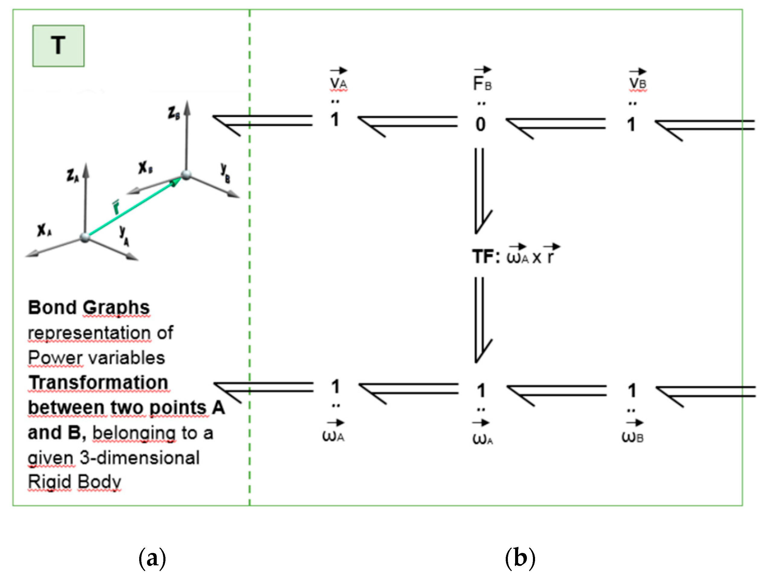
- Transformation of Translation
The port variables of the above model are defined respect to the system attached to the centre of mass of the rigid body. Referring these port variables to the coordinates of interconnection with other bodies allow to couple the whole model. Figure A2 shows the Bond Graph implementation of the equation system representing how the port variables of two arbitrary points 'A' and 'B' of a given spatial body transform each other. The equations relating the linear and rotational efforts are the following:
For the flow variables the equations are the following:
Figure A2.
(a) Icon to represent Transformation; (b) Bond Graph Transformation between point A and B (T).
Figure A2.
(a) Icon to represent Transformation; (b) Bond Graph Transformation between point A and B (T).
- 3.
- Transformation of Rotation
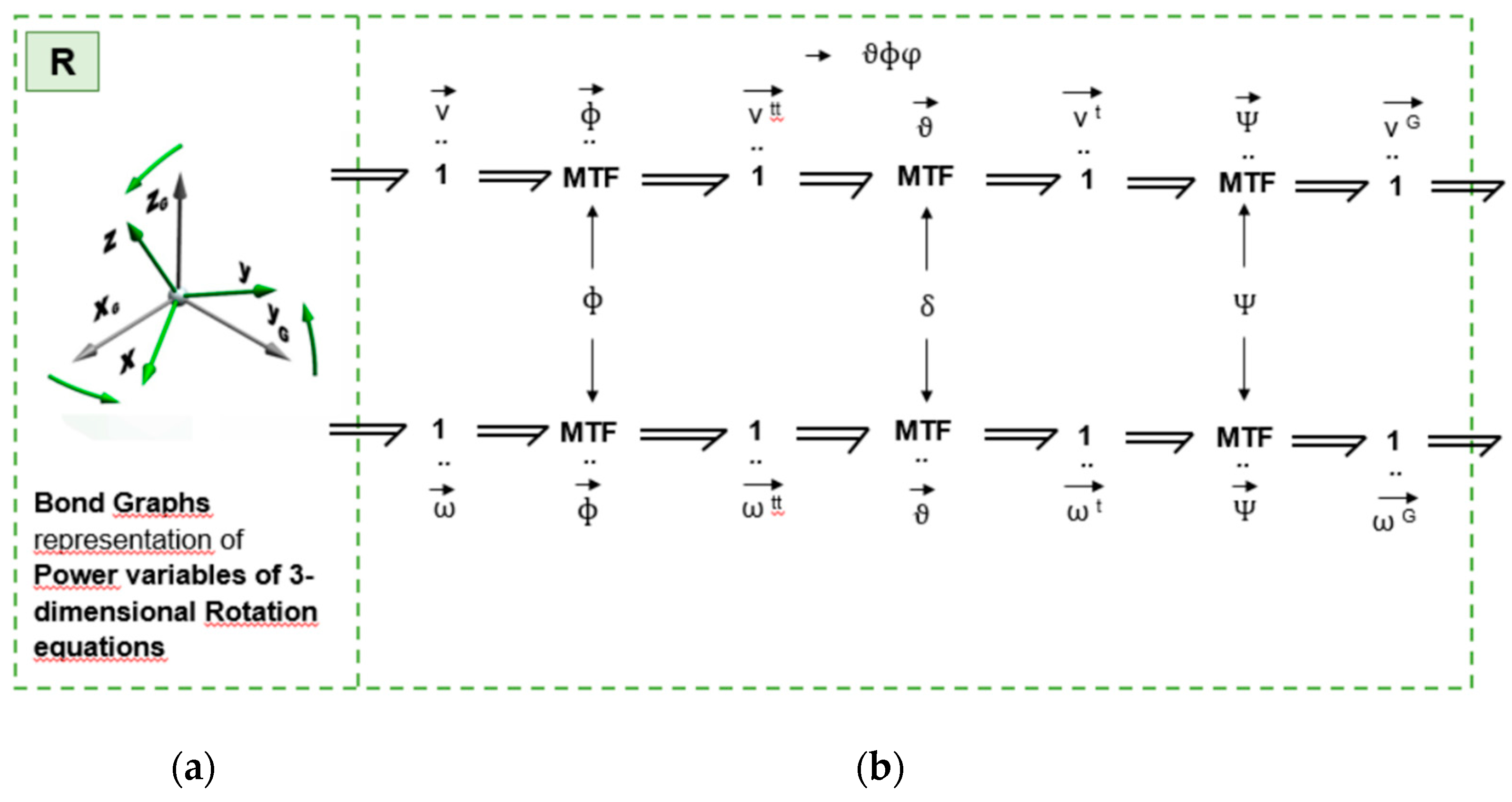
To transform the dynamic equations from those expressed in the body attached frame of reference (roll, pitch and yaw axes) to a spatially fixed frame of reference (X,Y,Z : inertial frame) it is necessary to choose some parameterization for the rotations. Among the multiple possibilities, Euler angles are used. To transform these rotations the following equations are used:
where, 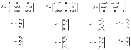
In Figure A3, where the power variables are transformed from (x,y,z) axes to the rotated ones (X,Y,Z) according to the angles respect to each axis. It may be observed that while the flow variables are rotated from (xyz) to (X Y Z), the effort variables are transformed back from (XYZ) to (xyz).
Figure A3.
(a) Icon to represent 3D Rotation; (b) Bond Graph 3D Rotation (R).
- 4.
- Revolute Joint.
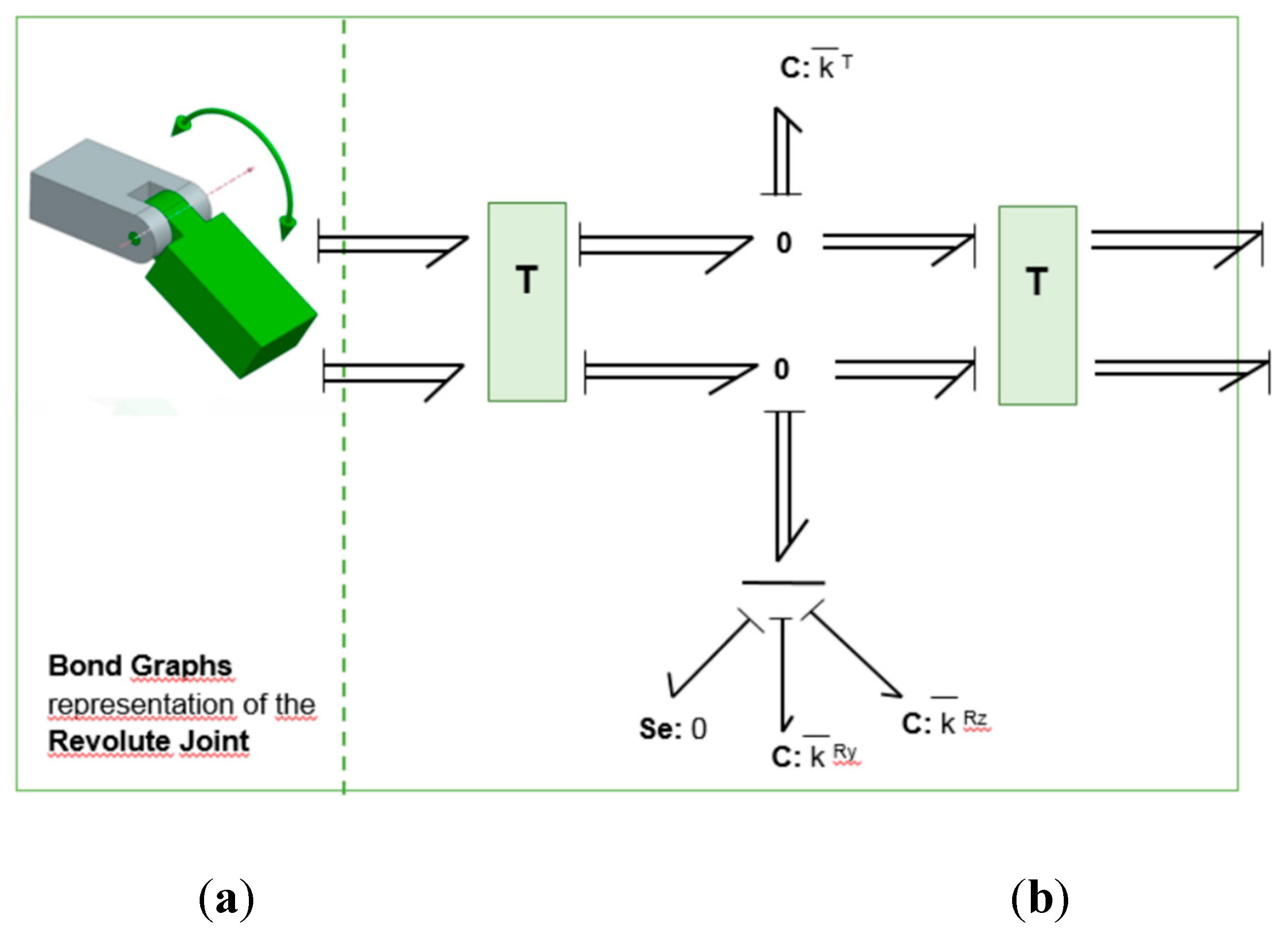
The Revolute Joint (RJ) element is a joint that allows turning the bodies joined between them. Therefore, three translations and two rotational degrees of freedom are constrained, leaving only one rotation degree of freedom free. The Bond Graph representation of the Revolute Joint is shown in Figure A4. RJ constrains are controllable by the use of C elements. The parameter must be accurate enough to obtain approximately . Figure A4 shows two C elements with parameters that allow to obtain and , the same constraint for the rotational fixations. Therefore, this kind of joint has only one degree of freedom. The Se=0 null effort source does not impose any x-axis torque at both joint ends. Due to this joint condition, only one angle changes between those connected bodies, the modular transformation associated may be solved with only one of the matrices in 3 i.e. if rotation axis is x (as in this case), then only matrix has to be used.
Figure A4.
(a) Icon to represent Revolute Joint; (b) Bond Graph of Revolute Joint (RJ).
- 5.
- Prismatic Joint.
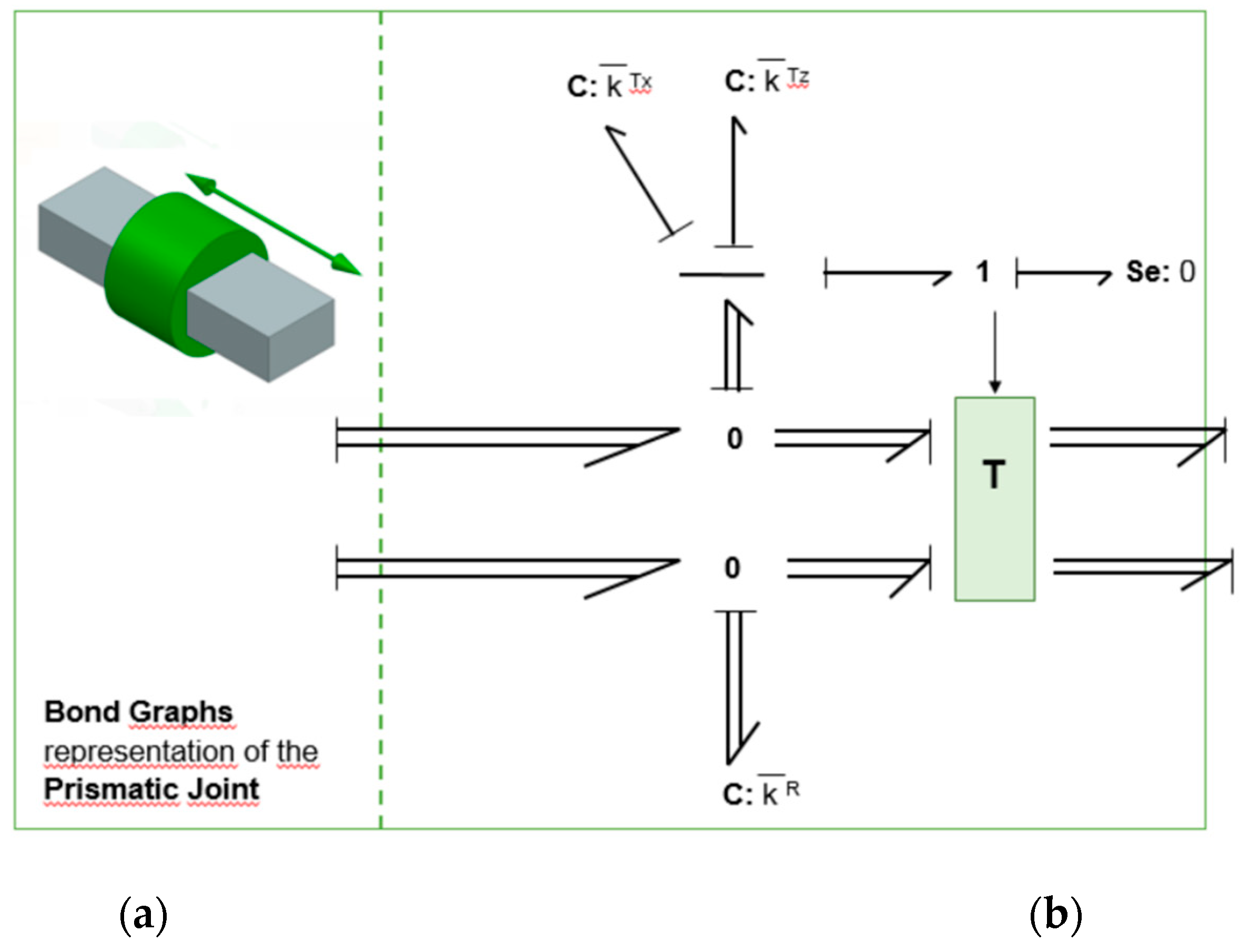
The Prismatic Joint (PJ) is a joint that allows only a straight displacement between its joined bodies, fixing the remaining two translational and the whole three rotational degrees of freedom. Therefore, only one generalized coordinate is free to change. Figure A5 shows the Bond Graph implementation of the Prismatic Joint. Here, as the previously RJ joint, constrains are implemented with the usage of C elements with some parameters to be tuned in order to get , and . Then, for this kind of joint, only a displacement on the local y-axis direction between 1 and 2 extremes is allowed. The effort source Se=0 is introduced for this purpose, with a null force on the y-axis and both joint ends. The transformation shown is similar to that presented above in 2, with the only difference that now, it is modulated, with the modulation factor (in this case ry) that depends on the relative position between the joint extremes.
Figure A5.
(a) Icon to represent Prismatic Joint; (b) Bond Graph of Prismatic Joint (PR).
References
- Priora, G. Monitor and control system of the dynamic stability on a telescopic handler with telemetry and experimental data, Thesis 2019. Politecnico di Torino (Italy).
- Machinery Regulation (UE) 2023/1230. https://eur-lex.europa.eu/eli/reg/2023/1230/oj.
- CEN/TS 1459-8:2018 (MAIN). Rough-terrain trucks - Safety requirements and verification - Part 8: Variable-reach tractors.
- CEN/EN 15000:2008. Safety of industrial trucks. Self propelled variable reach trucks. Specification, performance and test requirements for longitudinal load moment indicators and longitudinal load moment limiters.
- ISO 22915-14:2010 ISO 10896-1:2020.. Industrial trucks — Verification of stability. Part 14: Rough-terrain variable-reach trucks.
- Rough-terrain trucks — Safety requirements and verification. Part 1: Variable-reach trucks.
- Safe use of telehandlers in construction. Good Practice Guide. 2ed 2015. ref nº CPA 1101. Construction Plant-hire Association. Health Safety Executive (HSE), UK.
- Hunter A.G.M. A review of research into machine stability on slopes, Safety Science, Volume 16, Issues 3–4, 1993, Pages 325-339, ISSN 0925-7535. [CrossRef]
- Bietresato, M.; Mazzetto, F. Stability Tests of Agricultural and Operating Machines by Means of an Installation composed by a Rotating Platform (“Turntable”) with Four Weighting Quadrants. Appl. Sci. 2020, 10, 3786. [Google Scholar] [CrossRef]
- Urkullu, G. , Integración de las ecuaciones de la dinámica de sistemas multicuerpo mediante diferencias centrales de orden dos. Tesis (2019). Universidad del País Vasco - Euskal Herriko Unibertsitatea, Leioa, España.
- Garcia-Vallejo, D. , Mayo J., Escalona JL, Domínguez J., Three-dimensional formulation of rigid-flexible multibody systems with flexible beam elements. Multibody System Dynamics 20 (2008), 1-28.
- Haoliang Guo, Xihui Mu, Fengpo Du, Kai Lv Lateral Stability Analysis of Telehandlers Based on Multibody Dynamics WSEAS Transactions on Applied and Theoretical Mechanics. E-ISSN 2224-3429 Vol1 11, 2016.
- Altare, G., Lovuolo, F., Nervegna, N., & Rundo, M. (2012). Coupled Simulation of a Telehandler Forks Handling Hydraulics. International Journal of Fluid Power, 13, 15–28. [CrossRef]
- Patil A., Radle M. Hydraulic and multibody combined simulations for electric forklift design using modelica. International Journal of Engineering Science and Technology 10(9):27-35, March 2022 10(9):27-35. [CrossRef]
- Borutzky, W., Bond Graph Methodology: Development and Analysis of Multidisciplinary Dynamic System Models. ISBN 13: 9781848828810.
- Romero, G. Procedimientos optimizados utilizando métodos simbólicos para la simulación de sistemas dinámicos mediante Bond-Graph. Tesis doctoral 2005. Universidad Politécnica de Madrid, España.
- Bos, A.M. Modelling multibody systems in terms of multiBond Graphs with application to a motor cycle (1986). 90-9001442-X, Enschcde, The Netherlands.
- Tiernego, M.J.L. , Bos A.M. Modelling the dynamics and kinematics of mechanical systems with multiBond Graphs. Special issue on physical structure in modelling (1985), pp. 37-50. J. of Franklin Institute, Philadelphia, EEUU.
- Karnopp D., Rosenberg R. and Perelson A. S., "System Dynamics: A Unified Approach," in IEEE Transactions on Systems, Man, and Cybernetics, vol. SMC-6, no. 10, pp. 724-724, Oct. 1976. [CrossRef]
- Marquis-Favre, Wilfrid and Serge Scavarda. “Alternative Causality Assignment Procedures in Bond Graph for Mechanical Systems.” Journal of Dynamic Systems Measurement and Control-transactions of The Asme 124 (2002): 457-463.
- Zeid A., Chung C-H. Bond Graph modelling of multibody systems: a library of three-dimensional joints. Journal of the Franklin Institute, Volume 329, Issue 4, 1992, p 605-636, ISSN 0016-0032. [CrossRef]
- Cellier, F.E., Nebot, A.: The Modelica Bond Graph Library, p. 10 (2005).
- Zimmer, Dirk, and François E. Cellier. The Modelica multi-Bond Graph library. Proceedings of the 5th International Modelica Conference (2006). Vienna, Austria.
- Filippini G., Nigro N., and Junco S. Vehicle dynamics simulation using Bond Graphs. International Modelling and Simulation Multiconference (2007). Argentina.
- Boudon, B. , Dang T.T. Margetts R, Borutzky W. Malburet F. Simulation methods of rigid holonomic multibody systems with Bond Graphs. Advances in Mechanical Engineering (2019) Vol. 11(3) 1–29. [CrossRef]
- De las Heras S., Codina E. Modelización de sistemas fluidos mediante bondgraph. 1997. ISBN: 84-605-7035-5.
- Pacejka H.B. Tire and Vehicle Dynamics. Butterworth-Heinemann. ISBN 978-0-08-097016-5. (2012). [CrossRef]
- Berne L.J., Raush G., Roquet P., Gamez-Montero P. J. and Codina E. Graphic Method to Evaluate Power Requirements of a Hydraulic System Using Load-Holding Valves. Energies (2022). 15, 4558. [CrossRef]
- Merrit H.E., Hydraulic Control Systems. John Wiley & sons, (1967) ISBN 0-471-59617-5.
- Borghi, M. , Milani M., Poaluzzi R., Influence of Notch Shape and Number of Notches on the Metering Characteristics of Hydraulic Spool Valves. International Journal of Fluid Power 6(2):5-18 (2005). [CrossRef]
- Lines J.A., Murphy K. The radial damping of agricultural tractor tyres. Journal of Terramechanics Volume 28, Issues 2–3 (1991), Pages 229-241. [CrossRef]
- Lines J.A., Murphy K., The stiffness of agricultural tractor tyres. Journal of Terramechanics Volume 28, Issue 1 (1991), Pages 49-64. [CrossRef]
Figure 2.
Figure 2. Main causes of overturn accident. Source: Health Safety Executive, HSE (UK) [7].
Figure 2.
Figure 2. Main causes of overturn accident. Source: Health Safety Executive, HSE (UK) [7].
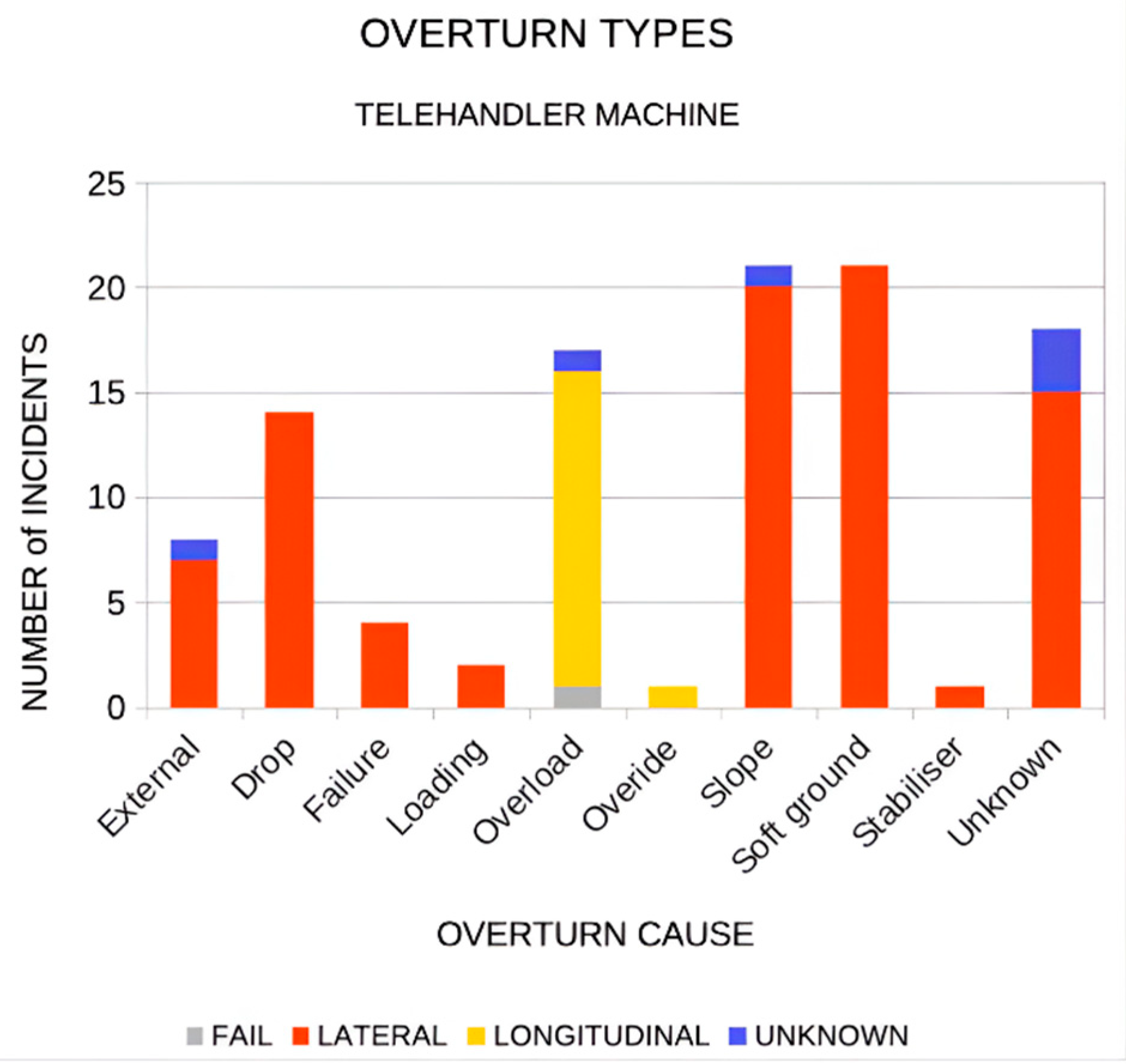
Figure 3.
Modelling dynamic behavior of the telehandler, generic point of view.
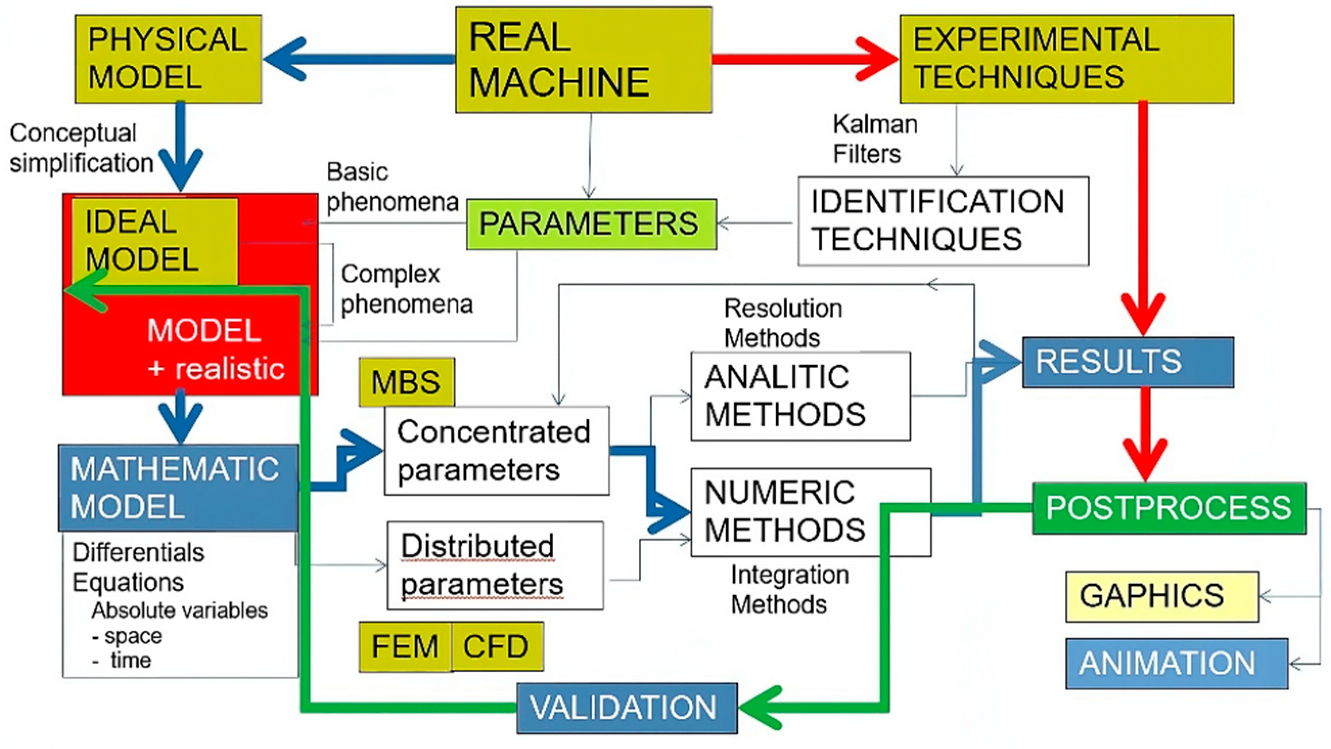
Figure 4.
Modeling the dynamic behavior of a machine with Bond Graph.
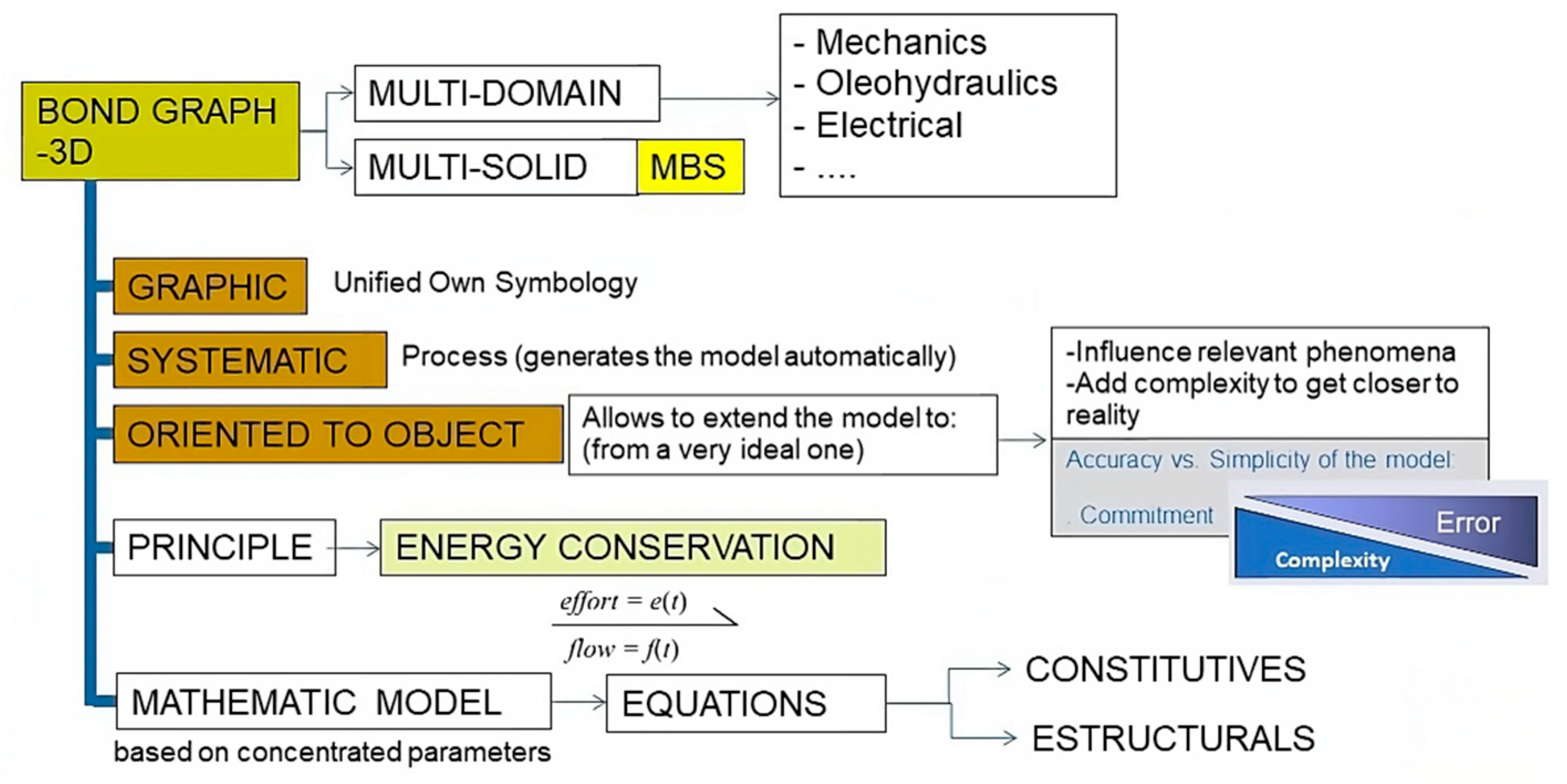
Figure 5.
Telehandler model (3D-Bond Graph scheme).
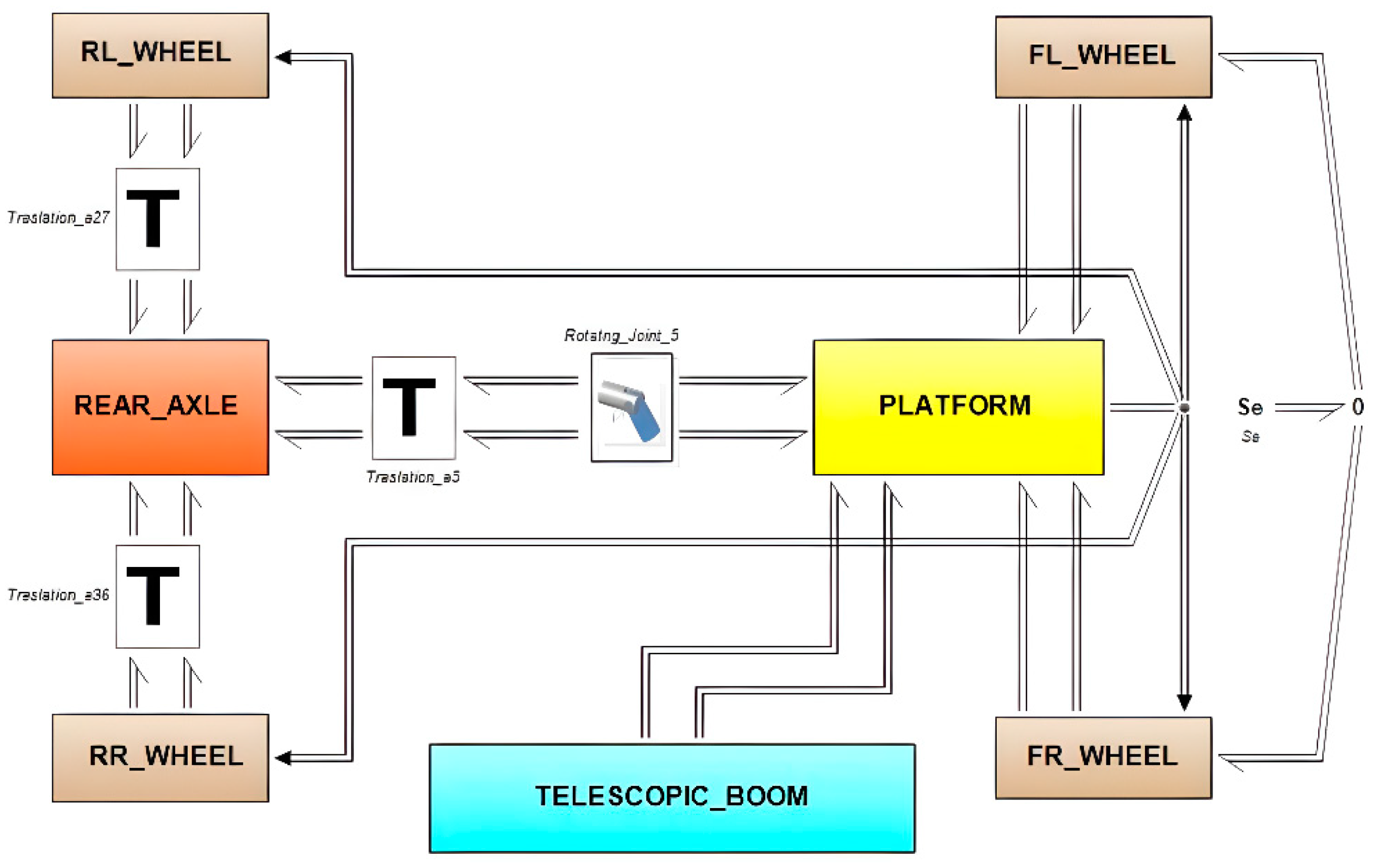
Figure 6.
Bond Graph representation of platform submodel (3D-Bond Graph Scheme).
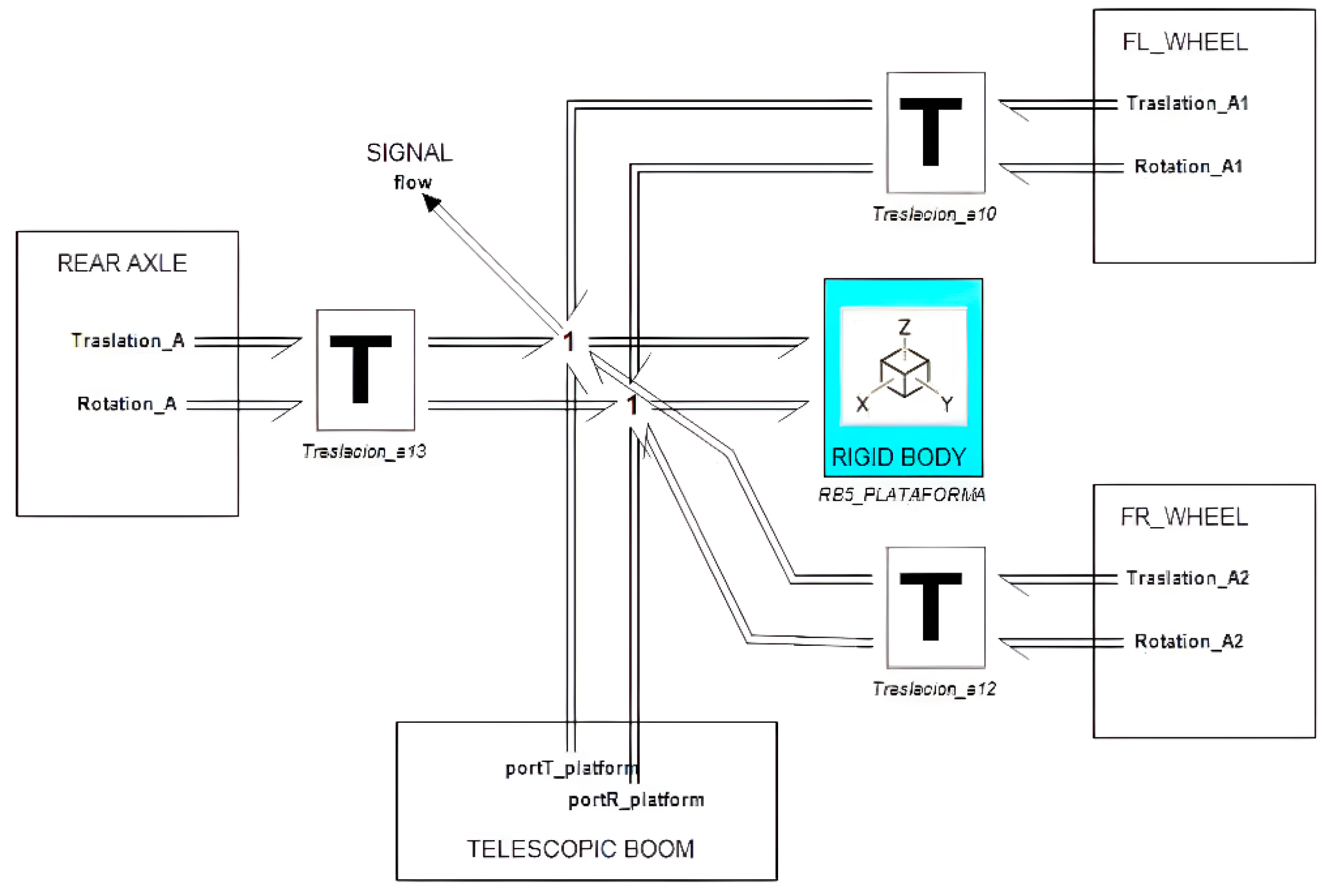
Figure 7.
Bond Graph representation of Rear Axle mechanism model (3D-Bond Graph Scheme).
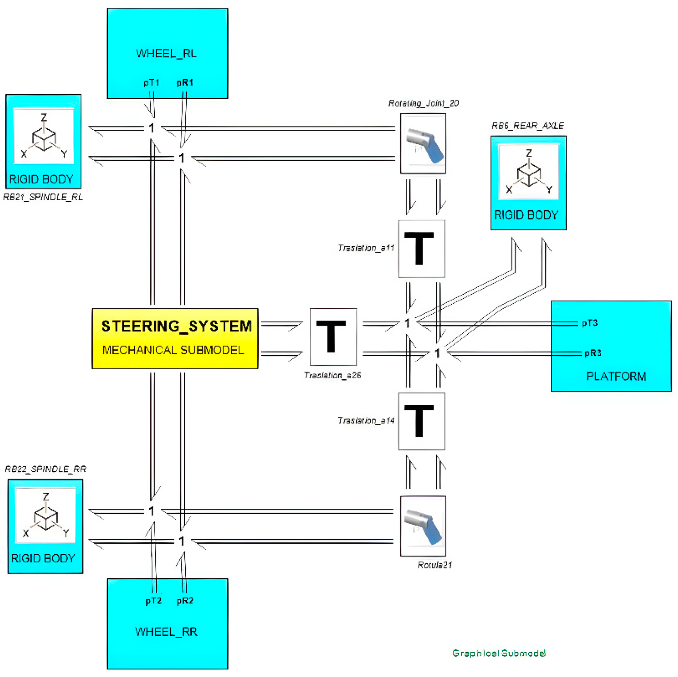
Figure 8.
Bond Graph representation of Steering System Model (3D-Bond Graph Scheme).

Figure 9.
Bond Graph representation of Tire-Soil Interaction model (3D-Bond Graph Scheme).
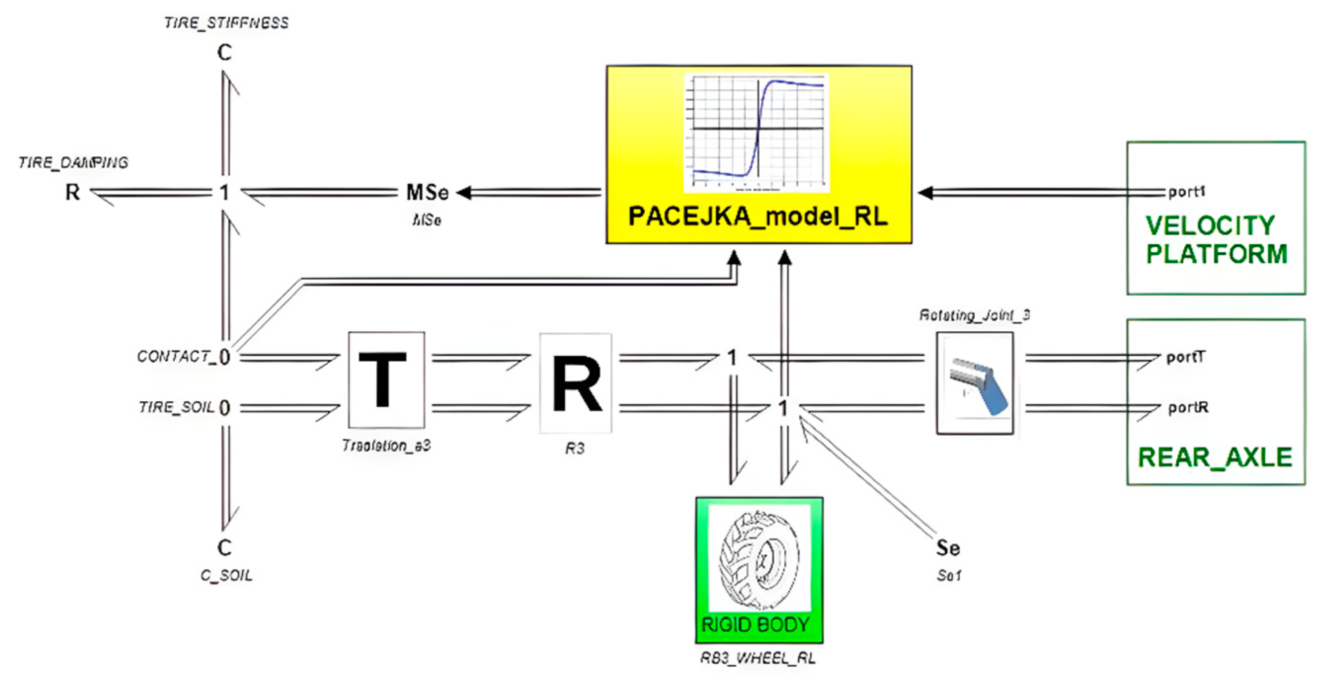
Figure 10.
Bond Graph representation of Telescopic Arm System Model (3D-Bond Graph Scheme).
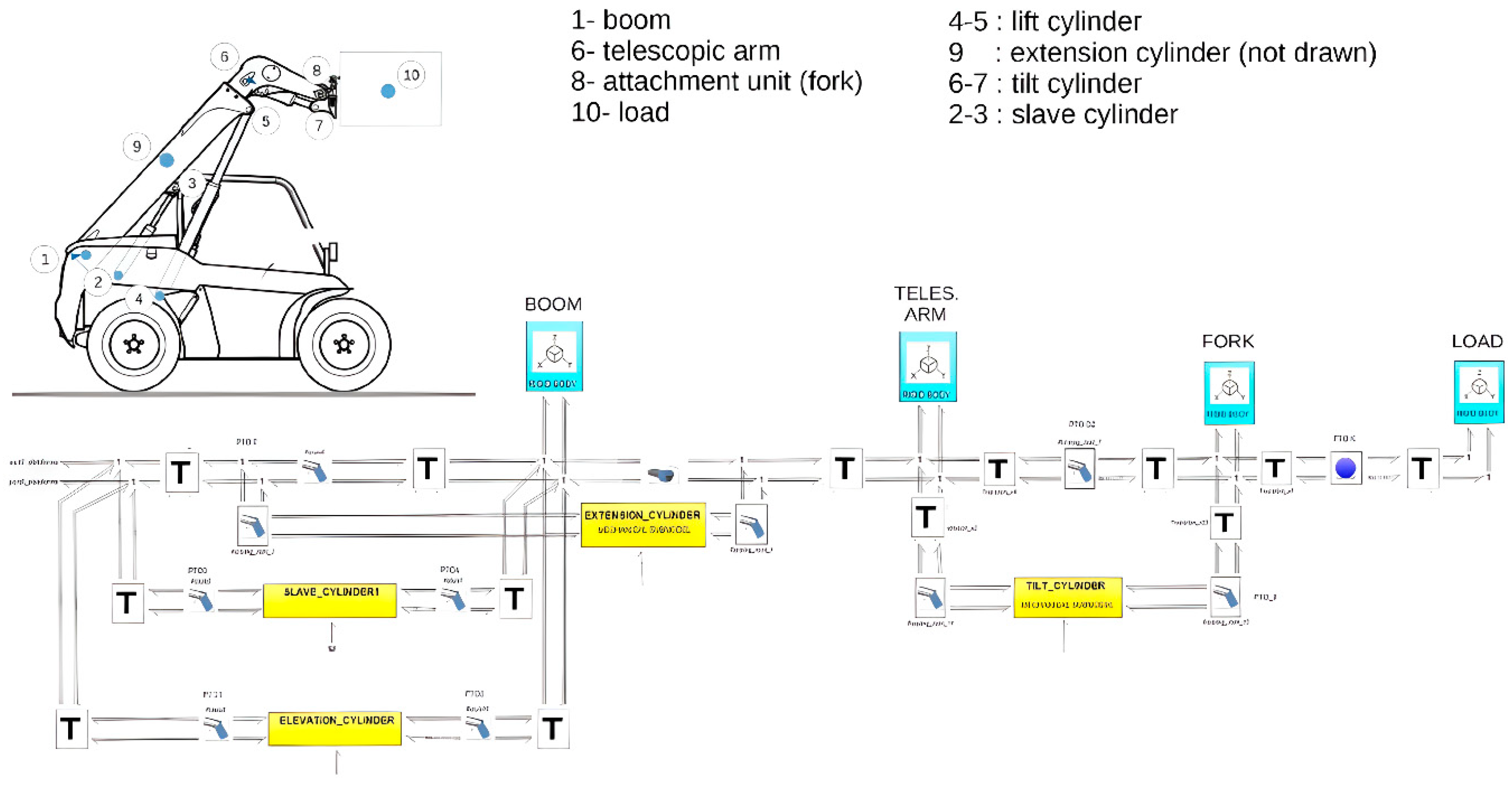
Figure 11.
Bond Graph representation of hydraulic cylinder subModel (3D-Bond Graph Scheme).
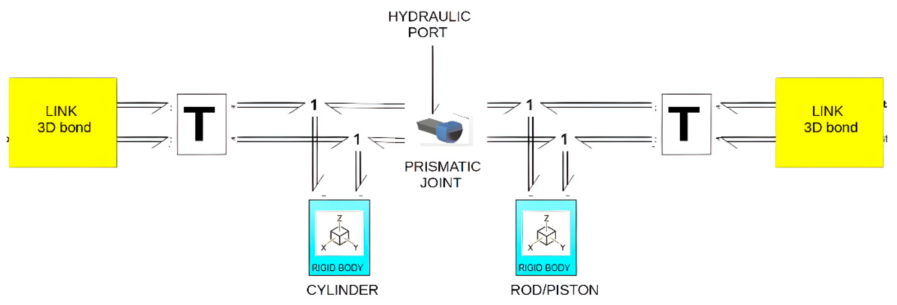
Figure 12.
Hydraulic circuit corresponding to the actuation of the telescopic arm and its attachment.
Figure 12.
Hydraulic circuit corresponding to the actuation of the telescopic arm and its attachment.
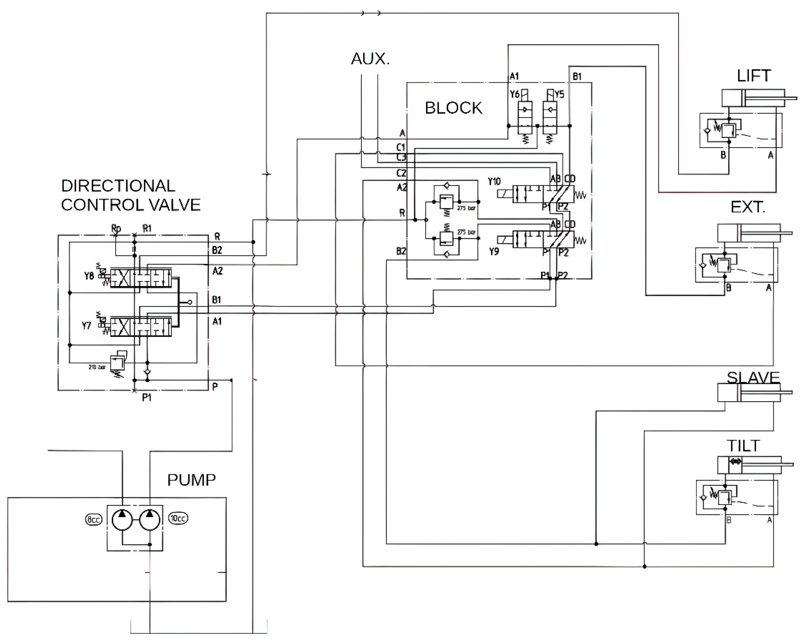
Figure 13.
Hydraulic actuator system of boom arm (1D BG submodel scheme).
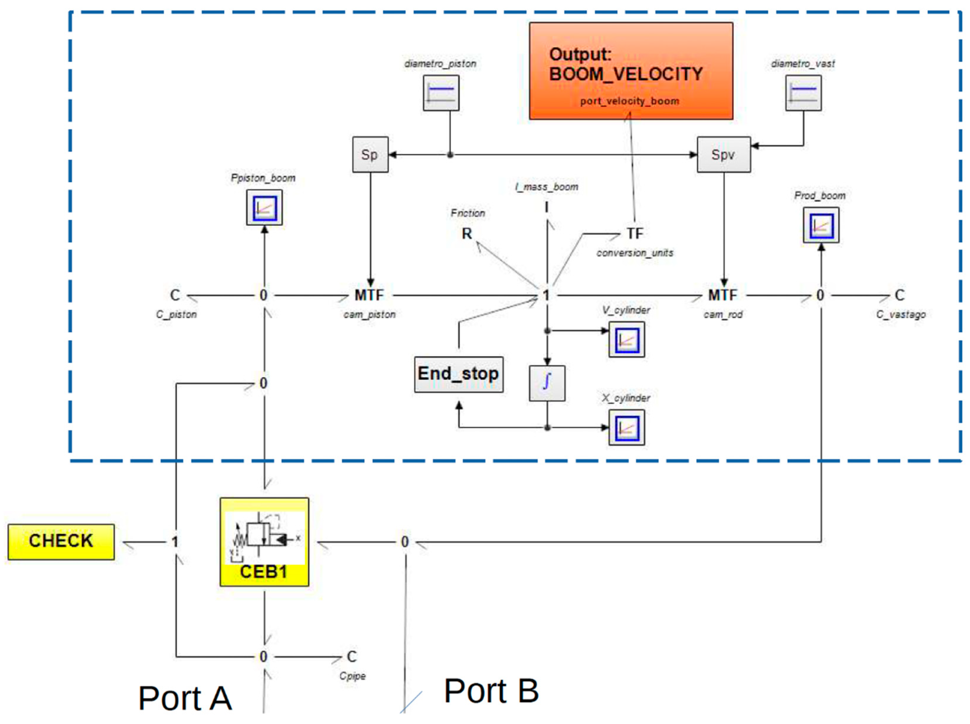
Figure 14.
Load holding valve, as well called Overcentre valve (1D-BG submodel scheme).
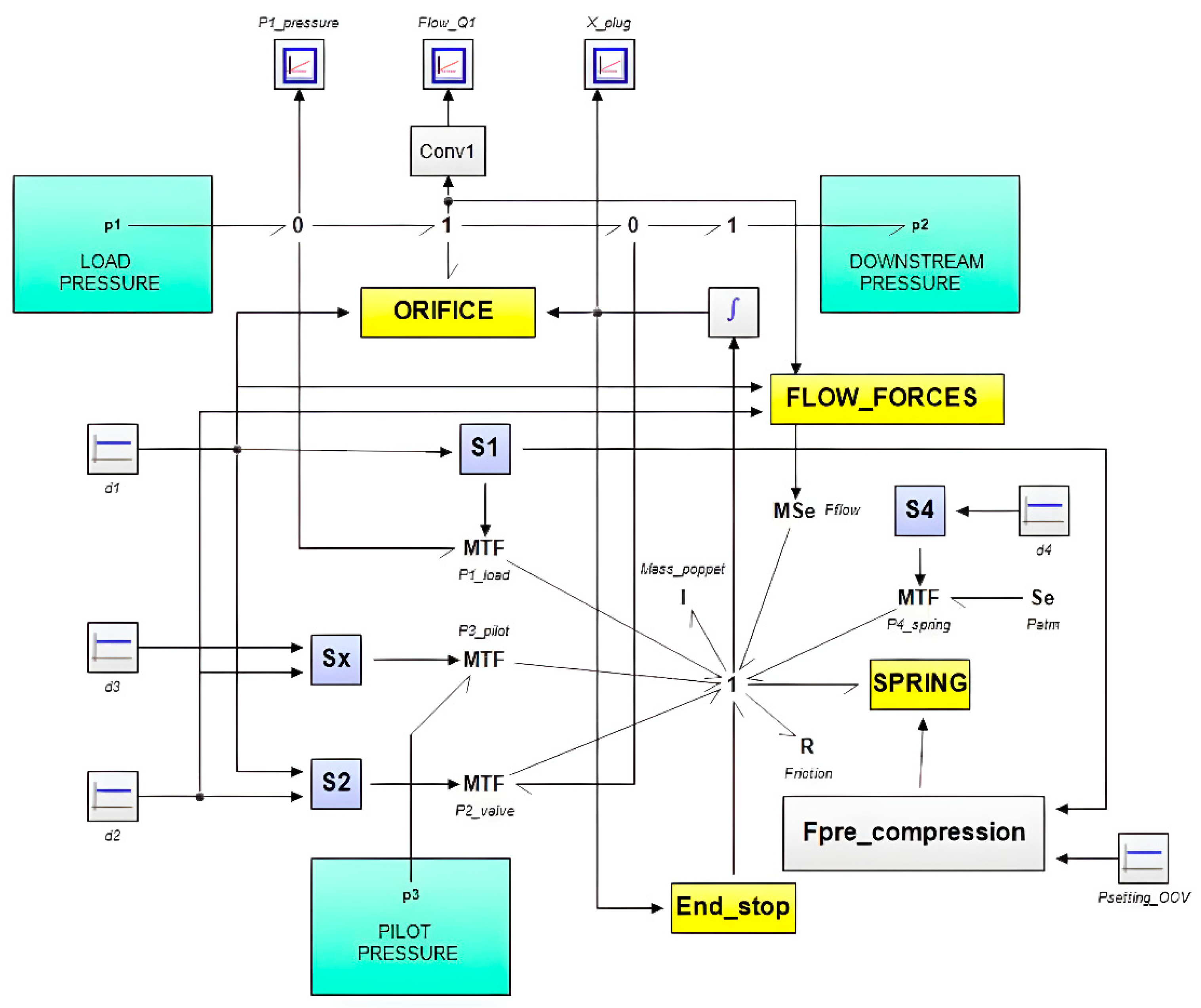
Figure 15.
Hydraulic block of Directional Control Valves (1D-BG submodel scheme).

Figure 16.
Directional Control Valve, DCV (1D-BG submodel scheme).
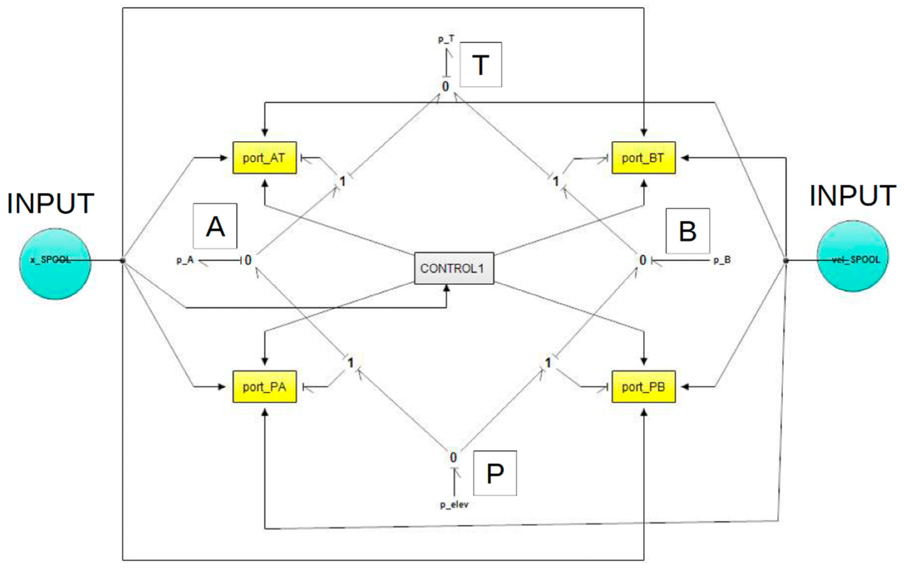
Figure 18.
Ground reaction forces during lift movement (upward and downward) with loads on the fork 0 and 1600 kg when the telescopic arm is fully retracted.
Figure 18.
Ground reaction forces during lift movement (upward and downward) with loads on the fork 0 and 1600 kg when the telescopic arm is fully retracted.
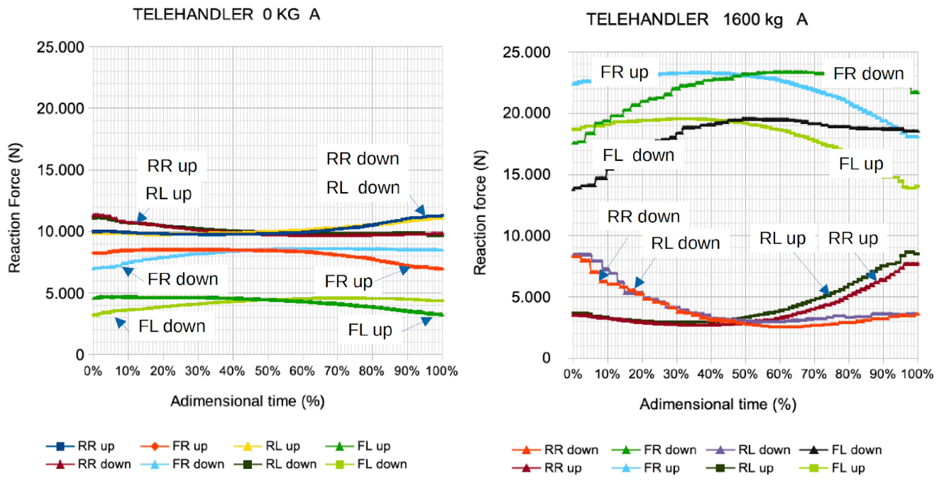
Figure 19.
Ground reaction forces as a function of mass on the fork attachment (The solid line corresponds to maximum values, and the dashed line corresponds to minimum values).
Figure 19.
Ground reaction forces as a function of mass on the fork attachment (The solid line corresponds to maximum values, and the dashed line corresponds to minimum values).
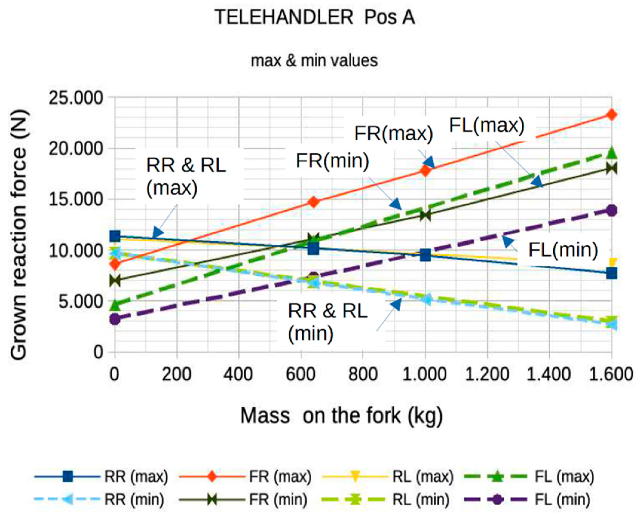
Figure 20.
Evolution of pressures in the chambers of the lift cylinder during the upward and downward movement of the lift arm for four load conditions.
Figure 20.
Evolution of pressures in the chambers of the lift cylinder during the upward and downward movement of the lift arm for four load conditions.
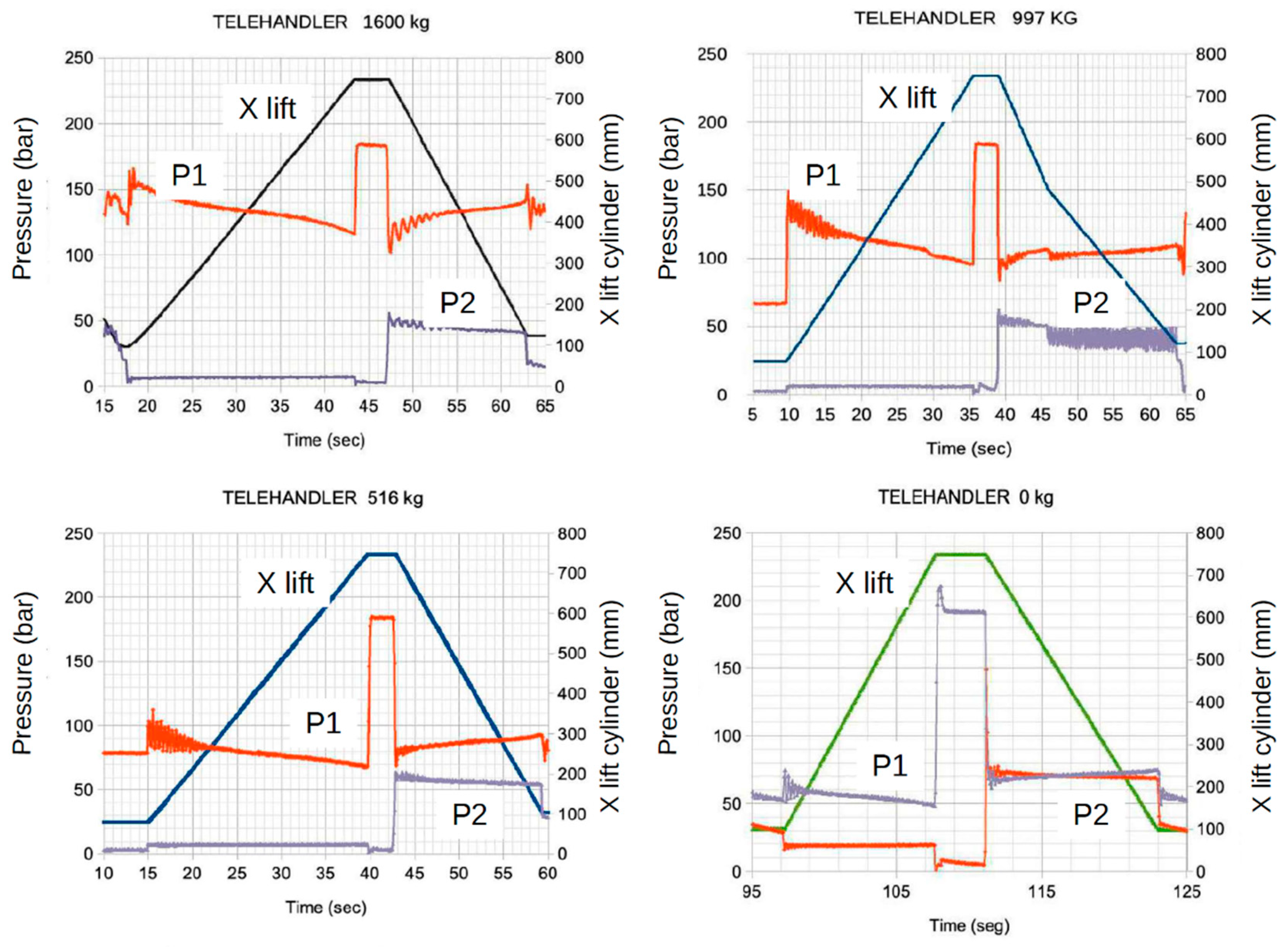
Figure 21.
Operating values of the overcentre valve during the upward and downward movement of the lift arm for four load conditions.
Figure 21.
Operating values of the overcentre valve during the upward and downward movement of the lift arm for four load conditions.
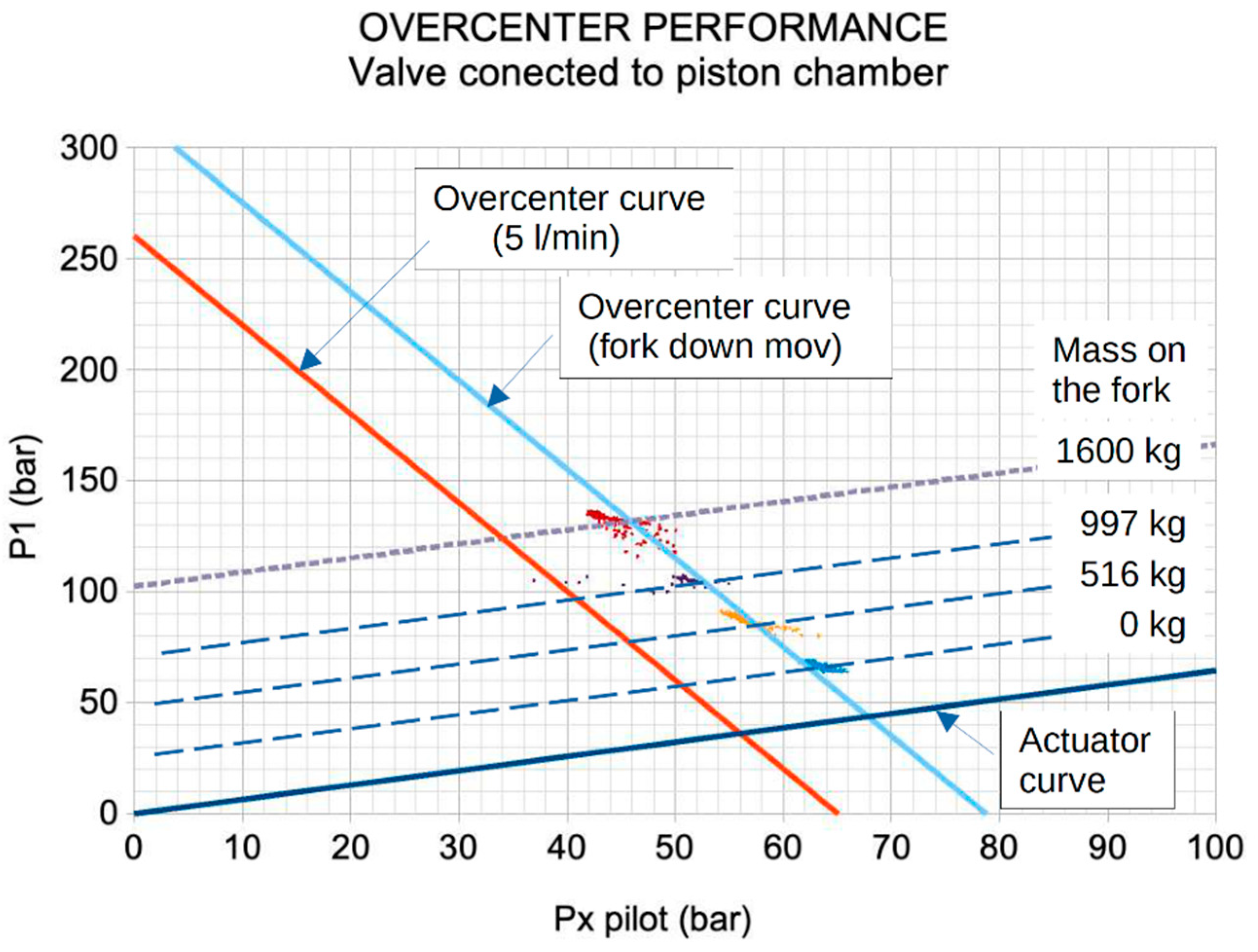
Figure 22.
Evolution of the fork leveling angle as the boom moves downward.

Figure 23.
Ground reaction forces experimental and numerical during test: lifting and lowering a 640 kg mass: a) extension in position A and boom lifting; b) extension in position A and boom lowering; c) extension in position E and boom lifting; d) extension in position E and boom lowering.
Figure 23.
Ground reaction forces experimental and numerical during test: lifting and lowering a 640 kg mass: a) extension in position A and boom lifting; b) extension in position A and boom lowering; c) extension in position E and boom lifting; d) extension in position E and boom lowering.
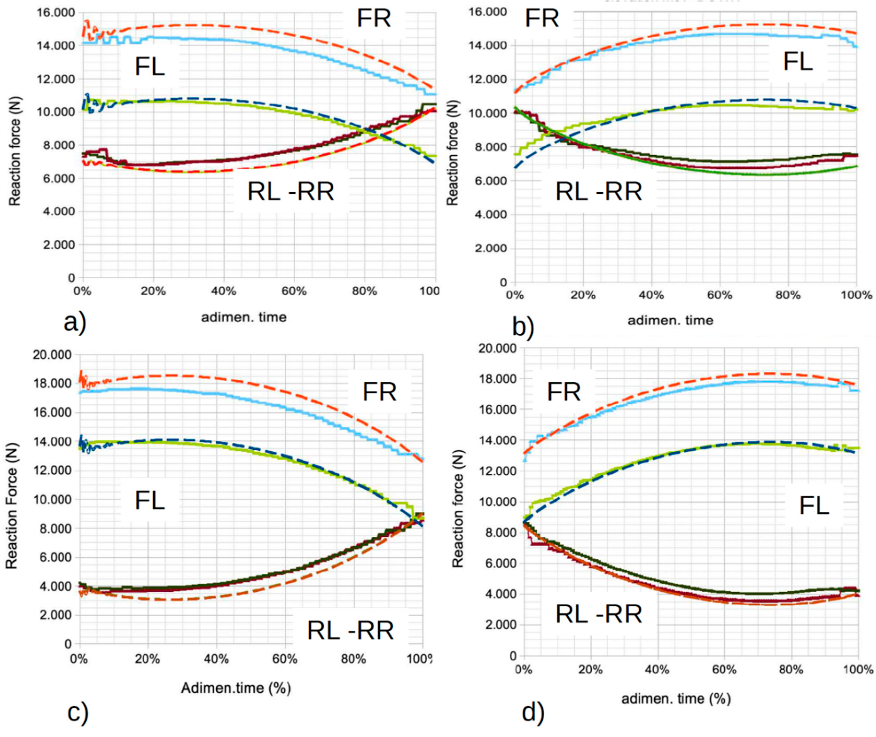
Figure 24.
Percentage difference between numerical values and experimental results: a) left: Extended arm Position A; b) right: Extended arm Position E.
Figure 24.
Percentage difference between numerical values and experimental results: a) left: Extended arm Position A; b) right: Extended arm Position E.
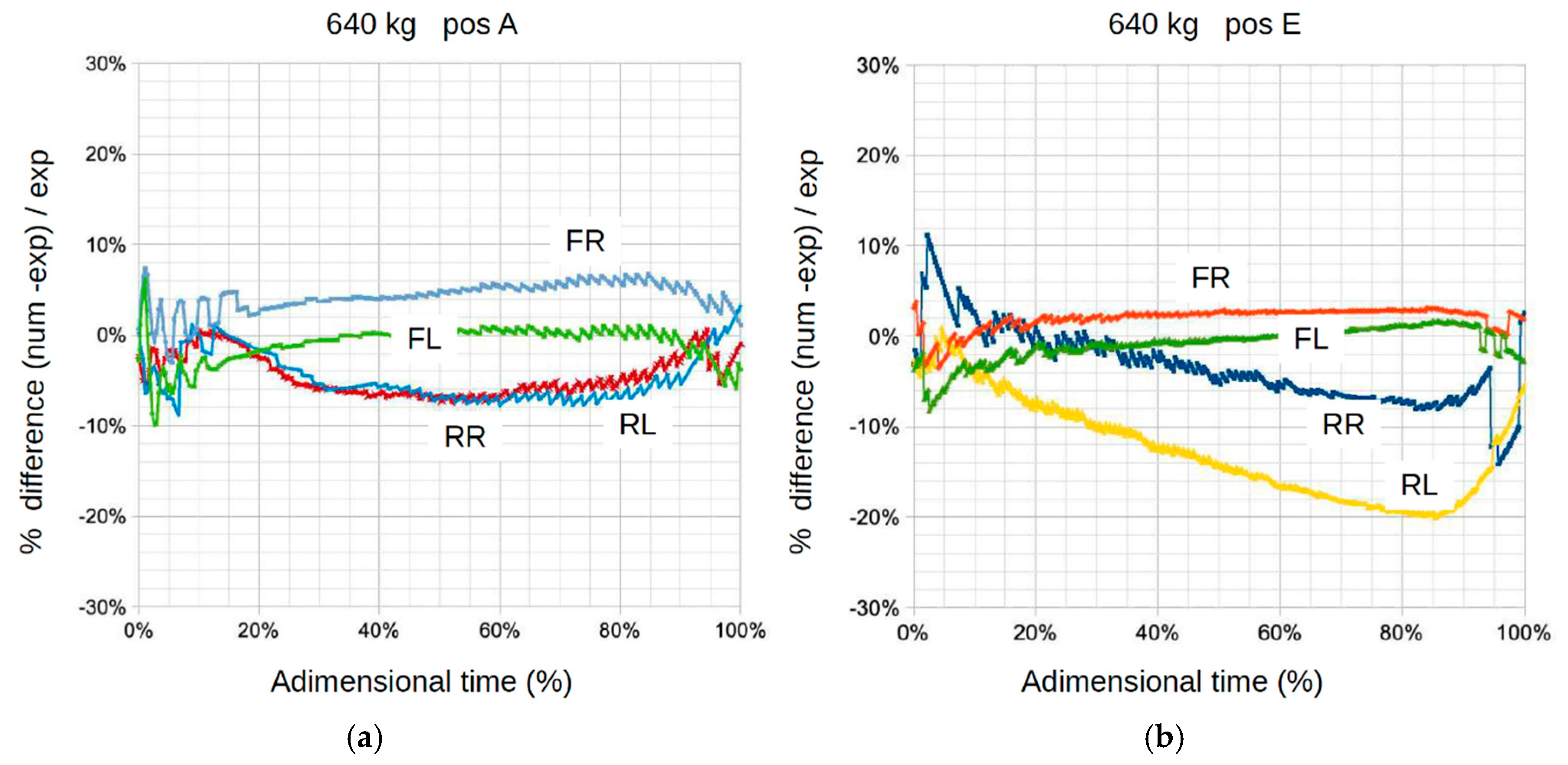
Figure 25.
Ground reaction forces as a function of extension telescopic position and mass 640 kg on the fork. (The solid line corresponds to experimental values, and the dashed line corresponds to numerical values).
Figure 25.
Ground reaction forces as a function of extension telescopic position and mass 640 kg on the fork. (The solid line corresponds to experimental values, and the dashed line corresponds to numerical values).
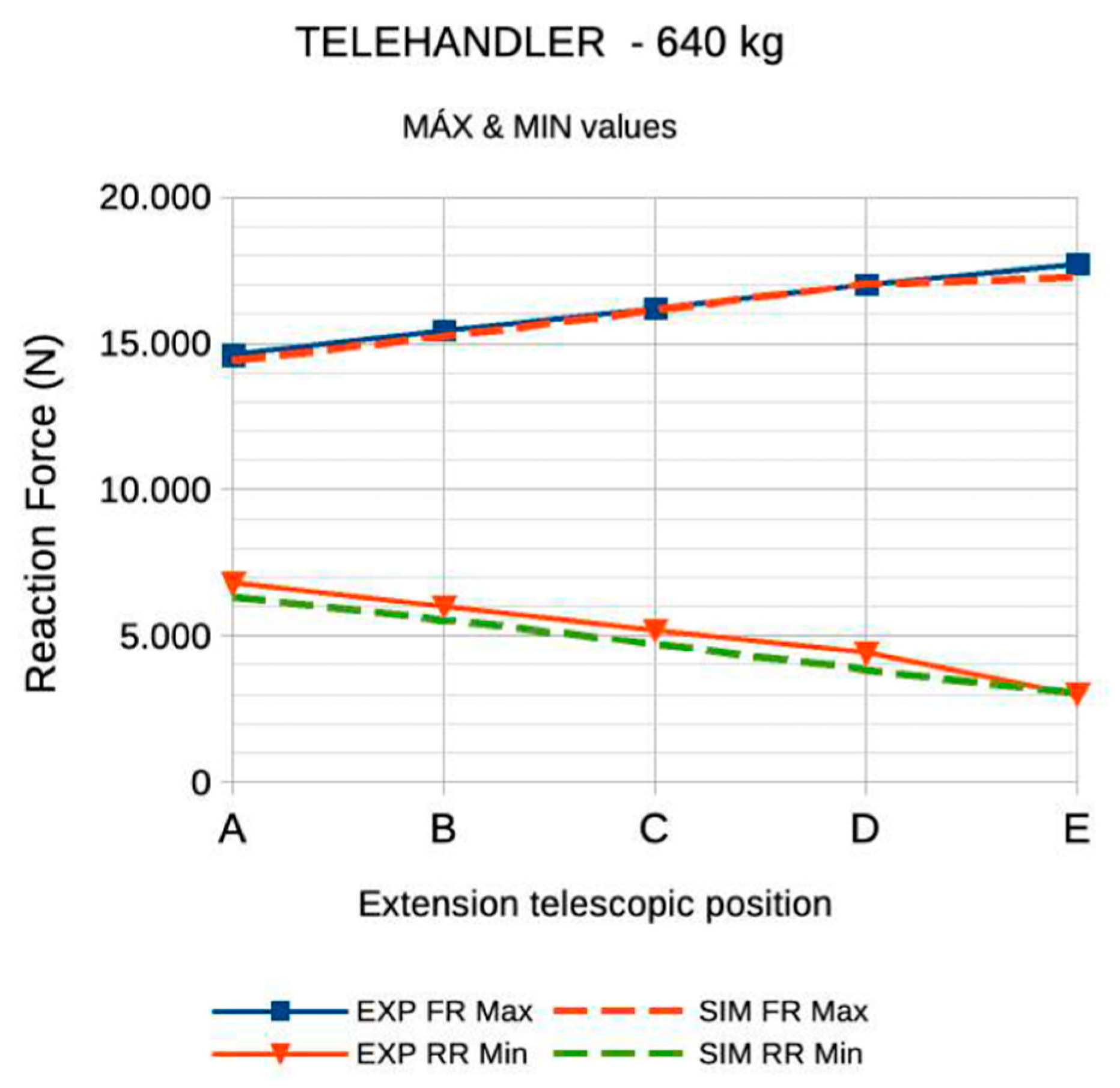
Figure 26.
Numerical values and experimental results of fork self-leveling.
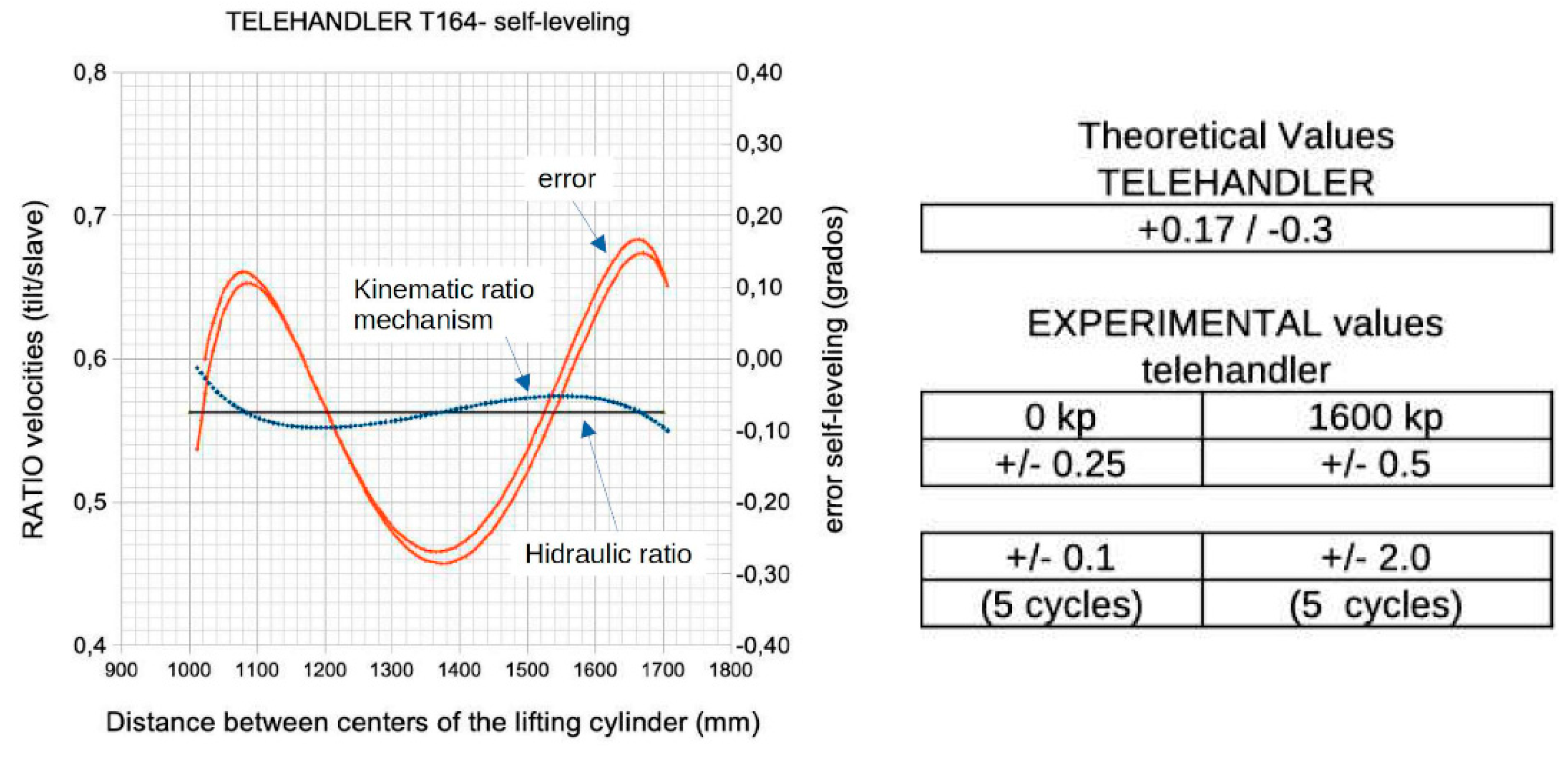
Figure 27.
Experimental values of the tire stiffness.
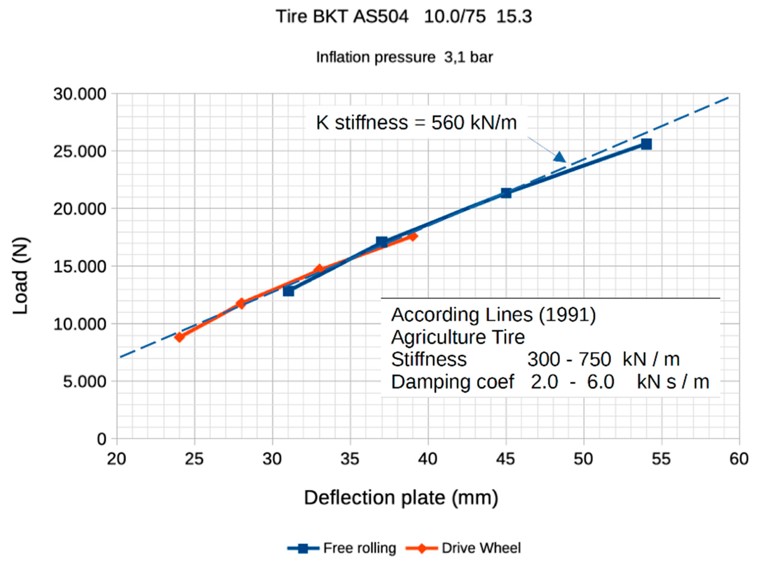
Figure 28.
Numerical results of the simulation of the vertical motion of the tire's centre of mass. (a) for different values of the tire stiffness; (b) for damping coefficient = 1 kN s/m;.
Figure 28.
Numerical results of the simulation of the vertical motion of the tire's centre of mass. (a) for different values of the tire stiffness; (b) for damping coefficient = 1 kN s/m;.
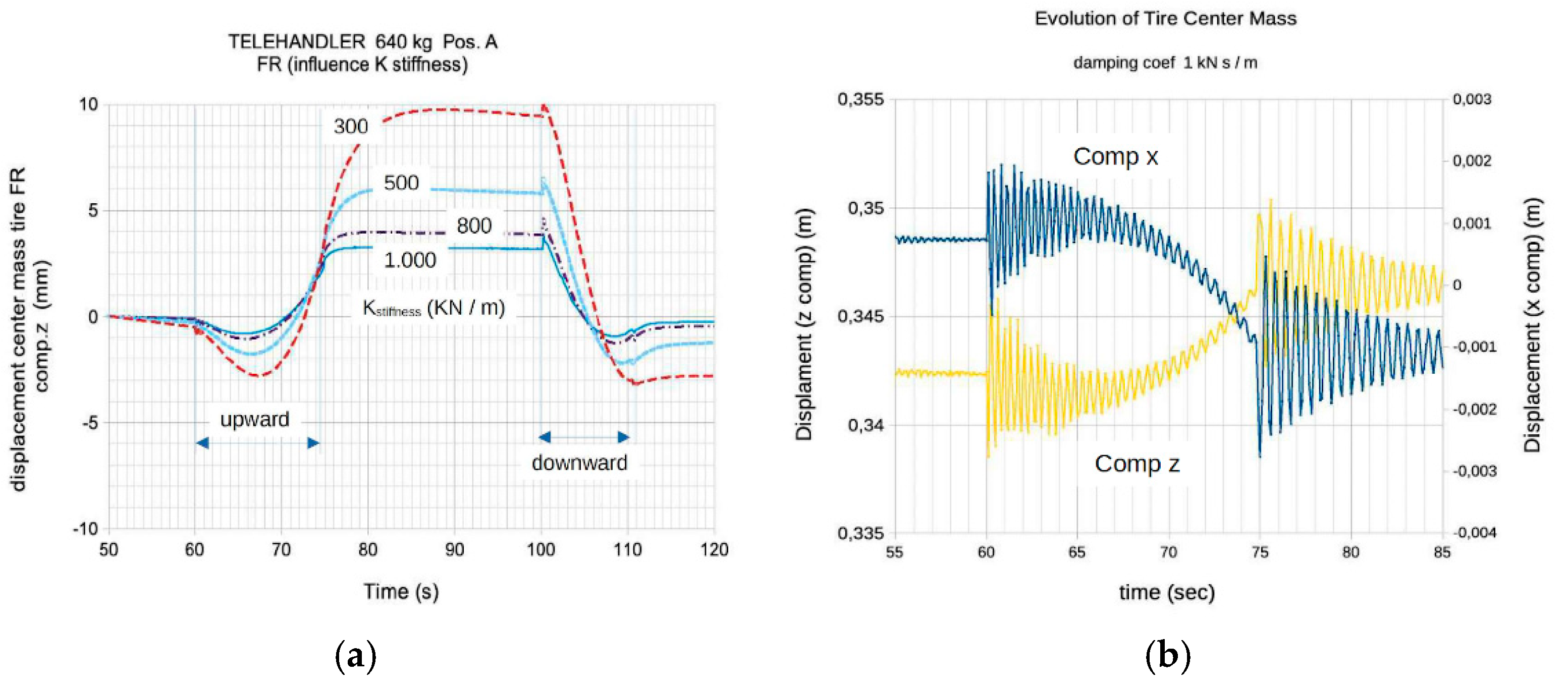
Table 2.
Different Category and Simulation Software Platforms.
| Software Codes Categories: | |
|---|---|
|
Category «A» The first category consists of general-purpose programs for the analysis and simulation of multibody systems, which can be further divided into two major groups: | |
|
Group 1 These programs are designed specifically for the simulation of multibody system dynamics, such as ADAMS, SIMPACK, RECURSIM, ALTAIR Motion Solve, Samcef Mecano, etc. They are often integrated into large platforms or portfolios for the simulation of complex multiphysics systems, such as HEXAGON, 3DEXPERIENCE, ALTAIR etc. There is a growing trend of strategic partnerships between these software providers to collaborate in the integration of their technologies and offer joint solutions to their clients. |
Group 2 Initially focused on the dynamic analysis of physical and/or multidomain systems. These programs eventually expanded their capabilities by incorporating methods and tools for modelling of multibody systems (Bond Graph codes are also included). Examples are MODELICA (Dymola, SimulationX), SIMCenter AMESSim, MAPLESim, 20 SIM, etc.. Dymola, along with its multibody library, offers efficiency and ease-of-use that is comparable to commercially available multibody programs. The openness of Modelica means a support from lots of different tools (free and commercial). |
|
Category «B» As an alternative, there is a second category of software codes that remain within the university and research center environments where they were developed. Unfortunately, these tools are not widely known. The advantage of these tools is that normally they are open source, allowing the community of users to adapt them according to their specific needs. Examples of such tools include FreeDyn, EasyDyn, MBSLIM, etc. Additionally, specific physical aspects of multibody systems have been modeled, including high pairs of joints, complex friction models, and flexible bodies. | |
Table 3.
Multi-solid model and main geometric and dynamic parameters.
| CM (m) | MOMENT OF INERTIA, IIG (kg m2) | |||||||
| RIGID BODY | DENOMINATION | MASS (kg) | x | y | z | IIG1 (kg m2) | IIG2 (kg m2) | IIG3 (kg m2) |
| Left front wheel | RB1 | 40,0 | 0,000 | 0,628 | 0,360 | 1,0 | 1,0 | 2,2 |
| Right front wheel | RB2 | 40,0 | 0,000 | -0,628 | 0,360 | 1,0 | 1,0 | 2,2 |
| Left rear wheel | RB3 | 40,0 | -1,750 | 0,628 | 0,360 | 1,0 | 1,0 | 2,2 |
| Right rear wheel | RB4 | 40,0 | -1,750 | -0,628 | 0,360 | 1,0 | 1,0 | 2,2 |
| Platform (motor, axle, cardan, transfer box, oil tank, xasis) | RB5 | 2096,0 | -1,250 | 0,014 | 0,710 | 121,0 | 1032,0 | 1085,0 |
| Rear axle | RB6 | 113,0 | -1,741 | 0,010 | 0,362 | 0,8 | 12,6 | 12,6 |
| Boom | RB7 | 147,0 | -0,809 | -0,476 | 1,130 | 37,5 | 37,5 | 3,0 |
| Mobile boom | RB8 | 165,0 | -0,203 | -0,383 | 0,927 | 76,0 | 76,0 | 6,4 |
| Attachment (tablier, rocker, two forks) | RB9 | 178,0 | 0,938 | 0,000 | 0,102 | 2,0 | 2,0 | 3,5 |
| Load | RB10 | 640,0 | 1,177 | 0,000 | 0,514 | 266,0 | 266,0 | 266,0 |
| Housing lift cylinder | RB11 | 25,5 | -0,805 | -0,476 | 0,858 | 1,5 | 1,5 | 0,2 |
| Piston lift cylinder | RB12 | 25,5 | -0,805 | -0,476 | 0,858 | 1,5 | 1,5 | 0,2 |
| Housing compensation cylinder | RB13 | 9,0 | -1,325 | -0,476 | 1,079 | 0,3 | 0,3 | 0,1 |
| Piston compensation cylinder | RB14 | 9,0 | -1,325 | -0,476 | 1,079 | 0,3 | 0,3 | 0,1 |
| Housing flip cylinder | RB15 | 14,5 | 0,250 | -0,260 | 0,611 | 0,3 | 0,3 | 0,1 |
| Piston flip cylinder | RB16 | 14,5 | 0,250 | -0,260 | 0,611 | 0,3 | 0,3 | 0,1 |
| Housing steering cylinder | RB17 | 6,5 | -1,872 | 0,000 | 0,439 | 0,3 | 0,3 | 0,1 |
| Piston steering cylinder | RB18 | 6,5 | -1,872 | 0,000 | 0,439 | 0,3 | 0,3 | 0,1 |
| Left steering rod | RB19 | 2,0 | -1,872 | 0,412 | 0,439 | 0,1 | 0,1 | 0,1 |
| Right steering rod | RB20 | 2,0 | -1,872 | -0,412 | 0,439 | 0,1 | 0,1 | 0,1 |
| Left carrier | RB21 | 3,0 | -1,787 | 0,455 | 0,450 | 0,5 | 0,5 | 0,2 |
| Right carrier | RB22 | 3,0 | -1,787 | -0,455 | 0,450 | 0,5 | 0,5 | 0,2 |
Table 4.
Hidraulic parameters.
| Table (hydraulic parameters) | Value | Units |
|---|---|---|
| Oil density | 875 | kg/m3 |
| Oil bulk modulus | 17.500 | bar |
| Oil kinematic viscosity | 46 | cSt |
| Pump maximum displacement | 12 | cm3/rev |
| Pump volumetric efficiency | 0,93 | |
| Pump hydraulic–mechanical efficiency | 0,96 | |
| Relief valve cracking pressure | 210 | bar |
| Overcenter valve ratio (CEB) (*) | 4 : 1 | |
| Overcenter pressure setting | 275 | bar |
| Directional control valve block (*) | 202 | serie |
| Viscous friction coefficient | 50 | N/m/s |
| Cylinder leakage coefficient | 0,01 | l/min / bar |
| Piston diameter of the boom hydraulic cylinder | 100 | mm |
| Rod diameter of boom hydraulic cylinder | 55 | mm |
| Travel of boom hydraulic cylinder | 689 | mm |
| Piston diameter of the extension hydraulic cylinder | 60 | mm |
| Rod diameter of extension hydraulic cylinder | 40 | mm |
| Travel of extension hydraulic cylinder | 1.239 | mm |
| Piston diameter of the fork hydraulic cylinder | 100 | mm |
| Rod diameter of fork hydraulic cylinder | 60 | mm |
| Travel of fork hydraulic cylinder | 268 | mm |
| Piston diameter of the slave hydraulic cylinder | 75 | mm |
| Rod diameter of slave hydraulic cylinder | 45 | mm |
| Travel of slave hydraulic cylinder | 344 | mm |
| Engine power | 19 | kW |
| Torque | 92,6 /1700 | Nm /rpm |
| Engine speed | 2.300 | rpm (max) |
(*) The geometric parameters of hydraulic components have been determined experimentally in lab but we cannot disclose the values as they are proprietary to the manufacturers.
Table 5.
E Data acquisition and processing equipment.
| Instrumentation | Characteristics | Reference |
|---|---|---|
| Position: 2 inclinometers |
2 inclinómetros (I), to measure fork leveling -45º to 45º and 4 to 20 mA | SICK TMM55E-PMH045 |
| 3 extensometers (X), to measure boom extension. 0 to 1500 mm and 0 to 10V | Micro epsilon, WDS-1500-P60-SR-U | |
| Accelerometers: 7 accelerometers |
7 lineals accelerometers 3 axis, range 3g and 6g | SparkFun, Triple Axis Accelerometer - MMA7260Q (6g) / Analog devices, ADXL335 Small, Low Power, 3-Axis ±3 g |
| Loading: 2 weighing equipments |
2 Electronic weighing system amb visor. Weigh vehicle's axles and total weight. Composed of two portable platforms of the WWS series and weighing terminal with touch screen and integrated printer. |
DINI ARGEO USBCKR-1, portable kit. Wired version. |
| Flow: 1 flowmeter |
A flowmeter (Q) 0 to 300 liters/min., 4 to 20 mA | HYDAC EVS 3100-A-0300-000 |
| Pressure: 13 pressure transducers (P) |
13 pressure transducers (P) of two types: 3 of 0-400 bar and 10 of 0-250 bar. 4 to 20 mA | WIKA, MH3 with connector M12 |
| Temperature: 1 sensor (T) |
A PT 100 (T) temperature sensor and temperature transmitter (converts PT100 signal to a 4 to 20 mA electrical signal). Temperature transmitter ranges: 0 to 250ºC and 4 to 20 mA | Temperature transmitter model: Wika T20.10.100 |
| Other analog signals | Analog input signals of Delta Equipment: Voltage signal from 0V at low level and 10V at high level | 3 Triggers: for the National Instruments Equip., for the load cell and for the 3-way flow regulating valve solenoid signal. |
Table 6.
List of sensors used.
| Experimental Equipment | Characteristics | Reference |
|---|---|---|
| Equipment 1 data acquisition | Equipment for accelerometer signals data acquisition | NATIONAL INSTRUMENTS USB-6343 |
| Laptop 1 | LABVIEW for acquisition of accelerometer signals | LabVIEW 2021 and NI software |
| Equipment 2 data acquisition | Data acquisition from hydraulic, position and temperature transducers and sensors. | DELTA RMC200 |
| Laptop 2 | DELTA RMC Tools Software for acquisition signals from pressure, flow, temperature, and position sensors. | DELTA RMC Tools Software |
| Laptop 3 | To acquire data from the rear axle load cell of machine | |
| Digital camera | To record videos | SONY RX100 IV |
Disclaimer/Publisher’s Note: The statements, opinions and data contained in all publications are solely those of the individual author(s) and contributor(s) and not of MDPI and/or the editor(s). MDPI and/or the editor(s) disclaim responsibility for any injury to people or property resulting from any ideas, methods, instructions or products referred to in the content. |
© 2024 by the authors. Licensee MDPI, Basel, Switzerland. This article is an open access article distributed under the terms and conditions of the Creative Commons Attribution (CC BY) license (http://creativecommons.org/licenses/by/4.0/).
Copyright: This open access article is published under a Creative Commons CC BY 4.0 license, which permit the free download, distribution, and reuse, provided that the author and preprint are cited in any reuse.


