
Submitted:
27 September 2024
Posted:
29 September 2024
You are already at the latest version
Abstract
This paper presents the development and testing of the passive Almaty Ankle Exoskeleton V.2. The device features a new design with three electric linear actuators, and the shin and foot platforms are connected by links with spherical and universal joints. Functional testing demonstrates the prototype's ability to operate effectively within the natural range of ankle joint movements. Preliminary results indicate that the exoskeleton can reduce calf muscle activation in the work limb where the device is applied. In this the passive exoskeleton is designed for dorsiflexion and plantarflexion, whose operation with numerical results is highlighted by focusing on parameters such as angular velocity, linear acceleration, and angles. These measurements provide valuable information about the exoskeleton's performance and efficiency.
Keywords:
Ankle Exoskeletons
; Design
; Performance
; Experimental evaluation
; Almaty Ankle Exoskeleton V.2
1. Introduction
The ankle joint is a complex joint that forms a kinematic link between the lower limb and the foot, allowing motions for daily tasks. It experiences high compressive and shifting forces during walking, but due to its structure it functions with a high degree of stability. Unfortunately, this joint is very susceptible to acute and long-term injuries in physically active people. Thus, there is a need for rehabilitation to restore full function of the damaged joint [1,2,3].
To solve the above-mentioned problems, researchers have explored the field of robotics for the rehabilitation of the ankle. Traditional rehabilitation therapy is mainly based on individual treatment by rehabilitation trainers, which has such drawbacks as low efficiency and high labor intensity [4].
To counteract these aspects and to improve the quality of rehabilitation in recent years, rehabilitation therapy has been involving robotic system. These robots are designed to improve the locomotor function of the ankle joint.
Robotic systems are used in clinics to recover from stroke and ankle injuries, but their use is limited, and they are very expensive. Prices range from $75,000 to $350,000. These high costs make people think that robots are too expensive for both healthcare systems and individuals [5,6].
Platform robots are basic-stationary, and the foot is connected to a mobile platform and usually uses a parallel mechanism to perform ankle movements. Stationary systems have been developed for more than 20 years, starting in 1999 [7].
Most previous robotic designs are based on a static platform, where an immobile device requires the patient to keep their foot on a grounded platform (usually in a seated position) to perform rehabilitation, which is inconvenient for home use [8,9,10,11,12,13,14,15,16,17,18]. These devices are not only bulky but also fixed in place. As a result, patients must visit a hospital or facility where the rehabilitation equipment is installed, despite potential mobility impairments.
In [8] the authors developed an exoskeleton using 3D printing technology from a PLA material. Exoskeleton is intended to improve the rehabilitation of the ankle joint through three degrees of freedom. The design uses an Arduino Uno controller to control the motors and sensors. The exoskeleton is programmed to work at low speeds, which limits the range of movement compared to a normal human and can reduce the effectiveness of rehabilitation.
In the work [9], the authors presented a robotic platform for ankle rehabilitation, equipped with 6 actuators powered by IBL3605A motors from Tech Servo Co. Ltd., Shenzhen, China. These actuators provide a semi-closed loop for position control and communicate with a PC-104-based personal computer via a CAN bus for efficient system management. The developed exercise modes, including constant speed, constant torque, and awareness, are suitable for various stages of rehabilitation and demonstrate an innovative approach to comprehensive body training. The current control system uses a mouse and keyboard for user input, but it lacks a more user-friendly interface that could improve overall user experience.
The device described in [10] is characterized by complexity and high cost due to the use of mechanical transmissions for motion conversion. Additionally, a limitation is the need for external fluid sources for pneumatic or hydraulic actuators, which is not always feasible for home use. The control system uses linear and rotary actuators, along with additional mechanical transmissions to activate prismatic joints. The rehabilitation device is too complex and requires the presence of a physical therapist, as well as being too expensive for home use. Such a system can be tedious and exhausting, reducing patient motivation for regular use.
Described in [11] is the PKAnkle robot, whose controller includes a force and torque sensor installed under the sole and an EMG signal map with eight control channels. The position and alignment of the drives of wearable devices can create in-ternal forces in the ankle not directly related to real movements, that can mislead a patient’s protraction during rehabilitation. The prototype causes unwanted internal forces in the ankle due to incorrect positioning and alignment of the drives, which can also mislead the coupling. PKAnkle wearables require precise ergonomic design besides to be lightweight, comfortable and suitable for a wide range of anatomical features.
The exoskeleton designs in [12] and [13] present challenges: [12] highlights issues with increased inertia and limited motor placement in serial mechanisms, while [13] emphasizes difficulties in controlling force and position due to environmental variability, requiring advanced control strategies for effective ankle rehabilitation.
The parallel mechanism of the exoskeleton [14] provides high load capacity and flexibility but has limited working space and complex constraints, which reduces effectiveness and accuracy during rehabilitation.
One of the main drawbacks of rehabilitative robotics is the difficulty in teaching medical personnel how to work with a robot. Robot in [15] in rehabilitation clinics are very expensive and have limited functionality due to manufacturer’s limitations. The exoskeleton control system is implemented using the component intermediate software Orocos. The prototype has a limited range of motion, allowing only two degrees of freedom and one progressive degree of freedom, that can limit the kinds of exercises for ankle rehabilitation. Although the software architecture is modular, it can create problems with programming and configuration for different patients or exercises. Reliance on component software such as Orocos [15] can lead to potential compatibility problems or limitations in the long run.
Exoskeleton design in [16] involve mechanical joint restrictions that limit the range of motion and require design adjustments for patient safety, with a drive system of linear drives and a stepper motor, but face challenges in movement range, weight, and cost.
The exoskeleton design in [17] faces issues with excessive strain on the patient’s ankle, high development costs, and complexity, with limitations in personalized treatment and adaptability to various ankle conditions, potentially affecting service and durability.
Structures described in [18] may encounter maintenance and repair issues due to their complexity, with limitations in degrees of freedom affecting adaptability, precision, and stability. The exoskeleton uses a stepper motor and adaptive impedance control but faces challenges with movement flexibility, rotation centering, and overall operation.
From the described designs of robotic ankle rehabilitation platforms, the following significant deficiencies can be identified:
- −
- Limited range of movements: Many prototypes have limited range of movements, which can negatively affect the effectiveness of rehabilitation. For example, parallel mechanisms often have limited workspace, which limits the types of exercise for patients.
- −
- Complexity of management and learning: Systems require complex management and programming strategies that complicate the training of medical personnel and implementation into clinical practice. This creates a barrier to widespread use in rehabilitation institutions.
- −
- High cost and complexity: Many robots are expensive and require complex engineering, making them inaccessible for home use and daily clinical practice due to budget constraints.
- −
- Problems with proprioception and physiological aspects: Several designs may create unnatural sensations or strain the patient’s foot, making rehabilitation difficult and may mislead proprioception.
- −
- Individual anatomical and functional features: not all systems consider the individual characteristics of patients, which reduces their effectiveness.
- −
- Durability problems with regular use: Wearable designs face durability problems that require additional maintenance costs.
All these challenges require further efforts to improve the availability, efficiency and usability of robotic ankle rehabilitation platforms in both clinical and home settings.
They not only save money, but they also help to better use resources. Robotic exoskeletons can be an attractive means of rehabilitation, not only for restoring motor activity, but also to increase physical activity years after an injury [19]. Using robots at home brings many benefits, including saving money and time on treatment. The home-grown portable robotic exoskeleton can do all the movements that you get in a rehabilitation center.
The exoskeleton devices for the ankle joint are wearable human-machine integrated mechanical devices, which are usually anthropomorphically designed to provide active and passive help to users [20].
Exoskeleton devices for ankle rehabilitation show significant promise in improving clinical evaluation, The United Nations High Commissioner for Human Rights has been working to ensure that the United Nations system is able to provide effective and timely rehabilitation.
However, problems such as size limitations, long-term efficiency, comfort issues, and mechanical complexity must be addressed through constant research and innovation. Future developments should be aimed at improving the usability of devices, Clinical applicability is extended through large-scale research and design optimization to improve patient comfort and safety.
The aim of this work is to develop a compact device for rehabilitation of the human ankle. A new of this work is the development of a device with a purely mechanical mechanism, made of materials available on the market. The proposed for rehabilitation of the ankle joint. It is designed for convenient use by patients and physiotherapists. The system is simple, reliable and easy to use. This paper reports experiences towards an improved version of Almaty Ankle Exoskeleton V.2.
2. Materials and Methods
This section outlines the methodology used in the development of the proposed rehabilitation device. Initially, it was necessary to identify issues in the design of V1, with particular attention to the requirements for the Almaty Ankle Exoskeleton V.2. A CAD model with three degrees of freedom was then developed, and a prototype was created using 3D printing. The final stage involved testing the models of the Almaty Ankle Exoskeleton V.2 and conducting functional tests of the device, followed by a comprehensive discussion of the results obtained.
2.1. Problems in Design V1
Figure 1b shows the prototype of the Almaty Ankle Exoskeleton V.1, equipped with four electric linear actuators, while Figure 1a presents its kinematic design [21]. The use of these actuators increases the total weight and size of the exoskeleton, making it less convenient for long-term use for rehabilitation purposes. In addition, the four electric linear actuators require more power, which complicates the control system due to the need to control the engines and related electronics. In general, the main drawbacks of the Almaty Ankle Exoskeleton V.1 with four electric linear actuators are complex control system and large dimensions, which leads to inconvenience.
The Actuonix L16 linear actuator [23] is a popular choice for various applications, including our exoskeleton. However, certain drawbacks were identified during experiments. These issues were particularly evident during ankle testing, where precision and reliability were critically important, as described in [24]. Some of the drawbacks and problems associated with the Actuonix L16 linear actuator were identified during the experiment. The Actuonix L16 linear actuator has several limitations:
- Limited Load Capacity: The actuator’s load capacity is insufficient for applications requiring higher output power, such as supporting and activating the ankle under dynamic conditions.
- Speed: The speed of the L16 linear actuator is not high enough for applications that require quick and responsive movements, which is critical for effective rehabilitation.
- Accuracy: The L16 linear actuator does not provide the necessary accuracy, impacting the effectiveness of the exoskeleton in delivering precise ankle care and support.
- Power Consumption: The power consumption of the L16 is high, which affects the overall energy efficiency of the system.
Figure 2 shows the main components of the Almaty ankle exoskeleton version 1. The model has several potential drawbacks, including a power supply that requires connection to a personal computer (PC) to control all devices. The bulkiness and lack of portability of the device reduce the system’s convenience and mobility. Managing multiple components complicates the setup of the exoskeleton. Users may encounter difficulties in assembling and operating the system without technical assistance, making it less accessible for non-specialists. The need for multiple connections between the power supply, personal computer, and control unit leads to tangled wires, increasing the risk of failures and reducing ease of use. Dependence on an external power source limits the mobility of the exoskeleton. Users will always need access to an electrical outlet, restricting its use to indoor environments or areas with a reliable power supply, which diminishes its practical utility in real-world applications. The presence of a power supply also poses potential safety risks, such as electric shock or short circuits, especially if the equipment is not properly insulated or maintained. Using multiple components increases the likelihood of system failure. A malfunction in just one component can render the entire system inoperative. Using a personal computer for control also leads to high energy consumption. This reduces the system’s overall energy efficiency and can make it more expensive to operate over time due to increased power usage. Users will require specialized training to properly operate and maintain the exoskeleton, which could become a significant obstacle for individuals without a technical background.
Figure 3 shows the mechanical design of the prototype, which has several significant shortcomings that have affected its performance, usability, and safety. The rigid foot platform causes discomfort for the user. Insufficient adaptation to the natural movements of the ankle joint can lead to discomfort, inefficient support during movement, and even potential injuries.
The thin plastic strap securing the foot in the exoskeleton would slip and shift, reducing control and increasing the risk of injury. The combination of a rigid platform and unreliable foot fixation increases the risk of falling due to inadequate support and possible slippage. The rigid design unevenly distributes pressure on the foot, which, as experiments have shown, causes discomfort during prolonged use.
The foot platform does not allow for easy adjustment according to the individual needs of users. Each person may require different levels of fit or support, and the current design does not always accommodate these requirements.
2.2. Requirements
The requirements for the Almaty ankle exoskeleton V.2 were developed based on the experience with version V.1: first, the design should use lightweight materials to reduce the overall weight of the exoskeleton and improve user comfort. It is necessary to create a more compact and ergonomic design that minimizes bulkiness and enhances user mobility during rehabilitation.
- -
- Improved degrees of freedom for better simulation of natural ankle movement, improving functionality.
- -
- The exoskeleton should easily adapt to the different anatomical features of the user with minimal changes.
- -
- Introduction of energy efficiency components and mechanisms to reduce energy consumption.
- -
- Improved control system to ensure accuracy of movement and responsiveness.
- -
- Enable security mechanisms to protect the user in case of system failures or malfunctions.
- -
- The design should be easy to maintain, with accessible components that can be quickly maintained or replaced.
- -
- Development of an auxiliary device for movement with introduction of possibilities of monitoring the condition of the ankle during rehabilitation.
Considering the limitations of the first prototype, the second version will be compact, and all components will be minimized.
Firstly, the use of actuators with higher load capacity and output power will be considered. This will ensure that the actuators can handle the dynamic loads encountered during rehabilitation. The actuators should offer greater speed and responsiveness to improve the exoskeleton’s performance. It is important to choose actuators known for their reliability and long service life to reduce maintenance needs and ensure dependable operation over time. Additionally, actuators designed with energy efficiency in mind are essential since the V.2 exoskeleton will be powered by batteries. Addressing these aspects will help enhance the performance and reliability of the ankle exoskeleton, making it more effective and user-friendly.
A more compact and integrated power solution, such as battery packs, will be developed to improve mobility and convenience. To increase durability and performance, more robust materials like lightweight PLA plastic will be used.
The platform will include flexible elements that better adapt to the natural movements of the ankles and enhance comfort. A mounting mechanism with adjustable straps and foot supports will also be added to ensure a stable and snug fit.
Addressing these issues will significantly improve the Almaty Ankle Exoskeleton V.2 in terms of durability, user comfort, safety, and overall effectiveness.
2.3. Design Solution
Figure 4a shows the kinematic design, and Figure 4b presents the CAD model of the Almaty Ankle Exoskeleton V.2, a wearable device designed to support ankle joint movements. The proposed solution features a parallel mechanism with electric linear actuators, as the Almaty Ankle Exoskeleton V.2. The tibia platform is located below the knee and can be adjusted to fit the patient’s leg size. A key feature of the device is the sole, made from PLA plastic, ensuring its durability during rehabilitation. The electric linear actuators are equipped with spherical and universal joints that connect the tibia platform to the sole, as shown in Figure 5.
The Exoskeleton V.2 is designed to be attached to the tibia, facilitating ankle mobility. Its design includes an electric linear servomotor, which converts linear motion into the force needed for the exoskeleton’s operation. This force helps support the user’s ankle during movement, enhancing mobility and reducing joint strain.
Figure 6 shows the view of the CAD project with the main components of Almaty Ankle Exoskeleton V.2:
- −
- The tibia body 1 is a shank platform that is shaped to provide a reliable and convenient fit for the user, and at the same time serves as a basis for fixing components that contribute to the functionality of the exoskeleton.
- −
- The angle joints 2 and 11 are designed to connect the actuator to tibia a platform that holds the tibia during movement in the ankle joint.
- −
- The connection 4 is intended for fixing a linear actuator to angular hinge joints.
- −
- The linear actuator 3, 5 and 12 provides controlled linear motion to perform certain movements that facilitate ankle function during rehabilitation.
- −
- 6 is the internal contour of the Actuator, which provides the force to create movement in the actuator.
- −
- The universal hinge 7, 8, and 13 is designed to connect the actuator to a platform that holds the feet together, allowing for smooth, rotational movement of the foot.
- −
- The foot housing 9 is a foot platform designed to accommodate the foot of the user. It secures the foot in the exoskeleton, ensuring correct position and stability during exercise.
- −
- The mounting brackets 10 for the shank platform are designed according to the specified size.
- −
- 14 is a Velcro strap that effectively transfers the load to the ankle.
Figure 7 shows the CAD design with dimensions of the mechanical solution for the Almaty Ankle Exoskeleton V.2. The ankle exoskeleton includes attachments between the foot (AB) and the thigh (CD) using ball and universal joint elements.
Linear actuators S1, S2, and S3 are installed at the front and back of the ankle. The electric linear actuator features a system that synchronizes the movement of the two interconnected parts of the exoskeleton and moves the ankle along with the exoskeleton. All dimensions of the Almaty Ankle Exoskeleton V.2 are listed in Table 1.
2.4. Prototype
The housings for the ankle exoskeleton were 3D printed using a Flash Forge Adventure 5 printer. The foot and shank platforms, made from PLA plastic, are strong and rigid, making them suitable for use as structural components of the exoskeleton.
The printing process is shown in Figure 9: the Foot platform was printed in 2 hours and the Shank platform in 45 minutes.
Figure 10 shows an electric linear actuator that converts rotational motion into linear motion, allowing precise adjustment of distance and speed. The electric linear actuator has the following specifications: IP54 protection class, 150 mm stroke length, 12 V operating voltage, 1.5 cm/s speed, and 50 kg load capacity [25].
A spherical joint is attached to the upper part of the actuator to connect the rod with the support ring, while a universal joint is attached to the lower part, as shown in Figure 10a and b.
Advantages of using this linear actuator for the exoskeleton of the ankle joint:
- −
- Precise motion actuator provides control over the movement of the ankle, which is necessary to achieve natural and smooth movement. This accuracy helps to mimic the natural cycle during rehabilitation.
- −
- The adjustable drive speed of up to 1.5 cm/s ensures controlled and consistent movement, ensuring that the exoskeleton will respond adequately to user needs.
- −
- Support and stability with a load capacity of 50 kg the actuator can withstand weight and force applied by the user’s foot and ankle, ensuring stability and strength. This ability ensures that the drive can cope with dynamic loads during rehabilitation.
- −
- Working from 12 V DC: the drive running from 12 V DC is compatible with standard power sources and batteries, making it energy efficient and easy to integrate into exoskeleton design. This efficiency is critical for portable devices such as exoskeletons where battery life is a critical factor.
- −
- Sensor integration: the actuator can be integrated with various sensors and control systems to create a responsive and adaptive exoskeleton.
2.5. Testing Layout
This prototype includes a motor system that targets the anterior tibialis muscle, providing tactile stimulation during active movement. It supports key movements such as dorsiflexion and plantarflexion, abduction and adduction, as well as inversion and eversion, which are essential for walking and maintaining balance.
Figure 12 shows a circuit design of a laboratory prototype of the ankle joint, which shows the connection of all the main components.
The exoskeleton is also equipped with additional wireless portable devices, as shown in Figure 13. These devices include an IMU sensor, Arduino Nano, microSD card for data recording, and a 9V battery that powers all the components. The devices will be positioned below the knee and will capture precise data on ankle joint movements, providing effective assistance to users in performing these movements.
All components of the device create a holistic system for monitoring and rehabilitation of the ankle. IMU collects detailed motion data, Arduino Nano processes this data and manages the system, the microSD card stores data for further analysis, and the switch and LED provide user interaction and feedback. Rechargeable battery ensures the device portability, allowing it to be used in a variety of circumstances: at home, in a clinic or during everyday activities. Such an approach makes it possible to effectively monitor the progress of rehabilitation, accompany patients during physical activity and provide valuable information to health workers.
This ankle measuring device combines physical support and advanced sensory technology for effective rehabilitation. It is equipped with platforms attached to the top of the ankle and foot, which provides stability and flexibility. The elastic material of the ring provides a comfortable fit, ensuring natural movement of the ankle.
During rehabilitation, the device accurately measures the movement of the ankle. These data help to assess progress, adjust rehabilitation plans and accelerate recovery. With a combination of support and technology, this device offers a comprehensive solution for ankle rehabilitation, improving recovery and function
The device is lightweight and easy to carry, which is crucial for patient comfort and ease of use during rehabilitation.
3. Results
The following sections present the test models of the Almaty Ankle Exoskeleton V.2 and the results of the device’s functional testing.
3.1. Testing Modes
Rehabilitation of the human ankle joint primarily aims to restore mobility, strength, and stability to ensure normal functional movements. Among the various movements that the ankle joint can perform, the most important are dorsiflexion and plantarflexion. These movements are essential not only for basic walking but also for more complex actions such as running, jumping, and maintaining balance.
- −
- Dorsiflexion is the movement of the foot upward toward the shin. The normal range of motion (ROM) for dorsiflexion in a healthy ankle typically ranges from 10 to 20 degrees.
- −
- Plantarflexion involves pointing the foot downward, away from the shin. The normal range of motion for plantarflexion generally ranges from 40 to 50 degrees.
In ankle joint rehabilitation, dorsiflexion and plantarflexion are critical movements that help restore normal ankle function. By focusing on these movements and their corresponding ranges, rehabilitation programs assist patients in regaining the mobility, strength, and stability needed to prevent reinjury and return to normal activities. Effective training in dorsiflexion (10-20 degrees) and plantarflexion (40-50 degrees) leads to improved gait mechanics, better balance, and the ability to perform a wide range of functional actions. Testing of the models is shown in Figure 14.
In the Almaty Ankle Exoskeleton V.2, functional testing of the device was conducted for dorsiflexion and plantarflexion, with only one actuator (S1) in operation.
The S1 actuator in the exoskeleton provides the necessary force to support or enhance ankle movement. The actuator is controlled by a joystick, which adjusts the speed and direction of movement based on the user’s actions. Figure 15 shows the laboratory device designed to control the electric actuators of the exoskeleton during rehabilitation exercises, demonstrating how the device operates:
- −
- Arduino Uno: This microcontroller acts as the main controller, sending control signals to the L298N motor driver based on programmed instructions.
- −
- L298N Motor Driver: This component receives signals from the Arduino and controls the electric linear actuator. It manages the direction and speed of the actuator.
- −
- Electric Linear Actuator: This device converts electrical energy into mechanical motion. Depending on the signals from the L298N driver, it extends or retracts.
- −
- 12V Adapter: It provides the necessary power for both the L298N motor driver and the linear actuator.
- −
- Joystick: It sends signals to the Arduino Uno, specifying the desired direction and speed of the actuator’s movement.
Thus, the Arduino Uno sends commands to the L298N driver, which then controls the movement of the linear actuator powered by the 12V adapter. This setup can be used for precise control of linear motion in various applications.
The linear actuator is controlled by a joystick, which provides a comfortable and intuitive interface. This allows for easy control of the linear electric actuator. During the joystick manipulation experiments directly matched the desired drive movement, offering a simple control method.
The use of a joystick in the ankle exoskeleton is useful in rehabilitation institutions, as patients or therapists can easily control movements such as dorsiphlexia and plantar fasciitis. This makes the process more accessible and less intimidating for those who are not familiar with complex controls. The joystick allows for instant correction of exoskeleton movements in real time, which is crucial in rehabilitation scenarios. Thus, the use of a joystick to control the linear actuator provides an accurate and responsive interface that is necessary for effective therapy.
3.2. Testing Results
The ankle motion sensor IMU of Figure 16 allows you to accurately measure and record the angular velocity and direction of joint movements. This sensor, built into the device, provides high accuracy tracking of movement dynamics, making it an indispensable tool for analysis and rehabilitation of the ankle.
Figure 17 shows the angle velocity of the ankle joint for 90 seconds of back and sole flexion. Figure 17 shows three components of angular velocity: .
The angular velocity range is -15 to 15 degrees per second. The graph also shows changes in angular velocity as a function of time, which allows to evaluate the movement dynamics of the joint during the test. Changes in angular velocity are associated with movements of the foot. The high sensitivity of the IMU sensor detects even the slightest changes in angular velocity.
Figure 18 shows the linear acceleration of the ankle joint during dorsiflexion and plantarflexion over a period of 90 seconds. The graph displays four components of linear acceleration: . The linear acceleration of the foot platform ranges from -1 to 1.5 m/s².
Figure 19 shows the angles of ankle flexion in dorsal and plantar flexion. The graph shows three components of angular motion: Roll (blue line), Pitch (blue line) and Yaw (orange line). Angle range of angles ranges from -15 to 35 degrees. The Pitch line shows significant oscillations from about -5 to 30 degrees, indicating repeated flexing movements in the back (up) and sole (down).
The second author decided to personally test the feasibility and effectiveness of the laboratory prototype by conducting laboratory tests using exercises for dorsal flexion of the ankle joint and plantar flexion, as shown in Figure 20.
Figure 21, Figure 22 and Figure 23 show graphs of the component’s angular velocity, linear acceleration, angles recorded by an IMU sensor attached to the ankle.
The Figure 21 shows the angular velocity of the foot platform during ankle dorsiflexion and plantar flexion. The graph shows the changes in angular velocity over time and consists of three lines representing the different components of angular velocity: (blue), (orange), and (gray). The graph shows that the angular velocities fluctuate, with jumps in the component being noticeable. The range of angular velocities varies from -20 to 20 degrees per second.
Figure 22 shows the linear acceleration of the foot platform during dorsal and plantar flexion. The graph displays four lines representing different components of acceleration: (blue), (orange), (grey), and (yellow). The components and fluctuate between 1 to 1.5 m/s² over a period of 70 seconds. The component fluctuates around 0.5 m/s², while shows more variability, fluctuating around 0 m/s².
Figure 23 shows the angles of the foot platform. The graph consists of three lines: Pitch (orange line), Roll (blue line), and Yaw (gray line). Each line changes over time, indicating the fluctuations in these angles during the test. Pitch fluctuates between 15 degrees and -20 degrees, while Roll and Yaw values remain relatively stable at around 10 degrees and 0.5 degrees, respectively.
4. Discussion
The Almaty Ankle Exoskeleton V.2 prototype, equipped with three actuators, is developed to assist and rehabilitate ankle joint movements, particularly focusing on dorsiflexion and plantar flexion. The functional testing of this device aimed to validate its operation by assessing the performance of the actuators and their ability to facilitate natural ankle movements. Functional testing is a crucial step to ensure that the device meets the required specifications and can be effectively used for ankle rehabilitation.
The initial testing involved a volunteer using the exoskeleton to perform free ankle movements. During the test, the device provided a controlled rotation of the ankle joint, focusing on the dorsiflexion and plantar flexion movements. This preliminary test was essential to observe the functionality of the actuators and the overall device performance.
The functional testing results indicate that the Almaty Ankle Exoskeleton V.2 has the potential to be a valuable tool in rehabilitating the ankle joint. The device’s ability to accurately track and control the critical movements of dorsiflexion and plantar flexion suggests that it can effectively assist in restoring mobility, strength, and stability to the ankle. These movements are essential for basic activities such as walking, running, and maintaining balance, making their rehabilitation critical for patients recovering from injuries or surgeries.
Moreover, the precise measurement of angular velocity, linear acceleration, and flexion angles provided by the exoskeleton ensures that the rehabilitation process can be closely monitored and adjusted as needed. This level of control and feedback can lead to more effective rehabilitation outcomes, reducing the risk of re-injury and improving overall functional recovery. All the results of the Almaty ankle exoskeleton V.2 experiment are shown in Table 2.
The functional testing of the Almaty Ankle Exoskeleton V.2 prototype demonstrates its capability to facilitate and monitor the critical movements of the ankle joint. The positive results suggest that, with further refinement and testing, this exoskeleton could become a reliable device for ankle joint rehabilitation. Its ability to assist in dorsiflexion and plantar flexion, coupled with accurate tracking and feedback mechanisms, makes it a promising tool for improving patient outcomes in rehabilitation settings. Future work should focus on long-term testing and clinical trials to validate its efficacy in real-world rehabilitation scenarios.
5. Conclusions
The development of the Almaty Ankle Exoskeleton V.2 is in progress. By incorporating three linear electric actuators and a carefully design, meet the primary objective of assisting ankle physiotherapy exercises. The lightweight, compact design of the proposed exoskeleton V2 enhances user comfort and mobility of the previous design, while its precise control capabilities support natural ankle movements crucial for rehabilitation.
The testing results indicate that the exoskeleton can accurately assist dorsiflexion and plantar flexion, movements essential for restoring normal gait and balance. The use of a joystick for actuator control adds an intuitive interface for users, making the rehabilitation process more accessible and manageable.
Future enhancements of the device, including adjustments in the foot platform and improvements of the structural components, are expected to further optimize user comfort and device functionality. These refinements will increase the exoskeleton’s versatility, making it suitable for a broader range of users and rehabilitation scenarios.
Author Contributions
Conceptualization, Z.N. and C.M.; methodology, Z.N. and C.M.; software, Z.N.; data analysis, Z.N., M.R. and C.M.; data interpretation, Z.N. and M.R.; writing—preparation, Z.N. and C.M.; writing—editing, Z.N. and C.M.; visualization, Z.N. All authors have read and agreed to the published version of the manuscript.
Funding
This research was funded by the Ministry of Science and Higher Education of the Republic of Kazakhstan, Grant No. AP14972221.
Data Availability Statement
Not applicable.
Acknowledgments
The first author expresses gratitude to the JSC «Center for International Programs» Bolashak 2024 program, which provided him with the opportunity to conduct research at LARM2 in Rome in summer 2024.
Conflicts of Interest
The authors declare no conflict of interest.
References
- Venkata Sai Prathyush, I.; Ceccarelli, M.; Russo, M. Control Design for CABLEankle, a Cable Driven Manipulator for Ankle Motion Assistance. Actuators 2022, 11, 63. [Google Scholar] [CrossRef]
- Brockett, C.L.; Chapman, G.J. Biomechanics of the ankle. Orthop. Trauma 2016, 30, 232–238. [Google Scholar] [CrossRef] [PubMed]
- Hohl, K.; Giffhorn, M.; Jackson, S.; Jayaraman, A. A framework for clinical utilization of robotic exoskeletons in rehabilitation. J NeuroEngineering Rehabil 19, 115, 2022. [CrossRef]
- Roy, A. ; Krebs, Shawnna, H.; Patterson, L.; Judkins, T.; Khanna, Ira.; Forrester, L.; Macko, R.; Hogan, N. Measurement of Human Ankle Stiffness Using the Anklebot, 2007 IEEE 10th International Conference on Rehabilitation Robotics, Noordwijk, Netherlands, 2007, pp. 356-363. [CrossRef]
- Gonçalves, R.S.; Rodrigues, L.A.O.; Humbert, R.; Carbone, G. A User-Friendly Nonmotorized Device for Ankle Rehabilitation. Robotics 2023, 12, 32. [Google Scholar] [CrossRef]
- Rafal Khalid, S.; Wajdi Sadik, A. Smart Robotic Exoskeleton: Constructing Using 3D Printer Technique for Ankle-Foot Rehabilitation Journal of Robotics and Control (JRC) Volume 4, Issue 4, 2023 ISSN: 2715-5072. [CrossRef]
- Zhetenbayev, N.; Zhauyt, A.; Balbayev, G.; Shingissov, B. Robot device for ankle joint rehabilitation: A review. Vibroengineering PROCEDIA 2022, 41, 96–102. [Google Scholar] [CrossRef]
- Liu, Q.; Wang, C.; Long, JJ.; Sun, T.; Duan, L.; Zhang, X.; Zhang, B.; Shen, Y.; Shang, W.; Lin, Z.; Wang, Y.; Xia, J.; Wei, J.; Li, W.; Wu, Z. Development of a New Robotic Ankle Rehabilitation Platform for Hemiplegic Patients after Stroke. J Healthc Eng. 2018 Mar 15; 2018:3867243. [CrossRef] [PubMed] [PubMed Central]
- Ioan Doroftei, Cristina-Magda Cazacu, and Stelian Alaci Design and Experimental Testing of an Ankle Rehabilitation Robot Actuators 2023, 12, 238. [CrossRef]
- Malosio, M.; Pio Negri, S.; Pedrocchi, N.; Vicentini, F.; Caimmi1, M.; Molinari, L.; Tosatti, A. Spherical Parallel Three Degrees-of-Freedom Robot for Ankle-Foot Neuro-Rehabilitation 34th Annual International Conference of the IEEE EMBS San Diego, California USA, 28 August - 1 September 2012.
- Jingke, S.; Jun, W.; Bin, Y.; Chenglei, L.; Cunjin, A.; Jianjun, Z. Configuration Design and Kinematic Performance Analysis of a Novel 4-DOF Parallel Ankle Rehabilitation Mechanism with Two Virtual Motion Centers. Chin. J. Mech. Eng. 36, 154, 2023. [CrossRef]
- Tsoi, Y.; Xie, S.Q.; Graham, A.E. Design, Modeling and Control of an Ankle Rehabilitation Robot. In: Liu, D., Wang, L., Tan, K.C. (eds) Design and Control of Intelligent Robotic Systems. Studies in Computational Intelligence, vol 177. Springer, Berlin, Heidelberg. 2009. [CrossRef]
- Congzhe, W.; Yuefa, F.; Sheng, G.; Yaqiong, C. Design and Kinematical Performance Analysis of a 3-RUS/RRR Redundantly Actuated Parallel Mechanism for Ankle Rehabilitation J. Mechanisms Robotics. Nov 2013, 5(4): 041003 Paper No: JMR-12-1107. [CrossRef]
- Vallés, M.; Cazalilla, J.; Valera, Á.; Mata, V.; Page, Á.; Díaz-Rodríguez, M. A 3-PRS parallel manipulator for ankle rehabilitation: towards a low-cost robotic rehabilitation. Robotica. 2017, 35(10):1939-1957. [CrossRef]
- Li, J.; Zuo, S.; Zhang, L.; Dong, M.; Zhang, Z.; Tao, C.; Ji, R. Mechanical Design and Performance Analysis of a Novel Parallel Robot for Ankle Rehabilitation. ASME. J. Mechanisms Robotics 2020, 12, 051007. [Google Scholar] [CrossRef]
- Shiping, Z.; Jianfeng, L.; Mingjie, D.; Xiaodong, Z.; Wenpei, F.; Yuan, K. Design and Performance 45 Evaluation of a Novel Wearable Parallel Mechanism for Ankle Rehabilitation. Frontiers in Neurorobotics 2020, 14. [Google Scholar] [CrossRef]
- Roy, A.; Forrester, LW.; Macko, RF. Short-term ankle motor performance with ankle robotics training in chronic hemiparetic stroke. J Rehabil Res Dev. 2011, 48(4):417-29. [CrossRef] [PubMed]
- Jungyoon, K.; Sungjae, H.; Ryanghee, S.; Younghee, L.; Youngho, K. Development of an Active Ankle Foot Orthosis to Prevent Foot Drop and Toe Drag in Hemiplegic Patients: A Preliminary Study, Applied Bionics and Biomechanics, vol. 8, 2011. [CrossRef]
- Ren, Y.; Wu, Y.; Yang, C.; Xu, T.; Harvey, R.; Zhang, L. Developing a Wearable Ankle Rehabilitation Robotic Device for in-Bed Acute Stroke Rehabilitation. IEEE Trans Neural Syst Rehabil Eng. 2017. [Google Scholar] [CrossRef] [PubMed]
- Yeung, L.; Ockenfeld, C.; Pang, M.; Wai, H.; Soo, O.; Li, S.; Tong, K. Randomized controlled trial of robot-assisted gait training with dorsiflexion assistance on chronic stroke patients wearing ankle-foot-orthosis. J Neuroeng Rehabil. 2018 Jun 19;15(1):51. [CrossRef]
- Nursultan, Z.; Marco, C.; Balbayev, G. A Portable Robotic System for Ankle Joint Rehabilitation. Electronics 2023, 12, 4271. [Google Scholar] [CrossRef]
- Nursultan, Z. , Ceccarelli, M., Balbayev, G. Experimental Characterization of Almaty Ankle Joint Exoskeleton. In: Okada, M. (eds) Advances in Mechanism and Machine Science. IFToMM WC 2023. Mechanisms and Machine Science, vol 147. Springer, Cham, 2023. [CrossRef]
- Actuonix, Miniature Linear Actuators L16, user manual, 2024. URL: https://www.actuonix.com/linear-servos-for-rc, visited on 17/08/2024.
- Nursultan, Z. , Aidos, S., Ceccarelli, M., Sergazin, G. An Experimental Characterization of Almaty Ankle Exoskeleton. In: Advances in Asian Mechanism and Machine Science. Asian MMS 2024. Mechanisms and Machine Science, vol 167. Springer, Cham. 2024. [CrossRef]
- Adventurer 5M, user manual, 2024. URL: https://flashforge.com/products/adventurer-5m?srsltid=AfmBOop4Z-vf1DfHV6e-JKa9WRh13j6yAzHdhfrGYaQHHmi-lu3kKl4a, visited on 28 August 2024.
Figure 1.
Almaty Ankle Exoskeleton V.1 [22]: a) kinematic design; b) a built prototype.
Figure 1.
Almaty Ankle Exoskeleton V.1 [22]: a) kinematic design; b) a built prototype.
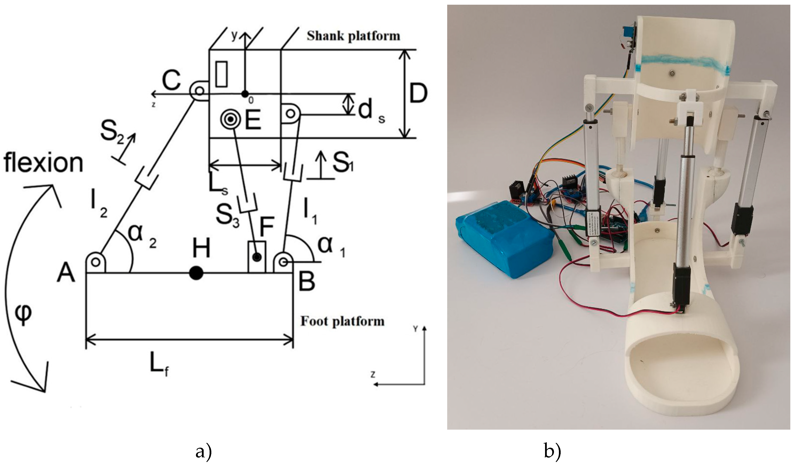
Figure 2.
Almaty Ankle Exoskeleton V.1 with the main components [24].
Figure 2.
Almaty Ankle Exoskeleton V.1 with the main components [24].
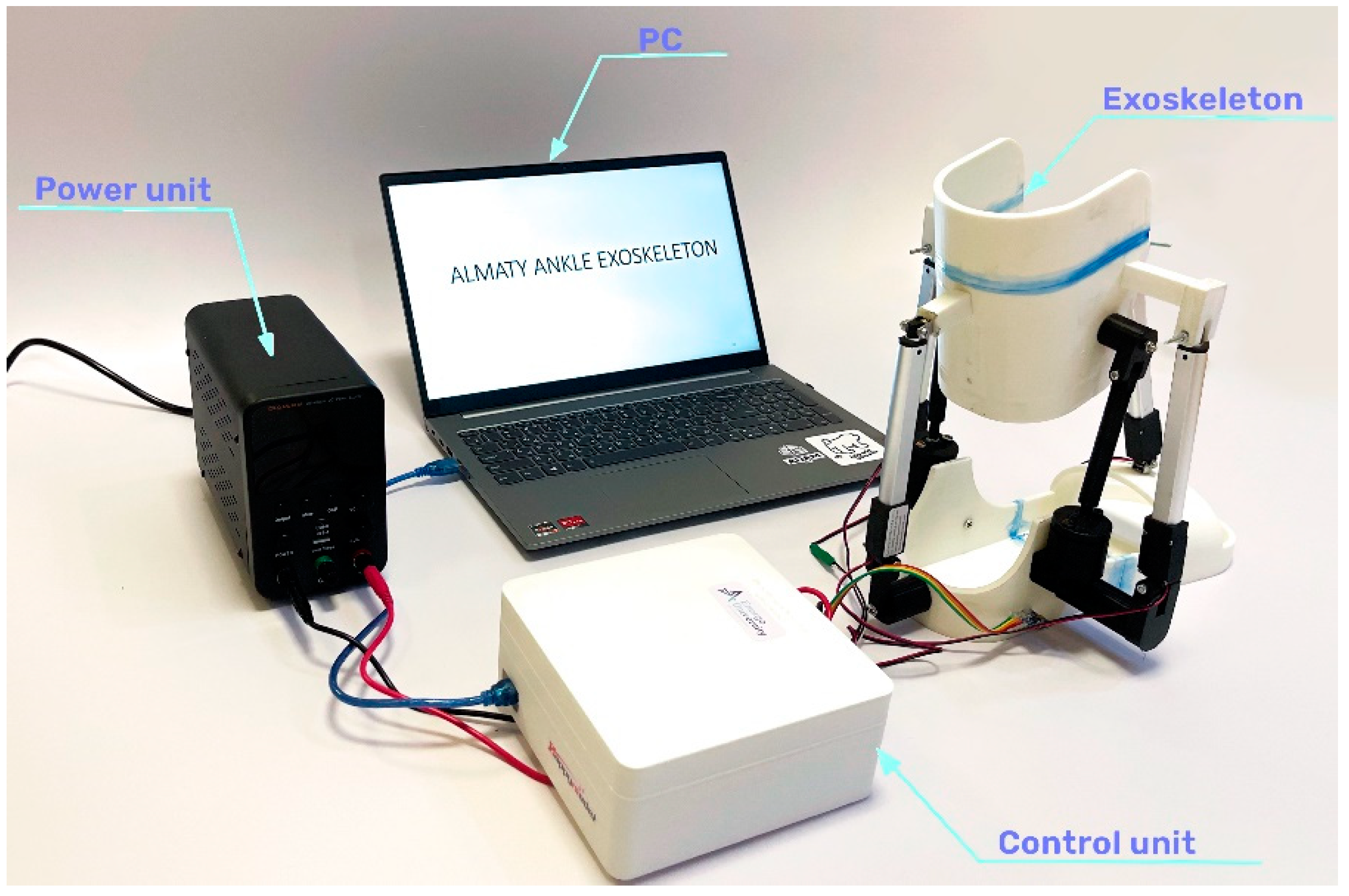
Figure 3.
Mechanical design of the prototype working on the leg.
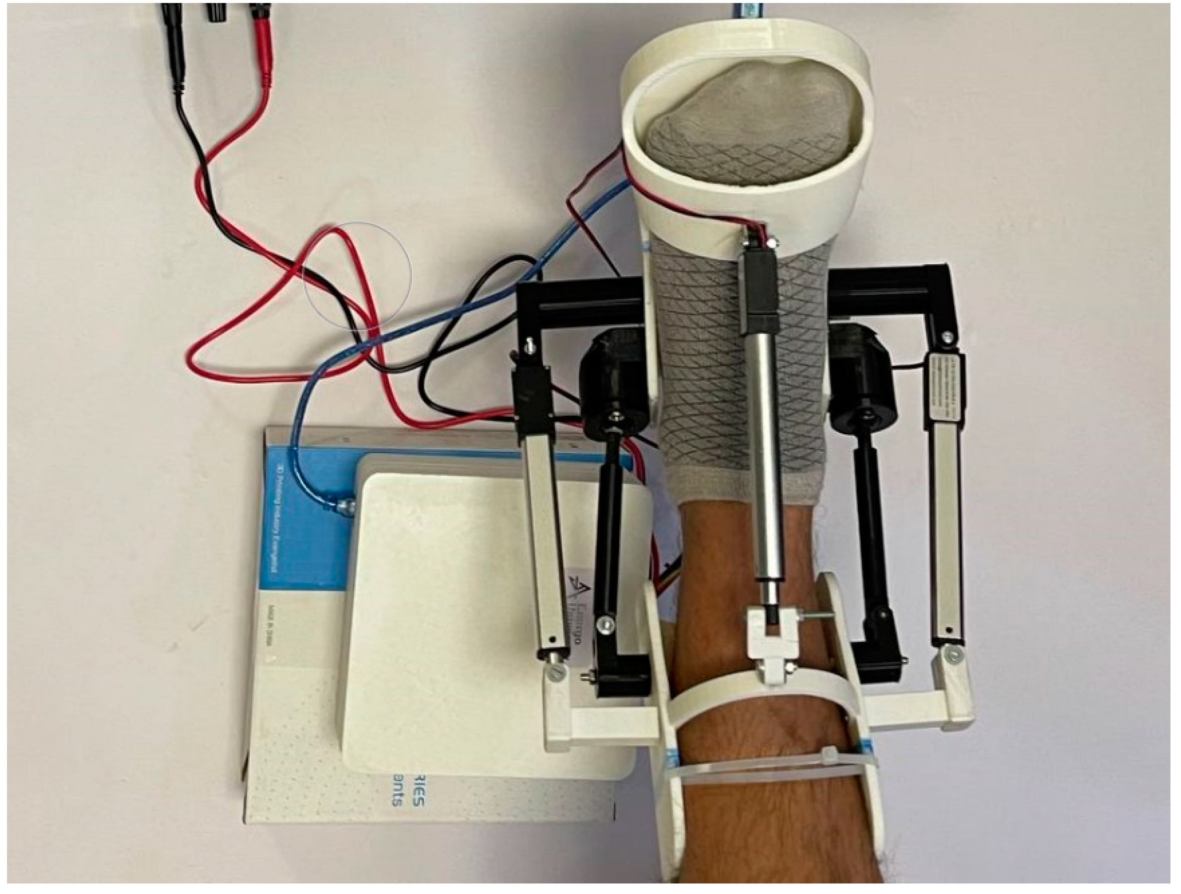
Figure 4.
A CAD design of the ankle motion- assisting exoskeleton: a) kinematic design; b) CAD model.
Figure 4.
A CAD design of the ankle motion- assisting exoskeleton: a) kinematic design; b) CAD model.
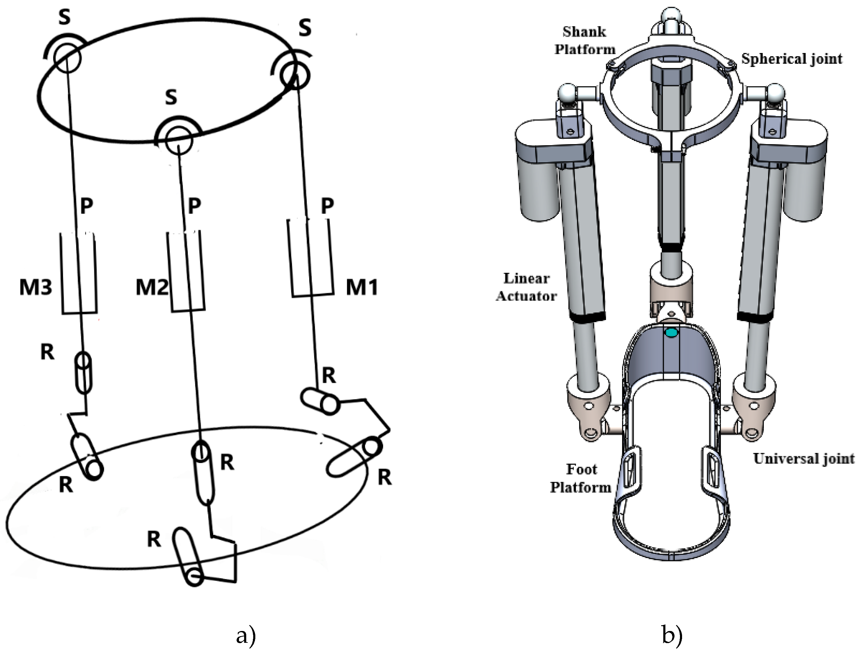
Figure 5.
The actuator that connects the Shank Platform and Foot Platform in Figure 4.
Figure 5.
The actuator that connects the Shank Platform and Foot Platform in Figure 4.
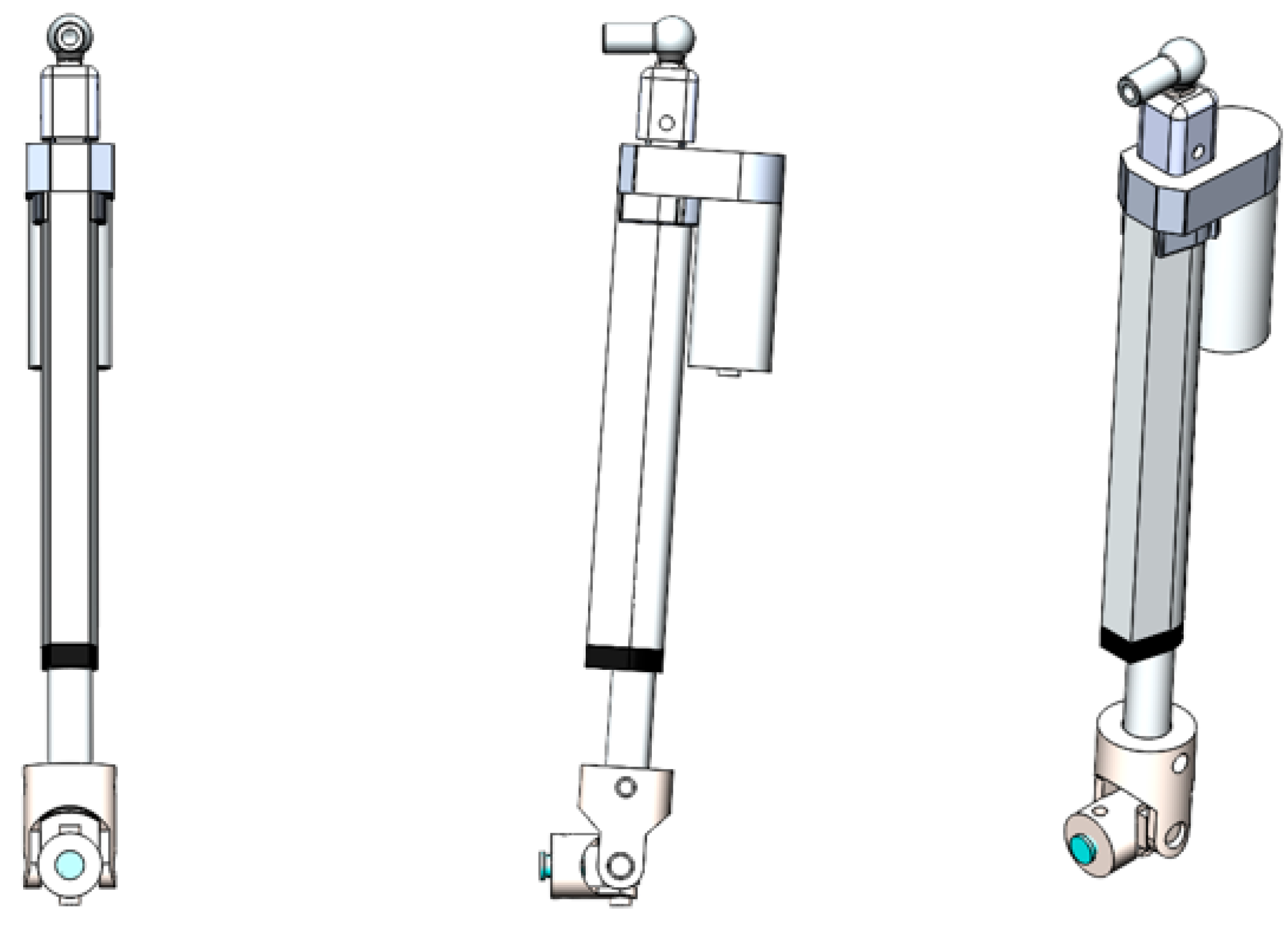
Figure 6.
Exploded view of CAD model of exoskeleton ankle in Figure 4 with structural elements. (1 - shank platform; 2, 11 - angle joints; 3, 5, 12 - linear electric actuator (S1, S2, S3); 4 - actuator attachment (S3); 6 - the internal circuit of the actuator; 7, 8, 13 - universal joint designed to connect the actuator to the platform; 9 - Foot platform; 10 - Shank platform fixture designed to fit the size; 14 - Foot platform attachment with ankle).
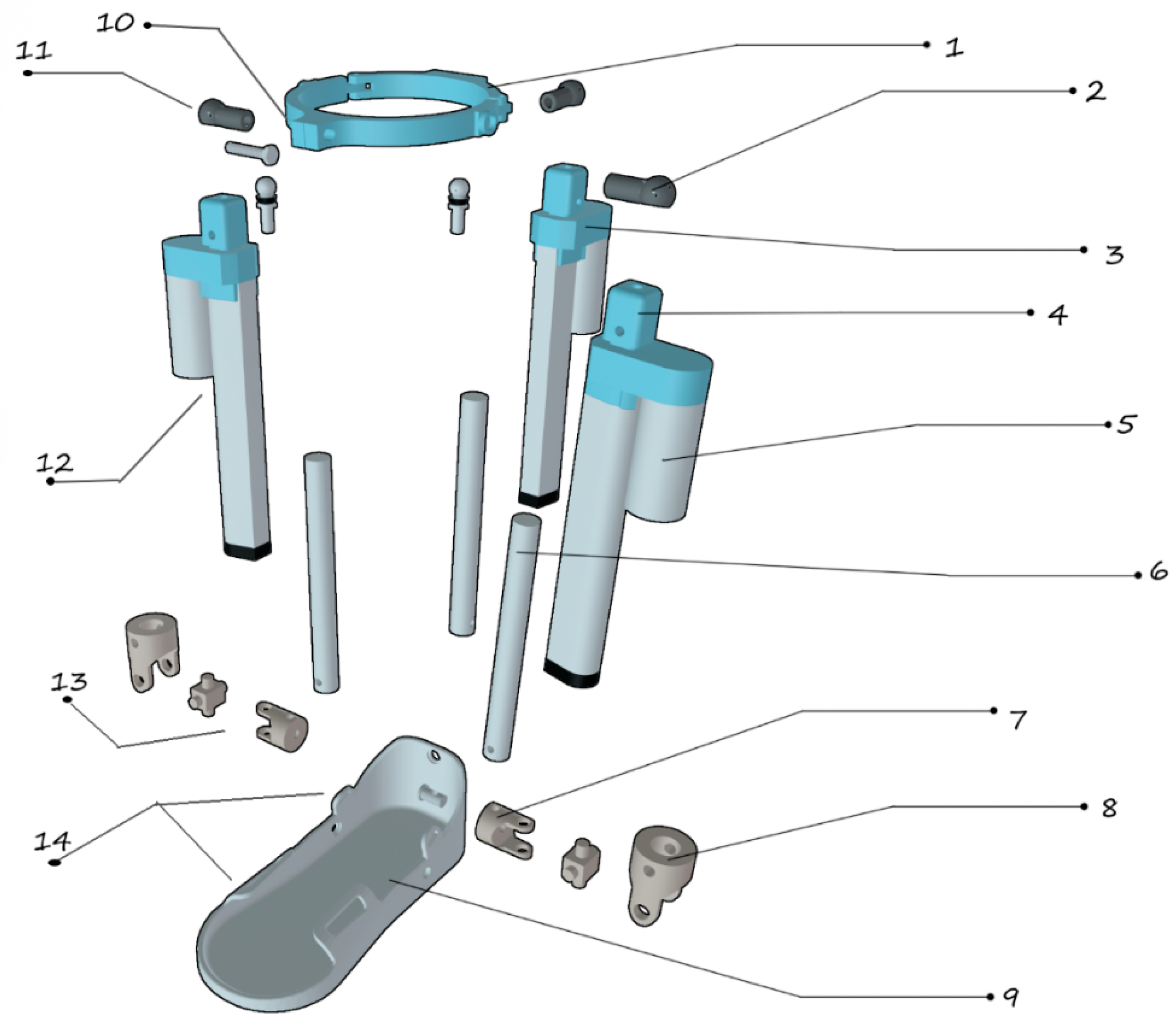
Figure 7.
Technical design of the proposed Almaty Ankle Exoskeleton V.2.
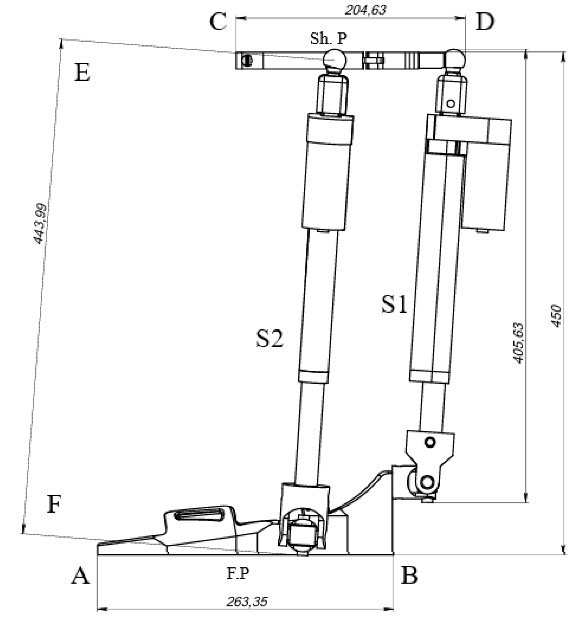
Figure 9.
Picture of assembled prototype: a) Foot ring b) Shank ring.
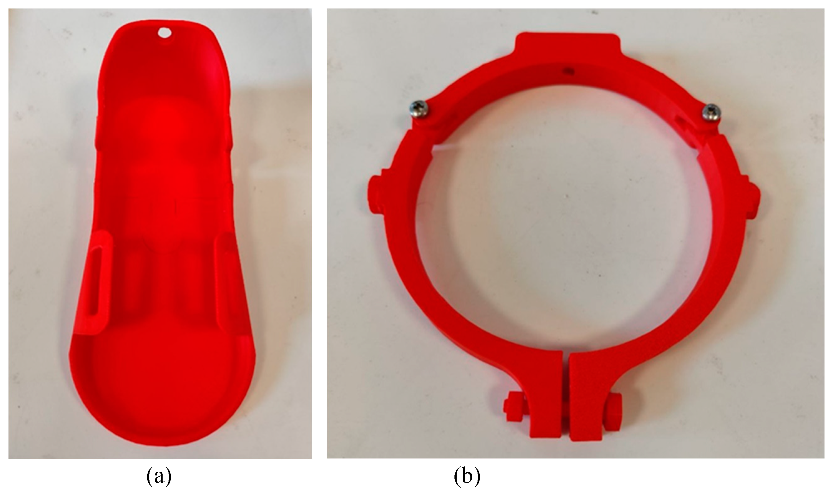
Figure 10.
Electric linear actuator with (a) universal joint connection (b) spherical joint connection.
Figure 10.
Electric linear actuator with (a) universal joint connection (b) spherical joint connection.
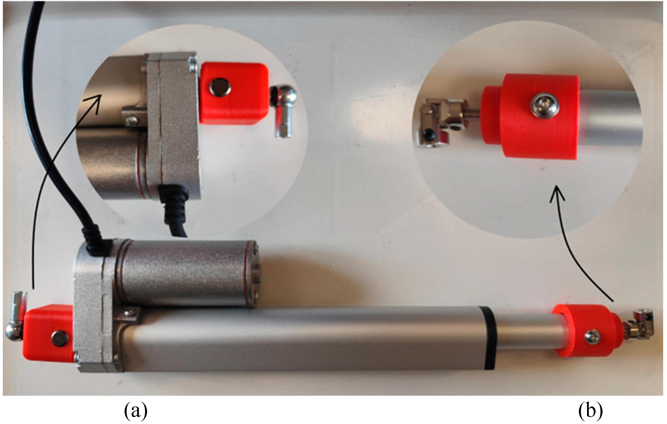
Figure 11.
Almaty Ankle Exoskeleton V.2 the full prototype.
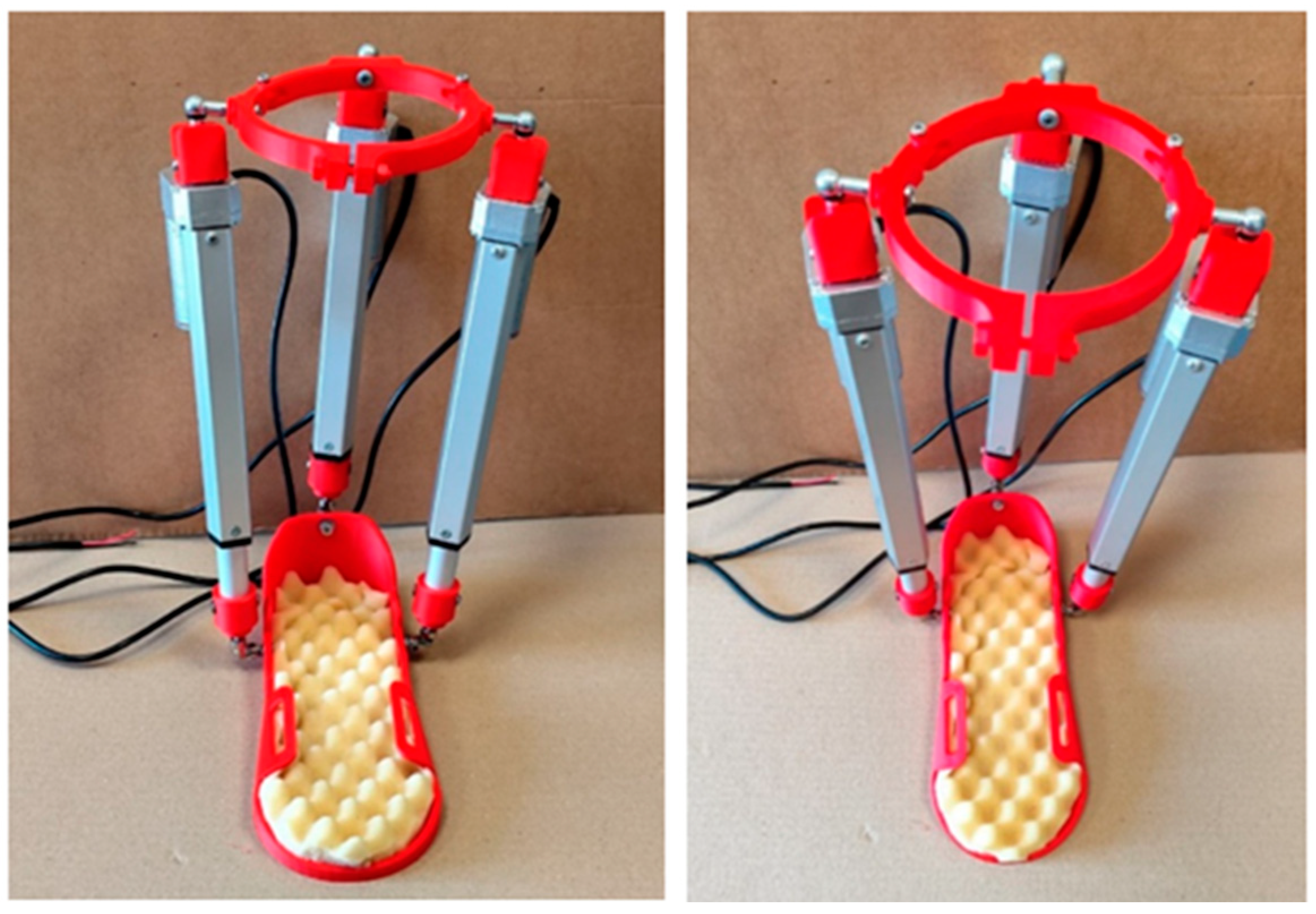
Figure 12.
The circuit design for a lab prototype.
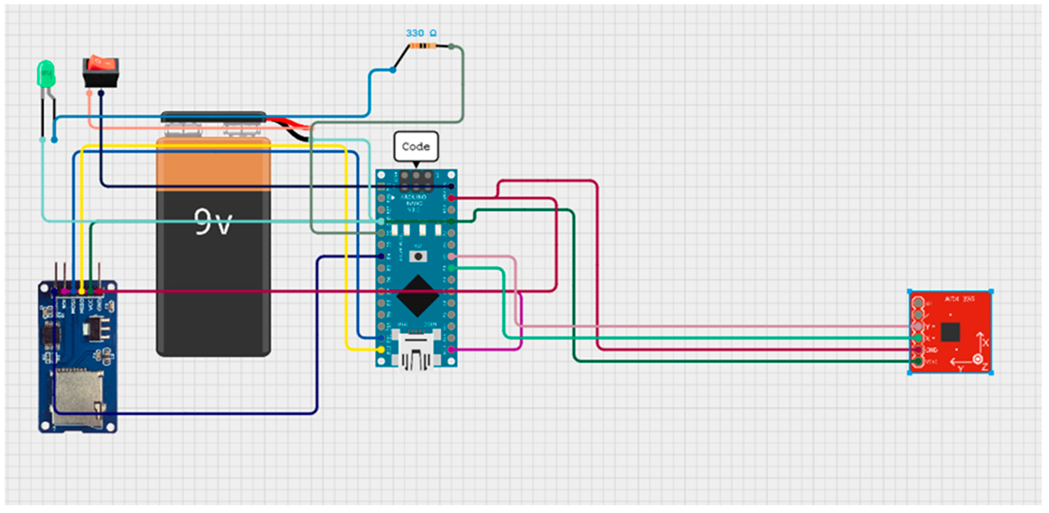
Figure 13.
A device for reading the movement of the ankle joint during rehabilitation.
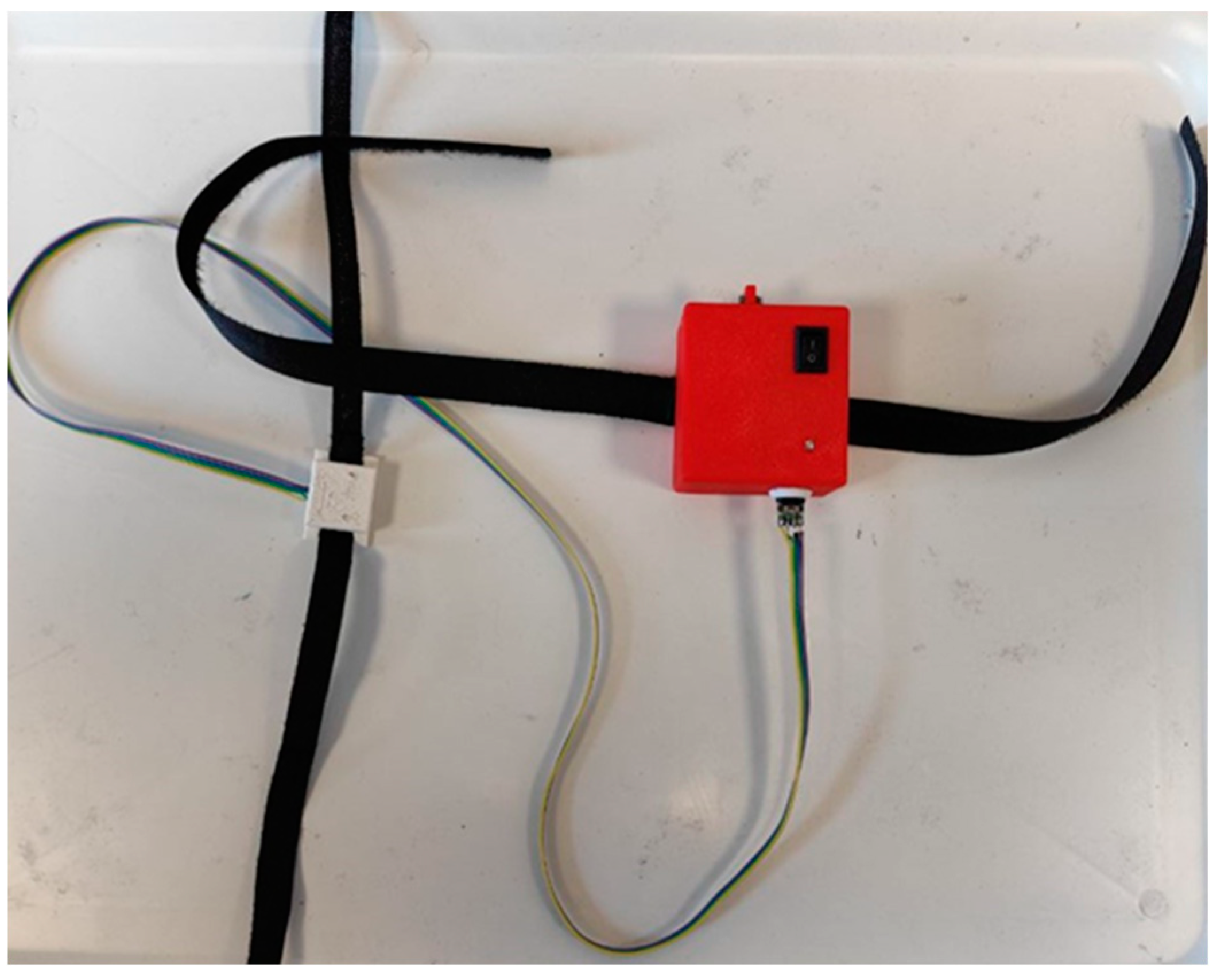
Figure 14.
Тesting models Almaty Ankle Exoskeleton V.2.
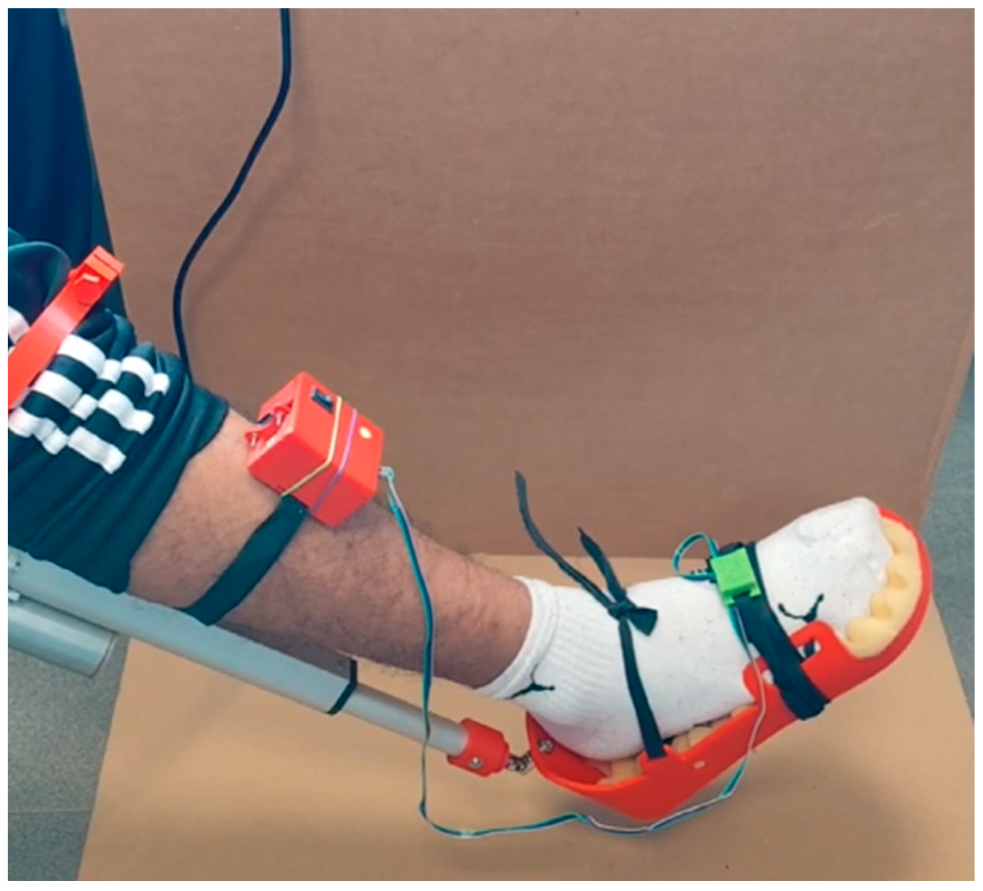
Figure 15.
Lab setup. (1- Linear Actuator; 2- Arduino Uno; 3- L298N motor driver; 4- 12V DC; 5- joystick).
Figure 15.
Lab setup. (1- Linear Actuator; 2- Arduino Uno; 3- L298N motor driver; 4- 12V DC; 5- joystick).
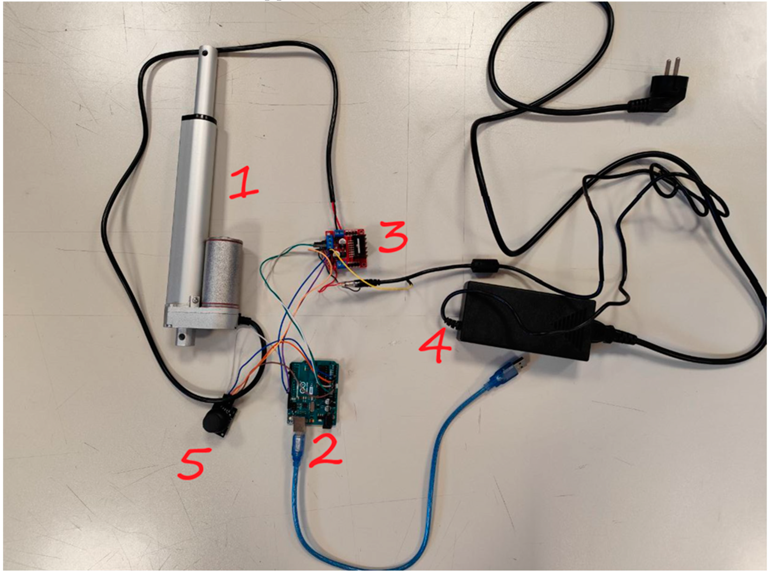
Figure 16.
Snapshot of a functional test of ankle joint movement dorsal and plantar flexion.
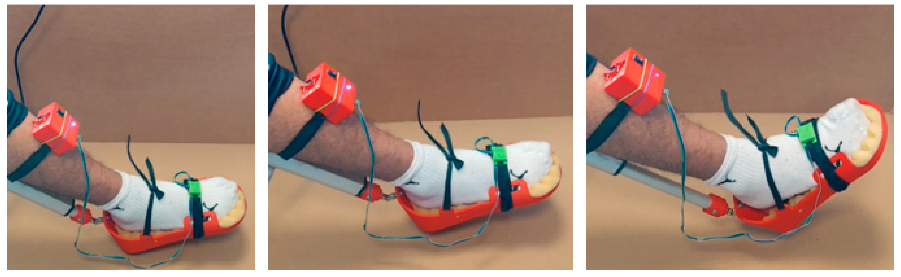
Figure 17.
The results of the laboratory test, presented in Figure 16, show the angular velocity measured by the IMU sensor.
Figure 17.
The results of the laboratory test, presented in Figure 16, show the angular velocity measured by the IMU sensor.
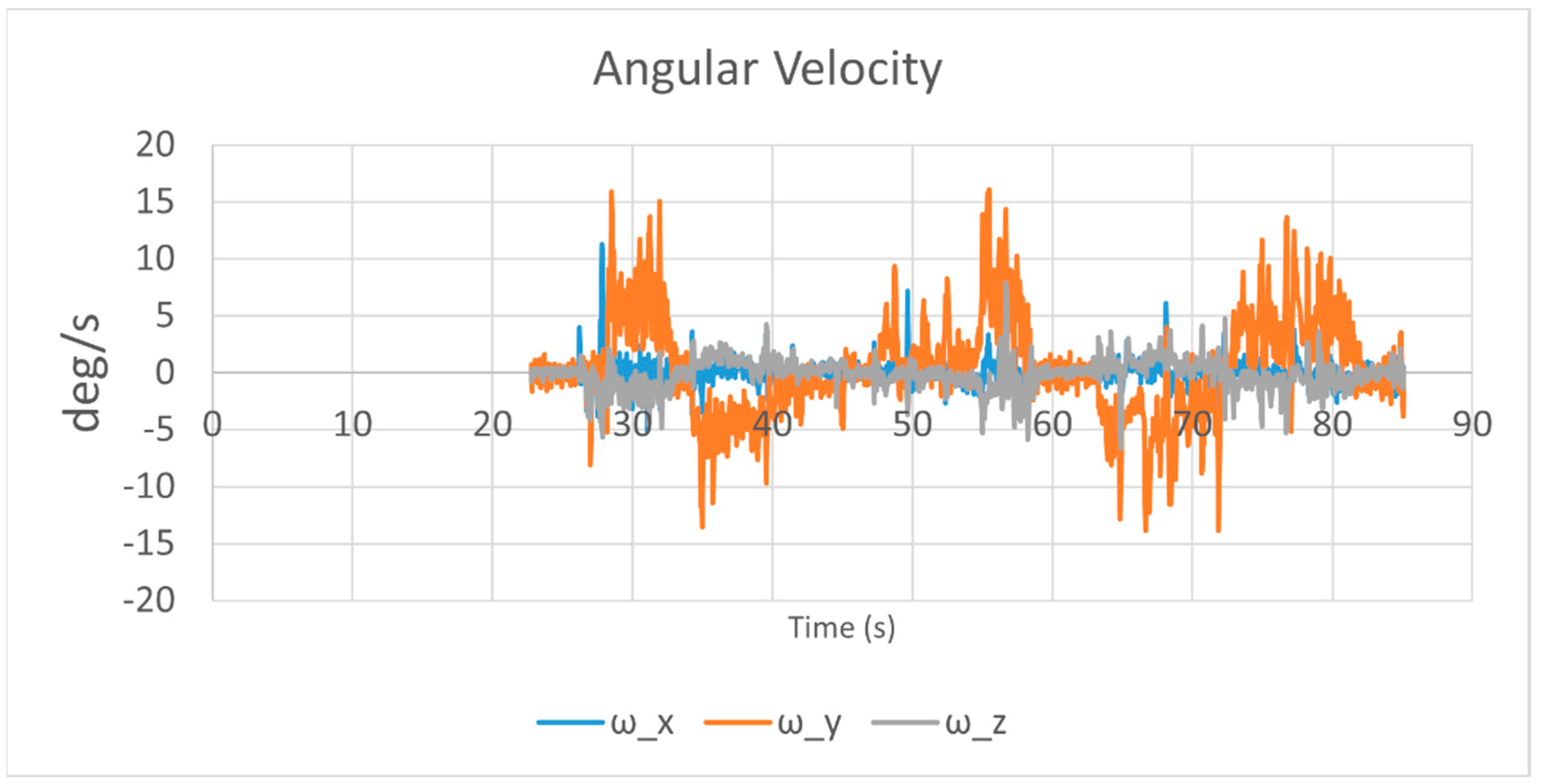
Figure 18.
Results of linear acceleration movement with dorsal and plantar flexion in Figure 16.
Figure 18.
Results of linear acceleration movement with dorsal and plantar flexion in Figure 16.
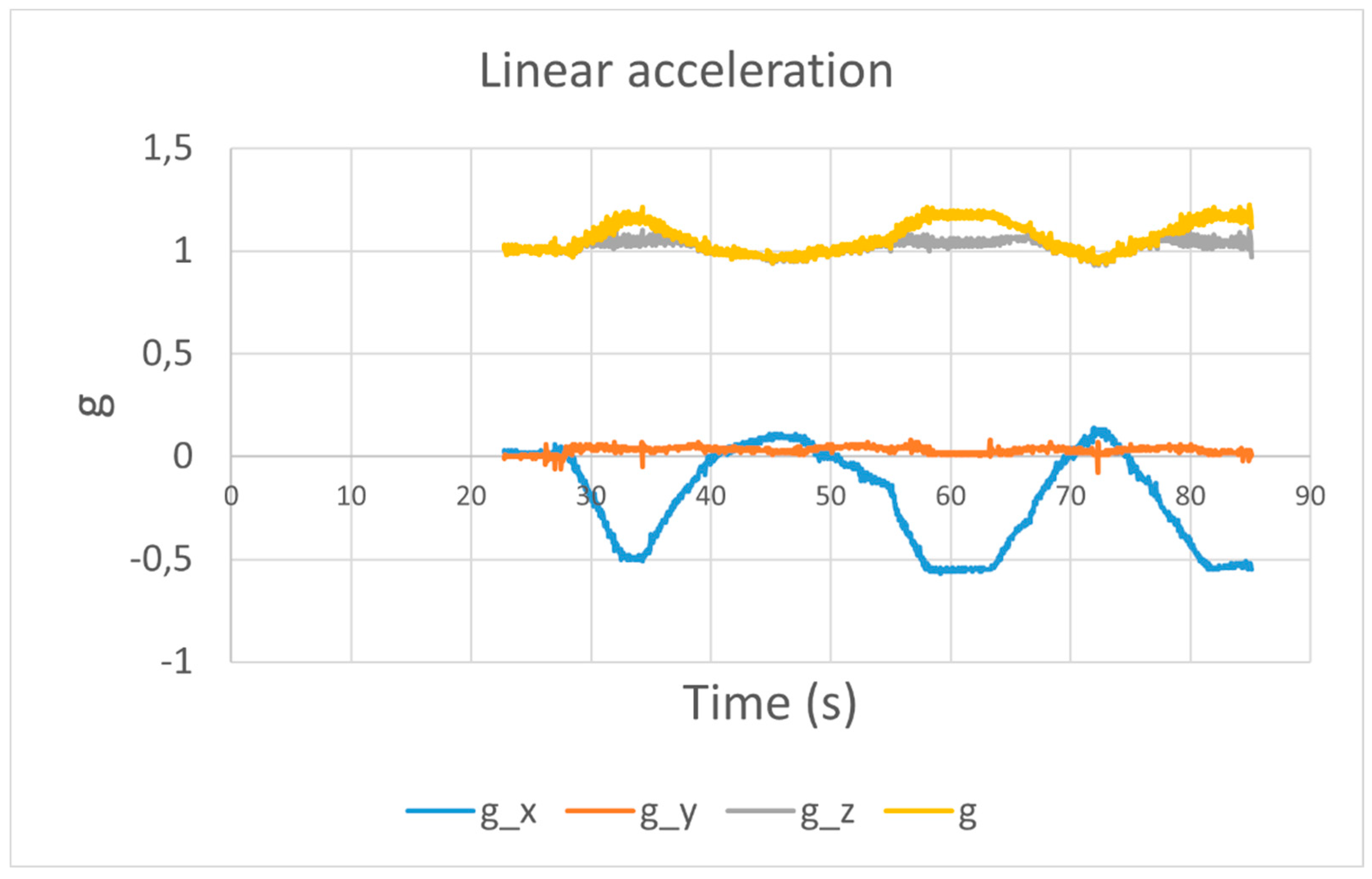
Figure 19.
Acquired results of test like in Figure 16 in terms plots of angles Pitch and Roll, Yaw in Figure 16.
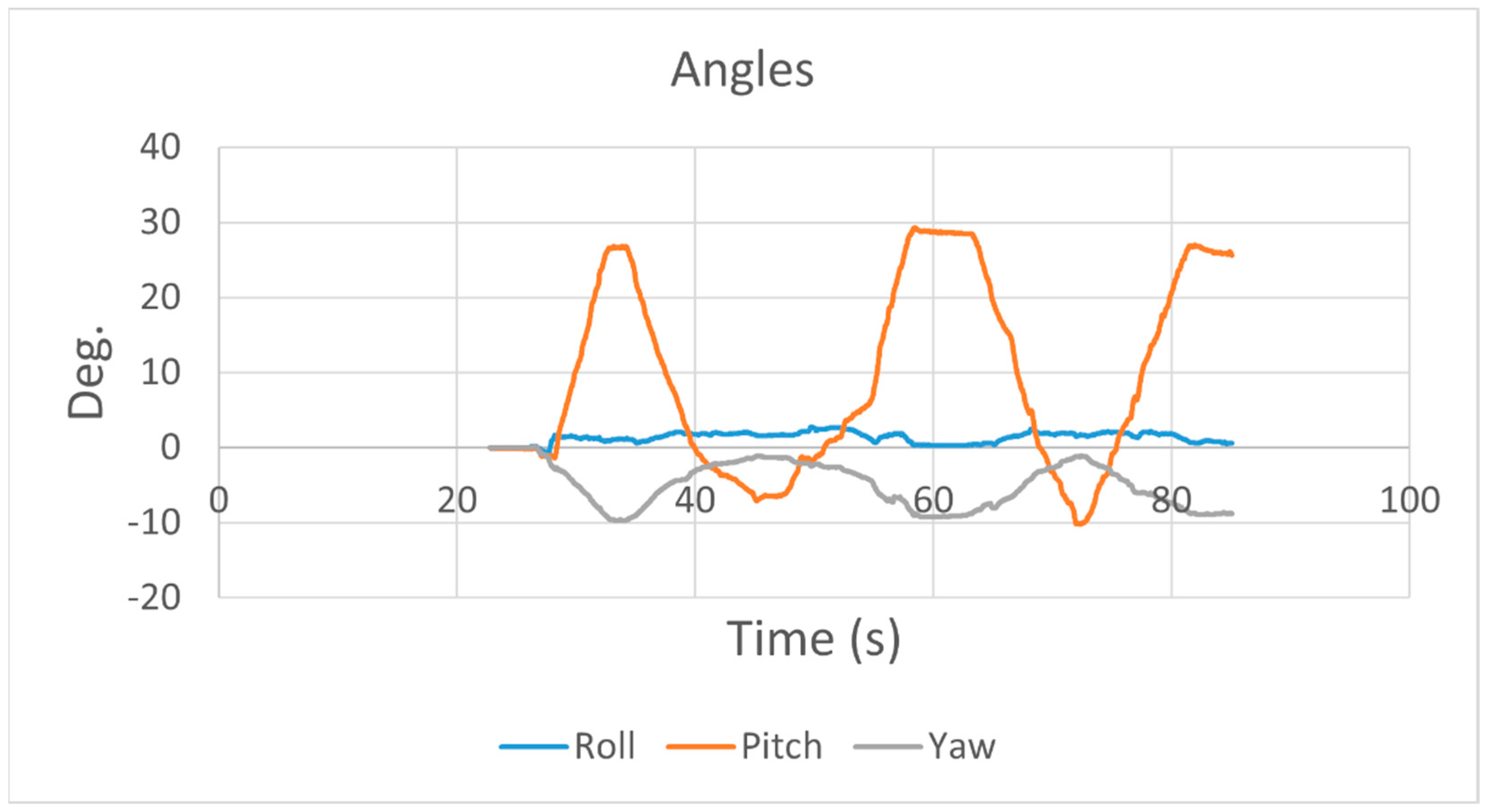
Figure 20.
Snapshot of a second functional test of ankle joint movement dorsal and plantar flexion.
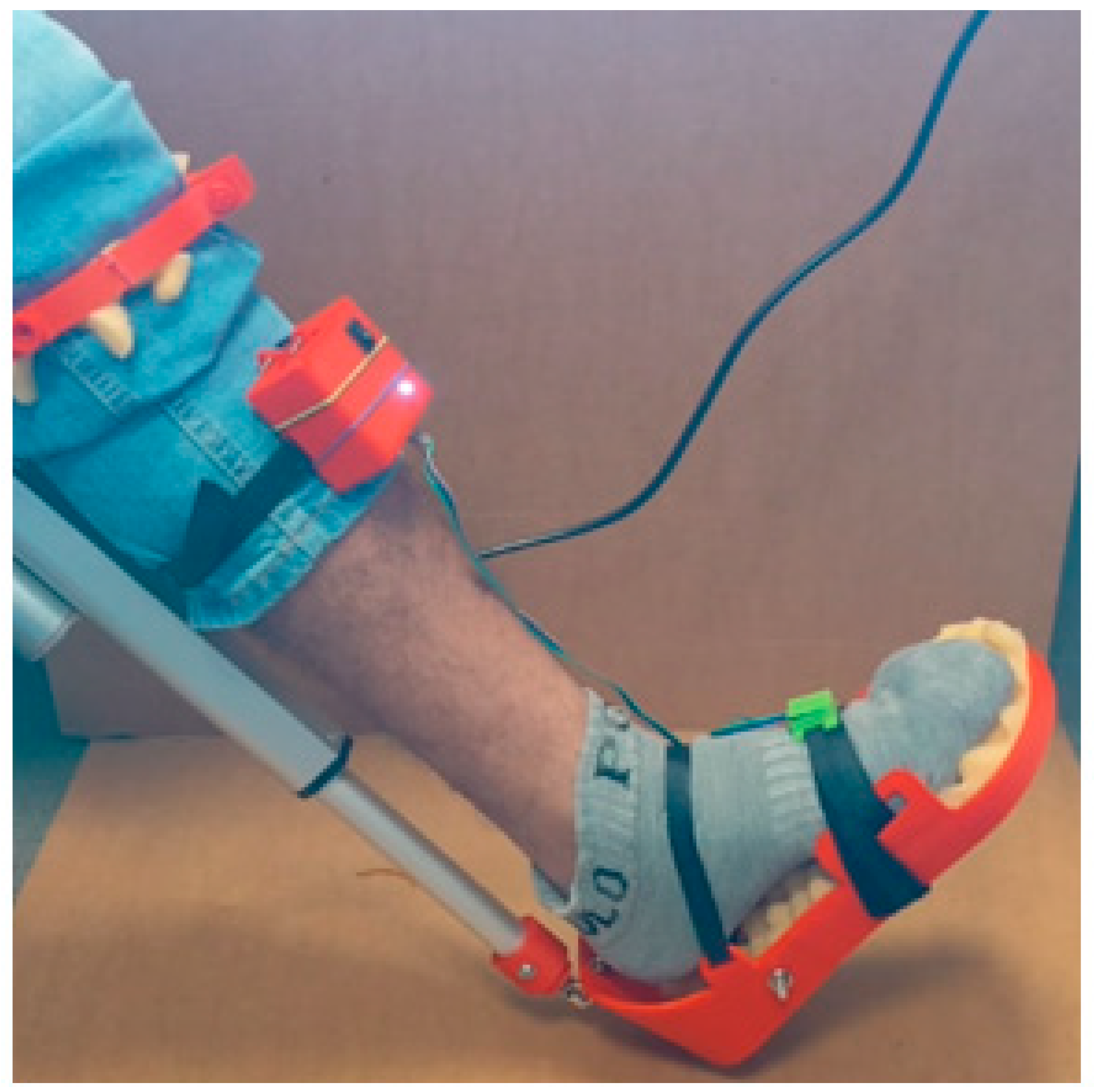
Figure 21.
The results of Investigations of the angular velocity of the ankle joint during dorsal and plantar flexion are presented.
Figure 21.
The results of Investigations of the angular velocity of the ankle joint during dorsal and plantar flexion are presented.
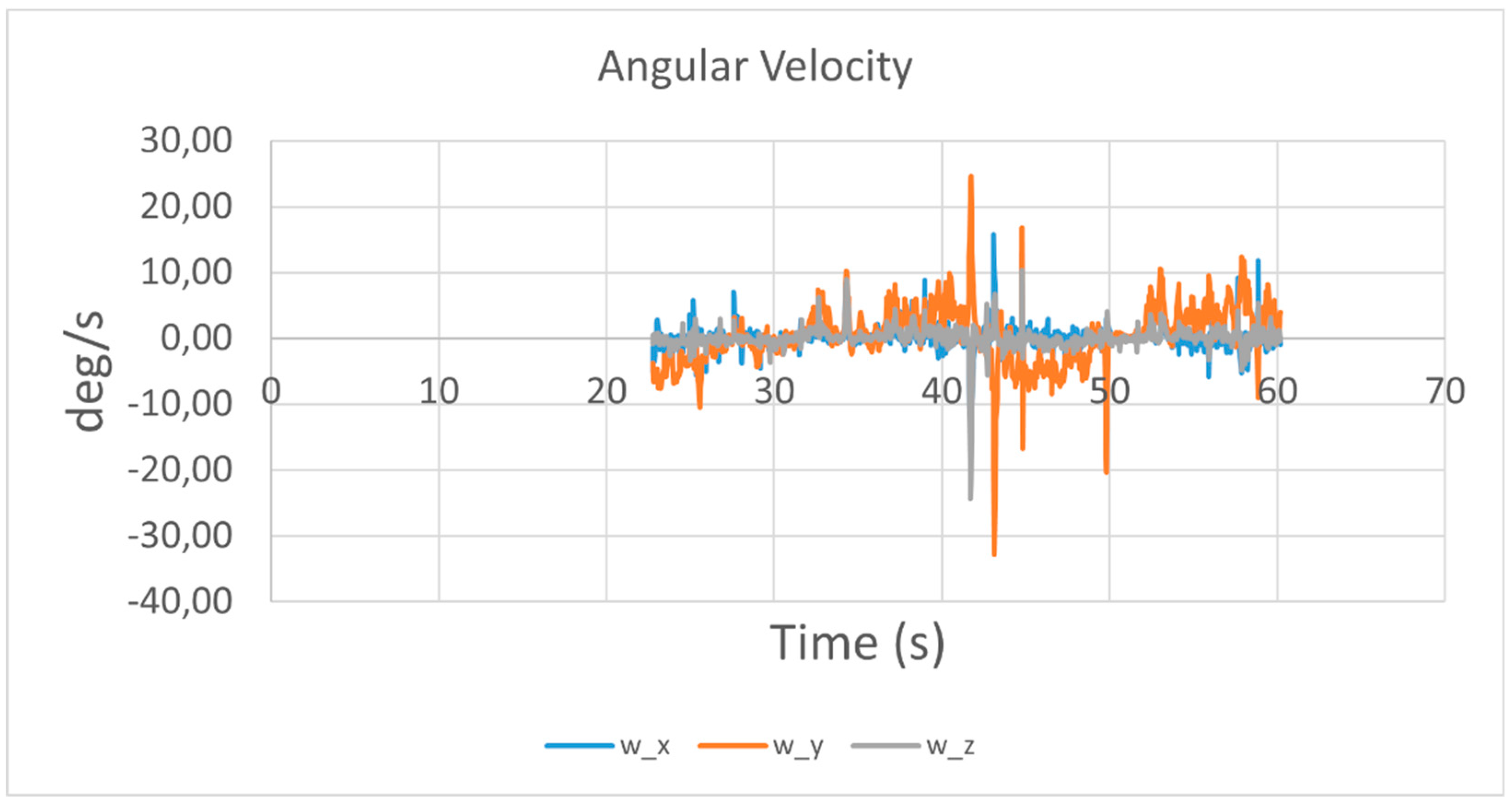
Figure 22.
Results of linear acceleration movement with dorsal and plantar flexion.
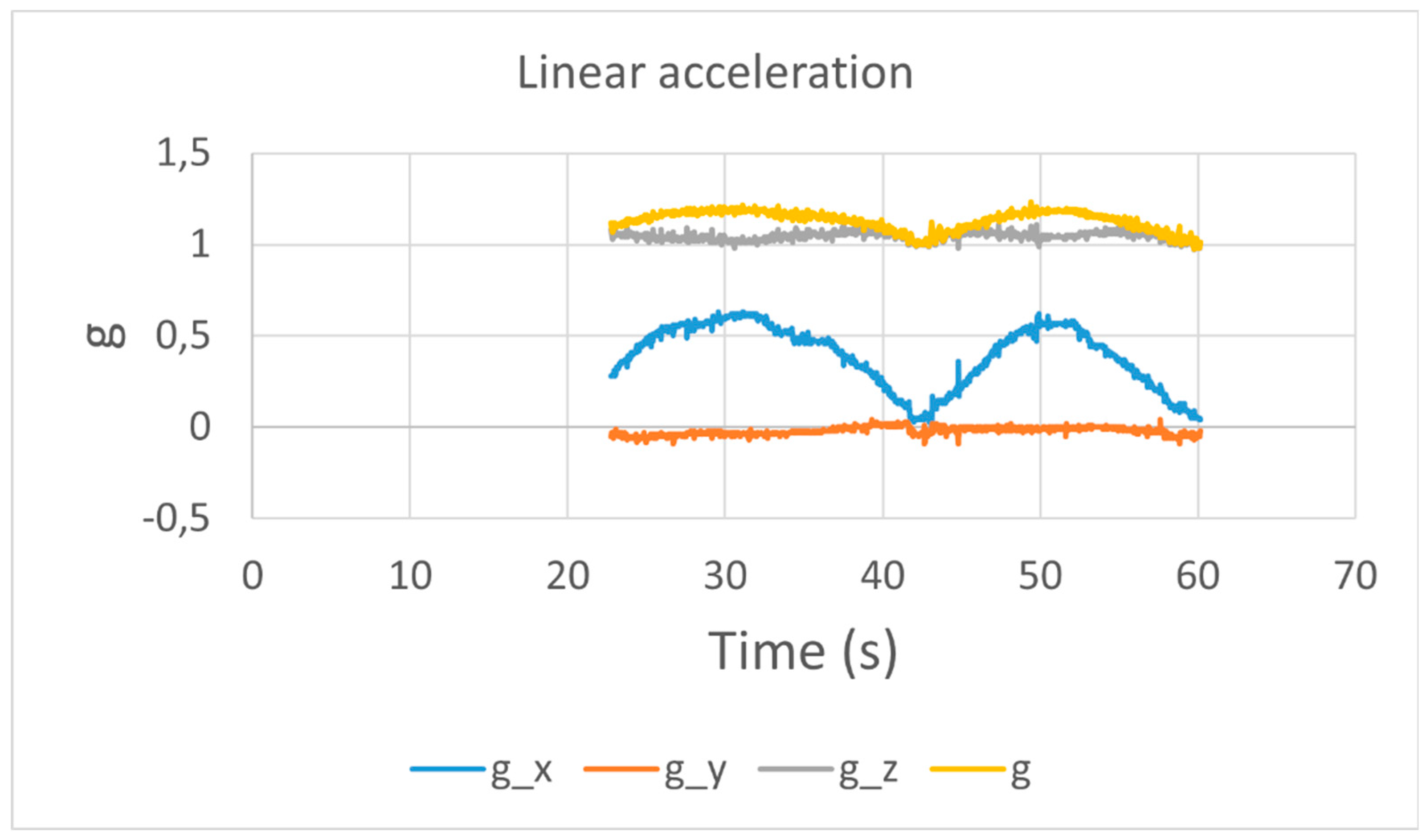
Figure 23.
Acquired results of test like in Figure 20 in terms plots of angles Pitch and Roll, Yaw.
Figure 23.
Acquired results of test like in Figure 20 in terms plots of angles Pitch and Roll, Yaw.
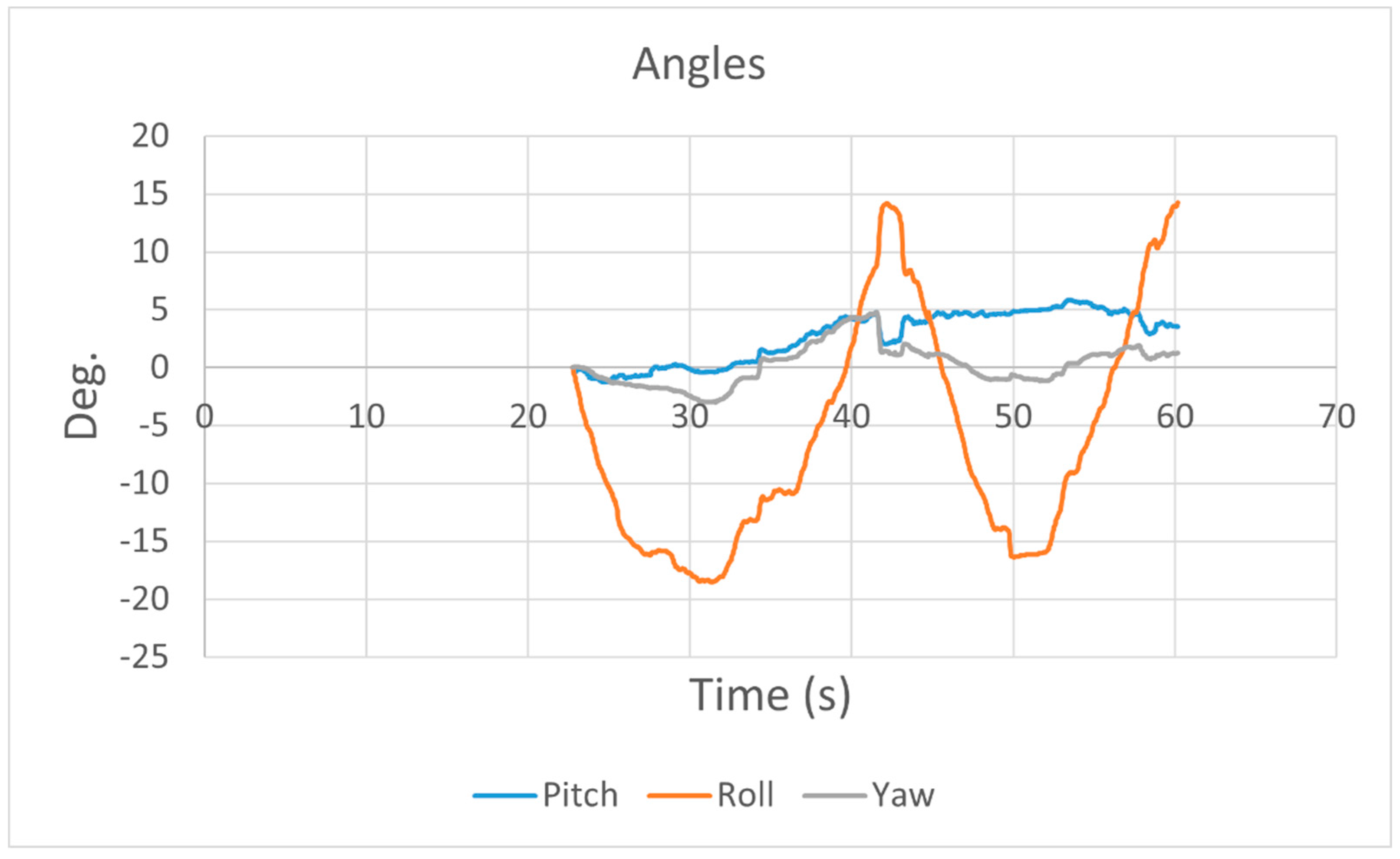

Table 1.
Design and operation parameters of mechanical design in Figure 7.
Table 1.
Design and operation parameters of mechanical design in Figure 7.
| Size (mm) | Sh.P | F.P | S1 | S2 | S3 | DB |
| 204,63 | 263,35 | 405,63 | 443,99 | 443,99 | 450 |
Table 2.
Summary of the test results data obtained, indicating the functional test of the ankle dorsiflexion exoskeleton- plantarflexion.
Table 2.
Summary of the test results data obtained, indicating the functional test of the ankle dorsiflexion exoskeleton- plantarflexion.
| Parameters | Angular Velocity | Linear Acceleration | Angles |
| 1 Test | -15 to 15 deg. | -1 to 1.5 m/s². | -15 to 35 deg. |
| 2 Test | -20 to 20 deg. | 1 to 1.5 m/s² | 15 to -20 deg. |
Disclaimer/Publisher’s Note: The statements, opinions and data contained in all publications are solely those of the individual author(s) and contributor(s) and not of MDPI and/or the editor(s). MDPI and/or the editor(s) disclaim responsibility for any injury to people or property resulting from any ideas, methods, instructions or products referred to in the content. |
© 2024 by the authors. Licensee MDPI, Basel, Switzerland. This article is an open access article distributed under the terms and conditions of the Creative Commons Attribution (CC BY) license (http://creativecommons.org/licenses/by/4.0/).
Copyright: This open access article is published under a Creative Commons CC BY 4.0 license, which permit the free download, distribution, and reuse, provided that the author and preprint are cited in any reuse.


