
Submitted:
12 August 2024
Posted:
13 August 2024
You are already at the latest version
Abstract
This paper presents a study on developing of a new exoskeleton for ankle joint rehabilitation with three degrees of freedom (3 DOFs). The primary attention is paid to the process of designing and modelling the device aimed at restoring the lost functions of joint mobility. The authors carried out a complex analysis of the functional requirements of the exoskeleton based on the research of potential user’s needs, which allowed them to develop a conceptual model of the proposed de-vice. In this study, a prototype of the exoskeleton is designed using modern additive technolo-gies. A prototype of the proposed device underwent virtual testing in conditions maximally close to the real one, which confirmed its effectiveness and comfort of use. The main results of the work indicate the promising potential of the proposed solution for application in rehabilitation practice, especially for patients with ankle joint injuries and diseases.
Keywords:
ankle exoskeleton
; motion assisting devices.
; design and simulation
; biomechanics
1. Introduction
The musculoskeletal apparatus includes bones, joints, ligaments, muscles and their nerve formations. The entire combination forms a single system, which together provides mechanical protection for the internal organs of a person and also performs support tasks, providing the ability to move. Any disruption or damage to any part of this system can have serious negative consequences. These include more than 150 different types of diseases and conditions, such as injuries to bones, fractures, and joints, including sprains or tears of ligaments and muscles, including damage to nerve bundles, resulting in temporary or lifelong limitations in function and movement in everyday life [1]. In this case, rehabilitation and medical care Are instrumental in restoring musculoskeletal function after injuries and chronic diseases. These measures help to regain and improve the ability to move and maintain the person's overall quality of life.
Rehabilitation, as an essential health service, plays a crucial role in achieving universal health coverage in any country. According to the World Health Organization, about 2.4 billion people worldwide are currently living with health problems that can be improved through rehabilitation [2]. Of these, about 1.71 billion people suffer from musculoskeletal disorders, among which 86 million people need rehabilitation process in the aftermath of a stroke. Given the changes occurring in the health status and characteristics of the population worldwide, the estimated need for rehabilitation will only increase in the coming years [3], which emphasizes the importance of research in the development and implementation of the latest rehabilitation technologies and techniques to improve the quality of life and health of the population.
One of the key areas of development in this field is the creation of a wide range of devices used in medical practice in rehabilitation, from simple instruments to complex life support systems and surgical robots. These innovations help to combat various musculoskeletal conditions, which ultimately improves diagnosis and treatment processes, as well as speeding up the recovery process, which facilitates more efficient interaction between patients and doctors.
The impact of such devices on improving the quality of life and health of the population is invaluable. They are widely used in various fields of medicine and health care, such as orthopaedics and traumatology, neurology and neurorehabilitation, physiotherapy and sports medicine, as well as cardiology and respiratory therapy. These devices have many advantages. They help to accelerate the recovery process, improve the functional capabilities of the body, reduce the risk of complications after illness or injury, and increase patients' motivation for rehabilitation [4]. In addition, these devices allow the development of individualized recovery programs tailored to the characteristics and needs of each specific patient. This contributes to the best results and effective treatment, helping patients to return to a full life and become more independent and active in their daily activities.
Despite these advantages, the rehabilitation of the musculoskeletal system currently faces many challenges due to the cost of development technology, lack of resources, including the lack of assistive technology, equipment and devices, including consumables, as well as the need for additional research and data collection on the rehabilitation process [5]. Given the importance and significance of the rehabilitation process in patients today, in most cases, the rehabilitation process is realized mainly manually by physicians. This approach faces problems such as high labour intensity, dependence on physician experience, difficulty in accurately controlling exercise parameters and evaluating the effects of rehabilitation, which raises the urgency of research in the creation of accessible modern technologies and atomized rehabilitation systems and devices that provide more accurate control of exercise parameters and allow the collection of data on their effectiveness, which can lead to more personalized treatment plans.
Introducing such innovations into rehabilitation requires a comprehensive approach, including training specialists, integrating new technologies into clinical practice, and continuously monitoring results. This will ultimately reduce the risk of errors and increase patients' motivation to return to a whole life quickly. This process can be an essential step towards more effective and affordable rehabilitation methods and offer patients increasingly effective and convenient solutions.
The development and production of rehabilitation devices is a complex and multi-stage process involving many aspects, starting with research, design and prototype development, followed by virtual and practical testing to identify possible problems and deficiencies. Compliance with all standards and regulations set in the medical device field is also an essential part of the process. In addition, it is necessary to consider the specifics of using the device for medical purposes, such as the possibility of prolonged contact with the human body, to maximize the safety and reliability of the device [6]. Among such devices, robotic exoskeletons have been widely used to help patients after strokes, brain injuries, spinal cord injuries, and for patients with muscle or joint diseases. They are also effective in rehabilitating patients with various ankle injuries. These devices aim to improve movement coordination, strengthen muscles, increase joint mobility and improve balance. [7].
Due to the high activity of daily life, the ankle joint becomes one of the most vulnerable joints of the human musculoskeletal system, which is characterized by a complex structure, significant load and flexibility of movement, playing an integral role in daily life. In addition, diseases such as stroke and spinal cord injuries can cause muscle weakness, spasticity, poor control of ankle joint movements or even deformity [8], which displays the significance of research in the field of creating devices for human lower extremity rehabilitation.
Today, researchers worldwide are developing various types of rehabilitation devices using a wide range of methods and solutions, which raises the demand for creating new, innovative and affordable types of rehabilitation devices. Exoskeletons are emerging as an innovative lower limb solution to improve function in people with lower limb injuries. These devices are vital in restoring lost function after musculoskeletal diseases and injuries. Therefore, this research paper discusses the development of a new exoskeleton for ankle rehabilitation from a design and modelling perspective. This development will be capable of restoring the lost mobility functions of the ankle joint. The process of creating accessible exoskeletons for ankle rehabilitation represents a significant step forward in biomedical engineering and involves several key aspects, as reviewed by the authors in this research. In the first phase of the research to determine the basic functional requirements for an exoskeleton, the research first conducted a thorough investigation of the needs of potential users, including an analysis of their lifestyle, types of ankle injuries and diseases, and the impact of such devices on the current health status of the rehabilitated patient in a human-machine interaction environment. The next stage involves conceptual design, where the initial concept of the exoskeleton is developed. This includes selecting key components such as power transmission mechanisms, control systems, and sensors to monitor joint position and load. It is also important to consider the device's aesthetics and usability during rehabilitation. The final stage involves developing and virtual testing an ankle exoskeleton prototype. The prototype is developed and tested virtually in conditions as close to real life as possible to assess its effectiveness, reliability, and comfort of use. By realizing all the above stages, the study's authors created an accessible, inexpensive exoskeleton prototype with three degrees of freedom, which will become an effective means of rehabilitation for patients with various injuries and traumas of the ankle joint. Widespread use of such devices in clinical practice opens vast opportunities for restoring patient motor function. They allow for improvement in the quality of life of rehabilitated patients, increasing the level of independence and mobility and making the rehabilitation process more effective and personalized.
The main feature of the proposed rehabilitation exoskeleton is the presence of three degrees of freedom, which allows the effective control of the movement of the ankle joint in all its possible states. This allows the device to mimic the natural movements of the ankle joint, creating a smoother and more natural walking experience for the patient, which speeds up the rehabilitation process. Such an exoskeleton may be helpful to patients in chronic disease management processes and rehabilitation processes following ankle injuries such as fractures or ligament changes. This perspective device can be applied to support people with difficulty walking due to age-related changes in their bindings.
2. Related Work
The inability to walk due to conditions such as stroke, musculoskeletal disorders, and spinal cord injuries is a serious problem today. In many cases, injuries of this nature cause loss of motor function in the lower extremities, encompassing the hip, knee, ankle, foot, or a combination of these. In such situations, restoring lost or limited mobility of the lower limbs using robotic rehabilitation significantly improves the patient's quality of life, allowing people to become independent and active again [9,10]. Over the last decade, robotic rehabilitation of the lower limbs has significantly improved. Today, it is a high-tech solution that helps to restore the motor and functional capabilities of patients with movement disorders. In this case, the effectiveness of these solutions is assessed by a comprehensive approach and close interaction between the rehabilitation device, patient, physician, physiotherapist and other specialists. More affordable and effective ways to improve rehabilitation are using robotic exoskeletons to restore lower limb function [11]. In this direction, researchers worldwide are developing new technologies to improve human lifestyles using different approaches and development methods. Many modern types and kinds of rehabilitation exoskeletons have been developed, and mechanisms, control systems, sensors, etc., have been improved. All the studies can be a good background for developing a new rehabilitation robotic exoskeleton, which is presented in this work.
Many studies in the field of musculoskeletal rehabilitation devices have focused on the development and testing of exoskeletons to restore ankle joint function. Much of the research and development has focused on the rehabilitation of patients after stroke, as stroke can lead to severe motor impairment and loss of function, and in the worst case, death [12]. The consequences of stroke can lead to partial or total disability, which affects a person's muscle strength and functional mobility in general. In countries around the world, stroke remains a common public health problem and remains the second leading cause of human mortality, with an annual incidence of about 180 cases per 100,000 people [13]. According to the source [14], after stroke, one-third of survivors live longer than three months, and a significant proportion of ambulatory patients lose upper and lower limb mobility functions. Subsequently, they must use wheelchairs and other assistive devices, experiencing a marked decrease in walking speed and endurance. Consequently, restoring and optimizing ambulatory function in stroke is of paramount importance to facilitate social and vocational reintegration. Among stroke patients, the introduction of exoskeleton technology is promising, given the increasing prevalence of stroke and associated mortality rates. In this direction, the authors of the study [15] emphasize the importance of taking into account the evaluation of biomechanical ef- fects to improve rehabilitation efficiency and patient comfort. Experiments were conducted using AGoRA and T-FLEX exoskeletons (WE&T). The results of the study show a significant reduction in muscle activity by 50% in the biceps femoris, 59% in the lateral calf muscle and 35% in the tibialis anterior muscle when using the T-FLEX and AGoRA exoskeletons together. The use of this development in clinical practice can significantly reduce muscle activity without changing gait or stability parameters but cannot significantly affect the change in overall gait. The authors [16] demonstrated a prototype with a five-link mechanical system having two degrees of freedom (2DOF). The key innovation is the anthropomorphic structure of the exoskeleton. It includes a variable instantaneous center of rotation (ICR) that has the ability to adapt to the individual knee joint variability. But angular coordination of exoskeleton movements can be disturbed due to inconsistent synchronization of movements, which requires additional re-adjustment.
Other applications of rehabilitation exoskeletons have been studied by authors from different countries, among them the use as an aid for people with spinal cord injuries (SCI) characterized by paralysis [17,18]. According to global estimates by the World Health Organization, about 15 million people are living with spinal cord injuries worldwide today. Without effective prevention, treatment and rehabilitation can progress to severe and even life-threatening secondary conditions that lead to premature death of the individual [19]. Interventions in the acute phase prioritize non-emergency medical care, while the chronic phase entails persistent complications that require long-term rehabilitation and nursing support. More to the point, spinal cord injuries (SCI) often result in paralysis of the lower extremities, leading to complete loss of motor function in the lower extremities. In such situations, the application of exoskeletons in spinal cord injury rehabilitation shows significant potential and is becoming increasingly in demand due to its unique advantages. In this direction, the authors [20,21,22] discuss current trends in exoskeleton design and their integration with modern technologies such as artificial intelligence (AI), augmented (AR) and virtual reality (VR), and the Internet of Things (IoT). The listed studies emphasize the importance of developing lightweight, flexible and intelligent exoskeletons capable of integrating into everyday activities, which is relevant today. Despite the generalization of the listed studies, the authors did not fully consider the specific needs and physiological features of each case of exoskeleton application in the rehabilitation of spinal cord injury.
High biomechanical stresses in the workplace can also lead to a high risk of occupational musculoskeletal disorders. This creates the need for various assistive devices. Today, the scope of rehabilitation exoskeletons is expanding, and they are also being used in industry to reduce the strain on workers and provide prevention of various types of injuries. They can provide additional energy for human movement, which can be used in multiple fields, such as military, industrial and medical rehabilitation [23]. In this direction, the authors of the study [24,25,26,27,28] have developed industrial and vocational exoskeleton robots that provide physical assistance to workers in industrial facilities, enhanced by the use of various bio-signal measurement sensors and artificial intelligence.
Rehabilitation exoskeletons also play a vital role in the recovery process from various joint injuries by providing additional support and mobility, which helps prevent further deterioration of the joints and ligaments of the musculoskeletal system. Compared to other parts of the lower extremities, the ankle joint is subjected to significant stresses and strains, which makes it particularly vulnerable to various types of injuries, such as sprains and fractures [28]. In addition, the authors of the study [29] believe that it is the most commonly injured joint in more than 70 sports, including aerobic exercise, rock climbing, indoor volleyball, mountaineering, basketball, track and field, and others. Other authors [30] state the negative impact of ankle injuries on everyday activities, further reducing productivity and exerting social and economic pressures. These injuries impair quality of life by causing symptoms such as pain, swelling, limited mobility, weakness and reduced joint function.
Without adequate treatment and rehabilitation, the aforementioned musculoskeletal disorders of the human lower extremities can lead to fractures, functional instability, decreased muscle strength, impaired proprioception, restricted activity, disability and permanent hypodynamia. There are many treatments for musculoskeletal disorders such as physiotherapy, massage and manual therapy, therapeutic exercises (PT), mechanotherapy and others. These techniques have attracted considerable public attention over the past decade and are constantly being improved. One of the most effective approaches to date is the use of robotic exoskeletons.
Robotic exoskeletons are external apparatuses affixed to the human body, designed to enhance physical abilities beyond one's innate capabilities. Rehabilitation exercises are generally categorized as passive (P) or active (A) modalities. Passive exercises involve therapists or robotic systems assisting subjects in moving affected body parts, while active exercises require independent effort from the subject. As patient loads increase, therapists may experience heightened levels of stress, potentially diminishing the effectiveness of rehabilitation and patient engagement. This, consequently, can impede functional independence and everyday activities. Incorporating exoskeletal rehabilitation devices offers promising solutions to these issues, significantly improving the effectiveness of rehabilitation. Numerous studies have highlighted the relationship between the restoration or improvement of motor skills and the performance of demanding, repetitive functional tasks [31].
Despite significant progress in the field of rehabilitation robotics, there are still open problems in achieving the main goal restoring body functions. Challenges persist, including hardware system and control mechanism limitations, such as restricted range of motion, complexity, high cost, discomfort, excessive weight, in-compatibility with human anatomy, lack of safety features, and inefficient power transmission methods. These factors collectively contribute to the hurdles faced in the advancement of rehabilitation robotics.
Recognizing the critical role of exoskeletal robotics in modern medical rehabilitation, in recent years, we have witnessed intensive studies elucidating the characteristics and drawbacks of the device. Studies have compared price, weight, efficiency, power sources, and control systems [32]. In contrast, others have focused on materials, actuator mechanisms, manufacturing techniques [33], and emerging trends in 3D-printed lower limb exoskeletons [34]. Other studies have delved into control strategies for lower limb exoskeletons [35]. In addition, many contributions have focused on predicting and understanding individual responses to rehabilitation devices. In [36], researchers tested which data could be used for accurate characterization. It was found that mismatch modelling can improve the understanding of ankle exoskeleton responses by analyzing changes in motion.
The development of robotics in healthcare, from surgical applications in the 1960s to rehabilitation in the 1990s, has resulted in various available technologies with different control systems and levels of freedom. This is supported by the research of [36], where an in-depth analysis of the use of robotics in healthcare was given. The next group of authors, Dong et al. [37], created a novel ankle rehabilitation system with three training strategies based on a hospitalization controller. It consists of developing a robotic exoskeleton for different levels of muscle strength and stages of rehabilitation. This robot for parallel ankle rehabilitation has three rotational degrees of freedom, two linear servos and a servo motor. It is mentioned that new 3D printing materials and methods are still at the pilot and research stage, and their application in clinical practice requires further standardization and scalability. The latest materials and methods mentioned by the authors in the study are still at the research stage, which requires further validation and application in clinical practice. In such studies, the authors [38] presented a novel hybrid ankle rehabilitation mechanism capable of adapting to different lower extremity sizes in adults. This mechanism includes three modes of ankle joint motion without axis displacement and incorporates backward and forward position/kinematics analysis using closed-loop vector methods and particle swarm optimization algorithms. Numerous studies have also investigated robotic devices' significant benefits for patients [39,40,41,42]. Although the abilities of exoskeletons can perform tasks such as data collection, report generation, and evaluation of patient progress, they require trained personnel, and the cost is particularly high, as cited in [43].
Access to adequate and convenient rehabilitation devices is critical to improving the quality of life of patients. Innovations in the development of such devices can significantly improve the accessibility and effectiveness of rehabilitation, making it more accessible and convenient for all patients. This raises the urgency of developing innovative rehabilitation devices that are compact, lightweight and easy to use, with simple control system configurations. The cost of rehabilitation robotic devices and their maintenance remains a critical factor limiting the possibility of their widespread implementation. Therefore, the development of efficient and cost-effective solutions is becoming a significant challenge that has the potential to significantly improve the convenience, accessibility and effectiveness of rehabilitation.
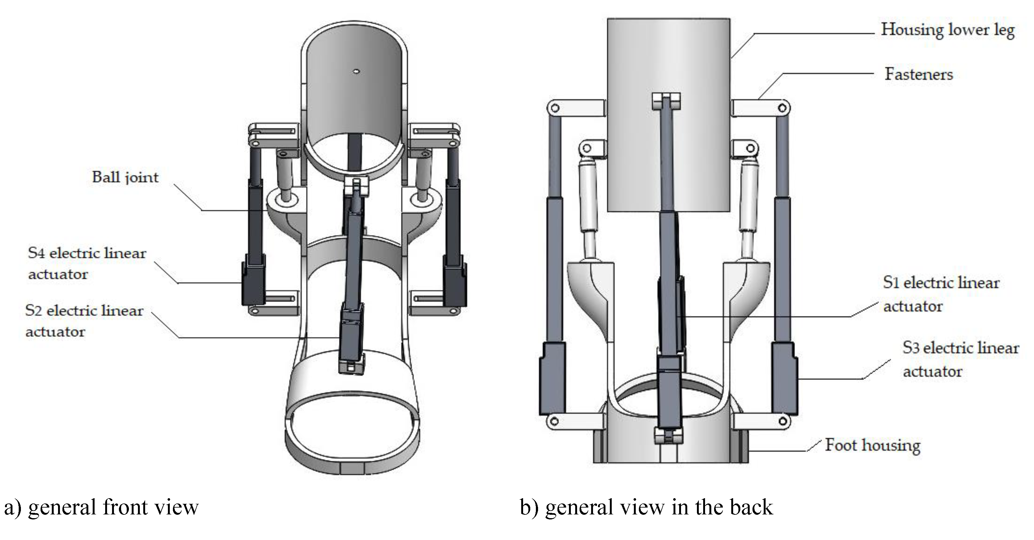
In this paper, the authors present a new exoskeleton solution designed specifically for the ankle joint. The mechanism uses electric linear actuators to facilitate user movements and increase mobility. The principal difference of the study is the presence of three degrees of freedom, promoting the recovery of the ankle joint and foot. In the exoskeleton structure, each degree of freedom has an individual function. The first degree of freedom refers to the vertical movement of the knee, allowing the leg to be raised and lowered. The second degree of freedom refers to the rotation around the ankle axis, which helps the foot to rotate in and out. The third degree of freedom provides upward and downward movement towards the heel, which is vital for everyday walking and balance. It is hypothesized that the solution proposed by the authors for developing an ankle exoskeleton will ensure its suitability for patients from different demographic groups and will be affordable. The device's performance was also evaluated and analyzed through virtual functional testing. Range of motion testing included assessments performed independently and in conjunction with normal subjects.
Comprising five sections, the article offers a comprehensive overview of ankle exoskeletons, including existing examples, kinematic principles, and modelling methodologies employed in the design process. Additionally, numerical characteristics are provided to validate the feasibility and efficacy of the proposed exoskeleton design.
By presenting a systematic exploration of relevant topics, this paper aims to contribute valuable insights to the field of assistive technologies and advance the development of innovative solutions for enhancing human mobility and rehabilitation practices.
3. Materials and Methods
This section elucidates the methodology employed in the development of the proposed and rehabilitation device, adhering to pertinent methodologies. Initially, it was imperative to ascertain the requisite movement criteria through an examination of the biomechanics of the human ankle joint, with particular emphasis on its mobility facets. After this, a device was introduced encompassing three degrees of freedom and outlining the structure of the control system. This phase culminated in the simulation of the performance characteristics of the exoskeleton, followed by a comprehensive discussion of the obtained results.
3.1. Anatomy of the Ankle Joint
The ankle joint complex, far from being a mere hinge joint, exhibits a sophisticated arrangement of multi-axial motions that work synergistically to support the intricacies of human locomotion. This complexity stems from a comprehensive understanding of the anatomical structure and kinematics of the human foot [44]. Comprising multiple interlocking joints, the human ankle is char acterized by the positioning of the talus bone at its core, flanked by the cuboid and navicular bones. The superior facet of the talus interfaces intricately with the tibia and fibula, delineating the upper ankle joint (UAJ). Through the UAJ, the ankle facilitates pivotal movements such as plantarflexion and rotational dorsiflexion, crucial for various activities ranging from walking to running [45].
The rotational capacity of the ankle joint is further enriched by the interplay of the forefoot bones, where interconnected articulations permit nuanced inversion and eversion rotations. This intricate arrangement ensures the adaptability of the ankle joint to dynamic changes in terrain and movement requirements [46].
Figure 1 serves as a visual aid, elucidating the complex interplay of these movements within the ankle joint.
The extensive body of literature dedicated to exploring ankle-foot anatomy [47] underscores the significance of comprehending the underlying structural and functional nuances. This knowledge base serves as a cornerstone for subsequent research endeavours to elucidate the intricate mechanisms governing ankle-foot movements and inform the development of robotic exoskeletons.
The complexity of rehabilitation is further compounded by the incorporation of anthropometric data pertaining to leg length and weight, which informs the design of the exoskeleton to ensure optimal fit and functionality. Prior to the manufacturing phase, meticulous calculations based on anthropometric measurements are undertaken to ascertain the precise length and weight of the foot, as delineated in Table 1.
In pursuit of creating robotic exoskeletons that accurately replicate natural ankle movements, a diverse array of studies [48,49,50,51,52,53] has been conducted. These studies delve into the biomechanical principles governing ankle kinematics, paving the way for innovative designs that enhance mobility and rehabilitation outcomes for individuals with impaired ankle function.
3.2. The Proposed Device
Rehabilitation devices, by virtue of their intimate interface with the human body, necessitate adherence to stringent design criteria. Since the ankle joint and foot function around a fixed axis, the mechanical structure of these devices must be precisely designed to replicate the anatomical contours of the human body. This design necessity allows the device to accommodate patients of different heights, weights, and ages, making the rehabilitation process more adaptable and effective.
Beyond considerations of safety and comfort, paramount importance is accorded to factors such as the normal range of motion and operational speed when interfacing with a patient undergoing rehabilitation. These parameters serve as crucial benchmarks in the design and implementation of rehabilitation devices, ensuring their efficacy and alignment with therapeutic objectives.
Figure 2 shows a CAD design indicating attachment points A, B, C, D for the linear actuators S1 and S2, with point H as the center point of the foot platform. Connections E and F on the support link the ball joint, serving as the guide between the shank and the foot platform. The calculated parameters of the CAD solution (Figure 2) are shown in Table 2.
These mechanisms feature three actuators in each kinematic chain, enabling two translational and one rotational movement.
To calculate the degrees of freedom, P.L. Chebyshev's structural formula for planar mechanisms is employed:
where is the degree of freedom; is the number of links; number of fifth-class couples (single movement couples) and number of pairs of the fourth class (two movable pairs).
The degrees of freedom for the planar mechanism can be determined using the Somov-Malyshev formula:
where , and are the is the number of kinematic pairs of the class with (6− i) degrees of mobility (i = 1, …, 5).
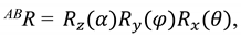
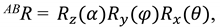
Based on the kinematics of the connections in the design of the exoskeleton (shown in Figure 3), the articulation angles of the joints can be described as follows:
The relative motion of the platform attached to the foot compared to the platform attached to the calf can be expressed as
When examining relative motion, it is important to consider the following three aspects: (a) ensuring constant tension in all actuators, (b) utilizing spherical hinges at the attachment points of the actuators to the platform, and (c) treating the actuators as prismatic joints with minimal axial deformation.
The points on which the drives on the platform attached to the ankle can be generically labelled , and the points on the platform attached to the foot can be labelled . Using the model in Figure 3, the vector equation of the node closure for each drive can be written as follows:
Rehabilitation exercises require the execution of homogeneous, slow, and controlled movements so that the patient feels the least stress or pain. Since these exercises are performed at a limited speed, inertial effects and movement dynamics can be ignored in the analyses. Therefore, static analysis can be used to evaluate the effectiveness of the robot.
The voltage in each drive is defined as as the product of the unit vector and its intensity, and the vector T here :
and
where and .
As previously stated, due to the spherical nature of the kinematic representation of the ankle joint and the unrestricted range of rotational movement, the reaction moment is a zero vector. Consequently, the complete equilibrium equation can be formulated accordingly:
The challenge in robot operation can be characterized by solving for torque based on the movement of the ankle joint.
According to the conceptual model of the ankle exoskeleton design shown in Figure 3, the electric linear actuator should integrate a system that coordinates the movement of the two interconnected skeletons thereby moving the ankle along with the exoskeleton. When assessing relative motion, it is crucial to consider the following three conditions: (a) ensuring constant tension in all actuators, (b) utilizing spherical hinges at the attachment points of the actuators to the platform, and (c) treating the actuators as prismatic joints with minimal axial deformation.
Figure 3.
Conceptual design of the ankle exoskeleton.
3.3. Performance Characteristics Simulation
A 3D modelling and simulation analysis was conducted within a virtual framework employing the SolidWorks Simulation software alongside the Motion Simulation adjunct. By applying an electric linear actuator input via SolidWorks Simulation, dynamic articulation of the ankle joint was achieved.
Furthermore, Figure 5 showcases the dorsal and plantar flexion movements of the ankle joint in a neutral position, providing a visual representation of simulated assisted movements facilitated by SolidWorks Simulation. Dorsal flexion exhibits a range of motion up to 20 degrees, with a simulated bending depicted in 15 degrees. On the other hand, plantar flexion demonstrates a range of motion spanning from 40 to 50 degrees, with a simulated bending capability of up to 20 degrees.
Figure 6 depicts a graph illustrating the relationship between angular acceleration and foot angle (). The graphical representation delineates notable features of the acceleration profile. A prominent peak is observed at the upper extremity of the motion, reaching a magnitude of 240 deg/s². Similarly, another significant peak, measuring 150 deg/s², is discernible near the lower limit of the motion trajectory. These distinctive peaks signify critical instances of rapid angular acceleration within the system under investigation.
Figure 7 depicts the driving force applied by the linear actuators, with F1 representing the force from the actuator on the front side of the leg, and F2 indicating the force from the actuator on the back side of the leg. Computational analysis shows that both forces, F1 and F2, achieve a magnitude of 0.8 N.
Figure 8 illustrates the components of linear displacement of the platform. The graph shows peaks in all directions, with maximum values reaching 100 deg/s² for the X-component and less than 85 deg/s² for the other components
Figure 9 shows the path traced by point H, positioned at the center of the platform. The displacement of this point along the Z-axis is 25.5 mm, and along the Y-axis, it reaches 74.6 mm, corresponding to an angle of +/- 8 degrees.
Figure 9.
The computed results of the simulated motion illustrated in Figure 4 are described in relation to the trajectory of point H on the foot platform.
Figure 9.
The computed results of the simulated motion illustrated in Figure 4 are described in relation to the trajectory of point H on the foot platform.

Figure 10.
Snapshot depicting simulated assisted motions in abduction and adduction.
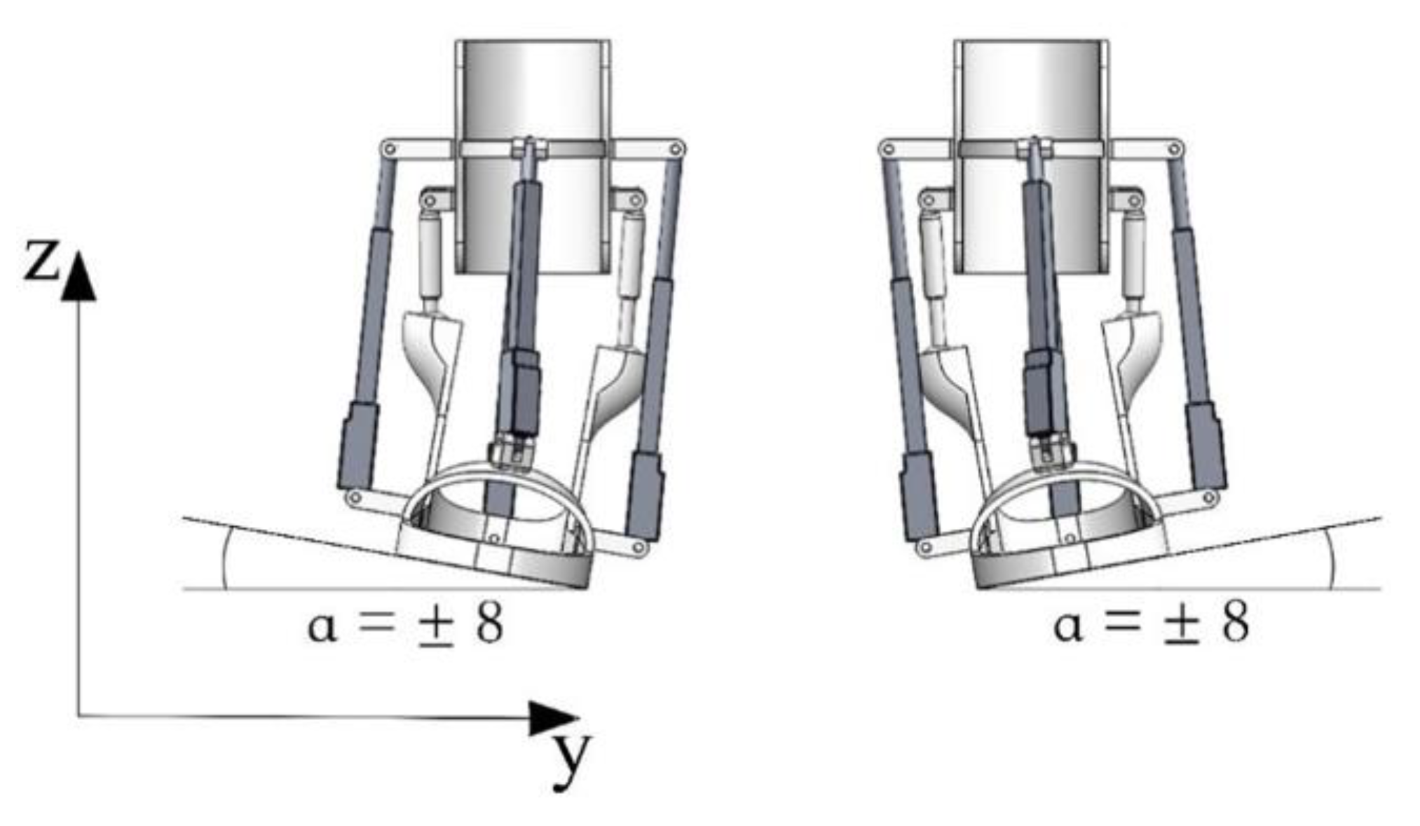
Figure 11 illustrates the angular acceleration with respect to the angle. The highest acceleration value, peaking at 23 deg/s², occurs near the top position. Angular acceleration quantifies the rate of change in both the magnitude and direction of angular velocity as the ankle joint moves with the exoskeleton.
Figure 12 presents the computed outcomes regarding the components of the platform's center of gravity position. The displacement of this point along the Y-axis is measured as -1.23 mm. In this study, the center of gravity signifies the stability of equilibrium positions of bodies and continuous media under the influence of gravity. This concept is particularly relevant in the analysis of material resistance, where it is utilized in conjunction with the Vereshchagin rule.
The driving force depicted in Figure 13 represents an external force exerted on the system to sustain motion. It symbolizes the force generated by linear actuators to induce movement in the ankle joint, exhibiting a maximum value of 45 Newton and a minimum value of 25 Newton in the motion simulation. Understanding this force is essential for comprehending the dynamics and mechanics of the system under investigation.
Figure 14 shows the components of linear displacement of the linear actuators. The graph indicates that movements in all directions reach peaks, with maximum values of 30 deg/s² for the Y-component and less than 25 deg/s² for the other components.
Figure 15 illustrates translational motion, also known as object motion, wherein each point of the object follows a parallel trajectory along straight lines. This stands in contrast to rotational motion, where an object rotates around a fixed axis. In the depicted scenario, over a 2-second interval, the upper part demonstrates a displacement of 3.5 m/s2, while the lower part exhibits a displacement of 2.8 m/s2. Understanding translational motion is paramount in the context of an exoskeleton as it provides the foundation for analysing the spatial movement, velocity, and acceleration of objects within the system.
The provided illustrations depict the simulated motions of both inversion and eversion attained via SolidWorks Simulation. The range of motion for inversion spans from 14.5 to 22.0 degrees, reaching 12 degrees in the depicted simulation. For eversion, the movement ranges from 10.0 to 17.0 degrees, with a simulated bending capability of up to 12 degrees.
Figure 16.
Snapshot illustrating simulated assisted motions in inversion and eversion.

Angular movements arise from changes in the angle between the bones that make up a joint, demonstrating the kinematic dynamics of the system. Figure 17 visually represents these angular movements. Within a 2-second interval, a torque of 45 Newton-seconds is observed, underscoring the dynamic forces involved in angular motion. Understanding such angular kinetics is fundamental in biomechanical analyses, offering insights into joint function and movement patterns.
Figure 18 presents the calculated outcomes of the platform's center of gravity components. The displacement of this point along the Z-axis measures 30 mm. In this study, the center of gravity signifies the stability of equilibrium positions for bodies and continuous media under the influence of gravity, particularly in applications such as material resistance where the Vereshchagin rule is applied.
The center of gravity (COG) of the human body represents a theoretical point where the force of gravity is considered to act. It is seen as the focal point around which the combined mass of the body is concentrated. However, due to the dynamic nature of human movement and variations in body proportions, the exact location of the center of gravity constantly shifts with changes in body position and limb arrangement.
The Euler angles depicted in Figure 19 elucidate a sequential amalgamation of passive rotations around the axes of a rotating coordinate system. This representation facilitates precise description and analysis of complex rotational movements, thereby enhancing our comprehension of dynamic systems and their behaviour.
Forward motion pertains to the displacement occurring along the orientation of an object or in alignment with the intended path of motion. This concept holds significance in biomechanics, where it delineates the progression of anatomical structures during locomotion. The accompanying Figure 20 illustrates that within a 2-second timeframe, a peak force of 35 Newtons is exerted, highlighting the biomechanical dynamics involved in ankle movement. Understanding such forces is instrumental in deciphering the intricacies of human locomotion and optimizing performance in various physical activities.
4. Results
4.1. Assembly of an Ankle Exoskeleton Prototype
The design results represent a novel approach to addressing mobility problems associated with ankle dysfunction by developing a prototype of a low-cost exoskeleton. The exoskeleton prototype is assembled to validate the developed concept in a practical application virtually. The primary and support structures of the exoskeleton prototype are fabricated using a Creality Ender-3 3D printer. The base of the ankle exoskeleton body is made of PLA, which contributes to the structural integrity and strength of the exoskeleton's outer shell. This is important because the prototype system must withstand the mechanical forces and loads generated by ankle joint movement while ensuring stable device performance during rehabilitation. When designing the exoskeleton body, ease of assembly was prioritized to provide comfort and convenience for clinicians and patients. Figure 21 shows the assembled prototype of the exoskeleton combining mechanical and electronic components. The weight of the prototype for each foot individually is 2.05 kg.
The prototype features specially placed attachment points that facilitate the smooth integration of various components, including actuators, sensors, and fastening mechanisms that secure the exoskeleton to the user's lower limb. Ergonomics plays a crucial role in the design of the body. Ergonomic considerations include reducing pressure points and optimizing fit and weight distribution to ensure user comfort. The appearance of the PLA exoskeleton body has been carefully designed to be aesthetically pleasing.
In its design, customization, durability, weight optimization, ergonomic considerations, safety features, and ease of assembly were prioritized. All these attributes combine to ensure the effectiveness, safety and comfort of the exoskeleton user in various rehabilitation and mobility applications. Table 3 summarizes the main device performance parameters used in the assembly of the exoskeleton prototype.
4.2. Solution for Control Design Unit
The control system of the robotic exoskeleton, driven by a linear electric actuator, incorporates position and power control units for the platform. This setup allows for generating the required torque for the robot's motion. Active training includes resistance mode and combination mode. In resistance mode, the motor applies resistance, necessitating extra effort from the user to move the platform. This mode also generates a counterforce to enhance joint strength. Conversely, in combination mode, the user's movement creates a torque opposing the applied force.
In contrast, passive assist mode relies solely on the motor for all leg movements on the platform, eliminating the need for user muscular activity. It encompasses voluntary and compulsory passive exercises, with the latter extending joint movement beyond the user's active range, necessitating motor assistance. This study focuses on the limited motion range within which the robot operates.
The sensor components in the system are divided into two primary groups. Control sensors, including IMU sensors, EMG sensors, and voltage sensors, deliver essential data such as angular position, platform position, real-time cable length, and voltage readings. Force sensors gauge user-applied force and discern intended platform manoeuvres. Additionally, a blood pressure transducer monitors ankle joint pressure, ensuring patient safety during rehabilitation.
The ankle exoskeleton's control scheme, depicted in the provided Figure 4. functions as follows:
- −
- Inputs to MCU (Microcontroller Unit): Received from various sources including a PC, Force-Sensitive Resistors (FSR), an EMG Sensor, and an IMU Sensor;
- −
- MCU Outputs: Processes inputs to control additional devices for enhanced functionality and a DC motor driver, which regulates a DC motor;
- −
- Ankle Joint Manipulation: The DC motor manipulates the ankle joint, enabling movement and support by the exoskeleton.
This flowchart illustrates the integration of hardware and software components to precisely control the ankle exoskeleton's movements, utilizing sensors for real-time feedback and adjustments to ensure safe and effective operation.
All the above-mentioned components of the prototype control system are interfaced with each other using an Arduino microcontroller, which serves as the central processor of the system. The Arduino receives signals from the sensors and converts them into commands for the actuators, which regulate the linear actuators. In addition, the microcontroller perform other functions such as data logging, processing sensor data, and communicating with other devices.
4.3. Experimental Study and Functional Tetting of the Prototype
Testing layout with main components of Ankle Exoskeleton shown in Figure 23 consists of a battery power supply (Power unit), ankle joint platform (exoskeletion prototype), drives, ball joint, microcontroller, drivers (Control unit system) and PC.
The control system unit, shown in Figure 24, consists of sensors that provide essential feedback to the control system, allowing it to adapt the signals applied to the electric linear actuators.
Actuonix linear actuators contain a built-in DC motor that can be controlled with the L298N driver. The L298N driver is used to control actuators as a direct current motor and contains two H-bridge channels, which allows you to control two motors simultaneously. The actuator receives a rated voltage of 12V, corresponding to its specification.
To ensure that the required specifications were met after the design and assembly of the exoskeleton prototype, functional testing of the device was performed to evaluate the performance of the four linear electric actuators. The results of the functional testing evaluated the exoskeleton prototype's functionality, usability and safety under various loads and conditions.
Modelling the dynamics of an ankle rehabilitation device considering three basic motions is a challenging task due to the nonlinear nature of the overall system; in this case, the main objective of the mechatronic system of the exoskeleton prototype is to control the devices based on simplified models, thus increasing their robustness to external influences. With this in mind, the separate dynamics required to maintain the basic movements of the ankle rehabilitation device were initially investigated. This is because, in passive rehabilitation, specific exercises are first performed to ensure stability and functionality of the ankle joint.
Figure 25 shows a device used for experimental functional testing of the ankle exoskeleton during movements in the dorsal and plantar flexion. The test evaluates the effectiveness of the exoskeleton and the operation of the actuators.
All dorsiflexion-plantarflexion movements are recorded by the IMU BMI160 sensor.
Figure 26 shows the translation motion of the foot platform during dorsiflexion–plantarflexion movements over time. The motion fluctuates between approximately -10 and 70 newton-seconds, indicating the force exerted in different directions. This periodic pattern repeats roughly every 14 seconds, reflecting the cyclical nature of these movements.
Figure 27 shows the angular displacement of the foot platform during dorsiflexion–plantarflexion movements over time. The displacement ranges from approximately 10 to -10 degrees, indicating the range of motion of the ankle joint. This periodic pattern reflects the regular cycle of these movements, which is important for understanding the dynamics of foot motion.
Figure 28 shows the angular acceleration of the foot platform during dorsiflexion plantar flexion movements over time. The angular acceleration ranges from approximately -1 to 9 deg/s2. This pattern repeats approximately every 2 seconds, indicating a regular cycle of movement.
Figure 29 shows the velocity of the foot platform during dorsiflexion movements. The velocity ranges from approximately 35 mm/sec to -5 mm/sec, indicating a periodicity of the movement. This pattern repeats approximately every 4 seconds, reflecting the cyclical nature of the foot platform velocity during these movements.
Figure 30 shows the reaction force of the S1 actuator during dorsiflexion plantar flexion movements over time. The force starts at 0 Newtons, peaks at about 20 Newtons at 2 seconds, returns to zero, then increases again to just over 50 Newtons at about 8 seconds before returning to 0. This indicates a change in the force exerted by the actuator during these movements.
This clearly demonstrates that the result values are approaching the maximum actuator force value of 50 N.
In functional testing the actuators have current values of: S1 - 0.1 A and S2 - 0.06 A. This is due to the fact that the drives move the platform back and forth alternately, repeating the movements of the input and output as shown in Figure 31, where the current values are given in drives S1 and S2.
Actuonix, Miniature Linear Actuators L16 [53] used in exoskeleton has a compact and lightweight design, making it ideal for integration into exoskeleton without significant increase in volume or weight.
In this pilot study, the functional testing results demonstrate the ability of the exoskeleton prototype to generate controlled linear and angular movements with significant accelerations in a short period of time. This highlights its potential to improve mobility, stability and support during dynamic activities.
The functional testing results obtained during the experiment play a key role in improving the exoskeleton design and optimizing its real-world performance.
5. Conclusions
In this study, a virtual model of the proposed exoskeleton was developed and simulated in SolidWorks Motion&Simulation software. Additionally, a low-cost prototype of the exoskeleton for ankle rehabilitation was created and tested. The prototype represents an innovative approach to address mobility problems associated with ankle joint dysfunction. The study also focused on the complex anatomy and kinematics of the ankle joint, which was considered in developing a comprehensive computer-aided design system model that allows simulation analysis to evaluate the viability and performance of the prototype design. It has four linear electric actuators that provide three bare ankle joint movements: dorsal flexion and plantar flexion, adduction, abduction, and inversion, eversion. The presence of 3DOFs in the prototype has the ability to mimic ankle joint motion, allowing for a smoother and more natural walking motion. This helps to speed up the recovery process for patients with disabilities. The use of modern 3D printing technologies and the choice of available materials to assemble the exoskeleton prototype has increased its cost-effectiveness. This reduces initial production costs and facilitates maintenance and repair of the device during operation, an essential key factor for long-term operation and maintenance of its performance. The use of modern sensors and electronics allows the exoskeleton prototype to accurately track movements and adapt the functionality of the device to the needs of the user, which makes it attractive to a wide range of users.
The exoskeleton's control system, which includes positional and force control units, enables the generation of the required torque for the robot's movements. The use of sensors to monitor angular position and force ensures accurate and safe operation of the device. Once the design phase is complete, the prototype assembled to validate the concept in a practical environment. Future research will focus on conducting experimental studies to evaluate the functionality and performance of the exoskeleton in real-world conditions. This integrative approach to design and testing has the potential to significantly improve rehabilitation methods and the quality of life for people with ankle mobility impairments.
Future endeavors will focus on conducting experimental characterization studies, providing invaluable insights into the exoskeleton's functionality and performance under real-world conditions. This iterative approach, combining simulation-based design refinement with practical validation through prototyping, holds immense promise in the development of advanced assistive technologies.
Author Contributions
Conceptualization, G.S. and N.Zh.; methodology, N.Zh and G.T.; software, U.A.; validation, A.S., Y.N.; formal analysis, G.S.; investigation, G.T.; resources, N.Zh.; data curation, A.U.; writing—original draft preparation, G.S., G.T.; writing—review and editing, N.Zh.; visualization, Y.N. A.N.; supervision, G.S.; project administration, G.S.; funding acquisition, G.S. All authors have read and agreed to the published version of the manuscript.
Funding
This research was funded by the Ministry of Science and Higher Education of the Republic of Kazakhstan, Grant № AP13268857.
Data Availability Statement
Not applicable.
Conflicts of Interest
The authors declare no conflicts of interest.
References
- Colak, S.; Orha, A.T.; Yener, M.D.; Colak, T.; Bamac, B.; Colak, E. Musculoskeletal system related complaint: Is there any effect of sports ergonomics and lack of core stabilization exercises, Science & Sports, Volume 36, Issue 6, 2021, Pages 481.e1-481.e7, ISSN 0765-1597. [CrossRef]
- World Health Organization (WHO), Rehabilitation: Key facts, https://www.who.int/news-room/fact-sheets/detail/rehabilitation (Published 22 April 2024).
- World Health Organization (WHO), Musculoskeletal health: Key facts, https://www.who.int/news-room/fact-sheets/detail/musculoskeletal-conditions (Published 14 July 2022).
- De Bock, S.; Ghillebert, J.; Govaerts, R.; Tassignon, B.; Rodriguez-Guerrero, C.; Crea, S.; Veneman, J.; Geeroms, J.; Meeusen, R.; De Pauw, K. Benchmarking occupational exoskeletons: An evidence mapping systematic review, Applied Ergonomics, Volume 98, 2022, 103582, ISSN 0003-6870. [CrossRef]
- World Health Organization (WHO), Rehabilitation 2030 initiative. https://www.who.int/initiatives/rehabilitation-2030.
- Chen, C.; Lv, J.; Xu, Z. A Multi-Indicator evaluation method for Human-Machine effectiveness of lower limb wearable exoskeleton, Biomedical Signal Processing and Control, Volume 91, 2024, 105976, ISSN 1746-8094. [CrossRef]
- S.K. Hasan, Anoop K. Dhingra, Biomechanical design and control of an eight DOF human lower extremity rehabilitation exoskeleton robot, Results in Control and Optimization, Volume 7, 2022, 100107, ISSN 2666-7207. [CrossRef]
- Ye Huo, M. Niaz Khan, Zh. Feng Shao, Yu Pan, Development of a novel cable-driven parallel robot for full-cycle ankle rehabilitation, Mechatronics, Volume 101, 2024, 103210, ISSN 0957-4158. [CrossRef]
- Bhat, A.; Rao, V.S.; Jayalakshmi, N.S. Review of the Evolution of Magnetorheological Fluid-Based Rehabilitative Devices: From the Perspective of Modeling, Sensors and Control Strategies," in IEEE Access, vol. 11, pp. 88759–88777, 2023. [CrossRef]
- T. Zhang, Ye Tian, Y. Yin, W. Sun, L. Tang, R. Tang, Y. Tian, Sh. Gong, S. Tian, Efficacy of an Omaha system-based remote ergonomic intervention program on self-reported work-related musculoskeletal disorders (WMSDs) — A randomized controlled study, Heliyon, Volume 10, Issue 2, 2024, e24514, ISSN 2405-8440. [CrossRef]
- D. Hu, C. D. Hu, C. Xiong, T. Wang, T. Zhou, J. Liang and Y. Li, Modulating Energy Among Foot-Ankle Complex With an Unpowered Exoskeleton Improves Human Walking Economy, in IEEE Transactions on Neural Systems and Rehabilitation Engineering, vol. 30, pp. 1961–1970, 2022. [CrossRef]
- Wen-Jun Tu, Bao-Hua Chao, Lin Ma, Feng Yan, Lei Cao, Hancheng Qiu, Xun-Ming Ji, Long-De Wang, Case-fatality, disability and recurrence rates after first-ever stroke: A study from bigdata observatory platform for stroke of China, Brain Research Bulletin, Volume 175, 2021, Pages 130-135, ISSN 0361-9230. [CrossRef]
- Lloyd, A.; Bannigan, K.; Sugavanam, T.; Freeman, J. Experiences of stroke survivors, their families and unpaid carers in goal setting within stroke rehabilitation: a systematic review of qualitative evidence. JBI Database System Rev Implement Rep. 2018, 16, 1418–1453. [Google Scholar] [CrossRef] [PubMed]
- Moosa, A.; Osama, D.; Alnidawi, F.; Algillidary, S.; Hussein, A.; Das, P. Risk Factors, Incidence, and Outcome of Stroke: A Retrospective Cross-Sectional Hospital-Based Study Comparing Young Adults and Elderly. Cureus. 2023, 15, e40614. [Google Scholar] [CrossRef] [PubMed] [PubMed Central]
- Otálora, S.; Ballen-Moreno, F.; Arciniegas-Mayag, L.; Cifuentes, C.A.; Múnera, M. Biomechanical Effects of Adding an Ankle Soft Actuation in a Unilateral Exoskeleton. Biosensors 2022, 12, 873. [Google Scholar] [CrossRef] [PubMed]
- Jiang, J.; Chen, P.; Peng, J.; Qiao, X.; Zhu, F.; Zhong, J. Design and Optimization of Lower Limb Rehabilitation Exoskeleton with a Multiaxial Knee Joint. Biomimetics 2023, 8, 156. [Google Scholar] [CrossRef]
- Weber, L.; Voldsgaard, N.H.; Holm, N.J.; Schou, L.H.; Biering-Sørensen, F.; Møller, T. Exploring the contextual transition from spinal cord injury rehabilitation to the home environment: a qualitative study. Spinal Cord. 2021, 59, 336–346. [Google Scholar] [CrossRef] [PubMed] [PubMed Central]
- Biering-Sørensen, F.; Noonan, V.K. Standardization of Data for Clinical Use and Research in Spinal Cord Injury. Brain Sci. 2016, 6, 29. [Google Scholar] [CrossRef] [PubMed] [PubMed Central]
- World Health Organization (WHO), Spinal cord injury: Key facts, https://www.who.int/ru/news-room/fact-sheets/detail/spinal-cord-injury, (Published 16 April 2024).
- Yana He, Yuxuan Xu, Minghang Hai, Yang Feng, Penghao Liu, Zan Chen, Wanru Duan, Exoskeleton-Assisted Rehabilitation and Neuroplasticity in Spinal Cord Injury, World Neurosurgery, Volume 185, 2024, Pages 45-54, ISSN 1878-8750. [CrossRef]
- Chaoyang Zhang, Ning Li, Xiali Xue, Xia Lu, Danjie Li, Qiaomei Hong, Effects of lower limb exoskeleton gait orthosis compared to mechanical gait orthosis on rehabilitation of patients with spinal cord injury: A systematic review and future perspectives, Gait & Posture, Volume 102, 2023, Pages 64-71, ISSN 0966-6362. [CrossRef]
- Liviu Cristian Chiș, Monica Copotoiu, Liviu Moldovan, Different Types of Exoskeletons can Improve the Life of Spinal Cord Injury’s Patients – a Meta-Analysis, Procedia Manufacturing, Volume 46, 2020, Pages 844-849, ISSN 2351-9789. [CrossRef]
- C. -F. Chen et al., "Development and Hybrid Control of an Electrically Actuated Lower Limb Exoskeleton for Motion Assistance," in IEEE Access, vol. 7, pp. 169107–169122, 2019. [CrossRef]
- J. -H. Woo et al., "Machine Learning Based Recognition of Elements in Lower-Limb Movement Sequence for Proactive Control of Exoskeletons to Assist Lifting," in IEEE Access, vol. 11, pp. 127107–127118, 2023. [CrossRef]
- M. Lazzaroni et al., "Improving the Efficacy of an Active Back-Support Exoskeleton for Manual Material Handling Using the Accelerometer Signal," in IEEE Robotics and Automation Letters, vol. 7, no. 3, pp. 7716–7721, July 2022. [CrossRef]
- U. Heo, J. U. Heo, J. Feng, S. J. Kim and J. Kim, "sEMG-Triggered Fast Assistance Strategy for a Pneumatic Back Support Exoskeleton," in IEEE Transactions on Neural Systems and Rehabilitation Engineering, vol. 30, pp. 2175–2185, 2022. [CrossRef]
- S. Kim, D. S. Kim, D. Srinivasan, M. A. Nussbaum and A. Leonessa, "Human Gait During Level Walking With an Occupational Whole-Body Powered Exoskeleton: Not Yet a Walk in the Park," in IEEE Access, vol. 9, pp. 47901–47911, 2021. [CrossRef]
- Delahunt, E.; Remus, A. Risk Factors for Lateral Ankle Sprains and Chronic Ankle Instability. J Athl Train 2019, 54, 611–616. [Google Scholar] [CrossRef]
- Wang, X.; Qiu, J.; Fong, D.T.P. The applications of wearable devices in the rehabilitation of ankle injuries: A systematic review and meta-analysis, Medicine in Novel Technology and Devices, Volume 17, 2023, 100210, ISSN 2590-0935. [CrossRef]
- Narayan, J.; Auepanwiriyakul, C.; Jhunjhunwala, S.; Abbas, M.; Dwivedy, S.K. Hierarchical Classification of Subject-Cooperative Control Strategies for Lower Limb Exoskeletons in Gait Rehabilitation: A Systematic Review. Machines 2023, 11, 764. [Google Scholar] [CrossRef]
- Weber, L.; Voldsgaard, N.H.; Holm, N.J.; Schou, L.H.; Biering-Sørensen, F.; Møller, T. Exploring the contextual transition from spinal cord injury rehabilitation to the home environment: a qualitative study. Spinal Cord. 2021, 59, 336–346. [Google Scholar] [CrossRef] [PubMed] [PubMed Central]
- Qiu, S.; Pei, Z.; Wang, C.; et al. Systematic Review on Wearable Lower Extremity Robotic Exoskeletons for Assisted Locomotion. J Bionic Eng 2023, 20, 436–469. [Google Scholar] [CrossRef]
- Ebers, M.R.; Rosenberg, M.C.; Kutz, J.N.; Steele, K.M. A machine learning approach to quantify individual gait responses to ankle exoskeletons. Journal of Biomechanics 2023, 157, 111695. [Google Scholar] [CrossRef] [PubMed]
- Hussain, F.; Goecke, R.; Mohammadian, M. Exoskeleton robots for lower limb assistance: A review of materials, actuation, and manufacturing methods. Proceedings of the Institution of Mechanical Engineers, Part H: Journal of Engineering in Medicine. 2021, 235, 1375–1385. [Google Scholar] [CrossRef] [PubMed]
- Rojek, I.; Dorożyński, J.; Mikołajewski, D.; Kotlarz, P. Overview of 3D Printed Exoskeleton Materials and Opportunities for Their AI-Based Optimization. Appl. Sci. 2023, 13, 8384. [Google Scholar] [CrossRef]
- W. -Z. Li, G. -Z. Cao and A. -B. Zhu, "Review on Control Strategies for Lower Limb Rehabilitation Exoskeletons," in IEEE Access, vol. 9, pp. 123040–123060, 2021. [CrossRef]
- M. Dong et al., "A New Ankle Robotic System Enabling Whole-Stage Compliance Rehabilitation Training," in IEEE/ASME Transactions on Mechatronics, vol. 26, no. 3, pp. 1490–1500, June 2021. [CrossRef]
- Qu, S.; Li, R.; Yao, W.; Ma, C.; Guo, Z. Structure Design, Kinematics Analysis, and Effect Evaluation of a Novel Ankle Rehabilitation Robot. Appl. Sci. 2023, 13, 6109. [Google Scholar] [CrossRef]
- Murariu, M.; Paint, Y.; Murariu, O.; Laoutid, F.; Dubois, P. Tailoring and Long-Term Preservation of the Properties of PLA Composites with "Green" Plasticizers. Polymers 2022, 14, 4836. [Google Scholar] [CrossRef] [PubMed] [PubMed Central]
- M. Dong, J. M. Dong, J. Li, X. Rong, W. Fan, Y. Kong and Y. Zhou, "Compliant physical interaction to enhance rehabilitation training of a parallel ankle robotic system," 2020 Chinese Automation Congress (CAC), Shanghai, China, 2020, pp. 2191–2196. [CrossRef]
- Li, J.; Zuo, S.; Zhang, L.; Dong, M.; Zhang, Z.; Tao, C.; Ji, R. (April 13, 2020). Mechanical Design and Performance Analysis of a Novel Parallel Robot for Ankle Rehabilitation. ASME. J. Mechanisms Robotics. 2020, 12, 051007. [Google Scholar] [CrossRef]
- Dong, M.; Zhou, Y.; Li, J.; Rong, X.; Fan, W.; Zhou, X.; Kong, Y. State of the art in parallel ankle rehabilitation robot: a systematic review. J Neuroeng Rehabil. 2021, 18, 52. [Google Scholar] [CrossRef] [PubMed] [PubMed Central]
- Abarca, V.E.; Elias, D.A. A Review of Parallel Robots: Rehabilitation, Assistance, and Humanoid Applications for Neck, Shoulder, Wrist, Hip, and Ankle Joints. Robotics 2023, 12, 131. [Google Scholar] [CrossRef]
- Anand Prakash, A. Anatomy of Ankle Syndesmotic Ligaments: A Systematic Review of Cadaveric Studies. Foot Ankle Spec. 2020, 13, 341–350. [Google Scholar] [CrossRef] [PubMed]
- Bergman, C.; Morin, M.; Lawson, K. Anatomy, Classification, and Management of Ankle Fractures Involving the Posterior Malleolar Fragment: A Literature Review. Foot Ankle Orthop. 2019, 4, 2473011419887724. [Google Scholar] [CrossRef] [PubMed] [PubMed Central]
- Faragó, P.; Grama, L.; Farago, M.-A.; Hintea, S. A Novel Wearable Foot and Ankle Monitoring System for the Assessment of Gait Biomechanics. Appl. Sci. 2021, 11, 268. [Google Scholar] [CrossRef]
- Gupta, R.; Grove, K.; Wei, A.; Lee, J.; Akkouch, A. Ankle and Foot Arthroplasty and Prosthesis: A Review on the Current and Upcoming State of Designs and Manufacturing. Micromachines 2023, 14, 2081. [Google Scholar] [CrossRef] [PubMed]
- Nursultan, Z.; Marco, C.; Balbayev, G. A Portable Robotic System for Ankle Joint Rehabilitation. Electronics 2023, 12, 4271. [Google Scholar] [CrossRef]
- Russo, M.; Ceccarelli, M. Analysis of a Wearable Robotic System for Ankle Rehabilitation. Machines 2020, 8, 48. [Google Scholar] [CrossRef]
- Gonçalves, R.S.; Rodrigues, L.A.O.; Humbert, R.; Carbone, G. A User-Friendly Nonmotorized Device for Ankle Rehabilitation. Robotics 2023, 12, 32. [Google Scholar] [CrossRef]
- Doroftei, I.; Cazacu, C.-M.; Alaci, S. Design and Experimental Testing of an Ankle Rehabilitation Robot. Actuators 2023, 12, 238. [Google Scholar] [CrossRef]
- Meng, Q.; Liu, G.; Xu, X.; Meng, Q.; Yu, H. Design and Analysis of a Supine Ankle Rehabilitation Robot for Early Stroke Recovery. Machines 2023, 11, 787. [Google Scholar] [CrossRef]
- Actuonix, Miniature Linear Actuators L16, user manual, 2024. URL: https://www.actuonix.com/linear-servos-for-rc, visited on 17/07/2024.
Figure 1.
Main foot rotations around the two axes of the ankle.

Figure 2.
CAD model of the ankle exoskeleton components and their assembly in SolidWorks.
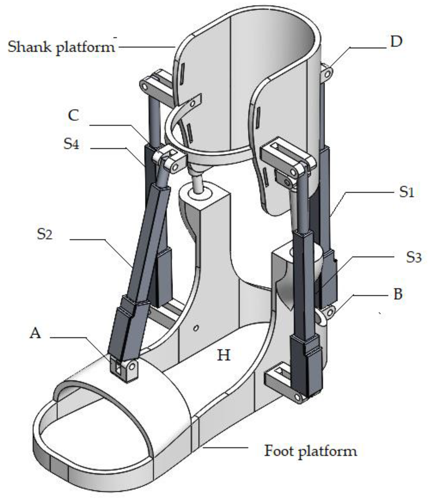
Figure 5.
A snapshot showcasing simulated assisted movements in dorsiflexion and plantarflexion.
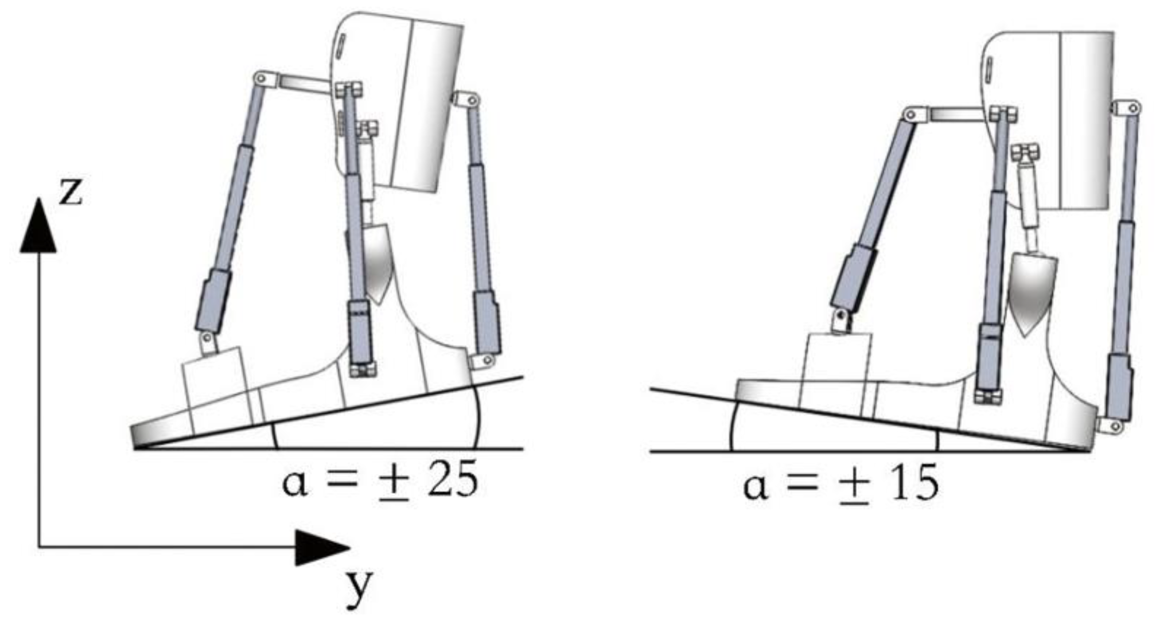
Figure 6.
The computed results of the simulated motion portrayed in Figure 5 are presented in terms of the α angle of the foot platform.
Figure 6.
The computed results of the simulated motion portrayed in Figure 5 are presented in terms of the α angle of the foot platform.

Figure 7.
The computed results of the simulated motion depicted in Figure 5 are expressed in terms of the driving force exerted by the linear actuators.
Figure 7.
The computed results of the simulated motion depicted in Figure 5 are expressed in terms of the driving force exerted by the linear actuators.

Figure 8.
The input data for the simulated motion depicted in Figure 5 pertains to the displacement of linear actuators.
Figure 8.
The input data for the simulated motion depicted in Figure 5 pertains to the displacement of linear actuators.
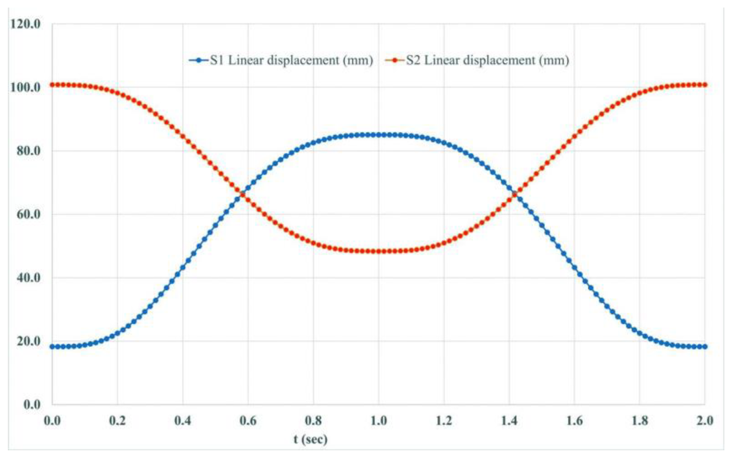
Figure 11.
The computed results of the simulated motion depicted in Figure 4 are expressed in terms of the angle of the foot platform.
Figure 11.
The computed results of the simulated motion depicted in Figure 4 are expressed in terms of the angle of the foot platform.
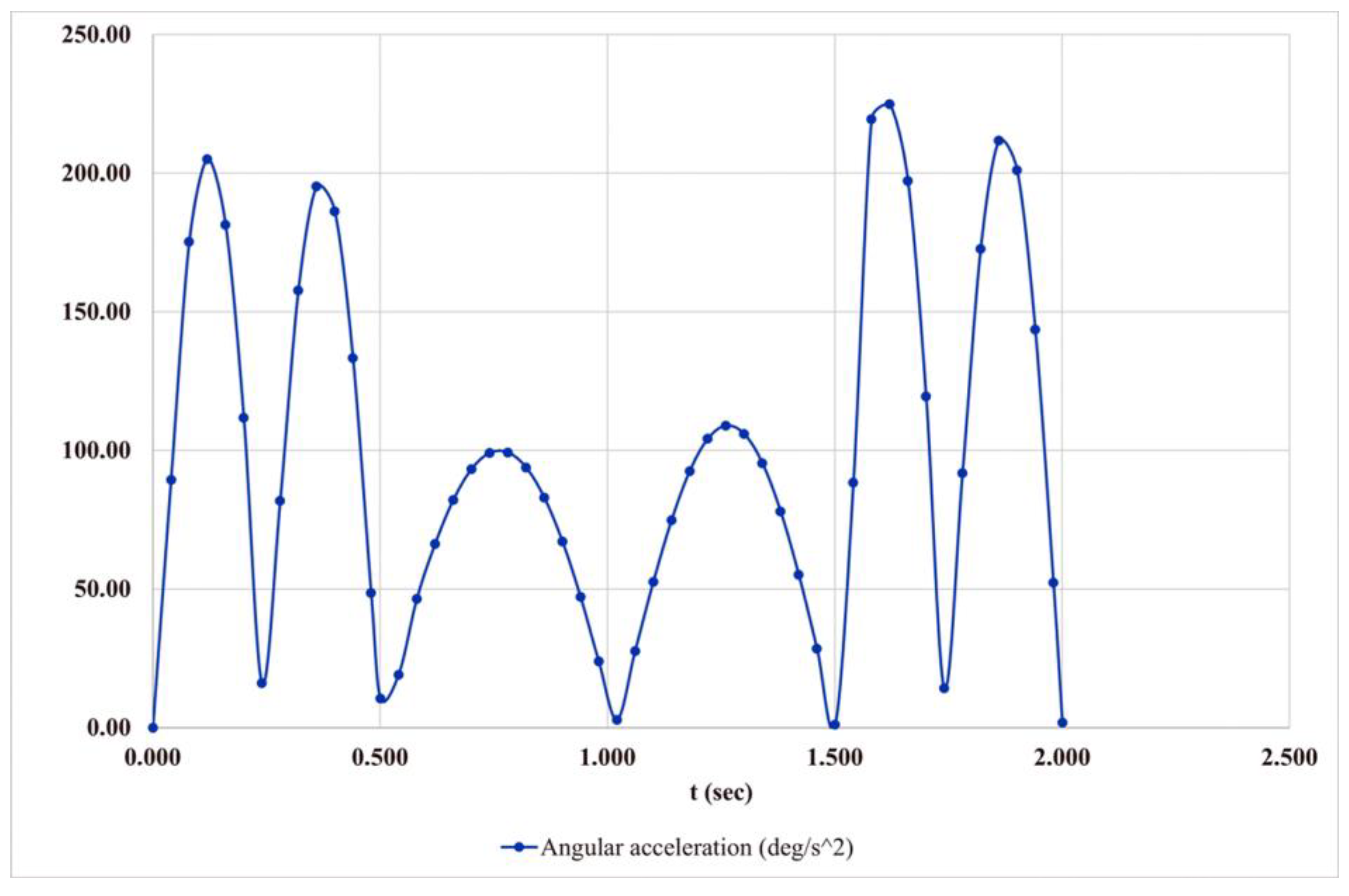
Figure 12.
The input data for the simulated motion depicted in Figure 10 includes the center of gravity position.
Figure 12.
The input data for the simulated motion depicted in Figure 10 includes the center of gravity position.

Figure 13.
The calculated results of the motion simulation, as shown in Figure 10, are presented in terms of the driving force.
Figure 13.
The calculated results of the motion simulation, as shown in Figure 10, are presented in terms of the driving force.
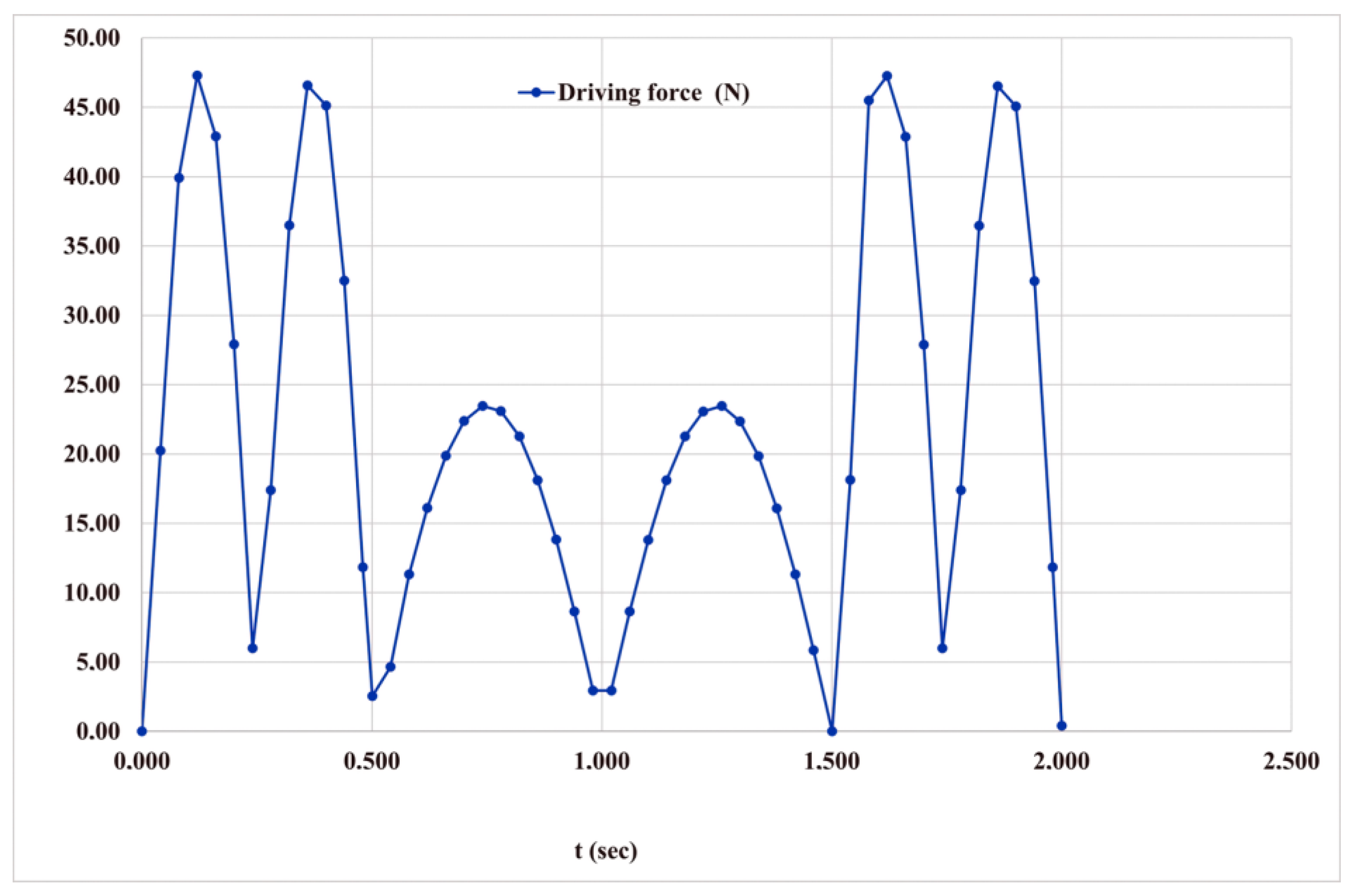
Figure 14.
The computed results of the simulated motion depicted in Figure 10 are presented in terms of the displacement of linear actuators.
Figure 14.
The computed results of the simulated motion depicted in Figure 10 are presented in terms of the displacement of linear actuators.

Figure 15.
The calculated results of the simulated motion depicted in Figure 10 are presented in terms of translational motion.
Figure 15.
The calculated results of the simulated motion depicted in Figure 10 are presented in terms of translational motion.

Figure 17.
The results of motion modelling utilizing linear actuators are depicted in Figure 16, showcasing angular movements.
Figure 17.
The results of motion modelling utilizing linear actuators are depicted in Figure 16, showcasing angular movements.
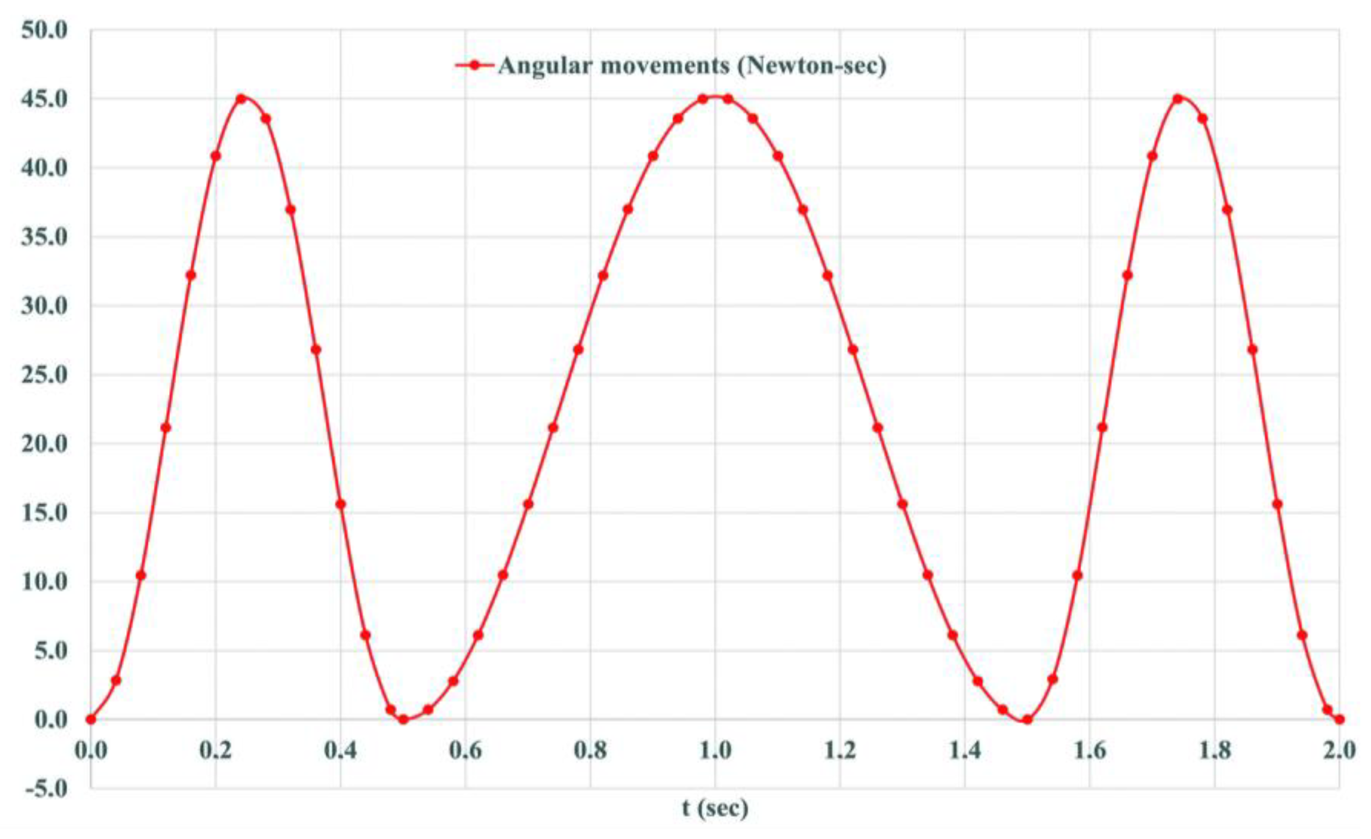
Figure 18.
Simulation results for the motion in Figure 16 by center of gravity.
Figure 18.
Simulation results for the motion in Figure 16 by center of gravity.
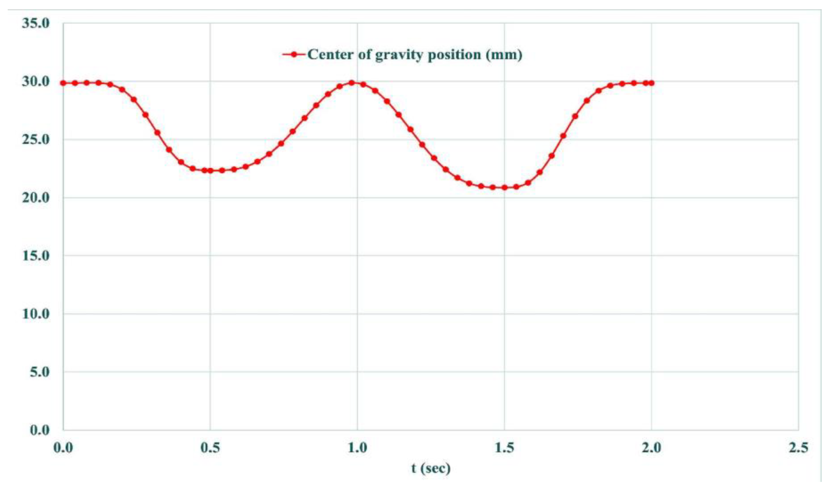
Figure 19.
The input data for the simulated motion depicted in Figure 16 is expressed in terms of Euler angles.
Figure 19.
The input data for the simulated motion depicted in Figure 16 is expressed in terms of Euler angles.
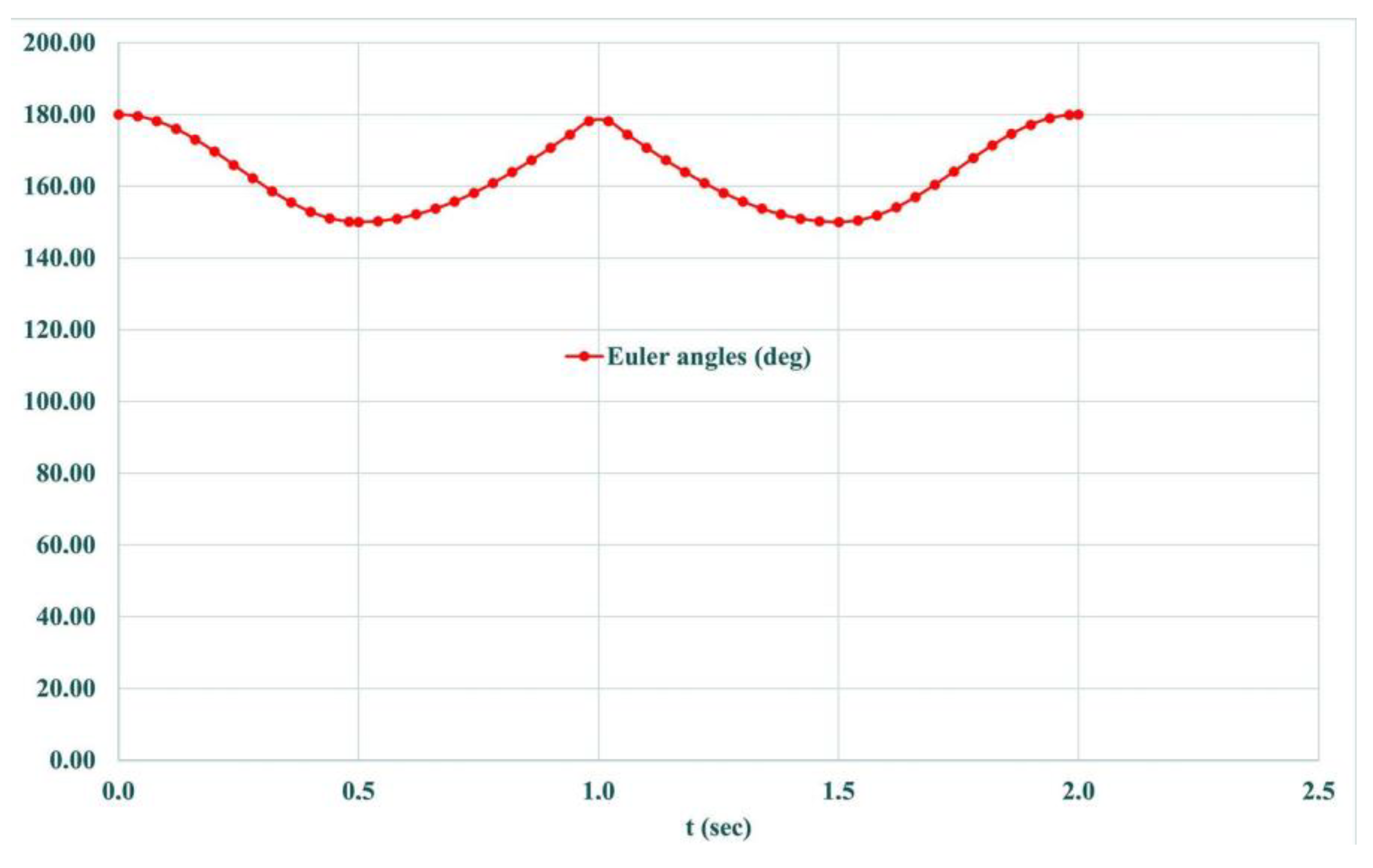
Figure 20.
Forward movement.
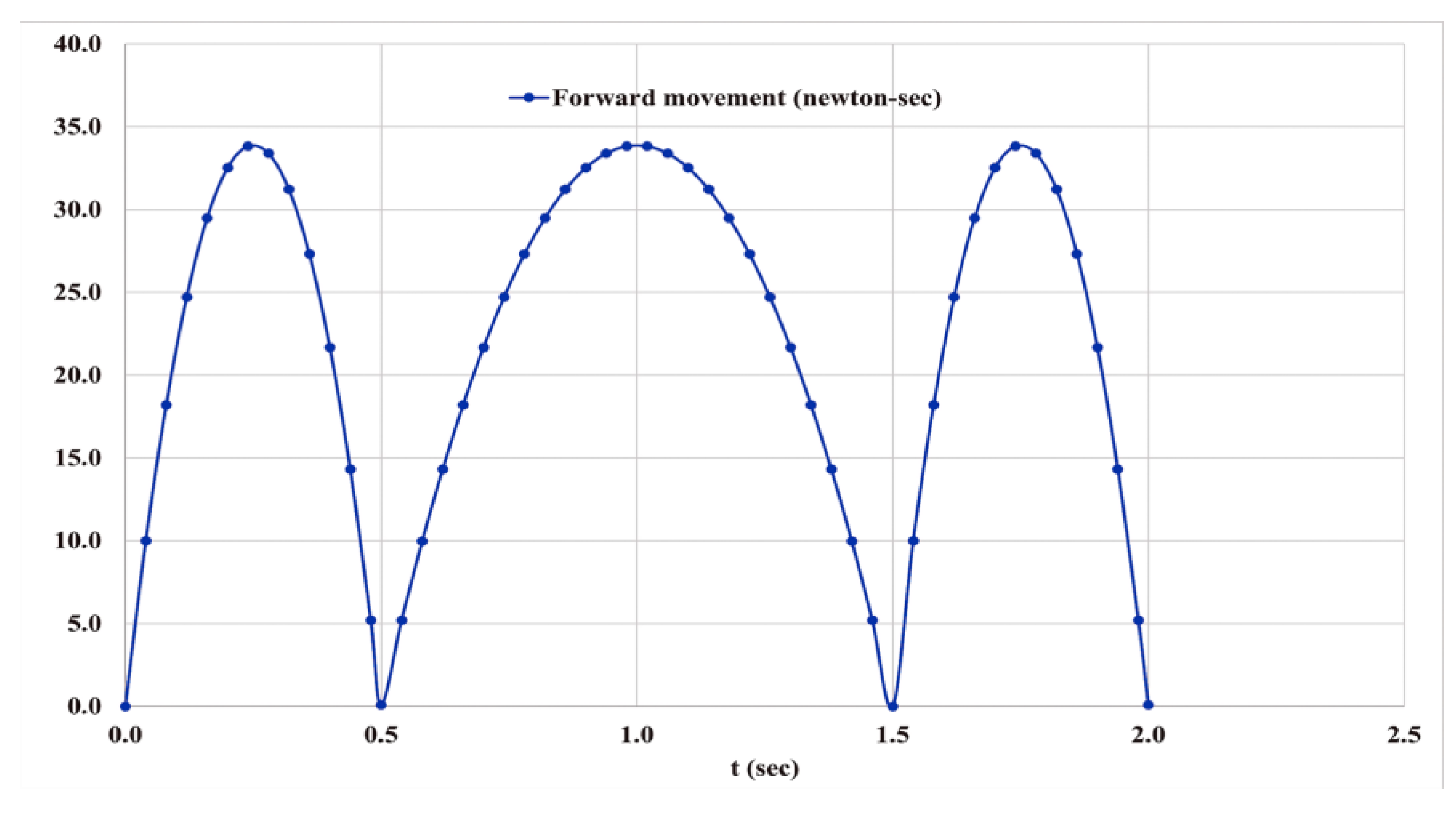
Figure 21.
General view of the exoskeleton prototype.

Figure 22.
A scheme for control design in ankle joint exoskeleton.

Figure 23.
Testing layout with main components of Ankle Exoskeleton.
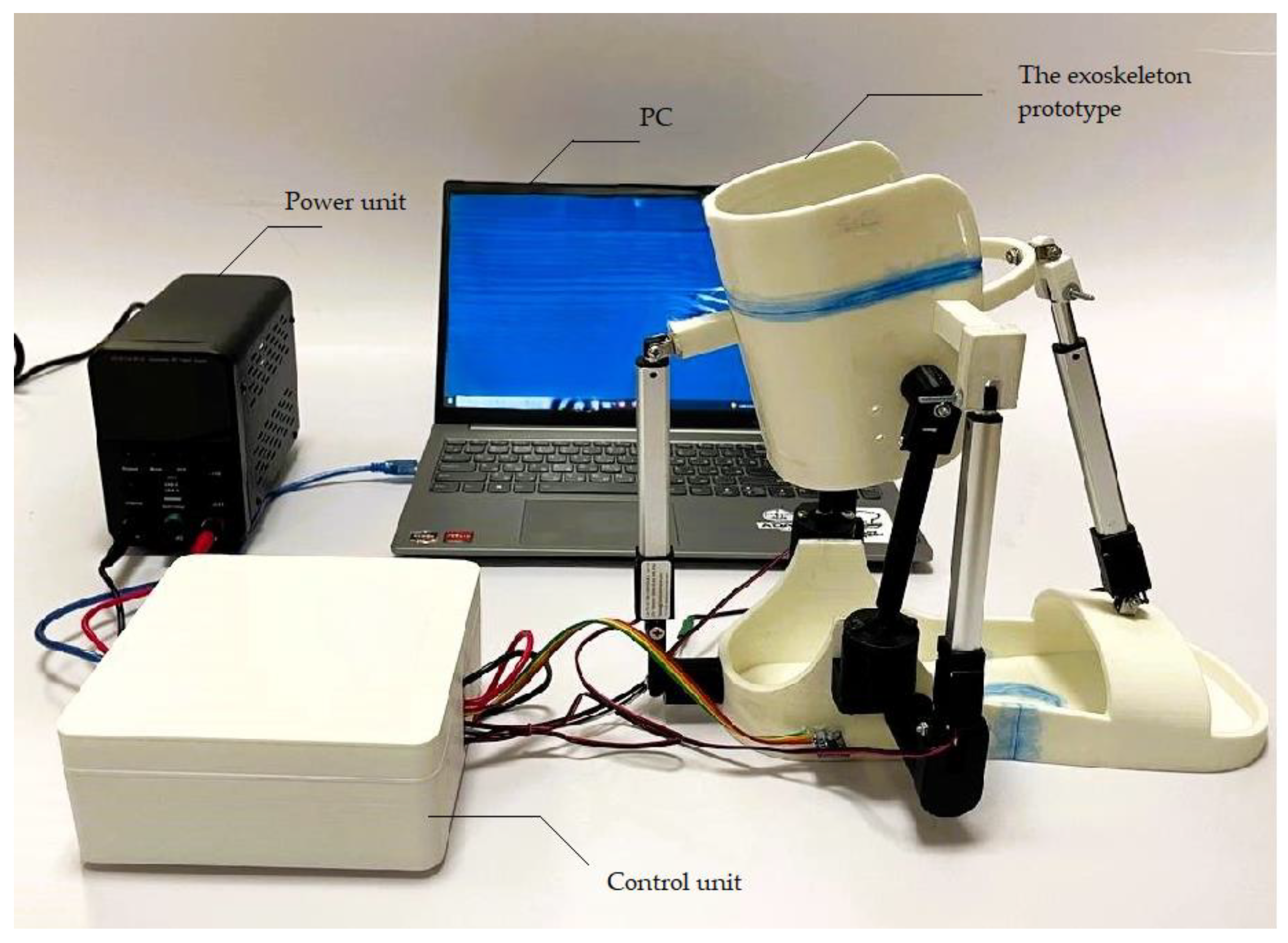
Figure 24.
The control system unit.

Figure 25.
Experiment of functional testing of the ankle joint exoskeleton during linear motion in dorsiflexion and plantarflexion.
Figure 25.
Experiment of functional testing of the ankle joint exoskeleton during linear motion in dorsiflexion and plantarflexion.
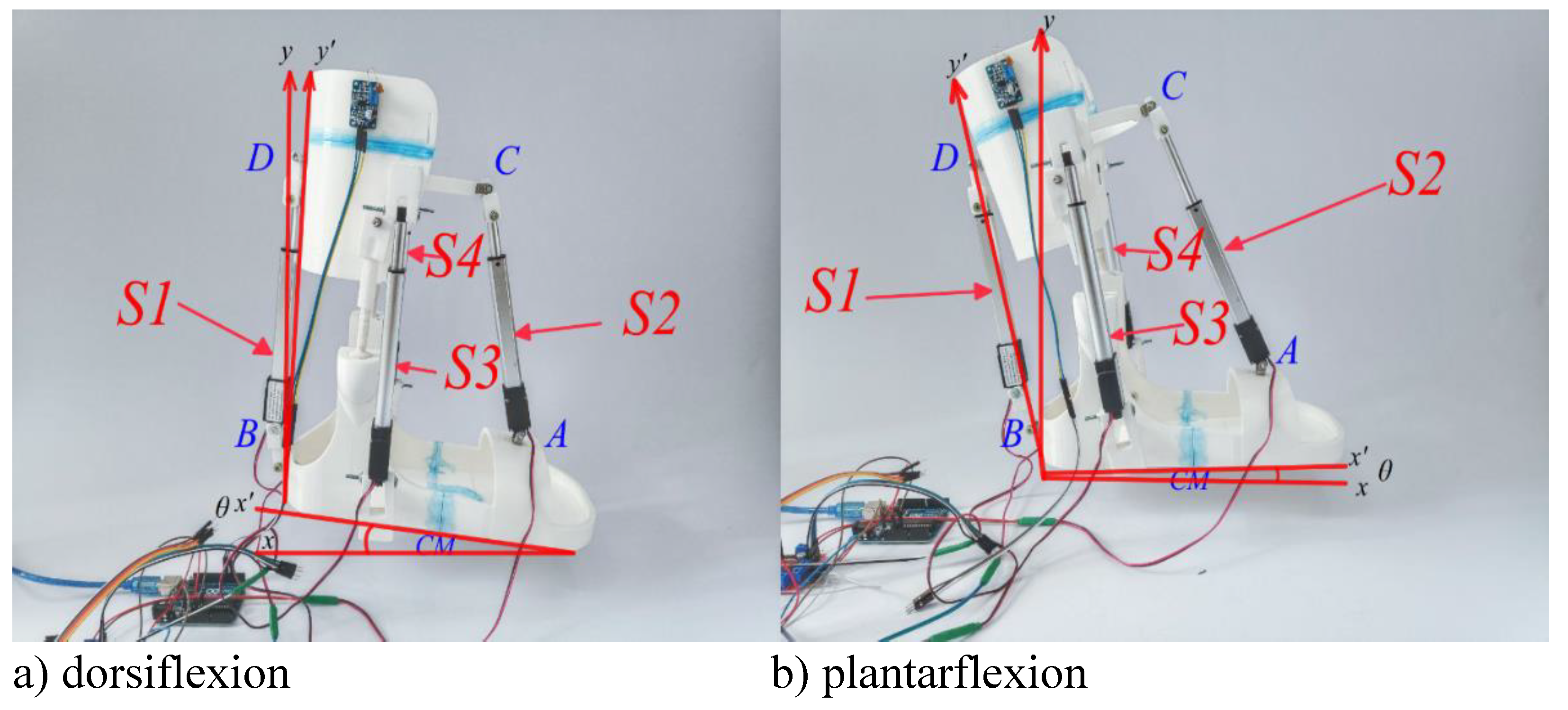
Figure 26.
The results of the Translation motion of the foot platform during dorsiflexion-plantarflexion movements are shown in Figure 25.
Figure 26.
The results of the Translation motion of the foot platform during dorsiflexion-plantarflexion movements are shown in Figure 25.

Figure 27.
The results of the angular displacement of the foot platform during dorsiflexion-plantarflexion movements are shown in Figure 25.
Figure 27.
The results of the angular displacement of the foot platform during dorsiflexion-plantarflexion movements are shown in Figure 25.
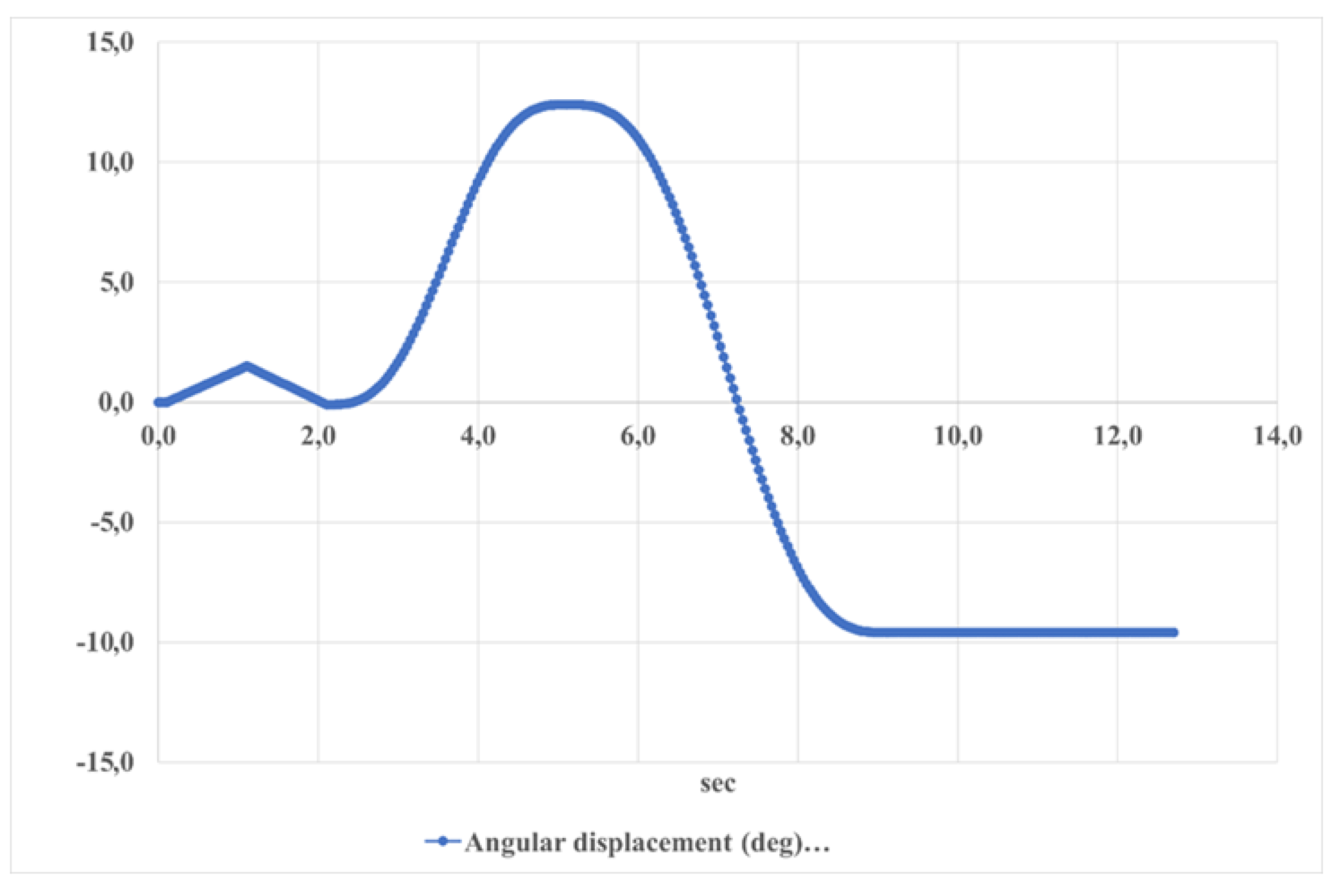
Figure 28.
Angular acceleration of the foot platform during dorsiflexion-plantarflexion movements is shown in Figure 25.
Figure 28.
Angular acceleration of the foot platform during dorsiflexion-plantarflexion movements is shown in Figure 25.
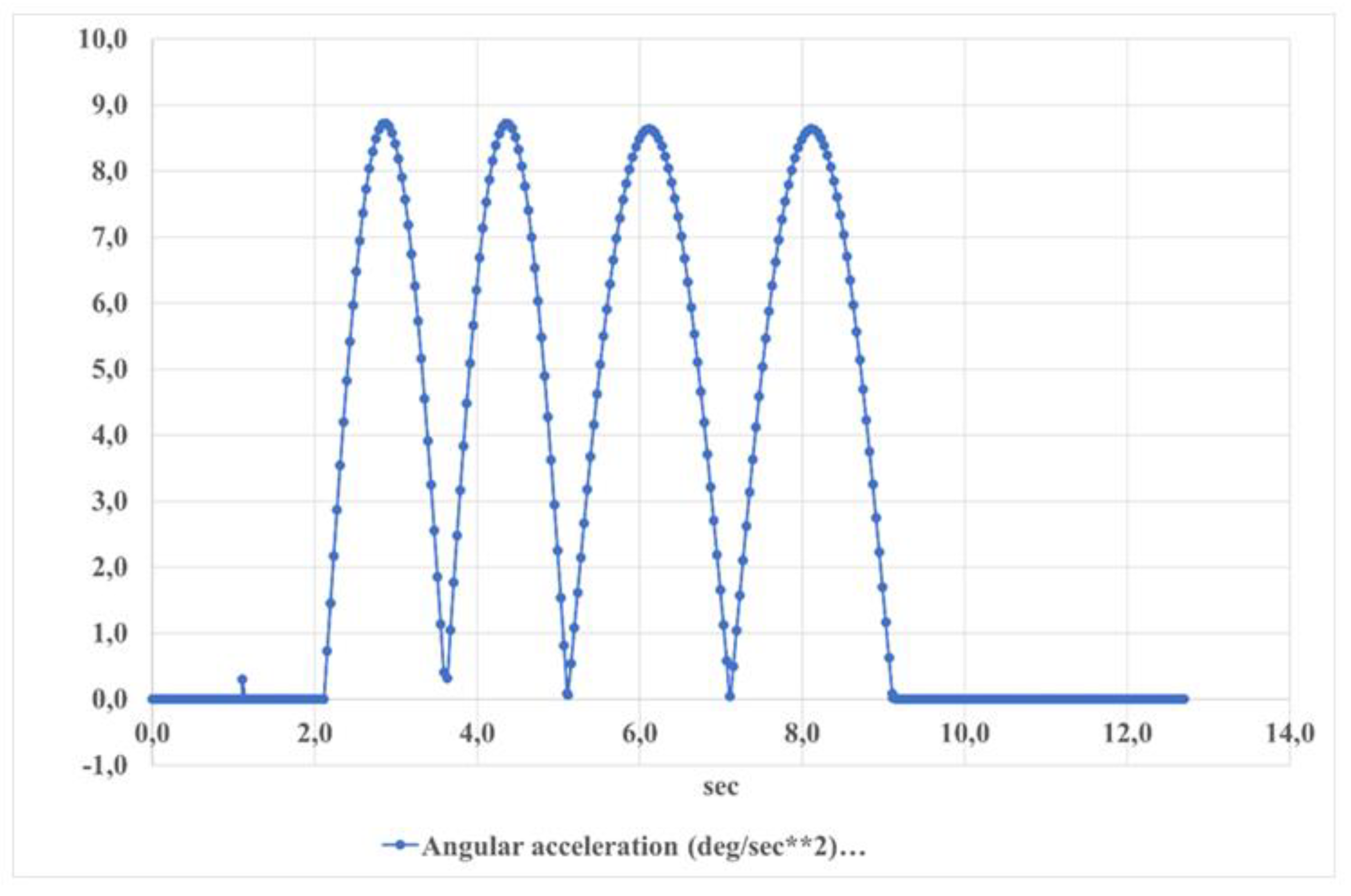
Figure 29.
The speed of the foot platform during dorsiflexion-plantarflexion movements is shown in Figure 25.
Figure 29.
The speed of the foot platform during dorsiflexion-plantarflexion movements is shown in Figure 25.

Figure 30.
Reaction Force of the actuator (S1) when moving the dorsiflexion–plantarflexion is shown in Figure 25.
Figure 30.
Reaction Force of the actuator (S1) when moving the dorsiflexion–plantarflexion is shown in Figure 25.

Figure 31.
Current values in actuators S1 and S2 over time.
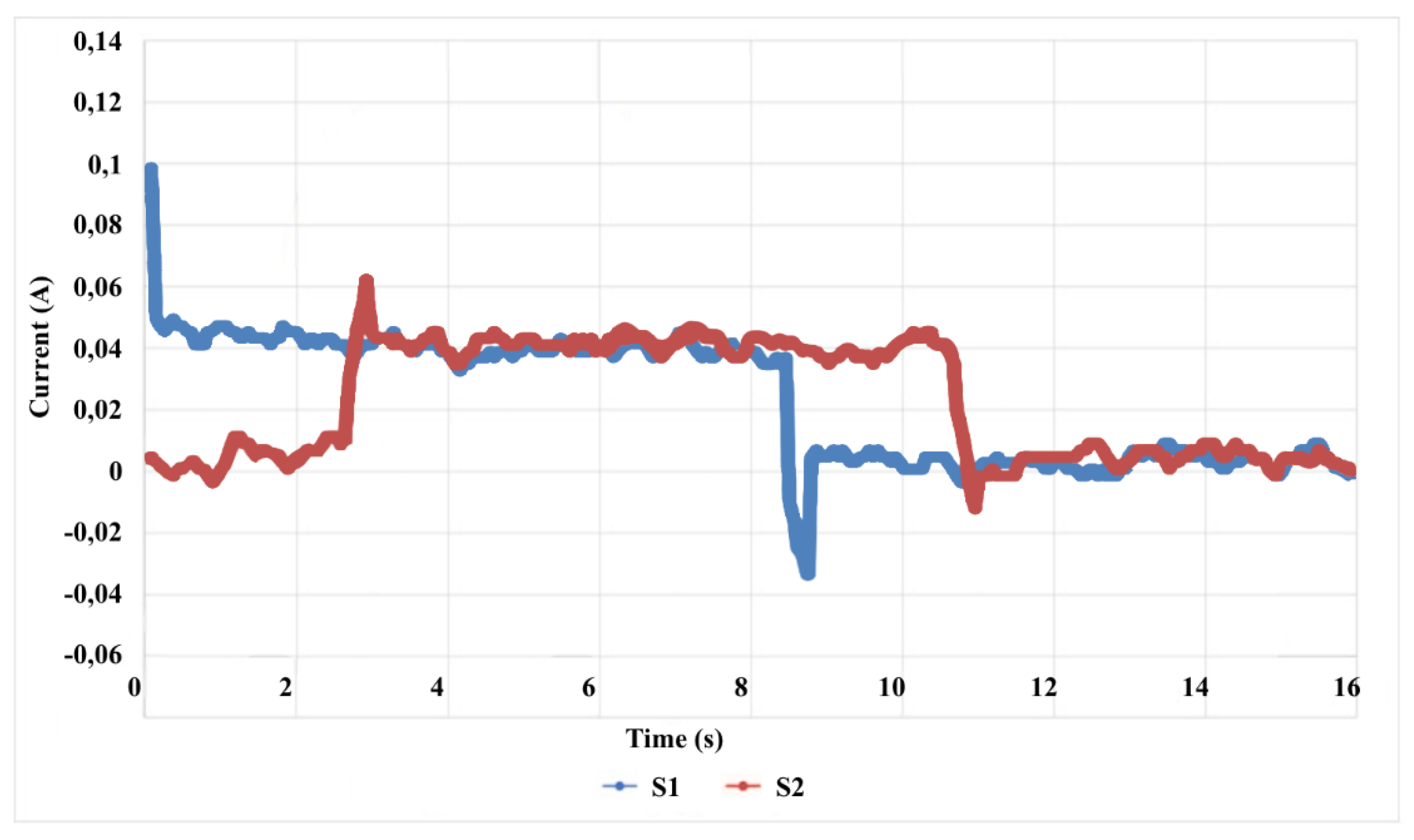

Table 1.
Normal human ROM.
| Motion direction | ROM (degree) |
|---|---|
| Dorsiflexion | 20.3 – 29.8 |
| Plantarflexion | 37.6 – 45.8 |
| Inversion | 14.5 – 22.0 |
| Eversion | 10.0 – 17.0 |
| Abduction | 15.4 – 25.9 |
| Adduction | 22.0 – 36.0 |
Table 2.
Design and operation parameters of a CAD solution in Figure 2.
Table 2.
Design and operation parameters of a CAD solution in Figure 2.
| Size | SP (mm) | FP (mm) | S1 (mm) | S2 (mm) | S3 (mm) | S4 (mm) |
|---|---|---|---|---|---|---|
| 200 | 265 | 243 | 226 | 181 | 93 |
Table 3.
Parameters of the main components of the prototype.
| Component | Commercial name | Voltage | Mass | Max force/torque | Speed |
|---|---|---|---|---|---|
| Arduino board | Mega 2560 23 | 7–12 V | 37 g | — | — |
| Linear actuator | L16-100-63-12-P 19 | 12 V | 74 g | 100 N | 20 mm/s |
| Servomotor | MG996R 20 | 4.8–7.2 V | 55 g | 150 N-cm | 461.5 deg/s |
| IMU | BMI16025 | 3–5 V | 2 g | — | — |
| Force sensor | Sparkfun Resistive sensor | — | 50 g | — | — |
Disclaimer/Publisher’s Note: The statements, opinions and data contained in all publications are solely those of the individual author(s) and contributor(s) and not of MDPI and/or the editor(s). MDPI and/or the editor(s) disclaim responsibility for any injury to people or property resulting from any ideas, methods, instructions or products referred to in the content. |
© 2024 by the authors. Licensee MDPI, Basel, Switzerland. This article is an open access article distributed under the terms and conditions of the Creative Commons Attribution (CC BY) license (http://creativecommons.org/licenses/by/4.0/).
Copyright: This open access article is published under a Creative Commons CC BY 4.0 license, which permit the free download, distribution, and reuse, provided that the author and preprint are cited in any reuse.


