
Submitted:
26 September 2024
Posted:
27 September 2024
You are already at the latest version
Abstract
To explore cast HEAs reinforcement by MC carbides three equimolar CoNiFeCrC alloys without or with Carbon and either hafnium or tantalum were investigated. Their microstructures were specified and tests at 1100°C in oxidation by air and flexural creep tests were carried out. The HEAbase was single–phased. The HEAhfc and HEAtac contained eutectic script HfC and TaC carbides respectively, in the interdendritic spaces. After oxidation for 50h at 1100°C all alloys were covered by a (Cr,Mn)2O3 scale with various proportions in Cr and Mn. HfO2 or CrTaO4 also formed. The subsurface was depleted in Cr and especially in Mn. The HEAbase alloy deformed quickly. The MC carbides greatly improved the creep resistance, and divided deformation by five to ten times.
Keywords:
HEA alloys
; Equimolar CoNiFeMnCr
; HfC
; TaC
; High temperature
; Oxidation
; Creep
1. Introduction
Notably during the last ten years, special attention was given to a new metallurgical principle, High Entropy Alloys (HEA) or Multi-principal Element Alloys (MEAs) [1]. Among the ones which are close to high temperature alloys there are the alloys combining the classical base elements of superalloys – namely nickel, iron and cobalt for strength – and the elements bringing oxidation and corrosion resistance: aluminum and chromium [2]. Some of them, with especially designed chemical compositions, are eutectic high entropy alloys [3,4]. Other elements as Ti [5,6] or Cu, and even Ag and B [7], can be also involved in HEA compositions. One of the most common elements associations met for HEAs is the Co–Ni–Fe–Mn–Cr combination [8,9,10]. This association of five elements has also been found in combination with oxygen to obtain high entropy oxides [11]. Many of the HEAs involving Co, Ni, Fe, Mn and Cr, are designed to respect a molar equivalence for the five elements [12,13,14]. These equimolar CoNiFeMnCr HEAs can be produced using various elaboration ways, including advanced or recent technologies such as single–crystalline structure generation [15] and additive manufacturing [16] for bulk materials, while coatings may be also realized with these particular HEAs [17]. Much attention has been paid to these equimolar CoNiFeMnCr, concerning their thermodynamic proper-ties [18], the study of their mechanical strength and strengthening possibilities [19,20], the diffusion phenomena in this system [21,22], for instance. CoNiFeMnCr alloys in general, and equimolar alloys in particular, are also easily castable. Conventional melting may lead to polycrystalline equi–axed alloys, with interesting oxidation and mechanical behaviors at temperatures not too high. Due to their melting start temperatures which are high enough, they can be considered for uses for hotter conditions of work, but one may worry about their properties. The mechanical ones are especially concerned because of the absence of any phases devoted to intergrains and interdendrites strengthening. For this purpose, primary carbides – and notably MC carbides – have demonstrated favorable influence on the high temperature mechanical properties for chromium–rich nickel–based and cobalt–based model alloys [23] or superalloys [24]. In this role some types of primary MC carbides were recently identified and con-firmed as very useful particles to achieve high level of creep–resistance for Co–based and Ni–based cast alloys [25,26]. Carbon is rather rarely added to HEAs in general, and to CoNiFeMnCr alloys in particular (despite some exceptions [27]). Carbon was seemingly never introduced in HEAs in association with Ta or Hf, elements which are of particular interest in the high temperature MC–strengthening purpose. This is very recently that the {0.25–0.50C, 3.7–7.4Ta or Hf, in wt.%} addition to a conventionally cast CoNiFeMnCr equimolar alloy was tested for the first time. It was found that this al-lowed obtaining successfully, in the interdendritic spaces, the same script–like eutectic TaC [28] or HfC [29] carbides as in the cobalt–chromium or nickel–chromium alloys. In these Co or Ni–based alloys, it was observed that such carbides, with these locations and morphologies, brought remarkable creep strength at high temperature.
Anticipating possible very interesting high temperature mechanical behavior of alloys made of an equimolar CoNiFeMnCr matrix associated to a TaC or HfC interdendritic carbide network, it was wished in this work to explore how such alloys may be-have at high temperature, mechanically and chemically.
2. Materials and Methods
A CoNiFeMnCr equimolar alloy and two of the MC–containing HEAs recently obtained for as–cast microstructure examinations [28,29], were produced, respecting the same chemical compositions and following the same synthesis procedure. This one can be reminded here: melting of pure elements in 300mbars of pure argon using a high frequency induction furnace, solidification of about 40g–weighing ovoid ingots. After classical metallographic preparation their chemical compositions and as–cast microstructures were controlled (scanning electron microscope JEOL JSM6010-LA, Energy Dispersive Spectrometer).
Per alloy, a sample was prepared with the following approximative dimensions: thickness = 3mm, widths or lengths = 10 mm, and with a surface state typical of grinding using #1200 SiC papers (edges and corners smoothed with the same papers). Each sample was tested in oxidation in a muffle resistive furnace (conditions: 50 hours at 1100°C, laboratory air). Tests were followed by classical post–mortem characterization: (1) X–ray diffraction on the oxidized surfaces (Bruker D8 Advance diffractometer, wavelength = 0.15406 nm), (2) embedding in cold resin system, (3) precision cutting of the embedded oxidized sample in two halves, (4) grinding and polishing for obtaining mirror–like state, (5) SEM observation, in the back scattered electrons mode at various magnifications, of the oxides, the subsurfaces affected by oxidation and the bulks affected by the high temperature exposure, (6) EDS spot analysis and concentration pro-files, (7) EDS elemental mapping.
Per alloy again, a sample was cut to obtain a parallelepiped shape (approximative dimensions: thickness = 1.5mm, width or length = 2 and 15 mm). Its surface state was especially prepared by grinding using #1200 SiC papers). It was finally subjected to a centered three–points bending under a load leading to a maximal 10MPa local tensile stress, calculated according to the equation of the elasticity theory. The progress of the displacement, at 1100°C under this constant load, of the central point was monitored using a precision sensor.
3. Results and Discussion
3.1. Chemical Compositions
Preliminarily, the chemical compositions of the three alloys were measured (Table 1). According to the chosen atomic contents in Co, Ni, Fe, Mn and Cr wanted to be all equal to one another, the weight contents in these five elements (the molar weights of which are close to one another) are logically very similar. The Hf or Ta weight contents in the corresponding alloys (respectively “HEAhfc” and “HEAtac”) are a little higher than targeted. Such small overestimation is usual when coarse HfC or TaC are present.
3.2. As–Cast Microstructures
The as–cast “HEAbase” alloy (Figure 1), prepared to serve as reference for identifying the effects of the presence of either HfC or TaC in the behaviors of the other alloys, is obviously single–phased and rather homogeneous chemically. Concerning the second observation, one must mention that Mn segregation seems having occurred during solidification. Such phenomenon was already noticed and studied in CoNiFeMnCr alloys [30]. The Mn–enriched zones allow distinguishing the dendritic structure of this alloy.
The as–cast “HEAhfc” and “HEAtac” alloys (Figure 2 and Figure 3 respectively) are obviously double–phased. Their microstructures are composed of a dendritic matrix and of an interdendritic carbide network made of HfC carbides or TaC carbides respectively. The identification of these carbides were done by carrying out EDS spot analysis on the coarsest carbides found in the metallographic samples. In addition to these script–like eutectic carbides, both alloys also contain some coarse carbides which obviously precipitated prior to the eutectic solidification, even prior to the pre–eutectic development of the dendritic matrix. One can remark that manganese segregation during solidification took place also for these two alloys.
3.3. Post–Mortem Characterization of the Oxidized Samples
Prior to embedding and cross–section preparations, X–ray diffraction was performed on the surfaces of the oxidized samples. The obtained diffractograms were not easy to exploit since the obtained peaks were, for many of them, hard to identify. Nevertheless one can estimate that chromia, {Mn, Cr}–rich oxides and (Co,Ni)Cr2O4 spinel oxides formed over the three alloys during the 50 hours spent at 1100°C (Figure 4 for HEAbase, Figure 5 for HEAhfc and Figure 6 for HEAtac). The additional presence of discrete HfO2 was detected in the case of the HEAhfc alloy. CrTaO4 mixed oxide was evidenced in the case of the HEAtac alloy.
The investigations about the natures of the oxides present were carried out further with the observation of the oxidized stated of the surfaces and subsurfaces in the cross–sectional samples. On low magnification SEM/BSE micrographs (Figure 7) one can see that parts of the external oxide scales were preserved and are available for observation and EDS analysis. These micrographs also allow the examination of the sub-surfaces affected by oxidation: inward progression of oxidation took place for the three alloys, especially for the HEAbase alloy for which local very deep penetration of oxidation may be noticed here and there. Other phenomena also occurred as the inward development of a carbide–free zone from the oxidation front. This is a classical phenomenon for many carbides–containing polycrystalline cast alloys and superalloys [31,32,33]. One can also note the appearance of porosities in the same area, especially for the HEAbase alloy, probably resulting from the Kirdendall effect. This effect was already observed for CoNiFeMnCr alloys during oxidation at temperatures of the 1000°C level [34].
At higher magnification (Figure 8), one can distinguish gray gradation among the {Mn,Cr}–oxides. According to a series of EDS spot analyses, these ones appear being of the M2O3 stoichiometry, with M representing Mn and Cr essentially. The darkest parts of these oxides are richer in chromium than in manganese (about twice more Cr than Mn), and furthermore one can say that the chromia stoichiometry is almost obtained for the darkest oxides located very close to the alloy. The pale parts are richer in Mn than in Cr (about twice more Mn than Cr). The formations of Mn(Cr)2O3 and Cr2O3 were previously reported in the case of the CoNiFeMnCr alloy, but after oxidation at 900°C [34]. In the same work, in which oxidation of this alloy was also studied at 1000 and 1100°C, it appeared that there were more the mixed oxides of Mn and Cr with the (Mn,Cr)3O4 stoechiometry which were seen. Nevertheless, one may insist on the good agreement concerning the simultaneous and important participation of both Cr and Mn in the external oxidation phenomenon.
General chemical information about the results of oxidation on surface and in subsur-face is provided by EDS elemental cartography. Some X–maps are available in Figure 9, Figure 10 and Figure 11, for the HEAbase alloy, the HEAhfc alloy and the HEAtac alloy, respectively. They efficiently illustrate the variations in Cr and Mn contents in the external oxide scales, as described above in the text (all alloys, particularly in Figure 10 and Figure 11) and in the deep oxidation penetration affecting the HEAbase here and there (Figure 9). One can also see the progressive oxidation of the HfC carbides (Figure 10) and of the TaC carbides (Figure 11) in the subsurface (core still carbide and periphery oxidized). In addition the X–maps also allow visualizing the subsurface zone depleted in chromium and in hafnium (more in Figure 9 than in Figure 10 and Figure 11 where these Cr and Mn depletions in subsurface are visually more or less hindered by the presence of coarse Hf or Ta oxides).
To get some quantitative information concerning the chemically–modified zones, a series of EDS spot analyses were performed in the outermost part of each alloy, just be-low the oxidation front. The obtained results led to the values of average and standard deviation for the weight contents presented in Table 2.
One can see that the Cr and Mn contents are significantly lowered, especially in the case of manganese (down to more or less 2 wt.%, against only down to 11.5 wt.% for chromium). This suggests that these contents, notably the Cr one (this is chromia which is really protective against hot oxidation), can be considered as critical values and that general oxidation of the whole alloys was probably imminent when the oxidation test was stopped.
3.4. Three Points Bending Creep Tests
One {1100°C, 10MPa}–creep test was carried out for each alloy. The obtained deformation curves (downward movement of the central point versus time) are presented in Figure 12, Figure 13 and Figure 14 for the HEAbase alloy, the HEAhfc alloy and the HEAtac alloy, respectively. A common point between the three deformation curves is that the primary stage of creep was not finished when temperature reached 1100°C since, at this moment, the deformation rate was still lowering. However, if the transition from the primary stage to the secondary stage was realized after less than 10 hours (followed by a linear deformation) for the HEA alloy, the primary stage took more time for the two carbides–containing alloys: its isothermal duration was about 30 hours for the HEAtac alloy while it seems to be not yet finished after 150 hours for the HEAhfc alloy.
To specify the deformation rate during the secondary creep stage the derived values of central point displacement were calculated and plotted versus time in the same graphs. The deformation rates during the secondary stage are about 10 µm/h for the HEAbase alloy and about 2 µm/h for the HEAtac one. In the case of the HEAhfc alloy, the rate slightly decrease from 2 to less than 1 µm/h over about 150 hours, confirming that the secondary creep stage is not yet completed. With its rather fast deformation rate, the HEAbase sample came in contact with the apparatus base after almost 100 hours (inducing the end of experiment). The two alloys containing MC carbides are obviously much more creep–resistant, demonstrating the strengthening effect of the presence of the eutectic HfC and TaC carbides.
3.5. Comments on the Mechanisms of Oxidation and of Creep Deformation
The oxidation phenomena obviously involved principally chromium and manganese. This is evidenced by, on the first hand the major part of oxide of Mn and Cr in the external and internal corrosion products, and on the second hand by the impoverishment of the subsurface in these two elements, and by the low Cr and Mn contents in the outer part of alloy very close to the oxidation front (particularly Mn). Seemingly, cobalt, nickel and iron only played an anecdotal role in oxidation. Seemingly Ni, Co and Fe were preserved from oxidation thanks to the more oxidable character of Cr, and particularly of Mn. Indeed, at 1100°C, the free enthalpies of formation of the corresponding oxides are ordered as follows (Ellingham’s graph): Mn oxides < Cr oxides < Fe oxides < Co oxides < Ni oxides [35,36]. Some oxides involving Fe, Co or Ni were detected but they were as traces. The other metals which were oxidized were hafnium and tantalum, known as easily oxidable elements.
Obviously, a double diffusion acted for all alloys at 1100°C in air. First, Cr and Mn diffused from the alloy to the oxidation front and formed the external scales. Second, oxygen diffused too, in the opposite direction, with as result an inner oxide growth zone. This was particularly evidenced in some rare locations by grain boundary oxidation (deep oxide penetration in the HEAbase alloy), and by the in situ oxidation of hafnium (in HfO2) or tantalum (in Ta2O5 and CrTaO4 after reaction with Cr2O3). This double simultaneous diffusion in two opposite directions led to an outward oxide thickening and an irregular inward oxidation progression. This second growth mode (inward) al-lowed the formed Mn and Cr oxides immersing some of the HfO2 and CrTaO4 oxides earlier formed internally. Except these formation of HfO2 and CrTaO4 followed by their inclusion in the Mn and Cr oxide inward growth, Hf and Ta did not detrimentally in-fluence the global oxidation behavior of the alloys. The oxidation resistances of the HEAbase and HEAhfc or HEA tac alloys are whatever very perfectible and the degradation by oxidation can shorten life time significantly.
Thus, no evident effect on the oxidation behavior, positive or negative, was noticed for the presence of HfC or TaC carbides. In contrast, a significantly positive influence of these carbides was evidenced here on the creep resistance. Carbides, HfC and TaC are very hard particles, intrinsically very resistant mechanically at all temperatures, including high temperatures. Further, their particular morphology (Chinese script) produces a strong blocking effect between neighbor dendrites and between neighbor grain, which persists a long time at high temperature because of the great resistance of these MC carbides against fragmentation and the consequent loss of carbide continuity. The superiority of the HfC or TaC–strengthened versions of the CoNiFeMnCr HEA base alloy was expected, and it is now verified. In the HEAbase alloy, dislocations freely moved and continuously produced many sliding steps which added up to each other, this resulting in grain–to–grain sliding and then in the macroscopic viscoplastic deformation of the alloy. With the interdendrite and intergrain lockdown due to the HfC or TaC carbides imbricated with matrix, the deformation is much slower. These carbides bring important resistance against mechanical failure.
4. Conclusions
1100°C is a temperature at which the currently best superalloys (the gamma/gamma prime single crystalline ones) start to be not able to be used under mechanical loading because of degradation of their intermetallic reinforcing particles. Inspired by rather recent success of polycrystalline MC–strengthened cobalt–based or nickel–based alloys and superalloys, this work was undertaken to explore the potential of the association of the intrinsically strong matrix composed of the equimolar CoNiFeMnCr alloy and of heat–resistant script–like eutectic MC carbides (HfC or TaC) appeared in the dendrites and grains boundaries during solidification. One obviously obtained here a kind of in situ composites well resistant against creep deformation. If this metallurgical solution may allow long lifetime in the mechanical field, this is not the case concerning in the chemical degradation field. Solutions to improve this point must be identified and tested (as chromium content increase or protective coatings depositions, for instance).
5. Patents
There are no patents resulting from the work reported in this manuscript.
Author Contributions
Conceptualization, P.B.; methodology, P.B.; software, L.A.; validation, P.B. and L.A.; formal analysis, P.B.; investigation, P.B.; resources, L.A.; data curation, P.B. and L.A.; writing—original draft preparation, P.B.; writing—review and editing, P.B.; visualization, P.B.; supervision, P.B.; project administration, P.B.; funding acquisition, Not Applicable. All authors have read and agreed to the published version of the manuscript.
Funding
This research received no external funding.
Institutional Review Board Statement
Not applicable.
Informed Consent Statement
Not applicable.
Data Availability Statement
Not applicable.
Acknowledgments
The authors wish to thank their colleagues for their technical help: Pierre-Jean Panteix (for the exposures of samples in furnace) and Ghouti Medjahdi (who launched the XRD runs).
Conflicts of Interest
The authors declare no conflict of interest.
References
- Wilson, P.; Field, R.; et al. The use of diffusion multiples to examine the compositional dependence of phase stability and hardness of the Co-Cr-Fe-Mn-Ni high entropy alloy system. Intermetallics 2016, 75, 15–24. [Google Scholar] [CrossRef]
- Dabrowa, J.; Kucza, W.; et al. Interdiffusion in the FCC-structured Al-Co-Cr-Fe-Ni high entropy alloys: Experimental studies and numerical simulations. Journal of Alloys and Compounds 2016, 674, 465–462. [Google Scholar] [CrossRef]
- Shafiei, A. Design of eutectic high entropy alloys in Al-Co-Cr-Fe-Ni system. Metals and Materials International 2021, 27, 127–138. [Google Scholar] [CrossRef]
- Shafiei, A. The design of eutectic high entropy alloys in Al-Co-Cr-Fe-Ni system. Condensed Matter 2020, 1–32. [Google Scholar] [CrossRef]
- Stepanov, N.D.; Shaysultanov, D.G.; et al. Structure and high temperature mechanical properties of novel non-equiatomic Fe-(Co, Mn)-Cr-Ni-Al-(Ti) high entropy alloys. Intermetallics 2018, 102, 140–151. [Google Scholar] [CrossRef]
- Zhao, Y.L.; Yang, T.; et al. Development of high-strength Co-free high-entropy alloys hardened by nanosized precipitates. Scripta Materialia 2018, 148, 51–55. [Google Scholar] [CrossRef]
- Nagase, T.; Todai, M.; et al. Liquid phase separation in Ag-Co-Cr-Fe-Mn-Ni, Co Cr-Cu-Fe-Mn-Ni and Co-Cr-Cu-Fe-Mn-Ni-B high entropy alloys for biomedical application. Crystals 2020, 10(6), 527. [Google Scholar] [CrossRef]
- Bracq, G.; Laurent-Brocq, M.; et al. The fcc solid solution stability in the Co-Cr-Fe-Mn-Ni multi-component system. Acta Materialia 2017, 128, 327–336. [Google Scholar] [CrossRef]
- Liu, S. F.; Wu, Y.; et al. Stacking fault energy of face-centered-cubic high entropy alloys. Intermetallics 2018, 93, 269–273. [Google Scholar] [CrossRef]
- Wei, D.; Li, X.; et al. Novel Co-rich high performance twinning-induced plasticity (TWIP) and transformation-induced plas-ticity (TRIP) high-entropy alloys. Scripta Materialia 2019, 165, 39–43. [Google Scholar] [CrossRef]
- Dabrowa, J.; Stygar, M.; et al. Synthesis and microstructure of the (Co,Cr,Fe,Mn,Ni)3O4 high entropy oxide characterized by spinel structure. Materials Letters 2018, 216, 32–36. [Google Scholar] [CrossRef]
- Teramoto, T.; Yamada, K.; et al. Monocrystalline elastic constants and their temperature dependences for equi-atomic Cr-Mn-Fe-Co-Ni high-entropy alloy with the face-centered cubic structure. Journal of Alloys and Compounds 2019, 777, 1313–1318. [Google Scholar] [CrossRef]
- Kauffmann, A.; Stueber, M.; et al. Combinatorial exploration of the high entropy alloy system Co-Cr-Fe-Mn-Ni. Surface and Coatings Technology 2017, 325, 174–180. [Google Scholar] [CrossRef]
- Choi, W.; Jung, S.; et al. Design of new face-centered cubic high entropy alloys by thermodynamic calculation. Metals and Materials International 2017, 23, 839–847. [Google Scholar] [CrossRef]
- Kawamura, M.; Asakura, M.; et al. Plastic deformation of single crystals of the equiatomic Cr-Mn-Fe-Co-Ni high-entropy alloy in tension and compression from 10 K to 1273 K. Acta Materialia 2021, 203, 116454. [Google Scholar] [CrossRef]
- Haase, C.; Tang, F.; et al. Combining thermodynamic modeling and 3D printing of elemental powder blends for high-throughput investigation of high-entropy alloys - Towards rapid alloy screening and design. Materials Science & Engi-neering, A: Structural Materials: Properties, Microstructure and Processing 2017, 688, 180–189. [Google Scholar]
- Ye, Q.; Feng, K.; et al. Microstructure and corrosion properties of CrMnFeCoNi high entropy alloy coating. Applied Surface Science 2017, 396, 1420–1426. [Google Scholar] [CrossRef]
- Song, H.; Ma, Q.; et al. Effects of vacancy on the thermodynamic properties of Co-Cr-Fe-Mn-Ni high-entropy alloys. Journal of Alloys and Compounds 2021, 885, 160944. [Google Scholar] [CrossRef]
- Varvenne, C.; Luque, A.; et al. Theory of strengthening in fcc high entropy alloys. Acta Materialia 2016, 118, 164–176. [Google Scholar] [CrossRef]
- Shafiei, A. Simple approach to model the strength of solid-solution high entropy alloys in Co-Cr-Fe-Mn-Ni system. Condensed Matter 2020, 1–28. [Google Scholar] [CrossRef]
- Kucza, W.; Dabrowa, J.; et al. Studies of "sluggish diffusion" effect in Co-Cr-Fe-Mn-Ni, Co-Cr-Fe-Ni and Co-Fe-Mn-Ni high entropy alloys; determination of tracer diffusivities by combinatorial approach. Journal of Alloys and Compounds 2018, 731, 920–928. [Google Scholar] [CrossRef]
- Chen, W.; Zhang, L. High-throughput determination of interdiffusion coefficients for Co-Cr-Fe-Mn-Ni high-entropy alloys. Journal of Phase Equilibria and Diffusion 2017, 38(4), 457–465. [Google Scholar] [CrossRef]
- Berthod, P.; Conrath, E. Mechanical and chemical properties at high temperature of {M-25Cr}-based alloys containing hafnium carbides (M=Co, Ni or Fe): creep behavior and oxidation at 1200°C. Journal of Material Science and Technology Research 2014, 1, 7–14. [Google Scholar] [CrossRef]
- Michon, S.; Aranda, L.; et al. High temperature evolution of the microstructure of a cast cobalt base superalloy. Consequences on its thermomechanical properties. La Revue de Métallurgie-CIT/Science et Génie des Matériaux 2004, 651–662. [Google Scholar] [CrossRef]
- Berthod, P.; Tlili, S. Creep and oxidation behaviors of 25 wt. % Cr–containing nickel-based alloys reinforced by ZrC carbides. Crystals 2022, 12, 416. [Google Scholar]
- Berthod, P.; Conrath, E. Creep and oxidation kinetics at 1100 °C of nickel-base alloys reinforced by hafnium carbides. Mate-rials and Design 2016, 104, 27–36. [Google Scholar] [CrossRef]
- Stepanov, N.D.; Yurchenko, N.Y.; et al. Effect of carbon content and annealing on structure and hardness of the CoCrFeNiMn-based high entropy alloys. Journal of Alloys and Compounds 2016, 687, 59–71. [Google Scholar] [CrossRef]
- Berthod, P. As-Cast microstructures of high entropy alloys designed to be TaC-strengthened. Journal of Metallic Material Research 2022, 5(2), 1–10. [Google Scholar] [CrossRef]
- Berthod, P. As–cast microstructures of HEA designed to be strengthened by HfC. Journal of Engineering Sciences and Innovation 2022, 7, 305–314. Available online: https://jesi.astr.ro/wp-content/uploads/2022/10/3_Patrice-Berthod. [CrossRef]
- Ferrari, A.; Koermann, F. Surface segregation in Cr-Mn-Fe-Co-Ni high entropy alloys. Applied Surface Science 2020, 533, 147471. [Google Scholar] [CrossRef]
- Berthod, P. Influence of chromium carbides on the high temperature oxidation behavior and on chromium diffusion in nickel-base alloys. Oxidation of Metals 2007, 68, 77–96. [Google Scholar] [CrossRef]
- Berthod, P.; Hamini, Y.; et al. Influence of tantalum on the rates of high temperature oxidation and chromia volatilization for cast (Fe and/or Ni)-30Cr-0.4C alloys. Materials Science Forum 2008, 595-598, 861–870. [Google Scholar] [CrossRef]
- Conrath, E.; Berthod, P. Kinetics of high temperature oxidation of chromium rich HfC reinforced cobalt based alloys. Corro-sion Engineering, Science and Technology 2014, 49, 45–54. [Google Scholar] [CrossRef]
- Kim, Y.K.; Joo, Y.A.; et al. High temperature oxidation behavior of Cr-Mn-Fe-Co-Ni high entropy alloy. Intermetallics 2018, 98, 45–53. [Google Scholar] [CrossRef]
- Sabat, K.C.; Rajput, P.; Paramguru, R.K. , Bhoi, B. ; Mishra, B.K. Reduction of Oxide Minerals by Hydrogen Plasma: An Overview. Plasma Chem Plasma Process 2014, 34, 1–23. [Google Scholar]
- Available online: https://commons.wikimedia.org/wiki/File:Ellingham_Richardson-diagram_english.svg.
Figure 1.
The microstructure of the as–cast HEAbase alloy (SEM/BSE image with EDS spectrum of the area, left) and the elemental distribution showed by EDS X-maps (right).
Figure 1.
The microstructure of the as–cast HEAbase alloy (SEM/BSE image with EDS spectrum of the area, left) and the elemental distribution showed by EDS X-maps (right).
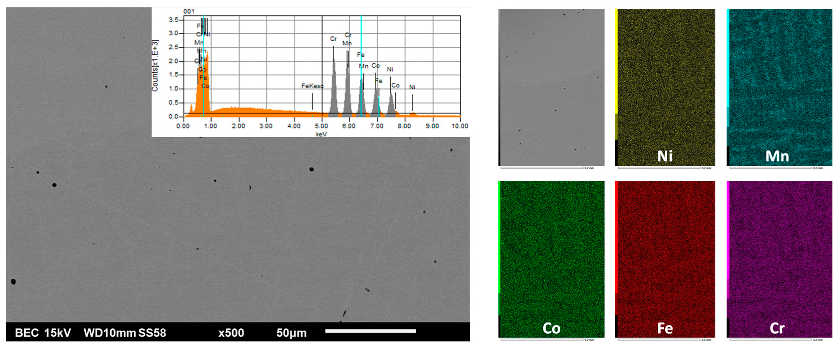
Figure 2.
The microstructure of the as–cast HEAhfc alloy (SEM/BSE image with EDS spectrum of the area, left) and the elemental distribution showed by EDS X-maps (right).
Figure 2.
The microstructure of the as–cast HEAhfc alloy (SEM/BSE image with EDS spectrum of the area, left) and the elemental distribution showed by EDS X-maps (right).
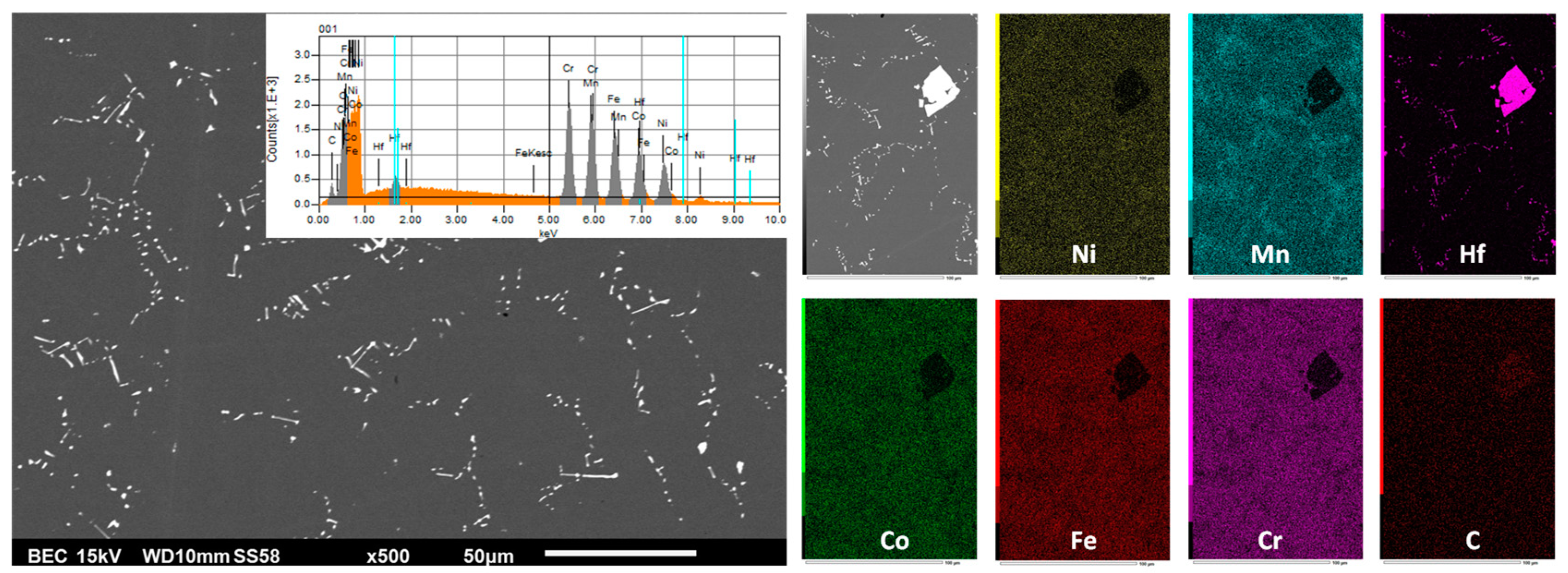
Figure 3.
The microstructure of the as–cast HEAtac alloy (SEM/BSE image with EDS spectrum of the area, left) and the elemental distribution showed by EDS X-maps (right).
Figure 3.
The microstructure of the as–cast HEAtac alloy (SEM/BSE image with EDS spectrum of the area, left) and the elemental distribution showed by EDS X-maps (right).

Figure 4.
Diffractogram acquired of one of the oxidized surfaces of the HEAbase alloy.
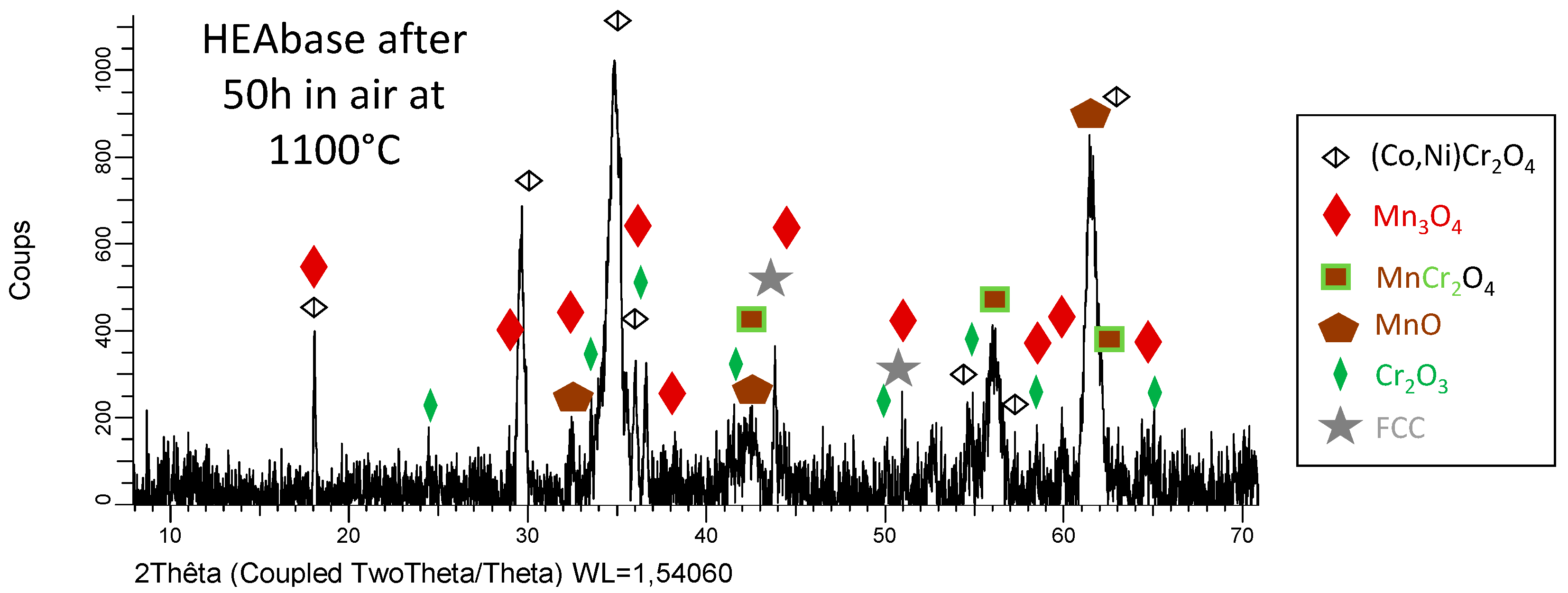
Figure 5.
Diffractogram acquired of one of the oxidized surfaces of the HEAhfc alloy.
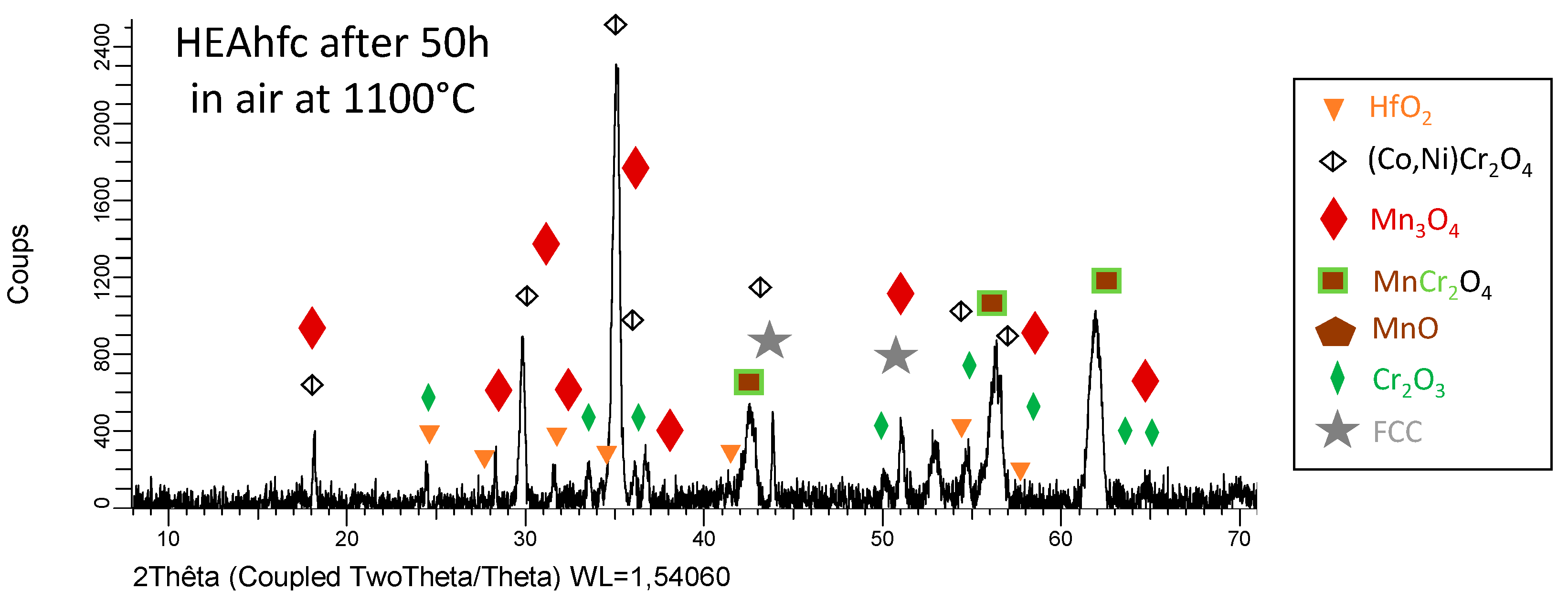
Figure 6.
Diffractogram acquired of one of the oxidized surfaces of the HEAtac alloy.
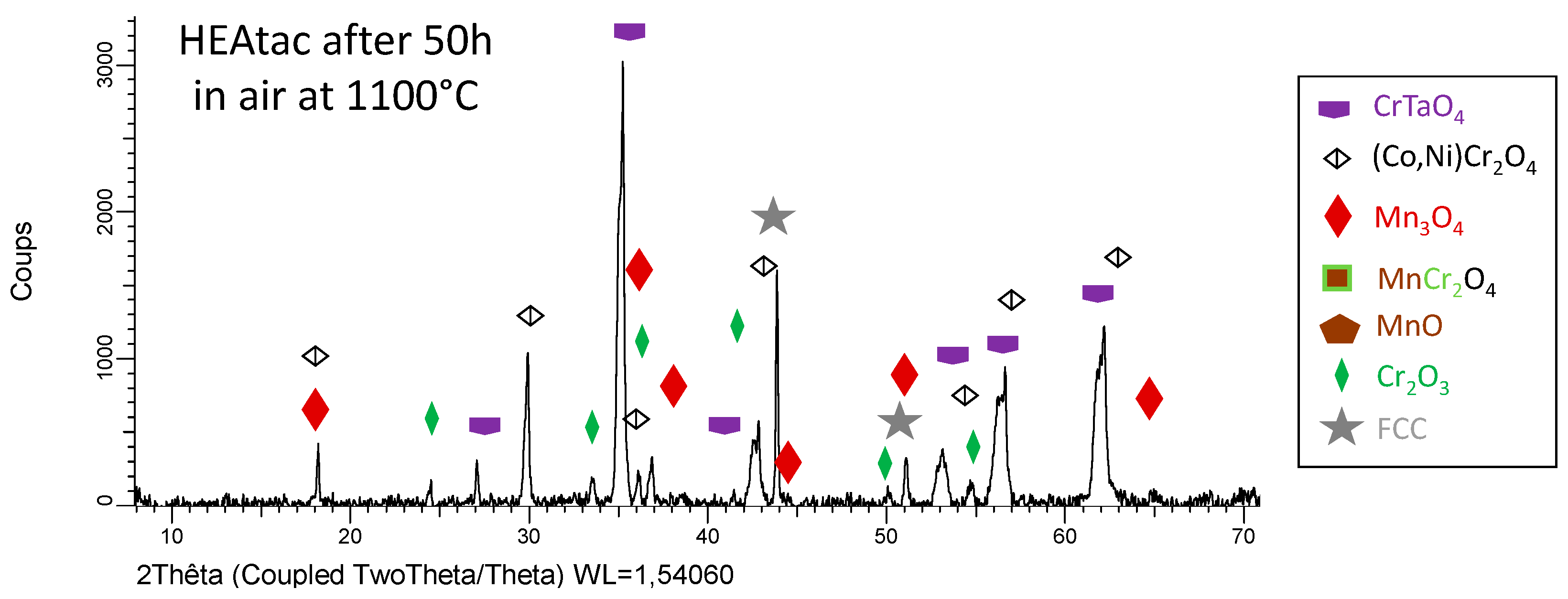
Figure 7.
Low magnification SEM/BSE micrographs giving general views of the oxidized surfaces, subsurfaces and bulks.
Figure 7.
Low magnification SEM/BSE micrographs giving general views of the oxidized surfaces, subsurfaces and bulks.
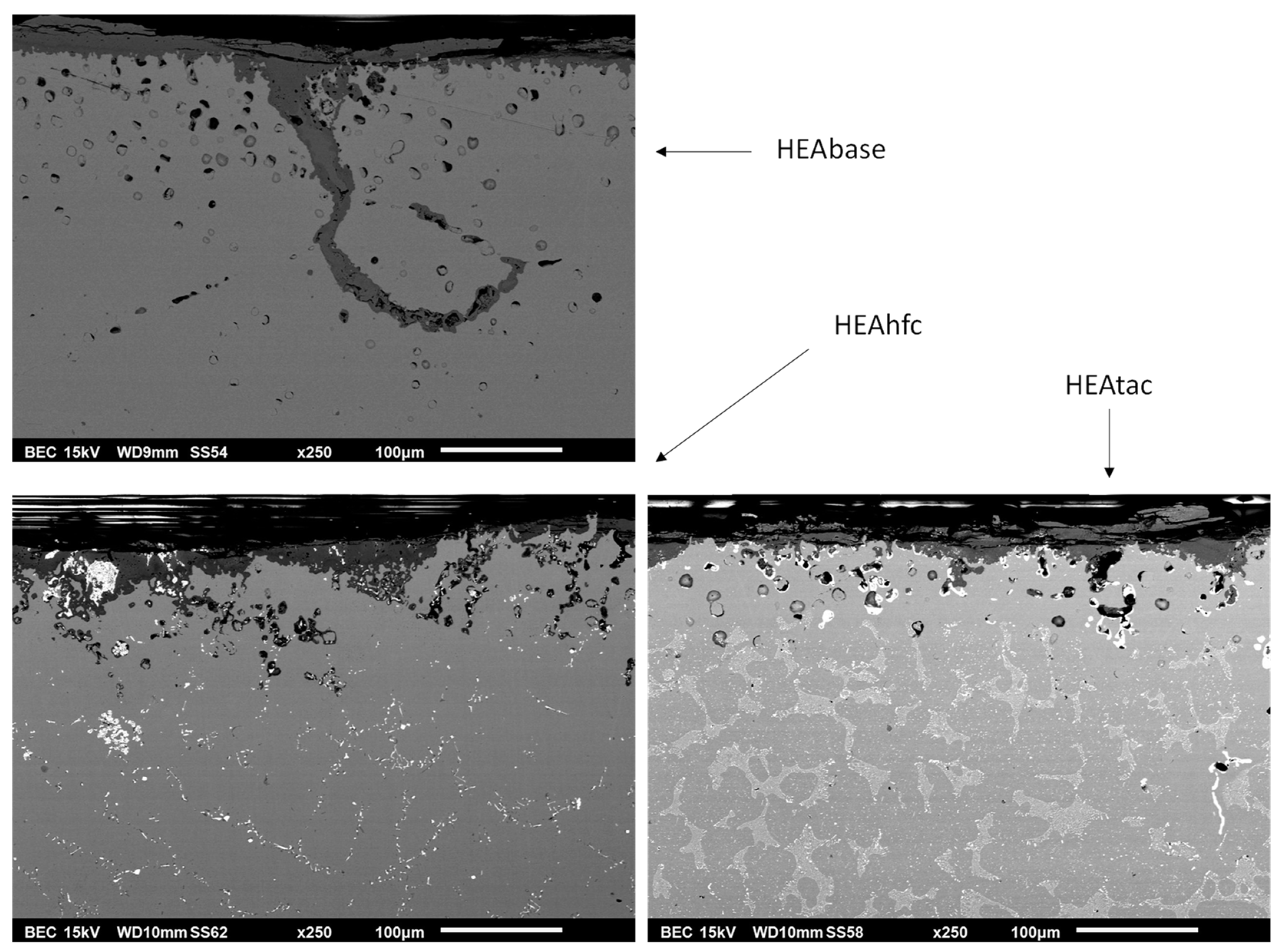
Figure 8.
High magnification SEM/BSE micrographs giving detailed views of the oxidized surfaces and subsurfaces, with the results of EDS spot analysis identification of the oxides.
Figure 8.
High magnification SEM/BSE micrographs giving detailed views of the oxidized surfaces and subsurfaces, with the results of EDS spot analysis identification of the oxides.
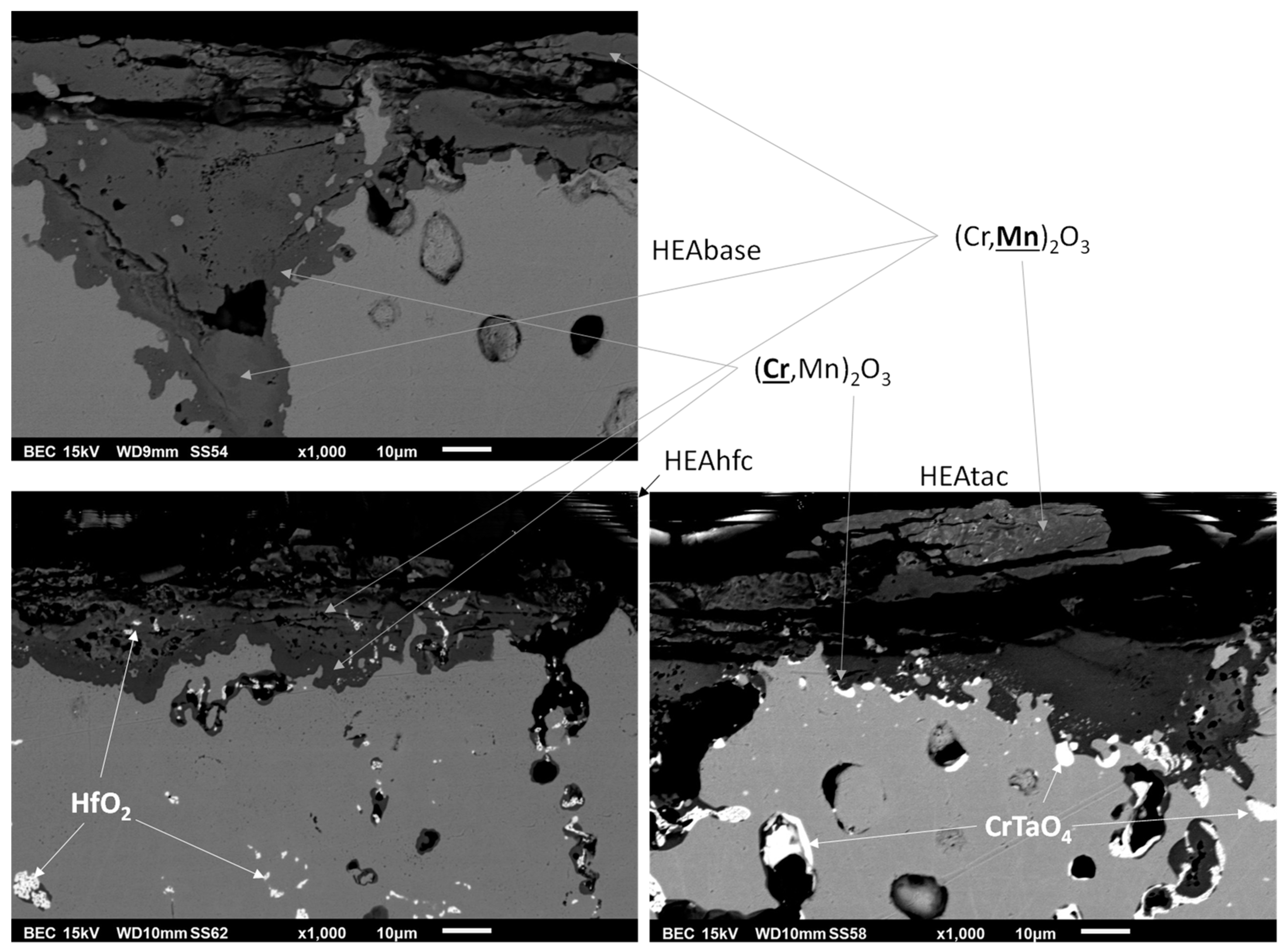
Figure 9.
Elemental EDS cards of the oxidized surface and subsurface in the case of HEAbase.
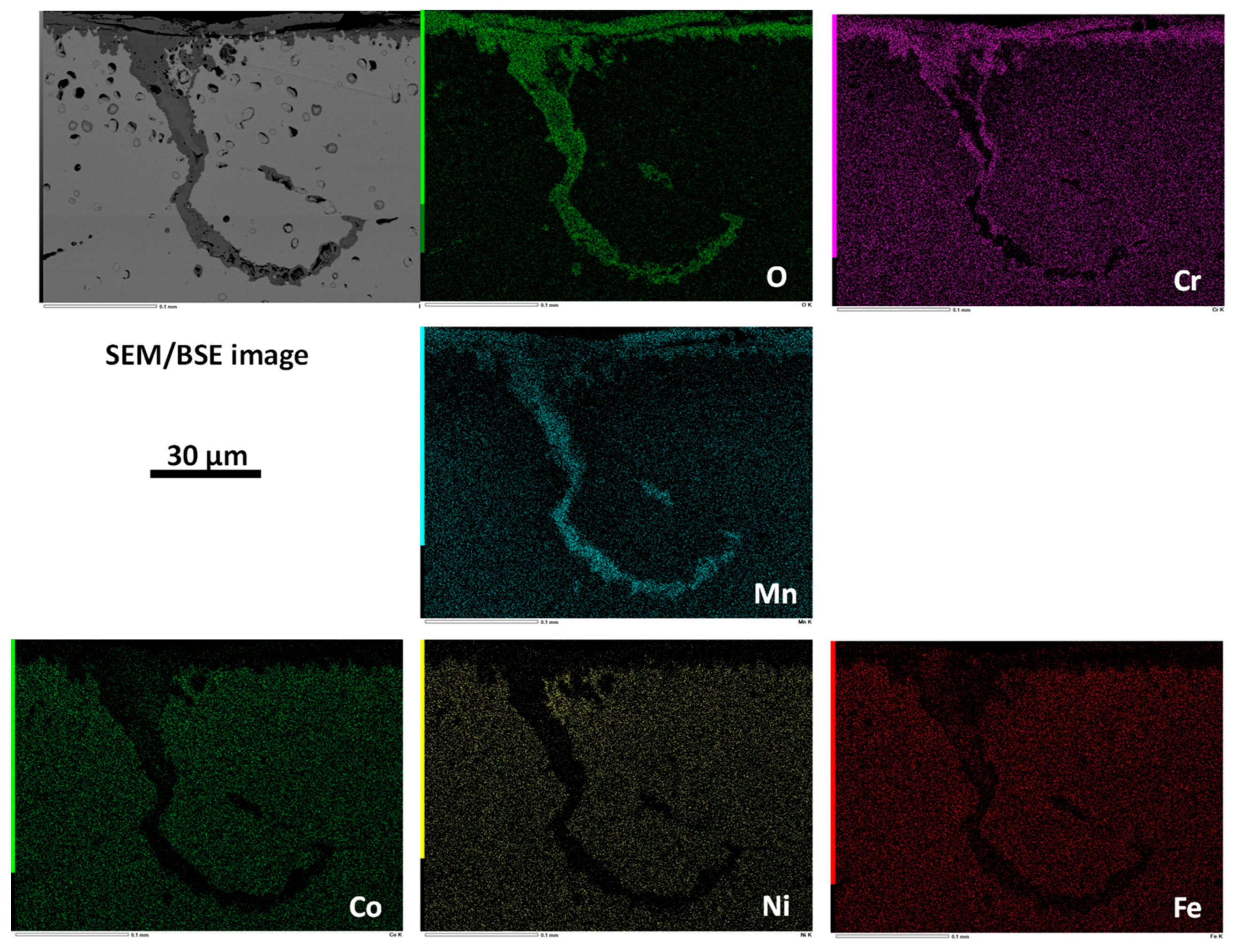
Figure 10.
Elemental EDS cards of the oxidized surface and subsurface in the case of HEAhfc.
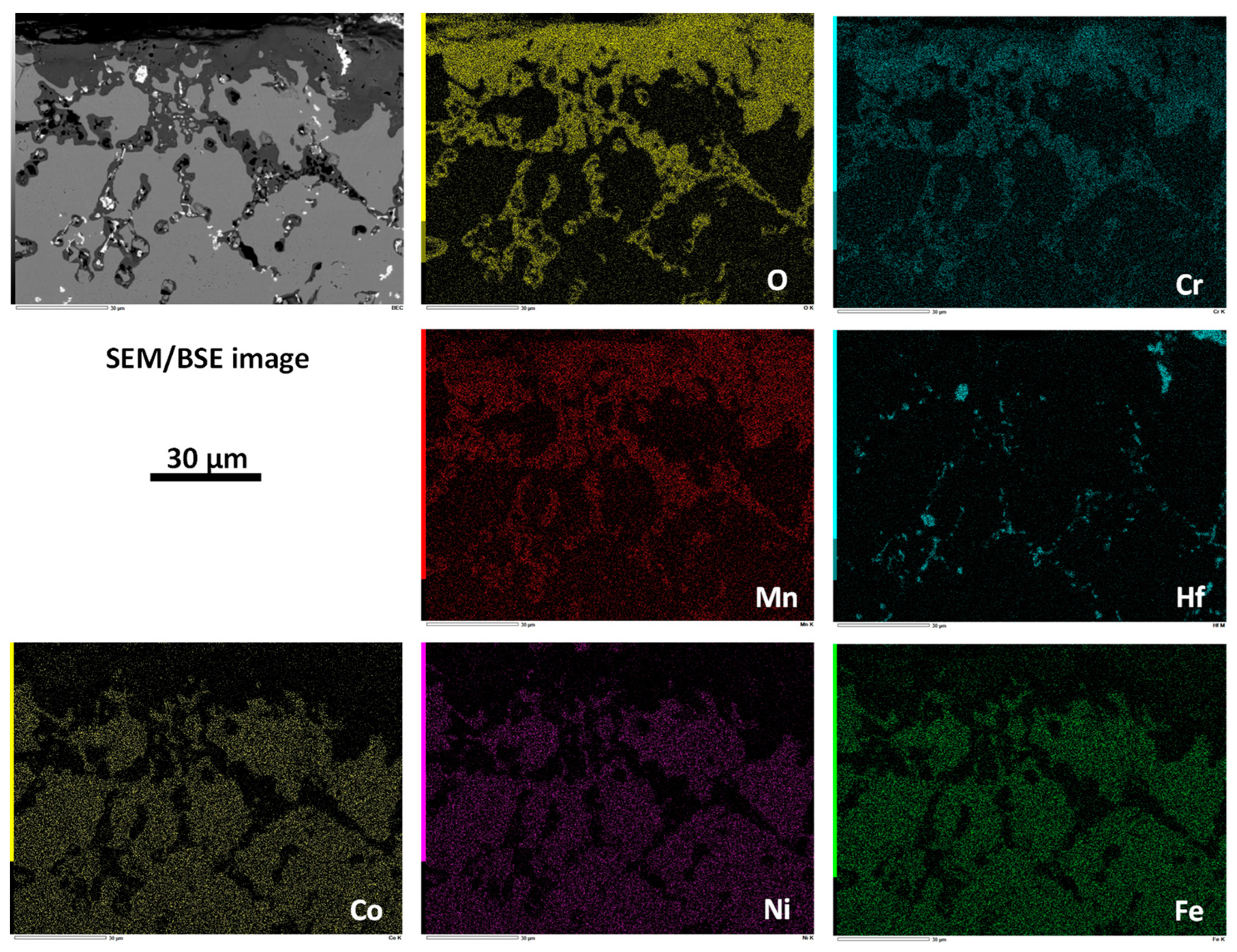
Figure 11.
Elemental EDS cards of the oxidized surface and subsurface in the case of HEAtac.
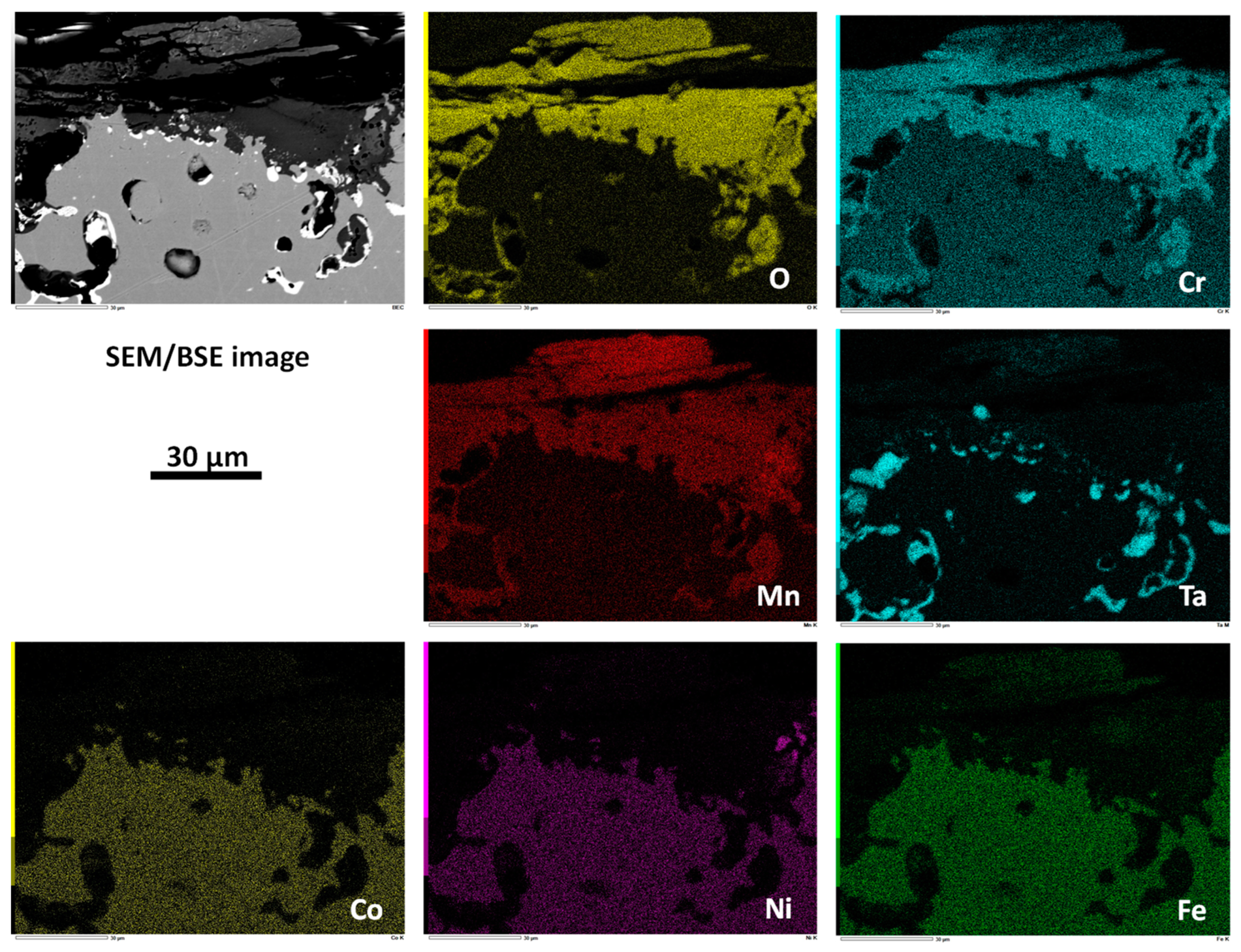
Figure 12.
Deformation curve of the HEAbase alloy, superposed with the corresponding deformation rate evolution.
Figure 12.
Deformation curve of the HEAbase alloy, superposed with the corresponding deformation rate evolution.
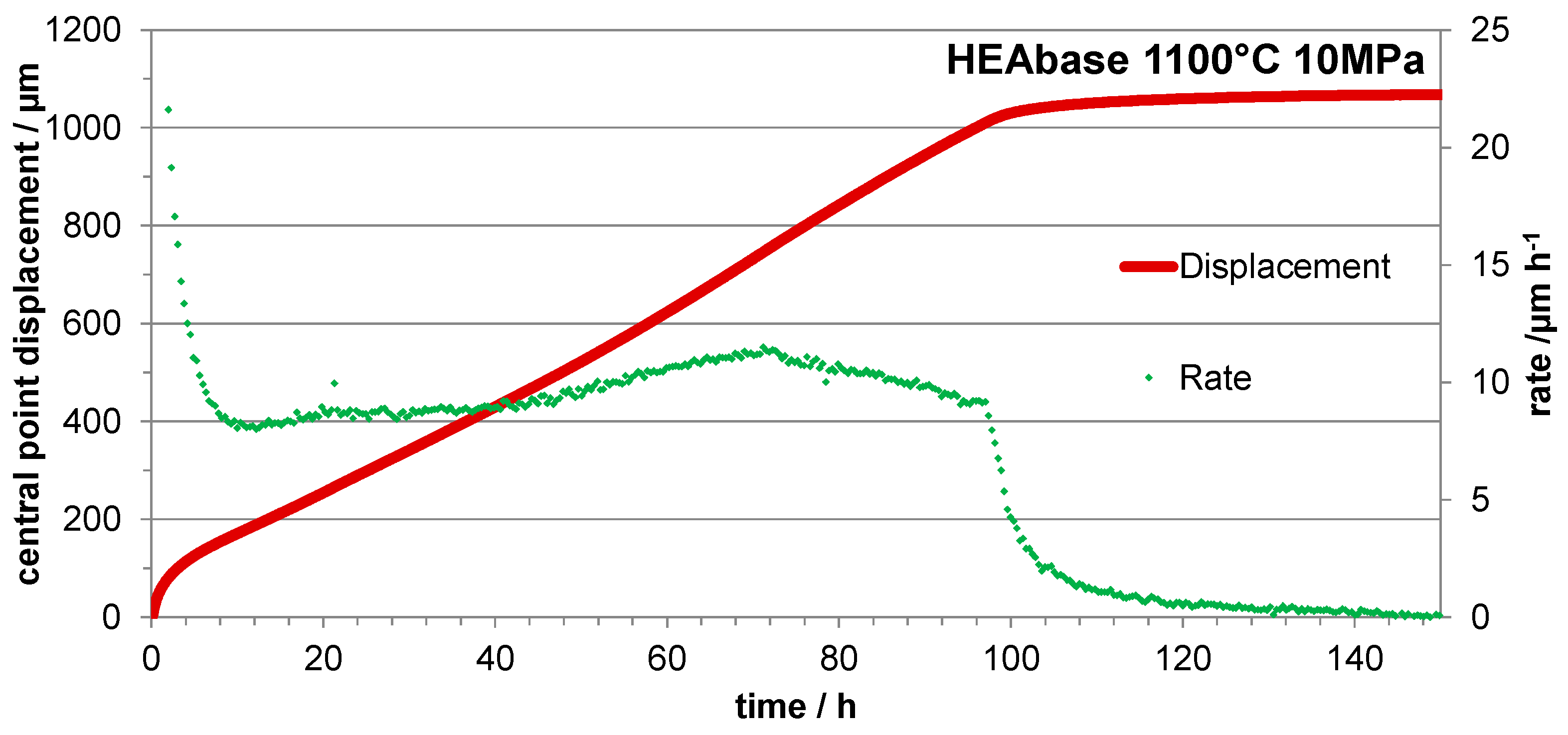
Figure 13.
Deformation curve of the HEAhfc alloy, superposed with the corresponding deformation rate evolution.
Figure 13.
Deformation curve of the HEAhfc alloy, superposed with the corresponding deformation rate evolution.
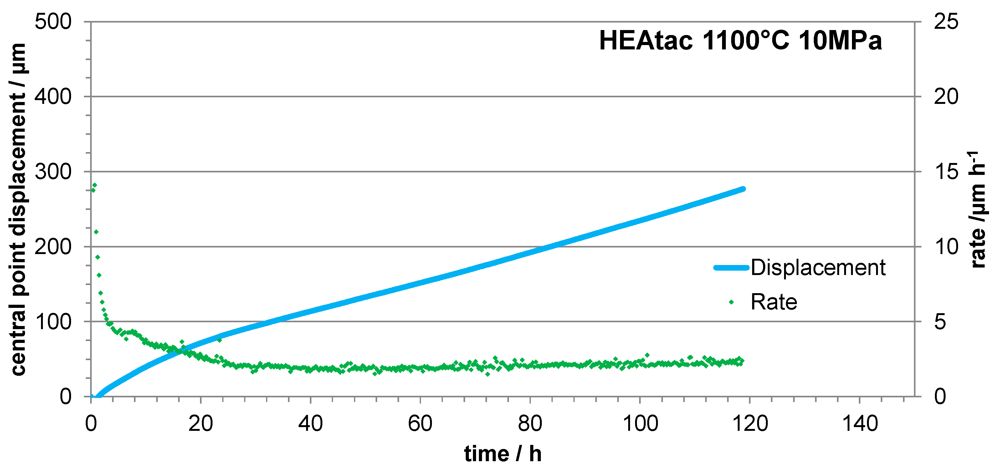
Figure 14.
Deformation curve of the HEAtac alloy, superposed with the corresponding deformation rate evolution.
Figure 14.
Deformation curve of the HEAtac alloy, superposed with the corresponding deformation rate evolution.
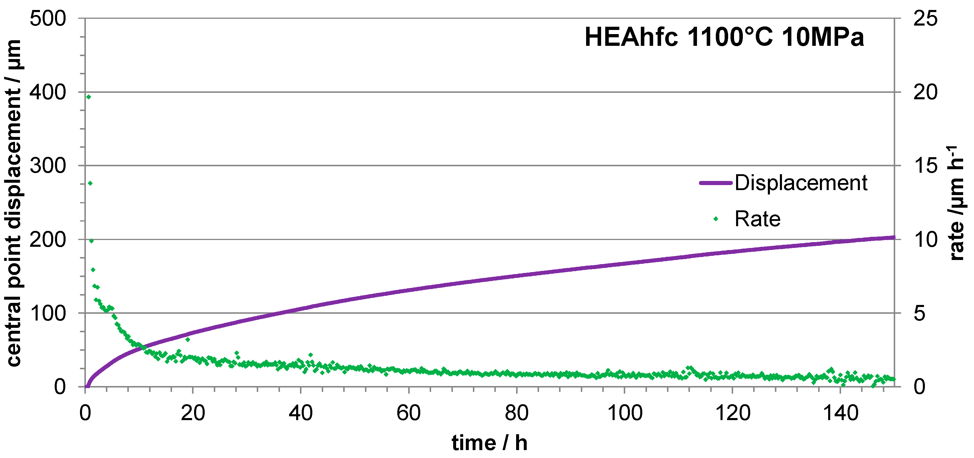

Table 1.
Designation and controlled chemical compositions of the three alloys (from five 250 full frame EDS analyses per alloy); weight and atomic contents in all elements except carbon (for C: 0.25wt.% and 1.2at.% for both HEAhfc and HEAtac).
Table 1.
Designation and controlled chemical compositions of the three alloys (from five 250 full frame EDS analyses per alloy); weight and atomic contents in all elements except carbon (for C: 0.25wt.% and 1.2at.% for both HEAhfc and HEAtac).
| Weight and atomic contents | Cr | Mn | Fe | Co | Ni | Hf or Ta | |
|---|---|---|---|---|---|---|---|
| HEAbase | wt.% | 19.8 | 19.5 | 19.5 | 19.8 | 21.4 | / |
| at.% | 20.1 | 20.2 | 19.9 | 19.1 | 20.7 | / | |
| HEAhfc | wt.% | 19.3 | 18.2 | 18.4 | 19.9 | 20.2 | 4.0 |
| at.% | 19.9 | 19.1 | 19.0 | 19.5 | 19.9 | 1.3 | |
| HEAtac | wt.% | 19.2 | 18.3 | 18.6 | 19.3 | 20.1 | 4.5 |
| at.% | 19.9 | 19.3 | 19.3 | 19.0 | 19.9 | 1.4 |
Table 2.
Chemical compositions in alloy very close to the interface with the external oxide scale (from five spot EDS analyses per alloy).
Table 2.
Chemical compositions in alloy very close to the interface with the external oxide scale (from five spot EDS analyses per alloy).
| Extreme surface (contents in wt.%) |
Cr | Mn | Fe | Co | Ni | Hf or Ta | |
|---|---|---|---|---|---|---|---|
| HEAbase | Average | 12.1 | 1.9 | 29.9 | 27.7 | 28.3 | / |
| Std dev. | 0.5 | 0.1 | 0.3 | 0.3 | 0.3 | / | |
| HEAhfc | Average | 11.0 | 2.5 | 27.8 | 28.9 | 29.9 | 0 |
| Std dev. | 1.0 | 0.5 | 0.5 | 1.0 | 1.0 | 0 | |
| HEAtac | Average | 11.7 | 1.6 | 29.4 | 27.0 | 30.0 | 0.3 |
| Std dev. | 1.2 | 0.1 | 0.8 | 0.2 | 0.9 | 0.4 |
Disclaimer/Publisher’s Note: The statements, opinions and data contained in all publications are solely those of the individual author(s) and contributor(s) and not of MDPI and/or the editor(s). MDPI and/or the editor(s) disclaim responsibility for any injury to people or property resulting from any ideas, methods, instructions or products referred to in the content. |
© 2024 by the authors. Licensee MDPI, Basel, Switzerland. This article is an open access article distributed under the terms and conditions of the Creative Commons Attribution (CC BY) license (http://creativecommons.org/licenses/by/4.0/).
Copyright: This open access article is published under a Creative Commons CC BY 4.0 license, which permit the free download, distribution, and reuse, provided that the author and preprint are cited in any reuse.


