
Submitted:
23 September 2024
Posted:
23 September 2024
You are already at the latest version
Abstract
A broadband 28 nm complementary metal-oxide-semiconductor (CMOS) power amplifier was implemented using a distributed amplification design. To develop a model library for high-frequency design, various test patterns for active and passive elements were fabricated and compared through measurements. As a result, an n-channel field-effect transistor (NFET) with a symmetrical layout was adopted as the active device, and a co-planar waveguide (CPW) structure with floating first and second metal layers at the bottom was selected as the transmission line for the passive element. These choices demonstrated superior radio frequency (RF) characteristics at high frequencies compared to other device candidates. Furthermore, to address the low breakdown voltage of CMOS, a triple-stacked FET structure was designed as the gain cell of the distributed power amplifier (DPA). The fabricated DPA showed a maximum small-signal gain of 22 dB and a minimum of 10 dB from DC to 56 GHz, with a maximum saturated Pout of 20 dBm and a minimum of 13 dBm from 1 to 39 GHz. Notably, these results were achieved on the first attempt by designing solely based on measurement data from the test patterns.
Keywords:
28 nm CMOS
; broadband
; distributed power amplifier
; stacked FET
; power combining
1. Introduction
The advent of fifth-generation (5G) communications has driven the development of transceiver modules that operate at higher frequencies for use in base stations and wireless communication terminals. 5G communications can be broadly categorized into two types: sub-6 GHz, centered around the 3.5 GHz band, and millimeter-wave communications, focused on the 28 GHz and 39 GHz bands. Recently, there has been a rise in the allocation of low-cost private 5G spectrum, designated for companies to build their own private 5G networks, as opposed to the high-priced 5G spectrum auctioned by governments to national operators. Table 1 illustrates the current utilization of 5G spectrum in major countries globally [1]. Millimeter-wave communications are expected to become increasingly common, not only in the United States but also in other countries, due to their ability to transmit large amounts of data at ultra-high speeds, with communication bandwidth nearly 10 times greater than that of sub-6 GHz. As a result, research on transceiver modules and circuits for 5G millimeter-wave communication is actively being conducted [2,3,4].
In addition to the commercialization of 5G communications, the standardization for sixth-generation (6G) communications is also underway. The frequencies currently under consideration for 6G span the 4 GHz, 7 GHz, and 15 GHz ranges [5]. Given the recent proliferation of existing WiFi and ultra-wideband (UWB) frequencies for various applications, future communication services are expected to cover a wide range of frequencies, from 1 to 40 GHz.
The objective of this research is to develop a broadband transceiver capable of operating across a wide range of frequencies, including both current and future commercially available bands, and to implement a power amplifier, a key component for achieving high-frequency performance. First, various test patterns are fabricated and measured before the circuit design to identify the optimal active and passive components essential for high-frequency circuit design. Next, a distributed amplifier (DA) is introduced to achieve broadband gain and output power (Pout) from 1 to 40 GHz. To enhance Pout, a triple-stacked structure is incorporated to increase the voltage swing.
This paper is organized as follows: Chapter 2 presents and analyzes the measurement results of the test patterns used to select the optimal active and passive elements in a commercial 28nm radio frequency (RF) complementary metal-oxide-semiconductor (CMOS) process. Chapter 3 describes the design and measurement of a broadband power amplifier based on distributed amplifier design theory, followed by conclusions in Chapter 4.
2. Test-Pattern Measurements for the Distributed Power Amplifier Design
2.1. Active Devices
The circuits developed in this study are designed to operate up to the millimeter-wave frequency band. Since the wavelength in this band is less than one millimeter, circuits for millimeter-wave signals require a different approach than conventional electronic circuits. It is necessary to consider parasitic capacitance and parasitic inductance, which were previously excluded from analysis, within the context of millimeter-wave frequencies. These parasitic components must be included in the equivalent model, as they will affect the high-frequency characteristics of the transistor. The size and layout of the transistor can also influence the magnitude of the parasitics, which can significantly alter high-frequency performance. Therefore, selecting a transistor prototype with optimal high-frequency characteristics is crucial before designing a millimeter-wave communication circuit.
In previous studies [6,7], the RF performance of various transistor layout structures was compared. However, there is a need to validate transistor layout structures for power amplifier designs in CMOS processes with a different back end of line (BEOL) than at that time. This study compares the high-frequency characteristics of transistors based on their size and layout structure. S-parameter measurements are conducted using a vector network analyzer (VNA) to investigate these characteristics, and transistors are designed and fabricated using a commercial 28 nm CMOS process.
Figure 2.
RF transistor layout of (a) symmetry-typed and (b) ring-typed structure (both are 2 × 64 μm LVT NFET_RF devices).
Figure 2.
RF transistor layout of (a) symmetry-typed and (b) ring-typed structure (both are 2 × 64 μm LVT NFET_RF devices).
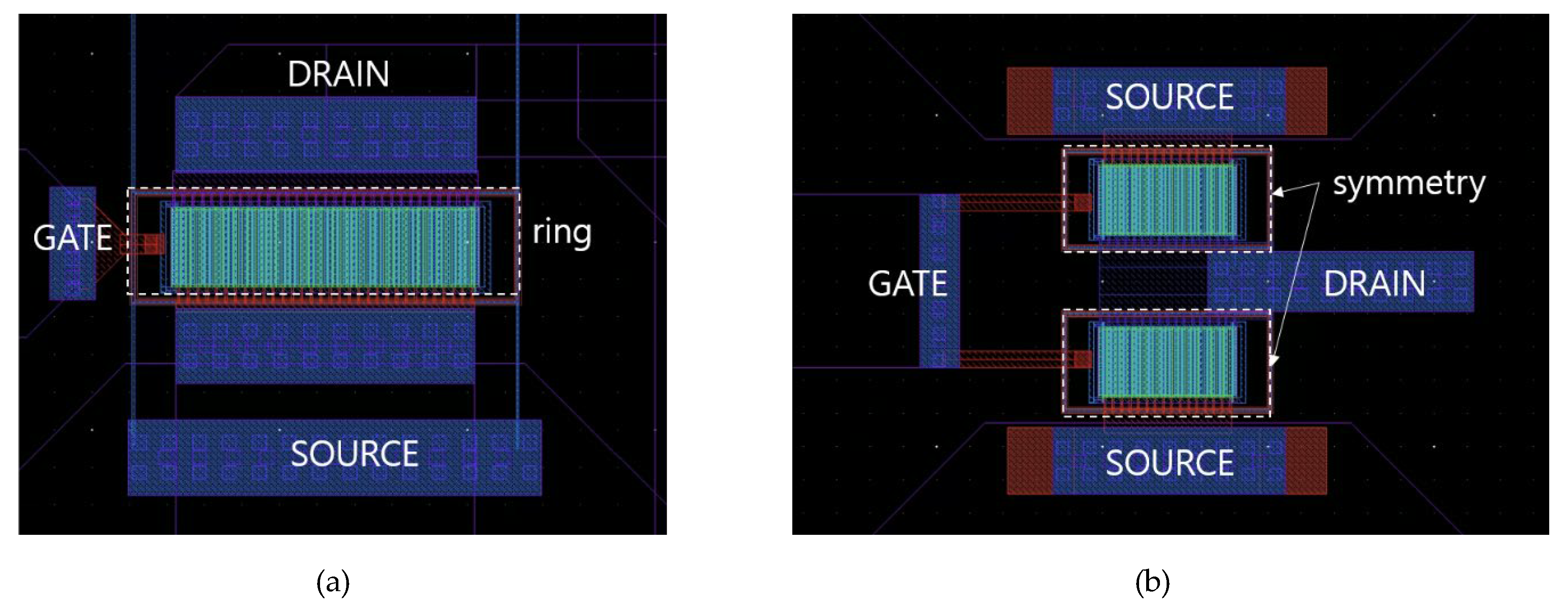
For this circuit design, we developed test patterns for key passive and active devices during the last multi-project wafer (MPW) run. Figure 2a,b show the RF transistor layouts of symmetrical and ring-type structures. Both have the same dimensions of 2 (unit gate width) × 64 (number of gate fingers) μm, and the device type is low threshold voltage RF n-channel field-effect transistor (LVT_NFET_RF). Figure 3a,b present the maximum available gain/maximum stable gain (MAG/MSG) and S-parameters as functions of layout structure. MAG/MSG typically represents the maximum power gain that a transistor can produce at a specific frequency and can be calculated using the S-parameters, as shown in Equations (1) – (2b). If the stability factor is greater than or equal to 1, it is calculated as MSG; if it is less than or equal to 1, it is calculated as MAG [8].
Specifically, we compare the characteristics at 28 GHz and 40 GHz, both of which are 5G communication frequencies. As shown in Figure 3a, for the 2 × 32 μm configuration, transistors with symmetrical structures exhibit higher values by about 1.5 dB at 28 GHz and about 3.1 dB at 40 GHz. For the 2 × 64 μm configuration, the symmetrical structure shows 3 dB to 4 dB higher MAG/MSG characteristics at both 28 GHz and 40 GHz, respectively. This indicates that the symmetrical layout has smaller parasitic components than the ring structure. This is likely due to the shorter drain feed line and reduced length of the gate ring in the symmetrical layout, resulting in smaller capacitance and less resistance from the surrounding source and drain [6]. In fact, when comparing the S-parameters shown in Figure 3a,b, the symmetrical type has larger trajectories for S11 and S22, and smaller magnitudes for S12 compared to the ring type, indicating that the symmetrical type has lower gate/drain resistance and parasitic capacitance. This confirms that the symmetrical layout exhibits better RF characteristics.
Meanwhile, the MAG/MSG of different transistor sizes are compared, as shown in Figure 4. The fabricated sizes are 1 × 32 μm, 2 × 32 μm, and 2 × 64 μm, all of which have ring-type layouts and are of the LVT_NFET_RF kind. Generally, larger transistor sizes lead to greater transconductance (), resulting in higher small-signal gain at low frequencies; However, parasitic capacitance significantly affects losses at high frequencies, leading to lower gain. The MAG/MSG comparison indicates that the 1 × 32 μm and 2 × 32 μm configurations exhibit similar performance up to 35 GHz, with the 1 × 32 μm size showing better MAG/MSG from 40 GHz onward. In contrast, the 2 × 64 μm configuration shows a clear degradation in MAG/MSG from 20 GHz onward. While the 1 × 32 μm is advantageous when considering only small-signal gain, the 2 × 32 μm size is preferable when considering Pout, as it has a larger current and its MAG/MSG does not drop significantly until 40 GHz.
Based on these measurement results, a 2 × 32 μm symmetrical LVT_NFET_RF with MAG/MSG greater than 10 dB at 40 GHz is selected as the unit transistor for the distributed power amplifier (DPA).
2.2. Passive Devices
Because a DA essentially mimics the structure of a transmission line, it utilizes multiple transmission lines for input and output. Typical CMOS processes cannot use microstrip transmission lines because creating ground vias is challenging, unlike in gallium arsenide (GaAs) or gallium nitride (GaN) processes. Instead, coplanar waveguide (CPW) transmission lines are often employed, with ground on both sides of the signal. To avoid losses due to field leakage to the highly conductive silicon substrate beneath the signal line, grounded CPW (GCPW) transmission lines are sometimes used, where the first metal layer (M1) serves as a ground plane. However, this configuration creates unwanted capacitance between the ground metal and the metal through which the signal passes, which lowers the characteristic impedance (Z0) of the transmission line. These factors must be considered when selecting the appropriate transmission line for circuit design.
In this study, we test a transmission structure that serves as a compromise between conventional CPW and GCPW. This is the floated CPW (FCPW) scheme, which was also used in [9]. It is designed to reduce signal leakage losses by placing a metal layer between the signal line and the substrate, and to maintain the impedance of the transmission line by using the floated M1 instead of ground metal.
In the conventional FCPW used in [9], only M1 was utilized as the floated metal; however, due to design rules, M1 had to be placed at the bottom in a slotted shape, resulting in areas where the substrate was not completely covered under the signal line. In this study, not only M1 but also the second metal layer (M2) are alternated in a floated configuration beneath the signal line to eliminate these uncovered areas. This approach aims to further reduce substrate loss.
To verify the advantages of FCPW transmission lines, test patterns for three different types of transmission lines were fabricated. Figure 5a–c show the layouts of CPW, GCPW, and FCPW transmission lines, respectively. The signal width is 6 μm, and the signal-to-ground spacing is 12 μm. As shown in Figure 5d, the three types of test patterns were fabricated with the same 500 μm long layout, differing only in the transmission line structure, and the S-parameters were measured.
Figure 6 shows the measurement results of the fabricated transmission line test patterns. For a fair comparison, we analyze the MAG/MSG, which is independent of Z₀, instead of S21, which is affected by it. As expected, FCPW exhibits slightly less loss than CPW as the frequency increases, with about 0.16 dB higher performance at 40 GHz. In contrast, GCPW shows the lowest loss at high frequencies above 40 GHz, where substrate losses are significant, but it has higher losses than both CPW and FCPW below 40 GHz. Additionally, the Z₀ extracted from the S-parameter measurement is about 43 ohms for both CPW and FCPW, and 30 ohms for GCPW. These measurement results confirm that the FCPW transmission line is a suitable transmission line structure for the design of distributed power amplifiers (DPAs).
3. Distributed Power Amplifier Design and Results
3.1. Theory
Implementing wideband power amplifiers that operate from 1 to 40 GHz requires specialized amplifier design methods. A typical circuit with wideband transmission characteristics is a transmission line. Inspired by this, amplifiers that maximize bandwidth by arranging transistors with amplification functions in a structure similar to the equivalent circuit of a transmission line are called distributed amplifiers [10]. Figure 7 shows a schematic of a typical DA that mimics the structure of a transmission line.
At the input (RFIN in Figure 7) and output (RFOUT in Figure 7), inductance (L) and resistance (R) are realized using lossy transmission lines (synthetic drain/gate lines in Figure 7), while shunt capacitance (C) and conductance (G) are achieved by periodically placing transistors between the input and output. In this configuration, the capacitance and resistance inside the transistors, which typically limit the bandwidth in conventional amplifiers, can be absorbed by the transmission lines at the input and output, thereby improving the overall bandwidth of the amplifier. The of the transistors generates power gain despite the transmission line structure. To ensure that the signal from the input is amplified and successfully reaches the output, termination resistors (Rg and Rd in Figure 7) are connected at the opposite ends of the input and output to absorb reflected waves.
3.2. Design
Using the transistor and transmission line structures selected in Chapter 2, a power amplifier with broadband characteristics is designed using the distributed amplification method described earlier. Figure 8 illustrates the circuit schematic of the proposed distributed DPA. It consists of eight sections of gain cells with triple-stacked FETs. The size of the transistors used is consistently 64 μm, employing symmetric LVT_NFET_RF configurations.
The FCPW line lengths connecting the input and output of each gain cell in the DPA are both 340 μm. At the gates of the second NFET (N2) and the third NFET (N3), inductive lines measuring 50 μm and 250 μm in length are inserted for gate inductive peaking [9]. These inductive lines are typically implemented as FCPW with floated M1 and M2 [9]. To reduce the layout size, the drain voltage (VDD) is designed to be supplied by an external bias tee.
Figure 9 shows the layout of the proposed DPA. The chip size is 3.0 mm × 0.75 mm, and the gate bias for each transistor in the gain cell is applied through DC pads via DC probing. In the layout, the input and output transmission lines, which experience losses during signal transmission, are implemented using the 3 μm-thick metal layer provided as an RF option. In particular, the line connecting N2 and N3 is implemented with a long FCPW of approximately 200 μm in length to provide the inductance needed to increase bandwidth. Figure 10 presents the simulation results of the designed DPA. Unfortunately, we did not have an ultra-high-frequency model for the circuit design, so we primarily relied on the test pattern measurement results for the main passive and active devices from the previous multi-project wafer (MPW) run. The simulation was conducted using Keysight’s Advanced Design System (ADS), a high-frequency circuit design software. The design exhibits a small-signal gain of over 15 dB up to approximately 40 GHz. Harmonic balance simulations to estimate Pout could not be performed due to the absence of an RF large-signal model. Layout design was carried out using Cadence Virtuoso Layout Editor, and design rule checks (DRC) and layout versus schematic (LVS) validations were performed using Mentor Calibre. Since the operating frequency extends into the millimeter-wave band, electromagnetic (EM) simulation is required to verify the performance match between the layout and schematic; however, due to the lack of relevant physical information and EMX, a Cadence EM simulation tool, this will be set up later.
3.3. Measured Results
The proposed DPA has been fabricated using a commercial 28 nm RF CMOS process with 1 poly and 11 metal layers. Figure 11 shows the chip photograph of the proposed DPA.
The performance of a fabricated DPA can be evaluated in two ways: small-signal measurements and large-signal measurements. Small-signal measurements utilize VNA equipment to perform S-parameter measurements, as shown in Figure 12a. These measurements are useful for device characterization and understanding the small-signal characteristics of DPAs. Large-signal measurements assess the Pout of the DPA, as shown in Figure 12b. Both measurement types require on-wafer evaluations at a dedicated probe station, utilizing signal sources and equipment such as spectrum analyzers and power meters.
Figure 13 shows the S-parameter measurement results of the fabricated DPA. The bias conditions are VDD = 4.0 V, VGS3 = 3.0 V, VGS2 = 2.6 V, and VGS1 = 0.7 V. The total quiescent current is about 150 mA.
As shown in Figure 13, the measured S21 ranges from 15.0 to 22.0 dB across the frequency range of 1.0 to 50.8 GHz, peaking at 1 GHz. The DPA exhibits S21 greater than 10 dB up to 56 GHz. The measured S11 varies from ‒8.5 to ‒21.2 dB between 1 and 56 GHz, with a minimum at 11.4 GHz. The measured S22 ranges from ‒7.8 to ‒16.0 dB from 1 to 48.2 GHz, with a minimum at 13.4 GHz. The small-signal S-parameter measurements generally align with the simulation results. Notably, the measured S21 is slightly higher than the simulated value, likely due to the limited de-embedding considered when the transistor's test pattern was incorporated into the design.
Figure 14 shows the RF power measurements of the fabricated DPA. The saturated Pout is 11.3 to 20.0 dBm from 1 to 40 GHz and shows a saturated output power characteristic of better than 13 dBm up to 39 GHz. The maximum Pout is 20 dBm at 1 GHz and 15.7 dBm at 30 GHz. The drain efficiency (DE) at saturated Pout ranges from 2.8 to 18.7% and the power added efficiency (PAE) from 1.5 to 10.1%. Based on the peak PAE, it obtains a Pout of 10.7 to 19.8 dBm and a PAE of 1.6 to 14.1%.
Table 2 summarizes the performance of reported wideband SiGe HBT/CMOS power amplifiers with octave bandwidths exceeding 30 GHz. Compared to previously reported works, the proposed DPA demonstrates moderate bandwidth and good small-signal gain, effectively covering both 28 GHz and 39 GHz, which are used for 5G communications, with a maximum Pout exceeding 20 dBm. Notably, these results were achieved on the first attempt using a limited circuit design methodology based on measurement data from test patterns, without a specialized model library or design kit for ultra-high frequency design.
4. Conclusions
In this study, a wideband power amplifier was implemented using a 28 nm RF CMOS process, achieving an output power of over 13 dBm from 1 to 39 GHz through a distributed amplifier design technique. Test patterns were fabricated to determine the optimal size and layout structure of the transistors, ensuring an output power greater than 10 dBm while maintaining a bandwidth that covers the millimeter-wave band for 5G communication. Additionally, the transmission line was optimized to reduce substrate losses. Consequently, 64 μm-sized NFETs with a symmetrical structure were utilized in a triple-stacked FET configuration, which enhances the low voltage swing of CMOS and contributes to improved broadband output power. The proposed DPA is expected to serve as a unit power cell for achieving larger output power through compact power combining. This study also demonstrates the feasibility of implementing a wideband power amplifier using only measurement data from test patterns of active and passive devices, without relying on a specialized RF model library.
Funding
This work was supported by Kyonggi University Research Grant 2023.
Acknowledgments
We would like to thank Prof. Sangwook Nam, Jungseok Oh and their laboratories at Seoul National University for their help with measurements.
Conflicts of Interest
The author declares no conflict of interest.
References
- NETMANIAS. Current status of commercialization of private 5G frequencies in countries around the world [Online article]. Retrieved from https://www.netmanias.com/ko/?m=view&id=oneshot&no=15510; 2024, May 12.
- Kibaroglu, K.; Sayginer, M.; Rebeiz, G.M. A low-cost scalable 32-element 28-GHz phased array transceiver for 5G communication links based on a 2 × 2 beamformer flip-chip unit cell. IEEE J. Solid State Circuits 2018, 53, 1260–1274. [Google Scholar] [CrossRef]
- Chang, J.F.; Lin, Y.S. A 13.7-mW 21-29 GHz CMOS LNA with 21.6 dB Gain and 2.74 dB NF for 28 GHz 5G Systems. IEEE Microw. Wirel. Compon. Lett. 2022, 32, 137–140. [Google Scholar] [CrossRef]
- Wang, Z.; Wang, X.; Liu, Y. A Wideband Power Amplifier in 65 nm CMOS Covering 25.8 GHz–36.9 GHz by Staggering Tuned MCRs. Electronics 2023, 12, 3566. [Google Scholar] [CrossRef]
- Testolina, P.; Polese, M.; Melodia, T. Sharing Spectrum and Services in the 7–24 GHz Upper Midband. IEEE Communications Magazine 2024, 62, 170–177. [Google Scholar] [CrossRef]
- Kim, J.; Kwon, Y. Low Conversion Loss 94GHz CMOS Resistive Mixer. Electronics Letters 2015, 51, 1464–1466. [Google Scholar] [CrossRef]
- Kim, J. 86 to 94 GHz low loss CMOS balanced resistive mixer using an asymmetric broadside coupler and delay lines. Microwave and Optical Technology Letters 2021, 63, 133–138. [Google Scholar] [CrossRef]
- Pozar, D.; Microwave Engineering, 2012, Wiley.
- Kim, J. A wideband triple-stacked CMOS distributed power amplifier using double inductive peaking. IEEE Microw. Wireless Compon. Lett. 2019, 29, 787–790. [Google Scholar] [CrossRef]
- Ayasli, Y.; Mozzi, L.; Vorhous, J. L.; Reynolds, L. D.; Pucel, R. A. A Monolithic GaAs 1–13 GHz Traveling-Wave Amplifier. IEEE Trans. on Microwave Theory and Techniques 1982, 30, 976–981. [Google Scholar] [CrossRef]
- Fang, K.; Levy. C. S.; Buckwalter, J. F. Supply-Scaling for Efficiency Enhancement in Distributed Power Amplifiers. IEEE J. Solid-State Circuits 2016, 51, 1994–2005. [Google Scholar] [CrossRef]
- Çelik, U; Reynaert, P. Robust, efficient distributed power amplifier achieving 96 Gbit/s with 10 dBm average output power and 3.7% PAE in 22-nm FD-SOI. IEEE J. Solid-State Circuits 2021, 56, 382–391. [Google Scholar] [CrossRef]
- El-Aassar, O.; Rebeiz, G.M. A 120-GHz bandwidth CMOS distributed power amplifier with multi-drive intra-stack coupling. IEEE Microw. Wireless Compon. Lett. 2020, 30, 782–785. [Google Scholar] [CrossRef]
- Chen, J.; Niknejad, A. M. Design and analysis of a stage-scaled distributed power amplifier. IEEE Trans. on Microwave Theory and Techniques 2011, 59, 1274–1283. [Google Scholar] [CrossRef]
- Kao, J.; Chen, P.; Huang, P.; Wang, H. A novel distributed amplifier with high gain, low noise, and high output power in 0.18-μm CMOS technology. IEEE Trans. on Microwave Theory and Techniques 2013, 64, 1533–1542. [Google Scholar] [CrossRef]
- Tarar, M. M.; Qayyum, S.; Ali, A.; Negra, R. Loss-Compensated Cascaded Multistage Distributed Power Amplifier in 65nm CMOS Technology. IEEE Access 2024, 12, 98917–98927. [Google Scholar] [CrossRef]
Figure 3.
Comparison of MAG/MSG and S-parameters according to layout structure ((a) 2 × 32 μm, (b) 2 × 64 μm, solid line: symmetrical structure, dashed line: ring-type structure, all LVT NFET_RF).
Figure 3.
Comparison of MAG/MSG and S-parameters according to layout structure ((a) 2 × 32 μm, (b) 2 × 64 μm, solid line: symmetrical structure, dashed line: ring-type structure, all LVT NFET_RF).
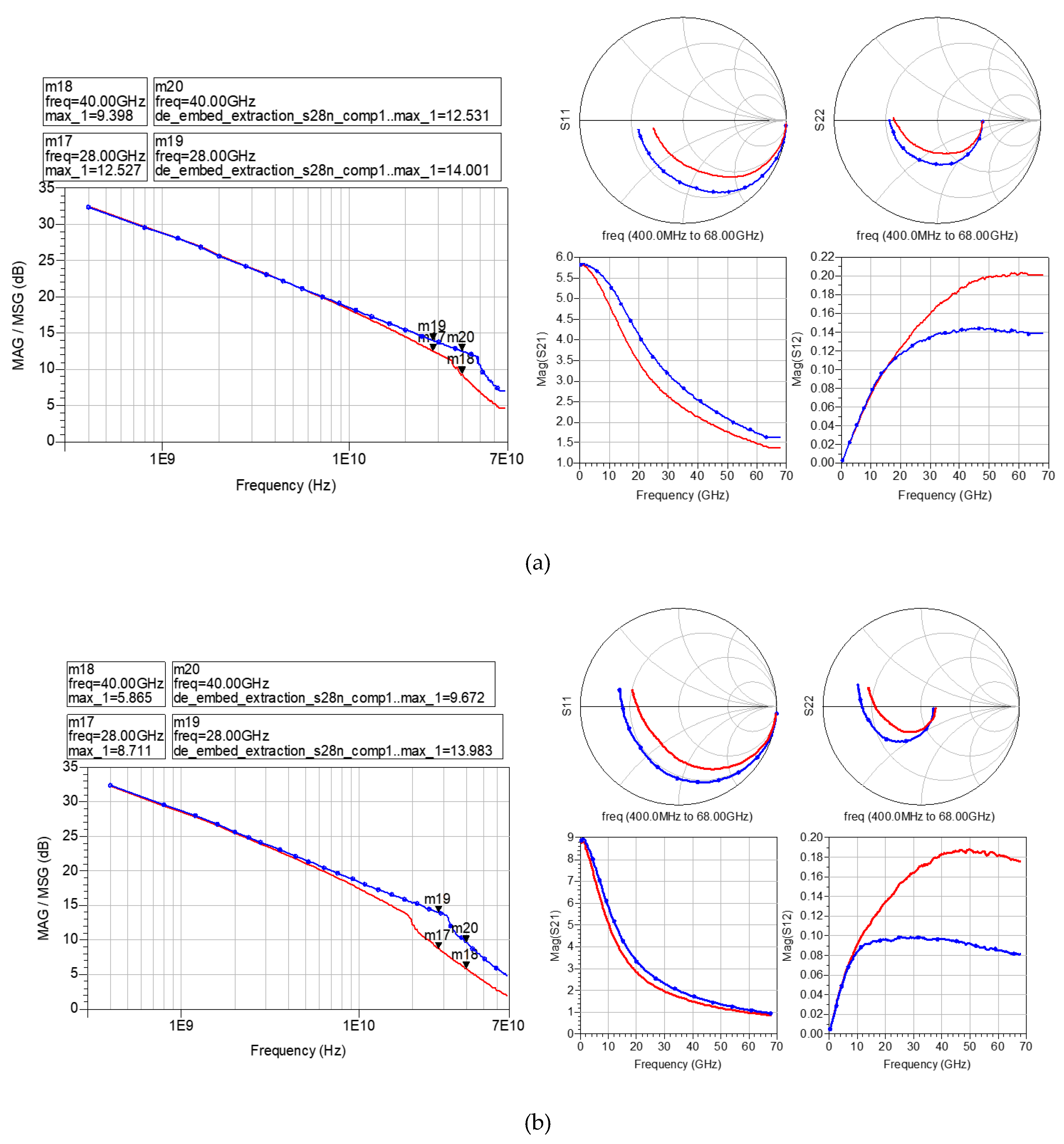
Figure 4.
Comparison of MAG/MSG according to transistor sizes (all transistors are ring type and LVT_NFET_RF).
Figure 4.
Comparison of MAG/MSG according to transistor sizes (all transistors are ring type and LVT_NFET_RF).
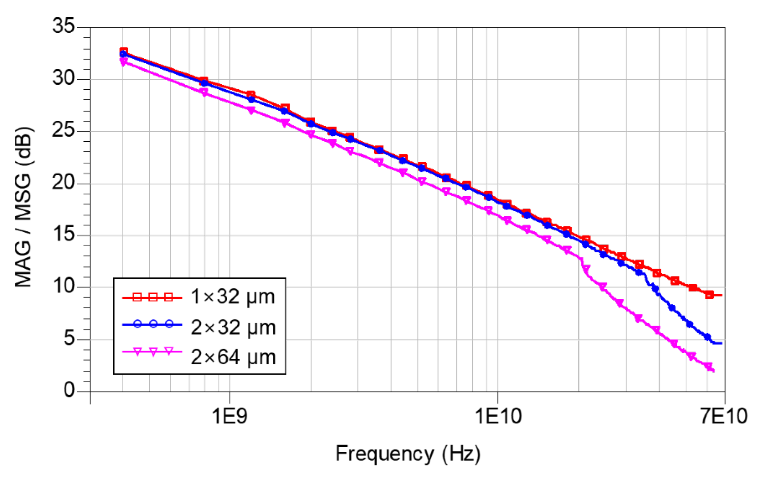
Figure 5.
Layouts of (a) CPW, (b) GCPW, (c) FCPW and (d) total view of transmission line test patterns.
Figure 5.
Layouts of (a) CPW, (b) GCPW, (c) FCPW and (d) total view of transmission line test patterns.
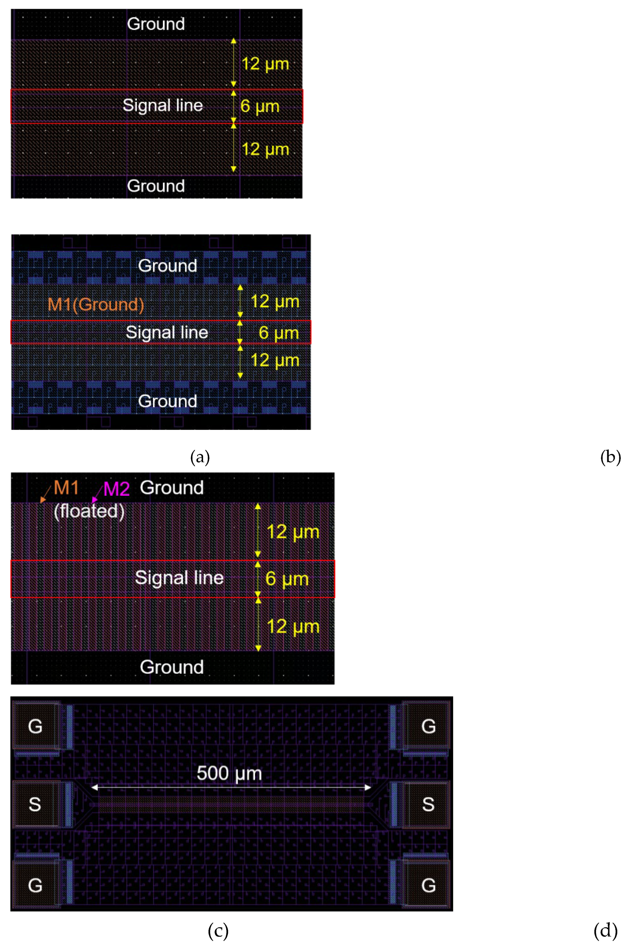
Figure 6.
Comparison of MAG/MSG between the fabricated transmission line test patterns.
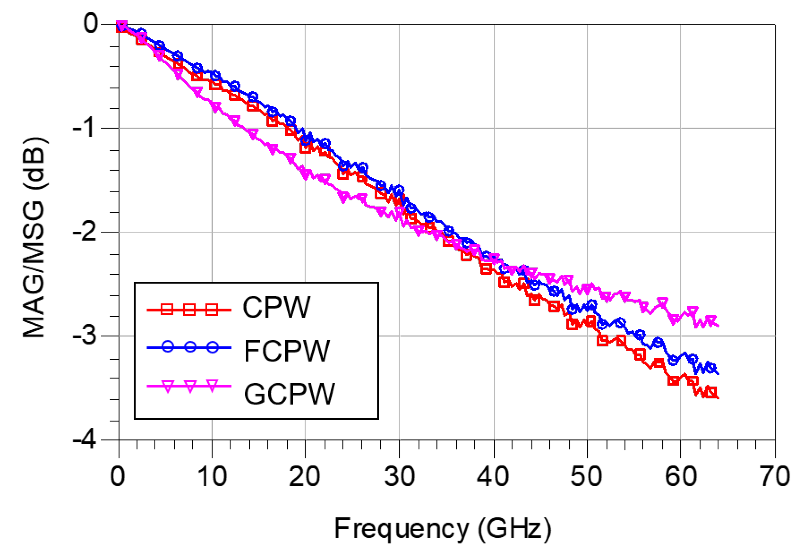
Figure 7.
Transmission line structure (left) and schematic of a typical DA (right).
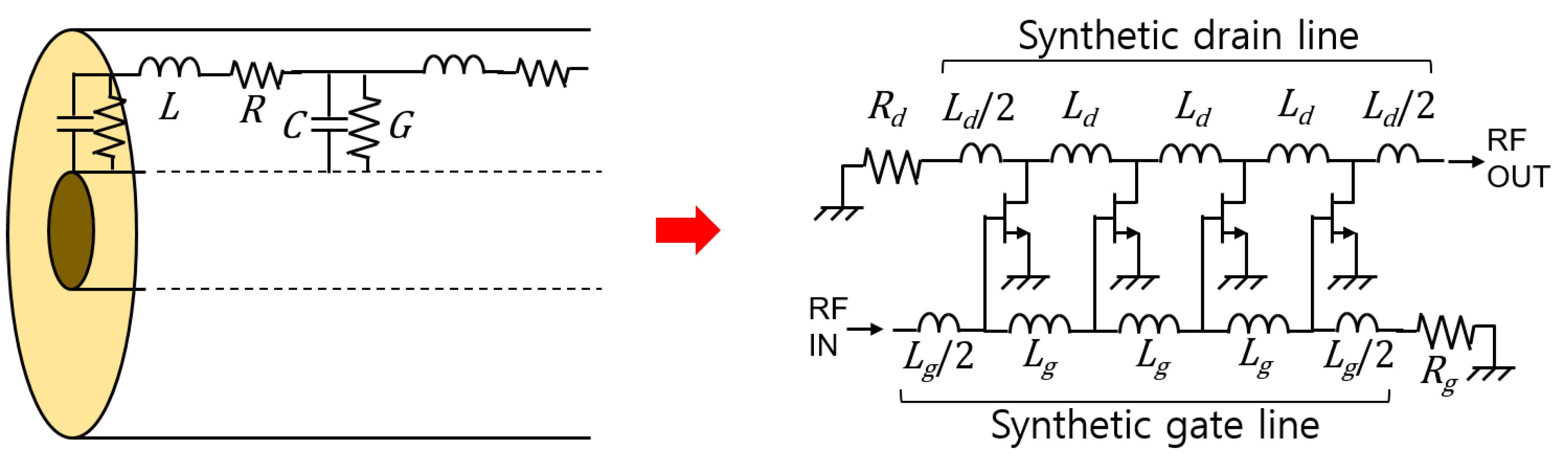
Figure 8.
Circuit schematic of the proposed DPA.
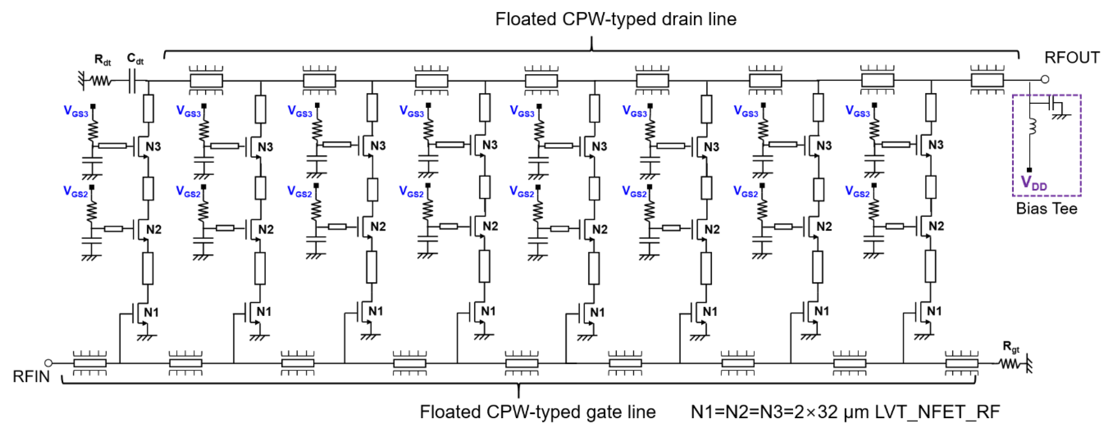
Figure 9.
Layout of the proposed DPA.
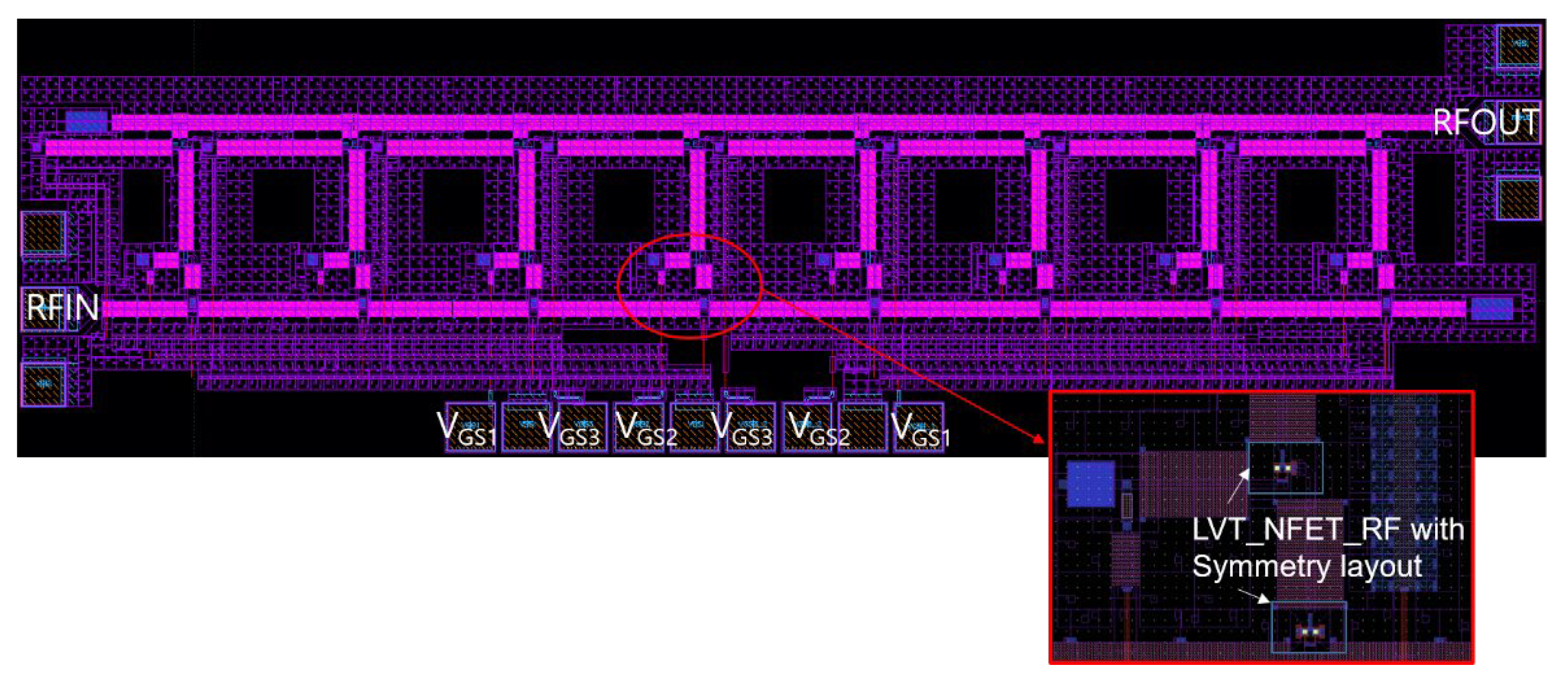
Figure 10.
Small signal S-parameters of the DPA simulated by ADS.
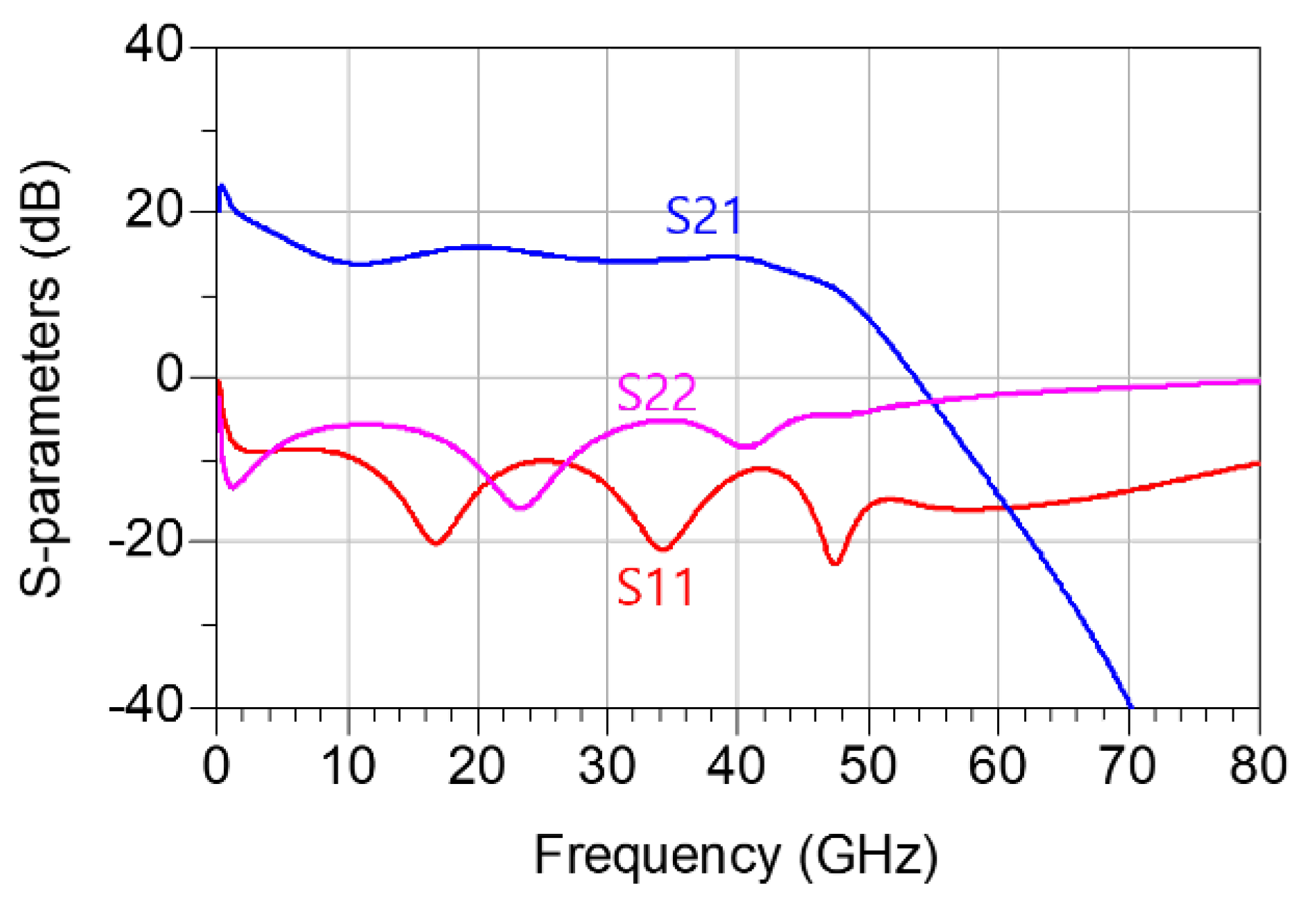
Figure 11.
Chip photograph of the proposed DPA (chip size: 3.0 mm × 0.75 mm).
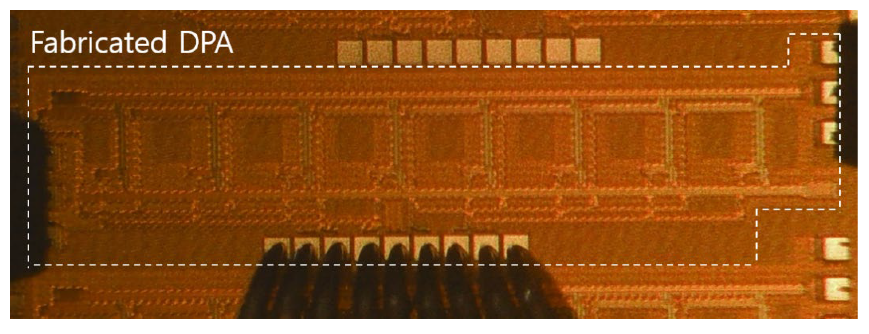
Figure 12.
On-wafer measurement setup (a) Small-signal (b) Large-signal.
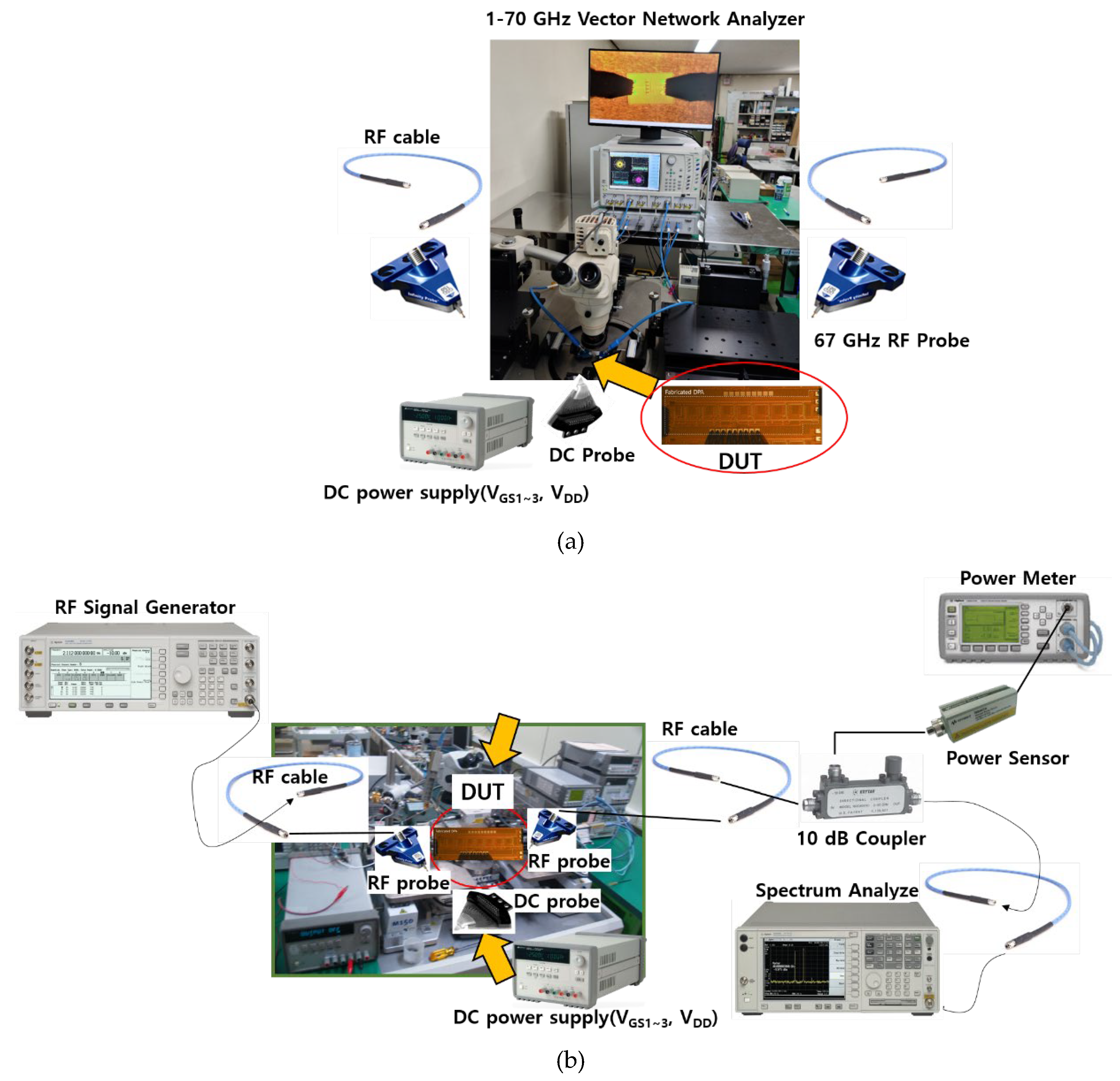
Figure 13.
Measured S-parameters of the proposed DPAs.
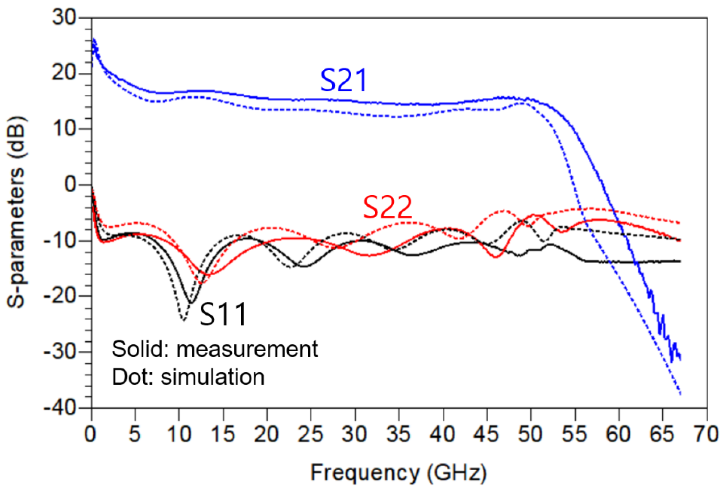
Figure 14.
Pout, DE and PAE measurement results of the fabricated DPA according to frequencies.


Table 1.
Public and private utilization status of 5G spectrum in major countries around the world.
| Sub6 (GHz) | Millimeter-wave (GHz) | |
|---|---|---|
| Germany | 3.4-3.7 (O1), 3.7-3.8 (P2) | 24.25-27.5 (P) |
| Japan | 3.6-4.1, 4.5-4.6 (O), 4.6-4.9 (P) |
27.0-28.2, 29.1-29.5 (O), 28.2-29.1 (P) |
| France | 3.4-3.8 (O), 2.575-2.615 (P), 3.8-4.0 (P) |
26.5-27.5 (P) |
| Republic of Korea | 3.42-3.7 (O), 4.72-4.82 (P) | 26.5-28.9 (O), 28.9-29.5 (P) |
| U.K | 3.4-3.8 (O), 3.8-4.2 (P) | 24.25-26.5 (P) |
| USA | 3.55-3.7 (P), 3.7-3.98 (O) | 24.25-25.25 (O), 27.5-28.35 (O), 37-40 (P) |
| China | 2.515-2.675 (P), 3.4-3.6 (P) | - |
1O means official use. 2P means private use.
Table 2.
Performance comparison of reported wideband SiGe HBT/CMOS power amplifiers with the octave bandwidth beyond 30 GHz.
Table 2.
Performance comparison of reported wideband SiGe HBT/CMOS power amplifiers with the octave bandwidth beyond 30 GHz.
| Reference | Technology | Frequency (GHz) | SS Gain1 (dB) | Pout (dBm) | PAE/DE (%) | Chip area (mm2) |
|---|---|---|---|---|---|---|
| [9] | 65 nm CMOS | 0.5 – 38 | 11 – 15.7 | 12.8 – 21.8 | 2.0–25.2/3.3 – 35.3 | 3.30 |
| [11] | 130 nm SiGe | 14 – 105 | 6 – 12 | 4 – 17 | 1–12.6/2 – 15.1 | 1.51 |
| [12] | 22nm FD SOI CMOS |
0.4 – 31.6 | 11.6 | 14.5 – 16.4 | 11 – 17.2/ – | 1.5 |
| [13] | 45nm SOI PMOS |
DC – 120 | 16 | 17 – 23 | 5–192/6 – 24 | 1.32 |
| [14] | 130 nm SiGe | DC – 110 | 10 | 12.5 – 17.5 | 3-13.22/5 – 16 | 2.18 |
| [15] | 180 nm CMOS | DC – 35 | 24 | 9 – 13.22 | – | 0.83 |
| [16] | 65 nm CMOS | 3 – 53 | > 9.3 | 10.95 – 14.93 | –/3.63 – 8.95 | 1.33 |
| This work | 28 nm CMOS | 1.0 – 50.8 | 15 – 22 | 11.3 – 20 | 1.6 – 14.1/2.8 – 18.7 | 2.25 |
1It means small-signal gain. 2Some data was estimated from the reported paper.
Disclaimer/Publisher’s Note: The statements, opinions and data contained in all publications are solely those of the individual author(s) and contributor(s) and not of MDPI and/or the editor(s). MDPI and/or the editor(s) disclaim responsibility for any injury to people or property resulting from any ideas, methods, instructions or products referred to in the content. |
© 2024 by the authors. Licensee MDPI, Basel, Switzerland. This article is an open access article distributed under the terms and conditions of the Creative Commons Attribution (CC BY) license (http://creativecommons.org/licenses/by/4.0/).
Copyright: This open access article is published under a Creative Commons CC BY 4.0 license, which permit the free download, distribution, and reuse, provided that the author and preprint are cited in any reuse.


