
Submitted:
19 March 2025
Posted:
20 March 2025
You are already at the latest version
Abstract
Transition zones are in the places on the track with a change in the main composition of the railway infrastructure. There are many sections with a sudden change in the stiffness of the structures built. When the trains are running, a longitudinal shock wave is created from the wheels, which hits these building objects with a higher stiffness and deforms the surroundings of these zones. The most outstanding attention should be paid mainly to the transition points from the fixed track to the classic track with a track bed, including objects of the railway substructure such as bridges, portals of tunnels, etc. As part of the research sections on the main corridor lines, a long-term inspection and monitoring were carried out using the KRAB trolley with a continuous measurement system. Height changes in the deflections of rails are evidence of their behaviour. The measurements took place on a fixed track and a track with a ballast. Changes in the height jumps between the fixed railway track and the track with a gravel bed are significant and have been recorded since the tracks were put into operation. These certain height deflections allow designers to develop new, more durable construction designs.
Keywords:
railway infrastructure
; transition zone
; change in stiffness
; long-term monitoring
; height deflections of rails
; fixed railway track
; track bed
1. Introduction
Increasing the quality of the design and construction of the tracks for railway vehicles and improving the safety and comfort of their driving are among the main tasks of the international railway group UIC and the European Community. Depending on the quality of the designed track, the smooth running of train sets may be disturbed by some objects built into the tracks. The shock wave hits these objects, spreading from the wheels. These objects are called transition zones (TZ), in which the rail upper structure and lower substructure objects suddenly change the track's stiffness. They are located on all railway lines as a transition between a fixed railway track (FRT) and a classic one with a gravel track bed (railway ballast) or between gravel track construction and reinforced concrete structures embedded in the railway substructure of the fixed track of bridges or tunnel portals.
We know from railway practice and research tasks that these locations cause complications in structural design, construction, and operation of train sets over these short sections. If a train set travels on a fixed track and its section ends, it will hit the ground in the transition zone, i.e., the track ballast bed. This transition phenomenon also occurs at bridge structures. The trains must also travel in reverse along this transition section. Impact forces are generated, which cause the track's geometric directional and vertical position to collapse. The same applies if objects (for example, bridges, tunnel portal foundations, tunnel tubes, etc.) are located on the railway substructure with a continuous track bed above it.
If the rail bed were continuous, two options would arise. If it is a fixed track, it is in a long-term, high-quality, sustainable condition but cannot be tamped. Similarly, if the track is on a continuous track bed, there are directional and height deformations of the track position and height caused by traffic. Still, the track is tamped regularly with mechanical tamping machines to the designed or required position and height. In both cases, it is necessary to ensure that the time interval between their position and height adjustments is as long as possible. This can be achieved with high-quality constructed track sections with an emphasis on the behaviour of objects in transition zones. A malfunction of a part of the train set or the poor condition of the structures on the track may cause accidents in these sections. The primary cause, the "trigger", may be hidden in this poor directional and elevation position of the track in each section with deformations, i.e., they may trigger the cause of the accident. Conversely, in a poorly constructed transition zone, the forces acting on it can degrade the railway track and the rolling stock of trains.
Sanudo et al. [2] address transition zones with increased rigidity of the railway body by adding additional rails to their research. The data are measured in the track using the Dinotrans system. It is one of the new solutions that can be applied at the transition from a solid slab to a rail bed, of course, with flexible rail fastening. Accelerometers and extensometer sensors monitor these data.
Another option for modifying the transition zone is the material composition of the underlying layers and building objects in the lower part of the railway line, as solved by Jain et al.'s research [3]. This comprehensive study addresses the persistent issue of transition zone degradation in railways, evaluating the efficacy of the most used mitigation measures and proposing a novel Safe Hull-Inspired Energy-Limiting Design of a transition zone structure. These same researchers in [4] solve railway transition zones' experience with higher degradation of objects in these stressed sections and try to delay these processes, leading to uneven track geometry. Deformation resistance is important for maintaining a long-term stable position and height of the tracks in this force-intensive section.
Deformed areas of the railway body, such as sections in front and behind bridge structures, which are prone to differential settlement and heave during train loading, are addressed in the research of Akshay et al. [5]. Structural layers and embedded structures degrade faster in these critical parts at the supports of railway bridges due to the deterioration of their deformation resistance in the transition zones. New designs of these track sections at bridges are important to improve the stiffness of the track while preventing deformations.
The problem of high-speed railway transition zones is dealt with by Ping H. et al. [6] within the framework of sections near bridges and culverts. They monitor the dynamic response, structural parameters and material properties of individual layers when changing their proposed parameters to improve the stiffness of the railway infrastructure.
Park, S. et al. [7] solve the Rheda 2000 type rigid track in the transition zone areas on high-speed lines at 280-300 km/h speeds. The numerical analysis includes the definition of the rigid reinforced concrete track and the moving load of the railway line. The developed model offers the determined values in the transition section of the railway line. These transition zones are vulnerable, and the result is the deformation of the track geometry.
Authors Fortunato E. et al. [8] address transition zones near bridges and other construction objects of the lower railway substructure in their study. With increased stress on railway structures from moving loads, degradation of these objects occurs. These objects in transition zones need to be regularly monitored, maintained or reconstructed. Therefore, the authors address the task of reducing financial costs for maintaining these objects by employing model design. The authors Wang W. et al. [9] monitored the transition zones in their research, not only from the point of view of the structural layers but also from the possible increased humidity in these structures. High humidity also presents significant problems for the transition zones, which are the causes of the degradation of building elements in the track. Increased humidity causes a decrease in the stiffness of the structural layers.
The team of authors Lee J. et al. [10] deals with the solution of structural parts to ensure a gradual change in the stiffness of the roadway. They insert various elements into the transition zone to increase the stiffness of the structural layers. Experiments were carried out on the track at the transition from solid slab to gravel, at bridges and tunnels.
Tan S.H. et al. [11] present embedded reinforced concrete slabs that are highly effective in reducing the vibration height response in transition zones. The authors point out that if the resistance of these building structures is more excellent, then the vibration resistance is also better under moving loads during the movement of train sets.
2. Research Design and Methods
Monitoring the health condition of the objects of the railway lower substructure of the transition zones would be appropriate, but the monitoring is carried out on railways as follows. Such monitoring and evaluation of the conditions of the track of the entire carriageway take place with the help of hand-held measuring devices (trolleys), especially with the measuring wagons based on the measurements of the track parameters. The reconstruction measures of the lower substructure objects will only be started based on the detected deformations of the geometrical position of the track. The limits for corrective interventions in the track are given in the prescribed criteria of standards and regulations (further on in the text). In our research, we perform very detailed measurements of the geometric position and heights of the track on the transition zones.
If transition zones do not maintain the designed or prescribed geometrical position and heights of the tracks for a long time, there would be increased costs for their maintenance during their operation and unwanted deformations of parts of rolling stock driving on them from wheel impacts.
The procedures and accuracy of KRAB measurements have been verified, for example, in [12,13]. During the research tasks, numerical models of transition zones and measurements in the track were developed. The models confirmed the accuracy and correctness of the measurements. Another comparison with geodetic methods found that the KRAB system measures heights more accurately ±1 mm (mean error of height determination at the measured point) than those determined from geodetic measurements. This is a relative determination of heights, but on a long 200 to 600 m section of the track axis on both R/L rails (right/left). For example, if we look at the figures in this paper, the individual measurements follow each other at time intervals. This means that each new measurement confirmed the values of the previous measurement.
Research has been carried out at the Department of Railway Engineering for several years since 2013 at transition zones near the railway tunnel in the town of Trencianske Bohuslavice and the railway bridge over the Vah River in Trencin, both with FRT for a speed of 160 km/h in Figure 1a. The research involves continuous measurements, ensuring a comprehensive understanding of the transition zones. Currently, a new experimental section near the Milochov bridge near the city of Puchov is being prepared with a continuous gravel bed. The measurements were carried out continuously with the KRAB measuring device [1]. In addition, sensors for measuring the forces between the rail and sleeper and acceleration and speeds will be built into the upper part of the railway structure (for measurements from 2025). Measurements will be made while the train sets are passing. In the first phase at the Milochov bridge (in the 3rd stage measurement), based on the previous monitoring, the positions of these devices (sensors) in the transition zones will be determined, and now preparation is underway.
In the inspection and monitoring courses, research is conducted on the transition zones built into the railway's upper and lower structures. The train creates a longitudinal shock wave, which hits a solid object, such as a reinforced concrete slab (FRT) or, for example, the construction of railway bridges, tunnel portals, etc. The research was carried out on the track with these objects, either with FRT or a classic track bed.
Experimental measurements were performed continuously in a measurement and evaluation step of 25 cm in Figure 1b. The accuracy of the KRAB measuring device is reliable ±1 mm of the average height determination error due to the deflection of the LHD rails R/L, which is also documented by the graphic outputs in individual stages. The same waves are recorded everywhere and, what is essential, the curves of the graphs are transformed gradually (also confirmed from previous research measurements). Each new stage of measurement on the transition zone as part of the monitoring confirmed the curve of the last measurements and certain new developments of the LHD deflection of the deformation of the heights of the rails over time.
The authors mentioned in [2,3,4,5,6,7,8,9,10,11] deal with transition zones from specific perspectives because various forces are manifested in these parts of the tracks, which causes the degradation of individual structures. Significant findings include the determination of the current condition of the tracks on the railway line as a result of the action of these particular phenomena. The resulting deformations of the track geometry, its position and its height are dealt with by the research activity of the Department of Railway Construction [12,13,14], which was carried out on transition zones with fixed track (FRT only). The research presents the transition of a solid reinforced concrete track to a gravel bed, including structures with FRT, such as small and large bridges, tunnel portals, etc., for a speed range of 160 km/h. These places with a sudden change in track stiffness are monitored continuously in time intervals using the KRAB device at a specific measurement step.
Authors Hodas S. et al. [12] monitor the deformations of the track axes in the transition zones, where the solid reinforced concrete slab begins or ends and the transition to the classic track with a gravel bed occurs. Monitoring was carried out using the KRAB device, and heights were determined using geodetic measurements. The resulting values of both methods were compared with each other.
Another undesirable phenomenon for transition zones is the disruption of structural layers by frost in the winter, which Hodas S. addresses in research [13]. The paper describes the possibilities of frost protection of structural layers using materials with low thermal conductivity coefficients. New frost protection solutions were proposed using numerical models.
Monitoring transition zones of bridge structures is finalized in Hodas S. et al. [14], where the same phenomena occur in every transition zone.
Basic experimental measurements as part of monitoring were already carried out after the new corridor line was handed over to operation near the Milochov bridge in this new time stage, 4/2023 and 9/2023. We are expected to install the sensors in the upper rail superstructure to these sections and proceed with further measurements in 2025 (preparation of these experimental sections during 2024 and 2025).
The various types of materials that can be built into the track in the transition zones are tested at the testing stands laying in the laboratories of the Department of Railway Construction.
Continuous monitoring by sensors in transition zones would be the right thing to do, but few objects (1 to 3 objects) would be monitored, including high financial costs. However, our task is to monitor several hundred transition zones in different railway infrastructure lines based on the actual track geometry (position and height). These are sections between the solid reinforced concrete track and the so-called "jump" to the track bed. Conversely, train sets must "step up" from the gravel bed to the solid track, the other possibilities are parts near bridges, tunnel portals and culverts.
3. Results and Discussion
A new section with input measurements on the track exclusively with a track bed was also included in the measurements (previous monitoring since 2013 always with FRT). So far, two measures have been carried out on the new sections, i.e., after putting the railway line into operation and then after five months of operation. The characteristic features of the shape of the track geometry include the longitudinal height changes of the deflections (LHD) of the R/L rails. In the transition zone and its adjacent sections, experimental measurements are carried out in the railway substructure at points S1 to S4, i.e., determined in certain characteristic places observed by long-term monitoring in particular transition zones in 2013-2024 [13,14].
In 2020-2023, the individual tasks of these activities were covered by the scientific research Izvolt L. et al. [15]. The measurement locations of sensors S1 to S4 in Figure 2 are built into the lower layers of the railway structure from the beginning of the measurements but do not belong to the monitoring using the KRAB device. They are used to measure the action of a force from the axle pressures of a moving train load in a particular layer (force measurement, accelerometers, etc.). Sensors are currently being prepared in the same positions S1 to S4, of the upper parts of the railway superstructure.
Subsequently, the values of measurements during the movement of train sets at 60, 100, 120 and 160 km/h will be compared and the resulting degradation detected from monitoring by the KRAB device. So far, they are on the section in the transition zone of the bridge structure with the track bed, but other sections are being prepared at the places of the so-called "jump" from the fixed track to the track bed. The problem is regular tamping with automatic tamping machines (ballasted track), but further experimental sections are being prepared at the transition point to the fixed railway track according to the curves in Figure 4 to Figure 7 in accordance with monitoring.
3.1. Bridge Objects – Ballasted Track
First, we point out the bridge object with adjacent parts of track sections, whose measured LHD values of rails R/L are shown in Figure 2. Markings "ZA1", "ZA2", "BA1", and "BA2" are marked directions of the location of measured transit zones near objects (bridge, tunnel), for example, ZA - towards the city of Zilina, BA - towards the city of Bratislava, 1 and 2 are track numbers. In the figure, the transition zone is in the railway substructure (bridge), where the railway's upper structure forms a classic ballast bed. The “arrows” in the figures represent the prevailing direction of trains (approx. 80 %). We can conclude that the results show characteristic deflections of the track geometry after the train sets pass through the track. The figure shows the bridge object and the positions of the sensors for measuring forces S1 to S4 under the R rail (they are not the subject of this text and are prepared for subsequent physical measurements in the track in 2025, not only monitoring using the KRAB trolley).
The lower parts of all figures with LHD curves present the composition of the structural parts of a particular transition zone (e.g., BRIDGE, TUNNEL, PORTAL, BALLAST, FRT, FRT-BLOCK, TUB, etc.).
Figure 2.
Longitudinal height deflection LHD by KRAB, track No. 1 – Milochov bridge: (a) L – left Dyn_L; (b) R – right Dyn R, track with railway ballast and using automatic tamping machines.
Figure 2.
Longitudinal height deflection LHD by KRAB, track No. 1 – Milochov bridge: (a) L – left Dyn_L; (b) R – right Dyn R, track with railway ballast and using automatic tamping machines.
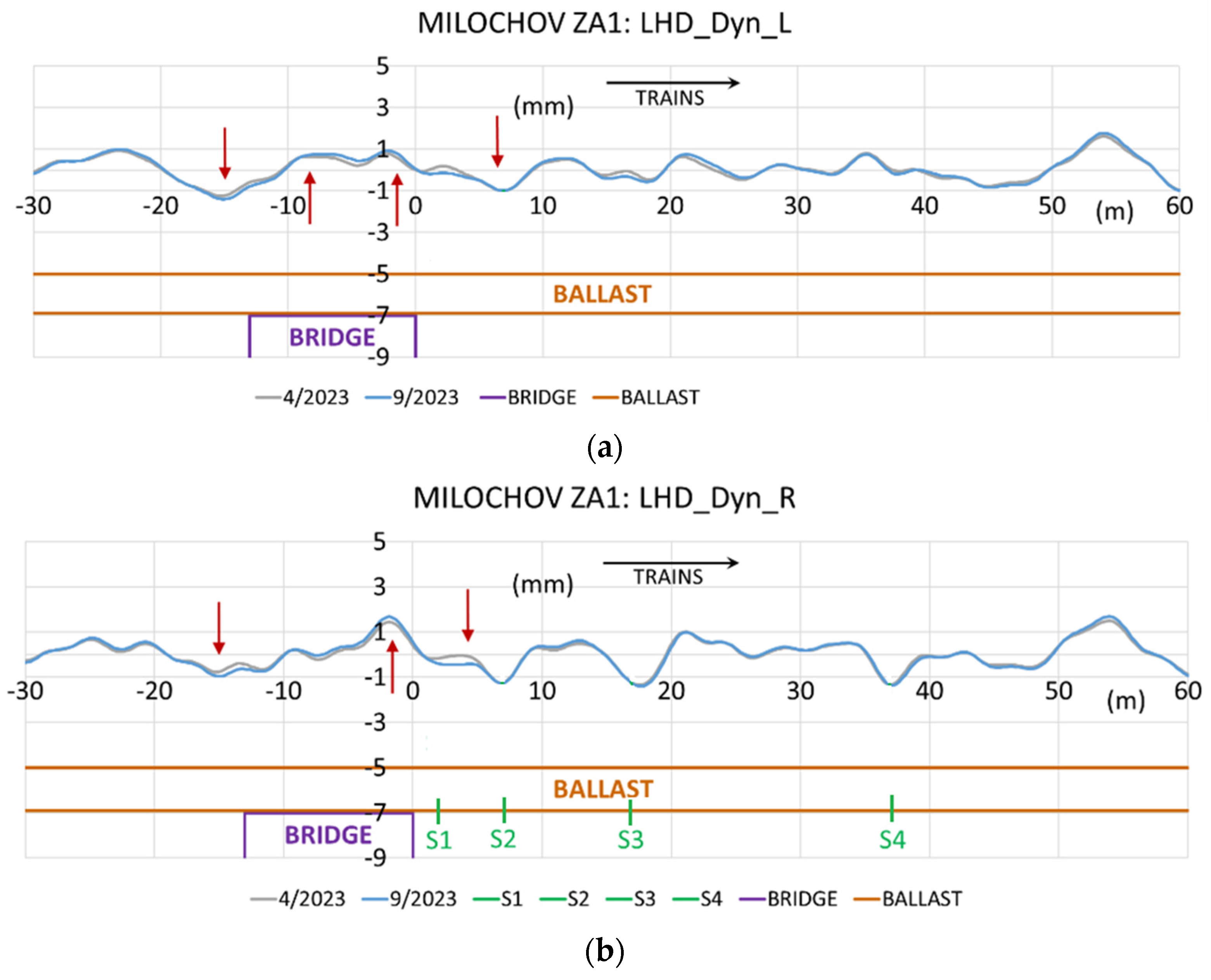
The height deformation of rail R in Figure 2b is more significant than rail L in Figure 2a because it is the outermost rail R on the slope of this embankment. Although the gravel bed decreases to a minimal extent due to running away into the hill, the track meets the criteria for operation. Upcoming measuring sensors S1 to S4 are also located under this rail R, which caused small height shifts in these places. After the next tamping of the track with tamping machines, the heights will be levelled like the L rail in Figure 2a.
These resulting deflections of the LHD height geometry of the R/L rails are evident in the details of this bridge object in Figure 3. We note that the height waves at the LHD in the continuous track bed are not as significant as at the ends of the fixed carriageway. This is because a layer of the track ballast dampens the sudden transition change in the railway substructure to the bridge object. As a rule, the track bed is tamped with tamping machines to the required prescribed geometric position and heights of the track (in contrast to a fixed railway track).
Regular tamping works with automatic tamping machines (to the prescribed, designed position and heights) do not allow monitoring the time course of the LHD deflection with the KRAB trolley and similar devices. Evaluations can only be done at intervals between two tampings of the track bed, as tamping returns the heights to the same prescribed height position.
This is confirmed by measurements on the fixed railway track near the tunnels and the classic ballasted track (Chapter 3.3). A railway line with a classic construction is generally tamped to the projected height (or optimised, prescribed) regularly according to the criteria for evaluating the operational condition in STN 736360-2 [16] for track monitoring, unlike FRT, where tamping works are not possible. These are operational deviations for the AL level – monitoring limit, IL – intervention or repair limit, and the IAL limit deviation – the limit of immediate intervention in the track.
Shocks and shock waves are expected at construction sites under the track bed in the railway subgrade. The track will more easily guide the vehicle over these objects in places of stiffness change. This applies if the track is correctly and qualitatively built without subsequent deformations. The FRT demonstrates long-term stability; only when the FRT is affected by a change in the stiffness of the lower track structure does it adjust in height - it deforms.
3.2. Bridge Objects – Ballasted Track
The following results of experimental measurements when changing a track with FRT to a track with a track bed point to problems when changing the stiffness of the railway infrastructure. In these places, one structure is interrupted, and there are significant shocks from the wheels of train sets, for example, Figure 4 to Figure 7.
To comparison, measurements are presented from the monitoring of a direct transition (at the point of change in track stiffness) from a fixed railway track to a track with a railway bed, for example, sections near the Turecky Vrch tunnel near the city of Trencianske Bohuslavice according to figure 4 or near the bridge in the town of Trencin in Figure 7. Reinforced concrete tubs for the track bed are designed here as transition zones. The zero point "0" represents this transition ("jump") where structural layers and objects are deformed, and the resulting values are R/L rail geometry position LHD deflections.
Figure 4.
The overall evolution of LHD deformation – transition zone Turecky Vrch, track. No. 1: R – right Dyn_R.
Figure 4.
The overall evolution of LHD deformation – transition zone Turecky Vrch, track. No. 1: R – right Dyn_R.
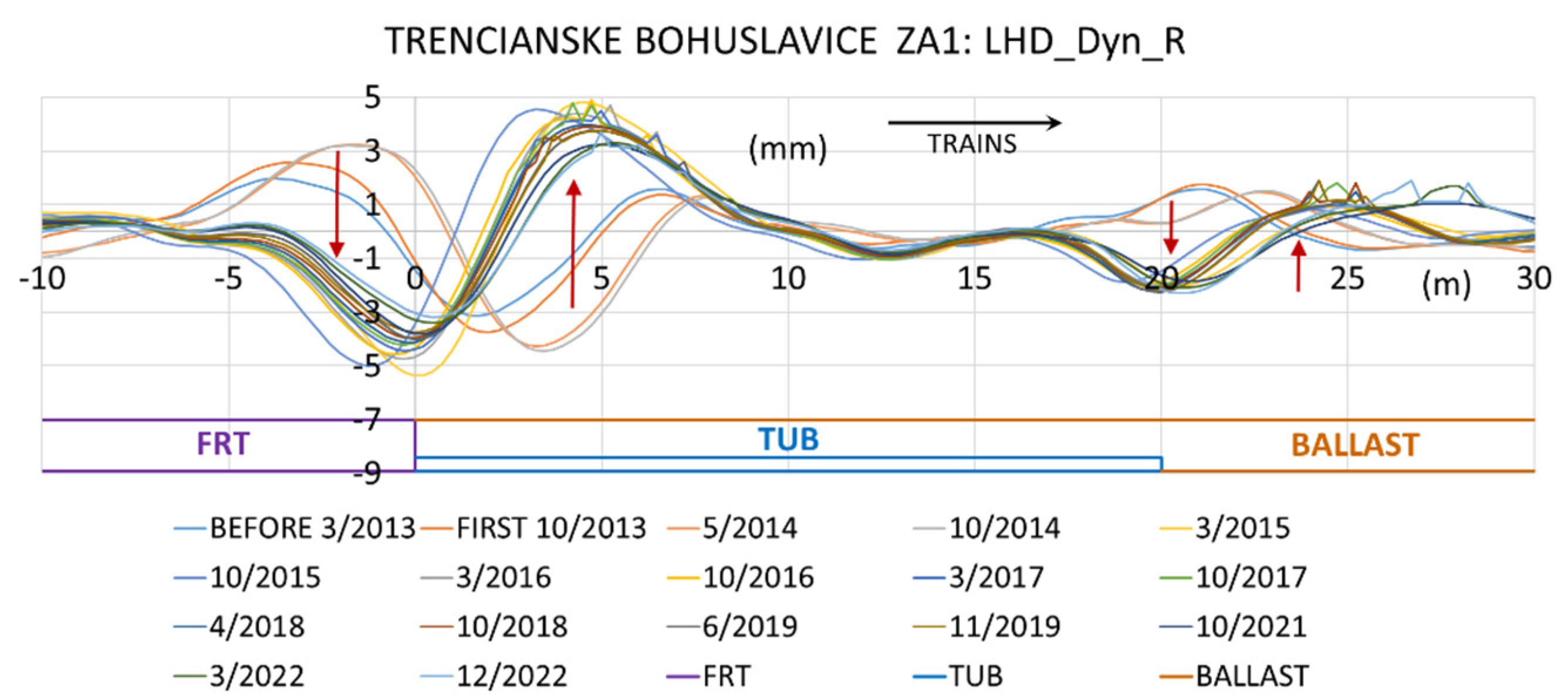
Figure 5.
Steady height deformation LHD - transition zone Turecky Vrch, track. No. 2: R – right Dyn_R.
Figure 5.
Steady height deformation LHD - transition zone Turecky Vrch, track. No. 2: R – right Dyn_R.
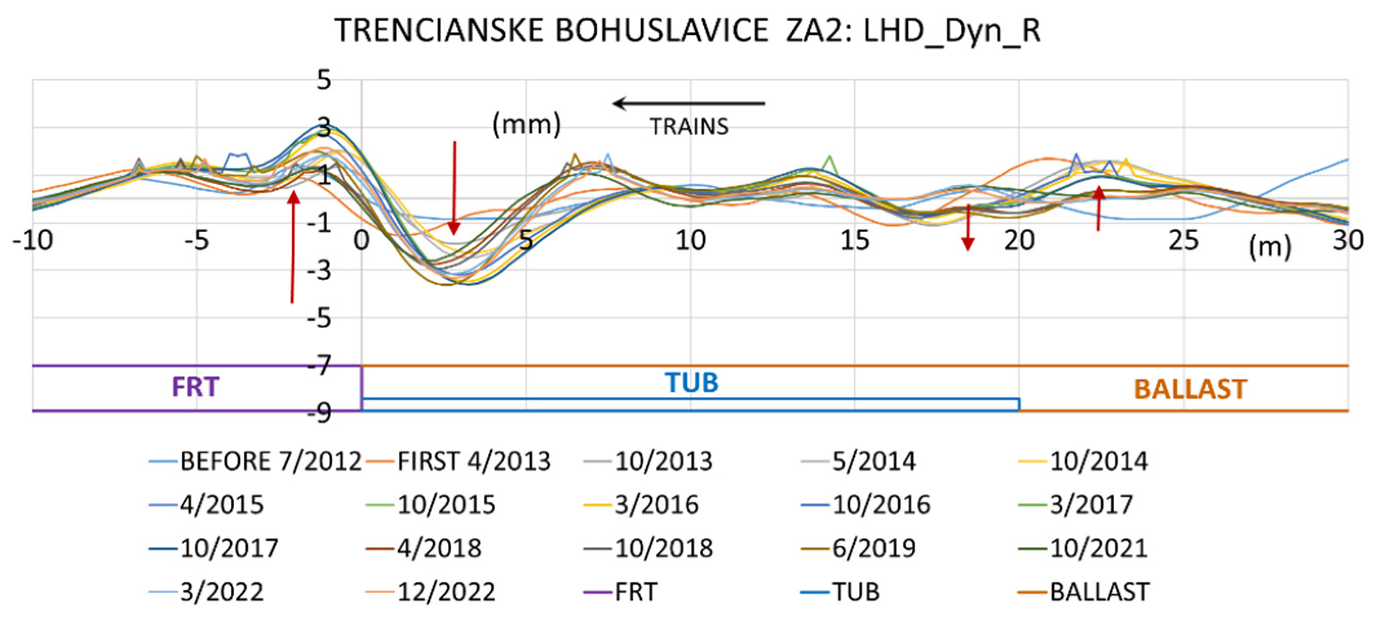
Figure 6.
Overall LHD development and stabilisation deformation – transition zone Trencin, track. No. 1: R – right Dyn_R.
Figure 6.
Overall LHD development and stabilisation deformation – transition zone Trencin, track. No. 1: R – right Dyn_R.
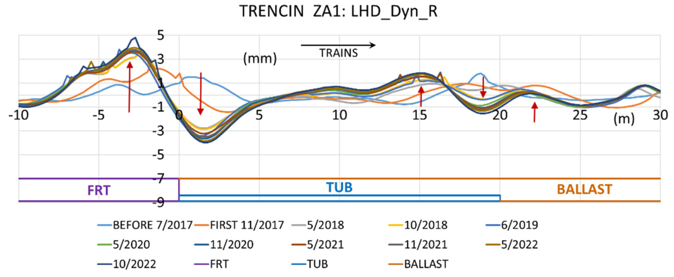
Figure 7.
Overall LHD development and stabilisation deformation – transition zone Trencin, track. No. 2: R – right Dyn_R.
Figure 7.
Overall LHD development and stabilisation deformation – transition zone Trencin, track. No. 2: R – right Dyn_R.
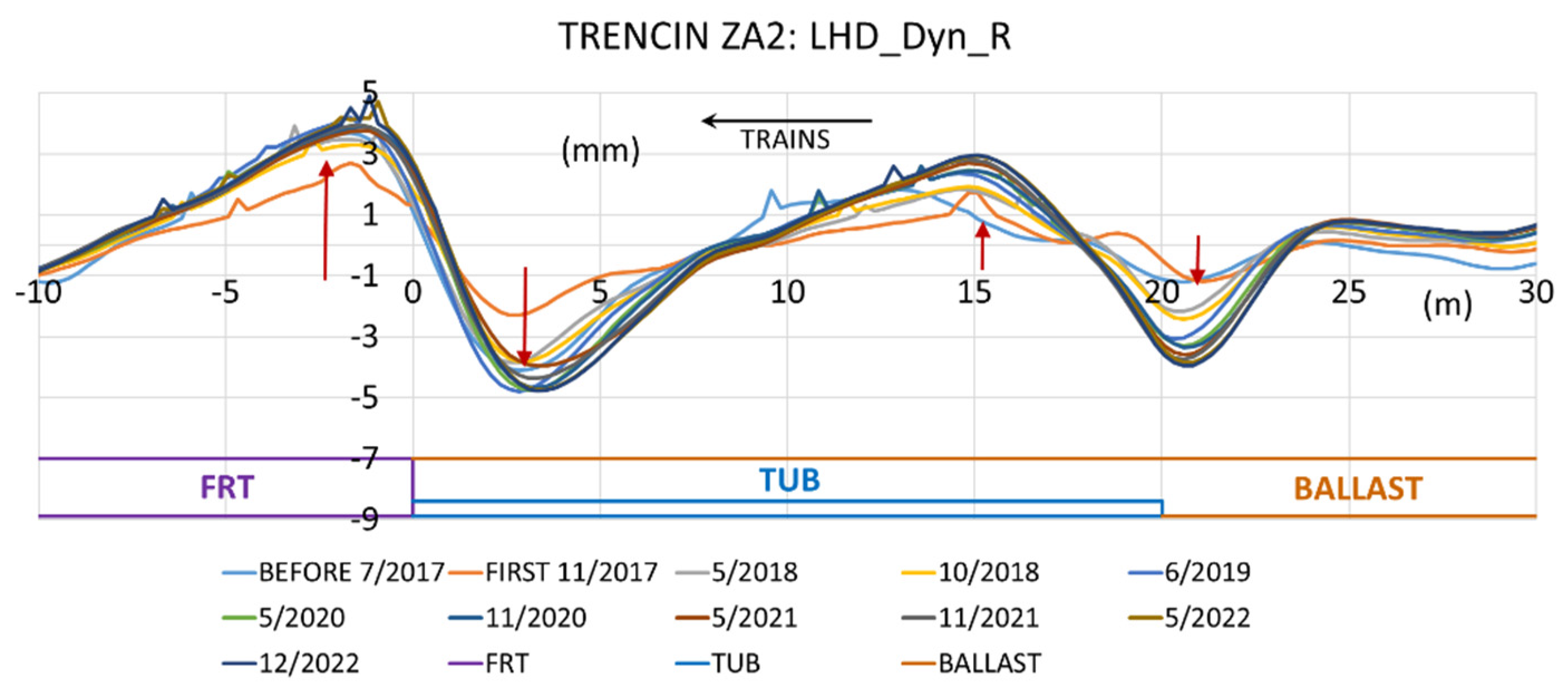
Based on the results of long-term experimental measurements, we can conclude that the transition zone with its beginnings and ends of the fixed railway track (the ends of the FRT), where there is a transition from a reinforced concrete slab to the track bed, or the end of a bridge structure without a track bed, causes more significant problems on the railway line. In contrast to the FRT, in the transition zone from the gravel track bed (near FRT), for example, at a bridge object located at the railway bottom of the track, here, the track can be tamped regularly with automatic machine tampers (provided that the structural layers of the railway's lower substructure under the transition zone can affect their deformations, i.e., the TZ).
During this transition at the end of the FRT structure, a "vertical cut" occurs in the longitudinal profile of the track, causing a significant change in its stiffness. This start or end of FRT at zero point "0" approximately above 1 m in the track bed is tamped poorly. Also, for this reason, "jumps" (deformation waves) arise, created by the forces of the wheels of train sets at these points.
The research shows that the most significant height wave of the change in the geometry of the R/L rails occurs at the transition point, and in the case of the constructed reinforced concrete tub, also at its end (schemes – lower parts of figures), but approx. with half the value of the height/depth of the wave ("double jump" height curve, in this case, the length of the tub is 20 m). When the trains travel in the opposite direction, the material at this point is pushed under the fixed track or the transitional reinforced concrete tub, or the structural layers of materials under the concrete objects or the reinforced concrete tub of the transition zone are deformed.
These longitudinal height deformations (LHD) of the R/L rails are significant (higher values) mainly because they are places on the railway track where there is a transition between the reinforced concrete slab (FRT) and the railway ballast. For this reason, research is being carried out on these sections with a change in the stiffness of the railway track. In addition, according to Figure 4, we assume changes in the heights of the underlying layers, as it is a high railway embankment of 6 to 8 m, and the said section has problems during the entire period of operation of the railway line. According to this figure, we can also state that the first stage measurements before and after the track is put into operation are curves that indicate that at the point "0", where the end of the reinforced concrete block FRT (its fall and subsequent extrusion of the material).
Even if these height waves of the geometric position of the R/L rails (LHD) are detected, solved and analysed, the track in the given section meets the criteria of operational deviations. As an illustration, the resulting graphs from measurements by the continuous KRAB trolley with all its parameters are shown in Figure 8. The primary task of the research is to reduce the effects of shocks from the wheels of train sets, vibrations, deformations, etc., on objects of track construction, including stress and wear of structural parts of train sets, and increase the comfort of driving on the track (people, goods). If these deformations are not considered, the geometric position and heights may collapse at the point of change in track stiffness.
These limit values are differentiated by colour for the specific level of intervention in the track: AL level – monitoring limit (green), IL – intervention or repair limit (blue), and the IAL limit deviation – the limit of immediate intervention in the track (red). The limits are set according to the importance of the track, for example, the European railway corridor with a track speed of 160 km/h.
3.3. Tunnel Portals – Ballasted Track
Other track stiffness changes, such as tunnel portals, behave similarly to the vertical deformation deflections of the track geometry.
Data are monitored in the measured research section of the transition zone near the portal of the Milochov tunnel, according to Figure 9 (first measurement 9/2023), where there are height changes on the R/L rails. Since it is a classic construction of a railway line with a track bed, the section is tamped with automatic tamping machines to the prescribed geometric position and height of the track according to the AL, IL, IAL criteria according to the standard STN 736360-2 [16].
3.4. Tunnel Portal – Fixed Railway Track
In the case of tunnels with fixed railway track (FRT), the research monitoring registered the height changes of the wave of the geometrical position of the track (tunnel portals), where it is proven that there is a pushing of the material into the part of the track with its softer stiffness of the track with the subsequent pushing out of the material of the structural layers at zero point "0" of change. There is also an uplift of the track geometry at the beginning of the reinforced concrete track, Figure 10b (Figure 10a is OK).
The positive deformation arises because it is a place with a sudden change in the stiffness of the railway infrastructure. In this case, in Figure 10b, the train pushes a pressure wave that hits the reinforced concrete slab. In front of the tunnel, there is still a terminal block of the fixed railway line FRT-BLOCK with a length of 5.08 m, on which there is still an FRT; therefore, the change in stiffness is shifted up to this point, where the TUB-BALLAST track bed begins. Figure 10a is just a continuous FRT track. Since it is a long-term effect of pressure wave forces on the object, there are elevations of these ends of the FRT track, which is proven by all the figures in the paper.
The driving of various vehicles during tunnel maintenance, which enters the tunnel from the road network in this location, or the loading of parts and machines at the tunnel portals can contribute to the deformations to a certain extent. Alternatively, there can be a double transition zone, i.e., the end of the fixed carriageway and the associated tunnel portal (2 transition zones in a row in Figure 10b).
Experimental measurements were carried out using different structural combinations of the railway tracks at the tunnel portals. The results with a continuous track bed were first presented in the paper, but the results are more interesting regarding the results for the railway track formed by the FRT-reinforced concrete track or slabs. In the case of continuous FRT construction at the portal site, it is influenced by this tunnel portal (its massive construction), for example, by the FRT track in front of the portal, or vice versa by the fall or lift of the portal. For a long time, research was mainly carried out for portals with a sudden structural change in the stiffness of the carriageway, where the FRT ends (designed only in the tunnel tube). In these cases, the proposed reinforced concrete tub for the track bed is before the tunnel portal. These transition zones have a proposed reinforced concrete block glued to the foundations of the portal, and here, a "cut" occurs between these objects; for example, they are presented in research publications [12,13,14] and [15].
3.5. Evaluation of results after analysis
Sophisticated algorithms and mathematical formulas are part of developing the KRAB measuring device. This device has multiple sensors for detection various measurements, from which continuously measured results are processed in a solution developed by the KRAB manufacturing company [1]. The result is the values of the measured data (not only presented in the paper but also according to other criteria). Our research processes this numerical data by monitoring and evaluating it specifically for the transition zones of railway infrastructure.
Based on the mentioned long-term observations of the transition zones, it is possible to state certain characteristic basic features of the behaviour of the geometric position of the R/L rails. Differences arise in transition zones with a fixed track (FRT), for example, with a reinforced concrete tub, or a track with only a track bed and built-in bridge objects, tunnel portals, culverts in the railway lower substructure, etc. We have to keep in mind that the track bed (unlike the reinforced concrete track with FRT) is tamped regularly based on design or operational criteria, and it is difficult to determine the behaviour of the objects below it because they have the final adjustment of the geometric position and heights of the track made by machine tampers. On the contrary, the track with FRT cannot be tamped, modification is impossible or exceptional (change of pads under the rails with different thicknesses, breaking the reinforced concrete slabs and building a new one), but they have long-term sustainability of the geometric position of the track. The problem is only the contact zones in case of a sudden change in the stiffness of the track of these two systems.
After the construction of the transition zones is put in operation, the material is degraded into the following 1-4 stage measurements. Then stabilisation occurs with some small degradation process. Changes in heights (and LHD height deflections) over time are evident from the legends of all figures where MONTH/YEAR is indicated, for example, as 5/2014, 10/2014, 4/2015, ... 10/2021, 3/2022, 12/2022 in figures, etc. The gradual degradation over time from the measurements when the transition zones were put into operation can be seen in the figures.
Through monitoring and inspection of the railway infrastructure, it has been proven that there are shocks, vibrations, jumps, and pushing and pushing of the materials of the structural layers in the transition zones, according to the diagrams in Figure 11.
Figure 11 summarises all the detected characteristics on the track with FRT (Figure 11a-c). However, if the track without FRT is only with a track bed, only the undulation of the geometric position of the track heights is presented (Figure 11d). In this case, there is no change in track stiffness directly under the rails and sleepers (continuous track bed) because the track is tamped using tampers.
With a continuous track bed, it is not possible to determine during the expert measurement the behaviour of the geometric position and height of the track depending on the built-in object under the track bed, as even here, the track is tamped regularly or at prescribed AL, IL or IAL intervals. The geometry of the track is characterised by height waviness in small height changes of ± 2 mm. We must note that if a bridge, tunnel portal or culvert has a continuous track bed, we cannot record it, for example, with the tunnel portal in Figure 9 or Figure 11d. Indeed, if the track is not tamped, its deformations will be recorded. If the continuous track bed ends at a bridge abutment or a tunnel portal, we consider it a classic transition zone, like the end of a fixed railway track.
Figure 2 to Figure 10 provide information about the measured data displayed by the curves. Figure 11a to Figure 11d summarise the general properties of this monitoring. Figure 12a to Figure 12c supplement them with photos from the measured research sections on the railway.
Research fills gaps in railway practice, as it is necessary to monitor many of transition zones. Based on the detected longitudinal height deflections, designers can propose new designs to eliminate deficiencies in their design and construction and, above all, to ensure the long-term sustainability of the track geometry in these critical railway positions. The current degradation of the geometric position and their heights indicates that something is happening at the critical points in the substructure of the railway body. Another option is according to the maximum and minimum values of the height deflection curves, for example, sensors will be placed to measure the acting forces, shocks, and vibrations in a certain layer. These are invisible defects and it is necessary to start removing them as part of reconstruction or modernisation. Designers can also design new types of transition zone parts, for example, by uncovering objects or using various non-destructive methods to detect them.
4. Conclusions
Adjusting the stiffness gradation was, is and will be necessary at the transition points between the classic construction of the railway's upper structure and the construction of the so-called fixed reinforced concrete roadway (FRT) or ballast-less superstructure and in the case of constructions of the body of the railway substructure. Because in the Slovak Republic, this issue is not sufficiently addressed in the relevant legislative documents, it is necessary to proceed with their amendment in connection with the long-term experience of advanced railway administrations and to incorporate European standards into the proposals of designers in railway infrastructure.
Based on experimental measurements of selected test sections established on the European railway corridors, the current options for solving transition zones must be optimised using numerical modelling, or new solutions must be proposed. From this aspect, these solutions must not only respect the experiences gained from the research of the given issue but also accept new experiences and perspectives on the solution of transition zones by advanced railway administrations. At the same time, the effort will be to apply, to the maximum extent possible, innovative structural materials and elements in the construction of the transition zones, not only in the part of the construction of the railway superstructure but also in the railway substructure (different types and shapes of structural layers and their different materials, reinforced concrete plates and wedges, small pilots, etc.). From this point of view, the expected benefit will be the differentiation of structural materials and elements and their influence on achieving a numerically optimal gradation of roadway stiffness between structures with different stiffnesses, which occur in large quantities on every railway line.
All the presented research tasks of the Department of Railway Engineering are carried out to verify the long-term behaviour of the geometric position and heights of the tracks in each section of transition zones. The tasks are carried out within the framework of track exclusions, organised in cooperation with the Railways of the Slovak Republic – the Infrastructure Manager and the Railway Research and Development Institute (VVUZ). The presented data is used by designers in the field of railway infrastructure in the modernisation of the European railway corridors in the Slovak Republic for future designs of transition zones. In the case of the current state, the tracks are maintained based on the measurements found for a smooth and comfortable ride of the train sets with the help of intervention in the track by working machines or by changing the components of the railway's upper superstructure.
A relevant contribution will be, in addition to the optimisation of the applied current transition zones, their modification, i.e., preparation of structurally and materially new constructions of transition zones for different areas of different stiffness parts on modernised railway infrastructure lines, respecting actual operating conditions (track speeds, type and number of trains) and also various parts of construction objects of the underlying structure (bridges, tunnels, culverts, etc.). Several years of track modernisation experience show that increased investments in the quality of transition zones can increase driving comfort and the life of the track and reduce the costs of its maintenance and repairs (by increasing the time intervals between the necessary AL, IL or IAL interventions). At increased speed, the running of trains along these transition zones and their subsequent track sections will be more reliable and safer with increased resistance to their deformations by reducing the effects of the forces acting on the given places. Numerical modelling of these elements and the forces acting between them (from the chassis wheels through the R/L rails to all layers of the railway body) is a subsequent step of the new project for the years 2025-2028 [17].
The research study mainly contributes to designers who design railway infrastructure can improve transition zones in their design or to railway engineers in the context of reconstructions and modernisation of railway lines. The research has a new direction [17], i.e., the selection of experimental sections of transition zones of various types with measurement of effects by force sensors up to 200 kN, accelerators, and vertical displacement sensors during the passage of train sets at various speeds up to 160 km/h (passenger and freight trains). The sensors will be placed throughout the railway body in the transition zone, namely in the upper by increasing the speeds of the railway substructure. The research will mainly benefit in increasing the speed of railway infrastructure.
From the point of view of a passenger on a passenger train and, of course, also of goods transported on freight trains, these places with a sudden change in the stiffness of the running track (iron-concrete on the track bed) are very unpleasant. Undesirable horizontal and vertical forces, including shocks and vibrations, occur. In this section, the driving comfort is disturbed, especially at high speeds on the track. In the Slovak Republic (and in other countries), there is mixed train traffic (passenger and freight), and forces from heavy, long, and old freight trains act very unfavourably on these sections of tracks. The struggle with the consequences of these forces begins with a high-quality design proposal from designers during the construction of railway lines and continues during their operation.
Author Contributions
Conceptualization, S.H. and J.I.; methodology, S.H.; software, S.H. and E.V; validation, S.H., J.I.; formal analysis, S.H.; investigation, S.H. and J.I.; resources, S.H. and J.I.; data curation, S.H.; writing – original draft preparation, S.H. and E.V.; writing – review and editing, S.H. and J.I; visualisation, S.H.; supervision, S.H. and J.I.; project administration, S.H.; and J.I; funding acquisition, S.H. and J.I. All authors have read and agreed to the published version of the manuscript.
Funding
This research received no external funding.
Acknowledgements
The presented parts of the paper were created within the framework of the research activities VEGA 1/0236/25 of the Department of Railway Engineering and VEGA 1/0643/21 of the Department of Geodesy at the Faculty of Civil Engineering of the University of Zilina. The authors would like to thank the editor and reviewers for their constructive comments and valuable suggestions for improving the quality of the article.
Conflicts of Interest
The authors declare no conflict of interest.
Abbreviations
| KRAB | Name of continuous measurement system |
| TZ | Transition zone |
| LHD | Longitudinal heights deflections |
| FRT | Fixed railway track |
| R/L | Right and left rails |
| STN | Slovak technical standard |
| AL | Monitoring limit |
| IL | Intervention or repair limit |
| IAL | Limit of immediate intervention |
| VEGA | Scientific Grant Agency of the Ministry of Education, Research and Development |
| VVUZ | Railway Research and Development of Slovak Railways |
| ZSR | Railways of Slovak Republic |
| UIC | International Union of Railways |
References
- KRAB. KZV – Commercial Railway Research. 2025, Available online: S-light EN (accessed on 27 January 2025).
- Sanudo, R.; Jardi, I.; Martinez, J.C.; Sanchez, F.J.; Miranda, M.; Alonso, B.; Olio, L.; Moura, J.L. Monitoring track transition zones in railways, Sensors. 2022, 20(1), 76. [CrossRef]
- Jain, A.; Metrikine, AV.; Steenbergen, MJMM.; van Dalen, KN. Railway transition zones: evaluation of existing transition structures and a newly proposed transition structure, International Journal of Rail Transportation. 2023, Taylor & Francis, 21p. [CrossRef]
- Jain, A.; Metrikine, AV.; Steenbergen, MJMM.; van Dalen, KN. Design of railway transition zones: A novel energy-based criterion, Transportation Geotechnics. 2024, Elsevier, 46, 101223, 12p. [CrossRef]
- Akshay, S.; Hafsa, F.; Sanjay, N.; Goudappa R. Dodagoudar. Dynamic Behavior of the Transition Zone of an Integral Abutment Bridge, Sustainability. 2022, 14(7), 4118. [CrossRef]
- Ping, H.; Huo, L.; Yi-Zhi, T.; Yu-Liang, L. Field Investigation of the Dynamic Response of Culvert-Embankment-Culvert Transitions in a High-Speed Railway, Materials. 2023, 16(17), 5832. [CrossRef]
- Park, S.; Kim, J.Y.; Kim, J.; Lee, S.; Cho, K.H. Analysis of Dynamic Characteristics of Deformed Concrete Slab Track on Transition Zone in High-Speed Train Line According to Train Speeds, Applied Sciences. 2020, 10(20), 7174. [CrossRef]
- Fortunato, E.; Paixao, A.; Calcada, R. Railway track transition zones: design, construction, monitoring, and numerical modelling, International Journal of Railway Technology, 2013, 2(4), 33–58, . [CrossRef]
- Wang, W.; Silvast, M.; Markine, V.; Wiljanen, B. Analysis of the Dynamic Wheel Loads in Railway Transition Zones Considering the Moisture Condition of the Ballast and Subballast, Applied Sciences. 2017, 7(12), 1208. [CrossRef]
- Lee, J.; Lima, A.O.; Dersch, M.S.; Edwards, J.R. Performance evaluation of longer crossties in railroad track transition zone: Finite element analysis and laboratory experimentation, Transportation Geotechnics, 2025, 51, 110508, . [CrossRef]
- Tan, S.H.; Liu, W.; Liu, X.; Shan, Y. Stiffness Optimization for Ballasted-Ballastless Track Transition Zones in High-Speed Railways. In: Rujikiatkamjorn, C., Xue, J., Indraratna, B. Proceedings of the 5th International Conference on Transportation Geotechnics (ICTG) 2024, Vol. 3. ICTG 2024. Springer, Singapore. [CrossRef]
- Hodas, S.; Izvoltova, J.; Chromcak, J.; Bacova, D. Monitoring the Geometric Position of Transition Zones to Increase the Quality and Safety of Railway Lines, Applied Sciences. 2022, 12(12), 6038. [CrossRef]
- Hodas, S.; Pultznerova, A.; Izvoltova, J. Protection of Structural Layers of Transitions Zones on Railways against Freezing, Using Materials with a Low Coefficient of Thermal Conductivity. Buildings. 2022, 12(6), 821. [CrossRef]
- Hodas, S.; Vrchovsky, E.; Pultznerova, A. Monitoring and expertise of sections with a sudden change in railway track stiffness - transition zones of bridges. Buildings. 2023, 13(8), 2056. [CrossRef]
- Izvolt, L. et al. VEGA 1/0084/20. Numerical and experimental analysis of transition zones of objects of structures of railway superstructures and objects of formation substructure. Scientific research. 2020, Dept. of Railway Engineering, Faculty of Civil Engineering, University of Zilina, Zilina, http://svf.uniza.sk/kzsth, VEGA - Ministry of Education. Science and research of the Slovak Republic, Bratislava, Slovakia; 2020-2023. Available online http://www.minedu.sk/about-the-ministry/.
- STN 73 6360-2:2015 - Rev. O1 03/18:2018. Railway applications. 2018, Track, Part 2: Acceptation of construction works, maintenance works and assessment of service condition track gauges 1435 mm. Slovak Standard.
- Hodas, S. et al. VEGA 1/0236/25. Analysis, diagnostics and modification of structural parts in places with a significant change in the stiffness of the railway track. Scientific research. 2025, Dept. of Railway Engineering, Faculty of Civil Engineering, University of Zilina, Zilina, http://svf.uniza.sk/kzsth, VEGA - Ministry of Education. Science and research of the Slovak Republic, Bratislava, Slovakia; 2025-2028. Available online http://www.minedu.sk/about-the-ministry/.
Figure 1.
KRAB trolley on the track and LHD measurement [Photo: S. Hodas]: (a) FRT in Trencianske Bohuslavice with bridges and tunnel; (b) Measurement method of R/L rails.
Figure 1.
KRAB trolley on the track and LHD measurement [Photo: S. Hodas]: (a) FRT in Trencianske Bohuslavice with bridges and tunnel; (b) Measurement method of R/L rails.
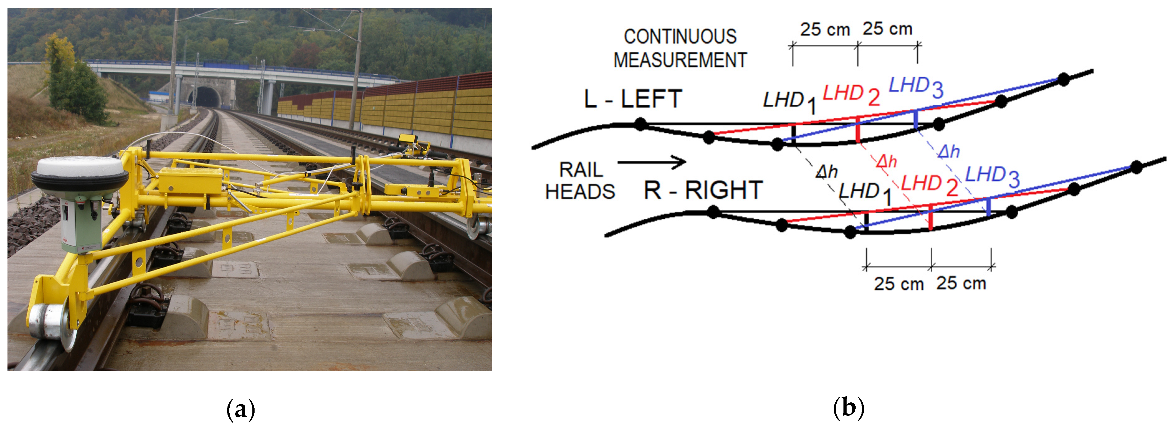
Figure 3.
Detail of LHD monitoring: R – right Dyn_R.
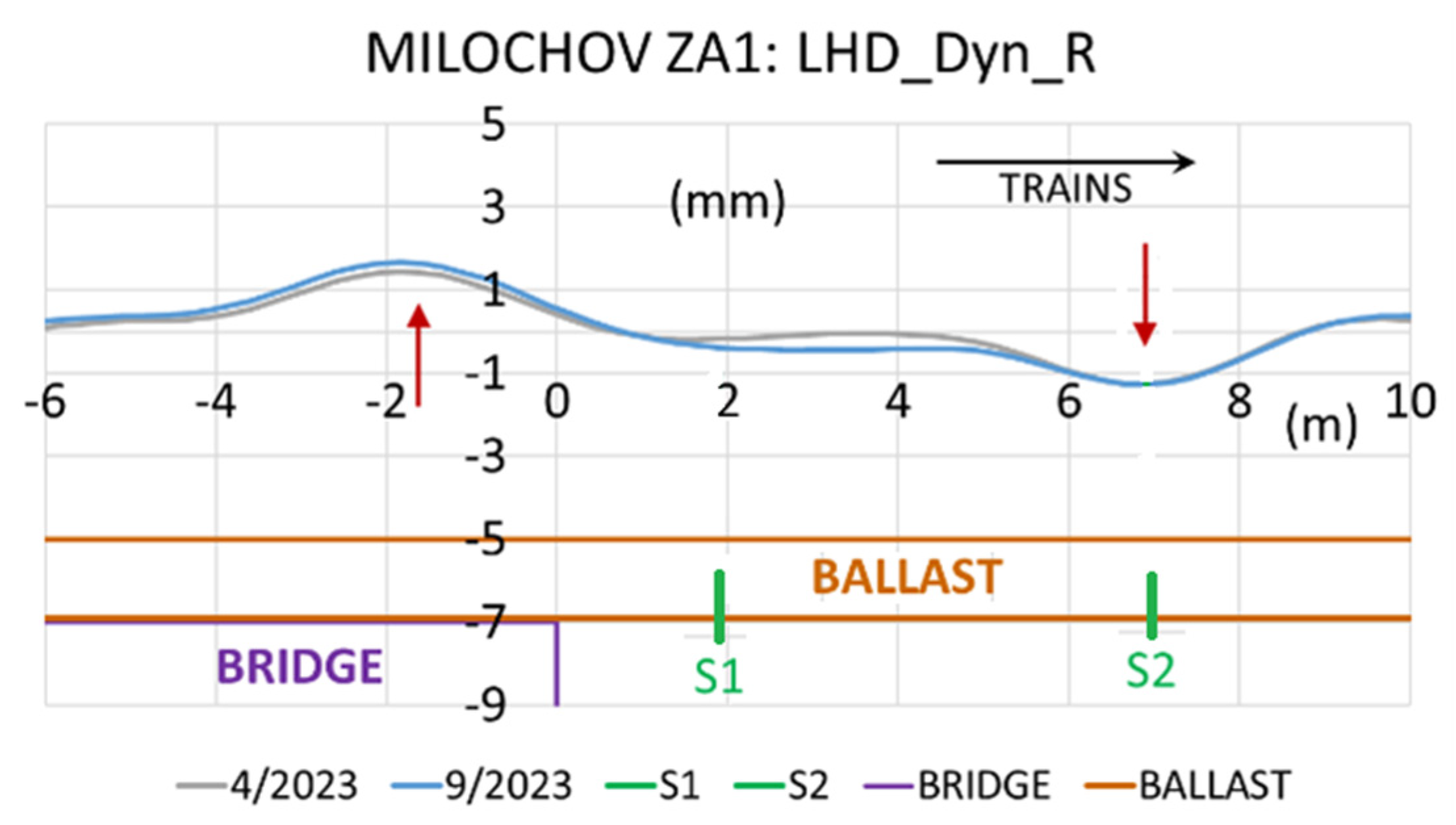
Figure 8.
Monitoring all parameters of the geometric position of the track in the transition zone Milochov: (a) Continuous measurement of KRAB; (b) Continuation.
Figure 8.
Monitoring all parameters of the geometric position of the track in the transition zone Milochov: (a) Continuous measurement of KRAB; (b) Continuation.

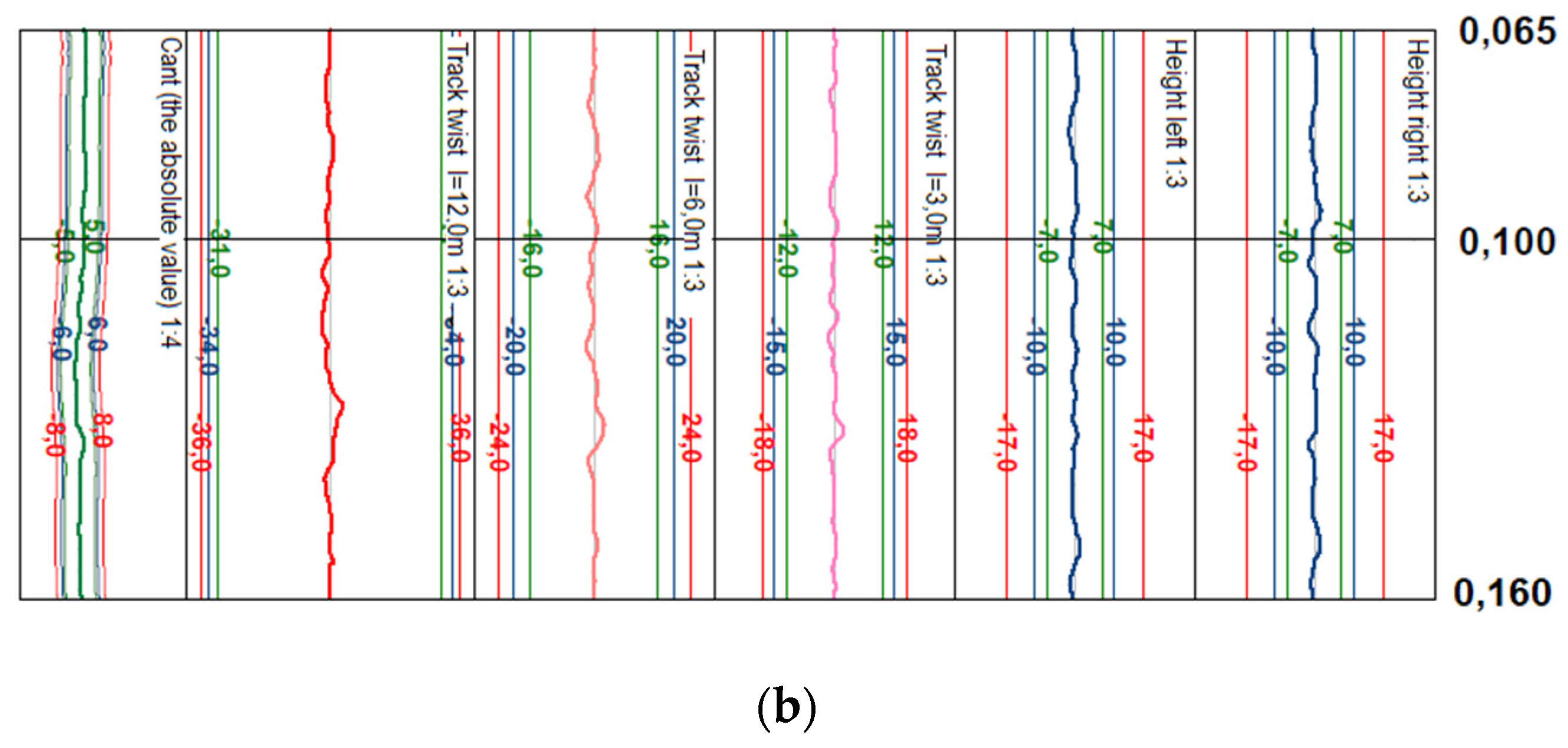
Figure 9.
LHD Height changes - Milochov tunnel portal, track. No. 1– after starting operation: (a) L – left Dyn_L; (b) R – right Dyn_R.
Figure 9.
LHD Height changes - Milochov tunnel portal, track. No. 1– after starting operation: (a) L – left Dyn_L; (b) R – right Dyn_R.
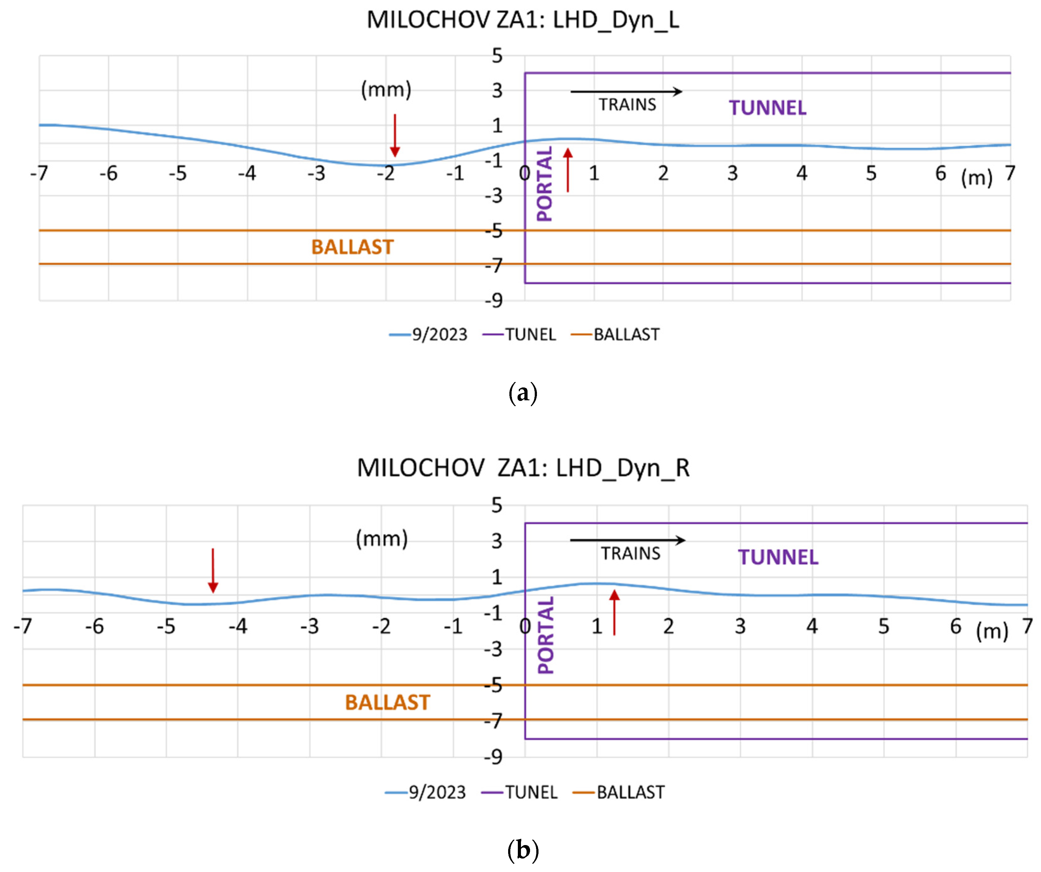
Figure 10.
Overall development of height changes deformations - portal of Trencianske Bohuslavice tunnel, track No. 1 and No. 2 with FRT: (a) ZA2: Dyn_L; (b) BA1 (reversed): Dyn_L.
Figure 10.
Overall development of height changes deformations - portal of Trencianske Bohuslavice tunnel, track No. 1 and No. 2 with FRT: (a) ZA2: Dyn_L; (b) BA1 (reversed): Dyn_L.
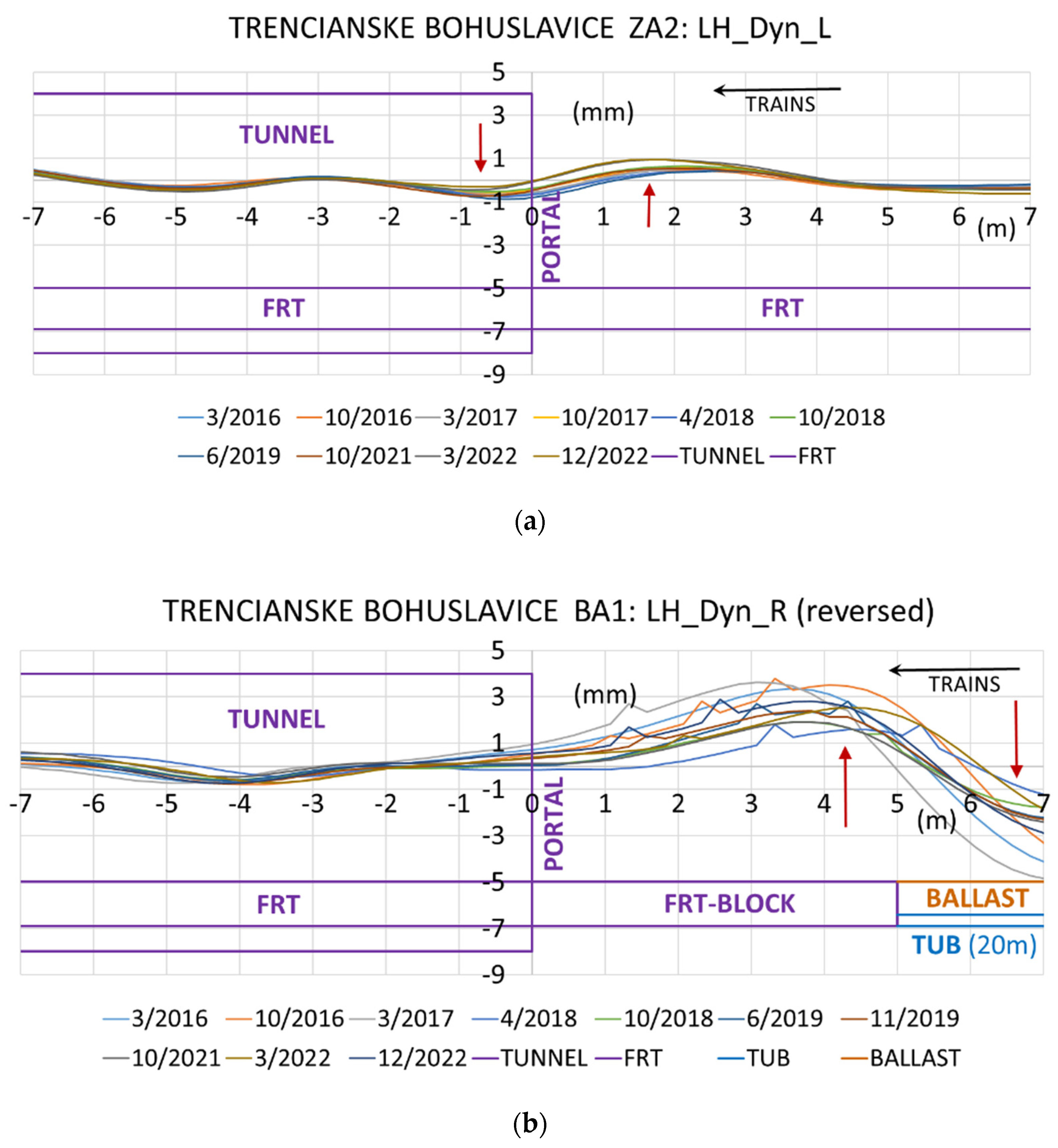
Figure 11.
Characteristic influences in transition zones: (a) Cut; (b) Rise and fall; (c) Double-jump; (d) Ballasted track-waviness by tamping machines.
Figure 11.
Characteristic influences in transition zones: (a) Cut; (b) Rise and fall; (c) Double-jump; (d) Ballasted track-waviness by tamping machines.
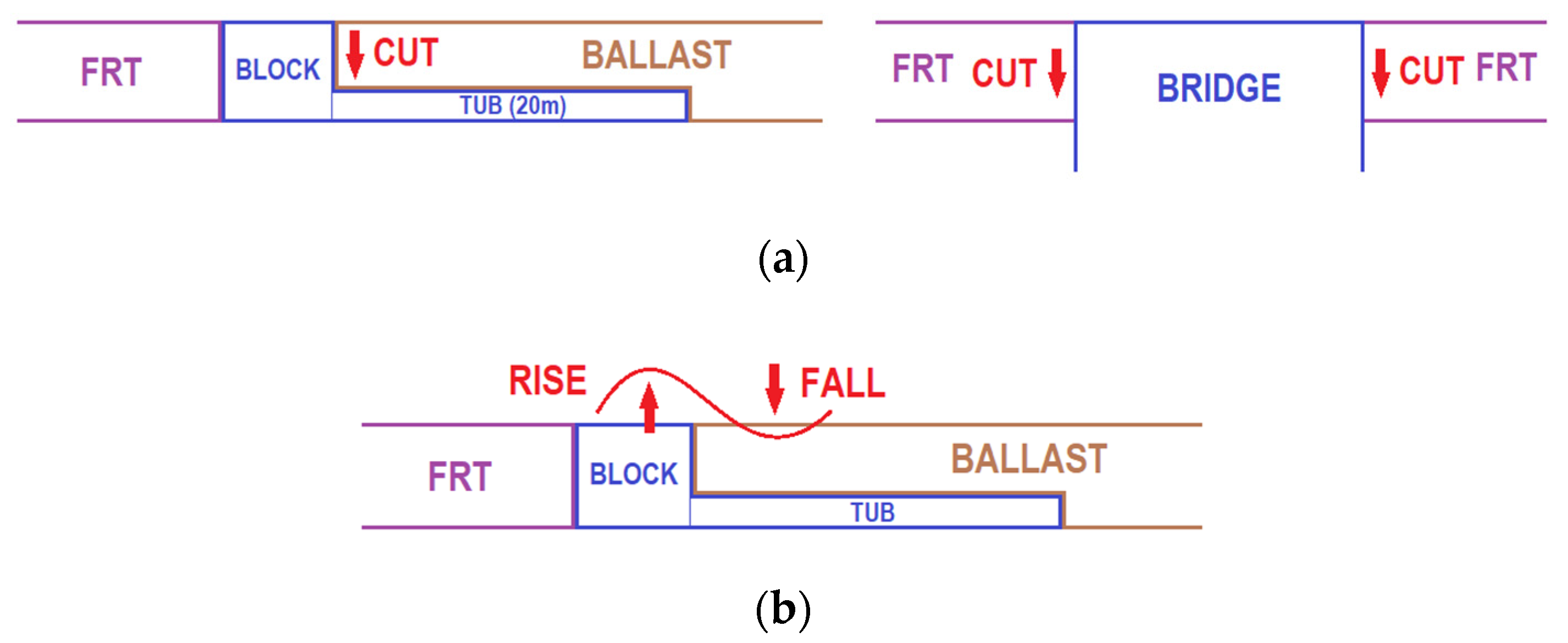
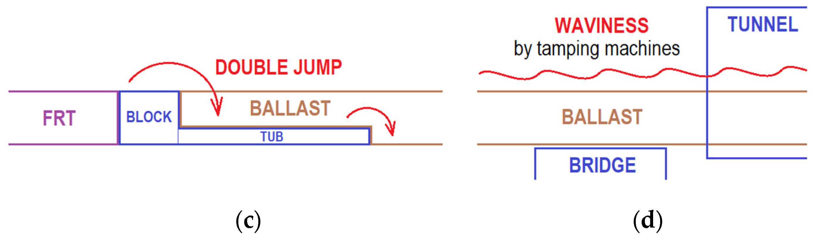
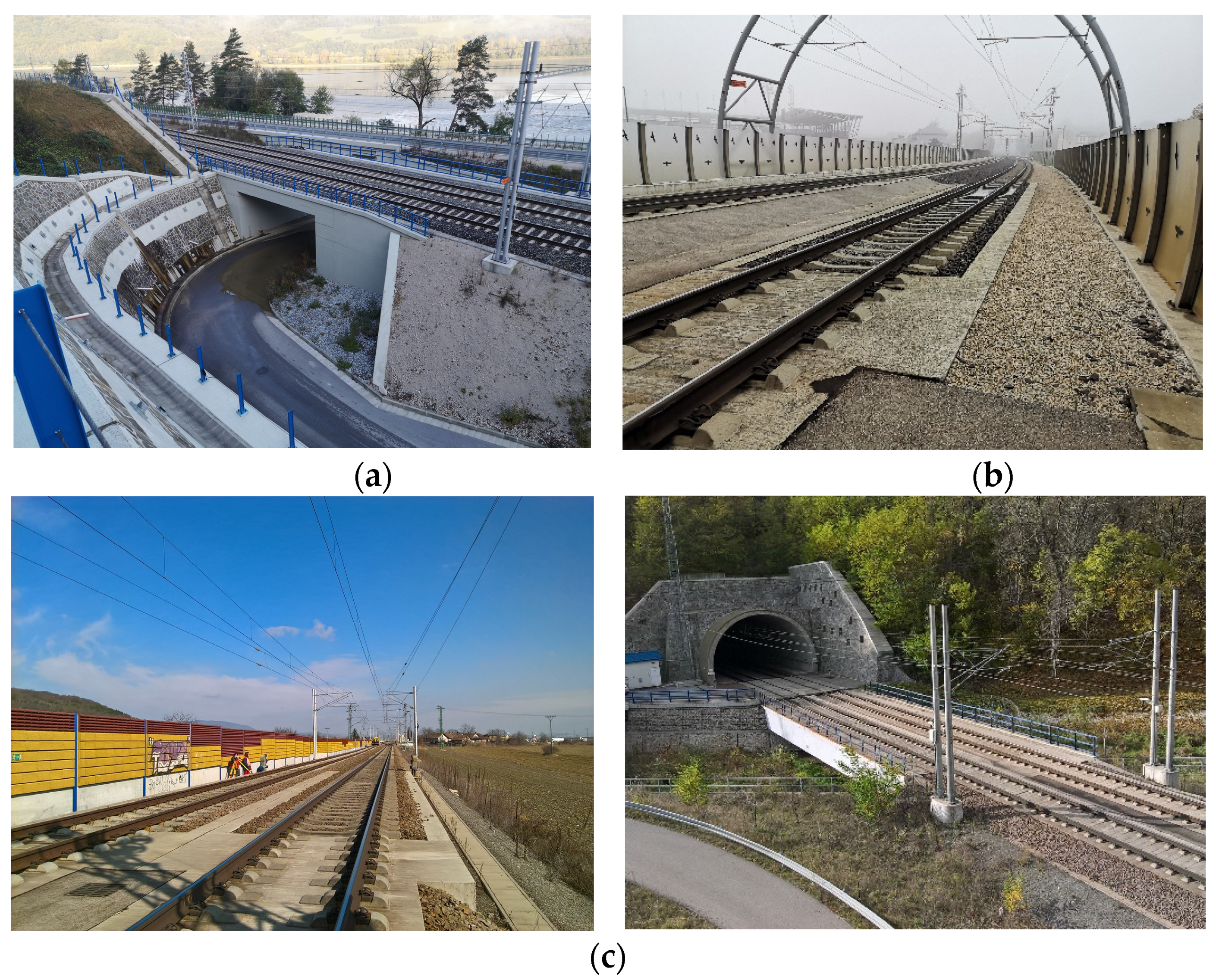
Figure 12.
Photos from research sections of transition zones [Photos: S. Hodas] - cities: (a) Milochov; (b) Trencin; (c) Trencianske Bohuslavice.
Figure 12.
Photos from research sections of transition zones [Photos: S. Hodas] - cities: (a) Milochov; (b) Trencin; (c) Trencianske Bohuslavice.
Disclaimer/Publisher’s Note: The statements, opinions and data contained in all publications are solely those of the individual author(s) and contributor(s) and not of MDPI and/or the editor(s). MDPI and/or the editor(s) disclaim responsibility for any injury to people or property resulting from any ideas, methods, instructions or products referred to in the content. |
© 2025 by the authors. Licensee MDPI, Basel, Switzerland. This article is an open access article distributed under the terms and conditions of the Creative Commons Attribution (CC BY) license (http://creativecommons.org/licenses/by/4.0/).
Copyright: This open access article is published under a Creative Commons CC BY 4.0 license, which permit the free download, distribution, and reuse, provided that the author and preprint are cited in any reuse.


