
Submitted:
04 September 2024
Posted:
05 September 2024
You are already at the latest version
Abstract
Introductory courses regarding radar technologies are very popular in undergraduate curriculum of many electrical and electronics engineering departments. Hands-on experience is an essential part for understanding the theoretical concepts given in lectures. In most cases, it is not affordable for universities to acquire experimental radar systems, especially those in developing countries. This paper presents a detailed description of a cost-effective easy-to-deploy radar system laboratory sessions and measures the educational effectiveness of the proposed material. The provided radar models can be used in teaching undergraduate students the working principles of frequency modulated continuous wave (FMCW) radar systems, as well as assisting graduate students in their research activities. The effectiveness of the laboratory sessions is measured thoroughly via qualitative and quantitative methods based on the proposed learning process and students’ success. The results show that the lab sessions have increased the students' understanding of the topics covered within the course, and the students' general perception is positive.
Keywords:
educational technology
; engineering education
; frequency modulated continuous wave
; radar systems
1. Introduction
A variety of research has been conducted in the field of engineering education for years. New educational methods are developing rapidly due to the fast enhancements in technology which provide new means of teaching/learning techniques [1,2]. Improving the effectiveness of education in the faculty of engineering is a critical concern, considering the difficulty of self-learning and the requirement of complex computational skills [3]. There are several applications that can improve and assist traditional teaching methods [4]. Project-based learning methods, computer-based simulation tools, and hands-on laboratory sessions are examples of such applications [5,6].
Introductory courses in radar technologies are needed in the undergraduate curriculum to deepen the students’ knowledge and to be able to apply it to practical engineering applications (e.g., advanced driver assistance systems, autonomous driving, industrial application, and several defense usages) [7]. After many years of teaching, we found out that the main problem is that the students have difficulties in implementing the learned theoretical concepts of radar systems into real-life applications. To illustrate, interpreting the radar baseband signals and reasoning the use of Fourier transform to transfer the echoed signal into range calculations are examples of such concepts that undergraduate students have difficulties understanding. Thus, laboratory sessions that are structured according to the in-class lectures are needed.
A laboratory model of five training sessions was proposed in [7]. The sessions demonstrate the use of monopulse tracking systems and their use cases in engineering applications. An experimental setup based on the use of commodity WiFi hardware, two commercial panel antennas, and MATLAB signal processing package was presented in [8] to teach amplitude monopulse radar models. In [9], hands-on learning modules were proposed for teaching weather radar applications. The learning modules provide theoretical and practical understanding by allowing students to visualize and analyze weather data. A frequency modulated continuous wave (FMCW) based Synthetic Aperture Radar (SAR) lab model was developed in [10]. Two simple SAR methods were applied on the data obtained from a 24 GHz FMCW radar implemented on a linear drive for educational purposes in [11], and a similar model based on the use of a Vector Network Analyzer was proposed in [12]. In [13], the material described the development and testing of low-cost Inverse Synthetic Aperture Radar (ISAR) turn table system having a machine learning back-end. These radar lab models were found to be very useful for both undergraduate and graduate students in their research activities. Also, an X-band lab model of SAR was given in [14]; however, most of the used components in those proposed models are not commercially available.
A firmware program was given in [15] regarding an interactive control of an FMCW ground-penetrating radar (GPR). Students were able to realize control functionalities; for example, selecting the signal period, frequency range, and waveform type of the transmitted signal. Similar methods were proposed in [16,17], in which students built their own radar systems from provided kits of off-the-shelf components and made use of simulation environments to understand the operational concepts of FMCW radars. In [18], the authors presented a phased array, multiple-input, multiple-output radar system built for educational uses. Students were able to build and test those radar systems. A set of RF and Microwave modules that may be accumulated into a short-range modulated scattered radar system was given in [19]. The module blocks were used by students in the senior and graduate level curriculum.
An approach to replace laboratory experiments with virtual sessions that take advantage of the development of computers and electromagnetic modeling software was given in [20]. An Android-based electronic module application having an intuitive graphical user interface was proposed in [21] for science, technology, engineering, and mathematics (STEM) education. The application was used to teach advanced signal processing systems such as Radar, Lidar, and Sonar. The application provided students the ability to determine distances to objects by allowing them to virtually manipulate several signal shapes, signal envelopes, and frequency constraints. In [22], employing a systematic literature review methodology, the necessity of a virtual electronics laboratory to enhance students’ learning process is investigated. Along with several research questions, the need for an aeronautical radar simulator to increase the efficiency of learning in education is pointed out. Simulation based experiments are very useful, as they can provide understanding of the physics phenomena’s that could be difficult to understand when using a lab-bench approach.
Although the simulation-based experiments are attractive due to the mentioned advantages, they cannot replace the hands-on experience of building real radar systems and performing real-time advanced measurements to fully understand the operation concepts of those systems [20]. Different from many examples of hands-on radar laboratory sessions that can be found in literature such as in [7,8,23,24,25], which rely on extensive and expensive projects, the proposed radar models used for the lab sessions in this paper are cost-effective, easy to deploy and operate.
The contributions of this study are as follows: it presents a full laboratory module for undergraduate radar systems courses, consisting of ten laboratory sessions which are structured based on the lecture topics. The proposed laboratory structure includes iterative design of modular radar system as well as fully operational commercial radar platform. As none of the reported literature on this topic evaluated the impact of the proposed educational material on the students’ success, the measurement results of this paper are believed to be the first to provide both quantitative and qualitative assessments of the proposed teaching method.
The rest of the paper is organized as follows: In section 2, the proposed laboratory sessions are described. The quantitative and qualitative measurement methods regarding the effectiveness of the developed materials are described in detail in section 3 presents. In section 4, we provide the results of the assessments. Finally, section 4, draws conclusions and points out potential future works.
2. Materials and Methods
In this section, we provide a detailed description of the two different radar system setups that have been used in the laboratory sessions, followed by an explanation of the objectives and the methods used for each session.
2.1. Experimental Setups
Laboratory sessions based on FMCW radar systems are examples of real-world applications, invested in extensive physical and mathematical contents. Different from conventional radar systems that operate in the time domain, FMCW radars operate in the frequency domain. Therefore, spectral and phase analyses are needed to determine the range and velocity of a variety of targets. Thus, to proceed with the laboratory sessions, students are introduced to signal processing topics such as Fourier transform, sampling as well as amplifiers and filters. In the proposed laboratory structure, two different types of FMCW radars were used; the first one is a fully modular system operating at 4.4-4.9 GHz band (Radar-I) and the second is a commercial radar platform operating at 77-81 GHz band (Radar-II). The former is intended to develop module/component level RF design of a radar system while the latter aims to develop signal analysis, functionality as well as operational aspects of a radar system.
2.1.1. Radar-I
A low-cost modular FMCW radar system has been developed in our university Radio Research Laboratory (RRL) for research and educational purposes [26]. The modular FMCW radar was implemented using a voltage control oscillator (VCO) for signal generation, and a DC power supply used for arranging the offset voltage. Also, a splitter, a mixer, a low pass filter (LPF), and a low noise amplifier (LNA), along with a power amplifier were used in the prototype. Operational testing has been done in the university laboratory, using metal plates as targets. The received signals are analyzed by using a spectrum analyzer (SA). Radar-I has a bandwidth of 525 MHz, and a 30 cm range resolution. In Figure 1, the prototype of the radar is shown along with the manufacturer code numbers.
2.1.2. Radar-II
A commercial-of-the-shelf (COTS) millimeter wave (mmWave) FMCW radar system, has been used as the second type of radar in the proposed laboratory sessions. The radar platform consists of an AWR1642BOOST evaluation module which has two transmit and four receive PCB antennas, also a DCA1000EVM data capture card that is connected to the PC for post-processing using the mmWave Studio program. The radar system operates with 4 GHz available bandwidth, allowing users to employ different applications, i.e., Radar cross section (RCS), measurements, range, velocity, and angle estimations. In Figure 2, the functional block diagram of AWR1642 is shown. As shown in the figure, the individual modules used in the Radar-I are compactly contained in the Radar-II which allows students to acknowledge different types of radar setups.
2.2. Laboratory Sessions
In the laboratory sessions, two types of radar systems described previously, and their modular components are used for teaching. While Radar-I is used in conducting sessions from 1 to 8, Radar-II is used in conducting sessions 9 and 10. Students are first introduced to each of the modular components, which were used to build the FMCW radar, as described in sessions from 1 to 5. Later, understanding the use of the complete radar system and performing experimental measurements are done in sessions from 6 to 8. The last two experiments (9-10) introduce the compact commercial off-the-shelf radar version of the previous experiments. Laboratory experiments and course videos have been shared online [28]. In this way, it has become easier for students to easily access course and laboratory contents The details of the lab session are as follows:
- FMCW radar waveform generation; Understanding the operation of Voltage Control Oscillator (VCO), FMCW signal generation using VCO, and experimental analysis of FMCW signals in the frequency domain are performed in this lab session. VCO is connected to the DC voltage supply and an analog wave generator. These are adjusted to tune the frequency in the range of 4200 MHz to 4600 MHz. The output is connected to a SA to see the generated FMCW signal in the frequency domain.
- Up/Down conversion; Understanding frequency mixing in FMCW Radar systems, and experimental analysis of the use of the mixer for down conversion are given in this lab session. The original signal to be down-converted is at 4272-4600 MHz band. The aim is to obtain a down-converted signal at a frequency over 272-600 MHz. The original signal is transmitted using the VCO and applied to the RF input port of the Mixer. A signal generator is used to transmit a signal of frequency 4000 MHz to the LO input port of the Mixer. The output (IF port of the Mixer) is connected to a SA in order to observe the down converted signal spectrum.
-
Amplification and attenuation; Experimental analysis of Power Amplifiers (PA) and Low Noise Amplifiers (LNA) for use in FMCW radar systems and understanding of amplification and attenuation of RF signals are implemented in this lab session. The experimental setups are given in Figure 3. The experiment is conducted in two parts using PA and LNA, separately.Experimental setups are set up to observe the power of the signal. This process is repeated for different bandwidths and for different attenuator values (e.g., 3 dB, 10 dB, and 15 dB).
- 4.
- Signal mixing and filtering; Analysis of the use of the combination of a mixer and a LPF in FMCW radar systems is performed in this lab session. By repeating the procedures in Experiment 2, an IF signal is obtained at the mixer output. The presence of harmonics beyond the desired wideband down-converted signal (270-783 MHz) is interpreted. On the other hand, the output of the mixer is connected to LPF. Results are compared using SA to understand the effect of the LPF.
- 5.
-
Antennas, connectors, and cabling; Basic concepts regarding antenna gain and connectors/cabling loss are covered in this lab session, as well as analysis of the radio link in terms of link budget. The experimental setup of this experiment is given in Figure 4.In this experiment, the received signal power is going to be recorded from the SA for different separation distances between the two antennas, as well as for different frequency bands. Finally, the theoretical values of the received signal power are compared with the experimental values. The difference margins between the theoretical and experimental results are discussed and analyzed.
- 6.
- Modular transmitter design; The modular transmitter design used for the FMCW radar system is explained in this lab session. Furthermore, the experimental analysis regarding determining the radar range is performed. Using the recorded received signal on the SA at different distances, the link budget equation is written and all the losses (cable, connectors, channel, etc.) are estimated. The bandwidth of the FMCW signal is determined such that the range resolution is 30 cm. The range resolution formula is given as where B is the bandwidth of the signal and, c is the speed of the light. The maximum distance between the Tx and Rx has been estimated such that the peak power to noise power level is higher than 25 dB.
- 7.
-
Modular receiver design; The modular receiver design used for the FMCW radar system is given in this lab session. Additionally, determining the RCS of a reflector plate is measured by performing an experimental demonstration to the students. The experimental setup is given in Figure 5.The FMCW radar used in this experiment is a monostatic radar system. In this experiment, the received signal power is recorded from the SA for different separation distances between the radar and the target. Using the radar range equation formula given in (1), the RCS (σ) of the target at every distance of observation is estimated.where refers to the distance that the received power is measured at, is the recorded received power from the SA, is the transmitted power, is the gain of each antenna, and λ is the wavelength at the desired frequency.
- 8.
- Modular radar design: This lab session focuses on explaining the complete modular FMCW radar design given in Figure 1, as well as performing several experimental analyses for determining the range of targets. The target used in the monostatic radar system is a metallic plate (reflector plate) to be placed at four different ranges. The measurement of the beat frequency, which gives the range information is recorded from the SA and is compared with the theoretical value. Also, the presence of frequency offset due to the cables and connectors is discussed. In the later equation, is the modulation bandwidth and is the period of triangular signal (modulation period) [29].
- 9.
- Introduction to TI mmWave Radar Platform; Understanding of the TI mmWave radar platform [30], its hardware components, and the radar parameters that affect the practical RCS measurement of a target are discussed in this lab session. The combination of the AWR1642 radar module and the DCA1000 data capture is used. The platform transmits an FMCW signal via two transmitters and it receives back the echoed signal via four separate receiving channels. The received signal is presented in the form of complex I/Q at Intermediate Frequency (IF) band. The signal is transferred to a computer and the processed data is acquired using the mmWave studio program. The settings and calculations of the radar parameters and their association with each other are discussed, and the measurement of the target RCS is performed.
- 10.
- TI mmWave radar platform; Understanding the configuration parameters of an FMCW radar according to the maximum range, best range resolution scenarios, and RCS measurements of different objects are demonstrated in this session. With the calculation of the chirp signal parameters, several experiments based on different scenarios are conducted. Measurements of targets at different distances are conducted considering the maximum range equation given in (3) and the measurement of the range resolution is also performed to see the ability of distinguishing two objects close to each other.where is the Analog Digital Converter (ADC) sampling frequency and is the slope of the transmitted chirp. Finally, the relationship between the maximum range and the range resolution is considered based on the theoretical formulas.
At each of the lab sessions, a detailed repetition of the theoretical foundations which were given in the course lectures is given to the students. These are followed by practical exercises and in-lab quizzes which the students must work on. Finally, a short oral quiz is given toward the end of the lab sessions to determine the students' understanding of the topic. Additionally, students’ perceptions of the contribution of the lab experiments are evaluated based on interviews and anonymous surveys.
2.3. Assessment Methods
The effectiveness measurement of the proposed laboratory activities is conducted using several qualitative and quantitative assessments, including face-to-face interviews, anonymous surveys, quizzes, along with the course exam results. Figure 6 represents the flowchart of the material preparation and assessment process. After the feedback from the assessments is collected and analyzed, deficiencies in the proposed laboratory activities are corrected and the material is improved. When the material is completed, the results are presented, and the process is finalized.
2.3.1. Interviews
At the beginning and middle of the semester, two different face-to-face interviews were done with the students. Interviews were conducted based on the contribution of the laboratory sessions to the students' learning process and how their perceptions changed during the course.
2.3.2. Anonymous Surveys
A total of three anonymous surveys containing both a five-point Likert scale and open-ended questions were conducted at the beginning, middle, and end of the semester (Survey-1, Survey-2, and Survey-3, respectively). Survey-1 was an introductory survey aiming to analyze the educational background and general skills of the students. It included questions about gender, age, cumulative GPA, knowledge/background about probability and random processes, communication systems, and signals and systems courses. Additionally, the evaluation of the ability to use laboratory equipment such as a SA, waveform generator, and oscilloscope was asked. Finally, opinions about the contribution of the laboratory sessions to their learning process and the purpose/expectation of taking the radar systems course were noted. Survey-2 and 3 aimed at obtaining information regarding the students’ progress during the semester. Questions were asked aiming to observe the quality of the proposed educational method and its contribution to the learning process.
2.3.3. Laboratory Quizzes
An online pre-quiz was given to encourage students to study for the experiment before coming to the laboratory sessions. In the lab, two quizzes were done, one of them being before the experiment (pre-test) and the other after (post-test). This is done to continuously measure the contribution of the laboratory activities to the student’s learning process. In addition, during the experiments, it was ensured that the students participated in the experiments and reinforced the subject with short oral questions.
3. Results and Discussion
A comprehensive analysis of the qualitative and quantitative assessments including face-to-face interviews, anonymous surveys, and achievements on both the quizzes and exams are conducted.
3.1. Interviews
The first interview was applied after the second experiment. In the first interview, students were asked to evaluate the workload of the course, the provided course materials, and resources, as well as their perceptions regarding the first two experiments. Additionally, it was asked what the pros and cons of the proposed applied course material were, and how they related the experiments with the theory covered in the lectures. Most of them stated that the workload is a bit heavy compared to the other technical elective courses, yet they stated that their understanding of the course is much better. Most of the students found that the provided course materials were sufficient and helpful enough. The common expectation from the laboratory activities is to learn the working principles of radars and to have knowledge of designing and operating radars in a simple way. As a matter of fact, it was the black spot of the lecture and the motivation of the authors. Also, they stated that the lab manuals were instructive and helped them in their learning process. They stated that the lab quizzes encouraged them not to drift away from the course and to study continuously. They agreed that the first two lab experiments formed the basis of the first lectures and the laboratories helped them to visualize their theoretical background. Moreover, they added that the relation between the mathematical equations and the practical applications had become clearer. They stated that they have obtained hands-on experience on how to use an oscilloscope, signal generator, waveform generator, and SA. After the second laboratory session, they stated that they completely understand the concept of up/down conversion which they had been taught in several different courses before.
The second interview was conducted after the sixth experiment. In the second interview, the workload was asked again. It was found that the students do not think that the workload is heavy for them anymore. They emphasized once again that they found the provided course resources sufficient. They stated again that the logic of the lessons was understood together with the experiments. They confirmed that the experiments are understandable, and the content is adequate and supplementary. Also, they highlighted that the laboratory activities are strongly related to the lectures and had a great impact on the learning process. Observing each component individually, and then combining them to obtain a fully operating radar system is what the students found to be the best about the laboratory activities.
3.2. Anonymous Surveys
In the first survey, the average CGPA of the class was found as 3,15. The average letter grade of the probability and random processes course, and communication systems course was BB. Students are asked to score the course materials on a five-point Likert scale (1: absolute insufficient, 5: absolute sufficient), the average result was found as 4,1. The ability to use the hardware laboratory equipment was asked again as in interviews, all of the students indicated that they know how to use them. The general contribution of other courses’ laboratories in the past 4 years to the students’ learning process is asked and 66% of the class graded this question as 5. It can be said that students’ opinion about the general laboratory activities is quite positive. Students’ expectations from the radar systems course is asked. The following comments were reported by some of the students:
- “I enjoyed the signals and systems and the communication systems courses. So, I believe I will be successful in the radar systems course.”
- “I want to gain knowledge about radar systems and perform a simple radar design.”
- “I am currently interested in the RCS applications. I think this course will be helpful for this.”
- “I want a career in which I can advance in the defense industry in the future.”
In the second survey, the content of the course and the laboratory were investigated individually. The list of the items asked in the survey and the mean values of each item are presented in Table 1. All the students attended the lectures and the experiments regularly. From Table 1, we can say that they were quite satisfied with the content and the materials of the course. Similar questions were asked in both the course and experiment assessments to observe the consistency of the scores. Students gave the lowest score on the face-to-face quizzes for both the course and the laboratory which is understandable since they are more challenging than online quizzes. Also, students found that the contribution of the experiments to their learning process was notably sufficient. The ability to relate the theory to the experiments was asked both in the course and the experiment assessments. A large majority of the students graded that item as 5 with reasonable consistency. Their overall comments were also asked in the survey. While some of them criticized taking pre- and post-quizzes every week, a large majority of them found that the quizzes were helpful, and they stated that they came prepared for the lectures and experiments and it made the topic more understandable for them.
The questions asked in the final survey and the mean values of each question (out of 5) are given in Table 2. After the low grading of face-to-face post-tests in Survey-2, the students were asked regarding it, and it has been observed that the score given to this item has increased both for the course and the laboratory activities. The score of the contribution of the laboratory activities to the students’ learning process showed consistency with Survey-2. However, when the difficulty of the course and the experiments were asked, the average score showed up as equal. From these results, we can say that the hands-on experiments were quite effective in terms of the contribution to the students learning of the radar systems course, especially in the introductory levels. When their perception about whether they have obtained enough knowledge about the radar systems was asked, a decrease is observed in the average score compared to Survey-2. The final answers can be considered more realistic as they learn more, they realize there is more to learn.
3.3. Laboratory Quizzes
It is aimed to evaluate the performance of the new educational method by comparing the GPA of the students in the last three terms. When the average of the students' grades is observed in the 3rd term, during which the proposed laboratory activities were applied, a significant increase is observed as can be seen from Table 3. It should be noted that the difficulty level, content, and types of questions on the exams of the course were the same for all 3 terms. In the 1st and 2nd terms, only Radar-I was used in the experiments, while in the 3rd term, by adding Radar-II, students had the chance to work on different radar modules. In the first term’s laboratory, 5 experiments which are a combination of the first 8 experiments mentioned earlier were conducted. In the last term, the full 10 laboratory activities were carried out. For each experiment, both the online and in-class pre-tests along with in-class post-tests were given to the students. The average grade for the laboratory online pre-tests is 85,8 and for the in-class pre-tests was 71,9. Although the control of the students is a challenging issue in online exams, no significant difference is observed between the online and in-class quizzes. The average grade of the post-tests applied after each laboratory activity was 79,9. We observed that most of the class came to the laboratories prepared, and they followed the experiments during the session. Also, a question-based assessment was conducted for the laboratory quizzes. It was seen that the average score of the class regarding the questions that evaluate the ability to relate theory to practice was 81,1. In the first 5 experiments, the main components of a radar system such as VCO, mixer, LPF, antennas, connectors, and cables were introduced, and their operation principles were discussed. At each laboratory session, a new component was added to the system and its output was observed. The total average of the exam results regarding these experiments is 84,4. In the following three experiments, all the individual components are combined, and a modular structure of the transmitter and the receiver is obtained. Various radar ranges, RCS, and link budget experiments are conducted. The total average exam result regarding these experiments is 74,06. A decrease is observed according to the first five experiments since the students are expected to use their theoretical knowledge more as the content of the course develops further. The last two experiments cover a COTS ready-to-use radar in a compact form. This radar platform was quite different from what they have worked on so far in terms of principle and platform. However, the total average of the exam results regarding these experiments was 73,93 not so different than the previous average. Thus, it was observed that students were able to adapt very easily and learn the working logic faster when they encountered different radar types.
4. Conclusions
In this paper, a laboratory for the radar systems course and a methodology for measuring its effectiveness are presented. Ten radar lab sessions are designed to give a comprehensive understanding of the theoretical topics covered in the course. By understanding the radar components one by one in each session, the theoretical knowledge of the students based on radar systems is examined experimentally. Students gain experience in radar design and operation when the final system is shown. Then, with a different radar structure, students showed their ability to adapt by using their previous hands-on experience. To measure the effectiveness of these laboratory activities in the students’ learning, both qualitative and quantitative assessments are employed. Considering the assessments, the proposed applied course material has affected the students’ success level positively. In addition, the perception of the students regarding the lab structure and material was found satisfactory. To the best of the authors' knowledge, this is the first study that measures the educational effectiveness of an applied educational method for radar systems course.
Author Contributions
Conceptualization, B.Y.G. and R.B.C.; methodology, B.Y.G.; validation, M.B., and A.K.; formal analysis, B.Y.G., M.B.; investigation, M.B, and R.B.C.; writing—original draft preparation, B.Y.G., M.B., R.B.C.; writing—review and editing, A.K.; visualization, R.B.C.; supervision, A.K. All authors have read and agreed to the published version of the manuscript.
Funding
This research received no external funding.
Institutional Review Board Statement
Not applicable.
Informed Consent Statement
Not applicable.
Data Availability Statement
The data supporting the conclusions of this article will be made available by the authors on request.
Conflicts of Interest
The authors declare no conflicts of interest.
References
- Sianez, D. M.; Fugère, M. A.; Lennon, C. A. Technology and engineering education students’ perceptions of hands-on and hands-off activities. Research in Science & Technological Education 2010, 28, 291–299. [Google Scholar]
- Vásquez-Carbonell, M. A Systematic Literature Review of Augmented Reality in Engineering Education: Hardware, Software, Student Motivation & Development Recommendations. Digital Education Review 2022, (41), 249–267. [Google Scholar]
- Wankat, P. C.; Oreovicz, F. S. Teaching prospective engineering faculty how to teach. International Journal of Engineering Education 2005, 21, 925. [Google Scholar]
- Gokdogan, B. Y.; Coruk, R. B.; Benzaghta, M.; Kara, A. A Hybrid-Flipped Classroom Approach: Students’ Perception and Performance Assessment. Ingeniería e Investigación 2023, 43, 16. [Google Scholar] [CrossRef]
- Singh, J.; Perera, V.; Magana, A. J.; Newell, B.; Wei-Kocsis, J.; Seah, Y. Y. .Xie, C. Using machine learning to predict engineering technology students’ success with computer-aided design. Computer Applications in Engineering Education 2022, 30, 852–862. [Google Scholar] [CrossRef]
- Coruk, R. B.; Yalcinkaya, B.; Kara, A. On the design and effectiveness of simulink-based educational material for a communication systems course. Computer Applications in Engineering Education 2020, 28, 1641–1651. [Google Scholar] [CrossRef]
- Diewald, A. R.; Wallrath, P.; Müller, S. Five Radar Sessions for University Education. In 2018 48th European Microwave Conference (EuMC) (pp. 456-459). IEEE. September 2018.
- Poveda-García, M.; López-Pastor, J. A.; Gómez-Alcaraz, A.; Martínez-Tamargo, L. M.; Pérez-Buitrago, M.; Martínez-Sala, A.; ... Gómez-Tornero, J. L. Amplitude-monopulse radar lab using WiFi cards. In 2018 48th European Microwave Conference (EuMC) (pp. 464-467). IEEE. September 2018.
- Chilson, P. B.; Yeary, M. B. Hands-on learning modules for interdisciplinary environments: An example with a focus on weather radar applications. IEEE Transactions on Education 2011, 55, 238–247. [Google Scholar] [CrossRef]
- Ali, T.; Burki, J. Design and development of X-band FMCW based lab model of Synthetic Aperture Radar (SAR) for applications in engineering education. In 2016 19th International Multi-Topic Conference (INMIC) (pp. 1-6). IEEE. December 2016.
- Berg, J.; Müller, S.; Diewald, A. R. Far-and Near Range Measurements with a Synthetic Aperture Radar for Educational Purposes and Comparison of Two Different Signal Processing Algorithms. Advances in Radio Science 2022, 19, 221–232. [Google Scholar] [CrossRef]
- Burki, J.; Ali, T.; Arshad, S. Vector network analyzer (VNA) based synthetic aperture radar (SAR) imaging. In INMIC (pp. 207-212). IEEE. December 2013.
- Blomerus, N. D.; Cilliers, J. E.; de Villiers, J. P. Development and testing of a low cost audio based ISAR imaging and machine learning system for radar education. In 2020 IEEE International Radar Conference (RADAR) (pp. 766-771). IEEE. April 2020.
- Charvat, G. L.; Kempel, L. C. Synthetic aperture radar imaging using a unique approach to frequency-modulated continuous-wave radar design. IEEE Antennas and Propagation Magazine 2006, 48, 171–177. [Google Scholar] [CrossRef]
- Chizh, M.; Pietrelli, A.; Ferrara, V.; Zhuravlev, A. Development of embedded and user-side software for interactive setup of a frequency-modulated continuous wave ground penetrating radar dedicated to educational purposes. In 2017 IEEE International Conference on Microwaves, Antennas, Communications and Electronic Systems (COMCAS) (pp. 1-5). IEEE. November 2017.
- Charvat, G. L.; Fenn, A. J.; Perry, B. T. The MIT IAP radar course: Build a small radar system capable of sensing range, Doppler, and synthetic aperture (SAR) imaging. In 2012 IEEE Radar Conference (pp. 0138-0144). IEEE. May 2012.
- Luttamaguzi, J.; Eslami, A.; Brooks, D. M.; Sheybani, E.; Javidi, G.; Gabriel, P. M. Using Simulations and Computational Analyses to Study a Frequency-Modulated Continuous-Wave Radar. International Journal of Interdisciplinary Telecommunications and Networking (IJITN) 2017, 9, 38–51. [Google Scholar] [CrossRef]
- Perry, B. T.; Levy, T.; Bell, P.; Davis, S.; Kolodziej, K.; O'Donoughue, N.; Herd, J. S. Low cost phased array radar for applications in engineering education. In 2013 IEEE International Symposium on Phased Array Systems and Technology (pp. 416-420). IEEE. October 2013.
- Campbell, R. L.; Pejcinovic, B. Project-based RF/microwave education. In 2015 10th European Microwave Integrated Circuits Conference (EuMIC) (pp. 456-459). IEEE. September 2015.
- Hum, S. V.; Okoniewski, M. A low-cost hands-on laboratory for an undergraduate microwave course. IEEE Antennas and Propagation Magazine 2007, 49, 175–184. [Google Scholar] [CrossRef]
- Robistow, B.; Newman, R.; DePue, T. H.; Banavar, M. K.; Barry, D.; Curtis, P.; Spanias, A. Reflections: An eModule for echolocation education. In 2017 IEEE International Conference on Acoustics, Speech and Signal Processing (ICASSP) (pp. 1562-1566). IEEE. March 2017.
- Pereira Júnior, E. L.; Moreira, M. Â. L.; Portella, A. G.; de Azevedo Junior, C. M.; de Araújo Costa, I. P.; Fávero, L. P.; … dos Santos, M. Systematic Literature Review on Virtual Electronics Laboratories in Education: Identifying the Need for an Aeronautical Radar Simulator. Electronics 2023, 12, 2573. [Google Scholar] [CrossRef]
- Bonefacic, D.; Jancula, J. Laboratory model of a monopulse radar tracking system. In Proceedings ELMAR 2006 (pp. 227-230). IEEE. June 2006.
- Bonefačić, D.; Jančula, J.; Majurec, N. Model of a monopulse radar tracking system for student laboratory. Radioengineering 2007, 16, 63. [Google Scholar]
- Saratayon, P.; Pirom, V.; Saelim, T. RSSI monopulse azimuth tracking demonstration using wideband personal area network device. Int. Journal of Engineering Research and Technology 2013, 2, 663–670. [Google Scholar]
- Abdulrazigh, M. Y.; Uzundurukan, E.; Kara, A. Analysis of measurement instrumentation delay in modular experimental radar at C band. In 2018 26th Signal Processing and Communications Applications Conference (SIU) (pp. 1-4). IEEE. May 2018.
- Instruments, T. Awr1642 single-chip 77-and 79-ghz fmcw radar sensor. Datasheet AWR1642 2017, Rev, 60.
- 2020 Radar Systems (Atılım) [Video list]. YouTube. Available online: https://youtu.be/ImRsq5WwrhM?si=sA4b2Oq86yuGdSNs (accessed on 27 February 2024).
- Mahafza, B. R. Introduction to radar analysis. CRC press, 2017.
- Dham, V. Programming chirp parameters in TI radar devices. Application Report SWRA553, Texas Instruments 2017, 1457.
Figure 1.
Radar-I Modular FMCW radar system.
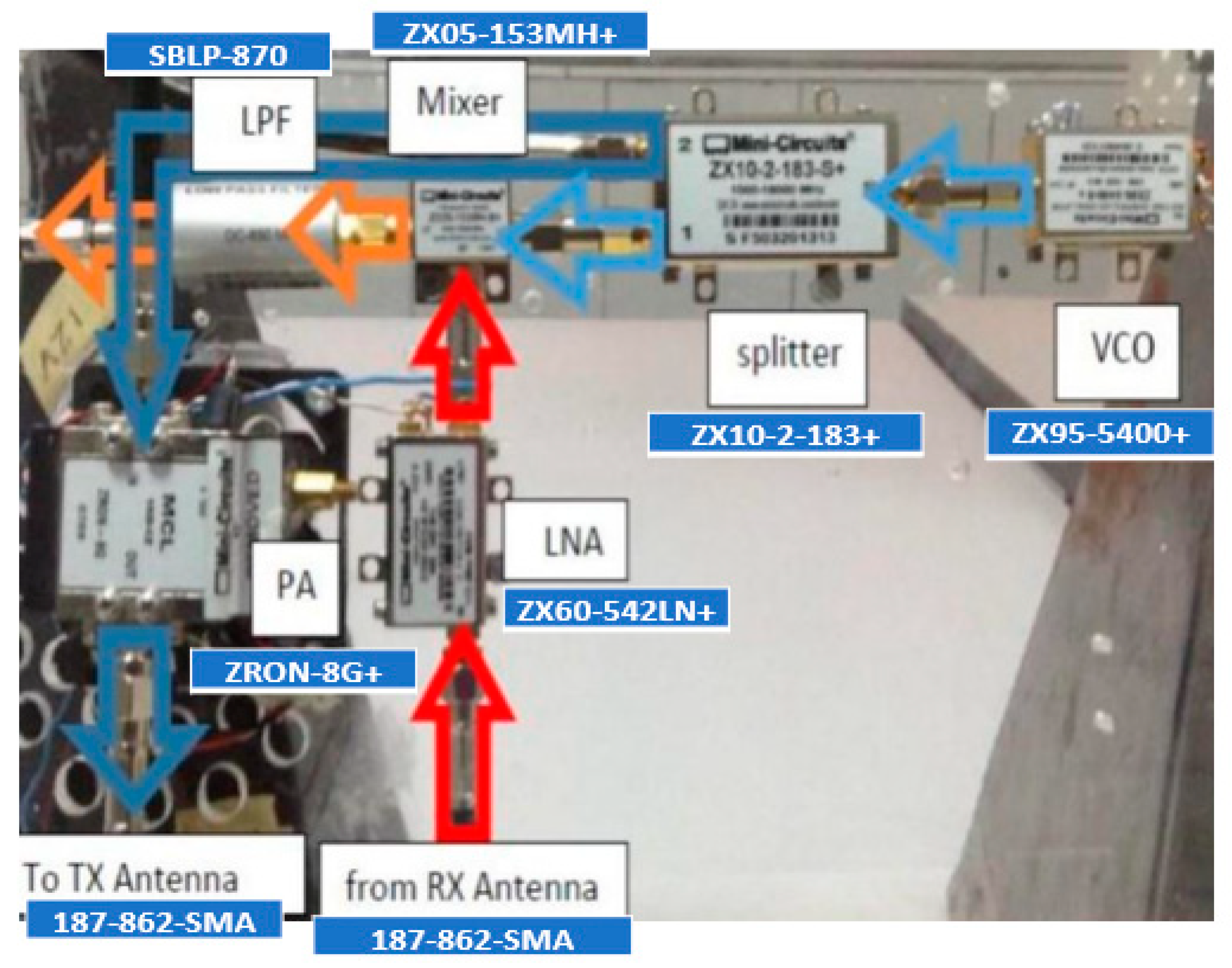
Figure 2.
Functional Block Diagram of Radar-II [27].
Figure 2.
Functional Block Diagram of Radar-II [27].
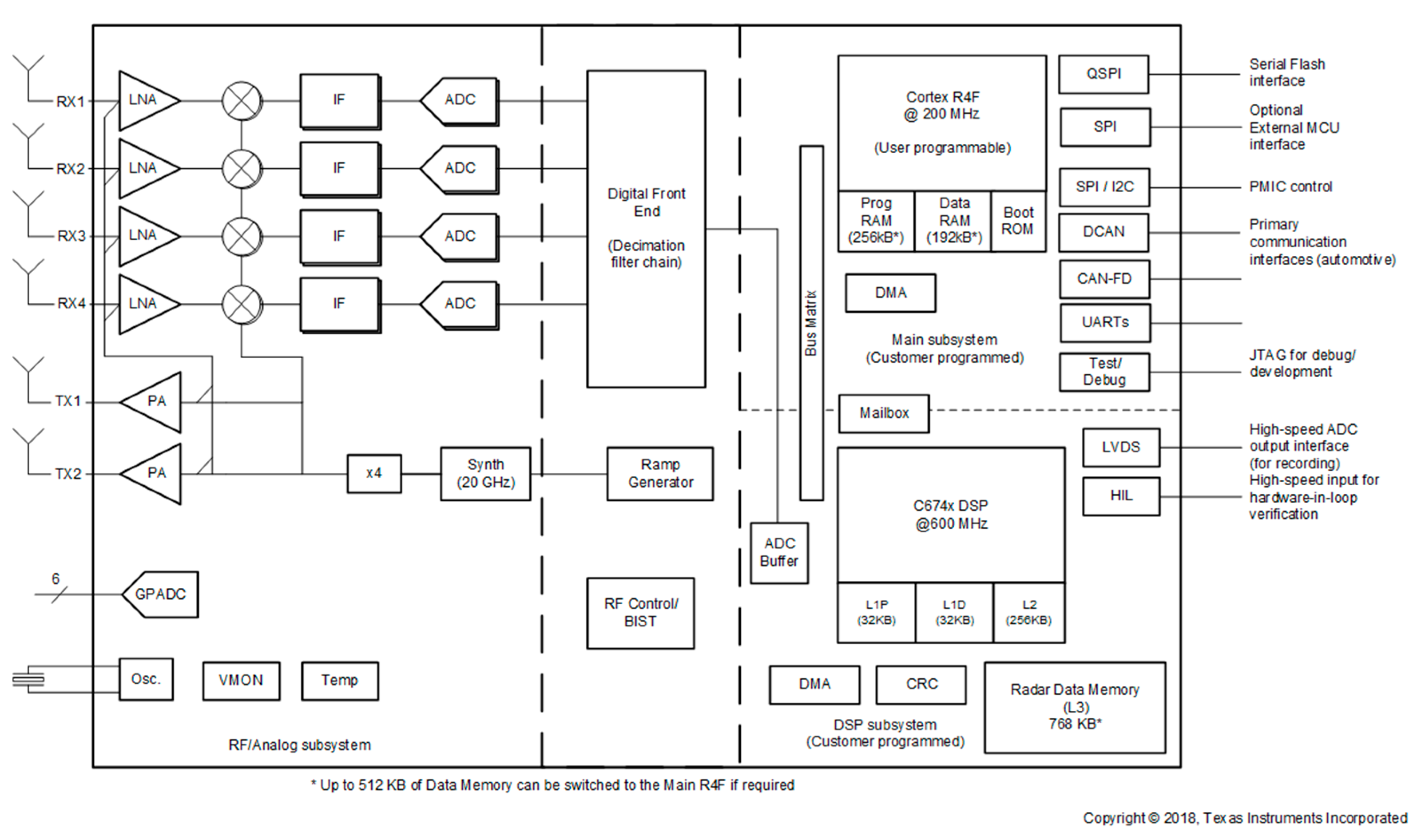
Figure 3.
Amplification and attenuation experimental setup for PA and LNA.
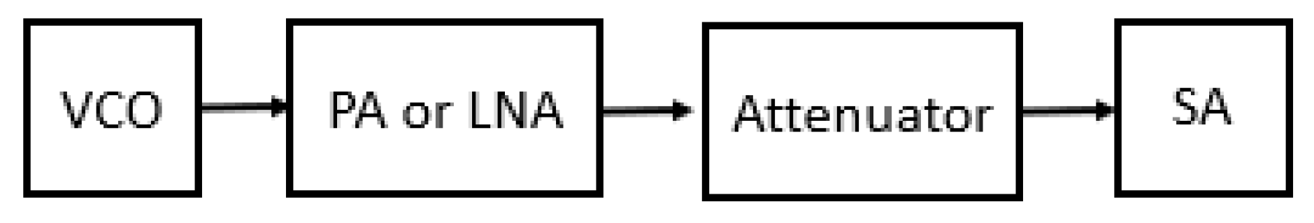
Figure 4.
Experimental setup for radio link.
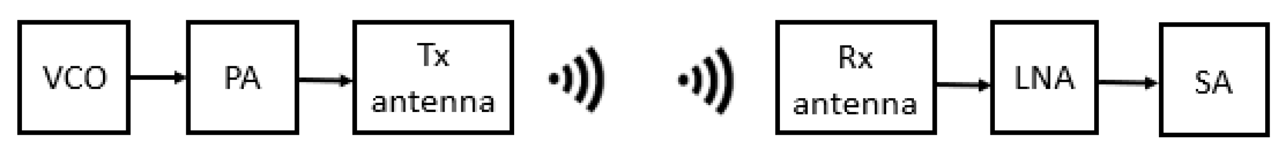
Figure 5.
Experimental setup for radio link with reflector.

Figure 6.
Flow chart of the educational method.
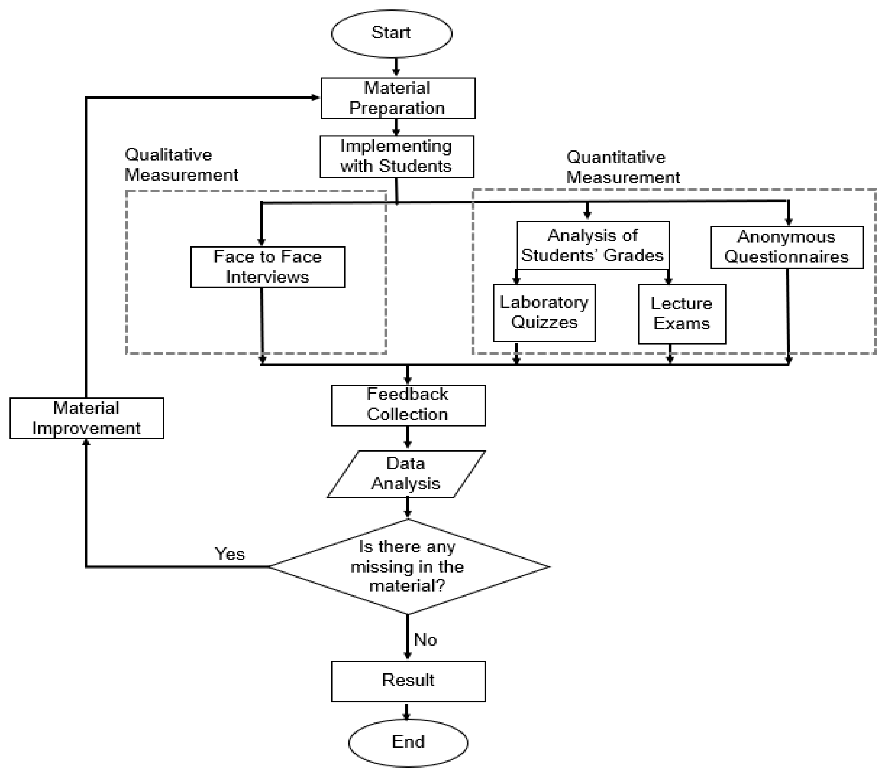

Table 1.
Survey-2.
| Item Asked | Avg. score | |
|---|---|---|
| About the course |
|
4,4 |
|
4,2 | |
|
4,5 | |
|
4,5 | |
|
4,7 | |
|
4,7 | |
|
4,3 | |
|
4,5 | |
|
3,3 | |
|
4,7 |
|
| About the experiments |
|
4,5 |
|
4,3 | |
|
4,7 | |
|
4,5 | |
|
4,5 | |
|
4,3 | |
|
4,7 | |
|
3,5 | |
|
4,8 | |
|
4,5 | |
Table 2.
Survey-3.
| Item Asked | Avg. | |
|---|---|---|
| General Questions |
|
3,7 |
|
4,0 | |
|
3,4 | |
|
3,4 | |
|
4,3 | |
|
4,4 | |
|
3,6 | |
|
4,1 | |
Table 3.
Grades.
| Exams | 1st Term | 2nd Term | 3rd Term |
|---|---|---|---|
| Laboratory Average | 53,3 | 81,3 | 77,0 |
| Course Quiz Average | 56,5 | 55,7 | 74,2 |
| Midterm Average | 51,5 | 67,0 | 60,1 |
| Final Average | 46,7 | 40,7 | 67,7 |
| Grade Average | 52,7 | 58,6 | 71,4 |
Disclaimer/Publisher’s Note: The statements, opinions and data contained in all publications are solely those of the individual author(s) and contributor(s) and not of MDPI and/or the editor(s). MDPI and/or the editor(s) disclaim responsibility for any injury to people or property resulting from any ideas, methods, instructions or products referred to in the content. |
© 2024 by the authors. Licensee MDPI, Basel, Switzerland. This article is an open access article distributed under the terms and conditions of the Creative Commons Attribution (CC BY) license (http://creativecommons.org/licenses/by/4.0/).
Copyright: This open access article is published under a Creative Commons CC BY 4.0 license, which permit the free download, distribution, and reuse, provided that the author and preprint are cited in any reuse.


