Submitted:
29 August 2024
Posted:
02 September 2024
You are already at the latest version
Abstract
In ocean engineering, accurate and efficient numerical simulations are crucial. Leveraging axisymmetry vastly enhances the efficiency of a simulation, reducing a three-dimensional scenario to a two-dimensional simulation. Exploiting axisymmetry enables a significant reduction in computational demand while maintaining simulation fidelity. In this paper, axisymmetry is leveraged to perform a large ensemble of simulations, in order to evaluate and maximise the accuracy and efficiency of a Computational Fluid Dynamics (CFD) simulation. In particular, the free decay motion and wave radiation from a heaving semi-submerged sphere are simulated, using the Reynolds Averaged Navier Stokes (RANS) solver, interFOAM, in the opensource finite volume CFD software OpenFOAM. Validated against highly accurate experimental data, extensive parametric studies are conducted, previously limited by computational constraints, which facilitate the refinement of simulation setups. More than 50 iterations of the same heaving sphere simulation are performed, informing efficient trade-offs between computational cost and accuracy across various simulation parameters and mesh configurations. Ultimately, by employing axisymmetry, this research contributes to the development of more accurate and efficient numerical modeling in ocean engineering.
Keywords:
Axisymmetry
; Computational Fluid Dynamics
; Ocean Engineering
; Numerical Wave Tank
; Hydrodynamics
; Fluid-structure interaction
; Validation
; OpenFOAM
1. Introduction
Computational Fluid Dynamics (CFD) is integral in ocean engineering, serving as a versatile tool for high-fidelity modeling across a broad spectrum of scenarios. The intricacies of ocean engineering applications pose unique challenges to CFD, encompassing two-phase flows with evolving free surfaces, fluid-structure interactions with moving bodies and the need for extensive computational domains to mimic the vast oceanic environment. These challenges are further compounded by the requirement to ensure numerical convergence and physically accurate simulations within feasible computational times. This necessitates a meticulous balance between the computational expense and the resolution of the spatial and temporal discretisation, often requiring iterative adjustments across a multitude of simulation parameters. A strategic approach enabling a vast amount (relatively) of simulation iterations to be performed involves exploiting geometric and physical symmetries within the simulation domain to reduce computational demands. Using this approach to optimise a CFD simulation is the topic of the present paper, considering the scenario of the free decay heave motion of a semi-submerged sphere and the resulting wave field radiated from the heaving sphere.
1.1. CFD Numerical Wave Tanks
With the rise of available computational power, the use of Numerical Wave Tanks (NWTs) in ocean engineering has been accelerating since the turn of the century [1,2]. NWTs provide a cost-effective testbed for experimentation, analysis, and optimization within ocean engineering. The integration of CFD with NWTs facilitates advanced simulations that can capture complex fluid-structure interactions and non-linear wave dynamics with high fidelity. Examples of CFD-based NWTs can be seen in various applications, such as naval architecture [3], wave energy conversion [4] and offshore wind [5,6]. Compared to physical wave tanks (PWTs), CFD-based NWTs offer several advantages:
- NWTs allow testing at any scale (including full scale). Whereas, PWTs inherently suffer scaling effects, being scaled down versions of the real ocean environment.
- Easy, non-invasive measurements of all variables. PWTs require measurement equipment, which are prone to noise and measurement error, in addition to possibly interfering the dynamics of the system being measured. NWTs allow all variables to be measured everywhere at any time.
- Specialist equipment and construction of prototype devices are not required. Seabed topographies can easily and rapidly be installed and altered. Easy and automated variation of any parameter. Things requiring days/weeks to physically manufacture and install in the real world for PWTs, can be generated in seconds/minutes in NWTs.
- Availability and accessability. There are limited PWT facilities globally, whose availability is generally booked-out months in advance. NWTs are constrained only by the availability of computational resources, which are vastly more accessible than PWT accessibility. Multiple NWT experiments can run at the same time.
Ultimately, PWT and NWT testing should be combined to leverage both their strengths [10]. In practice, deploying NWTs involves a detailed setup process. However, once established, employing the NWT for subsequent simulations and parametric studies is highly cost-effective. For example, Schmitt et al. [11] highlight that variations of structural shapes or mass properties can be assessed with minimal additional work once a case has been set up. Similarly, Kim et al. [12] emphasize the cost-effectiveness of NWTs for all subsequent simulations once the initial setup is complete.
The accuracy of an NWT, as well as the scope of oceanic scenarios to which it can feasibly be applied, is dependent on the computational resources available. Early NWTs were necessarily based on simplified versions of the complete mathematical description of fluid dynamics. The Navier-Stokes equations and their boundary conditions were simplified to more computationally feasible methods, such as potential flow theory, which required a trade-off between computational expense and fidelity [13]. However, modern NWTs can be implemented in CFD software, using Reynolds Averaged Navier Stokes (RANS) equations and fully dynamic nonlinear boundary conditions, providing a more rigorous treatment of the Navier-Stokes equations at great computational expense [14].
1.2. Exploiting Axisymmetry for Accelerated Simulations
Leveraging symmetry to reduce computational demands offers a strategic advantage in CFD for ocean engineering applications. This approach is exemplified in the calibration process for wave generation and absorption mechanisms [9,15,16,17], where employing a single cell in the dimension perpendicular to wave travel—coupled with symmetry planes— provides initial two-dimensional tank configurations to iteratively converge and calibrate the generation of the required environmental inputs, whilst minimising the computational domain and run times. Upon achieving desired wave generation and absorption outcomes, the simulation domain is expanded horizontally, into three dimensions, for the considered application and experiment.
Upon moving to three dimensions, longitudinal symmetry is often exploited, whereby a symmetry plane bisects the computational domain, proving effective for scenarios that exclude multidirectional waves and limit the motion of structures to heave, surge, and pitch. Examples include waves interacting with cylinders [18], wave energy converters (WECs) [19] and offshore wind turbines [20]. To optimize computational resources, high-dimensional calculations should be confined to areas of asymmetry, typically induced by structural elements. This methodology is detailed in [21,22], where a two-dimensional wave propagation zone is coupled with a three-dimensional structural analysis area.
Axisymmetric structures, operating in heave, are the only scenario including a structure that can be reduced to a two- dimensional simulation. Comprising a one-cell thick wedge shaped domain, whose central-axis aligns with the vertical-axis of the axisymmetric structure, these simulations achieve the same level of detail as their more computationally intensive three-dimensional counterparts, while necessitating only a fraction of the computational cells. This is demonstrated in [23] where the performance of several different numerical models are compared against experimental results for the free decay motion of a heaving sphere. One of the models (labeled RANS5 in [23]), exploits axisymmetry and yielded results that closely aligned with or surpassed the accuracy of four other RANS-based simulations, but with a computational speedup by a factor of 1000. This axisymmetry-centric approach even achieved a 2-5 times faster computation than the nonlinear potential flow models in [23].
Following the RANS5 model in [23], the present paper develops an axisymmetric numerical wave tank (A-NWT) for the heaving sphere. The computational efficiency of the A-NWT enables parameter sweeps to be conducted for the optimisation of the A-NWT performance.
1.3. Significance of High-Accuracy Validation Data
Validating CFD simulations requires precise and relevant experimental data. Discrepancies between simulation results and experimental observations are attributed to inaccuracies of the simulation. The use of high-accuracy validation data is therefore critical in ensuring that any deviations observed are genuinely indicative of the simulation model’s performance rather than artifacts of flawed or imprecise experimental benchmarks.
A cornerstone of the present case study is the highly accurate validation dataset from free decay experiments of a heaving sphere, detailed in [23]. This dataset, created with meticulous effort for high-fidelity simulations, is increasingly used as a benchmark. [24] compared methods to estimate numerical uncertainties with it. [25] used it for verifying and validating the MoodyMarine simulation tool. [26,27,28] employed it to train and validate machine learning models. [29] validated an overset algorithm for multiphase flows, and [30] evaluated two different CFD solvers with it. Unique to the present paper is the inclusion of wave radiation, in addition to the heave motion of the sphere. Previous studies, including [23] and subsequent works [24,25,26,27,28,29,30], only considered the sphere motion without wave radiation. For comparison, a different experimental dataset and numerical model validation study of free decay motion and wave radiation from a heaving sphere is recently presented in [31].
1.4. Outline of Paper
The present paper demonstrates how exploiting the symmetry of a floating axisymmetric structure enables extremely efficient CFD simulations, which then allows far greater investigation and optimisation of the various parameters in the CFD setup. The case study, considering the free-decay motion and wave radiation from a heaving sphere is presented in Section 2, detailing both the physical experiments and the A-NWT. Section 3 and Section 4 then present and discuss the results, detailing the comparison of the simulations against the experiments for varying parameters and solver settings as the performance of the A-NWT is optimised and then validated against different initial free decay amplitudes. Conclusions are then drawn in Section 5.
2. Heaving Sphere Study
The heaving sphere study in [23] presents dedicated validation experiments of the heave free decay of a semi-submerged sphere, representing a generic shape of single point-absorber WEC in lab scale, and subsequent comparison to various NWTs of different fidelity. An introduction to validation experiments and in specific those of [23] are given in [32]. The heaving sphere experiments in [23] are the first in a series of validation experiments with the sphere to be published by the OES Wave Energy Converters Modelling Verification and Validation working group [33]. Additional validation datasets are planned to be published revolving around wave excitation, wave radiation and power production with the wave excitation tests currently being processed, see [34].
The heave decay test case of [23] is summarized in Section 2.1. Descriptions are provided for both the physical experiments (Section 2.2) and the A-NWT (Section 2.3).
2.1. Test Case
A sphere with half the density of ambient water is held stationary and then released from three different initial drop heights: 0.1D (30 mm), 0.3D (90 mm), and 0.5D (150 mm), where D represents the sphere diameter, see Figure 1. These varying heights enable the investigation of linear to highly nonlinear heave decay responses. The governing physical parameters of the test case (measured values from the experiments) are given in Table 1.
2.2. Description of Physical Experiments
The validation experiments in [23] were conducted at the Ocean and Coastal Engineering Laboratory at Aalborg University, Denmark. Four repetitions were carried out for each drop height to enable estimation of random uncertainty.
2.2.1. Properties of the Sphere and the PWT
2.2.2. Measurement Equipment
The position of the sphere was tracked using a Qualisys optical motion capture system, which employed four Oqus7+ cameras operating at 300 fps. Reflective markers were placed on the sphere to ensure precise motion tracking (visible in Figure 2). The system’s calibration and setup provided a high measurement accuracy, with systematic standard uncertainties kept below 0.01 mm.
To initiate the tests, a mechanical release system comprising a pushrod and an electrical actuator was used. This system ensured consistent and precise release timings, measured by high-speed cameras at 960 fps. The release mechanism’s design minimized initial disturbances to the sphere, providing clean initial conditions for the decay tests [32]. Three wave gauges were strategically placed within the tank to measure the radiated waves generated by the heave motion of the sphere.
2.2.3. Heave Motion Results
As shown in [23], the exact position of the initial release height varied slightly between the repeated tests. In the following, the displacements are normalised against the actual measured initial drop height, as plotted in Figure 4. Additionally, following [23], the time scale is normalised against the natural heave period of the sphere, s.
2.2.4. Wave Radiation Results
The free surface elevation, normalised against the measured drop height, measured at each wave gauge is plotted in Figure 5 for the three initial drop heights. The repeatability of the measured free surface elevations, between the four repetitions, is strongly evident. The variability between repetitions appears largest for the smallest amplitude initial drop height, when the results are normalised, as any absolute experimental error is a larger relative error for an experiment involving smaller amplitudes.
2.3. Description of the Axisymmetric Numerical Wave Tank
This section details the implementation of the A-NWT used in the present study. The A-NWT is designed to simulate the heave motion and wave radiation of a semi-submerged sphere, leveraging the efficiency gains from axisymmetry. Differences between this setup and the previously established RANS5 model from [23] are also discussed.
2.3.1. Implementation
The A-NWT was implemented using the OpenFOAM software [35], which is widely adopted in ocean engineering for simulating wave-structure interactions [36]. OpenFOAM offers a flexible platform for setting up NWTs through its various solvers and meshing tools. The general implementation of an OpenFOAM-based NWT is described in [37].
In this study, the A-NWT is configured using a wedge-shaped computational domain, as shown in Figure 6. This wedge shape allows the simulation of axisymmetric flow around the heaving sphere while reducing the three-dimensional problem to a two-dimensional one, significantly lowering computational costs. The front and back faces of the wedge are assigned the wedge boundary condition, essential for maintaining axisymmetry in the simulation. The list of boundary conditions used in the A-NWT setup is provided in Table 2. The Volume of Fluid (VOF) based interFoam solver, part of the OpenFOAM suite, is utilized for solving the two-phase flow and capturing the interface between water and air. The sphere motion is calculated using the rigidBodyMotion solver and the resulting dynamic mesh motion is handled using the mesh morphing approach (see [38]).
The optimization of the A-NWT’s performance, including the selection of appropriate parameters and boundary conditions, is discussed in more detail in Section 3.
2.3.2. Differences to the RANS5 model
The A-NWT implemented in this study differs from the RANS5 model described in [23] in several key aspects:
- Objective: The primary objective of the present A-NWT is to accurately capture both the heave motion of the sphere and the radiated wave field. In contrast, the RANS5 model focused solely on the sphere’s heave motion. This difference necessitates a more refined meshing strategy, especially around the free surface, and adjustments to various solver parameters to accommodate the additional complexity of wave radiation.
- OpenFoam version: The RANS5 model was implemented using the OpenFOAM v7 (Foundation) version of OpenFOAM, whereas the present study uses the OpenFOAM v2312 (ESI) version.
- Sphere Motion Solver: The RANS5 model employs OpenFOAM’s sixDoFRigidBodyMotion solver, whereas the present study uses OpenFOAM’s rigidBodyMotion solver.
-
Water Depth and Tank Configuration: In the RANS5 model, the water depth was set to 6D to mitigate issues related to mesh deformation and the stability of the heaving sphere simulations. The deeper tank was chosen to avoid mesh compression problems beneath the sphere during large vertical displacements, which could lead to simulation crashes due to poor mesh quality.However, this increased depth was a compromise that potentially neglected the hydrodynamic effects of the tank floor on the sphere’s motion and the radiated wave field. In the current study, the A-NWT has been configured to use a water depth of 3D, matching the physical experiments. Extensive debugging and optimization were performed to stabilize the simulations with this more realistic tank depth, ensuring that the tank floor’s influence on wave radiation is accurately captured.
- Mesh Generation: The RANS5 model used a combination of OpenFOAM mesh generation tools of blockMesh and snappyHexMesh. However, this approach encountered issues in the present study when using the wedge boundary condition. Specifically, the mesh points generated around the sphere did not lie perfectly in a plane, causing conflicts with the axisymmetry requirements of the wedge boundary condition. To address this, the mesh generation was switched to cfMesh, which could ensure that the front face of the mesh maintained perfect alignment with the axisymmetric plane - a critical requirement for the wedge boundary condition and overall simulation accuracy.
3. Results
This section presents the simulation results from various parameter sweeps, followed by a discussion to identify optimal parameter ranges for enhancing the A-NWT’s performance in terms of both accuracy and computational efficiency. The analysis begins with the sphere motion results for the test case in Section 3.1, followed by an examination of wave radiation in Section 3.2. The case serves as the basis for model optimization, with the final results shown in Section 3.3, and this model is then compared against the 0.1D and 0.5D cases in Section 3.4.
3.1. Sphere Motion
This subsection details the spatial and temporal discretisation convergence studies performed to minimize the number of cells in the A-NWT while maximizing the time-step size. The impact of various solver settings on the accuracy and runtime of the simulations is also examined to improve the A-NWT’s overall performance.
3.1.1. Temporal and Spatial Discretisation
The goal of this study is to determine the optimal level of temporal and spatial discretisation, which ensures accurate results with minimal computational effort.
- Time Step
Two methodologies were evaluated for temporal discretisation:
- Adaptive Time Step Method: Based on a maximum Courant number, C, criterion with refinement levels of .
- Fixed Time Step Method: Using fixed time steps of .
- Mesh Setup
The mesh setup is depicted in Figure 7. The tank wall is positioned 4.22 m from the sphere axis, the tank floor is set below the sphere center, and the atmosphere boundary is placed above the sphere’s center. The front and back faces have aspect ratios close to one, i.e., square, and extruded around the central axis to form the wedge. The background mesh has a maximum cell size of D/4, with refinement levels bisecting in both directions of the x-z plane. The refinement region around the sphere center extends 3D horizontally and vertically below the sphere, and only 4/3D above the sphere center, as the influence of air is negligible [17]. The majority of cells are hexahedral and polyhedral cells are employed to connect different refinement levels.
- Mesh Resolutions
Four levels of mesh refinement around the sphere and free surface are examined, , as depicted in Figure 8.
- Results of Parametric Study
Figure 9 compares the A-NWT results from the coarsest and finest discretisations (both spatial and temporal), for the adaptive and fixed time step methods, against the experimental data. As expected, with increased discretisation resolution, the A-NWT results converge and deviations to the experimental data are significantly reduced.
Figure 10 and Figure 11 display the results for the adaptive and fixed time step methods, respectively. The A-NWT results are compared against the PWT data, focusing on the first peak (subplots a-d) and the second trough (subplots e-h) of the sphere motion. Each plot compares the five levels of temporal discretisation and the four levels of mesh refinement are compared across different subplots. The following observations can be made:
- Temporal Discretisation: The amplitude of the A-NWT results decrease with finer temporal discretisation, converging to a solution for time steps of approximately and .
- Spatial Discretisation: The A-NWT results are seen to converge as the mesh cell size is decreased, however the convergence appears oscillatory. The oscillatory convergence is further illustrated in Figure 12, where results for all spatial discretisations (including an additional refinement level of ) are plotted for the same temporal discretisation (). The amplitude of the first peak for the mesh is within 0.15% of the amplitude for the mesh. For the second trough however, the difference is significantly larger, with the amplitude being 5.1% larger for the mesh compared to the mesh.
- Accuracy: The results appear to converge very closely to the experimental results. Both the amplitude and phase of the first peak and second trough appear to converge within 1% of the experimental results. Refinements to the solver settings, later in this Section, will look to further improve this accuracy.
Figure 13 examines the size of the time steps and the corresponding Courant numbers for the different temporal discretisation methods. For the fixed time step method, the coarsest discretisation of (subplot a), results in large Courant number with for almost the entire simulation except for a short period after the initialization where the velocities in the A-NWT are zero as initial conditions. For the finest discretisation of (subplot b), the Courant number remains between: for the majority of the simulation. Considering the adaptive time step method, the coarsest discretisation of results in times between: for the majority of the simulation. For the finer discretisation of , the resulting time step mainly sits between , exceeding the finest discretisation level used for the fixed time steps. However, it should be noted that for the initial time steps, when the velocities in the A-NWT are low, the size of the time steps exceed .
Considering the effect of the large time steps taken by the adaptive time step methods during the first few time steps of the simulation, a possible solution is to also include a maximum allowable time step in the simulation settings. Figure 14 compares the results of the adaptive time step method, considering a discretisation of [, with and without a maximum allowable time step imposed. Without the maximum allowable time step, Figure 14(a) shows that the first initial steps appear quantised and large compared to the more smooth continuous trace that results when employing the maximum allowable time step. The result of this mismatch at the start is propagated to the trajectories at the 1st peak, Figure 14(b), and 2nd trough, Figure 14(c), where the max/min amplitudes are slightly larger and earlier for the simulations employing the maximum allowable timestep in addition to the Courant number, however the differences are very small.
- Selected Discretisation
For the next round of iterative evaluation and refinement of the model, the spatial discretisation is selected as . For the temporal discretisation, the adaptive time stepping approach is selected with and the additional constraint of a maximum allowable time step of .
3.1.2. Mesh Refinement Area
Next, we seek to reduce the amount of cells by reducing the area of the refinement region. The initial mesh had a refinement region extending 3D both horizonatally and vertically, Figure 15(a). Here, we reduce this distance, in increments of 0.5D, down to D in order to identify the smallest length for which the results still agree with the initial refinement area of length 3D. Figure 15(b) depicts the mesh refinement for the case with a refinement length of 2D and Figure 15(c) shows the 1D case.
The results are then presented in Figure 16, again showing the evolution of the sphere heave displacement at the first peak, Figure 16(a), and the second trough, Figure 16(b). A comparison of the relative accuracy and the cell count compared to the 3D case, is plotted in Figure 16(c). Refinement areas of are seen to return the amplitude value of the first peak and second trough to within 99.5% of the original refinement area. Halving the size of the refinment area from to reduces the cell count to nearly a third (36.7%). Decreasing the mesh refinement area further to reduces the cell count to nearly one quarter (25.7%), however the decrease in relative accuracy is seen to increase significantly compared to the larger refinements areas. Moving from the refinement area to the area, the relative accuracy drops from 0.9977% and 0.9975%, for the peak and trough amplitudes respectively, to 0.9928% and 0.9884%. For the subsequent iterations of evaluation and refinement of the model set up, a mesh refinement area of is employed, favouring towards maintaining a high accuracy over reduction in computational speed.
3.1.3. Wedge Angle
The spatial discretisation used in the angular direction may play a role in the accuracy of the results. Particularly for the method in which the present A-NWT is meshed, where the mesh edges in the angular directions are straight lines, rather than circularly curved, as depicted in Figure 17. To examine the effect of the wedge angle on the results, simulations are performed for six different wedge angles, .
The heave motion response for the various wedge angles are plotted in Figure 18. The results are seen to converge with decreasing wedge angle. Greater discrepancies can be observed for the troughs (subplot b) compared to the peaks (subplot a), though a similar trend with a greater than linear increase in divergence with increasing wedge angle, as seen in subplot (c). For the second trough, the relative difference compared to the smallest wedge angle exceeds 1% when the wedge angle exceeds about 6°.
For the A-NWT, the size of the wedge angle does not influence the cell count and has little relevance to the computational expense of the simulation. Therefore, we are free to choose small wedge angles, with converged results. However, when moving to three-dimensional simulations, the size of the wedge angle gives an indication of the resolution required for the discretisation in the horizontal plane, discussed further in Section 4.1.
For the subsequent iterations for the evaluation and refinement of the model set up, a wedge angle of 2° is employed.
3.1.4. Solver Settings
The effect of several solver settings on the performance of the A-NWT are investigated:
- Acceleration Relaxation
The accelerationRelaxation parameter in the rigidBodyMotion solver helps stabilize simulations involving rigid body dynamics by smoothing out rapid changes in acceleration. This prevents numerical instabilities, such as oscillations or divergence, especially in cases with rapidly changing forces. While lowering this parameter increases stability, it may also slow down the body’s response to forces, potentially reducing accuracy. Therefore, it’s essential to find a balance that ensures both stability and accurate motion representation. The value of accelerationRelaxation typically ranges between 0 and 1. A value of 1 means no relaxation is applied (i.e., the full computed acceleration is used), while a value closer to 0 means more relaxation is applied (i.e., the acceleration is smoothed more aggressively). The initial simulations employed an accelerationRelaxation of 0.7, which is compared in Figure 19 against results using accelerationRelaxation values of 0.8 and 0.9. Increasing the accelerationRelaxation is seen to not have a significant effect on the sphere motion, only very slightly decreasing the amplitude.
- PIMPLE Iterations
The PIMPLE algorithm combines the PISO (Pressure-Implicit with Splitting of Operators) and SIMPLE (Semi-Implicit Method for Pressure-Linked Equations) methods to solve fluid flow equations, particularly in transient simulations. It iteratively corrects pressure and velocity fields within each time step, enhancing convergence and accuracy, especially in complex or large-time-step scenarios. While increasing PIMPLE iterations improves simulation accuracy by reducing numerical errors, it also increases computational time, requiring a balance between accuracy and efficiency. The initial simulations employed two PIMPLE iterations. Figure 20 compares the results using up five PIMPLE iterations, with dramatic improvement between 1 and 2 PIMPLE iterations, then another significant improvement between 2 and 3 PIMPLE iterations, after which the results start to converge.
- PIMPLE Iterations + Inner Loop Mesh Motion
This approach involves updating the mesh geometry within each PIMPLE iteration. By continuously adjusting the mesh, the solver maintains alignment with the object’s motion, ensuring precise representation of wave patterns and force distributions. Although this process increases computational overhead, it enhances simulation fidelity and prevents inaccuracies that could arise from mesh distortion or misalignment. The initial simulations did not update the mesh motion within each PIMPLE iteration. Figure 21 shows the results when the inner loop mesh motion is applied. Here both the amplitude and the period of the sphere motion is seen to decrease with increasing number of PIMPLE iterations. Compared to the results in Figure 20, it can be seen that employing inner loop mesh motion results in the sphere motion being closer to the experimental results.
- Turbulence Modelling
Turbulence modelling uses mathematical models like the SST [39] to simulate turbulent effects without resolving small-scale motions directly, which would require very fine meshes and significant computational power. These models aim at enhancing simulation accuracy, particularly near walls and in wake regions, but at the cost of decreased computational efficiency. Initial simulations assumed laminar flow, with no turbulence models applied. Figure 22 shows the impact of adding the SST model, using both default1 tutorials and doubled parameter values. Including this turbulence model reduced the amplitude of the sphere motion closer to the experiments, with the trace at the first peak falling within the spread of the four experimental repetitions (Test 1-4). The amplitude of the trough still overshoots the experimental results, however the inclusion of the turbulence model reduces this overshoot from 3.3% to 2.7%. Doubling the turbulence parameters slightly lowered the amplitude further, indicating some sensitivity to these values.
3.2. Radiated Wave
The motion of the sphere generates a wave that is radiated axisymmetrically until interacting with the tank walls (where the rectangular tank walls break the axisymmetry). Figure 23 depicts the radiated wave through several snapshots of the alpha.water and p_rgh fields on the front face of the A-NWT. Pictured in the snapshots on the left, alpha.water=1 corresponds to cells of pure water, alpha.water=0 corresponds to pure air and alpha.water values in between lay in the vicinity of the free surface interface. The free decay motion of the sphere is seen to vary the height of the free surface, a disturbance which propagates outwards towards the wall as time increases. In the snapshots on the right, the dynamic pressure, p_rgh, is the value of the total pressure minus the hydrostatic pressure. Visualising the dynamic pressure gives a clearer view of the radiated wave with increasing and decreasing pressure fields in the water. The position of the wave gauges, WG1-3, are also visible in these snapshots, whose measured time traces can be seen in Figure 24.
Figure 24 compares the normalized free surface elevations recorded in the A-NWT simulations against experimental results across the three wave gauges. An additional simulation with an expanded mesh refinement area, as shown in Figure 25, is included. Subplot (a) of Figure 25 shows the original mesh at , where the mesh refinement around the still water level doesn’t fully accommodate the sphere’s motion, leading to a coarser capture of the free surface. Subplot (b) highlights this issue when the sphere reaches its first trough. The updated mesh in subplots (c) and (d) addresses this by expanding the refinement area, ensuring the free surface remains within the finest mesh throughout the oscillation.
The results in Figure 24(a)-(c) demonstrate that the A-NWT closely replicates the experimentally observed wave radiation. The overall wave trace matches well, though accuracy diminishes toward the end (possibly due to non-axisymmetric wall reflections in the experiments). Additionally, a closer inspection reveals the A-NWT misses some higher-order harmonics present in the experiments (see Figure 24(d) and (e))) and slightly overpredicts the height of the initial wave peaks (see Figure 24(f)). The larger mesh refinement area is seen to slightly improve the results.
3.3. The A-NWT Results
The optimized A-NWT produced results that demonstrate a high degree of accuracy in capturing the dynamics of the heaving sphere and the associated wave radiation. Figure 26 shows the results for the optimised A-NWT. The parameters selected for the final A-NWT configuration are summarized in Table 3. These parameters were refined and optimised based on the resulting A-NWT performance, considering the trade-off between computational expense and the accuracy compared to the experiments. The heave free decay motion, Figure 26(a) is captured very well, exemplified by the the zoomed in plot of the first peak, Figure 26(b), where the A-NWT results fall within the range of the experimental repetitions, highlighting the model’s accuracy. However, it is noted that the A-NWT slightly overshoots the amplitude of the troughs, as shown in the zoom in plot in Figure 26(c).
The A-NWT also accurately replicated the wave radiation patterns observed in the PWT experiments. The comparison between the simulated and experimental wave elevations at the wave gauges (WG3-1), Figure 26(d)-(f), indicates that the A-NWT successfully captures the primary wave characteristics, including the timing and amplitude of the wave peaks. However, as discussed in Section 3.2, there is a slight overestimation of the initial wave peaks, some slight deviations towards the end of the signal and a harmonic component in the PWT signals not well captured in the A-NWT.
3.4. Validation Against Other Drop Heights
Here, the A-NWT setup described in Section 3.3, which is optimised for the initial drop height, is validated against the and initial drop heights, depicted in Figure 27 and Figure 28, respectively. Overall, the A-NWT simulations are seen to very closely replicate the experimental results. For the heave free decay motion (subplot a), the A-NWT results appear mostly indistinguishable from the PWT results. However, the zoom in of the first peak and second trough (subplots b and c) show a slight discrepency for the drop heights, whereas for the drop height the A-NWT results are inbetween the results from the four repetitions in the PWT (Test 1-4), highlighting excellent accuracy.
For the radiated wave, the A-NWT results closely match the measured free surface elevations in the experiments. Similar to the results for the initial drop height, there is a slight overestimation of the initial wave peaks, some slight deviations towards the end of the signal and a harmonic component in the PWT signals not well captured in the A-NWT. These observations suggest that while the A-NWT is highly accurate overall, further refinement could be pursued to improve the capture of fine wave details.
4. Discussion
The performance of the A-NWT was rigorously evaluated, and the results demonstrate both high accuracy and efficiency. This discussion addresses the strengths and limitations of the A-NWT, with a focus on its accuracy, computational expense, and considerations for future studies.
4.1. The A-NWT performance
The A-NWT performed very well, in terms of both accuracy and computational expense:
-
Accuracy : The A-NWT results demonstrated excellent accuracy across multiple initial drop heights. For the heave motion, the alignment between A-NWT results and experimental data improved with increasing initial drop height. The A-NWT results for the largest drop height () fell within the range of the four repeated tests in the PWT, showcasing exceptional accuracy. For the middle drop height (), the peaks matched the experimental results well, though the troughs were slightly overpredicted. The smallest drop height () exhibited minor discrepancies for both peaks and troughs.Regarding wave radiation, the A-NWT successfully captured the dominant trend of the free surface elevation at the three different wave gauge locations. However, a second harmonic component, evident in the experimental results, was not as pronounced in the A-NWT simulations. Additionally, discrepancies increased towards the end of the signals, likely due to the breakdown of axisymmetry in the PWT as the earliest radiated waves reflected off the tank walls and returned to the wave gauges.
- Computational Expense : The A-NWT’s computational efficiency is a significant advantage. The final A-NWT mesh comprised approximately 150,000 cells, and simulation runtimes were manageable even on modest computational resources. Running the A-NWT simulations on 24 cores required 10.7 [h], on 12 cores 16.7 [h] and on 6 cores 25.8 [h]. To estimate the computational expense when moving to a three-dimensional simulation, the plot in Figure 18(c) offers some insight where the results appear to begin diverging between 2 - 4°2. Angularly discretising 360° by such sized wedges requires between 90 - 180 cells in the third dimension, thus the total cell count for the three dimensional NWT could be around 15M. To run a simulation within a day, would require a HPC with more than 600 cores3.
4.2. Initial Time Steps
While adaptive time-stepping offers a generally efficient approach, it can lead to excessively large initial time steps due to the low velocities at the start of the simulation. These large time steps, although not critical for the fluid domain’s solution, can adversely affect the accuracy of the rigid body motion solver, particularly in predicting the initial trajectory of the sphere. This issue is significant, as seen in some initial CFD simulations compared in the original study [23], where large initial time steps caused substantial deviations from experimental results. These simulations required subsequent adjustments to become useful, highlighting the importance of carefully managing time steps at the simulation’s outset.
To address this, the present study found that implementing a dual criterion—enforcing both a maximum allowable time step (e.g., ) alongside the maximum Courant number condition—strikes an effective balance. This approach ensures that the solver selects the smaller of the two time step options, thereby maintaining the accuracy of the simulation from the very beginning.
4.3. Future Studies
In addition to moving to three dimensions, the results from this study open several avenues for future research:
- Mesh Optimisation – Further studies can work to reduce the required number of mesh cells whilst retaining the accuracy of the results. Increasing the aspect ratio of cells in certain regions, to increase/decrease the spatial discretisation resolution more in one direction without also increasing in the other direction, might be of interest.
- Time-Step Refinement – While the chosen time step of was found to be effective, it was selected based on a trial with a discretization level of 2. Future work could explore intermediate values between and , potentially identifying an optimal balance that allows for even larger time steps without compromising accuracy.
- Overset Mesh - Compare performance of the current mesh morphing with the overset method. While the mesh morphing is seen to work well in heave, for other degrees of freedom, in particular pitch, roll and yaw, the mesh morphing gets twisted and simulations crash [38]. For these cases, the overset approach is necessary within OpenFOAM, therefore it would be of interest to understand how well it performs, in terms of accuracy and simulation time, compared to the mesh morphing method.
- Wave Radiation - Further investigation to improve the simulation of the wave radiation, in order to replicate the smaller initial peak values and and the emergence of a second harmonic observed in experimental data. Future studies could benefit from analyzing wave radiation in the frequency domain, allowing for a more detailed comparison and understanding of these phenomena.
5. Conclusion
This study demonstrates the significant advantages of leveraging axisymmetry in Computational Fluid Dynamics (CFD) simulations for modeling the free decay motion and wave radiation from a heaving semi-submerged sphere. By reducing a three-dimensional problem to a two-dimensional axisymmetric framework, the research achieved substantial computational efficiency without sacrificing accuracy. This efficiency enabled an extensive series of parametric studies, previously constrained by computational limitations, culminating in over 50 iterative simulations. These iterations refined the CFD setup, offering valuable insights into balancing computational cost and accuracy. pecifically, optimal performance was obtained with a spatial discretization using cells of length equal to one 128th of the sphere’s diameter, within an area extending 1.5 times the sphere’s diameter from its center, and a temporal discretization employing an adaptive time step with a maximum Courant number of 1/8.
The Axisymmetric Numerical Wave Tank (A-NWT) developed in this study was rigorously validated against high-fidelity experimental data across various initial conditions, demonstrating impressive accuracy. The A-NWT effectively captured the heave decay motion and wave radiation observed in physical experiments, with minor discrepancies primarily in the finer details of the wave field. These included a slight overestimation of wave peaks and challenges in accurately capturing higher-order harmonics, which were consistent across different drop heights and suggest areas for future refinement.
The research highlights the importance of optimizing temporal and spatial discretization, mesh refinement, and solver settings, to achieve an optimal balance between computational efficiency and simulation fidelity. Looking forward, future studies should aim to extend this work to three-dimensional simulations, further optimize mesh and solver configurations, and enhance the accuracy of wave radiation modeling. These efforts will contribute to the development of even more robust and efficient CFD tools for ocean engineering applications.
Author Contributions
Conceptualization, J.D.; methodology, J.D.; software, J.D.; validation, J.D., M.K. and J.A.; formal analysis, J.D., M.K. and J.A.; investigation, J.D., M.K. and J.A.; resources, M.K.; data curation, J.D., M.K. and J.A.; writing—original draft preparation, J.D., M.K. and J.A.; writing—review and editing, V.N.; visualization, J.D., M.K. and J.A.; supervision, V.N. and M.K.; project administration, V.N. and M.K.; funding acquisition, V.N. All authors have read and agreed to the published version of the manuscript.
Funding
Josh Davidson is funded by MCIN and by the European Union NextGenerationEU/PRTR-C17.I1, as well as by IKUR Strategy under the collaboration agreement between Ikerbasque Foundation and BCAM on behalf of the Department of Education of the Basque Government. Vincenzo Nava is funded by the Spanish Ministry of Economic Affairs and Digital Transformation in the framework of IA4TES project ( with reference number MIA.2021.M04.008, as well as the Spanish Ministry of Science and Innovation projects with references TED2021-132783B-I00 and PID2019-108111RB-I00 (FEDER/AEI). The study has also carried out within the “BCAM Severo Ochoa” accreditation of excellence CEX2021-001142-S / MICIN / AEI / 10.13039/501100011033; and the Basque Government through the BERC 2022-2025 program. Jacob Andersen and Morten Bech Kramer are funded by the Danish Energy Technology Development and Demonstration Program (EUDP) under project number 134232-510153.
Data Availability Statement
The benchmark dataset of the physical heave decay tests is publicly available from the supplementary material of the paper https://www.mdpi.com/1996-1073/14/2/269/s1 and at the OES webpage
Conflicts of Interest
The authors declare no conflicts of interest.
Abbreviations
The following abbreviations are used in this manuscript:
| A-NWT | Axisymmetric Numerical Wave Tank |
| CFD | Computational Fluid Dynamics |
| D | Diameter of Sphere |
| NWT | Numerical Wave Tank |
| PWT | Physical Wave Tank |
| RANS | Reynolds Averaged Navier Stokes |
| WEC | Wave Energy Converter |
| 1 | Default refers to the parameter values used in the interFoam tutorial cases: DTCHull, DTCHullMoving and motorBike, included in the OpenFOAM version 2306 release, that employ the SST model. |
| 2 | It should be noted that the mesh cells comprise straight lines only. Capturing the curvature of the radial faces with a spline instead may alter this result. |
| 3 | Running the simulation on 6 cores took approximately 24 hours, with 25k cells peer core. Therefore, parallelising the 15M cells to 25k cells per core would require 600 cores |
References
- Ortloff, C.; Krafft, M. Numerical Test Tank: Simulation of Ocean Engineering Problems by Computational Fluid Dynamics. Offshore Technology Conference. OTC, 1997, pp. OTC–8269.
- Kim, C.; Clement, A.; Tanizawa, K. Recent research and development of numerical wave tanks-a review. International Journal of Offshore and Polar Engineering 1999, 9. [Google Scholar]
- Stern, F.; Wang, Z.; Yang, J.; Sadat-Hosseini, H.; Mousaviraad, M.; Bhushan, S.; Diez, M.; Sung-Hwan, Y.; Wu, P.C.; Yeon, S.M.; others. Recent progress in CFD for naval architecture and ocean engineering. Journal of Hydrodynamics 2015, 27, 1–23. [Google Scholar]
- Windt, C.; Davidson, J.; Ringwood, J.V. High-fidelity numerical modelling of ocean wave energy systems: A review of computational fluid dynamics-based numerical wave tanks. Renewable and Sustainable Energy Reviews 2018, 93, 610–630. [Google Scholar]
- Xu, S.; Xue, Y.; Zhao, W.; Wan, D. A review of high-fidelity computational fluid dynamics for floating offshore wind turbines. Journal of Marine Science and Engineering 2022, 10, 1357. [Google Scholar]
- Zhang, W.; Calderon-Sanchez, J.; Duque, D.; Souto-Iglesias, A. Computational Fluid Dynamics (CFD) applications in Floating Offshore Wind Turbine (FOWT) dynamics: A review. Applied Ocean Research 2024, 150, 104075. [Google Scholar]
- Draycott, S.; Davey, T.; Ingram, D.; Day, A.; Johanning, L. The SPAIR method: Isolating incident and reflected directional wave spectra in multidirectional wave basins. Coastal Engineering 2016, 114, 265–283. [Google Scholar] [CrossRef]
- Windt, C.; Untrau, A.; Davidson, J.; Ransley, E.J.; Greaves, D.M.; Ringwood, J.V. Assessing the validity of regular wave theory in a short physical wave flume using particle image velocimetry. Experimental Thermal and Fluid Science 2021, 121, 110276. [Google Scholar] [CrossRef]
- Windt, C.; Davidson, J.; Schmitt, P.; Ringwood, J.V. On the assessment of numerical wave makers in CFD simulations. Journal of Marine Science and Engineering 2019, 7, 47. [Google Scholar]
- van Essen, S.; Scharnke, J.; Bunnik, T.; Düz, B.; Bandringa, H.; Hallmann, R.; Helder, J. Linking experimental and numerical wave modelling. Journal of Marine Science and Engineering 2020, 8, 198. [Google Scholar] [CrossRef]
- Schmitt, P.; Doherty, K.; Clabby, D.; Whittaker, T. The opportunities and limitations of using CFD in the development of wave energy converters. Marine & Offshore Renewable Energy 2012, pp. 89–97.
- Kim, J.W.; Jang, H.; Baquet, A.; O’Sullivan, J.; Lee, S.; Kim, B.; Read, A.; Jasak, H. Technical and economic readiness review of CFD-based numerical wave basin for offshore floater design. Offshore Technology Conference. OTC, 2016, p. D011S014R002.
- Davidson, J.; Costello, R. Efficient nonlinear hydrodynamic models for wave energy converter design—A scoping study. Journal of Marine Science and Engineering 2020, 8, 35. [Google Scholar]
- Ferziger, J.H.; Perić, M.; Street, R.L. Computational methods for fluid dynamics; springer, 2019.
- Miquel, A.M.; Kamath, A.; Alagan Chella, M.; Archetti, R.; Bihs, H. Analysis of different methods for wave generation and absorption in a CFD-based numerical wave tank. Journal of Marine Science and Engineering 2018, 6, 73. [Google Scholar] [CrossRef]
- Machado, F.M.M.; Lopes, A.M.G.; Ferreira, A.D. Numerical simulation of regular waves: Optimization of a numerical wave tank. Ocean Engineering 2018, 170, 89–99. [Google Scholar] [CrossRef]
- Larsen, B.E.; Fuhrman, D.R.; Roenby, J. Performance of interFoam on the simulation of progressive waves. Coastal Engineering Journal 2019, 61, 380–400. [Google Scholar] [CrossRef]
- Li, Z.; Bouscasse, B.; Ducrozet, G.; Gentaz, L.; Le Touzé, D.; Ferrant, P. Spectral wave explicit navier-stokes equations for wave-structure interactions using two-phase computational fluid dynamics solvers. Ocean Engineering 2021, 221, 108513. [Google Scholar]
- Windt, C.; Davidson, J.; Ringwood, J.V. Numerical analysis of the hydrodynamic scaling effects for the Wavestar wave energy converter. Journal of Fluids and Structures 2021, 105, 103328. [Google Scholar] [CrossRef]
- Wang, Y.; Chen, H.C.; Koop, A.; Vaz, G. Verification and validation of CFD simulations for semi-submersible floating offshore wind turbine under pitch free-decay motion. Ocean Engineering 2021, 242, 109993. [Google Scholar] [CrossRef]
- Di Paolo, B.; Lara, J.L.; Barajas, G.; Losada, Í.J. Wave and structure interaction using multi-domain couplings for Navier-Stokes solvers in OpenFOAM®. Part I: Implementation and validation. Coastal Engineering 2021, 164, 103799. [Google Scholar]
- Di Paolo, B.; Lara, J.L.; Barajas, G.; Losada, I.J. Waves and structure interaction using multi-domain couplings for Navier-Stokes solvers in OpenFOAM®. Part II: Validation and application to complex cases. Coastal Engineering 2021, 164, 103818. [Google Scholar] [CrossRef]
- Kramer, M.B.; Andersen, J.; Thomas, S.; Bendixen, F.B.; Bingham, H.; Read, R.; Holk, N.; Ransley, E.; Brown, S.; Yu, Y.H.; others. Highly accurate experimental heave decay tests with a floating sphere: A public benchmark dataset for model validation of fluid–structure interaction. Energies 2021, 14, 269. [Google Scholar] [CrossRef]
- Eskilsson, C.; Shiri, A.; Katsidoniotakis, E. Solution verification of WECs: comparison of methods to estimate numerical uncertainties in the OES wave energy modelling task. Proceedings of the 15th European Wave and Tidal Energy Conference, Bilbao, Spain, 2023.
- Palm, J.; Eskilsson, C. Verification and validation of MoodyMarine: A free simulation tool for modelling moored MRE devices. Proceedings of the 15th European Wave and Tidal Energy Conference, Bilbao, Spain, 2023.
- Eskilsson, C.; Pashami, S.; Holst, A.; Palm, J. Hierarchical approaches to train recurrent neural networks for wave-body interaction problems. ISOPE International Ocean and Polar Engineering Conference. ISOPE, 2023, pp. ISOPE–I.
- Eskilsson, C.; Pashami, S.; Holst, A.; Palm, J. A hybrid linear potential flow-machine learning model for enhanced prediction of WEC performance. Proceedings of the European Wave and Tidal Energy Conference, 2023, Vol. 15.
- Eskilsson, C.; Pashami, S.; Holst, A.; Palm, J. Estimation of nonlinear forces acting on floating bodies using machine learning. In Advances in the Analysis and Design of Marine Structures; CRC Press, 2023; pp. 63–72.
- Zafeiris, S.; Papadakis, G. An Overset Algorithm for Multiphase Flows using 3D Multiblock Polyhedral Meshes. arXiv preprint, arXiv:2305.17074 2023.
- Bengtsson, M.; Delvret, M. Motion Decay of a Floating Object. Master’s thesis, Chalmers Universtiy of Technology, 2021.
- Colling, J.K.; Jafari Kang, S.; Dehdashti, E.; Husain, S.; Masoud, H.; Parker, G.G. Free-decay heave motion of a spherical buoy. Fluids 2022, 7, 188. [Google Scholar] [CrossRef]
- Andersen, J. Hydrodynamic Modelling of Offshore Renewables: Experimental Benchmark Datasets and Numerical Simulation; PhD Dissertation, Aalborg Universitetsforlag, 2023. [CrossRef]
- IEA. IEA OES Wave Energy Converters Modelling Verification and Validation, 2016. https://www.ocean-energy-systems.org/oes-projects/wave-energy-converters-modelling-verification-and-validation/.
- Andersen, J.; Kramer, M.B. Wave excitation tests on a fixed sphere: Comparison of physical wave basin setups. Proceedings of the European Wave and Tidal Energy Conference, 2023, Vol. 15.
- Jasak, H. OpenFOAM: Open source CFD in research and industry. International Journal of Naval Architecture and Ocean Engineering 2009, 1, 89–94. [Google Scholar]
- Huang, L.; Li, Y.; Benites-Munoz, D.; Windt, C.W.; Feichtner, A.; Tavakoli, S.; Davidson, J.; Paredes, R.; Quintuna, T.; Ransley, E.; others. A Review on the Modelling of Wave-Structure Interactions Based on OpenFOAM. OpenFOAM® Journal 2022, 2, 116–142. [Google Scholar] [CrossRef]
- Davidson, J.; Cathelain, M.; Guillemet, L.; Le Huec, T.; Ringwood, J. Implementation of an openfoam numerical wave tank for wave energy experiments. Proceedings of the 11th European wave and tidal energy conference. European Wave and Tidal Energy Conference 2015, 2015. [Google Scholar]
- Davidson, J.; Karimov, M.; Szelechman, A.; Windt, C.; Ringwood, J. Dynamic mesh motion in OpenFOAM for wave energy converter simulation. 14th OpenFOAM Workshop, 2019, Vol. 740.
- Menter, F.R.; Kuntz, M.; Langtry, R.; Hanjalic, K.; Nagano, Y.; Tummers, M.J. Ten Years of Industrial Experience with the SST Turbulence Model. 4th Internal Symposium on Turbulence, Heat, and Mass Transfer; Begell House,;: New York, 2003; Vol. 4, pp. 625–632. [Google Scholar]
Figure 1.
The three initial drop heights. From [23].
Figure 1.
The three initial drop heights. From [23].
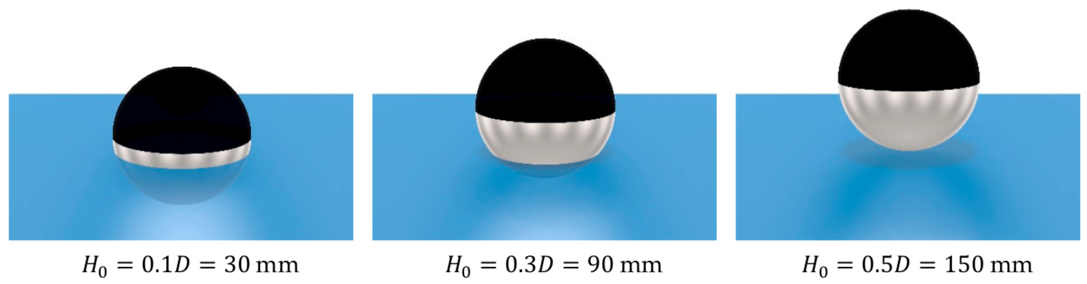
Figure 2.
Photographs of (a) the sphere at equilibrium position in the PWT and (b) the sphere (middle) relative to the three wave gauges (bottom-right), the Qualisys cameras (top-right) and passive absorption elements (top).
Figure 2.
Photographs of (a) the sphere at equilibrium position in the PWT and (b) the sphere (middle) relative to the three wave gauges (bottom-right), the Qualisys cameras (top-right) and passive absorption elements (top).
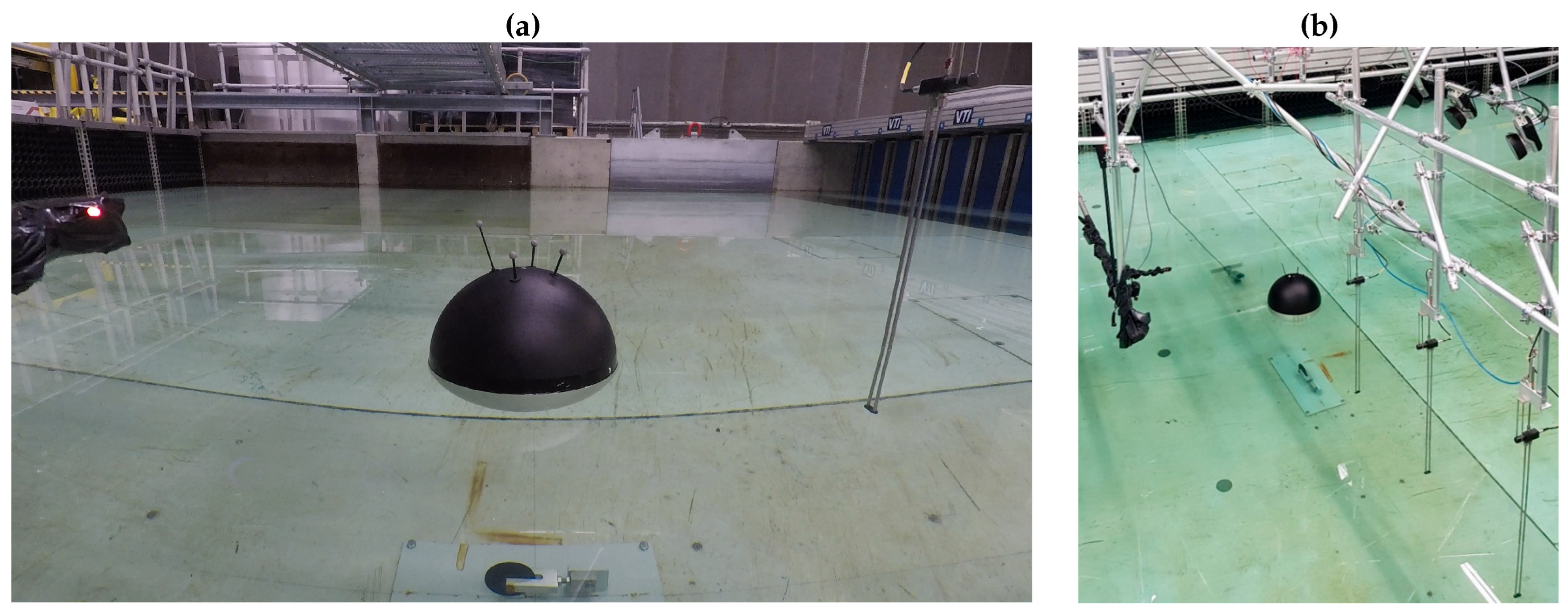
Figure 3.
Test setup and measurements of the PWT. Measurements given in mm. Adapted from [23].
Figure 3.
Test setup and measurements of the PWT. Measurements given in mm. Adapted from [23].
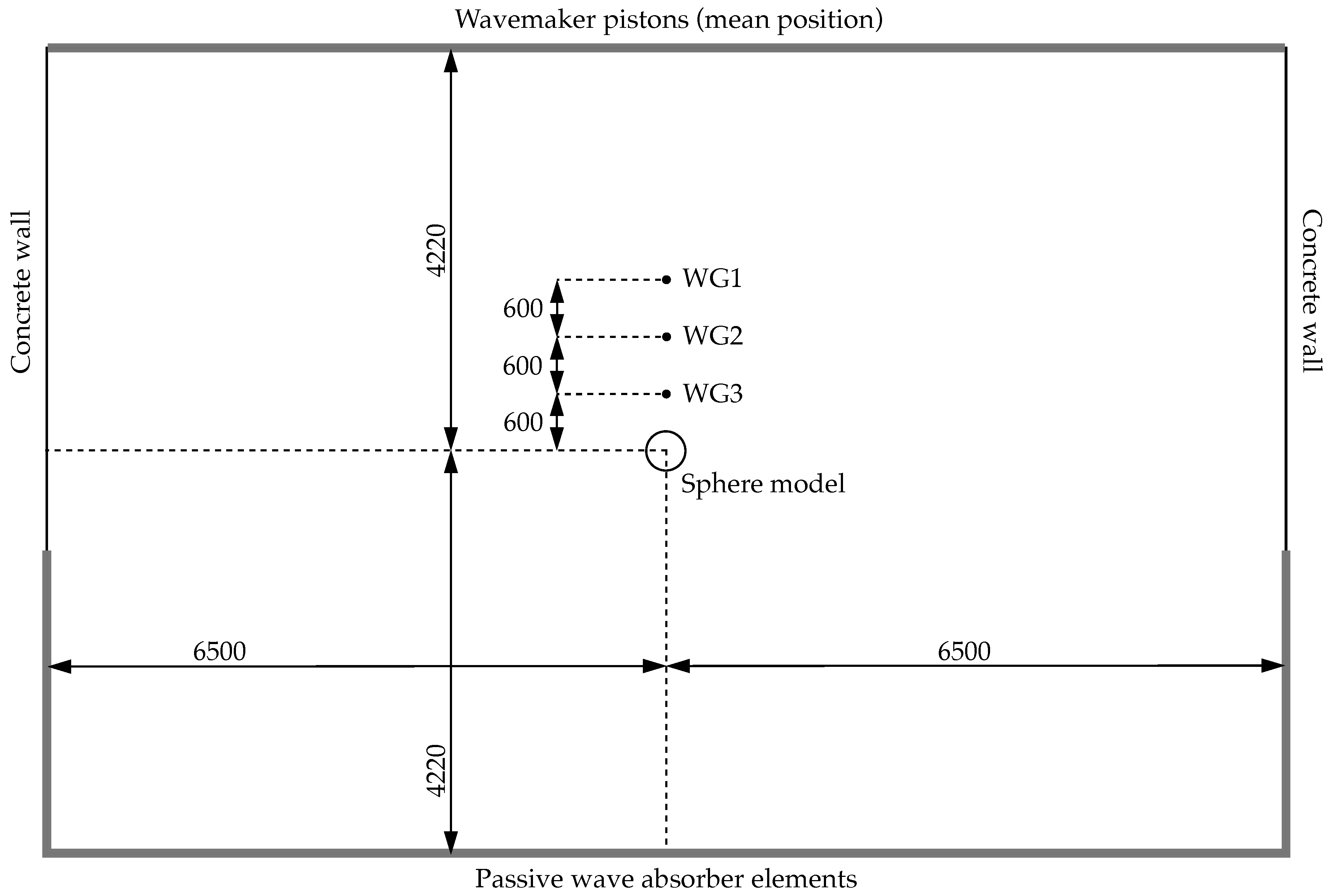
Figure 4.
Normalised heave displacement as a function of normalised time for each drop height .
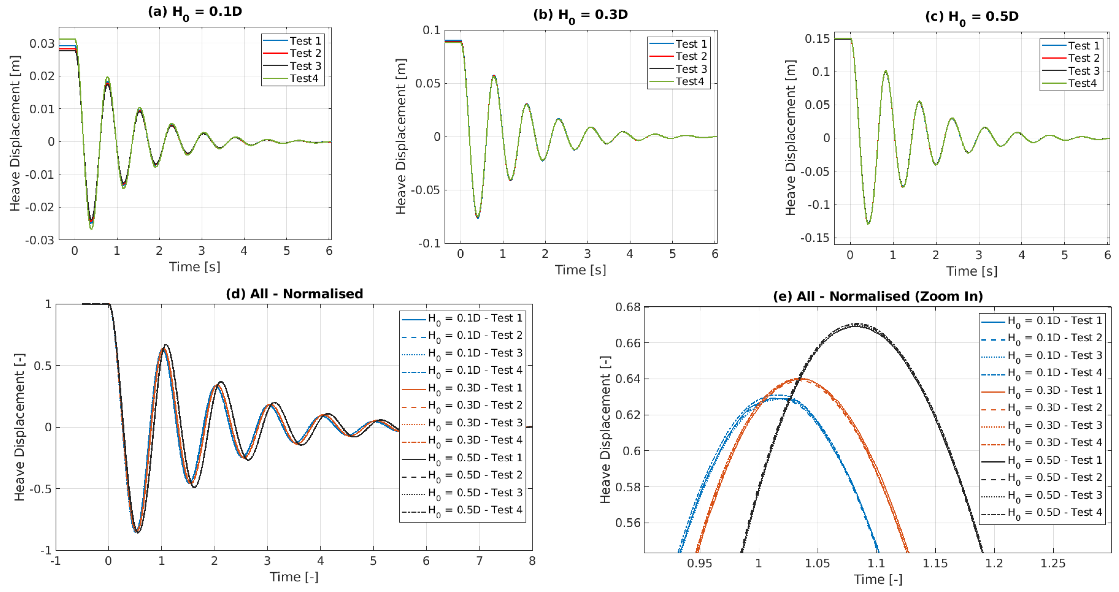
Figure 5.
Normalised free surface elevation as a function of normalised time, measured at the three wave gauges (WG 1-3) for the four repetitions (Tests 1-4), at each drop height .
Figure 5.
Normalised free surface elevation as a function of normalised time, measured at the three wave gauges (WG 1-3) for the four repetitions (Tests 1-4), at each drop height .
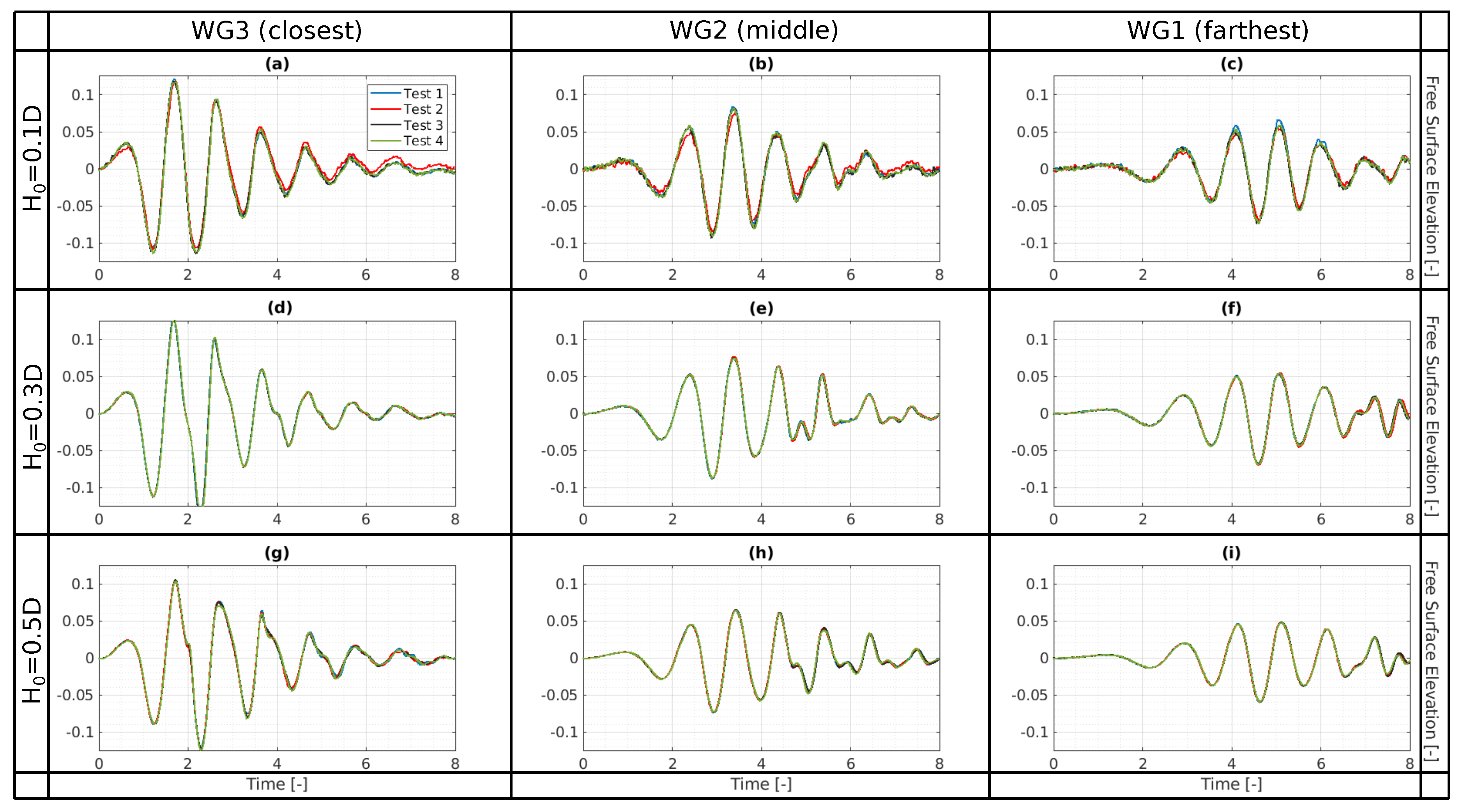
Figure 6.
The axisymmetric wedge. Depicting the one-cell thick, two-dimensional meshing, with cell edges shown in white. The boundaries are labelled in grey and the water volume fraction is shown as red for water and blue for air.
Figure 6.
The axisymmetric wedge. Depicting the one-cell thick, two-dimensional meshing, with cell edges shown in white. The boundaries are labelled in grey and the water volume fraction is shown as red for water and blue for air.
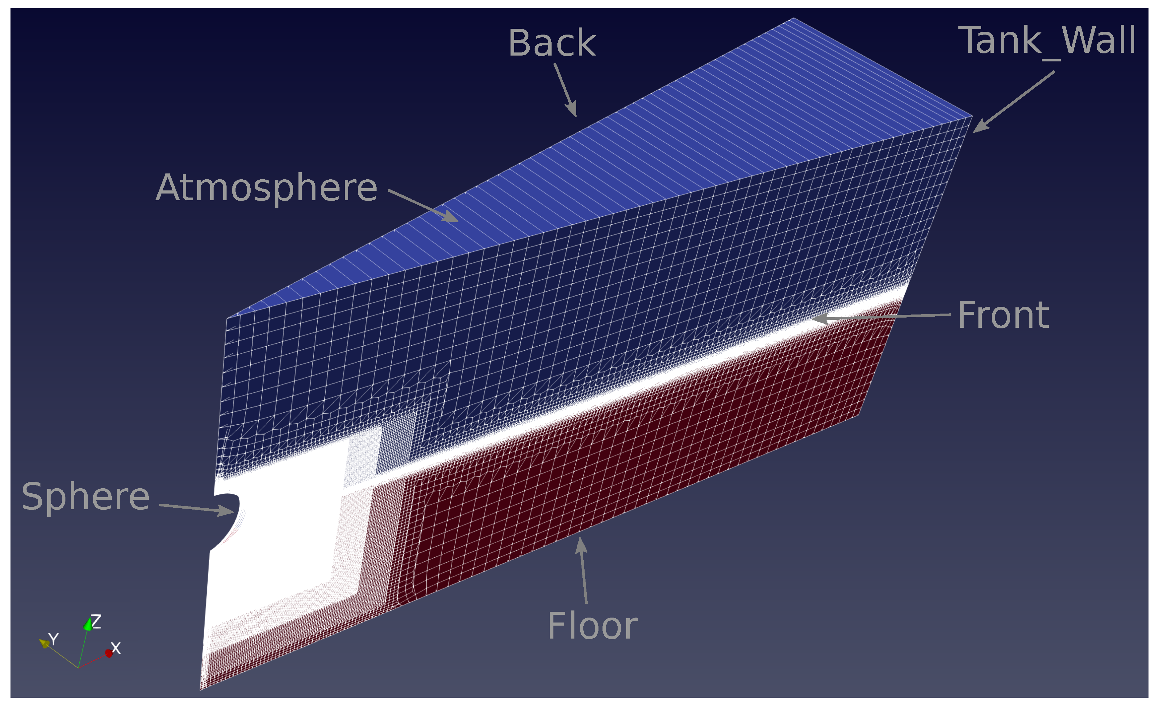
Figure 7.
The mesh setup.
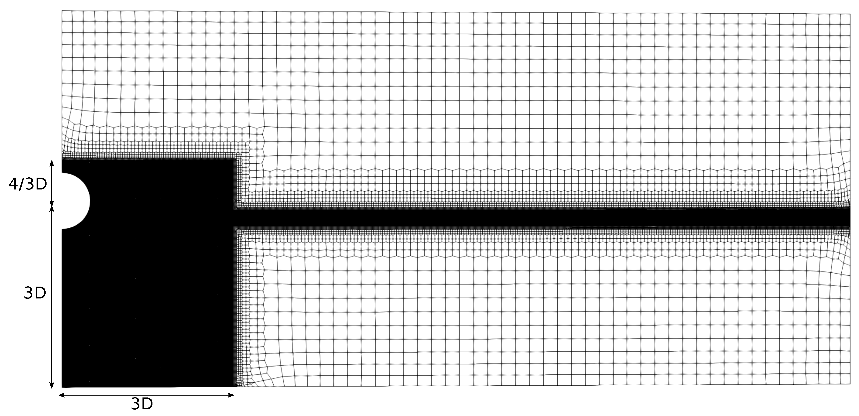
Figure 8.
The mesh refinement levels.
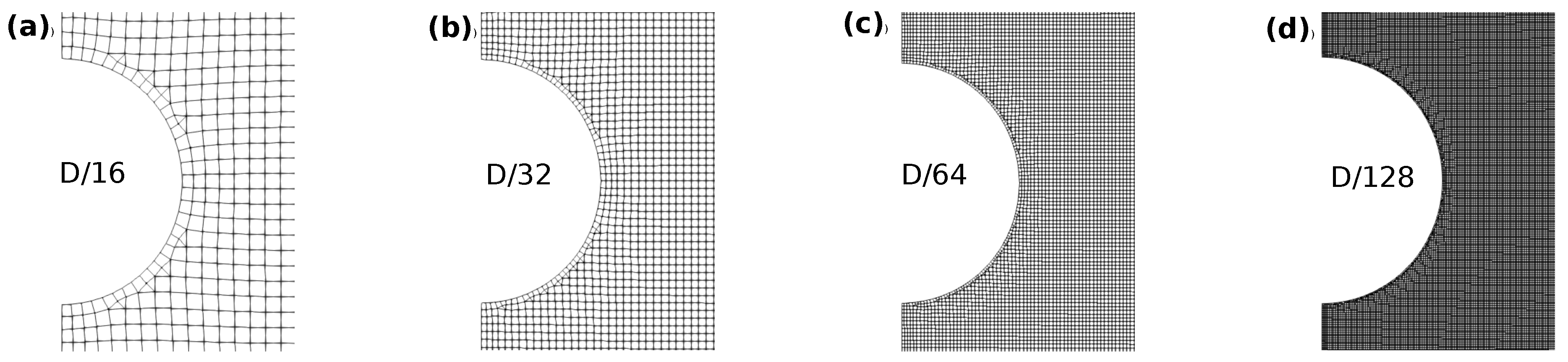
Figure 9.
Converenge study, comparing results from the coarsest and the finest discretisations (spatial and temporal), for both the adaptive and constant time step methods, against the experimental results.
Figure 9.
Converenge study, comparing results from the coarsest and the finest discretisations (spatial and temporal), for both the adaptive and constant time step methods, against the experimental results.
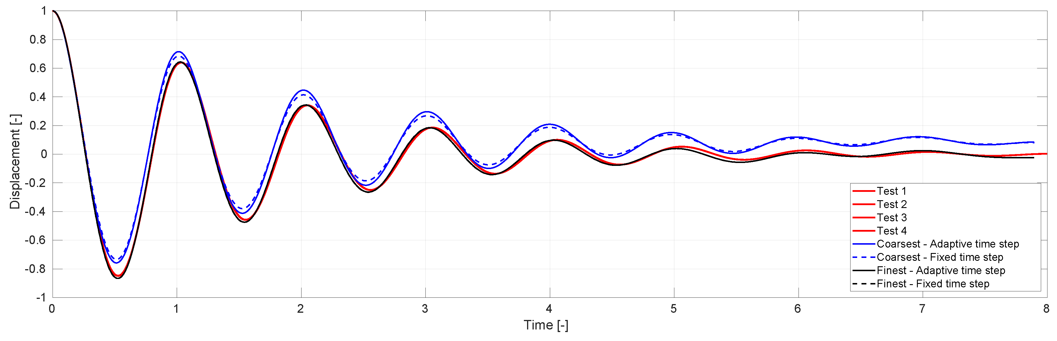
Figure 10.
Converenge study, showing results from four different mesh resolutions, , and five different temporal resolutions .
Figure 10.
Converenge study, showing results from four different mesh resolutions, , and five different temporal resolutions .
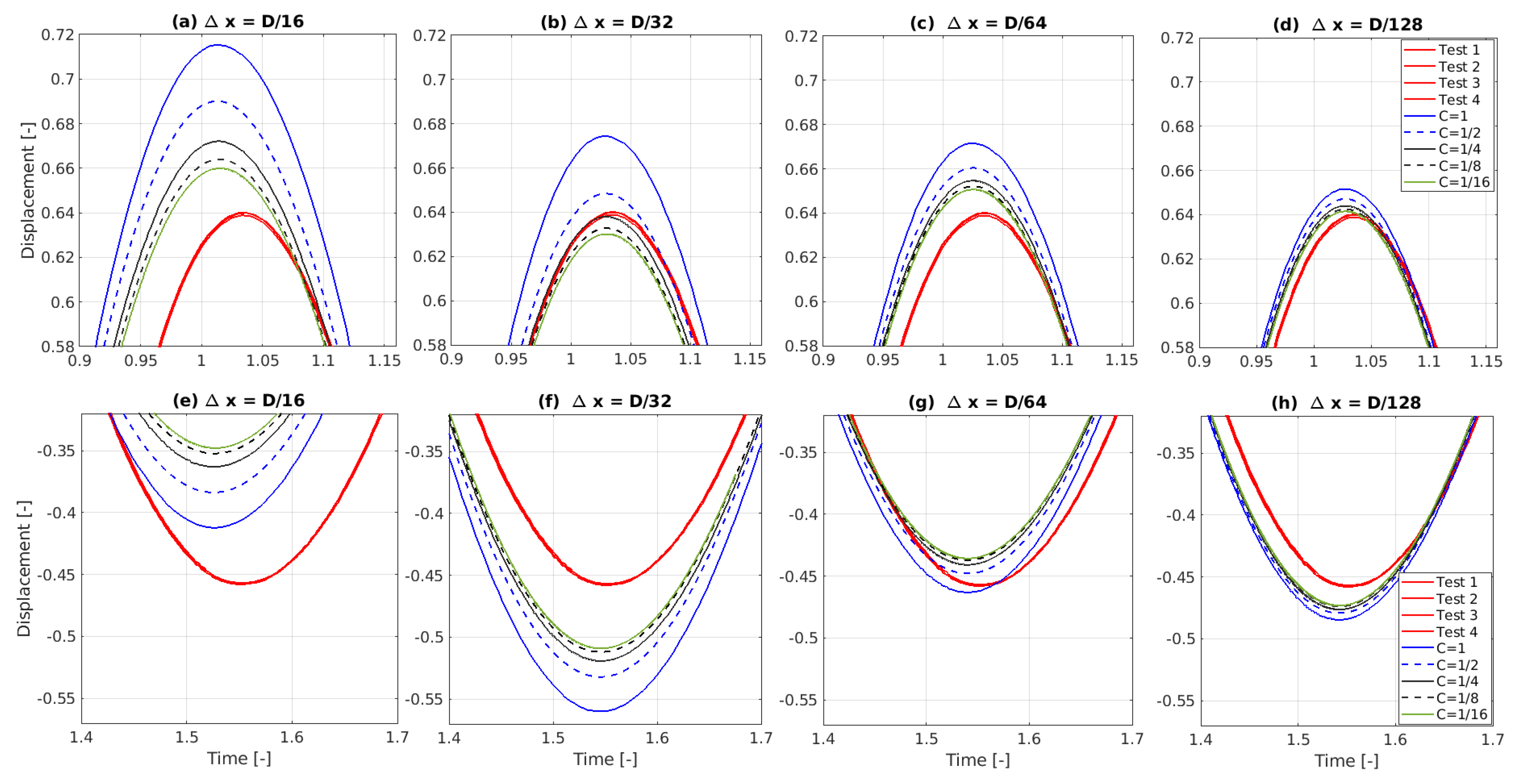
Figure 11.
Converenge study, showing results from four different mesh resolutions, , and five different temporal resolutions .
Figure 11.
Converenge study, showing results from four different mesh resolutions, , and five different temporal resolutions .
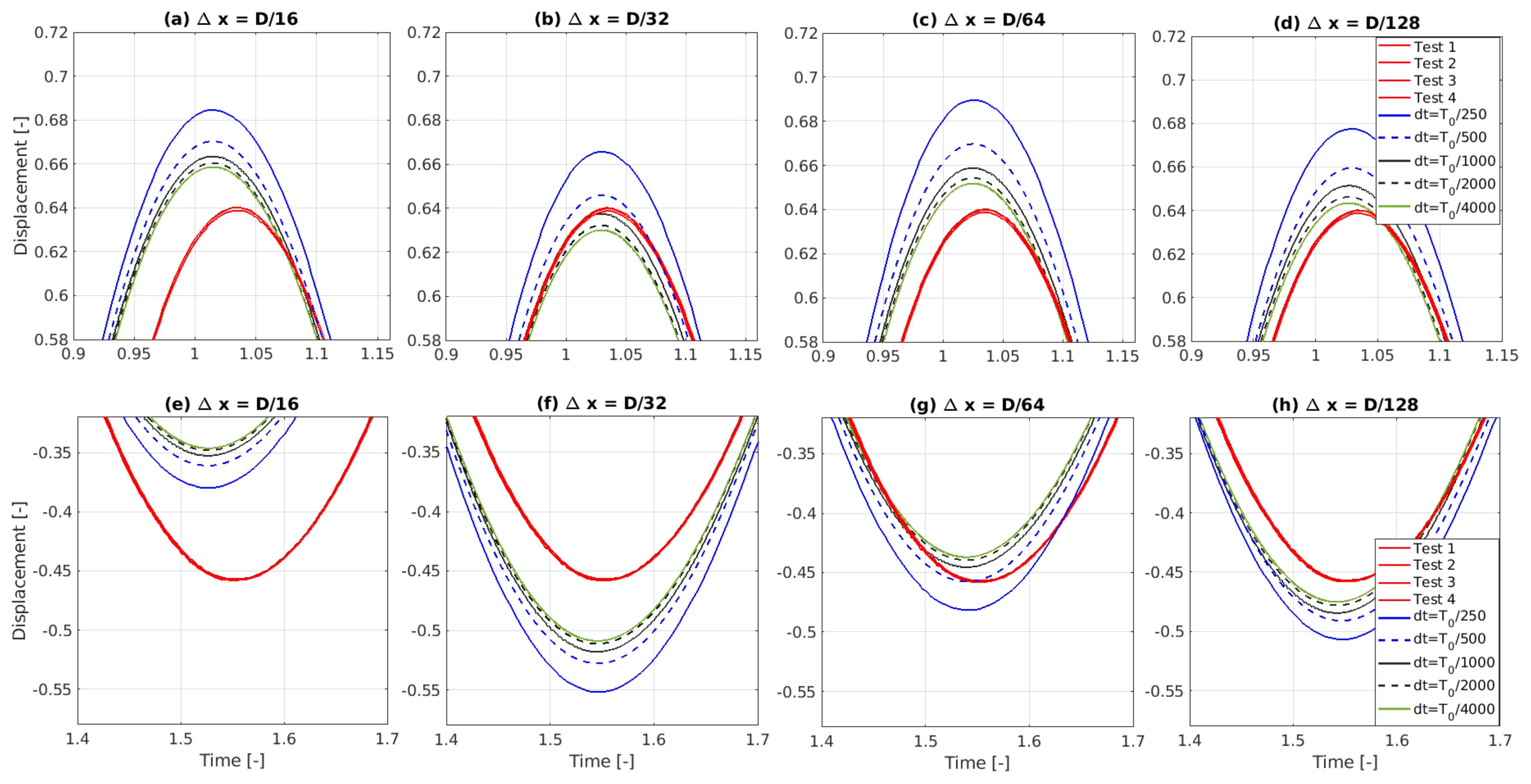
Figure 12.
Convergence study, showing results from five different mesh resolutions, , with a temporal resolution of , at (a) the 1st peak and (b) the 2nd trough. (c) Shows the amplitude of the 1st peak and 2nd trough normalised against the results for the case.
Figure 12.
Convergence study, showing results from five different mesh resolutions, , with a temporal resolution of , at (a) the 1st peak and (b) the 2nd trough. (c) Shows the amplitude of the 1st peak and 2nd trough normalised against the results for the case.
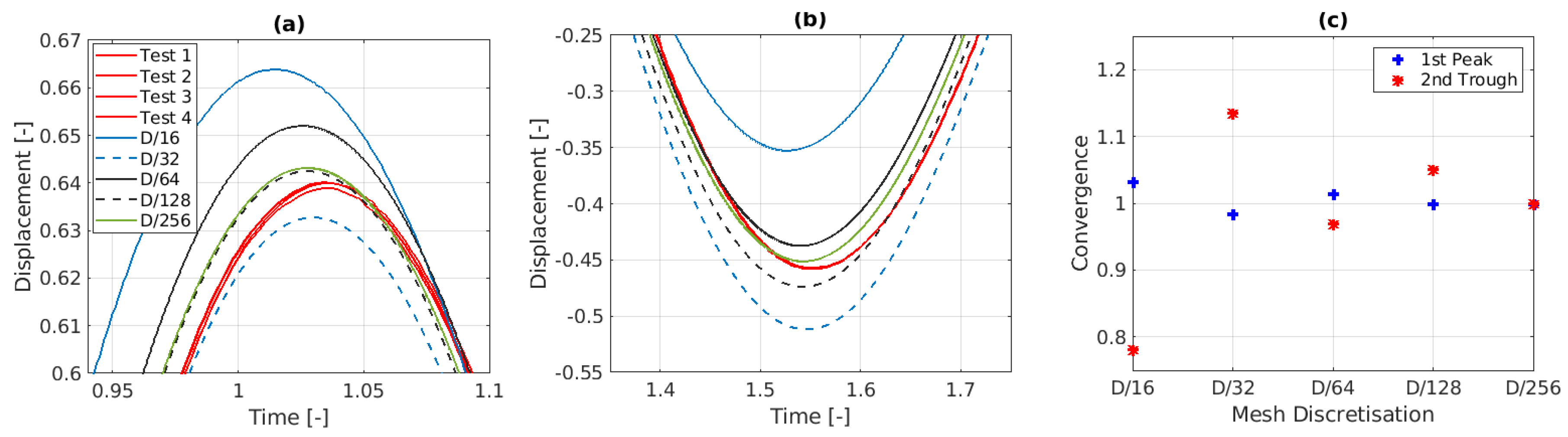
Figure 13.
Comparison of the resulting C at each time step for (a) the coarsest and (b) the finest fixed time step simulations and the resulting value at each time step for (c) the coarsest and (d) the finer adaptive time step simulations, for a mesh with resolution of .
Figure 13.
Comparison of the resulting C at each time step for (a) the coarsest and (b) the finest fixed time step simulations and the resulting value at each time step for (c) the coarsest and (d) the finer adaptive time step simulations, for a mesh with resolution of .

Figure 14.
Results of applying an adaptive time step of compared against an adaptive time step of including a maximum allowable time step of at (a) initial release, (b) 1st peak and (c) 2nd trough.
Figure 14.
Results of applying an adaptive time step of compared against an adaptive time step of including a maximum allowable time step of at (a) initial release, (b) 1st peak and (c) 2nd trough.
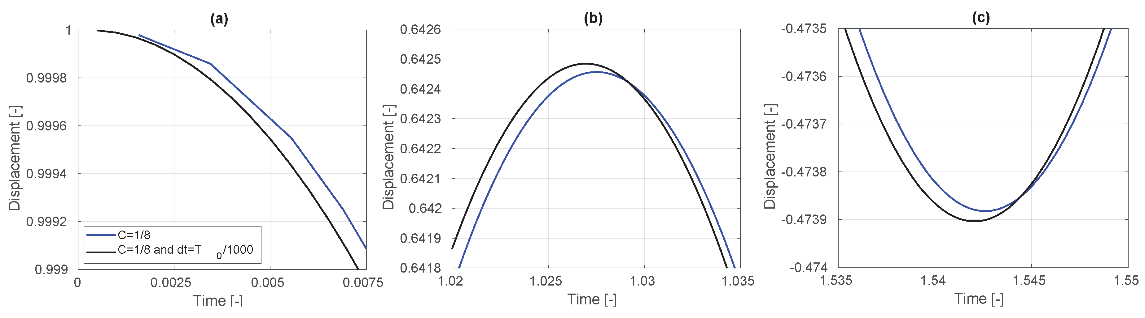
Figure 15.
The mesh for decreasing refinement areas of (a) 3D, (b) 2D and (c) 1D.
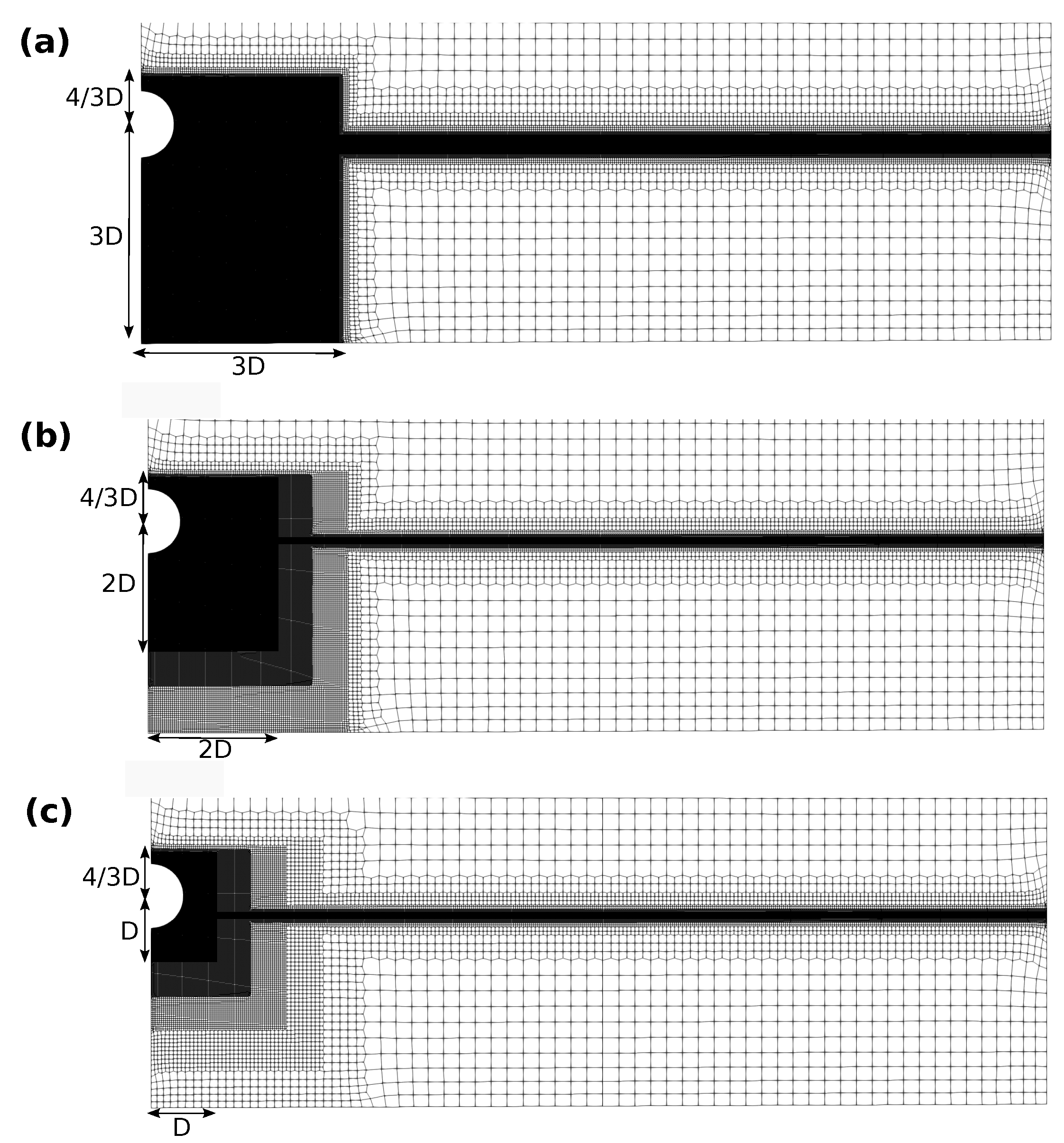
Figure 16.
Convergence study, showing results from five different mesh refinement areas at (a) the 1st peak and (b) the 2nd trough. (c) Shows the accuracy compared to the results for the case.
Figure 16.
Convergence study, showing results from five different mesh refinement areas at (a) the 1st peak and (b) the 2nd trough. (c) Shows the accuracy compared to the results for the case.

Figure 17.
Top view of two A-NWTs with different wedge angles (a) 1° and (b) 8°.
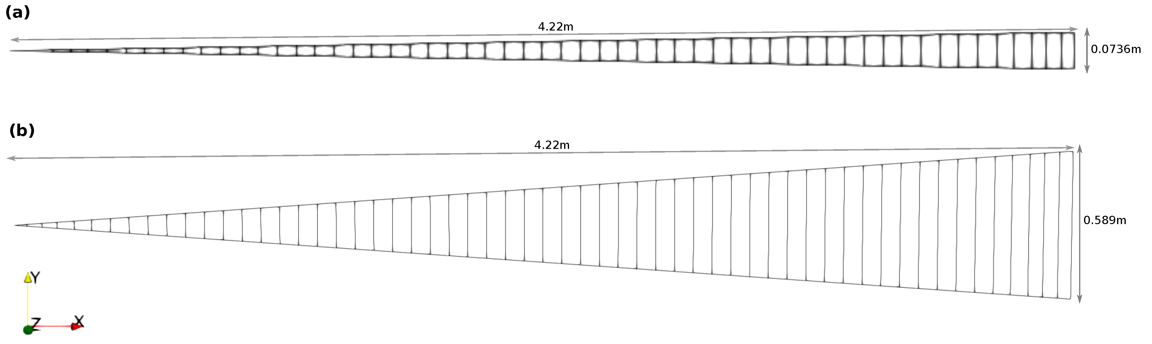
Figure 18.
Comparison of heave decay results for increasing wedge angle: (a) first peak, (b) second trough and (c) relative amplitude of first peak and second trough (normalised against the 0.5 deg results) as a function of wedge angle.
Figure 18.
Comparison of heave decay results for increasing wedge angle: (a) first peak, (b) second trough and (c) relative amplitude of first peak and second trough (normalised against the 0.5 deg results) as a function of wedge angle.
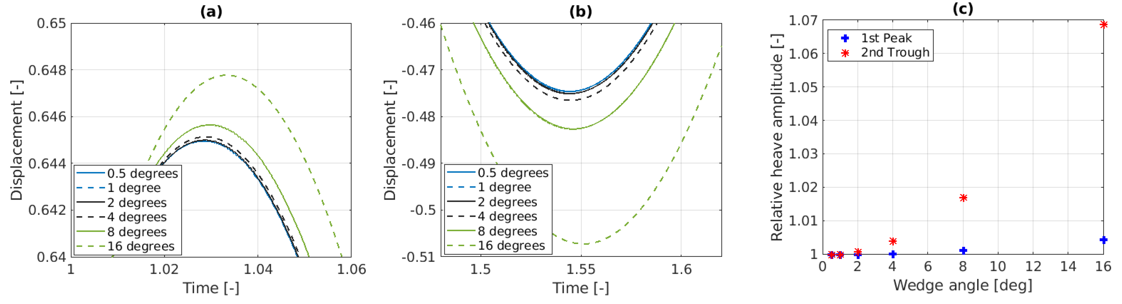
Figure 19.
Comparison of heave decay results for increasing values of the acceleration relaxation parameter: (a) first peak and (b) second trough.
Figure 19.
Comparison of heave decay results for increasing values of the acceleration relaxation parameter: (a) first peak and (b) second trough.
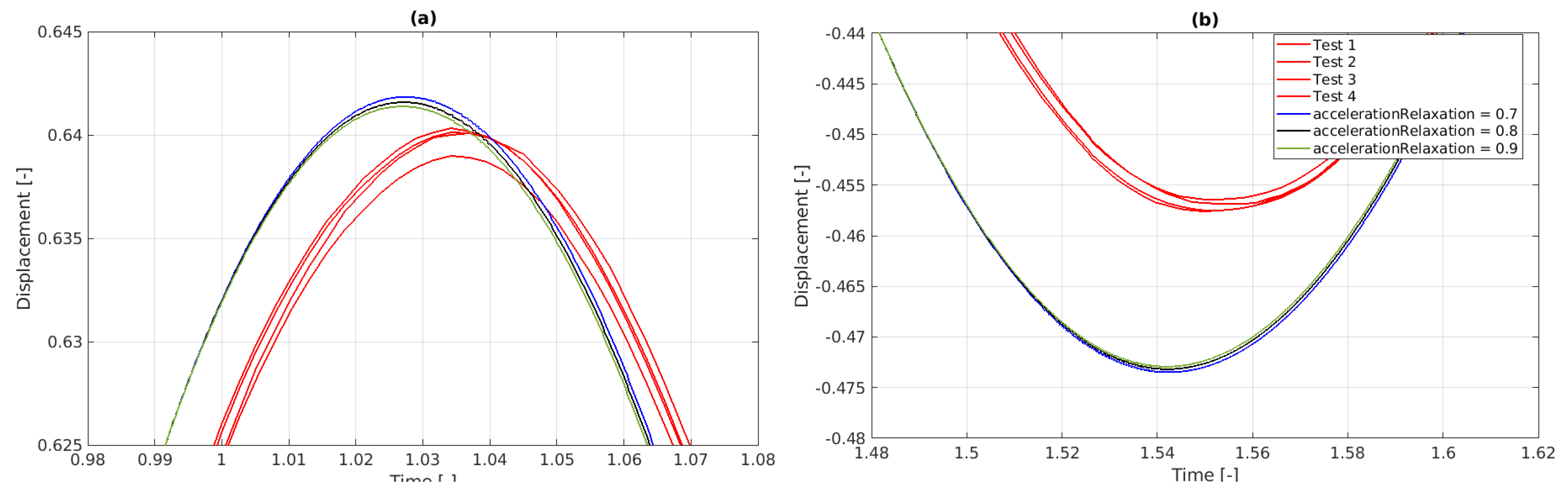
Figure 20.
Comparison of heave decay results for increasing number of PIMPLE iterations: (a) first peak and (b) second trough.
Figure 20.
Comparison of heave decay results for increasing number of PIMPLE iterations: (a) first peak and (b) second trough.
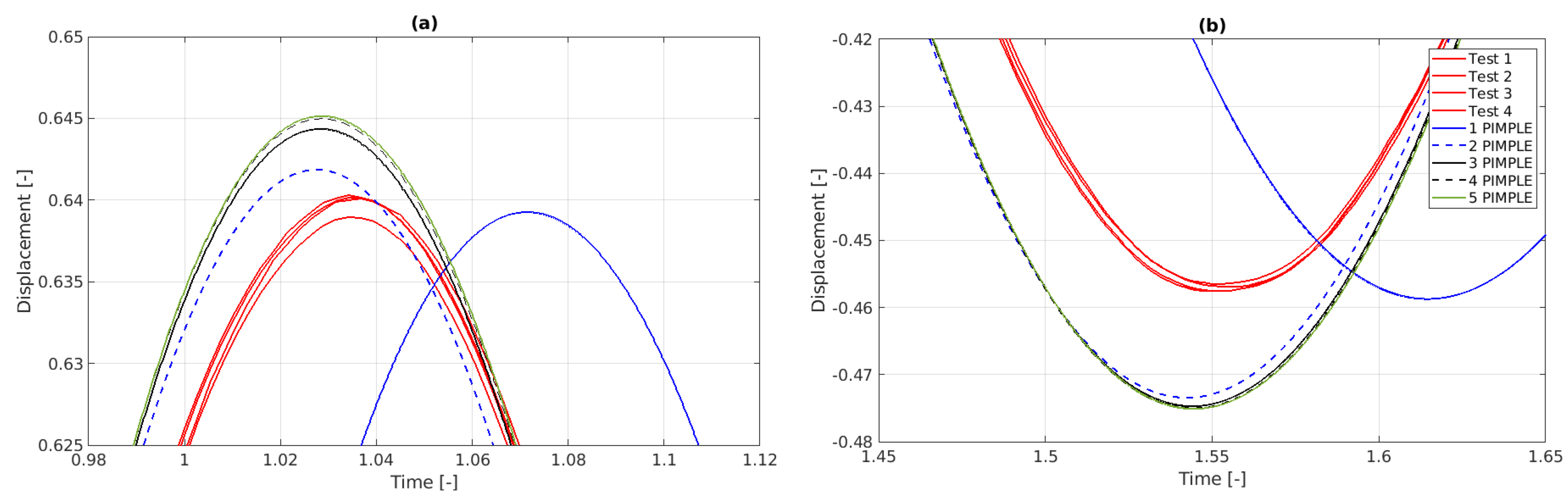
Figure 21.
Comparison of heave decay results for increasing PIMPLE iterations with mesh motion update on each inner PIMPLE loop: (a) first peak and (b) second trough.
Figure 21.
Comparison of heave decay results for increasing PIMPLE iterations with mesh motion update on each inner PIMPLE loop: (a) first peak and (b) second trough.
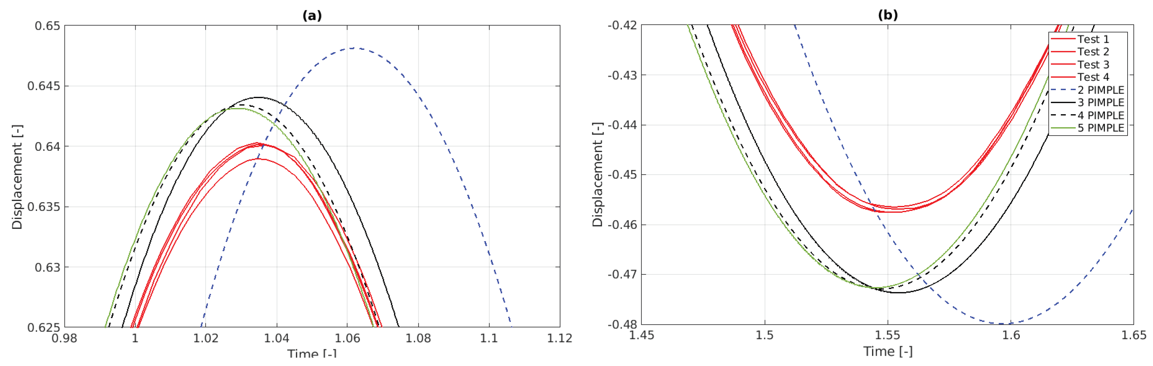
Figure 22.
Comparison of the results from previous laminar simulations, with three PIMPLE iterations and mesh motion, to including turbulence model with default values and for double of the default values.
Figure 22.
Comparison of the results from previous laminar simulations, with three PIMPLE iterations and mesh motion, to including turbulence model with default values and for double of the default values.
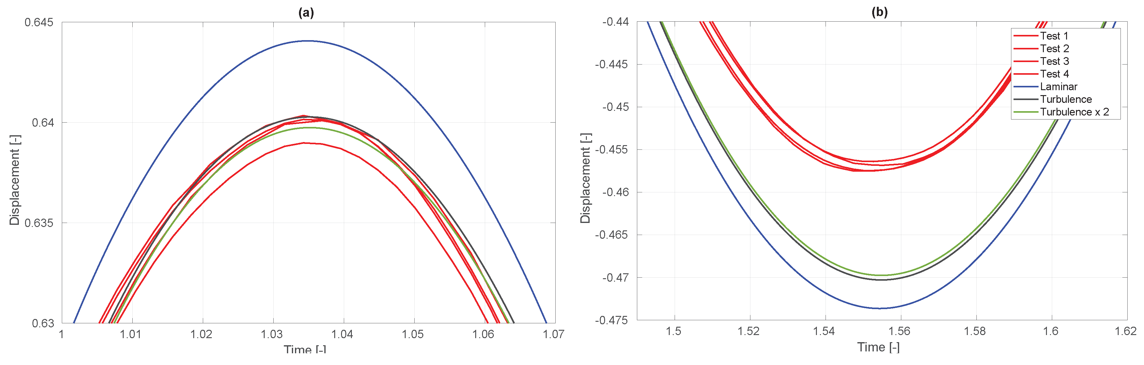
Figure 23.
Post-process snapshots of the alpha.water (left column) and p_rgh (right column) from the A-NWT simulations at different time instances (rows).
Figure 23.
Post-process snapshots of the alpha.water (left column) and p_rgh (right column) from the A-NWT simulations at different time instances (rows).
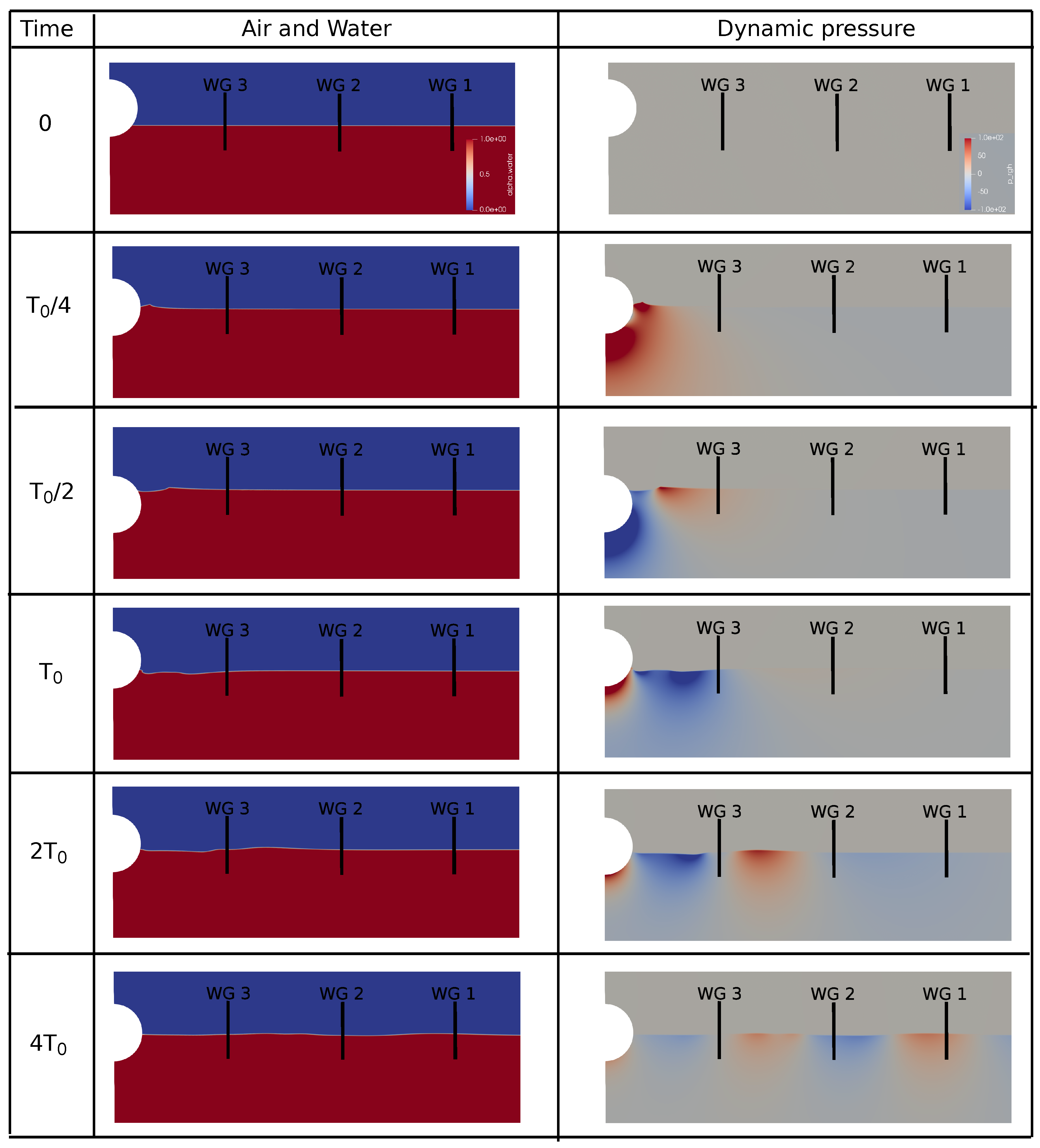
Figure 24.
Comparison of the free surface elevation measured at the wave gauges in the PWT and A-NWT.
Figure 24.
Comparison of the free surface elevation measured at the wave gauges in the PWT and A-NWT.
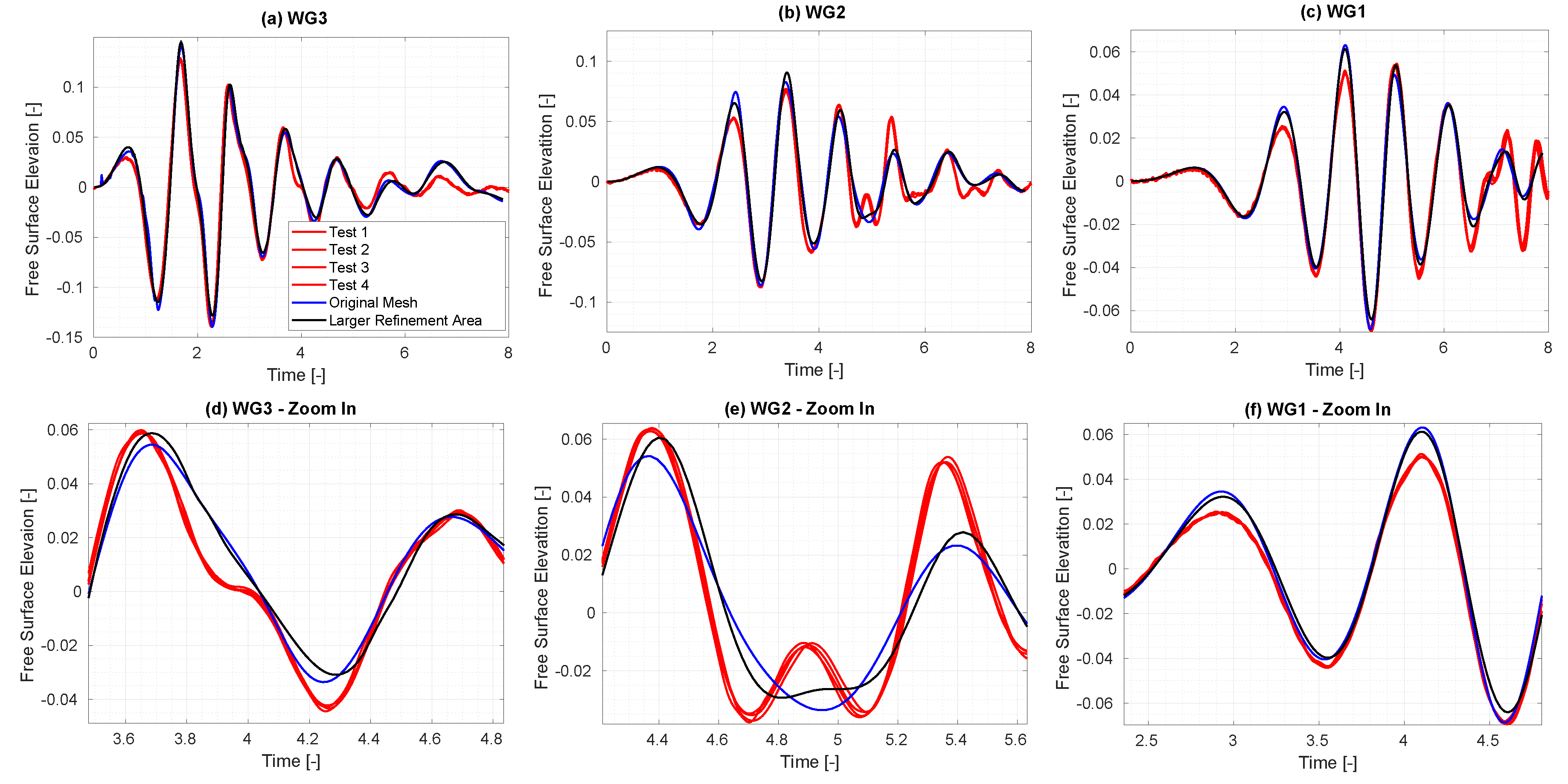
Figure 25.
Screenshot of the mesh at (left) and (right) for the original mesh (top) and for the updated mesh with a larger refinement area around the free surface to accomodate the mesh motion (bottom).
Figure 25.
Screenshot of the mesh at (left) and (right) for the original mesh (top) and for the updated mesh with a larger refinement area around the free surface to accomodate the mesh motion (bottom).
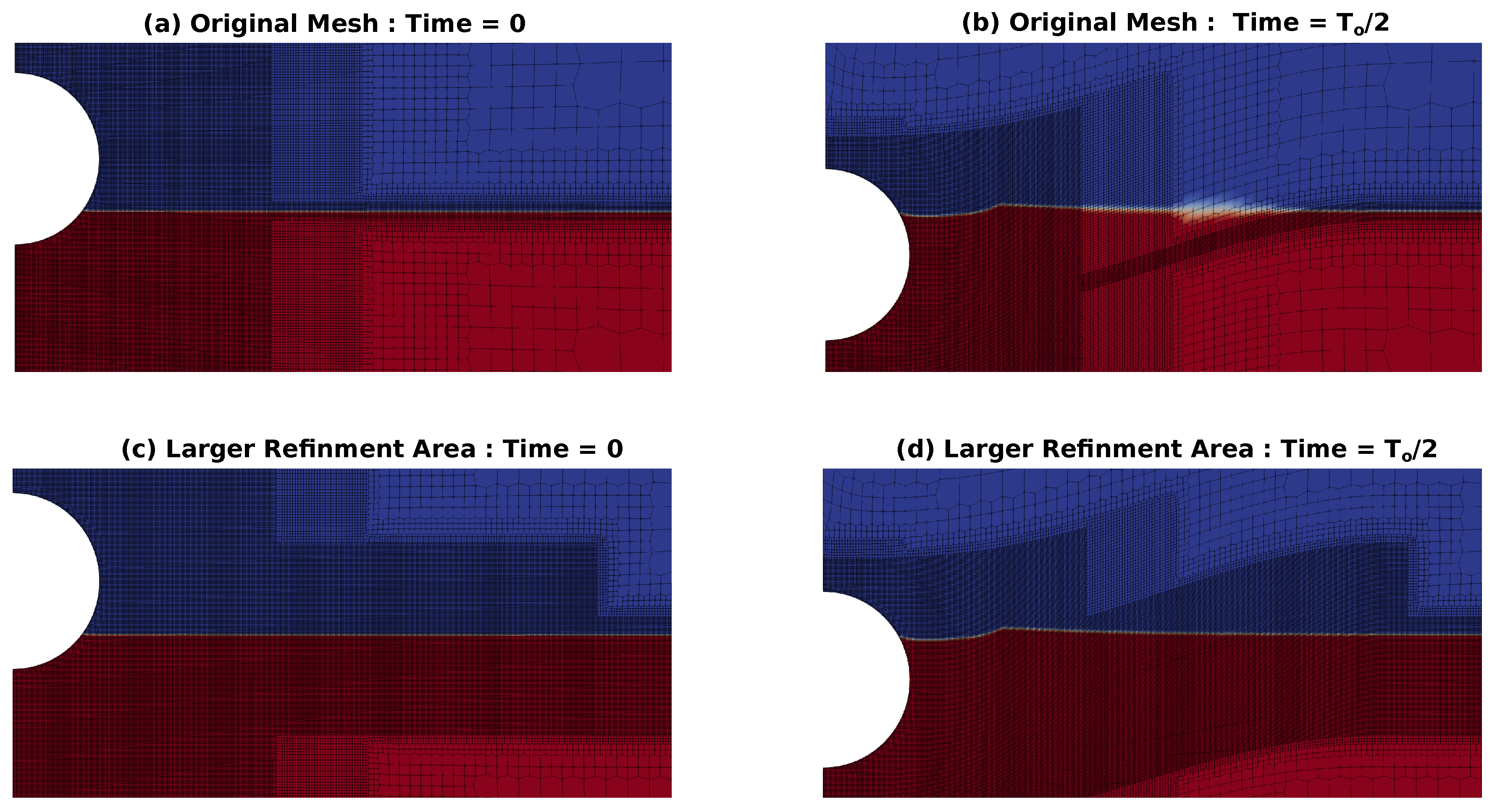
Figure 26.
Comparison of the PWT and A-NWT results for an initial drop height, .
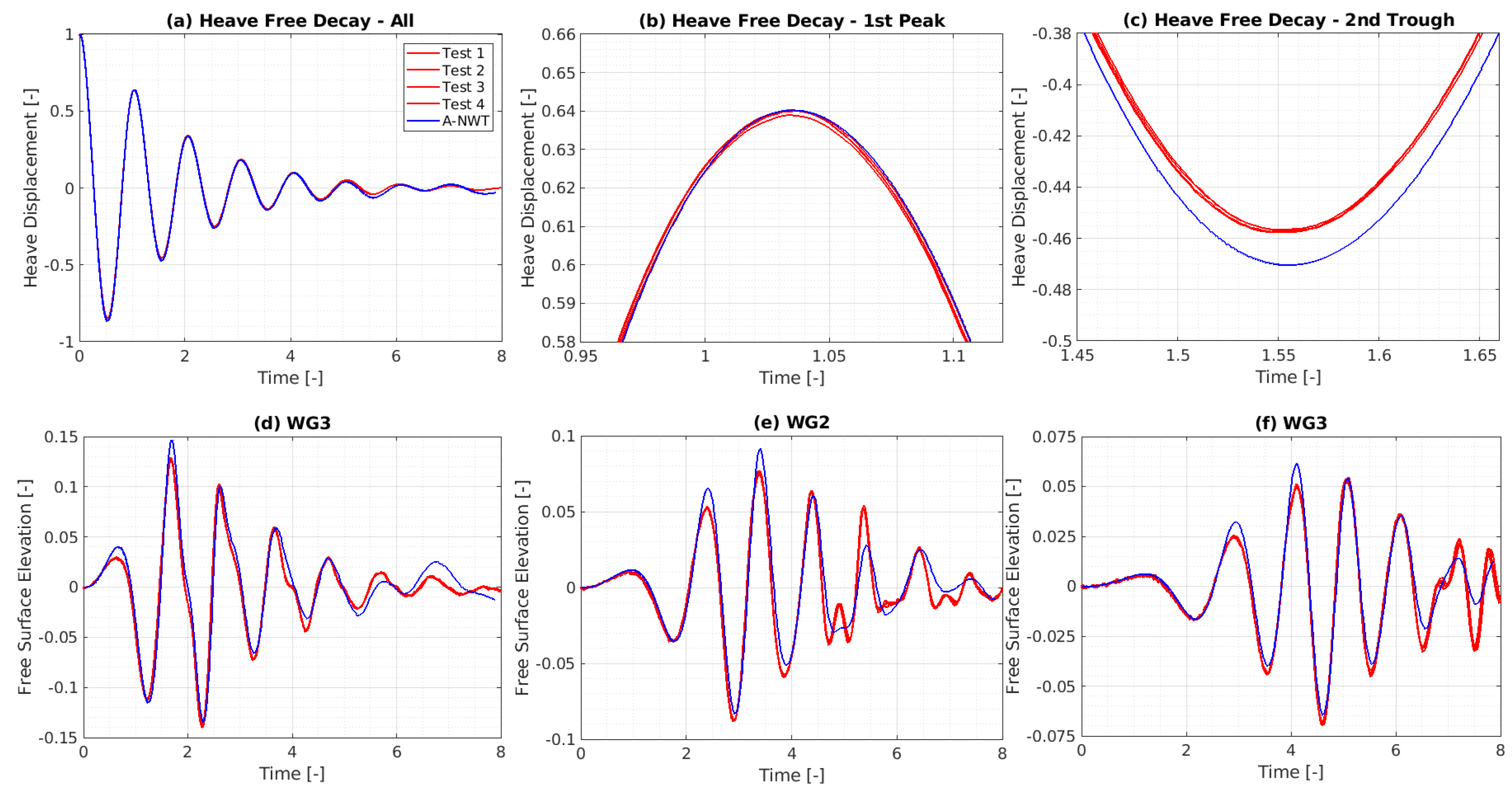
Figure 27.
Comparison of the PWT and A-NWT results for an initial drop height, .
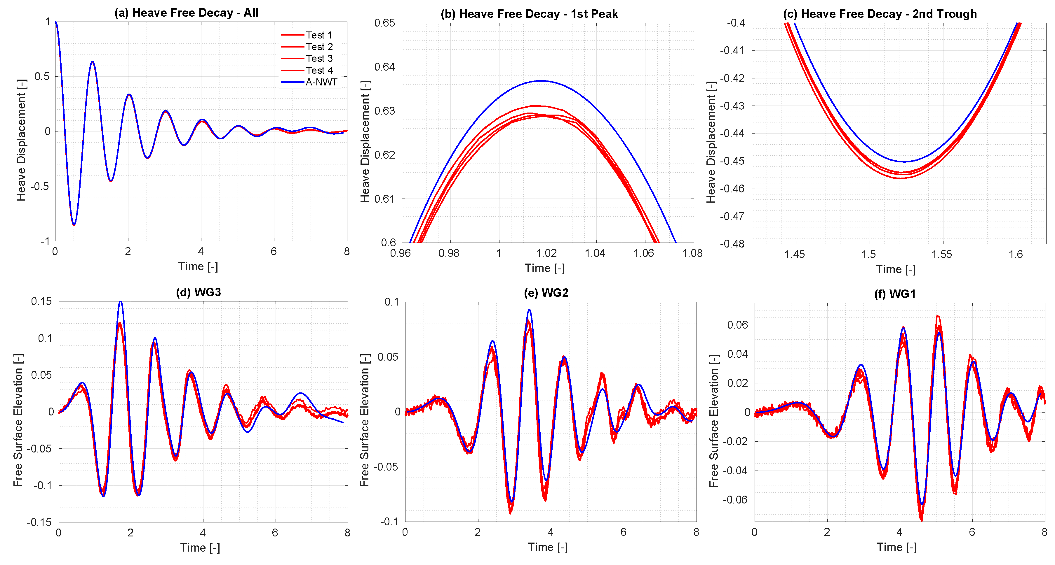
Figure 28.
Comparison of the PWT and A-NWT results for an initial drop height, .
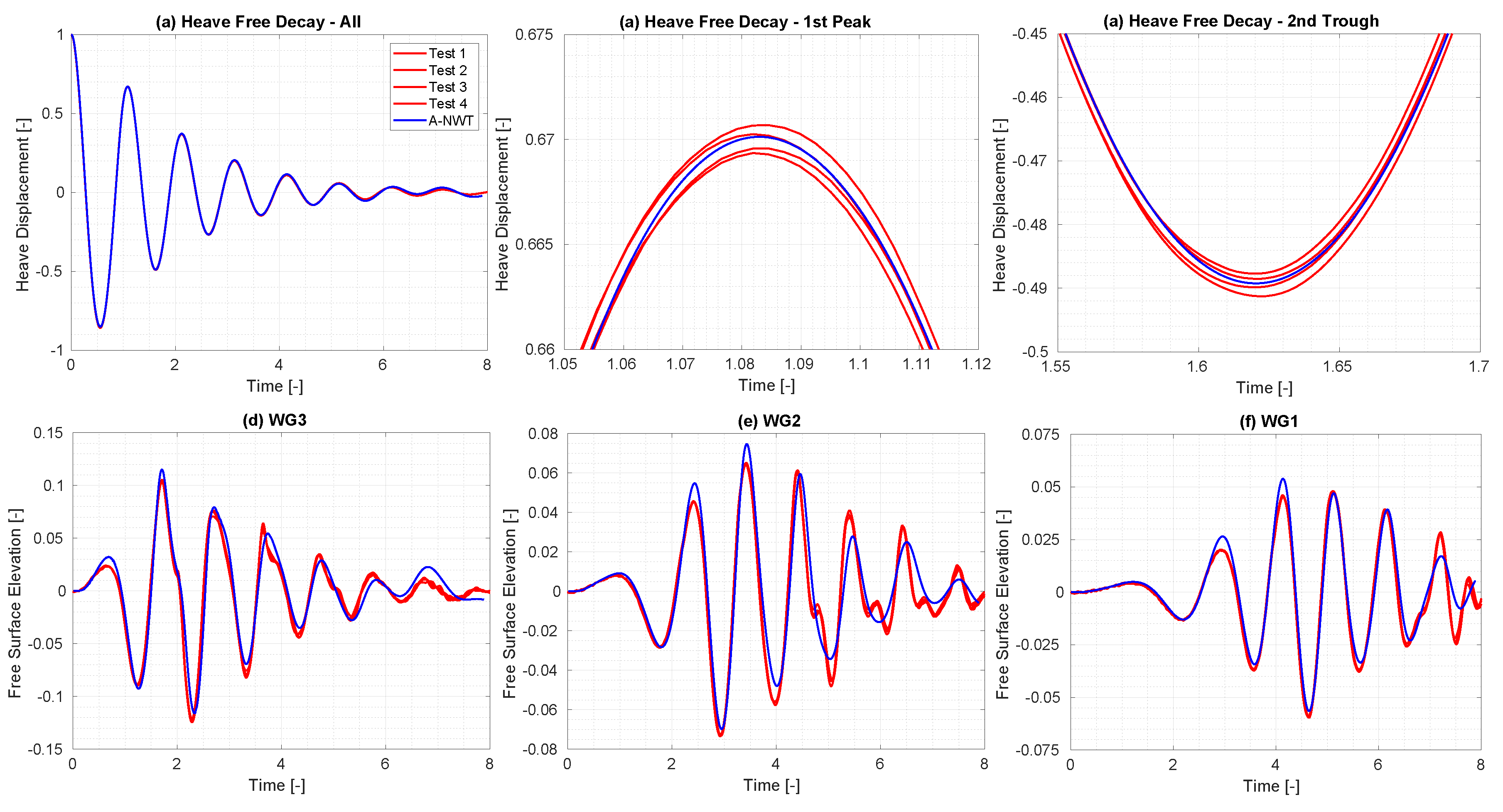

Table 1.
Physical parameters and their values in the study.
| Parameter | D | m | CoG | g | d | ||
| Unit | mm | kg | mm | m/ | mm | kg/ | mm |
| Value | 300 | 7.056 | (0, 0, -34.8) | 9.82 | {30, 90, 150} | 998.2 | 900 |
Table 2.
The names, types and various conditions for the A-NWT boundaries.
| Name | Type | alpha.water | point-Displacement | p_rgh | U |
|---|---|---|---|---|---|
| Front | Wedge | wedge | wedge | wedge | wedge |
| Back | Wedge | wedge | wedge | wedge | wedge |
| Floor | Stationary Wall | zeroGradient | fixedValue | fixedFlux-Pressure | fixedValue |
| Atmosphere | Inlet/Outlet | inletOutlet | fixedValue | totalPressure | pressureInlet-OutletVelocity |
| Tank_Wall | Stationary Wall | zeroGradient | fixedValue | fixedFlux-Pressure | fixedValue |
| Sphere | Moving Wall | zeroGradient | calculated | fixedFlux-Pressure | movingWall-Velocity |
Table 3.
Simulation Parameters for the A-NWT
| Parameter | Value |
|---|---|
| D/128 | |
| < and C<1/8 | |
| Mesh Refinement Area | 1.5D + free surface in mesh motion area |
| Wedge Angle | 2° |
| PIMPLE settings | 3 iterations + move mesh on inner loop |
| Turbulence | – default values |
| accelerationRelaxation | 0.7 |
Disclaimer/Publisher’s Note: The statements, opinions and data contained in all publications are solely those of the individual author(s) and contributor(s) and not of MDPI and/or the editor(s). MDPI and/or the editor(s) disclaim responsibility for any injury to people or property resulting from any ideas, methods, instructions or products referred to in the content. |
© 2024 by the authors. Licensee MDPI, Basel, Switzerland. This article is an open access article distributed under the terms and conditions of the Creative Commons Attribution (CC BY) license (http://creativecommons.org/licenses/by/4.0/).
Copyright: This open access article is published under a Creative Commons CC BY 4.0 license, which permit the free download, distribution, and reuse, provided that the author and preprint are cited in any reuse.


