
Submitted:
20 August 2024
Posted:
20 August 2024
You are already at the latest version
Abstract
With the development of Global Navigation Satellite Systems (GNSS), the quality and anti-jamming capability of satellite navigation signals are crucial. Binary Offset Carrier (BOC) modulation faces issues of false locking due to multi-peak ambiguity in its autocorrelation function, limiting its application. This paper examines FH-BOC modulation, which integrates BOC with frequency hopping technology, significantly improving anti-jamming, anti-multipath performance, and spectral efficiency. To meet the high dynamic tracking demands of FH-BOC signals, this study explores three types of carrier tracking loops: the traditional second-order frequency-locked loop assisted a third-order phase-locked loop, a linear Kalman filter-based tracking algorithm, and an adaptive Kalman filter-based tracking algorithm. A composite code tracking loop is also proposed. Simulations show that the adaptive Kalman filter algorithm achieves high-precision carrier tracking in dynamic environments and quickly converges during transitions. The composite code tracking loop, aided by the carrier loop, ensures precise synchronization of pseudocode and frequency-hopping subcarrier phases, demonstrating the superior performance of FH-BOC modulation in dynamic environments.
Keywords:
GNSS
; FH-BOC
; high dynamic tracking
; carrier tracking loop
; adaptive Kalman filter
; composite code loop
1. Introduction
As the Global Navigation Satellite System (GNSS) evolves, the increasing number of satellites amplifies the importance of signal quality and anti-jamming capabilities [1,2]. Various modulation techniques have thus been extensively studied and applied. Initially, Binary Phase-Shift Keying (BPSK-R) was the dominant modulation method [3]. However, as demands grew, particularly in complex electromagnetic environments, the limitations of BPSK in resisting interference and multipath effects became evident. To address these issues, Binary Offset Carrier (BOC) modulation was introduced [4,5], offering split-spectrum characteristics that allow multiple satellite signals to share a carrier frequency without interference, along with enhanced precision in ranging and positioning. Despite these advantages, the BOC signal’s autocorrelation function’s multiple peaks can cause tracking errors, often requiring complex receiver-side solutions [6,7].
To improve GNSS signal performance, advanced BOC modulation schemes like MBOC and AltBOC [8,9], have been developed, providing better spectrum efficiency, and anti-jamming performance. However, these enhancements increase the complexity of the signal reception loop. Frequency-Hopping BOC (FH-BOC) modulation introduces a novel approach by combining BOC with frequency-hopping techniques, improving anti-jamming and multipath resistance while maintaining constant-envelope modulation. FH-BOC also suppresses secondary autocorrelation peaks, eliminating the multi-peak ambiguity inherent in BOC modulation [10,11,12].
Research on high-dynamic tracking algorithms for FH-BOC is in its infancy. Traditional BOC tracking methods typically use Delay Lock Loops (DLL) [13] for code phase tracking and classical Phase-Locked Loop (PLL) or Frequency-Locked Loop (FLL) structures [14] for carrier tracking. However, these methods are inadequate for high-dynamic environments. Inertial navigation systems (INS) have been integrated to assist tracking loops in such conditions [15], offering innovative solutions, though error accumulation in INS and system instability remain challenges [16,17,18,19].
The Kalman filter, a widely used recursive algorithm in signal processing [20], is effective in optimizing carrier component estimation in high-dynamic environments. Variants like Linear [21,22], Extended [23,24], and Unscented Kalman filters [25] are already applied in navigation signal tracking. Applying Kalman filtering to FH-BOC high-dynamic carrier tracking offers significant potential. Additionally, the absence of multi-peak ambiguity in FH-BOC allows for a more straightforward design of the code tracking loop, utilizing the correlation between the ranging code and the frequency-hopping carrier. This can be treated as a composite code, enabling simultaneous tracking of both elements, further demonstrating FH-BOC’s advantages.
2. Overview of the FH-BOC Modulation Scheme
2.1. FH-BOC Signal Model
FH-BOC modulation can be considered a generalized form of BOC modulation. It replaces the constant frequency binary offset subcarrier used in conventional BOC modulation with a randomly frequency-hopping binary offset subcarrier, resulting in the FH-BOC signal. This frequency-hopping subcarrier approach retains the continuity of the carrier phase of the transmitted signal, thereby preserving the carrier-based velocity measurement capability. Simultaneously, the signal maintains the BOC modulation form within each frequency hop, enhancing compatibility with traditional BOC modulation. The time-domain waveform of the FH-BOC modulation can be expressed as follows:
Where: represents the message bits to be transmitted, denotes the pseudorandom code, indicates the waveform of the frequency-hopping square wave subcarrier, is the duration of a single spreading code chip, and represents the frequency of the current frequency-hopping subcarrier. Typically, can be defined in two forms: sine phase and cosine phase, as follows:
From the above analysis, it is evident that describing a complete FH-BOC modulation scheme requires the following five parameters: represents the maximum frequency of the binary offset subcarrier’s frequency hopping, denotes the minimum frequency of the frequency hopping, indicates the frequency step of the subcarrier’s hopping, is the pseudorandom code rate, and represents the reciprocal of the square wave subcarrier’s hopping period. Typically, these parameters are integer multiples of 1.023MHz.
Using the standard notation in the field of navigation, the shorthand is used to represent a complete FH-BOC modulation scheme, where , , , , , denotes the reference frequency. Accordingly, the set of frequency-hopping frequencies for the FH-BOC modulation is , where .
The complete FH-BOC signal generation process is shown in Figure 1.
2.2. The Autocorrelation Function and Power Spectral Density of FH-BOC
According to the definition of the autocorrelation function, the autocorrelation function of FH-BOC signals can be expressed as follows:
To simplify the calculations, can be written as:
In this equation, represents the pseudocode symbol modulated by data bits. Further derivation yields:
Here, represents the autocorrelation function of the spreading code. Assuming an infinite period and ideal autocorrelation, the equation simplifies to:
Since the FH-BOC modulated signal conforms to the definition of a generalized cyclostationary process, the derivation yields [10]:
(1)The autocorrelation function expression for the sine-phase FH-BOC modulated signal is:
In this equation, where , , is defined as:
(2)The expression for the autocorrelation function of the cosine-phase FH-BOC modulated signal is given by:
Where: represents the floor function.
According to the Wiener-Khinchin theorem, a signal’s autocorrelation function and power spectral density are a Fourier transform pair, thus:
(1) The power spectral density of a sin-phase FH-BOC modulated signal is:
(2) The power spectral density of a cos-phase FH-BOC modulated signal is:
Figure 2 presents the autocorrelation functions and power spectral densities of FH-BOC(31,1,1,1,1) modulated signals with sin-phase and cos-phase frequency-hopping square wave subcarriers. For constant modulation parameters, the cosine-phase subcarrier demonstrates a more confined autocorrelation function and a more pronounced spectral density splitting compared to the sine-phase subcarrier.
Figure 3 compares the autocorrelation functions of FH-BOC modulated signals with conventional direct-sequence spread spectrum (DSSS) signals and BOC modulated signals. The figure indicates that FH-BOC modulation exhibits a sharper main peak in its autocorrelation function, while the side lobes are suppressed, mitigating the multipath ambiguity often seen in conventional BOC modulation.
Figure 4 compares the power spectral density of FH-BOC modulated signals with conventional modulation schemes. The figure illustrates that FH-BOC modulation further expands the signal bandwidth through subcarrier frequency hopping, enhancing both anti-jamming and multipath resistance. Additionally, FH-BOC modulation retains the spectral splitting characteristic of BOC modulation, shifting signal energy from the center to higher frequencies. This shift improves ranging accuracy and increases the spectral separation of the signal at the center of the frequency band.
3. High-Dynamic Tracking Algorithms
A global navigation satellite system (GNSS) signal receiver typically employs a carrier tracking loop for carrier synchronization and a delay lock loop (DLL) for code synchronization. These loops collaborate to accurately determine the carrier phase, Doppler shift, and pseudocode phase offset of the received signal. This paper introduces high-dynamic tracking algorithms for FH-BOC modulation, focusing on carrier and code tracking loops.The carrier tracking loop section discusses classical designs, including a second-order frequency lock loop (FLL) assisting a third-order phase lock loop (PLL), as well as designs based on linear and adaptive Kalman filter algorithms. The code tracking section highlights the composite code loop tracking algorithm, which treats the pseudocode XORed with the frequency-hopped subcarrier as a composite pseudocode.
Before introducing these tracking algorithms, it is essential to understand the high-dynamic environment. According to the high-dynamic signal model from the Jet Propulsion Laboratory (JPL) [26], the entire high-dynamic process lasts 8 seconds. During the intervals of 3 to 3.5 seconds and 5.5 to 6 seconds, the transmitter experiences positive and negative jerks of 100g/s. The initial acceleration is -25g, and the initial velocity is 100 m/s. The complete high-dynamic motion model is illustrated in Figure 5.
3.1. The second-order FLL assisting third-order PLL
Due to the novelty of the FH-BOC modulation scheme, carrier tracking algorithms for FH-BOC signals are still in the early stages of development. Most current designs rely on traditional loop filter structures. Figure 6 shows a block diagram of a classical carrier tracking loop. When the discriminator in Figure 6 is a phase detector, the loop operates as a phase-locked loop (PLL). If the discriminator is a frequency detector, the loop functions as a frequency-locked loop (FLL). The order of the loop is determined by the order of the loop filter.
PLL typically employ a narrow noise bandwidth, which provides precise carrier phase measurements but limits the loop’s ability to tolerate dynamic stress. In contrast, FLL use a wider noise bandwidth, allowing for more robust carrier tracking in high-dynamic environments, albeit with lower precision in carrier phase measurements. Consequently, the design of a carrier tracking loop that utilizes a second-order FLL to assist a third-order PLL is the most prevalent approach in classical carrier tracking systems.
his study employs the Costas loop phase detector, characterized by the two-quadrant arctangent phase detection function:
Here, denotes the phase error signal output by the detector. The two-quadrant arctangent phase detection provides the maximum likelihood estimate of the phase difference between the received carrier signal and the local NCO signal at both high and low signal-to-noise ratio (SNR). Its phase detection slope is independent of input signal amplitude, ensuring robust performance. However, its high computational complexity often requires implementation via lookup tables.
The frequency detector utilized in this study employs a four-quadrant arctangent frequency detection method:
In the equation, indicates the frequency error signal generated by the frequency detector, while refers to the coherent integration time of the loop.
The loop filter is the core component of carrier loop design, primarily responsible for filtering out noise to obtain an accurate phase difference, which is then fed back to the carrier NCO. Figure 7 shows the digital loop filter structure for a second-order FLL assisting a third-order PLL. Table 1 lists the filter parameters required for loop filter design. This carrier tracking loop structure retains the high-precision carrier phase tracking performance of the PLL while enhancing the loop’s dynamic tracking robustness.
Using the high-dynamic signal model introduced by the Jet Propulsion Laboratory (JPL) and the simulation parameters listed in Table 2 (which will be used for all subsequent simulations), this paper evaluates the performance of the proposed classical second-order FLL assisting a third-order PLL carrier loop under high-dynamic conditions for FH-BOC modulation. The simulations examine carrier tracking at various carrier-to-noise ratios. The final simulation results are shown in Figure 8.
From the simulation results in Figure , we can observe the following: First, the second-order FLL aiding the third-order PLL requires approximately 1 second to achieve stable loop tracking. Additionally, as the signal dynamics increase, the loop output exhibits a certain steady-state phase error, which becomes more pronounced with higher carrier-to-noise ratio. The frequency difference in the output of the carrier tracking loop remains relatively stable; however, even with a high CNR, the output frequency difference remains on the order of tens of hertz. Therefore, it can be concluded that the classic second-order FLL aided third-order PLL tracking loop can only achieve marginal carrier tracking performance for high-dynamic FH-BOC modulated signals. Table 3 summarizes the simulation results.
3.2. Linear Kalman Filter-Based Carrier Tracking Loop Design
Kalman filtering is an optimal estimation method that continuously iterates and refines the estimation process. Due to its minimal data storage requirements, it is highly suitable for real-time dynamic data processing. By integrating Kalman filtering with carrier tracking algorithms, the Kalman filter can optimally estimate key parameters of the input signal, such as carrier phase and Doppler frequency shift. This approach effectively enables high-dynamic tracking of FH-BOC signals and further enhances the anti-jamming performance of the receiver system. The linear Kalman carrier tracking algorithm model based on the principles of Kalman filtering is shown in Figure 9.
In the linear Kalman carrier tracking model, the state variable is defined as:
Where , , and represent the carrier phase error between the received signal and the local NCO output signal, the Doppler frequency of the received signal, and the rate of change of the Doppler frequency, respectively. Consequently. the state transition equation from time to k can be expressed as follows:
Here, T represents the coherent integration time, and the system input in the Kalman filtering process corresponds to the Doppler frequency offset fed back to the NCO at time . denotes the process noise vector, with its covariance matrix being dependent on the relative motion between the transmitter and receiver. The specific expression is given as follows:
Where is the carrier wavelength of the intermediate frequency signal, and are the power spectral densities of the phase and frequency noise of the reference clock’s crystal oscillator, and is the power spectral density of the Doppler rate change due to receiver motion.
The observation equation derived from the analysis of the linear Kalman carrier tracking model can be expressed as follows:
Here, the observation is the output of the phase detector, and the input control represents the phase difference due to the Doppler offset fed back to the NCO. The observation noise vector has a covariance matrix , which depends on the carrier-to-noise ratio and the coherent integration time.
The specific process of the linear Kalman filter-based carrier tracking algorithm is illustrated in Figure 10.
The posterior state estimation vector , obtained from the output of the linear Kalman filter, can be fed back to the local NCO as a frequency control word to achieve carrier tracking of the local received signal. The specific feedback method is detailed as follows:
The simulation results based on the aforementioned linear Kalman filter-based carrier tracking algorithm are shown in the following Figure 11:
From the simulation results in Figure 11, we can observe that the linear Kalman filter algorithm effectively achieves high-dynamic carrier tracking for FH-BOC modulated signals. The algorithm stabilizes the loop tracking in a very short time, and after stabilization, both the frequency deviation and phase error standard deviation of the loop output are significantly lower than those of the traditional second-order FLL aided third-order PLL tracking loop. This clearly highlights the superior performance of applying Kalman filtering to carrier tracking. A summary of the simulation results is provided in Table 4.
However, the simulation results also reveal that the linear Kalman carrier tracking algorithm still exhibits a steady-state phase error in high-dynamic environments, similar to traditional tracking algorithms, which is undesirable. Further analysis indicates that this issue arises due to inaccuracies in the system model of the conventional third-order linear Kalman filtering algorithm under high-dynamic conditions. Additionally, in such environments, the noise statistical characteristics may become time-varying, leading to a reduction in the estimation accuracy of the Kalman filter. In severe cases, this can even cause the tracking loop to lose lock entirely. Therefore, it is necessary to improve the existing linear Kalman filter-based carrier tracking algorithm.
3.3. Adaptive Kalman Filter-Based Carrier Tracking Loop Design
Based on the previous analysis of the linear Kalman filtering algorithm, to address the steady-state phase error problem in loop tracking under high-dynamic conditions, one possible approach is to expand the state vector components in the Kalman filter. This can be achieved by including the second derivative of the Doppler frequency offset, namely the rate of change of the Doppler shift rate. Consequently, the state transition equation for the new Kalman filter algorithm can be expressed as follows:
Similarly, the new observation equation can be expressed as follows:
The ideal objective of a high-dynamic carrier tracking loop is to ensure robust tracking performance in dynamic environments while maintaining high carrier tracking accuracy. To achieve this, two core issues need to be addressed: first, achieving high tracking accuracy when the dynamic environment is relatively stable; and second, enabling adaptive adjustments during dynamic scene transitions to allow the loop to quickly converge back to steady-state tracking.
To address these issues, the following solutions are proposed:
During each state prediction and measurement update in the Kalman filter, the carrier-to-noise ratio of the received signal is measured in real time. This allows for real-time estimation and correction of the measurement noise variance, enabling dynamic adjustment of the Kalman filter gain to obtain the optimal state estimation of the system.
To enhance the rapid convergence of steady-state tracking during dynamic scene transitions, an innovation sequence is introduced. Based on the mean square error of the innovation, a decay factor is applied to the one-step prediction mean square error , which dynamically adjusts the weight of historical data on the current state estimation. This approach further improves the filter’s dynamic response capability.
The method for determining the dynamic decay factor is provided as follows [27]:
(1) Introducing the measurement innovation :
Further theoretical analysis yields the mean square error of the innovation as:
(2) The mean square error of the innovation can be estimated using the windowed estimation method [28]:
WHere, W represents the window length used in the windowed estimation method. A larger W leads to a more accurate estimation of the innovation mean square error , but it also results in a decrease in the system’s dynamic response capability. In this study, the window length W is set to 6.
(3) The decay factor is computed based on the estimated innovation mean square error :
Where, denotes the trace operation on the matrix. With this, the dynamic decay factor required for the adaptive Kalman filter can be obtained. The complete execution flow of the adaptive Kalman filtering algorithm is shown in Figure 12.
The posterior state estimation vector from the adaptive Kalman filter is fed back to the local NCO, updating the control frequency as:
The simulation results obtained using the existing adaptive Kalman carrier tracking loop are shown in Figure 13.
From the simulation results, we can conclude that applying adaptive Kalman filtering to carrier tracking of FH-BOC signals enables high-precision tracking of both carrier phase and frequency, even when the transmitter is in high dynamic motion and under varying carrier-to-noise ratios. Notably, the tracking loop can rapidly converge back to steady-state tracking during dynamic scene transitions. A summary of the simulation results is provided in Table 5.
3.4. Design of FH-BOC Modulation Composite Code Tracking Loop
For common BOC-modulated signals, the code tracking loop typically includes not only a pseudocode tracking loop but also a subcarrier tracking loop to track the offset subcarrier modulated within the signal. However, in FH-BOC modulated signals, the frequency-hopping offset subcarrier is modulated with a frequency-hopping step of at least 1.023MHz, with the FH-BOC(31,1,1,1,1) having a frequency-hopping range of up to 31MHz. This makes it challenging to design a frequency-hopping subcarrier tracking loop using conventional BOC modulation techniques.
To address the challenge of subcarrier tracking in FH-BOC modulation, this paper proposes utilizing the inherent correlation between the pseudocode and the frequency-hopping subcarrier in the design of the FH-BOC signal code tracking loop. By considering the XOR combination of the pseudocode and the frequency-hopping subcarrier as a composite pseudocode waveform, this waveform can be digitized by sampling at a specified rate. The resulting binary sequence is then used as a lookup table for the composite code, and a local NCO (Numerically Controlled Oscillator) controls the generation rate of the composite code.
This method allows the transmitter to generate both the pseudocode and the frequency-hopping subcarrier waveforms required for FH-BOC modulation by controlling a single local composite code NCO. Similarly, the receiver can track the known composite pseudocode to achieve simultaneous code phase tracking of both the pseudocode and the frequency-hopping subcarrier. A carrier-aided Delay Lock Loop (DLL) can then be employed to track the code phase of the composite code.
Based on this approach, this paper proposes a high-dynamic reception loop model for FH-BOC signals, as illustrated in Figure 14.
For the composite pseudocode phase discriminator, this paper adopts the normalized semi-coherent dot product power method:
Here, represents the output composite pseudocode phase error. The normalized semi-coherent dot product power method directly utilizes the coherent integration values from the early, prompt, and late branches. This method ensures that the output signal remains unaffected by signal amplitude variations, has low computational load, and maintains the code phase error within ±0.5 chips under low-noise conditions.
The composite code loop filter used in this study is a second-order DLL loop filter. The digital implementation block diagram of the loop filter is shown in Figure 15, and the parameters of the loop filter are detailed in Table 1.
It is important to note that the Doppler frequency shift of the received signal affects not only the carrier frequency but also the composite code phase. For FH-BOC(31,1,1,1,1), the composite code period is 1ms, which can be considered a periodic binary waveform with a frequency of 1 kHz. Regardless of how the Doppler shift varies, the ratio between the carrier frequency and the composite code frequency remains constant [29]. Therefore, the following relationship can be established:
represents the impact of the Doppler effect on the composite code frequency. Once carrier tracking stabilizes, the Doppler frequency can be directly obtained from the carrier tracking loop. Thus, the carrier tracking loop can assist the composite code tracking loop, significantly reducing the dynamic stress requirements on the composite code tracking loop.
To validate the proposed composite code tracking algorithm for FH-BOC signals, we conducted algorithm simulations using the composite code tracking loop under the simulation parameters listed in Table 6.
The obtained simulation results are shown in Figure 16.
From the simulation results, it can be observed that, with the aid of the carrier tracking loop, the composite code tracking loop achieves rapid convergence under various CNR conditions, even when the transmitter is in a high-dynamic environment. The tracking accuracy reaches the order of chips for composite code phase, even at lower CNR levels. This suggests that using a lower rate CA code as the ranging code can still achieve centimeter-level pseudorange measurement accuracy. These findings underscore the superior navigation and control capabilities of the FH-BOC modulation scheme. A summary of the simulation results is provided in Table 7.
4. Algorithm Comparison
Finally, this paper integrates the three proposed carrier tracking loops with the composite code loop and conducts algorithm simulations for the combined high-dynamic tracking loops of FH-BOC signals under different carrier-to-noise ratio conditions. The simulation results are presented in Figure 17.
From the simulation results, it can be concluded that the carrier tracking loop based on the adaptive Kalman filter algorithm consistently outperforms the other two algorithms in tracking accuracy across different CNR. This superiority is especially pronounced at lower CNR. Since the composite code loop benefits from the assistance of the carrier tracking loop and the Doppler effect has minimal impact on the composite code frequency, the composite code phase tracking accuracy is nearly identical across all three receiver loops under varying CNR conditions. However, in terms of implementation complexity, the second-order FLL-aided third-order PLL requires the least hardware resources, followed by the linear Kalman tracking loop, with the adaptive Kalman tracking loop requiring the most hardware resources.
5. Conclusions
This paper conducts an in-depth study on the tracking algorithms for FH-BOC modulation signals in high dynamic environments. By introducing frequency hopping technology, FH-BOC modulation significantly enhances the anti-jamming performance and ranging accuracy of navigation signals, effectively eliminating the multipath ambiguity problem inherent in BOC modulation signals. To address the challenges of high dynamic tracking for FH-BOC signals, this paper proposes three main carrier tracking algorithms for FH-BOC signals: second-order frequency-locked loop assisted third-order phase-locked loop, linear Kalman filtering, and adaptive Kalman filtering.
Simulation results indicate that the second-order frequency-locked loop assisted third-order phase-locked loop has limitations in carrier tracking performance under high dynamic conditions. In contrast, the linear Kalman filtering algorithm significantly improves carrier tracking accuracy but still faces steady-state phase difference issues during dynamic environment transitions. The adaptive Kalman filtering algorithm demonstrates rapid convergence capabilities, effectively overcoming the steady-state phase difference problem during dynamic environment transitions. The composite code tracking loop design leverages the correlation between the pseudo-code and the frequency-hopped subcarrier to achieve high-precision code phase tracking.
In summary, the high dynamic tracking algorithms proposed in this paper not only optimize the tracking performance of FH-BOC signals but also demonstrate their practical application value in complex navigation environments, providing important references for future satellite navigation signal processing. Future research can further optimize these algorithms, explore their performance under higher dynamic conditions and more complex environments, and conduct validation and improvement based on practical application needs.
Author Contributions
Conceptualization, X.L. and S.Z.; methodology, S.Z.; software, S.Z.; validation, X.L. ans S.Z.; formal analysis, S.Z.; investigation, S.Z.; resources, S.Z.; data curation, S.Z.; visualization, S.Z. and X.H.; supervision, L.W. and Y.Z.; All authors have read and agreed to the published version of the manuscript.
Funding
This work was supported by the National Key R
Institutional Review Board Statement
Not applicable.
Informed Consent Statement
Not applicable.
Data Availability Statement
Data are contained within the article.
Conflicts of Interest
The authors declare no conflicts of interest.
References
- Shehaj, E.; Capuano, V.; Botteron, C.; Blunt, P.; Farine, P.A. GPS Based Navigation Performance Analysis within and beyond the Space Service Volume for Different Transmitters’ Antenna Patterns. Aerospace 2017, 4. [Google Scholar] [CrossRef]
- Tripathi, V.; Caizzone, S. Virtual Validation of In-Flight GNSS Signal Reception during Jamming for Aeronautics Applications. Aerospace 2024, 11. [Google Scholar] [CrossRef]
- Spilker Jr, J.J. GPS signal structure and performance characteristics. Navigation 1978, 25, 121–146. [Google Scholar]
- Betz, J.W. Binary offset carrier modulations for radionavigation. Navigation 2001, 48, 227–246. [Google Scholar]
- Betz, J.W. The offset carrier modulation for GPS modernization. Proceedings of the 1999 National Technical Meeting of The Institute of Navigation, 1999, pp. 639–648.
- Burian, A.; Lohan, E.S.; Renfors, M.K. Efficient delay tracking methods with sidelobes cancellation for BOC-modulated signals. EURASIP Journal on Wireless Communications and Networking 2007, 2007, 1–20. [Google Scholar]
- Hodgart, M.; Blunt, P.; Unwin, M. The optimal dual estimate solution for robust tracking of binary offset carrier (BOC) modulation. Proceedings of the 20th international technical meeting of the satellite division of the institute of navigation (ION GNSS 2007), 2007, pp. 1017–1027.
- Fan, T.; Zhang, T.; Zhang, H.; Mo, J.; Niu, X. A double sideband combined tracking method for Galileo E5 AltBOC signals. Satellite Navigation 2023, 4, 27. [Google Scholar]
- Arora, D.; Patidar, P. Analysis of Correlation Loss for MBOC Signals. Proceedings of the 36th International Technical Meeting of the Satellite Division of The Institute of Navigation (ION GNSS+ 2023), 2023, pp. 3499–3512.
- Ma, J.; Yang, Y.; Li, H.; Li, J. FH-BOC: Generalized low-ambiguity anti-interference spread spectrum modulation based on frequency-hopping binary offset carrier. GPS Solutions 2020, 24, 1–16. [Google Scholar]
- Ma, J.; Yang, Y.; Ye, L.; Deng, L.; Li, H. Dual-Sideband Constant-Envelope Frequency-Hopping Binary Offset Carrier Multiplexing Modulation for Satellite Navigation. Remote Sensing 2022, 14, 3871. [Google Scholar]
- Ma, J.; Yang, Y. A generalized anti-interference low-ambiguity dual-frequency multiplexing modulation based on the frequency-hopping technique. IEEE Access 2020, 8, 95288–95300. [Google Scholar]
- Fan, T.; Zhang, T.; Zhang, H.; Mo, J.; Niu, X. A double sideband combined tracking method for Galileo E5 AltBOC signals. Satellite Navigation 2023, 4, 27. [Google Scholar]
- Ward, P.W.; Betz, J.W.; Hegarty, C.J. ; others. Satellite signal acquisition, tracking, and data demodulation. Understanding GPS: principles and applications. 2006, pp.153–241.
- Tabassum, T.E.; Xu, Z.; Petrunin, I.; Rana, Z.A. Integrating GRU with a Kalman Filter to Enhance Visual Inertial Odometry Performance in Complex Environments. Aerospace 2023, 10. [Google Scholar] [CrossRef]
- Hamm, C.R.; Bevly, D.M. Simulated performance analysis of a composite vector tracking and navigation filter. Proceedings of the 18th International Technical Meeting of the Satellite Division of The Institute of Navigation (ION GNSS 2005), 2005, pp. 478–487.
- Kreye, C.; Eissfeller, B.; Winkel, J.Ó. Improvements of GNSS receiver performance using deeply coupled INS measurements. Proceedings of the 13th International Technical Meeting of the Satellite Division of The Institute of Navigation (ION GPS 2000), 2000, pp. 844–854.
- Kreye, C.; Eissfeller, B.; Ameres, G. Architectures of GNSS/INS integrations: Theoretical approach and practical tests. Symposium on Gyro Technology, 2004, pp. 14–0.
- Li, B.; Guo, W.; Niu, X.; Ziedan, N.I.; Liu, J. Parameters Design Method of Kalman Filter-Based Tracking Loop in GNSS/INS Deep Integration. China Satellite Navigation Conference (CSNC) 2017 Proceedings: Volume I. Springer, 2017, pp. 933–943.
- Mu, R.; Chu, Y.; Zhang, H.; Liang, H. A Multiple-Step, Randomly Delayed, Robust Cubature Kalman Filter for Spacecraft-Relative Navigation. Aerospace 2023, 10. [Google Scholar] [CrossRef]
- Cheng, Y.; Zhang, S.; Wang, X.; Wang, H.; Yang, H. Kalman Filter with Adaptive Covariance Estimation for Carrier Tracking under Weak Signals and Dynamic Conditions. Electronics 2024, 13, 1288. [Google Scholar] [CrossRef]
- Lian, P. Improving tracking performance of PLL in high dynamic applications; Citeseer, 2004.
- Lopez-Salcedo, J.A.; Del Peral-Rosado, J.A.; Seco-Granados, G. Survey on robust carrier tracking techniques. IEEE communications surveys & tutorials 2013, 16, 670–688. [Google Scholar]
- Klokov, A.; Kanouj, M.; Mironchev, A. A novel carrier tracking approach for GPS signals based on Gauss–Hermite Kalman filter. Electronics 2022, 11, 2215. [Google Scholar] [CrossRef]
- Li, W.; Liu, S.; Zhou, C.; Zhou, S.; Wang, T. High dynamic carrier tracking using Kalman filter aided phase-lock loop. 2007 International Conference on Wireless Communications, Networking and Mobile Computing. IEEE, 2007, pp. 673–676.
- Vilnrotter, V.A.; Hinedi, S.; Kumar, R. Frequency estimation techniques for high dynamic trajectories. IEEE Transactions on Aerospace and Electronic Systems 1989, 25, 559–577. [Google Scholar]
- Soken, H.E.; Hajiyev, C. Adaptive fading UKF with Q-adaptation: application to picosatellite attitude estimation. Journal of Aerospace Engineering 2013, 26, 628–636. [Google Scholar]
- Song, M.; Astroza, R.; Ebrahimian, H.; Moaveni, B.; Papadimitriou, C. Adaptive Kalman filters for nonlinear finite element model updating. Mechanical Systems and Signal Processing 2020, 143, 106837. [Google Scholar]
- Wang, W.; Lu, Z.; Tian, Y.; Bian, L.; Wang, G.; Zhang, L. Doppler-Aided Positioning for Fused LEO Navigation Systems. Aerospace 2023, 10. [Google Scholar] [CrossRef]
Figure 1.
FH-BOC transmitted signal generation process.
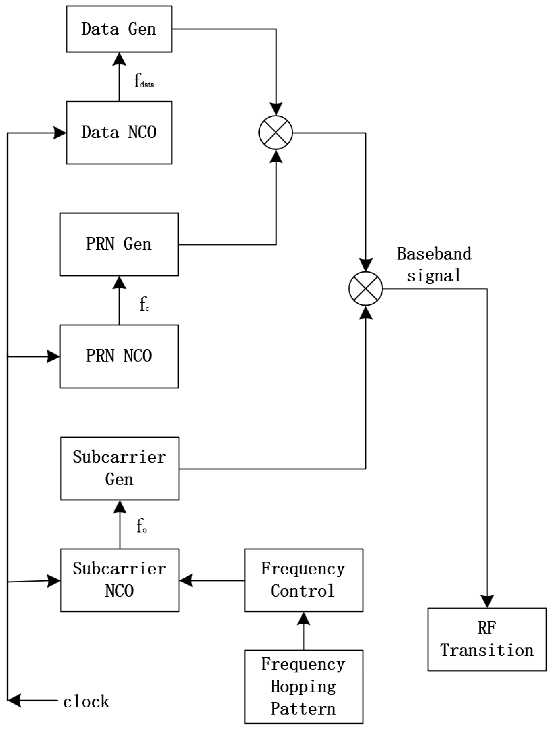
Figure 2.
Autocorrelation function and power spectral density of FH-BOC.
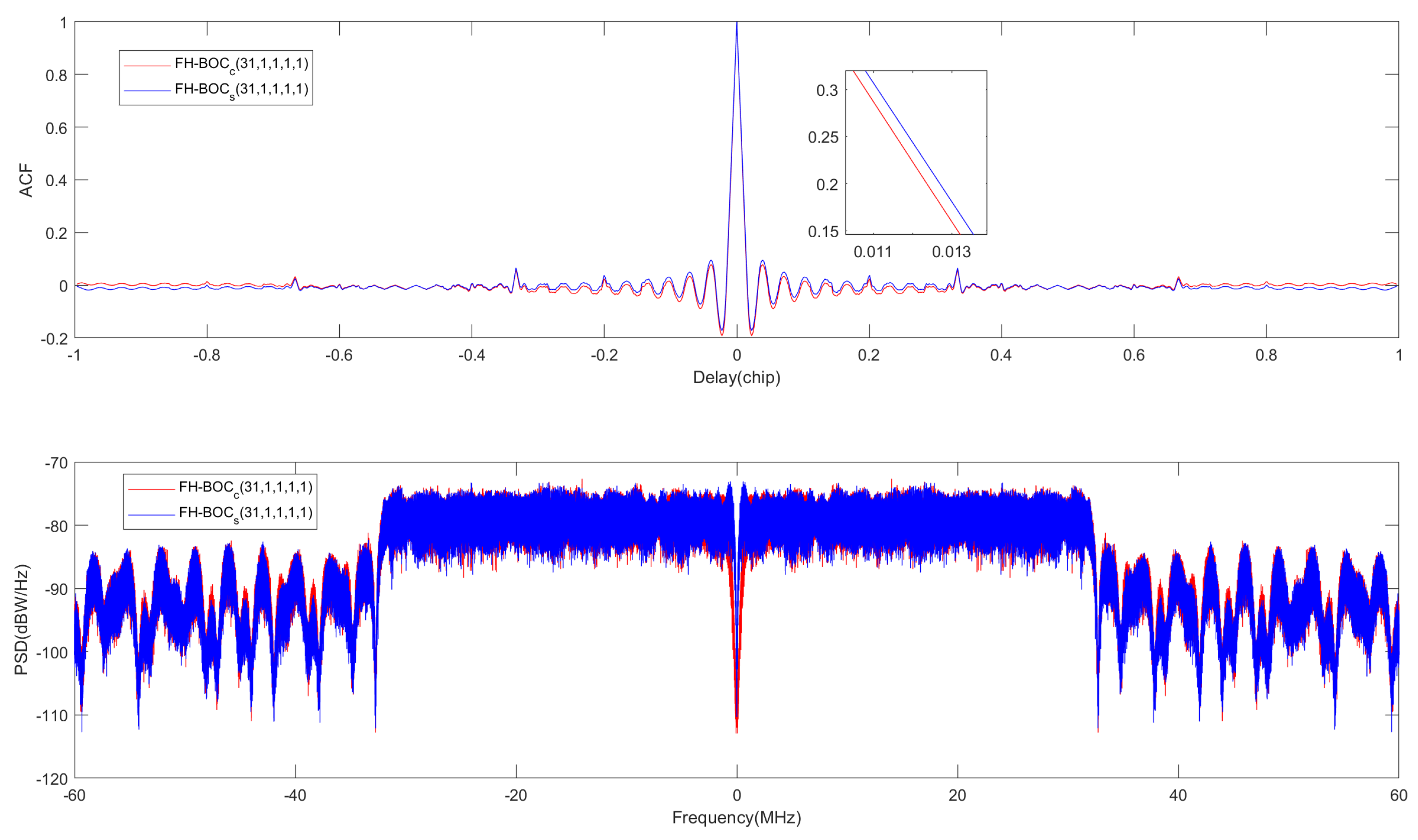
Figure 3.
Comparison of autocorrelation functions.
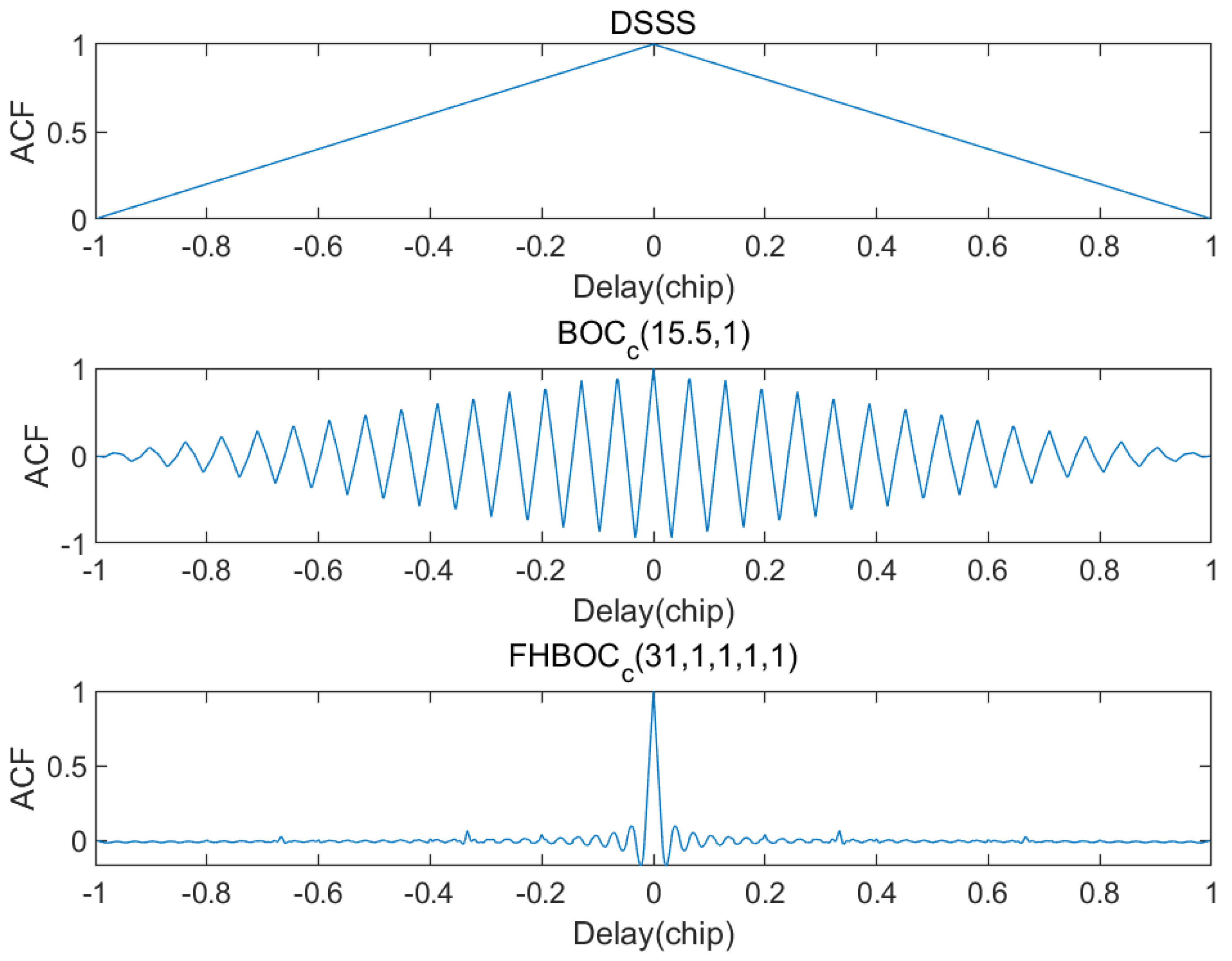
Figure 4.
Comparison of power spectral density.
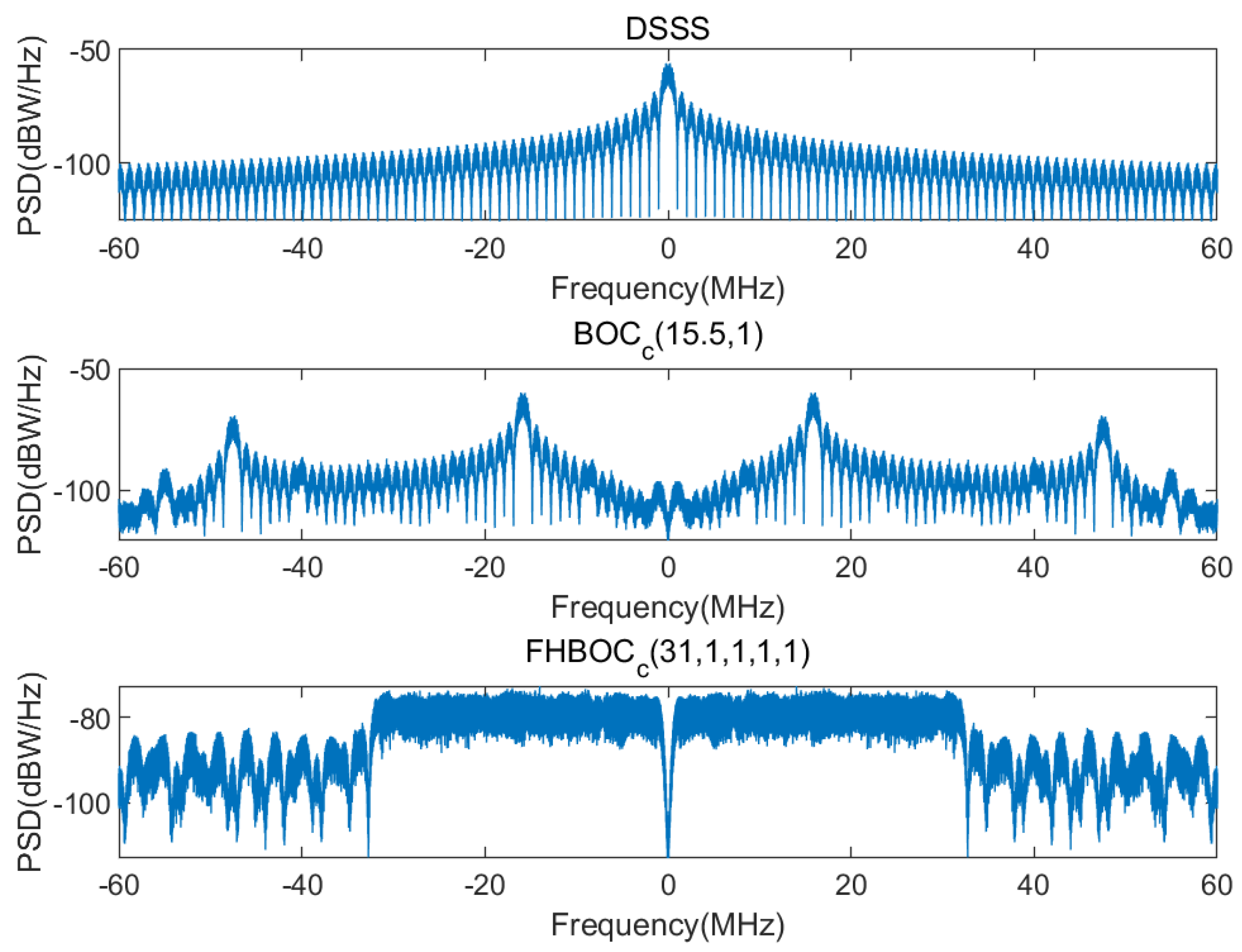
Figure 5.
JPL high-dynamic signal model.
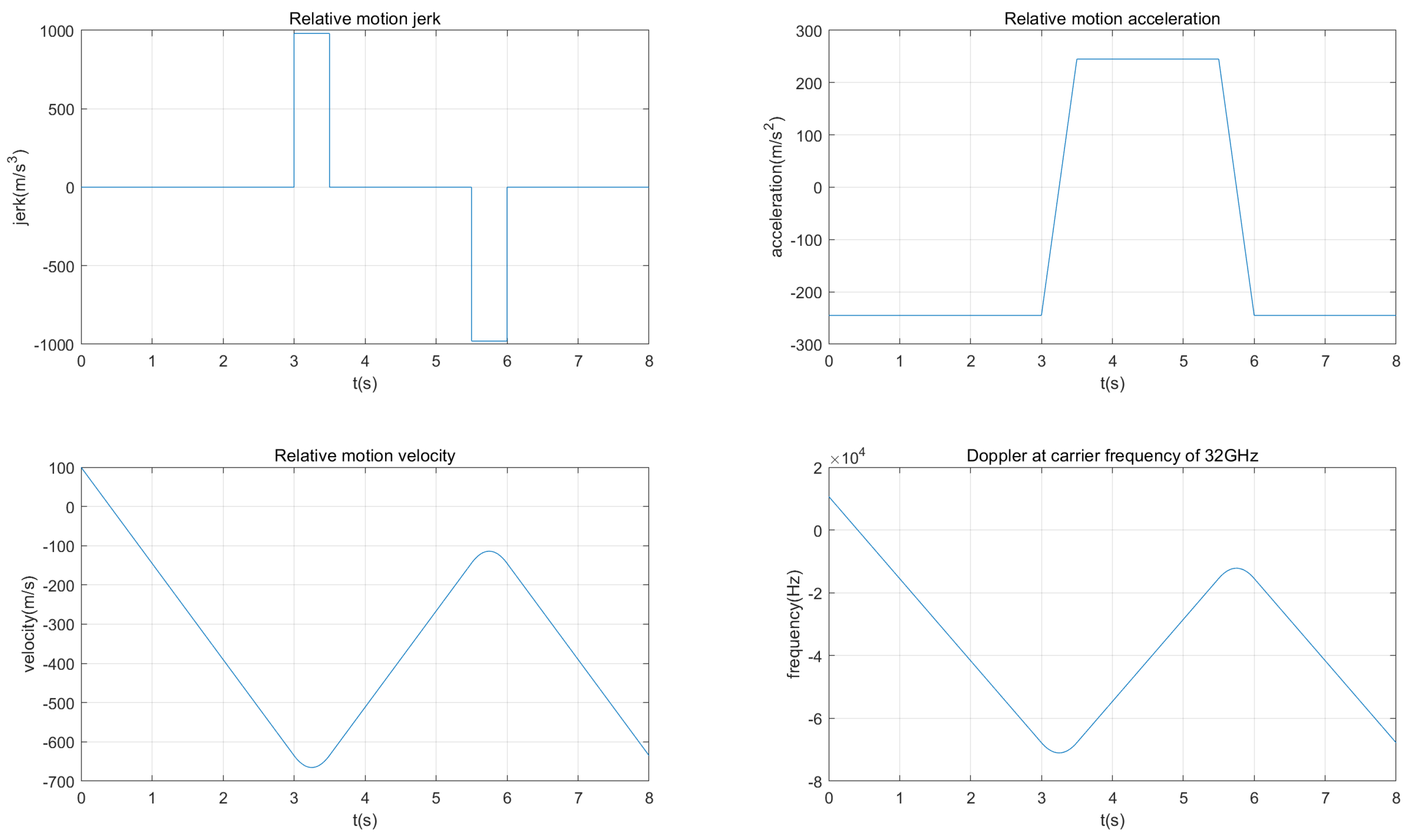
Figure 6.
Block diagram of classical carrier tracking loop.
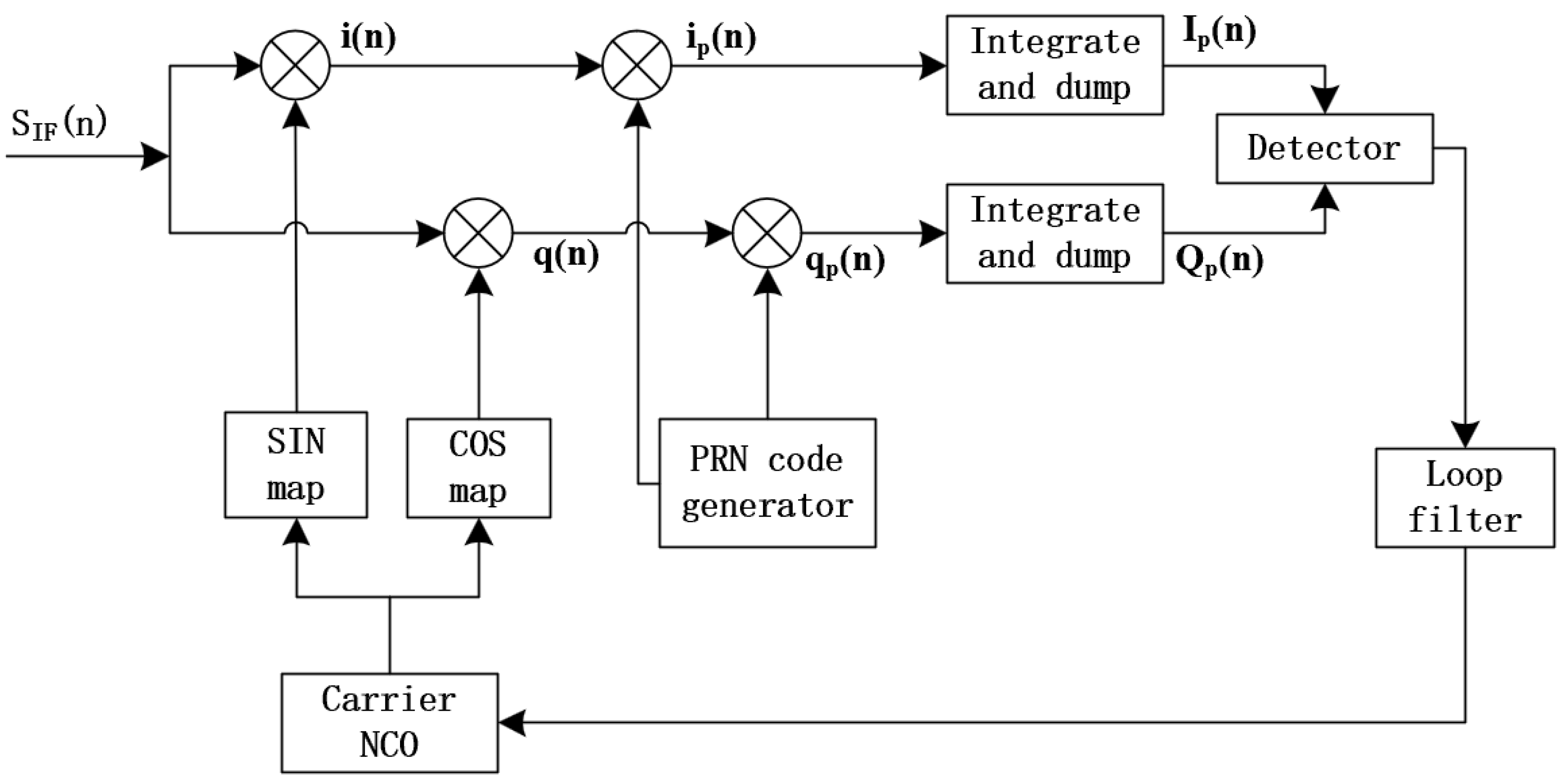
Figure 7.
Second-order FLL assisted third-order PLL.
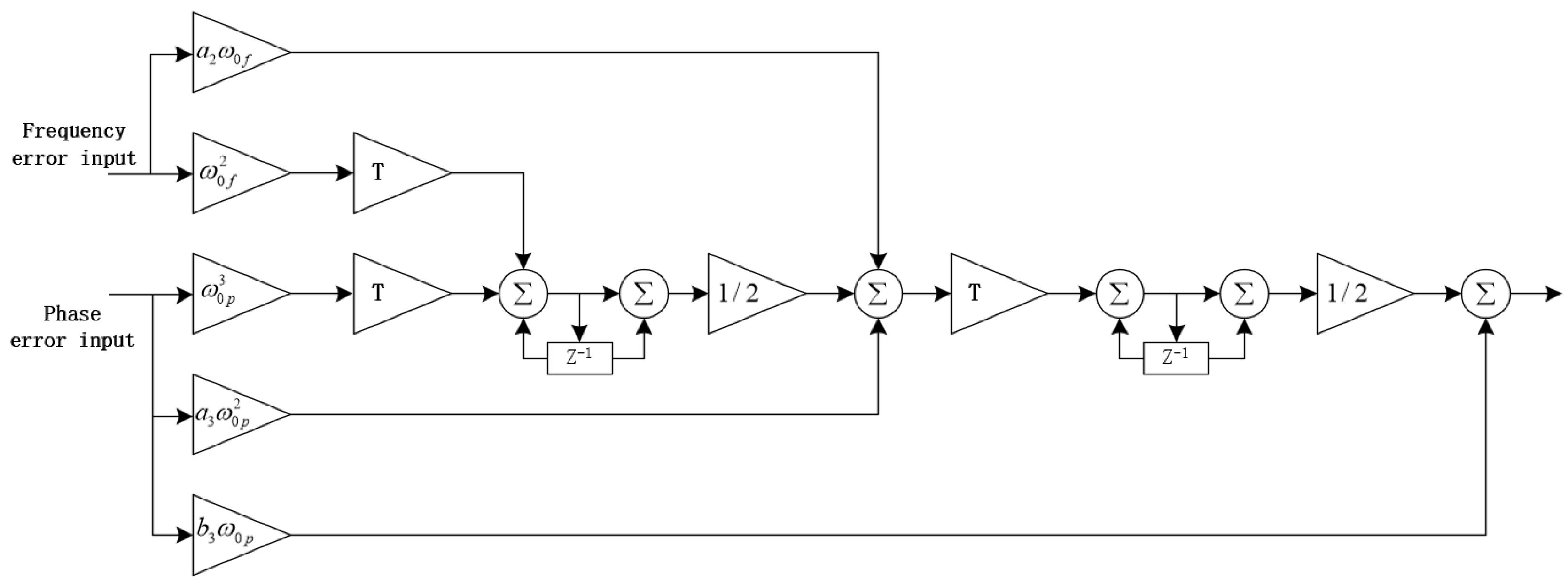
Figure 8.
Simulated results of 2nd-Order FLL Aided 3rd-Order PLL: a(1),a(2) Carrier tracking error under different CNR. b(1),b(2) Carrier doippler tracking error under different CNR. c(1),c(2) Doppler tracking status under different CNR
Figure 8.
Simulated results of 2nd-Order FLL Aided 3rd-Order PLL: a(1),a(2) Carrier tracking error under different CNR. b(1),b(2) Carrier doippler tracking error under different CNR. c(1),c(2) Doppler tracking status under different CNR
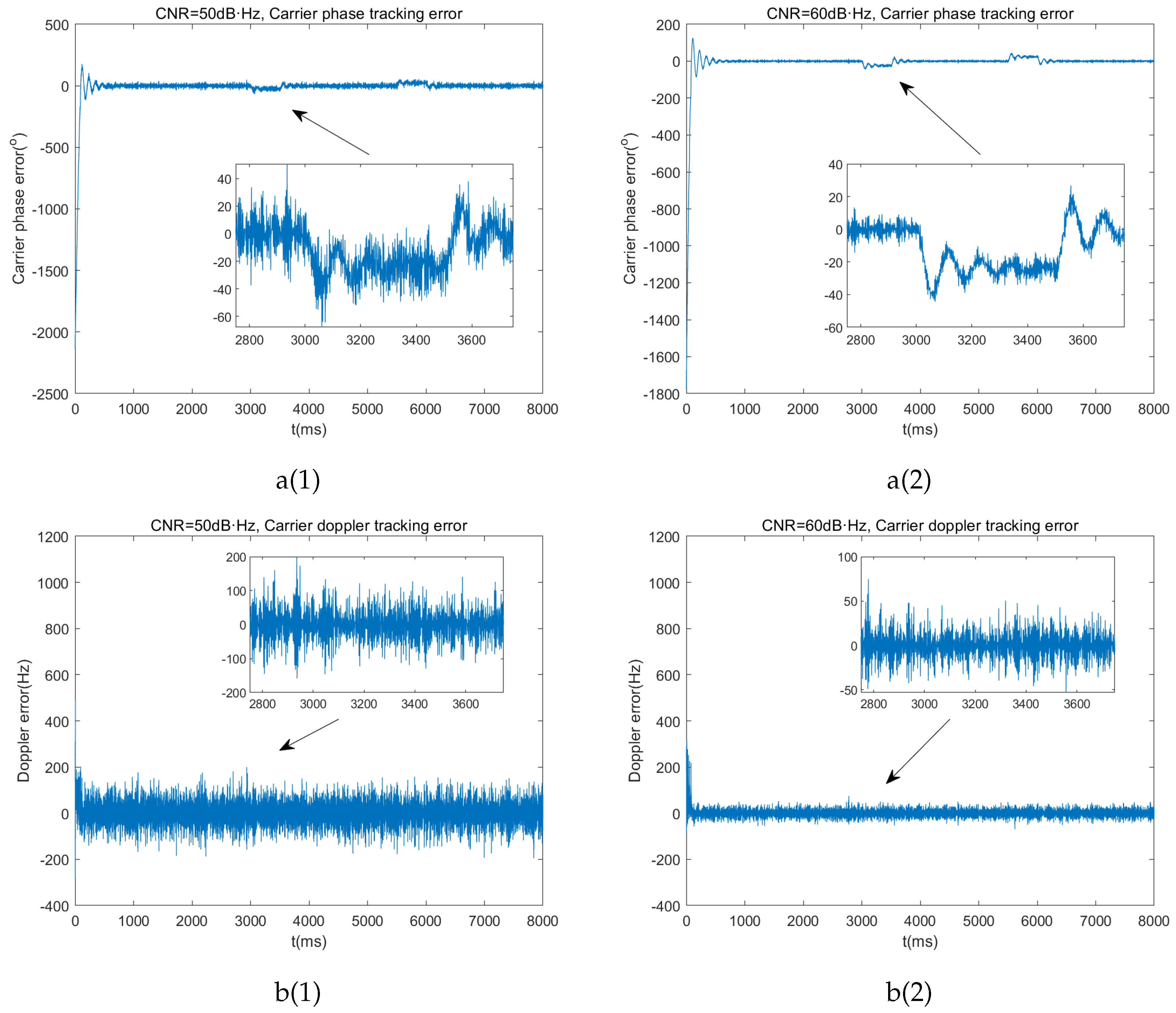
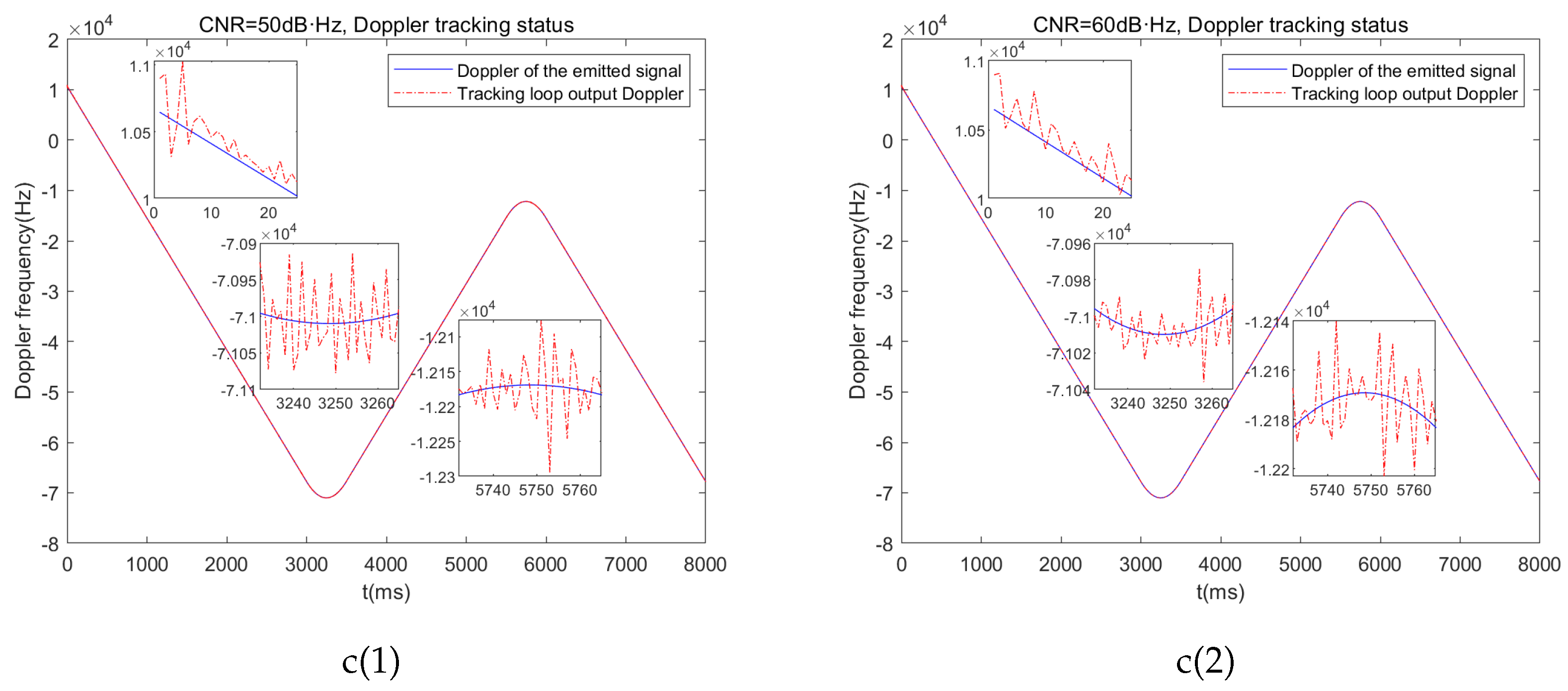
Figure 9.
Linear Kalman carrier tracking model.
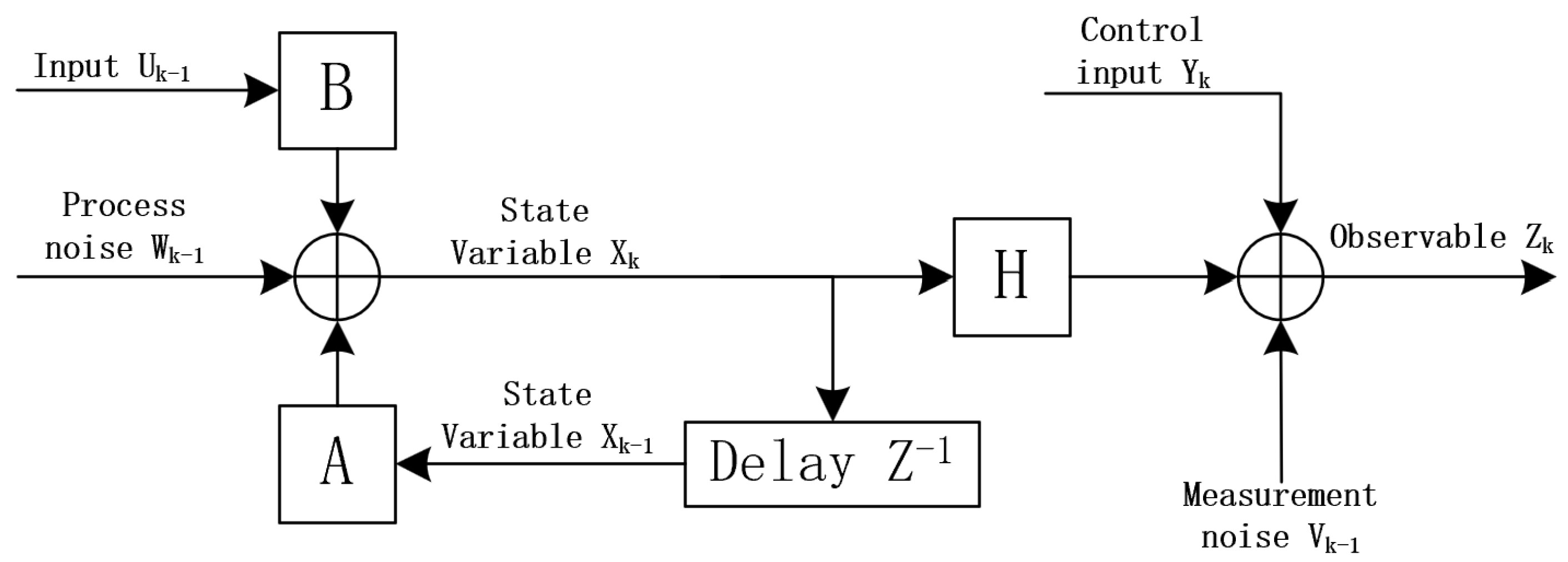
Figure 10.
Linear Kalman carrier tracking algorithm flow.
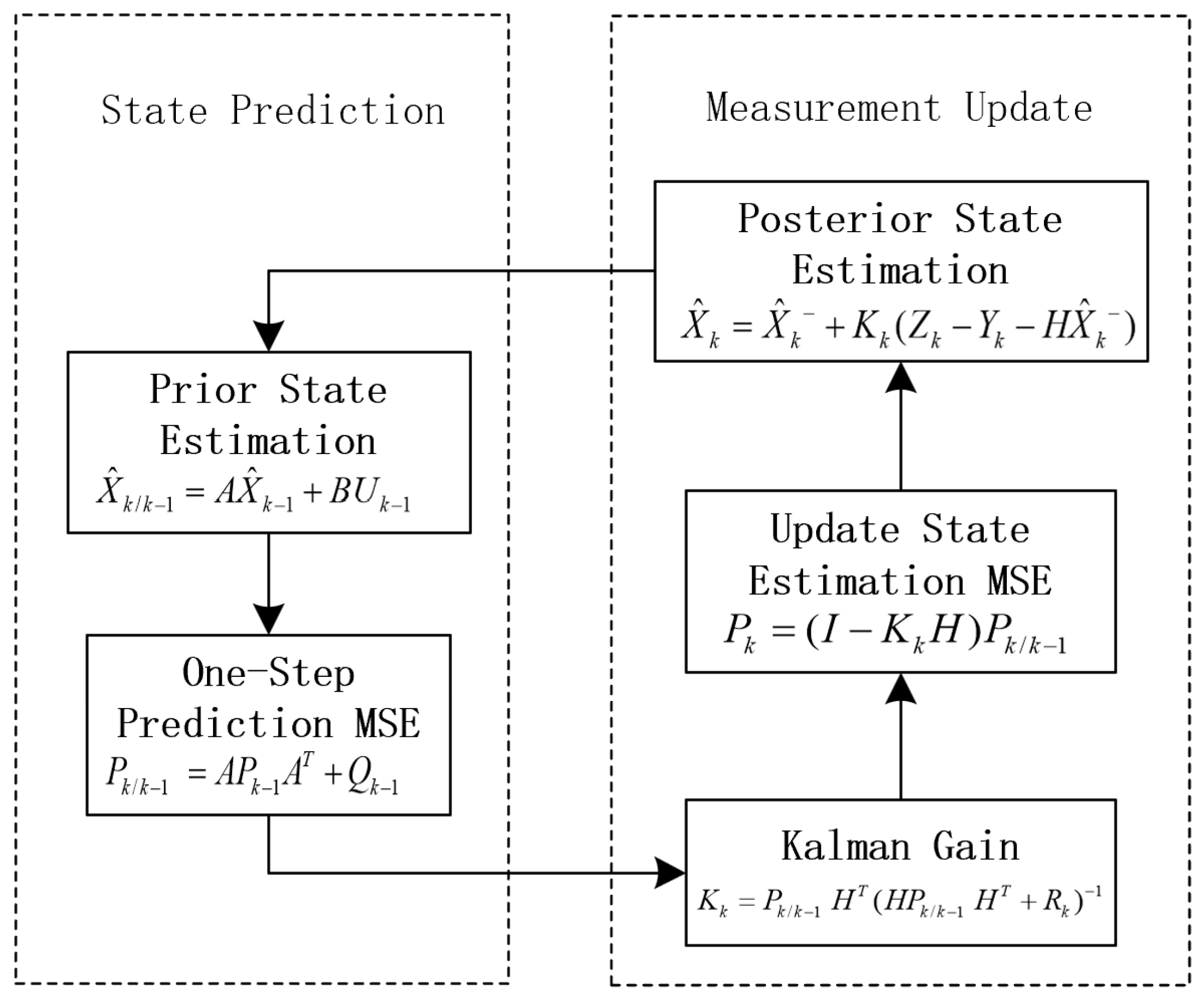
Figure 11.
Linear Kalman tracking simulation results: a(1),a(2) Carrier tracking error under different CNR. b(1),b(2) Carrier doippler tracking error under different CNR. c(1),c(2) Doppler tracking status under different CNR
Figure 11.
Linear Kalman tracking simulation results: a(1),a(2) Carrier tracking error under different CNR. b(1),b(2) Carrier doippler tracking error under different CNR. c(1),c(2) Doppler tracking status under different CNR
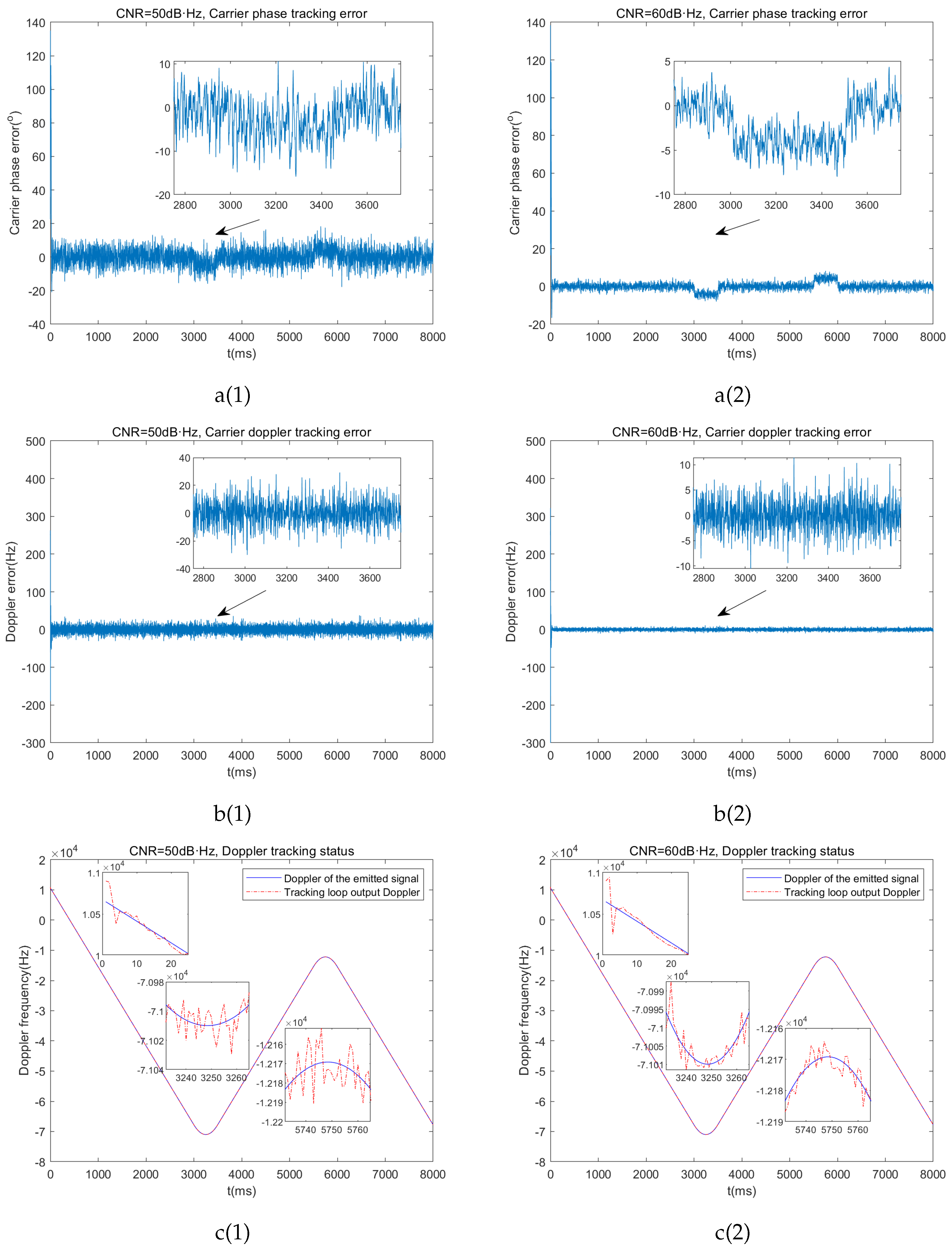
Figure 12.
Adaptive Kalman carrier tracking algorithm flowchart.
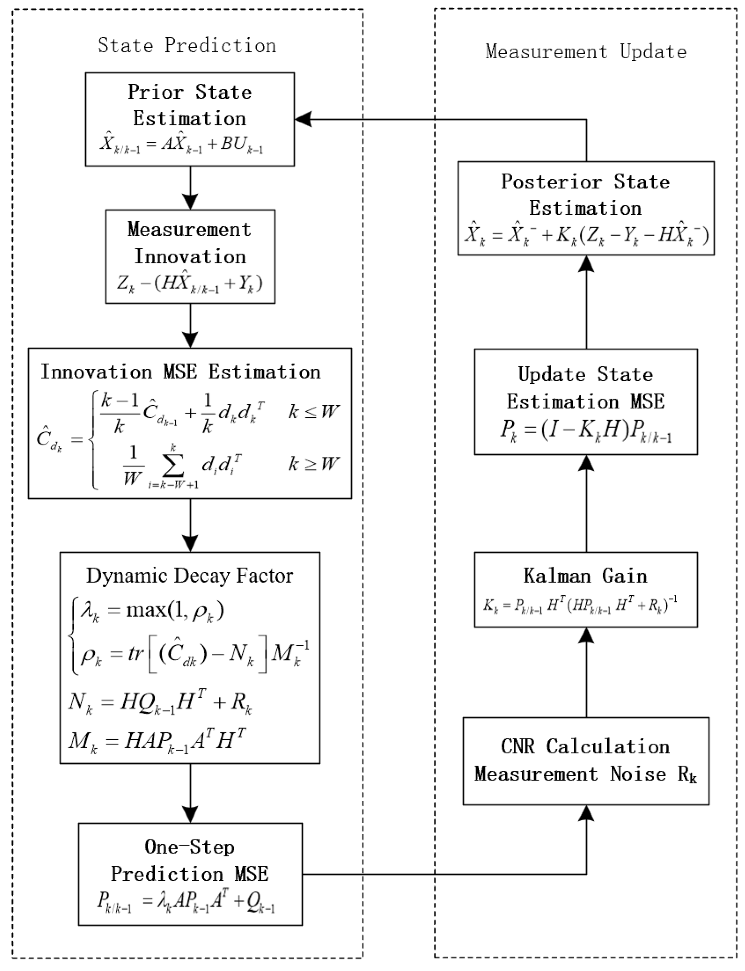
Figure 13.
Adaptive Kalman tracking simulation results: a(1),a(2) Carrier tracking error under different CNR. b(1),b(2) Carrier doippler tracking error under different CNR. c(1),c(2) Doppler tracking status under different CNR
Figure 13.
Adaptive Kalman tracking simulation results: a(1),a(2) Carrier tracking error under different CNR. b(1),b(2) Carrier doippler tracking error under different CNR. c(1),c(2) Doppler tracking status under different CNR
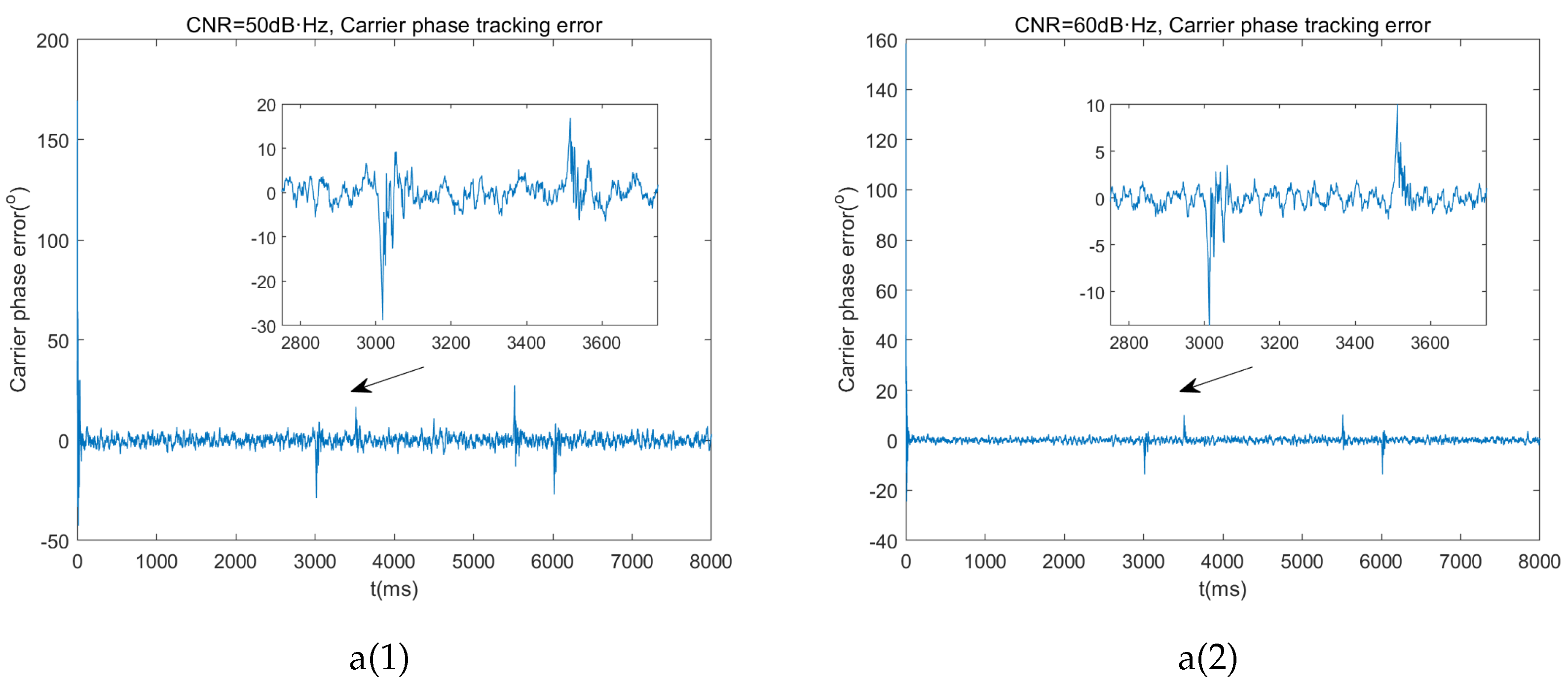
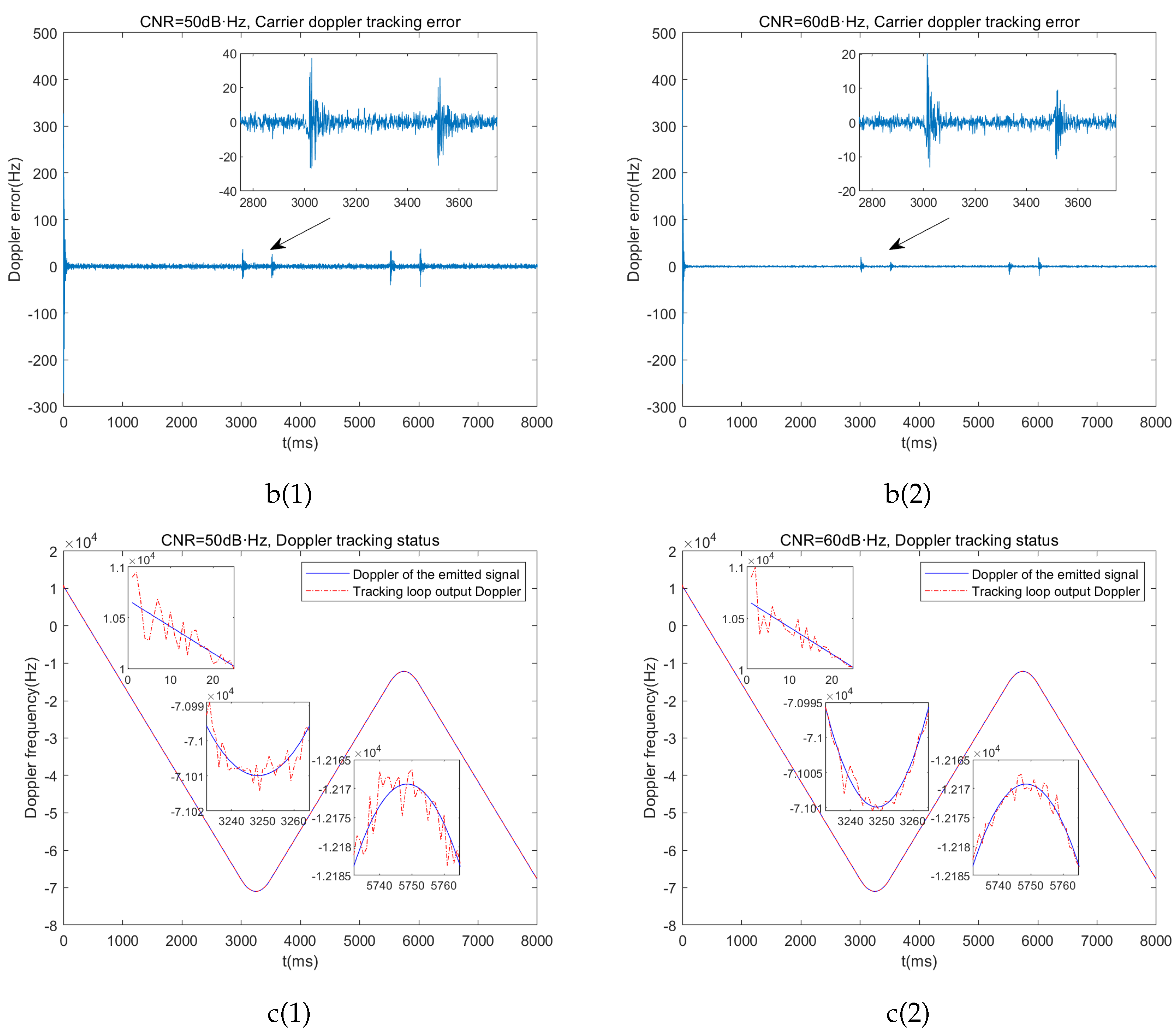
Figure 14.
High-Dynamic reception loop for FH-BOC.
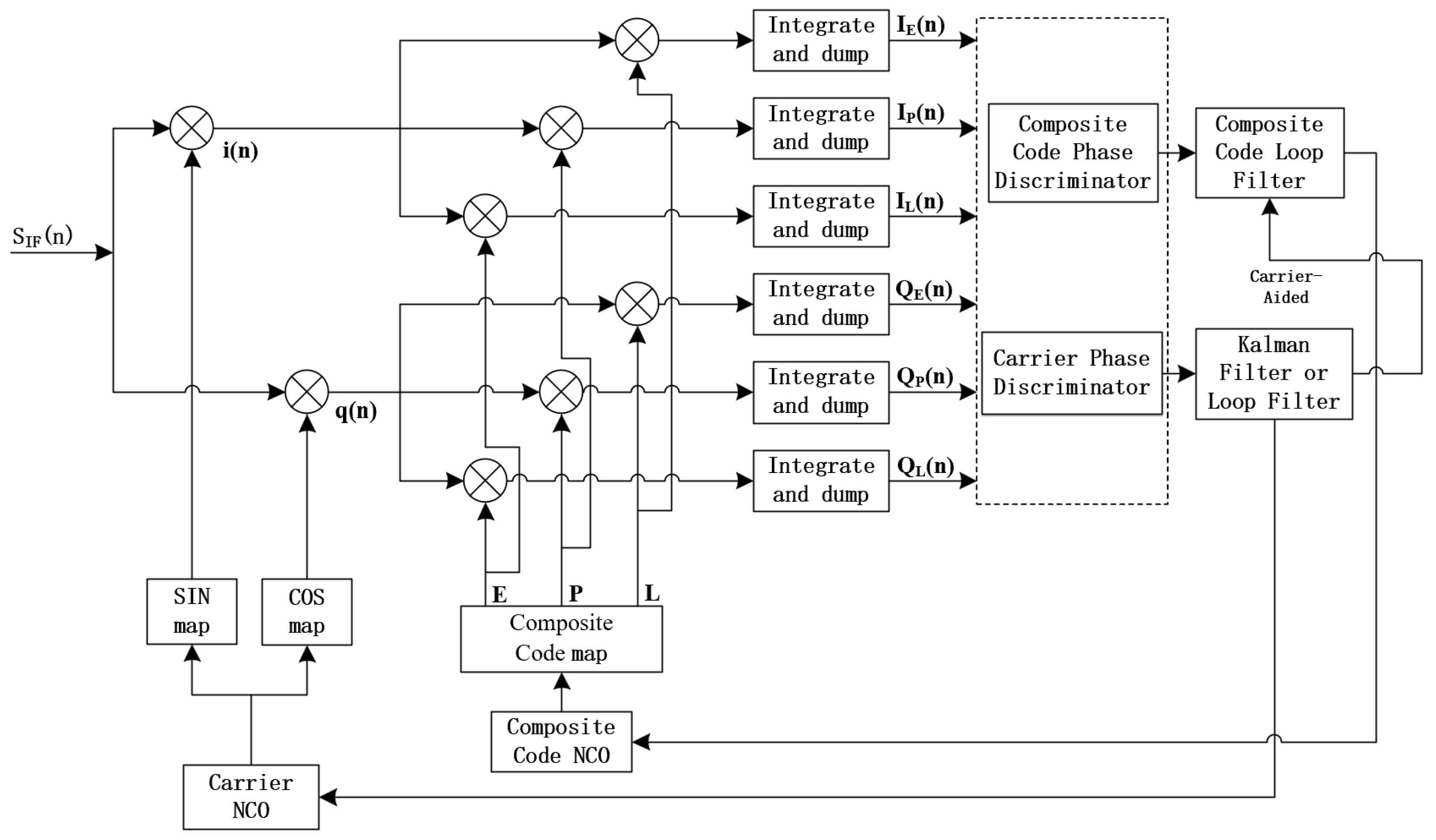
Figure 15.
The second-order DLL loop filter.
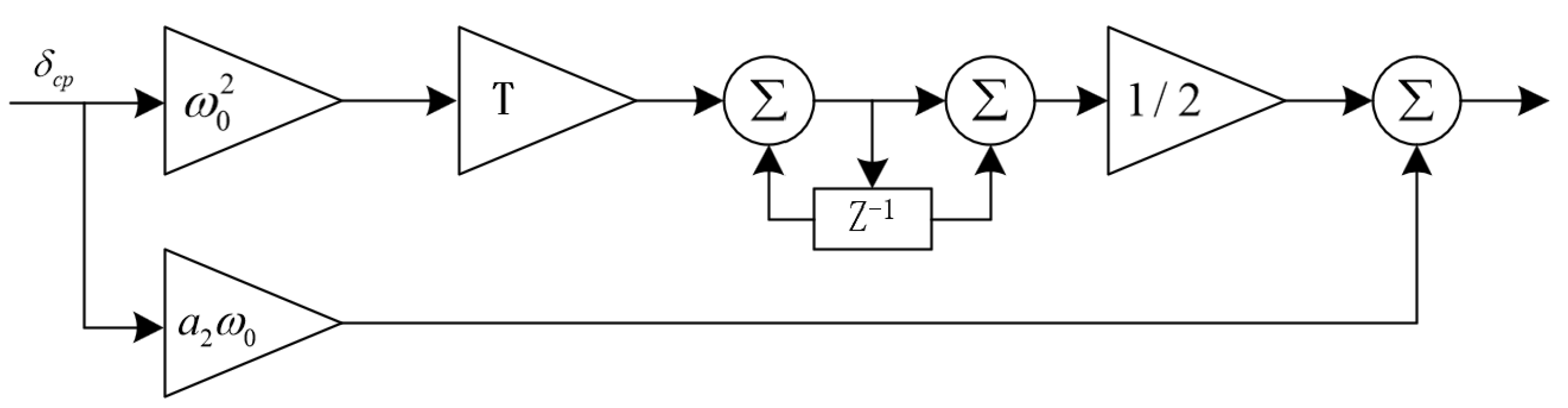
Figure 16.
Composite code offset tracking error under different CNR: (a) . (b) . (c) . (d)
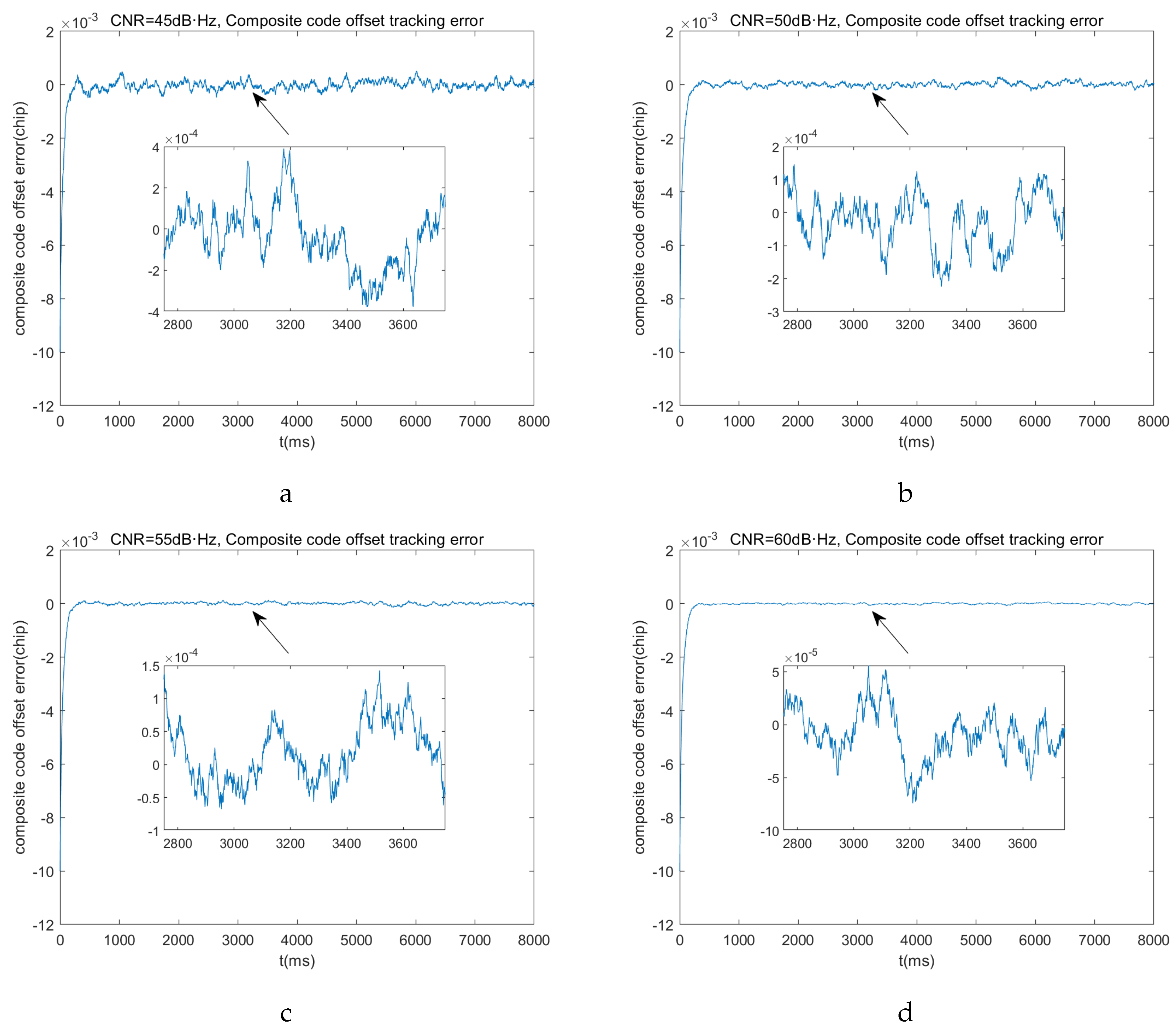
Figure 17.
Receiver loop simulation results under different CNR: (a) Carrier phase tracking error std. (b) Carrier Doppler tracking error std. (c) Composite code tracking error std.
Figure 17.
Receiver loop simulation results under different CNR: (a) Carrier phase tracking error std. (b) Carrier Doppler tracking error std. (c) Composite code tracking error std.
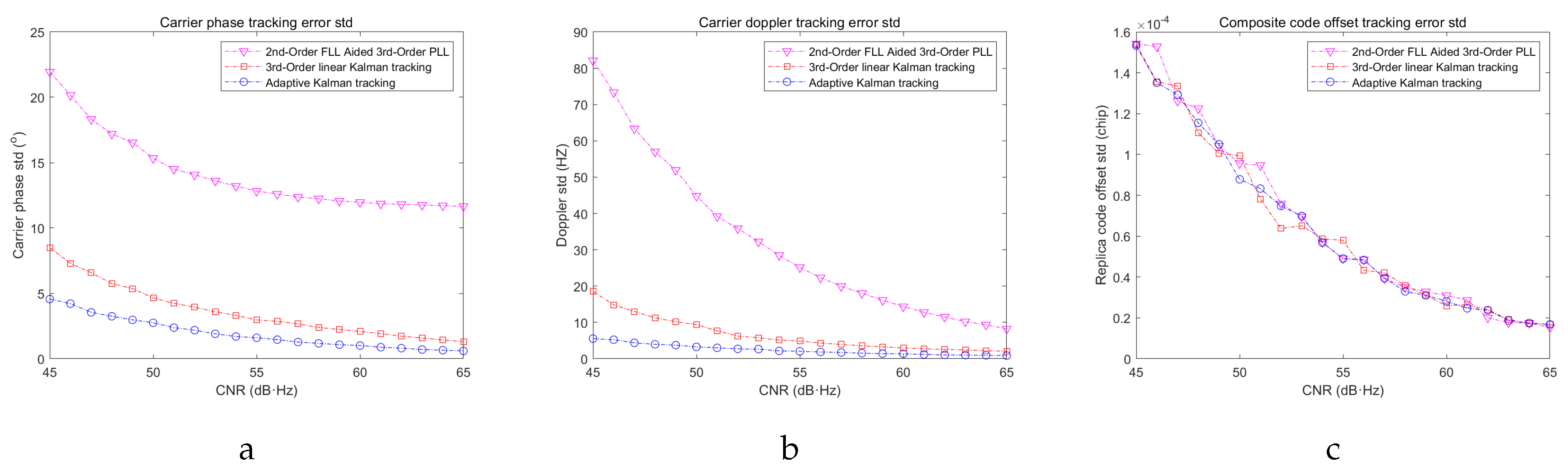

Table 1.
Loop filter parameters.
| Loop order | Noise bandwidth(Hz) | Filter values | Steady state error |
|---|---|---|---|
| 1 | |||
| 2 | |||
| 3 |
Table 2.
Loop filter parameters.
| simulation parameters | values |
|---|---|
| signal modulation scheme | |
| carrier radio frequency | 32GHz |
| Intermediate Frequency | 140MHz |
| Sampling Frequency | 400MHz |
| Doppler Motion Model | JPL high-dynamic signal model |
| Initial Residual Frequency | 250Hz |
| Coherent Integration Time | 1ms |
Table 3.
Summary of simulated results: 2nd-Order FLL Aided 3rd-Order PLL.
| Loop Tracking Accuracy | 45dB·Hz | 50dB·Hz | 55dB·Hz | 60dB·Hz |
|---|---|---|---|---|
| Carrier Phase Tracking std(°) | 21.94 | 15.34 | 12.83 | 11.97 |
| Doppler Tracking std(Hz) | 82.08 | 44.83 | 25.14 | 14.36 |
Table 4.
Summary of linear Kalman tracking simulation results.
| Loop Tracking Accuracy | 45dB·Hz | 50dB·Hz | 55dB·Hz | 60dB·Hz |
|---|---|---|---|---|
| Carrier Phase Tracking std(°) | 8.50 | 4.66 | 2.97 | 2.09 |
| Doppler Tracking std(Hz) | 18.54 | 9.39 | 4.86 | 2.97 |
Table 5.
Summary of Adaptive Kalman tracking simulation results.
| Loop Tracking Accuracy | 45dB·Hz | 50dB·Hz | 55dB·Hz | 60dB·Hz |
|---|---|---|---|---|
| Carrier Phase Tracking std(°) | 4.56 | 2.75 | 1.60 | 1.01 |
| Doppler Tracking std(Hz) | 5.55 | 3.26 | 2.05 | 1.35 |
Table 6.
Composite code tracking loop simulation parameters.
| Simulation Parameters | Values |
|---|---|
| Signal Modulation Scheme | |
| Pseudocode Employed | CA code |
| Pseudocode Length | 1023(chips) |
| Pseudocode Rate | 1.023 (MHz) |
| Doppler Motion Model | JPL high-dynamic signal model |
| Initial Residual Composite Code Phase | 0.01(chips) |
| Coherent Integration Time | 1(ms) |
Table 7.
Summary of composite code tracking loop simulation results.
| Loop Tracking Accuracy | 45dB·Hz | 50dB·Hz | 55dB·Hz | 60dB·Hz |
|---|---|---|---|---|
| Composite Code Phase Tracking std(1x10⁻⁴chip) | 1.5321 | 0.8778 | 0.4919 | 0.2801 |
Disclaimer/Publisher’s Note: The statements, opinions and data contained in all publications are solely those of the individual author(s) and contributor(s) and not of MDPI and/or the editor(s). MDPI and/or the editor(s) disclaim responsibility for any injury to people or property resulting from any ideas, methods, instructions or products referred to in the content. |
© 2024 by the authors. Licensee MDPI, Basel, Switzerland. This article is an open access article distributed under the terms and conditions of the Creative Commons Attribution (CC BY) license (http://creativecommons.org/licenses/by/4.0/).
Copyright: This open access article is published under a Creative Commons CC BY 4.0 license, which permit the free download, distribution, and reuse, provided that the author and preprint are cited in any reuse.


