
Submitted:
13 August 2024
Posted:
13 August 2024
You are already at the latest version
Abstract
The research aims to present an innovative methodology to execute the Heritage conservation processes in a collaborative and interdisciplinary BIM project, with an effective management of the deterioration suffered over time, emphasizing the structures and coatings. The research begins with the architectural survey using scanning techniques (TLS) and terrestrial photogrammetry (SfM) and taking as a study the Duomo of Molfetta (Italy), a unique Romanesque architecture of Puglia (Italy). The methodological process is mainly aided by the precise semantic segmentation of global point clouds, a semi-automatic process assisted by classification algorithms implemented in the post-processing software, and which has allowed the classification of the unstructured information provided by the remote sensing equipment when identifying the architectural-structural systems of a building with high historical values. Subsequently, it has been possible to develop an efficient Scan-to-HBIM workflow, where the Heritage-BIM (HBIM) project has fulfilled the function of a database by incorporating and organizing all the information (graphic and non-graphic) to optimize the tasks of auscultation, identification, classification, quantification and, in turn, facilitating the parametric modeling of unique structures and architectural elements. The results have shown great effectiveness in the processes of characterization of architectural and artistic heritage, focusing on the deformations and deterioration of the masonry in columns, and making multidisciplinary conservation work in an HBIM project more flexible. But there are still some difficulties for the automatic interpretation of 3D point cloud data, related to specific systems of the historical architecture. In conclusion, human action and interpretation continues to be a fundamental pillar to achieve precise results in a heritage environment.
Keywords:
Architectural heritage
; Conservation of the Duomo di Molfetta
; Deterioration of masonry
; HBIM
; Semantic segmentation
; Scan to BIM
1. Introduction
Every form of sculptural and graphic expression, whether artistic or architectural, carries with it the principles of semiotics and semantics. Semiotics in architecture refers to the analysis of the symbolic and significant aspects of architecture. The discipline of architectural surveying, accompanied by a scientific and technical methodology, guides the scientific knowledge of the works, as well as their form and context [1]. The study of heritage refers to the past in its context of the inheritance received, and technology represents the contribution to a future to come. In this framework, 3D modeling aims to contain and reflect the uniqueness of geometry, considering the structural deformations and construction properties they acquire throughout their life cycle.
The geometry of Cultural Heritage (CH) is captured by technology procedures that have to do with engineering and geomatics, which have become a common practice, such as digital terrestrial photogrammetry (TDP), photogrammetry with unmanned aerial vehicles (UAVs), together with the photogrammetric process by Structure from Motion (SfM), and technology by Terrestral Laser Scanning (TLS) for 3D digital reconstruction [2]. The current research agenda recommends the need for an interpretation of the set of 3D points, with the aim of identifying and quantifying patterns of elements from the decomposition of the elements, looking for functionality, semantics and topology [3]. To help conserve and document CH, researchers are also implementing multiple prospecting techniques at once. For example, Costantino et al., 2023 [4] included the "Digital Single Lens Reflex" (DLSR) camera and TLS for indoor and outdoor studios, merging active and passive sensors. Rocha et al., 2020 [5] used TLS and TDP to achieve detailed and accurate representations; others perform comprehensive surveys of DSLRs, UAVs, and TLS cameras [6]; Alessandri et al., 2019 [7] performed rapid photogrammetric surveys using a Nikon D800E DSLR; and Di Stefano et al., 2019 [8] applied TDP and spherical photogrammetry (SP) for data representation and enrichment.
Moreover, artificial intelligence (AI) is playing an important role in the preservation and study of the PC with a view to automating processes; it is used in the conservation and restoration of architectural heritage in various ways, such as virtual reconstruction of historic buildings, image scanning and recognition, remote sensing, and degradation prediction for preventive conservation. In the field of remote sensing, major advances in image matching algorithms are changing the landscape of 3D architectural and archaeological reconstruction. In addition, with the arrival of new geomatic technology equipment, such as the personal mobile laser scanner (PLS), data capture in the measurements of architectural spaces is simplified [9]. And a new development in the integration and combination of TLS equipment with Light Detection and Ranging (LDR), LiDAR scanners on board drones, are one of the most cost-effective systems that can provide spatial data. Among the most prominent, the DJI Matrice 300 RTK Zenmuse L1 UAV, used in forestry studies [10], and the Leica BLK2GO that captures moving images [11]. Each of the aforementioned techniques is associated with the registration space that is intended to be obtained. But once the record has been obtained and the processing of that data is obtained, a set of points is obtained that is not classified. Therefore, the great challenge for the scientific community is to have procedures for classifying complex elements in architecture and archaeology. This classification is valid for processing data in current BIM methodologies that allow interdisciplinary collaboration and the combination of compliance verification and analysis tools. In this sense, segmentation is a process of point cloud classification for the identification of homogeneous areas or entities that have similar characteristics, let's call them point cloud attributes. But currently one of the challenges is to manage and process all that data so that it has basic functionality, not only in 3D digital models, but also in the applicability of the Historic Building Information Model (HBIM) environment [9].
2. Literature Review
2.1. Remote Sensing in Heritage
The scientific community is very intensively involved in the efficient management of the data provided by remote sensing, photogrammetric and scanning systems, since the 3D information provided through large numbers of points (PCs) is essential to document and analyze the state of conservation of architectural heritage.
PCs allow an agile and detailed assessment of the structural condition of the historic building, reducing laborious "on-site" inspections [12], and provide precise information on the texture and geometry of the surfaces, scanned or photographed, which can then be analyzed to identify damage to the structures [13].
Laser scanning and photogrammetry are appropriate to cover large heritage sectors, reducing the time of auscultation and taking measurements, which make them very efficient technologies in places that are difficult to access [14]. The post-processed information provided (PCs) facilitates the documentation and analysis of sites located in very heterogeneous environmental conditions and in places inaccessible by more traditional methods, which helps in inspection and monitoring tasks [15]. Both the acquisition and analysis of collected data prove to be faster and less expensive compared to traditional inspection and measurement methods [16]. Another potential is the capture of minimal details and the exact identification of deteriorated surfaces, such as cracks, fractures and loss of material, thus contributing to an adequate analysis of the structural condition [17] and the state of the coatings associated with the heritage elements.
2.2. Detection of Deterioration
Automating the process of detection and semantic segmentation of deteriorated surfaces of heritage buildings based on the study and management of PCs, acquired through photogrammetric and TLS techniques, and their implementation in the modeling of heritage building information (HBIM), is nowadays a priority for a large number of researchers. The aim is to improve manual and time-consuming procedures, replacing them with efficient and precise automatic processes that support architectural heritage conservation efforts. Unsupervised machine learning and deep learning methods, based on dynamic convolutional neural networks, usually aid the most autonomous segmentation and classification. The process involves the accurate recognition of architectural elements and accelerate the modeling of historic buildings for the development of the HBIM project [18]. Machine learning methods and clustering techniques to automatically segment PCs can also help detect alterations in historical surfaces, such as color variations and biological colonization, based on color information from PCs [19]. The main objective of these methods is to automatically detect objects and data using specific algorithms to evaluate and monitor the condition of buildings and, thus, identify deteriorated surfaces. In parallel, these advanced techniques contribute to an accurate and rapid assessment of structural degradations, facilitating continuous monitoring and the development of effective conservation strategies [20]. Another benefit of PC segmentation is the improved performance of 3D data management platforms by reducing calculation time and increasing model accuracy [21]. In the specialized literature, various automatic systems have been developed for the detection of cracks and degradations. Muñoz-Pandiella [22] uses the Gaussian Filter and the Random Sample Consensus (RANSAC) algorithm for the detection of the initial shape of the cracks. Peng y Nam [23] have created a system that identifies cracks by using Gaussian Filter, Intensity Gradient, and pattern detection. While Sánchez & Quirós [24] propose a semi-automatic detection method based on an image approach to identify degradations in facades.
Classification methods that are not aided by machine learning are also very effective [25] and therefore do not rely on extensive training datasets. They are mainly based on image processing techniques and detected geometric analysis. These methods have the great advantage of being flexible and efficient in terms of time, cost and implementation, reducing the risk of overfitting [26]. For all these reasons, bearing in mind that the final objective of the research is the management of data intrinsic to the semantic and parametric elements of an HBIM model, the proposed methodological process is aided by a semi-automatic semantic segmentation, although more accessible and efficient. The operator's supervision will always ensure the accurate detection of deterioration in historic buildings.
2.3. Data Classification
Most segmentation studies use software external to the software used for processing. In these cases, they apply the RANSAC-based plane adjustment algorithm to add an additional layer of abstraction [3]. RANSAC is an iterative algorithm used to estimate the parameters of a mathematical model from a dataset containing a significant proportion of outliers. It was introduced by Fischler and Bolles in 1981 [27] and it has become a standard technique in computer vision, image processing, and point cloud. It is based on the idea of repeatedly selecting a random subset of the input data, fitting a model to this subset, and then evaluating how the model fits the entire dataset. RANSAC's key strength is its ability to cope with a high level of outliers in input data. Unlike traditional tuning methods that can be affected by outliers, this algorithm ignores outliers and focuses on most of the data that fits the model well [28]. Examples are the research that develops a classification based on model adjustments through the determination of geometric primitives, using the RANSAC algorithm and the Hough transform as classification processes. Dong et al., 2018 [29] conducted a segmentation classification based on four essential points. Methods based on the growth of the region, which extract 3D planes by progressively merging adjacent points or voxels with similar characteristics [30] among others. Methods based on model fitting, which are most commonly used for plane segmentation (RANSAC) and Hough transform. These algorithms have successfully demonstrated 2D and 3D shapes. Later there are methods based on function clustering, which characterize point clouds in primitives based on certain pre-calculated surface properties [31]. To this large set of studies on segmentation, the usefulness and functionality of classification procedures must be proposed. Many of the studies are dedicated to the classification of urban regions, others to interior spaces, selection of objects, elimination of noise in the point cloud, classification of urban furniture, or also the creation of digital twins in the field of CH and morphological semantic segmentation [32].
Some research offers more advanced segmentations in architectural heritage as they implement machine learning in parametric BIM modeling [33]. The process consists of the transition, still semi-automated, from unstructured TLS data to the semantically rich representation of buildings and historical H-BIM assets, applied mainly to recurrent architectural typologies that are supported by construction rules and/or building proportions, as is the case of a Renaissance loggia. The objective is to achieve an effective, precise and productive interdisciplinary process that can be shared by architects, engineers, conservators and restorers to update, retrieve and archive the available heritage information based on semantically enriched parametric models. For this reason, for the HBIM project of the Duomo di Molfetta, intelligent process automation is also sought, using, in this case, the classification algorithms implemented in various software tools [34] with the aim of simplifying the frequent tasks of management, point cloud classification and reverse engineering, thus reducing the times in the development of architectural projects, engineering, construction and conservation (AECO).
2.4. The Scan-to-HBIM Process
If the above is analyzed, it is essential to combine the various techniques to achieve an efficient methodological process that takes advantage of each prospecting method to achieve the best conservation and documentation requirements. This is where the Building Information Modeling (BIM) methodology provides a fundamental help to integrate the various conservation and documentation data (graphic and non-graphic) into a comprehensive historical construction model. The identification of geometric characterization in a Heritage BIM (HBIM) project is crucial for operators who are morphologically modeling architectural elements. The process initiated in Massive Data Capture Systems (MDCS) that involves the construction of 3D models with parametric objects, called Scan-to-BIM, presents great challenges due to the complexity of the historical architecture, always seeking to solve the errors of the BIM model according to a scanned work (Tzedaki and Tamara, 2013) [35]. This is posed as the challenge of the construction of the ideal model and, on the other hand, of the deformations that arise on site, admissible by the technical teams of execution of the project. In architectural heritage, this difference between the ideal model and the real model becomes more and more pronounced as time goes by in the life cycle of old buildings, due to the deterioration of the elements. Therefore, the great challenge and scientific discussion focuses on the automatic position of capturing the structural deformations that can occur in an HBIM project. There are several scientific reviews of the combination of remote capture of information, such as 3D laser scanning, with BIM applications [36,37], where the dilemma of finding operators who can solve complex geometries is raised. The problem also arises that the manual process of constructing the geometry of a historic building from the point cloud is a process that requires a considerable amount of time, since it is necessary to structure the point cloud in parts and to make an efficient classification of the data [38] and eliminate those that are unnecessary, usually according to the criteria of the rehabilitator-operator. Another aspect that should be highlighted is the amount of information that is managed, since the point cloud has an important weight where BIM platforms must overcome and manage efficiently.
For all these reasons, the challenge of this research is to make a classification and semantic segmentation of the point cloud by architectural/structural typologies, facilitating the modeling and management of the HBIM project in the conservation process; incorporating, in addition, the deformations and deterioration that the structural elements of the Duomo di Molfetta have suffered, both in their real geometric facet and in their analytical data. These peculiarities of a historic building, although they have been classified and analysed under the environment of a specialised engineering software (Cyclone 3DR Leica), are perfectly linked to the HBIM project (Archicad Graphisoft®).
3. Methodological Process
All this study involves a deep knowledge of the historical architecture by applying a semantic segmentation of the point cloud and its processing in a common data environment managed from the HBIM project. The methodology is supported by a semi-automatic process assisted by algorithms that allows classifying and segmenting the unstructured information provided by the TLS scanner to support the HBIM project. The Duomo di San Corrado, Molfetta (Italy), an example of Apulian Romanesque architecture and an emblematic representation of Heritage, has been chosen for the study. The building was scanned in its entirety inside and main façade, while photogrammetry covered the survey of the other facades.
The paper presents the results of a semantic segmentation method based on classification algorithms that are implemented in point cloud processing software, such as Cyclone 3DR from Leica Geosystems. A direct workflow is created with the BIM platform so that the fractions of points, already identified, are introduced into the HBIM project for classification, according to architectural typologies and construction systems. This fragmentation makes BIM parametric modeling more flexible. To cover the conservation phases, specific properties are created for the identification and analysis of the deterioration detected in the building structures. Subsequently, a marking and labelling of the deterioration is carried out, which is consummated in the risk assessment.
The methodological process reinforces the interoperability of the HBIM project data with conservation and restoration specialists at all times. A comparative analysis of some defects of the Duomo columns is carried out, comparing the TLS information with the theoretical parametric object. Finally, the HBIM project incorporates the deterioration located in the structures, associated with the real geometry of the parametric elements of the model, whether in the form of groups of points segmented by categories or as 3D mesh surfaces, all of them identified and classified. They have also been enriched with the technical reports obtained from the study of pathologies (Figure 1).
3.1. Case Study
For the experimental study, a survey of the Duomo of Molfetta (Italy) is carried out using terrestrial laser scanning techniques. Built between 1150 and the end of the 13th century, the building is a unique example of Romanesque-Pugliese architecture (Figure 2. (a). With respect to the spatial configuration of its construction, it has an asymmetrical basilica floor plan, divided into three naves by cruciform columns. The central nave has three domes, supported on a hexagonal drum (Figure 2. (b). Of the large volumes, the roofs that cover the aforementioned vaults and the two bell towers that flank the main façade stand out.
3.2. Architectural Survey Process
The interior of the Duomo di Molfetta is scanned by a CAM2 FARO Focus 3D 120 Ground Laser (TLS) scanner, with an accuracy of ± 2 mm and a range of 0.6 m at 120 meters, a registration speed of 976,000 points/second and a field of view from the vertical and horizontal plane of 305º to 260º. The TLS survey was carried out by researchers from the Laboratory of Architectural and Urban Modelling (MAULab), Politecnico di Bari (Italy), and 56 positions were necessary for the complete scan of the interior of the Duomo, which includes the three main naves, the perimeter chapels, the presbytery and the east-facing altar. The west-facing façade was the only part of the exterior scanned, which has served to provide metric data and scale the photogrammetry applied to the exterior of the building, adequately coupling the point clouds of both processes and avoiding decompensation errors. Exterior capture is carried out by Digital Single Lens Reflex (DLSR) short-range photogrammetry. An 18-megapixel Canon E650D SLR camera is used, with a CMOS (APS-C 14 × 22.3 mm 2) and optical image stabilizer. The photogrammetric process by Structure from Motion (SfM) is executed in the Agisoft Metashape software (Figure 3.(a), allowing to obtain portions of walls in textured 3D meshes that will then be incorporated into the HBIM project (Figure 3.(c)). The meshes are previously optimized, reducing the number of triangles in Cyclone 3DR (Figure 3.(b)).
For the global post-processing of the data, Leica Geosystems' Cyclone Register 360 is used to register the TLS scans and, subsequently, the Cyclone 3DR software for the coupling and management of the different point clouds (TLS & SfM), as well as for the semi-automatic semantic segmentation processes using analysis and classification algorithms. The workflow developed in Cyclone 3DR has been very effective for a limitation and effective visualization of the large point cloud, using 3D section boxes to focus on areas with complex geometries or difficult to access. This procedure facilitates the correct delimitation of the architectural geometries and the subsequent precise segmentation of decorative moldings of free forms, cornices and architectural finials, with certain complexities at the intersection of the structural systems: meeting of walls with pilasters, arches of discharges under the barrel vaults and intersections of the hemispherical domes with the central vault.
The HBIM project is based on Graphisoft®'s ArchiCAD platform, where all the structured information from TLS and SfM processing is managed. Initially, all portions of the original file (supplied in rcp format) are previously managed from Recap Autodesk® to proceed with its appropriate orientation, georeferencing and sectorization. The global TLS point cloud is subdivided into four fractions before being incorporated into the HBIM project, and it is not necessary to reduce the number of points from post-processing (limit: 250 million points), before being converted into parametric objects. Next, all the datasets (e57 format) are exported to the ArchiCAD BIM environment. It is important to underline the importance of always guaranteeing the best visualization and operability of the data in the HBIM project, so the datasets have been managed in different layers depending on their location or category once segmented (columns, walls, vaults, etc.), which has also allowed a better performance of the computer's graphics card.
3.3. Data Organization and Classification
Data interoperability is one of the pillars of the BIM methodology workflow, so the information generated about the HBIM project has to be coordinated, structured and classified so that all the agents and actors who collaborate can transfer and share data. A BIM project must incorporate a classification system according to the requirements of the client or body responsible for its management. In the same way, one of the objectives of using classification in a Heritage BIM project is to provide the heritage sector with standardized terminology and semantics, which will allow the model to be structured with known bases to be shared by all collaborators. In addition, in order to follow the "open BIM" interoperability standards, the project must be structured in IFC format, which will contain an appropriate and consensual semantic classification. In this way, anyone who is outside the scope of being a BIM operator can visualize the model and be able to manage and identify independent elements.
Thinking about a system of structural elements of its own, and given the similarity of the classification with the work of Moyano et al. [39], a Column-type element can be classified following an order based on its architectural composition, where all the parts are identified. Classification allows the model to be structured with standardized databases to define the attributes of each element or subelements. However, before applying segmentation to a construction element or system, it is important to properly structure an HBIM project, such as a cataloguing process, in which semantic data is managed and included and organized according to a recognized classification.
4. Results
The results obtained from the applied methodology will be presented, a process that began with the planning of the TLS and photogrammetry surveys, going through the semantic segmentation of the relevant building typologies of the Duomo di Molfetta until reaching the semantically enriched parametric model.
4.1. Application of the Semantic Segmentation Process
In order to structure an HBIM project on the basis of optimal georeferencing, it is important to establish a common origin of the project in the different software used in the collaborative process, and thus inter-operationalize data efficiently. In the case of the Duomo di Molfetta, the procedure applied has allowed the geolocation conditions of all the elements to coincide, facilitating interoperability and workflow between software. The precise position of the elements in the project has been guaranteed at all times, covering new additions or subsequent substitutions in the process of semantic segmentation. Thus, the network of X,Y,Z axes in the BIM environment was adapted to the structural elements located in the point clouds, after they were inserted in the ArchiCAD HBIM project. The same X,Y,Z network system was transferred to the Cyclone 3DR environment, so that all the point cloud fragments originating from the segmentation process would go to the exact place with respect to the origin of the HBIM project (Figure 4).
4.2. Sectorization of Point Clouds in Construction Elements and Systems
Once the point cloud is georeferenced by a package fit, and the workflow system has been verified to be correct, the appropriate segmentation by structural element is carried out. For the case study, the "Scan-to-mesh-BIM" workflow has been carried out through an implementation of the Cyclone 3DR software [34]. Due to the complexity of the geometric shapes of the architecture examined, the segmentation process should be classified as semi-automatic, since the current automatic classification algorithms are not very efficient for architectural heritage, which has resulted in an eminent assistance of the human operator. The "box" tool has facilitated the sectorization of the point clouds, allowing the tasks of identifying points and cutting out delimiting surfaces until the characteristic geometry of the structural type is defined, as shown in Figure 4.(a)¡Error! No se encuentra el origen de la referencia.. In the case of some central pilasters, the level of development and knowledge (LOD-LOK) has been increased, becoming segmented into smaller units: base, shaft and capital (Figure 5). The semantic segmentation procedure has been extended to the entire interior of the Duomo di Molfetta, affecting the TLS point cloud (Figure 6.a). These portions have then been inserted and classified into construction typologies in the HBIM project: arches, vaults, columns, walls, pilasters and columns (Figure 6.b).
4.3. Point Cloud Classification
To reduce the time spent on manual semantic labeling tasks, the process is increasingly being automated with the implementation of segmentation algorithms that segregate geometric shapes of architectural and constructive interest. Cyclone 3DR (C3DR) implements automatic classification models of construction systems, trained with current typologies, and which have been tested for the case study. According to the results, it has not been very effective in adequately detecting the architectural typologies of the Apulian Romanesque. The algorithms for automatic detection and classification have only been effective when a sector has been previously delimited with a box (Figure 6.(a)). Therefore, manual pre-selection is still required to achieve valid results, calling the applied process semi-automatic. But other algorithms incorporated in C3DR classification tools have been used, such as the wall, floor and ceiling arrest, which is very effective for discriminating sets of points that are located on the same flat surface. For the case studied, it has been applied to columns that have masonry with a high level of wear (Figure 7).
The process starts with a previous segmentation of points for the columns and pilasters of the Duomo. At the beginning, the appropriate tolerance parameters are chosen so that the selection is effective and logical: an angular tolerance for walls, another tolerance for floors and ceilings and finally adjust the "Local normal smoothing" for the classification process, which will vary between sharp or smoothed extremes. Due to the irregularities of walls, floors and ceilings, the tolerance is brought to the maximum (10º) and the classification is activated for all the above types and others. The great irregularities in the walls, whether vertical or horizontal, are discarded within the group of planes such as wall (brown), floor (cyan) and roof (green). In the case of the column that rests on a pedestal, some upper points are classified as floor, although a large number incorporate them into the wall, in the case of those points identified as noise and that appear when the scanner's laser does not project well in the frontal plane due to the inclination of the horizontal plane. These elements are located at a higher height than the equipment, as is the case of the spine-pedestal, the capitals, the cornices or very high projecting strips. The tests carried out on the pilasters or columns have provided very significant data, since the finishes of the bases of columns and capitals are classified in others, due to the fact that their inclination is outside the range of the angular tolerance for walls or floors (10º). Due also to irregularities in the shaft of the column, many points have been classified as other "Others" (grey colour), including the carving or indentations of the capital decoration. Figure 8 shows the classification process of the Column-X4Y2, identifying the points of the classes walls (in brown), floors (in cyan) and ceilings (green).
If the operator deems it necessary to fine-tune the segmentation process, the process is repeated because the system allows it, although it may be the case that a greater number of points are automatically filtered to be classified as "others". Therefore, it is very important to apply the right tolerance. And if the results are not very logical, the applicability of such algorithms to the classification sought should be ruled out. Finally, for the classification process of the Column-X4Y2, one applies:
- Segmentation of the column into three fundamental parts: base, shaft and capital. The shaft contains many undulations due to wear and loss of material, so it is important for the algorithm to detect these parts (which differ from walls and floors) and apply only to deformations. In this way, the capital and the base would also be discarded as they are groups outside the wall and floor type.
- Choice of tolerance parameters for classification: a minimum floor angle of 1º (minimum slope) and an angular tolerance for the walls (maximum angle with nadir-zenith line) with a high angle of 9º (1ºmin-10ºmax) as the column has a backward slump of 0.744º (Figure 10.(a).
- The slider for normal local smoothing is applied. This slider allows you to increase or decrease the radius of the buffer in a cloud, to account for a larger portion of the cloud. An intermediate of 0.013 m is chosen.
The final results provide the following quantification of points: 1,742,768 - 89% (Paredes/Walls) and 208,711- 11% (Other) of the total analysed (1,951,479 points). Floors and ceilings are not included in the classification. As shown in Figure 9, a graphical analysis is performed in Cyclone 3DR filtering the points by classified typology. The points corresponding to the most pronounced deformations of the column (other) are evidenced with the gray color.
4.4. Analysis of Spinal Deformations
BIM platforms have the potential to compare complex forms of historical architecture with original primitives, comparisons that will determine in many cases and in the eyes of experts the transformations. And this is where the emphasis is placed in this research, since by exporting each of the segmented models as portions of the point cloud, the deformations can be compared on a millimeter scale. In the case of the column referenced to the X4Y2 axes, it has been possible to compare the collapse on both sides with the ideal plumb position. For the case study, a 3D model of the shaft element is developed, using the "pillar/column" tool of ArchiCAD and associating a constant theoretical profile throughout its height; the 3D element is finely adjusted to the collapses of the point cloud portion and also of the 3D mesh (derived from the segmented point cloud), since all of these are available within the HBIM project. The result of the comparative study shows a collapse of the column of -0.744º in the direction of the west façade (Figure 10.(a), and considerable deviations in -X, delimited in red in the horizontal section to +7.36 m (Figure 10.(b).
In turn, another comparison is made in the Cyclone 3DR (C3DR) software, taking advantage of the analysis of geometries when comparing models between types: i) 3D mesh with 3D mesh, ii) Point cloud with 3D mesh, iii) 3D BIM geometry with point cloud and iv) 3D mesh with BIM; and, in this way, to be able to extract accurate deviation reports from each of the planes. Based on this, the BIM model of the column is exported from ArchiCAD in IFC format and then incorporated into C3DR. Also, the point portions of the segmented columns are converted to C3DR 3D mesh. In the case of the Column-X4Y2, there are three 3D meshes that correspond to the base, shaft and capital.
In C3DR, once the two models have been chosen, the theoretical one adapted to the point cloud and the mesh generated by the software itself, a "best fit" is made by choosing the homologous points in both geometries. It must be said that, in this case, the common coordinate system is georeferenced to the same origin of the project, so when exporting the IFC object to the Cyclone environment, the two models are adjusted. From now on, the deformations can be analyzed, using different cross-sections (every fifteen centimeters in our case) along the entire shaft. Figure 11 shows the points taken at the base and at the crown of the shaft, which have served as a reference to adjust the theoretical and real geometries, and thus obtain an accurate report of millimetric deviations of the shaft.
In previous works, Moyano et al., 2021 [16] evaluated the quality of the 3D model compared to TLS data, employing Cloud Compare software and complemented with specific algorithms in the Dynamo environment for a porticoed structure. Now, in the new case, implementing the C3DR environment provides a great advantage of operability in the workflow between the parametric 3D model (HBIM project), using the standard IFC format, and the environment of a specific point cloud analysis and reverse engineering software.
Once the parametric shaft model has been reverted to the point cloud processing environment, C3DR's "mesh vs BIM comparison" is used to obtain deviation results. A graph of deviations from the reference plane of the theoretical model is generated, showing regions in color that vary from red (+) to blue (-) and that represent the positive (protruding) and negative (perforation) deformations respectively as can be seen in Figure 12. The color graph shows up to a deviation of 0.06 meters (maximum distance), giving maximum deviation and percentage values of +0.038 m (0.1%) and -0.053 m (0.2%).
The HBIM project must constitute a nucleus containing all the information generated in the processes. For this reason, the data related to the external analysis and control work have been incorporated, which in the case of the previous column exposed, will be the result of the report of its deteriorations, with the comparison between theoretical model and real model. Figure 13 incorporates the most significant sections of the Report after comparing the Point Clouds with the Theoretical Surface of the Column-X4Y2 Shaft. The data of the deviations (average, minimum, maximum) in each horizontal section given to the shaft are collected in the Table 1.
4.5. Parametric Modeling in the HBIM Project
The parametric modelling of the historic building is carried out in parallel with the process of analysing the deformations of the column. The HBIM project is supported from the beginning by the TLS and photogrammetry point clouds, initially based on the global clouds (inside and outside) and later by the fragmentation into characteristic elements of the architecture analyzed. The objective is to obtain a main typology model with a Level of Detail (LOD) 200 in its development, since the project contains a semantic segmentation of all the structural and architectural systems provided by the point clouds. To do this, the basic tools of ArchiCAD are used to model the general construction elements of the building, such as walls, floors, ceilings, roofs and openings, setting aside the typologies that incorporated irregular and complex surfaces to be later transformed into mesh surfaces, such as columns, pilasters, walls, vaults and domes. The detailed modeling process of the architectural elements is mainly satisfied with the Cyclone 3DR reverse engineering software for their subsequent precise insertion into the HBIM project. The photogrammetric process by SFM is developed in Metashape, although it only affects certain panels of exterior walls that were captured by DLSR. As for the types of doors and windows, the flexibility of Archicad Graphisoft's library of architectural objects, based on GDL programming, satisfactorily saves the parameterization and graphic representation of the characteristic geometries of the Romanesque of Puglia. Although not a priority, some of the decorative elements present in cornices, moldings and friezes are solved with the efficiency and flexibility of the "complex profile" and "morph" tools. Figure 14.(a) shows the Inner Point Cloud (TLS) reference to the Duomo parametric model in the HBIM project. It is important to note that all the fractions of the point cloud (segmented groups converted into gsm/lcf library elements) have gone through a process of identification and classification by functions and construction typologies. The resulting object is very valid because it shows the delimited geometry and the real texture, in the form of points, ready to be enriched by the semantic properties of an architectural type, structures and others typical of the conservation process. The quality of the representation will depend on the resolution taken and the conditions of the environment at the time of scanning: position of the equipment, difficulty in capturing top, back and corner areas, and the high intensity of the light or contrast in the place. In the case study, the quality has met the needs of auscultation and analysis,
Finally, the complete HBIM semantic model, fully identified and classified (Figure 14.(b), it has been exported with the "Exact Geometry Export" (Archicad) option and therefore interoperable in IFC format. Figure 14.(c) shows the model with the IFC data structure, using the BIMvision® viewer to explore the properties of all its elements.
4.6. Heritage Conservation Work
In this section we present the entire workflow developed for the conservation of the Duomo di Molfetta, managed from the HBIM Project itself, focusing mainly on the deterioration of the historic building.
4.6.1. Management of Deterioration in the HBIM Project
For the management of conservation processes in the BIM environment, specific properties have been created for the identification and analysis of the degradation (decay) detected in the building structures. In the case of the Duomo di Molfetta, we have focused on the wear and fragmentation located in the structural elements such as columns and pilasters. It is intended that the methodology applied will reinforce the interoperability of the HBIM project data with conservation and restoration specialists. The properties have been grouped by categories: HISTORICAL INFORMATION, DECAY, DIAGNOSTIC MONITORING, RISK ASSESSMENT, ATTACHMENTS MANAGER, COST CONSERVATION. Once the parametric entities have been identified and classified, to help in the auscultation processes of the "Decay", the HBIM project has properties that are common in control and inspection activities: Bistering, Esfoliation, Lack, Detachment, Crack, .... In this way, the restoration technician can select the given 3D element and have in its editable definitions ("Classification and Properties" section) the "Tipe Decay" options, to be marked and applied to in the HBIM project. Property management can be performed in the selected element's own definition window or in the interactive schema. Subsequently, specific schemes or data tables have been formed that incorporate appropriate items for the identification of the elements, as well as particular properties of a conservation process (intervention, control or maintenance). The specialist technician involved can now make a multi-selection among the options available in the scheme. The listed parametric elements have links to be displayed in plan and 3D views.
4.6.2. Segmentation and Identification
In BIM models, classifying involves relating a BIM entity to the semantic typology or level of a classification system, assigning it its code and description. When an element is assigned different codes, a multi-classified element is obtained. For the case under study, the Duomo of Molfetta, the global point cloud of the interior has been introduced by fragments, segmented by their semantics, arranging the same elements in the HBIM project with the possibility of giving them the appropriate parametrics according to their constructive characteristics, structures, history, and other properties related to the conservation and restoration processes (Figure 15).
4.6.3. Ontology. Semantic Classification.
For conservation work, the Teamwork HBIM specialist must have all the information on the auscultation, control and diagnosis work, having at their disposal the historical references and conservation data of the property. For them, the HBIM project relies on schemas that incorporate the items of the property groups.
The point cloud portions of the Duomo have been structured into essential building sub-units. For its classification, the most advanced systems have been used, mainly based on the new classification SCFClass [40] and the Uniclass [41], classifying the structural system and coatings according to their materiality. The new classification systems (SCs), such as the SCFClass Classification System (Spain), allow several classes to be applied within the same SC table: an element can thus be multi-classified because it contains different variants of materials according to the MATERIALS table (ceramic brick masonry, ashlar masonry, lime mortar, natural pigments) and by various concepts of "activities" of the work (preparation of the brick or ashlar masonry, lime plaster, fresco painting). Although it must be recognized that we face certain difficulties here, when seeking the best adaptation of the database, made up of contemporary and recognized construction systems, to previous techniques that are not currently common; or because materials that are not currently commercialized are used. The diagram shown in Figure 16 is an example of this, where the portions corresponding to the columns of the Duomo di Molfetta have been filtered. The technician directly interacts for the assignment of the properties (Construction Type, Decription of Tecnique, Technology, Class of Material, Mortar), having for each one a series of pre-established options for its proper marking.
4.6.4. Identification of Decay
An important task in the control and diagnosis work is the appropriate auscultation, in order to classify the deterioration detected in the structure of the building and those existing pathologies in the coatings or finishes of floors, walls, columns, pilasters, arches, vaults and ceilings. In the case study, all the elements are bare of cladding, with the stone masonry of the Romanesque architecture characteristic of the Puglia region (Italy) being visible. This allows a better detection and measurement of detachments, fissures and other types of deterioration in wall masonry.
Based on the same SCFClass (V2) classification system, the Phase classification has also been used, specifically the FAS Phase. OCO Construction project. But since there is no specific category for conservation/preservation projects, the new FAS has been created. PCO.050 Execution of the Preservation Project. Thus, the Decays scheme of the Duomo columns shows all the Columns/Pilasters classified by their system (Column/Pilaster -SCFClass; Mansory column systems –Uniclass) and for its Execution of the Preservation Project Phase. In turn, the new FAS class has also been applied. PCO.050.01 Mapping of degredation. In this way, the localized Decays have been mapped, which in the case of the Column-X4Y3 have been of the type: Lack & Crack (Figure 17).
4.6.5. Marking and Labelling of Deterioration (Decays)
Visual representation tools, whether of the 2D/3D polyline type or surface with pattern and color, are very useful both in the phase of graphic marking and in identification and classification, as they also act as container elements of semantic information. In this way, implicit properties collected in the Conservation Process database are associated with them.
As mentioned above, a multiple selection of localized deteriorations (Lack & Crack) has been applied in the Column-X4Y3. But for a proper location in the HBIM project, they have also been graphically marked with a contour (3D polyline of the Morph tool) and a labeling associated with the "Note Decay" property: Fracture in the coronation of the central column, transversal to the central nave (Figure 18).
4.6.6. Risk Assessment
Another important phase in the conservation processes of a historic building is the performance of risk assessment tasks. The HBIM project should facilitate these processes in an interdisciplinary process, containing the specific properties suitable for this stage. The Duomo HBIM has gone through a phase of auscultation and previous studies, in which visual prospection has been of great importance, complemented, or not, with diagnostic tests. Continuing with the example given, the mark that outlines the detachment of ashlar has been mapped with the classification by "subdivisions" (zonings agreed by the discipline): AUE.010 Auscultation and trials, subdivision 1 (SCFClass V2). And it has been enriched with the enabled properties of the Risk Assessment category. Figure 19 has selected the Activity category property, showing all the options available for its markup: Visual, Empirical, Instrumental, Laboratory test, Action, Intervention, Preliminary activity, Preconsolidation, Cleaning (restoration), Consolidation, Integration, Protection, Disassembly/Reassembly, Cleaning (Housekeeping). And for the Activity type property the following options have been selected: Re-adhesion by pins, Stuffed same material. All the properties established with their selected items or options are collected in an HBIM Project Schema (Table 3).
4.6.7. Data Interoperability with Conservation Specialists
To make collaboration with agents external to the Teamwork HBIM team more flexible, workflow interoperability is solved with the export of schema data in Excel -xlsx- formatted tables. In this way, the specialist fills in the items of the auscultation with their variables, previously established or incorporating some new ones according to the criteria of the specialist-collaborator. The completed and revised tables are then imported into the HBIM project, automatically updating all the data. The interoperability process does not require programming processes, as it is based on simple interactive schemas that incorporate the appropriate pre-established properties. The types of Schematic will vary depending on the category of the data and the tasks to be carried out by the inspector and/or operator: inspection, control, monitoring, diagnosis of the crack or seat (decay), materials and techniques applied in the intervention, etc. Table 4 shows the risks detected in the columns and have been linked to the point cloud fractions, incorporating the items: Type Decay, Activity (type, class, category) & Risk Zone, and with the possibility of selecting the appropriate option.
5. Discussion
Nowadays, BIM platforms represent a great opportunity to serve as a collaborative workflow in the management of architectural and artistic heritage, to which it should be added that they currently satisfactorily support the data from TDP, UAV and TLS surveys, in the form of a cloud of points and processed surfaces, providing the possibility of observing and analyzing structural deformations, cavities and fissures common in a historic building. This potential must be exploited in this perpetuated scientific quest to implement mechanisms of analysis and records that can last over time. The insertion of this faithful data in the BIM project makes them parameterizable, being able to incorporate all kinds of semantic properties; therefore, the conservation of CH based on a graphic-semantic information model or HBIM becomes a very effective recording process. The methodology developed above is in line with the search for the maximum convergent direction towards the representation of a digital twin model of Architectural Heritage.
The first step to be established, before proceeding to an organizational structure of an HBIM project, is the identification and classification of the components and elements. The semantic classification, according to the standards of the area or country, structures the elements for the subsequent realization of the segmentation; although they are still limited in very specific elements of historical architecture as they are not common or standardized construction systems today. The post-processed information of the massive data is usually provided as a global point cloud, georeferenced in the same global system, so it is convenient to subdivide it for better management, both to improve the performance of the computer and to have all the elements well organized and classified. This procedure would facilitate the subsequent auscultation of the element as it is delimited, as well as the parametric modelling of it, the analytical study of its materials and deterioration, and the association of intrinsic parameters so that they can be evaluated by all the intervening agents.
One of the difficulties that has arisen in the study is that the algorithms available to automate the tasks of identification and segmentation of architectural elements, although they facilitate the tasks of selection and classification of surfaces such as walls, floors, ceilings and pure geometric shapes, present certain difficulties in detecting characteristic pieces that incorporate decorative motifs. These elements are classified in the category of others, although it is in this classification that the bulging and overhanging of surfaces that do not follow a geometric rule are also recorded. In the case study, this point discrimination has been used for the detection and proper classification of deterioration. Although it should be noted that currently the assistance and interpretation of the expert operator is still essential to achieve accurate results, as the CH is still orphaned of automatic classification algorithms that allow its specific typologies to be accurately detected.
Regarding Heritage Building Information Modeling (HBIM) from point cloud data (Scan-to-BIM), it is consolidated as an efficient and accurate process for the representation of heritage. But the difficulty lies in the fact that these historical constructions generally have complex geometry and shapes. The work of accurate digital modeling of a historic building remains a challenge, even more so when looking for a faithful representation. For this reason, it has been investigated to apply in a general way a flexible and productive methodology, not exceeding the LOD 200 level in the details of parametric elements of the Duomo di Molfetta, although complemented with the semantic data provided by the TLS&SFM techniques. The semantic and structured segmentation of the global point cloud has been used to use these portions as containers of faithful graphic information (geometry and materiality), even containing the same specific parameters for conservation work. The point cloud portion behaves like another parametric object, except that the surface is made up of a succession of 3D points. It will be the conditions of the environment at the time of scanning and the resolution of the equipment (scanner/camera) that will mark the quality of the graphic representation. Although it should not be forgotten that the most outstanding potential of the H-BIM methodology lies in the efficient and interdisciplinary management of cultural heritage documentation; and the project created has met these expectations.
Finally, the 3D model contained in the H-BIM project has been enriched by parametric elements obtained by various processes: the architectural-constructive typology of the historic building is represented globally as a simple parametric object; for certain objects identified with deterioration, they have been transformed into a polygonal mesh of the enveloping geometry; and, with regard to point clouds, the initial unstructured information provided by the TLS survey has been transformed into well-identified portions classified by typologies. And based on precise and organized semantic segmentation, it has been possible to develop the usual conservation processes, such as the identification of degradation, marking and labeling of deterioration (Decays), Risk Assessment and data interoperability with conservation specialists.
6. Conclusions
This research has justified the significant potential of the integration of TLS and photogrammetric scan data into the HBIM project to facilitate the conservation and restoration of artistic and architectural heritage, as demonstrated by the case study of the Duomo di Molfetta. Based on the results obtained, it can be concluded that the methodological process is very valid to be applied to buildings and historical assets, facilitating the complex process of identification and semantic segmentation in this field. In an HBIM project, generic typological elements of classical architecture may coexist, where there are recurrent classes that are supported by proportional rules (and therefore easy to parameterize), with others specific to a style characteristic of the time or geographical place and that contain complex geometries. The latter will be represented by the point clouds themselves or transformed into mesh surfaces for the faithful representation of the envelope. Any of the routes taken will never hinder the tasks of auscultation, control, maintenance and intervention.
The management of the usual deterioration in a historic building of this category is efficiently extended to all the agents of the multidisciplinary team. The 3D model incorporates not only faithful architectural details, but also supports up-to-date semantic data, optimizing the preservation of cultural heritage. The schemas with the appropriate properties for the analysis and conservation tasks are transmitted to the collaborators of the Teamwork project (Archicad), as well as to external specialists both in data tables (Excel Microsoft format) and in intrinsic values of the elements of the OpenBIM model (IFC format).
The methodological process described above facilitates the perfect integration of the most advanced current technologies, facilitating the most correct decision-making in the usual tasks of preservation and restoration. Bearing in mind the multidisciplinary participation in the conservation of CH, the HBIM project endorses the interoperability of data and, therefore, the interdisciplinary collaboration and participation of all specialist agents and other stakeholders. It is this way of preserving throughout the life cycle of the historic building that the protection of Italy's rich architectural and artistic heritage is guaranteed.
As future lines of research, we want to take advantage of the knowledge and skills acquired in this research to continue perfecting the methodological process in search of greater automation and perfection of rigid and rudimentary processes, but especially the best implementation of AI in the semantic segmentation of unstructured data.
Author Contributions
Conceptualization, E. Nieto-Julián and S. Bruno; methodology, E. Nieto-Julián; software, E. Nieto-Julián; validation, M. Campos, E. Nieto-Julián and S. Bruno; formal analysis, M. Campos, E. Nieto-Julián and S. Bruno; investigation, M. Campos, E. Nieto-Julián and S. Bruno; resources, E. Nieto-Julián and S. Bruno; data curation, E. Nieto-Julián and S. Bruno; writing—original draft preparation, E. Nieto-Julián; writing—review and editing, E. Nieto-Julián and M. Campos; visualization, E. Nieto-Julián; supervision, E. Nieto-Julián, M. Campos and S. Bruno; project administration, E. Nieto-Julián. All authors have read and agreed to the published version of the manuscript.
Funding
This research received no external funding.
Acknowledgments
We would like to extend our sincere gratitude to Don Gino Samarelli, parish priest of the Duomo di San Corrado di Molfetta, for his generous support and hospitality during our research activities. His assistance and the access provided to the site were crucial to the successful completion of our study. We would like to express our most sincere gratitude to Mr. Gabriel Tena Maireles, an outstanding student at the Higher Technical School of Building Engineering at the University of Seville, for his assistance in the modeling tasks of the HBIM Project for the Duomo di Molfetta.
Conflicts of Interest
The authors declare no conflicts of interest.
References
- Miceli, M. Morandotti, and S. Parrinello, “3D survey and semantic analysis for the documentation of built heritage. The case study of Palazzo Centrale of Pavia University,” VITRUVIO - International Journal of Architectural Technology and Sustainability, vol. 5, no. 1, p. 65, Jun. 2020. [CrossRef]
- J. Moyano, J. E. J. Moyano, J. E. Nieto-Julián, D. Bienvenido-Huertas, and D. Marín-García, “Validation of Close-Range Photogrammetry for Architectural and Archaeological Heritage: Analysis of Point Density and 3D Mesh Geometry,” Remote Sens (Basel), vol. 12, no. 21, p. 3571, Oct. 2020. [CrossRef]
- S. Spina, K. S. Spina, K. Debattista, K. Bugeja, and A. Chalmers, “Point Cloud Segmentation for Cultural Heritage Sites,” in VAST’11: Proceedings of the 12th International conference on Virtual Reality, Archaeology and Cultural Heritage, 2011, pp. 41–48.
- D. Costantino, M. D. Costantino, M. Pepe, and A. G. Restuccia, “Scan-to-HBIM for conservation and preservation of Cultural Heritage building: the case study of San Nicola in Montedoro church (Italy),” Applied Geomatics, vol. 15, no. 3, pp. 607–621, Sep. 2023. [CrossRef]
- G. Rocha, L. G. Rocha, L. Mateus, J. Fernández, and V. Ferreira, “A Scan-to-BIM Methodology Applied to Heritage Buildings,” Heritage, vol. 3, no. 1, pp. 47–67, Feb. 2020. [CrossRef]
- A. R. M. de la Plata, P. A. C. A. R. M. de la Plata, P. A. C. Franco, J. C. Franco, and V. Gibello Bravo, “Protocol Development for Point Clouds, Triangulated Meshes and Parametric Model Acquisition and Integration in an HBIM Workflow for Change Control and Management in a UNESCO’s World Heritage Site,” Sensors, vol. 21, no. 4, p. 1083, Feb. 2021. [CrossRef]
- L. Alessandri, V. L. Alessandri, V. Baiocchi, S. Del Pizzo, M. F. Rolfo, and S. Troisi, “PHOTOGRAMMETRIC SURVEY WITH FISHEYE LENS FOR THE CHARACTERIZATION OF THE LA SASSA CAVE,” The International Archives of the Photogrammetry, Remote Sensing and Spatial Information Sciences, vol. XLII-2/W9, pp. 25–32, Jan. 2019. [CrossRef]
- F. Di Stefano, E. S. F. Di Stefano, E. S. Malinverni, R. Pierdicca, G. Fangi, and S. Ejupi, “HBIM IMPLEMENTATION FOR AN OTTOMAN MOSQUE. CASE OF STUDY: SULTAN MEHMET FATIH II MOSQUE IN KOSOVO,” The International Archives of the Photogrammetry, Remote Sensing and Spatial Information Sciences, vol. XLII-2/W15, pp. 429–436, Aug. 2019. [CrossRef]
- J. Moyano, Á. Justo-Estebaranz, J. E. Nieto-Julián, A. O. Barrera, and M. Fernández-Alconchel, “Evaluation of records using terrestrial laser scanner in architectural heritage for information modeling in HBIM construction: The case study of the La Anunciación church (Seville),” Journal of Building Engineering, vol. 62, p. 105190, Dec. 2022. [CrossRef]
- M. Á. Maté-González, V. M. Á. Maté-González, V. Di Pietra, and M. Piras, “Evaluation of Different LiDAR Technologies for the Documentation of Forgotten Cultural Heritage under Forest Environments,” Sensors, vol. 22, no. 16, p. 6314, Aug. 2022. [CrossRef]
- J. J. Pérez, M. J. J. Pérez, M. Senderos, A. Casado, and I. Leon, “Field Work’s Optimization for the Digital Capture of Large University Campuses, Combining Various Techniques of Massive Point Capture,” Buildings, vol. 12, no. 3, p. 380, Mar. 2022. [CrossRef]
- L. Barazzetti, L. L. Barazzetti, L. Binda, M. Scaioni, and P. Taranto, “Photogrammetric survey of complex geometries with low-cost software: Application to the ‘G1′ temple in Myson, Vietnam,” J Cult Herit, vol. 12, no. 3, pp. 253–262, Jul. 2011. [CrossRef]
- S. Herban, D. S. Herban, D. Costantino, V. S. Alfio, and M. Pepe, “Use of Low-Cost Spherical Cameras for the Digitisation of Cultural Heritage Structures into 3D Point Clouds,” J Imaging, vol. 8, no. 1, p. 13, Jan. 2022. [CrossRef]
- P. Grussenmeyer et al., “RECORDING APPROACH OF HERITAGE SITES BASED ON MERGING POINT CLOUDS FROM HIGH RESOLUTION PHOTOGRAMMETRY AND TERRESTRIAL LASER SCANNING,” The International Archives of the Photogrammetry, Remote Sensing and Spatial Information Sciences, vol. XXXIX-B5, pp. 553–558, Jul. 2012. [CrossRef]
- A. Fryskowska and J. Stachelek, “A no-reference method of geometric content quality analysis of 3D models generated from laser scanning point clouds for hBIM,” J Cult Herit, vol. 34, pp. 95–108, Nov. 2018. [CrossRef]
- Mostafavi, M. Scaioni, and V. Yordanov, “PHOTOGRAMMETRIC SOLUTIONS FOR 3D MODELING OF CULTURAL HERITAGE SITES IN REMOTE AREAS,” The International Archives of the Photogrammetry, Remote Sensing and Spatial Information Sciences, vol. XLII-4/W18, pp. 765–772, Oct. 2019. [CrossRef]
- N. Yastikli, “Documentation of cultural heritage using digital photogrammetry and laser scanning,” J Cult Herit, vol. 8, no. 4, pp. 423–427, Sep. 2007. [CrossRef]
- M. Jaradat, H. M. Jaradat, H. Al Majali, C. Bendea, C. C. Bungau, and T. Bungau, “Enhancing Energy Efficiency in Buildings through PCM Integration: A Study across Different Climatic Regions,” Buildings, vol. 14, no. 1, p. 40, Dec. 2023. [CrossRef]
- R. A. Galantucci, A. R. A. Galantucci, A. Musicco, S. Bruno, and F. Fatiguso, “Automatic detection of dampness phenomena on architectural elements by point cloud segmentation.,” Rehabend 2020 Euro-American Congress-Construction Pathology, Rehabilitation Technology and Heritage Management, pp. 1141–1189, 2020.
- F. Rodrigues, V. F. Rodrigues, V. Cotella, H. Rodrigues, E. Rocha, F. Freitas, and R. Matos, “Application of Deep Learning Approach for the Classification of Buildings’ Degradation State in a BIM Methodology,” Applied Sciences, vol. 12, no. 15, p. 7403, Jul. 2022. [CrossRef]
- F. Matrone and M. Martini, “Transfer learning and performance enhancement techniques for deep semantic segmentation of built heritage point clouds,” Virtual Archaeology Review, vol. 12, no. 25, p. 73, Jul. 2021. [CrossRef]
- I. , A. K. , B. C. , & R. H. Muñoz-Pandiella, “Towards Semi-Automatic Scaling Detection on Flat Stones,” 2017. [CrossRef]
- S.-H. Peng and H.-D. Nam, “A Robust Crack Filter Based on Local Gray Level Variation and Multiscale Analysis for Automatic Crack Detection in X-ray Images,” Journal of Electrical Engineering and Technology, vol. 11, no. 4, pp. 1035–1041, Jul. 2016. [CrossRef]
- Sánchez and, E. Quirós, “Semiautomatic detection and classification of materials in historic buildings with low-cost photogrammetric equipment,” J Cult Herit, vol. 25, pp. 21–30, 17. 20 May. [CrossRef]
- X. Kong and R. G. Hucks, “Preserving our heritage: A photogrammetry-based digital twin framework for monitoring deteriorations of historic structures,” Autom Constr, vol. 152, p. 104928, Aug. 2023. [CrossRef]
- W. Boonpook, Y. W. Boonpook, Y. Tan, and B. Xu, “Deep learning-based multi-feature semantic segmentation in building extraction from images of UAV photogrammetry,” Int J Remote Sens, vol. 42, no. 1, pp. 1–19, Jan. 2021. [CrossRef]
- M. A. Fischler and R. C. Bolles, “Random sample consensus,” Commun ACM, vol. 24, no. 6, pp. 381–395, Jun. 1981. [CrossRef]
- R. Raguram, J. M. R. Raguram, J. M. Frahm, and M. Pollefeys, “A comparative analysis of RANSAC techniques leading to adaptive real-time random sample consensus,” in Computer Vision – ECCV 2008: 10th European Conference on Computer Vision, Marseille, France, -18, vol. Proceedings, Part II, Marseille, France: Springer Berlin Heidelberg, 2008, pp. 500–513. 12 October.
- Z. Dong, B. Z. Dong, B. Yang, P. Hu, and S. Scherer, “An efficient global energy optimization approach for robust 3D plane segmentation of point clouds,” ISPRS Journal of Photogrammetry and Remote Sensing, vol. 137, pp. 112–133, Mar. 2018. [CrossRef]
- A.-V. Vo, L. A.-V. Vo, L. Truong-Hong, D. F. Laefer, and M. Bertolotto, “Octree-based region growing for point cloud segmentation,” ISPRS Journal of Photogrammetry and Remote Sensing, vol. 104, pp. 88–100, Jun. 2015. [CrossRef]
- Kim, A. Habib, M. Pyeon, G. Kwon, J. Jung, and J. Heo, “Segmentation of Planar Surfaces from Laser Scanning Data Using the Magnitude of Normal Position Vector for Adaptive Neighborhoods,” Sensors, vol. 16, no. 2, p. 140, Jan. 2016. [CrossRef]
- Moyano, J. León, J. E. Nieto-Julián, and S. Bruno, “Semantic interpretation of architectural and archaeological geometries: Point cloud segmentation for HBIM parameterisation,” Autom Constr, vol. 130, p. 103856, Oct. 2021. [CrossRef]
- V. Croce, G. V. Croce, G. Caroti, L. De Luca, K. Jacquot, A. Piemonte, and P. Véron, “From the Semantic Point Cloud to Heritage-Building Information Modeling: A Semiautomatic Approach Exploiting Machine Learning,” Remote Sens (Basel), vol. 13, no. 3, p. 461, Jan. 2021. [CrossRef]
- Leica Cyclone 3DR (leica-geosystems.com), “Leica Cyclone 3DR (leica-geosystems.com),” 2024. Accessed: Aug. 03, 2024. [Online]. Available: https://shop.leica-geosystems.
- V. Tzedaki and J. M. Kamara, “Capturing As-Built Information for a BIM Environment Using 3D Laser Scanner: A Process Model,” in AEI 2013, Reston, VA: American Society of Civil Engineers, Apr. 2013, pp. 486–495. [CrossRef]
- Radanovic, K. Khoshelham, and C. Fraser, “Geometric accuracy and semantic richness in heritage BIM: A review,” Digital Applications in Archaeology and Cultural Heritage, vol. 19, p. e00166, Dec. 2020. [CrossRef]
- J. Liu, D. J. Liu, D. Xu, J. Hyyppa, and Y. Liang, “A Survey of Applications With Combined BIM and 3D Laser Scanning in the Life Cycle of Buildings,” IEEE J Sel Top Appl Earth Obs Remote Sens, vol. 14, pp. 5627–5637, 2021. [CrossRef]
- J. Moyano, I. J. Moyano, I. Gil-Arizón, J. E. Nieto-Julián, and D. Marín-García, “Analysis and management of structural deformations through parametric models and HBIM workflow in architectural heritage,” Journal of Building Engineering, vol. 45, p. 103274, Jan. 2022. [CrossRef]
- J. Moyano, E. J. Moyano, E. Carreño, J. E. Nieto-Julián, I. Gil-Arizón, and S. Bruno, “Systematic approach to generate Historical Building Information Modelling (HBIM) in architectural restoration project,” Autom Constr, vol. 143, p. 104551, Nov. 2022. [CrossRef]
- Railway Innovation Hub, AEI. Agrupaciones Empresariales Innovadoras, M. y A. U. Ministerio de Transportes, and Adif. Administrador de Infraestructuras Ferroviarias, “BIM Railway Classification System SCFclass,” https://www.railwayinnovationhub.com/bim/.
- NBS Enterprises Ltd., “Uniclass - Unified Classification for the Construction Industry,” https://uniclass.thenbs.com/.
Figure 1.
Methodological Framwork diagram.
Figure 2.
(a) The Duomo of Molfetta (1875) showing itself as a fortress facing the sea; (b) point cloud of the interior of the Duomo and exterior façade of access -West, both scanned.
Figure 2.
(a) The Duomo of Molfetta (1875) showing itself as a fortress facing the sea; (b) point cloud of the interior of the Duomo and exterior façade of access -West, both scanned.
Figure 3.
(a) Meshing process of the wall with ashlars of the west façade of the Duomo di Molfetta: dense PC, 3D mesh and textured mesh; (b) reduction of triangles to 35% in Cyclone 3DR, prior to their insertion; (c) object inserted in the HBIM project (Archicad).
Figure 3.
(a) Meshing process of the wall with ashlars of the west façade of the Duomo di Molfetta: dense PC, 3D mesh and textured mesh; (b) reduction of triangles to 35% in Cyclone 3DR, prior to their insertion; (c) object inserted in the HBIM project (Archicad).
Figure 4.
(a) Segmented columns and pilasters of the TLS point cloud in the Cyclone 3DR environment; (b) geopositioned in the same X,Y,Z network system of the Archicad HBIM project.
Figure 4.
(a) Segmented columns and pilasters of the TLS point cloud in the Cyclone 3DR environment; (b) geopositioned in the same X,Y,Z network system of the Archicad HBIM project.
Figure 5.
Image of the Column-X4Y3, and sectorization by box of the point cloud to differentiate bases, shafts and capitals of the central pilasters of the Duomo di Molfetta (Leica Cyclone 3DR).
Figure 5.
Image of the Column-X4Y3, and sectorization by box of the point cloud to differentiate bases, shafts and capitals of the central pilasters of the Duomo di Molfetta (Leica Cyclone 3DR).
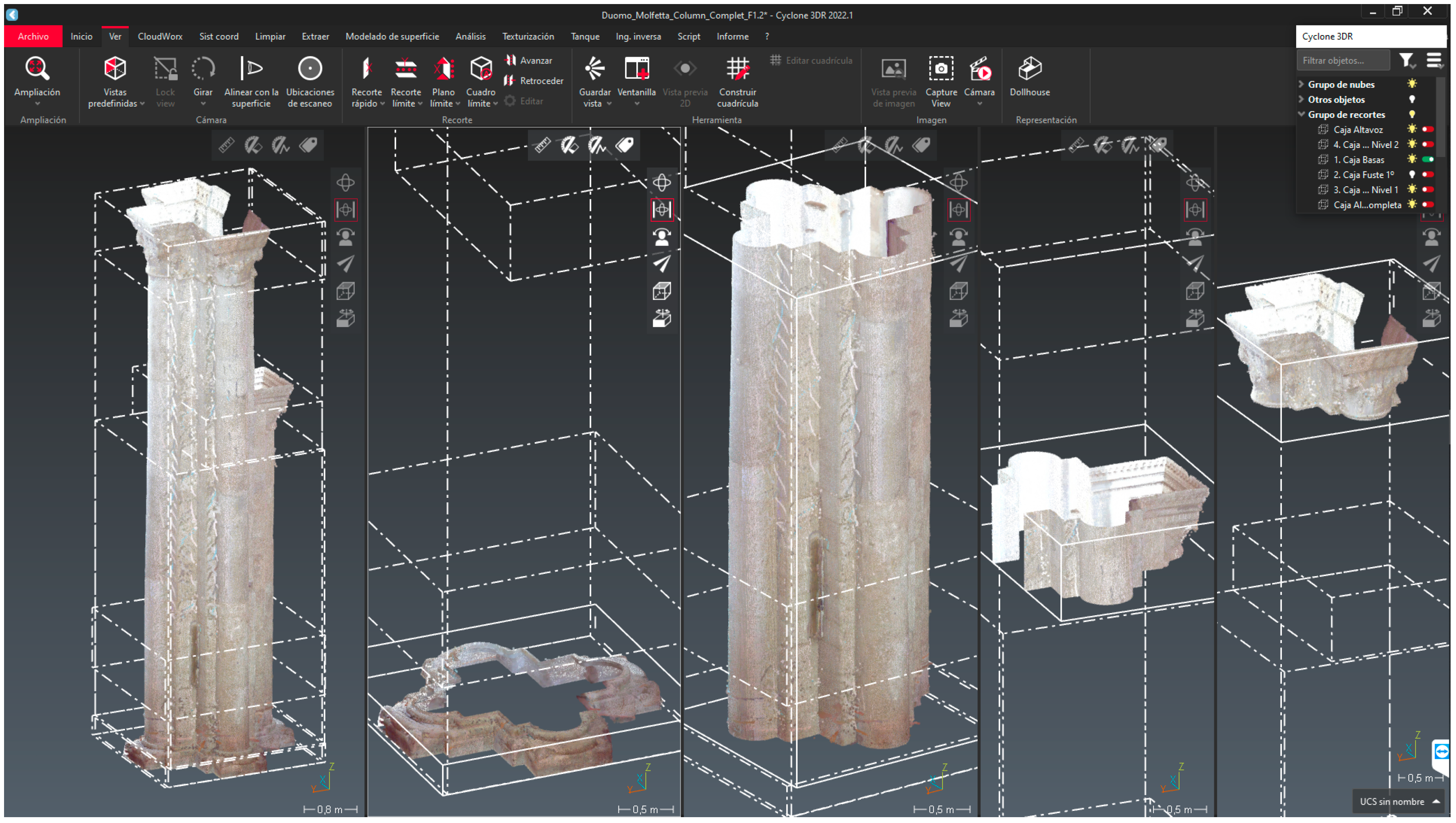
Figure 6.
(a) Semantic segmentation of the point cloud (TLS) in the Cyclone 3DR environment, showing the typologies delimited with box; (b) Groups of points are inserted and converted into parametric objects in the HBIM Project of the Duomo di Molfetta (Archicad 27).
Figure 6.
(a) Semantic segmentation of the point cloud (TLS) in the Cyclone 3DR environment, showing the typologies delimited with box; (b) Groups of points are inserted and converted into parametric objects in the HBIM Project of the Duomo di Molfetta (Archicad 27).
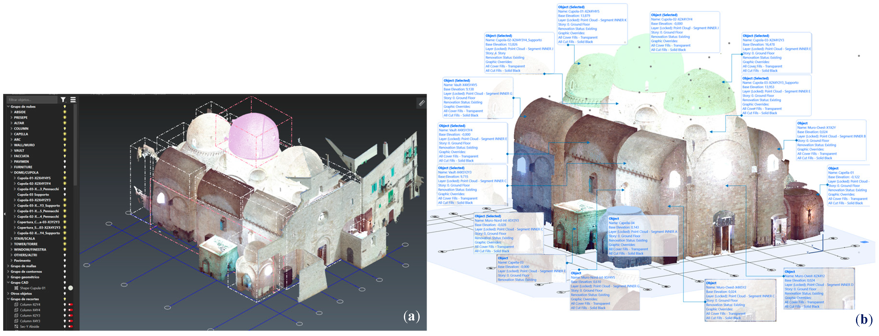
Figure 7.
(a) Plan of the Point Cloud of the Duomo of Molfetta and position of the Column-X4Y2; (b) 3D section to the interior point cloud and selection of the Column-X4Y2 object, inserted in format. e57 in the HBIM project; (c) The portion is converted into an ArchiCAD library object (.gsm /.lcf).
Figure 7.
(a) Plan of the Point Cloud of the Duomo of Molfetta and position of the Column-X4Y2; (b) 3D section to the interior point cloud and selection of the Column-X4Y2 object, inserted in format. e57 in the HBIM project; (c) The portion is converted into an ArchiCAD library object (.gsm /.lcf).
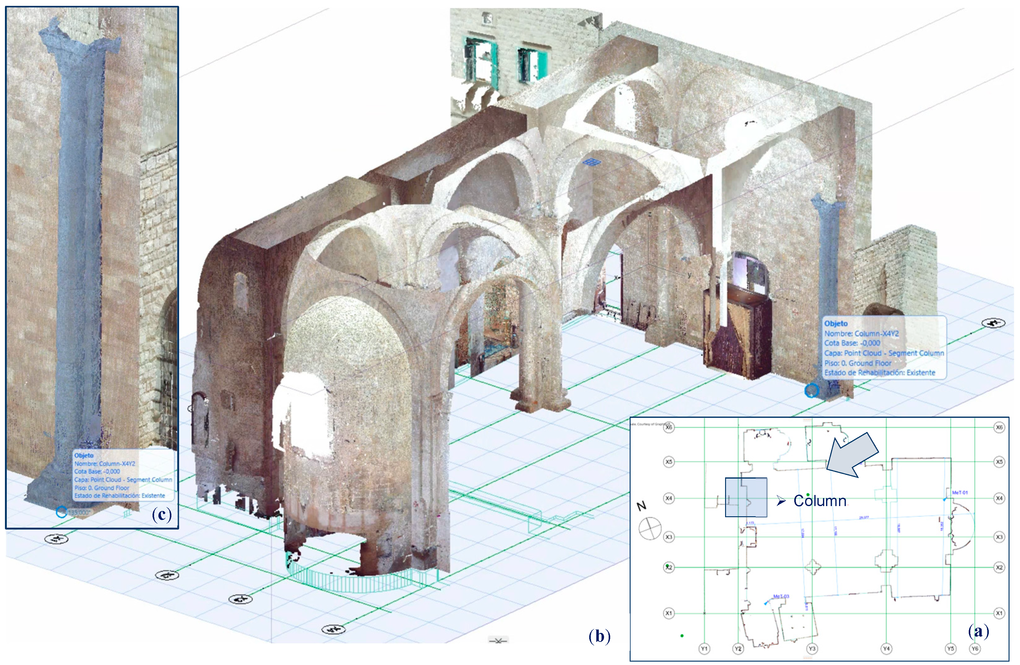
Figure 8.
Column-X4Y2 classification: Walls (brown); Soils (cyan); Roofs (green); Others (in gray). The irregularities of the shaft are classified as Other, as well as the carved decoration of the capital (images captured from the Cyclone 3DR interface).
Figure 8.
Column-X4Y2 classification: Walls (brown); Soils (cyan); Roofs (green); Others (in gray). The irregularities of the shaft are classified as Other, as well as the carved decoration of the capital (images captured from the Cyclone 3DR interface).
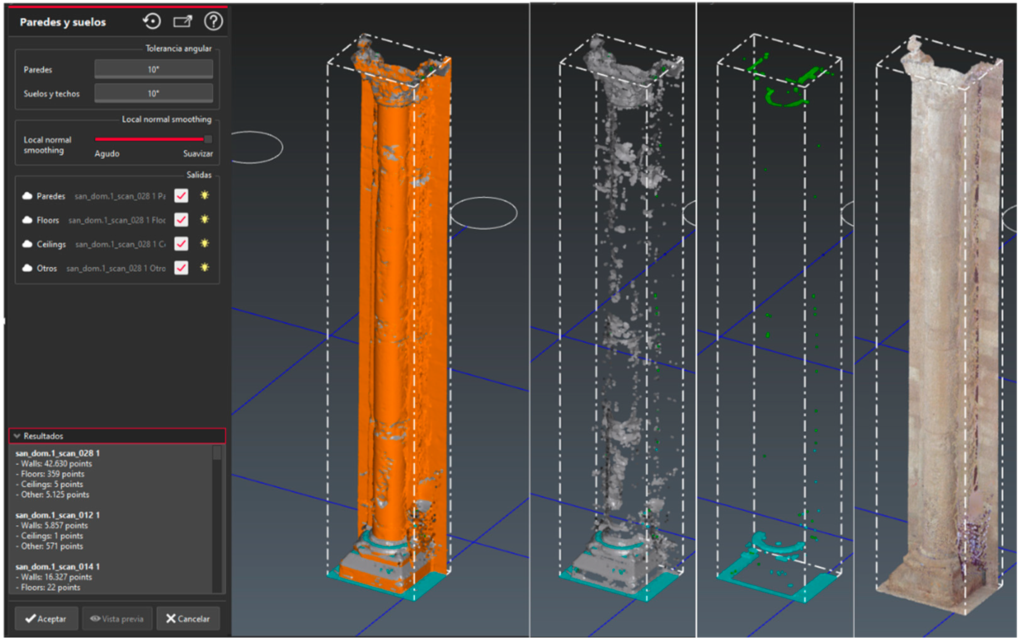
Figure 9.
Image of the Column-X4Y2, once it completes the last phase of points classification: 1,742,768 – 89% (Paredes/Walls, in brown) and 208,711 – 11% (Other, in grey). (Images captured from the Cyclone 3DR interface).
Figure 9.
Image of the Column-X4Y2, once it completes the last phase of points classification: 1,742,768 – 89% (Paredes/Walls, in brown) and 208,711 – 11% (Other, in grey). (Images captured from the Cyclone 3DR interface).
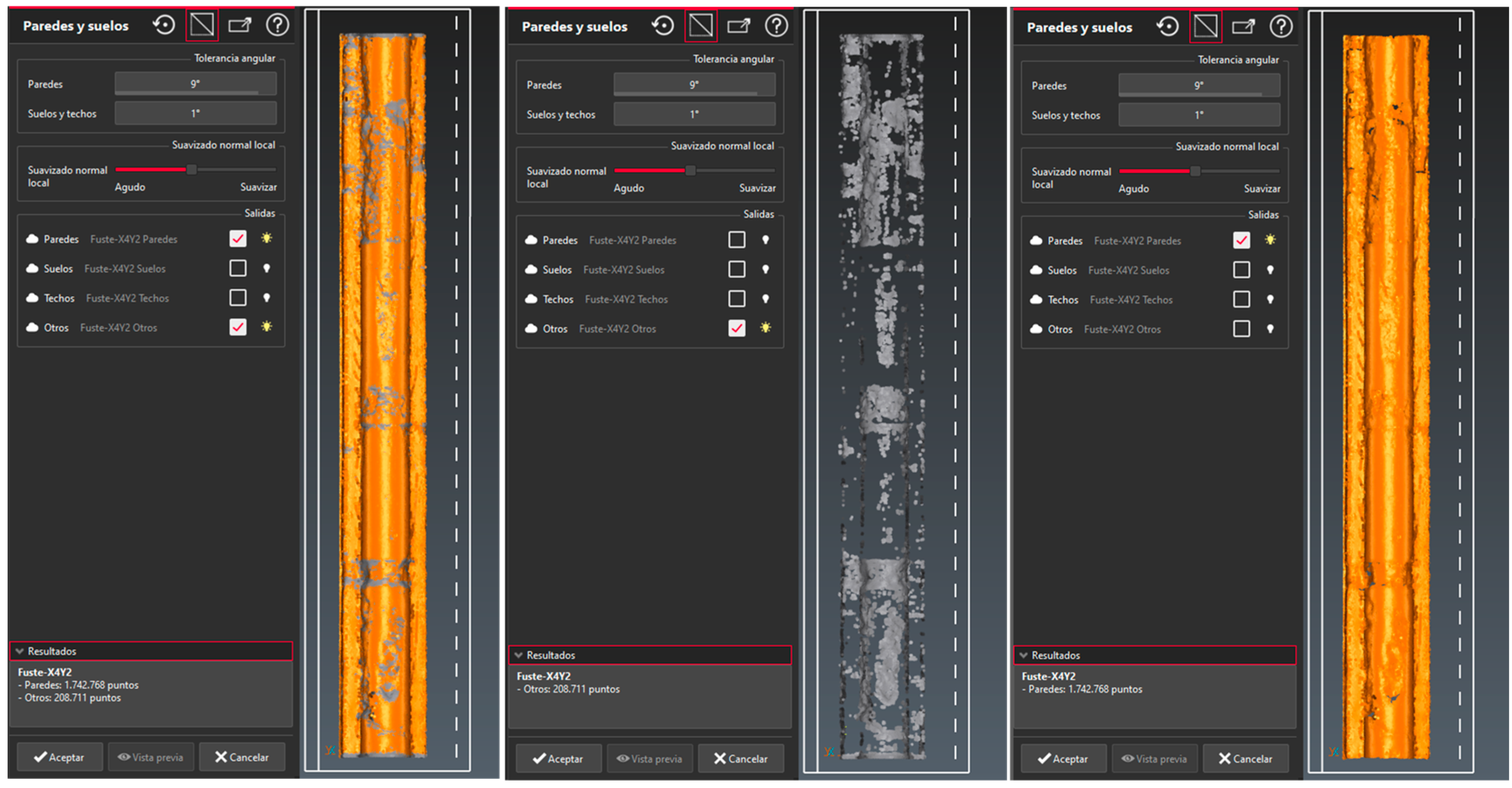
Figure 10.
Column modeled in ArchiCAD and compared with the mesh imported from Cyclone (IFC format). It is analysed and dimensioned to extract the collapses suffered by the column: (a) - 0.744º in the direction of the west façade; (b) the horizontal section at +7.36 m ours the deviation in -X (red color). (Images captured from the Archicad interface).
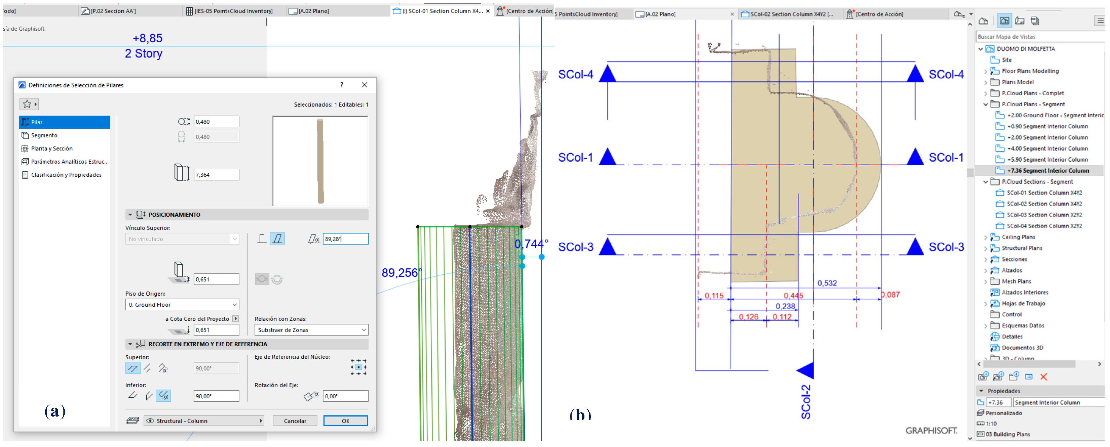
Figure 11.
Theoretical model exported in IFC format and the mesh generated from the point cloud; Section plans made to the shaft every 15 cm (images captured from the Cyclone 3DR interface).
Figure 11.
Theoretical model exported in IFC format and the mesh generated from the point cloud; Section plans made to the shaft every 15 cm (images captured from the Cyclone 3DR interface).
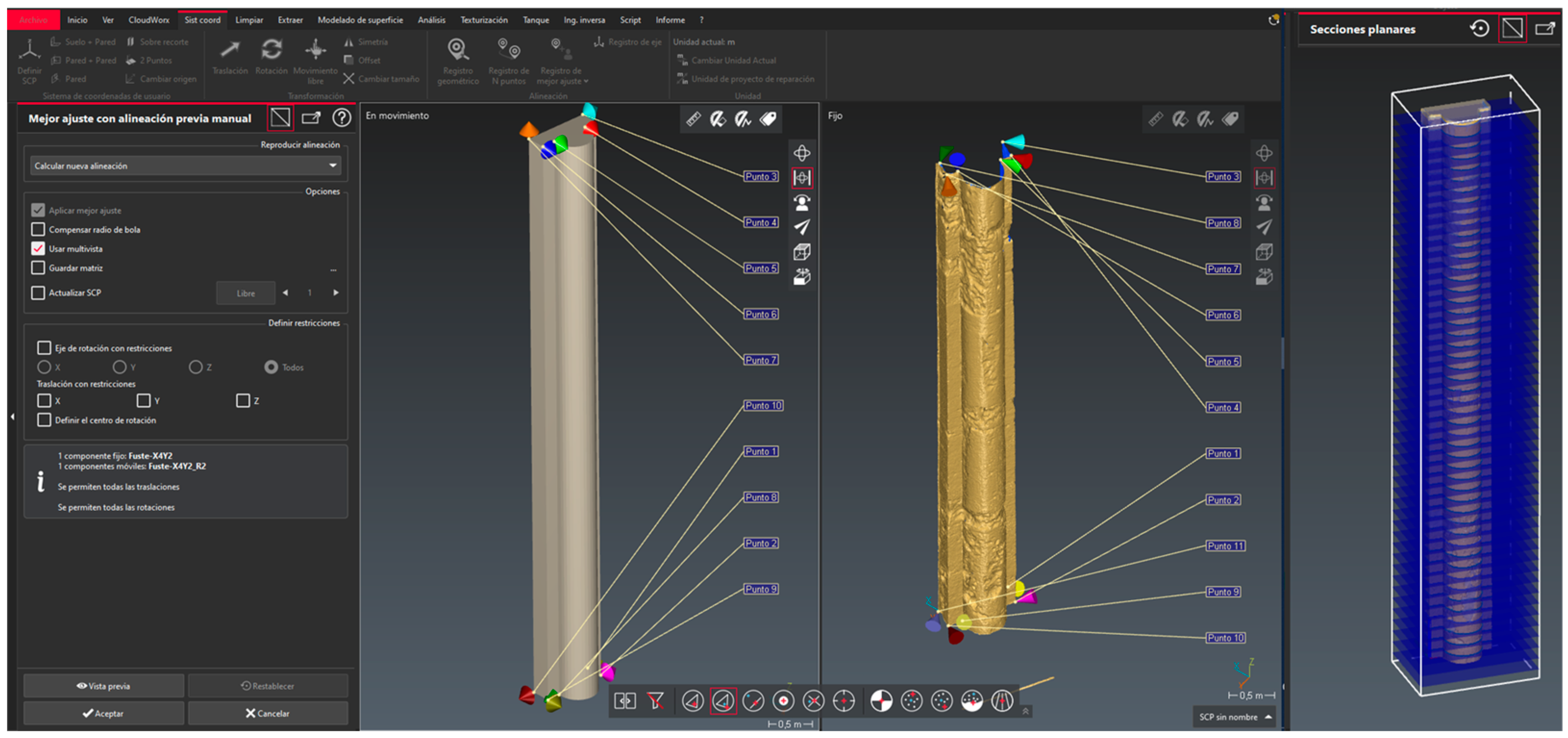
Figure 12.
Results of the comparison between theoretical model and real model with the color result graph (images captured from the Cyclone 3DR interface).
Figure 12.
Results of the comparison between theoretical model and real model with the color result graph (images captured from the Cyclone 3DR interface).
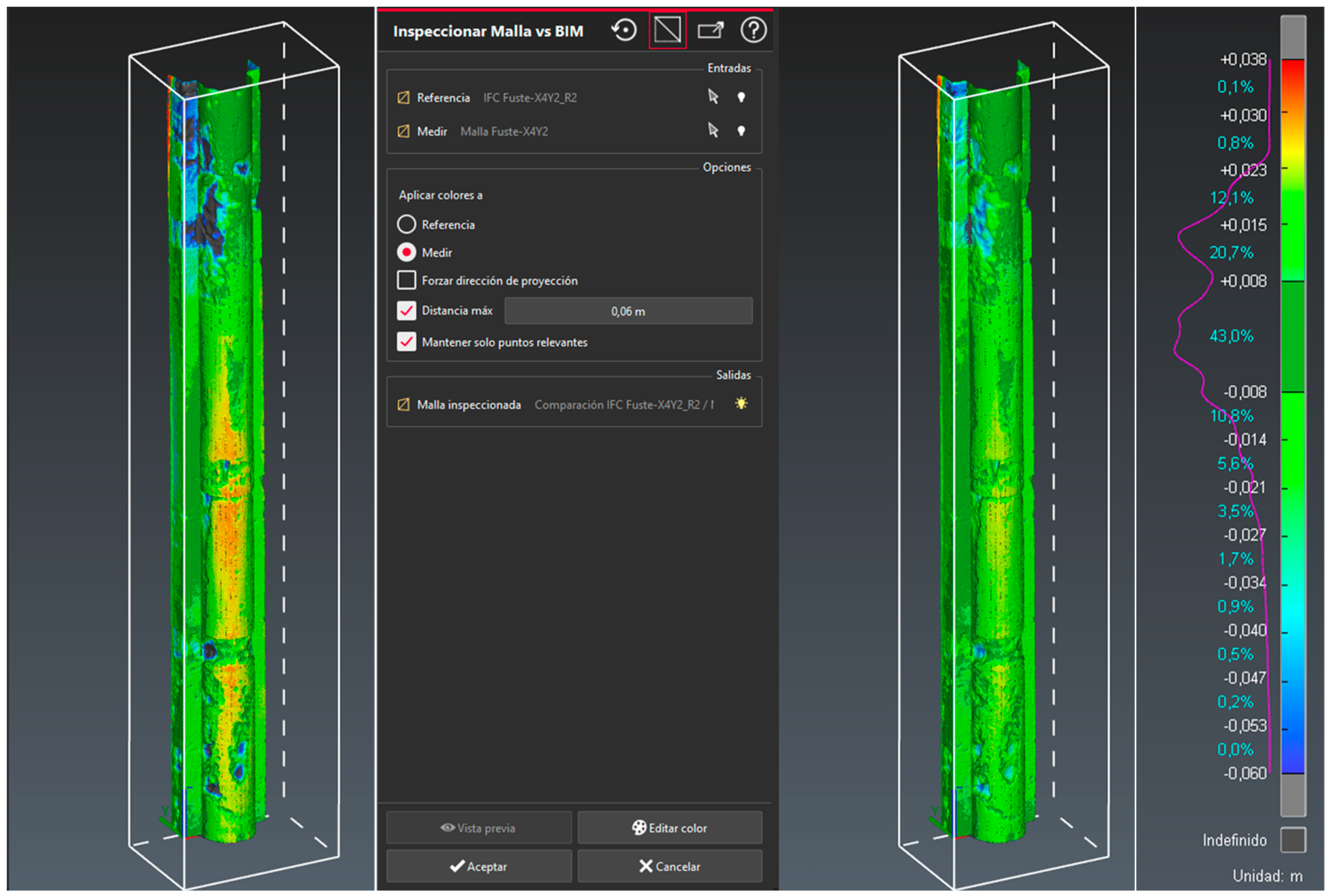
Figure 13.
Sections taken from the Report to compare the Point Clouds with the Theoretical Surface of the Shaft Column- X4Y2 (Cyclone 3DR).
Figure 13.
Sections taken from the Report to compare the Point Clouds with the Theoretical Surface of the Shaft Column- X4Y2 (Cyclone 3DR).
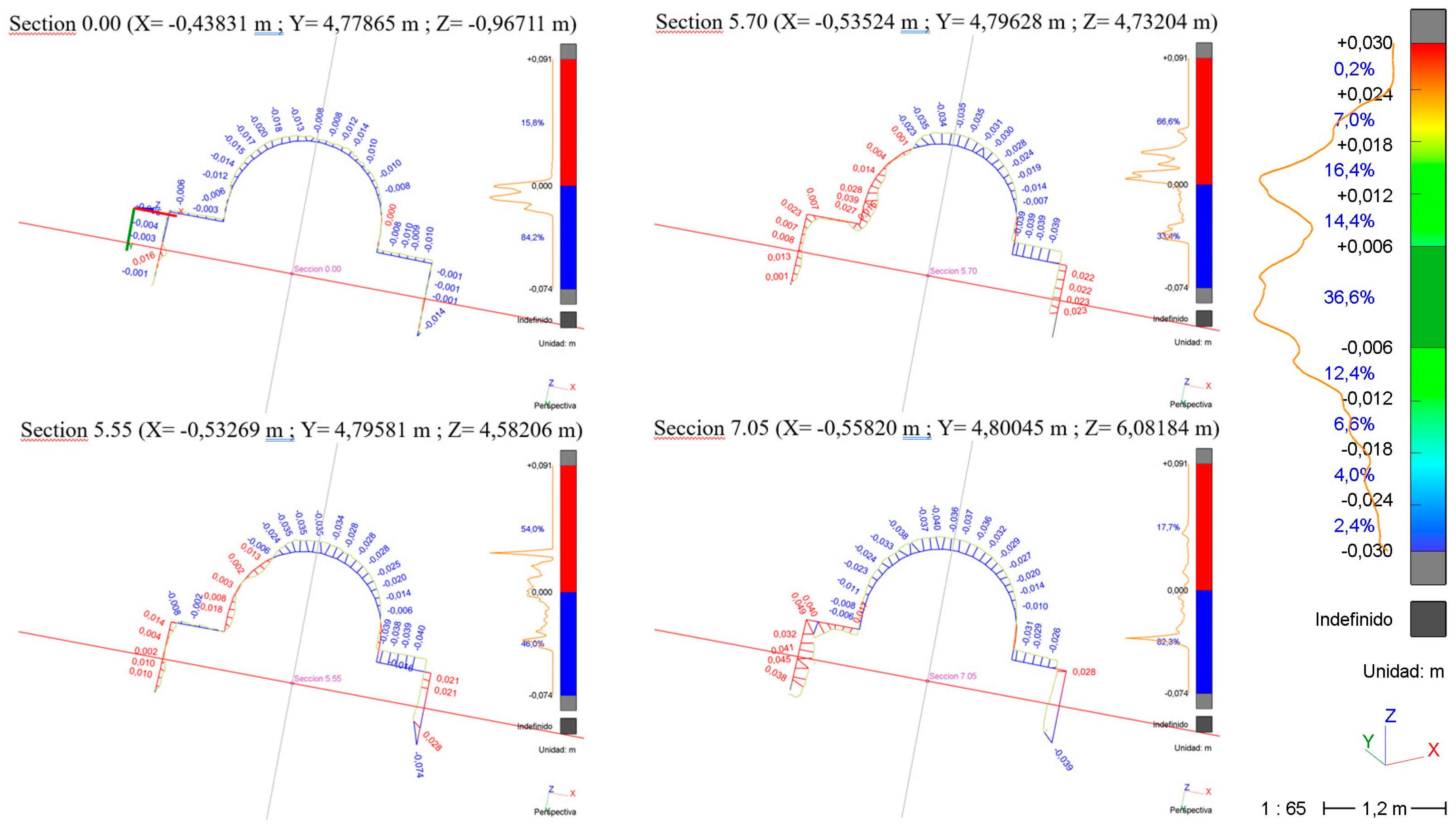
Figure 14.
(a) TLS point cloud referenced model (Archicad 27); (b) Simplified parametric model (HBIM project); (c) Exported IFC model, with the properties of the elements (BIMvision).
Figure 14.
(a) TLS point cloud referenced model (Archicad 27); (b) Simplified parametric model (HBIM project); (c) Exported IFC model, with the properties of the elements (BIMvision).
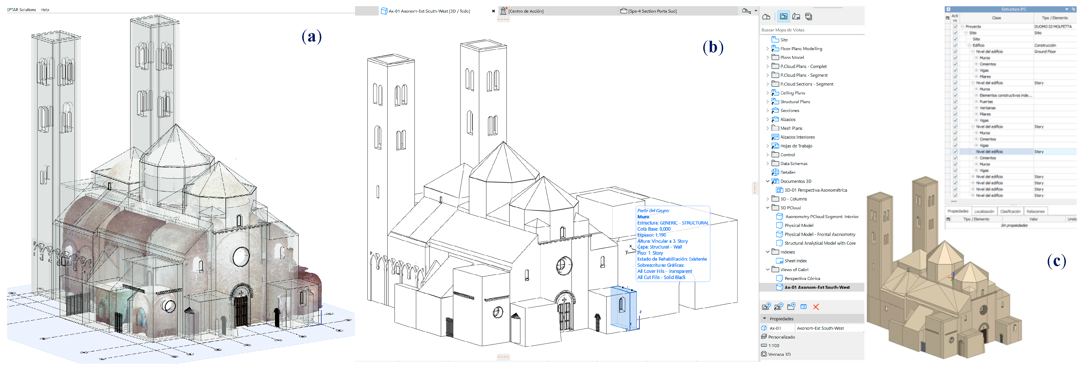
Figure 15.
Marking and selection of the parameters associated with the filtered elements from the same scheme of the HBIM Project: the PointCloud-Column portion is classified as a Pilaster (image captured from the Archicad interface).
Figure 15.
Marking and selection of the parameters associated with the filtered elements from the same scheme of the HBIM Project: the PointCloud-Column portion is classified as a Pilaster (image captured from the Archicad interface).
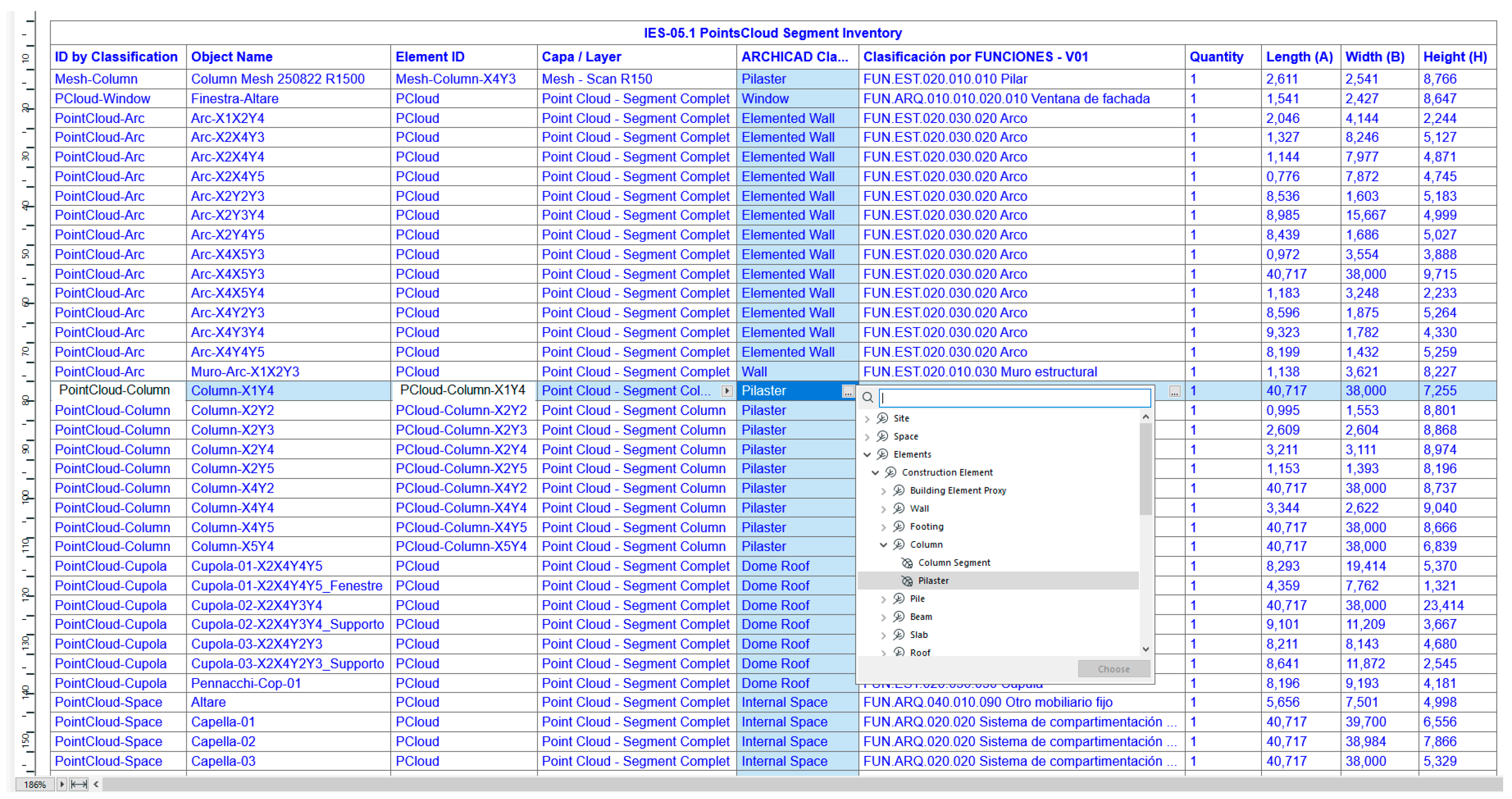
Figure 16.
Schema of Classified PCloud-Column Elements, incorporating the properties Construction Type, Decription of Tecnique, Technology, Class of Material, Mortar. It interacts in the HBIM project by allowing a multiselection of items by properties (image captured from the Archicad interface).
Figure 16.
Schema of Classified PCloud-Column Elements, incorporating the properties Construction Type, Decription of Tecnique, Technology, Class of Material, Mortar. It interacts in the HBIM project by allowing a multiselection of items by properties (image captured from the Archicad interface).
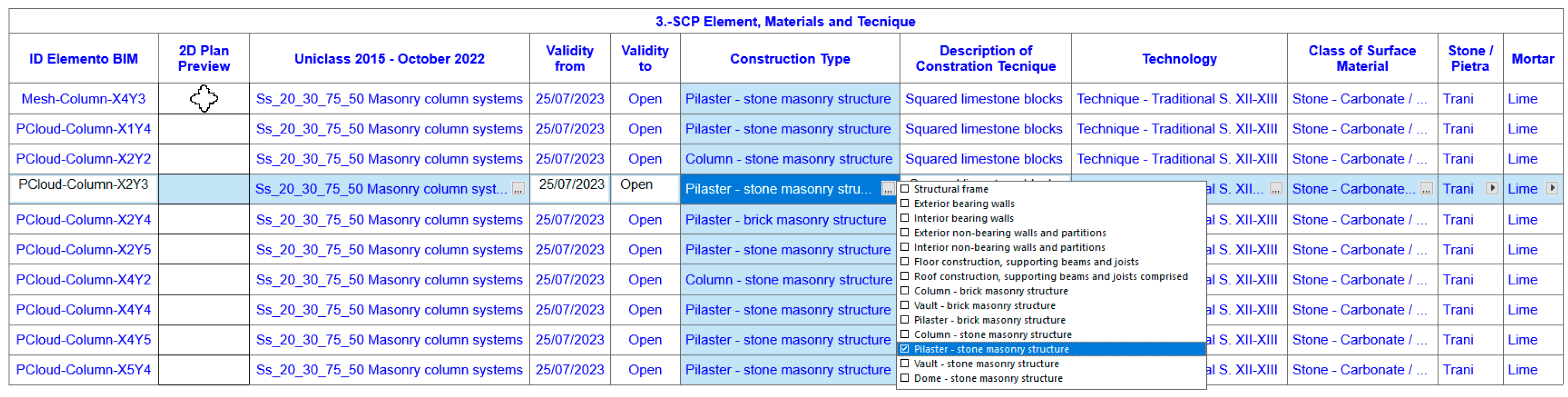
Figure 17.
Diagram showing the Decays of the columns of the Duomo. All columns are classified by their Structural Function and Phase Execution of the Preservation Project (image captured from the Archicad interface).
Figure 17.
Diagram showing the Decays of the columns of the Duomo. All columns are classified by their Structural Function and Phase Execution of the Preservation Project (image captured from the Archicad interface).
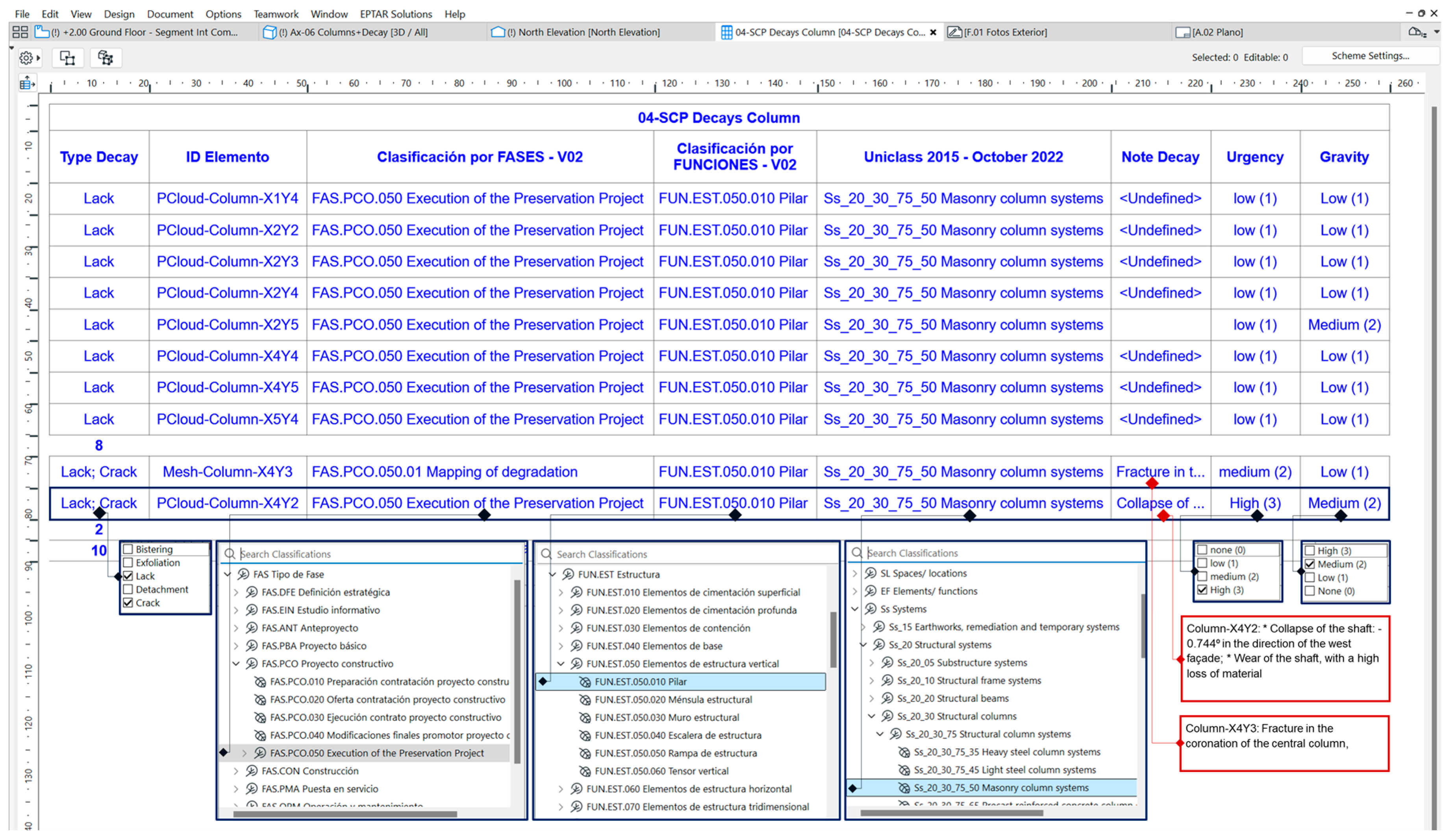
Figure 18.
Object Selection Settings of Column-X4Y3, where properties created in Preservation Processes are available. In the Decay category, the following are applied: Type, Urgency, Seriousness and Note Decay: Fracture in the coronation of the central column, transversal to the central nave (image captured from the Archicad interface).
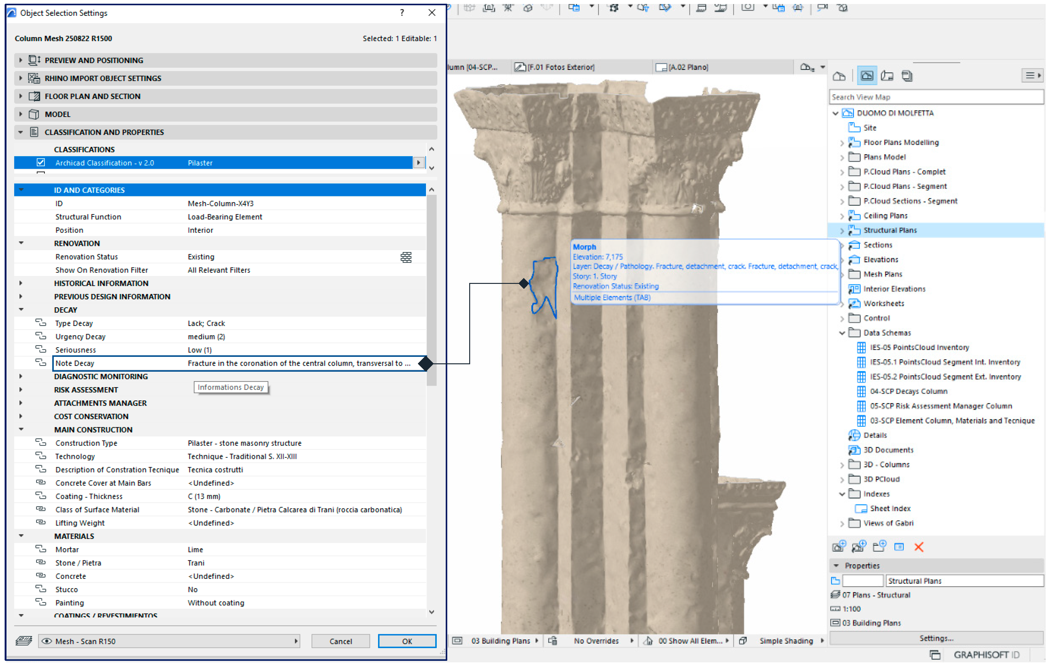
Figure 19.
The mark of deterioration is enriched with the properties of the Risk Assessment category. For the Activity category, the following options have been checked: Visual, Instrumental, Intervention, Consolidation. En Activity type: Re-adhesion by pins, Stuffed same material. (Archicad).
Figure 19.
The mark of deterioration is enriched with the properties of the Risk Assessment category. For the Activity category, the following options have been checked: Visual, Instrumental, Intervention, Consolidation. En Activity type: Re-adhesion by pins, Stuffed same material. (Archicad).
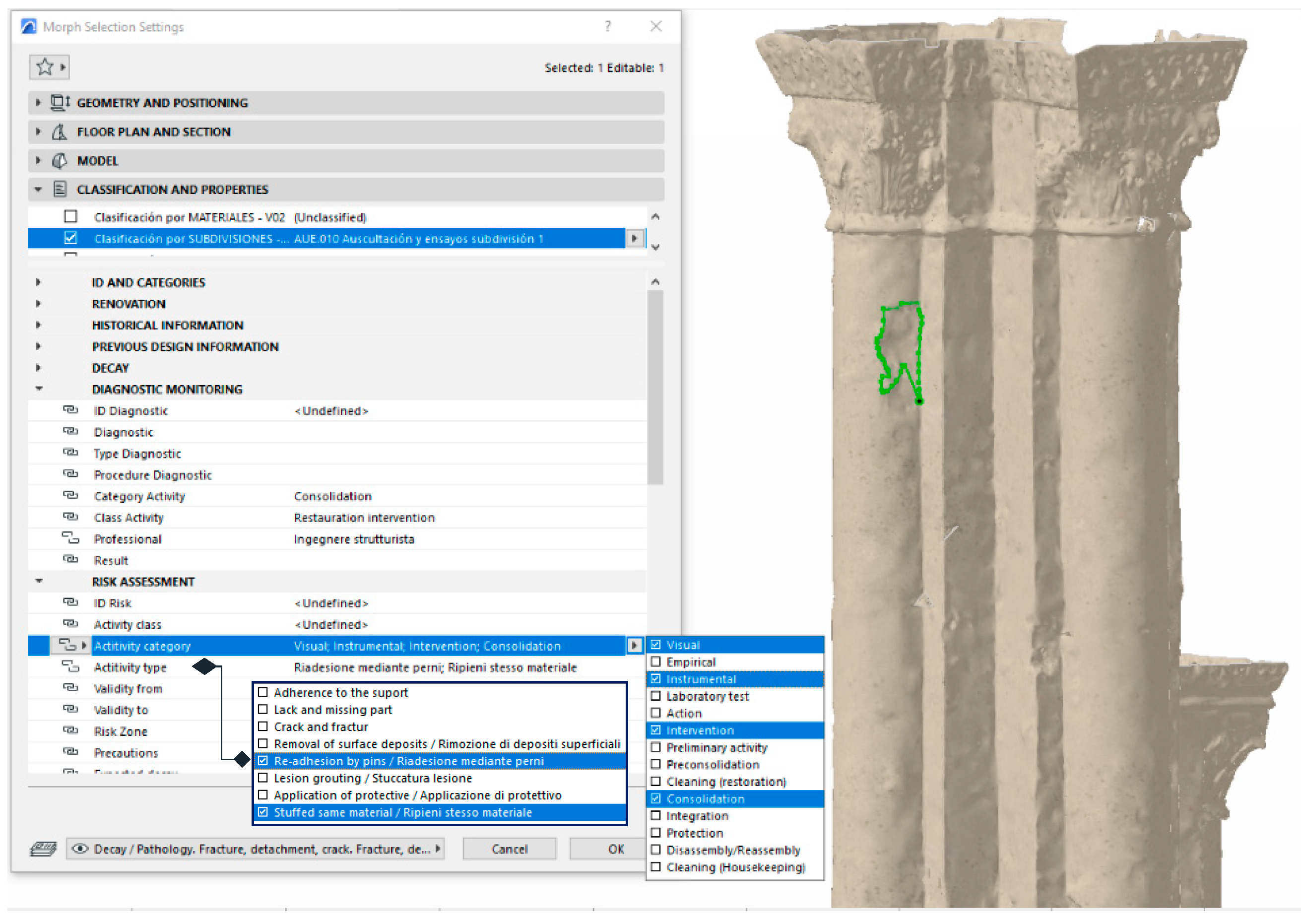

Table 2.
Data of the deviations (average, minimum, maximum) in each horizontal section given to the shaft of the Column-X4Y2.
Table 2.
Data of the deviations (average, minimum, maximum) in each horizontal section given to the shaft of the Column-X4Y2.
| Section | Desv. Pr. (m) | D. mín. (m) | D. máx. (m) |
| Section 0.00 | -0,00653 | -0,01994 | 0,01553 |
| Section 0.15 | -0,00915 | -0,02205 | 0,00932 |
| Section 0.30 | -0,00600 | -0,02157 | 0,04881 |
| Section 0.45 | -0,00450 | -0,02339 | 0,03249 |
| Section 0.60 | -0,00589 | -0,02378 | 0,03059 |
| Section 0.75 | -0,00713 | -0,02487 | 0,01258 |
| Section 0.90 | -0,00825 | -0,02659 | 0,01728 |
| Section 1.05 | -0,01109 | -0,02765 | 0,00703 |
| Section 1.20 | -0,00924 | -0,05111 | 0,01171 |
| Section 1.35 | -0,00987 | -0,03155 | 0,01161 |
| Section 1.50 | -0,01105 | -0,04798 | 0,02569 |
| Section 1.65 | 0,00469 | -0,04241 | 0,03671 |
| Section 1.80 | -0,00850 | -0,03267 | 0,01419 |
| Section 1.95 | -0,01257 | -0,03231 | 0,00752 |
| Section 2.10 | -0,01141 | -0,03297 | 0,00917 |
| Section 2.25 | -0,01247 | -0,03458 | 0,00816 |
| Section 2.40 | -0,01242 | -0,03558 | 0,00757 |
| Section 2.55 | -0,01405 | -0,03712 | 0,00942 |
| Section 2.70 | -0,01369 | -0,03796 | 0,01120 |
| Section 2.85 | -0,01169 | -0,03915 | 0,01525 |
| Section 3.00 | -0,01383 | -0,04137 | 0,01250 |
| Section 3.15 | -0,00514 | -0,03706 | 0,02599 |
| Section 3.30 | -0,00977 | -0,03961 | 0,01360 |
| Section 3.45 | -0,01252 | -0,03274 | 0,01491 |
| Section | Desv. Pr. (m) | D. mín. (m) | D. máx.(m) |
| Section 3.60 | -0,01769 | -0,04245 | 0,01260 |
| Section 3.75 | -0,01568 | -0,04240 | 0,01317 |
| Section 3.90 | -0,01411 | -0,04274 | 0,01360 |
| Section 4.05 | -0,01457 | -0,04200 | 0,01447 |
| Section 4.20 | -0,01442 | -0,04138 | 0,01375 |
| Section 4.35 | -0,01391 | -0,04030 | 0,01342 |
| Section 4.50 | -0,01459 | -0,04045 | 0,01619 |
| Section 4.65 | -0,01557 | -0,04142 | 0,01712 |
| Section 4.80 | -0,01455 | -0,04007 | 0,01963 |
| Section 4.95 | -0,02316 | -0,04074 | 0,01991 |
| Section 5.10 | -0,00972 | -0,03993 | 0,02097 |
| Section 5.25 | -0,01144 | -0,03948 | 0,02201 |
| Section 5.40 | -0,00598 | -0,04435 | 0,09054 |
| Section 5.55 | -0,00173 | -0,07380 | 0,02808 |
| Section 5.70 | 0,00142 | -0,03929 | 0,03912 |
| Section 5.85 | -0,00186 | -0,05727 | 0,05121 |
| Section 6.00 | 0,00190 | -0,03662 | 0,03283 |
| Section 6.15 | -0,00675 | -0,03715 | 0,02814 |
| Section 6.30 | -0,00486 | -0,03500 | 0,03209 |
| Section 6.45 | -0,00518 | -0,03766 | 0,03320 |
| Section 6.60 | 0,00161 | -0,03850 | 0,04433 |
| Section 6.75 | -0,01300 | -0,03837 | 0,03851 |
| Section 6.90 | -0,00952 | -0,03936 | 0,03022 |
| Section 7.05 | -0,01761 | -0,04033 | 0,04967 |
Table 3.
Scheme Risk Assessment Manager Column & Pilater of the HBIM Duomo di Molfetta project, exported in Excel format (xlsx).
Table 3.
Scheme Risk Assessment Manager Column & Pilater of the HBIM Duomo di Molfetta project, exported in Excel format (xlsx).
| 05-SCP Risk Assessment Manager Column / Pilaster (pag.1) | ||||||||
| ID Risk (String) | ID Elemento BIM | Uniclass 2015 - October 2022 | Type Decay | Actitivity type | Activity class | Actitivity category | Risk Zone | Interactions (Option Set) |
| Ri-001.F1.PR019 | Mesh-Column-X4Y3 | Ss_20_30_75_50 Masonry column systems | Lack; Crack | Lack and missing part; Crack and fractur | Control/Inspection; Inspection | Visual | Partial element | With the horizontal support structure. |
| Ri-002.F1.PR019 | PCloud-Column-X4Y2 | Ss_20_30_75_50 Masonry column systems | Lack; Crack | Lack and missing part | Control/Inspection; Inspection | Visual; Empirical | Whole element | With the horizontal support structure. |
| Ri-003.F1.PR019 | PCloud-Column-X1Y4 | Ss_20_30_75_50 Masonry column systems | Lack | Lack and missing part | Inspection | Visual | Partial element | With the horizontal support structure. |
| Ri-003.F1.PR019 | PCloud-Column-X2Y2 | Ss_20_30_75_50 Masonry column systems | Lack | Lack and missing part | Inspection | Visual | Partial element | With the horizontal support structure. |
| Ri-003.F1.PR019 | PCloud-Column-X2Y3 | Ss_20_30_75_50 Masonry column systems | Lack | Lack and missing part; Crack and fractur | Control/Inspection; Inspection | Visual; Instrumental | Whole element | With the horizontal support structure. |
| Ri-003.F1.PR019 | PCloud-Column-X2Y4 | Ss_20_30_75_50 Masonry column systems | Lack | Lack and missing part | Inspection | Visual | Partial element | With the horizontal support structure. |
| Ri-003.F1.PR019 | PCloud-Column-X2Y5 | Ss_20_30_75_50 Masonry column systems | Lack | Lack and missing part | Inspection | Visual | Partial element | With the horizontal support structure. |
| Ri-003.F1.PR019 | PCloud-Column-X4Y4 | Ss_20_30_75_50 Masonry column systems | Lack | Lack and missing part | Inspection | Visual | Partial element | With the horizontal support structure. |
| Ri-003.F1.PR019 | PCloud-Column-X4Y5 | Ss_20_30_75_50 Masonry column systems | Lack | Lack and missing part | Inspection | Visual | Partial element | With the horizontal support structure. |
| Ri-003.F1.PR019 | PCloud-Column-X5Y4 | Ss_20_30_75_50 Masonry column systems | Lack | Lack and missing part | Inspection | Visual | Partial element | With the horizontal support structure. |
| 05-SCP Risk Assessment Manager Column / Pilaster (pag.2) | ||||||||
| ID Risk (String) | ID Elemento BIM | Precautions | Validity from | Validity to | Construction Type (Option Set) | Technology (Option Set) | Class of Surface Material (Option Set) | Mortar |
| Ri-001.F1.PR019 | Mesh-Column-X4Y3 | <?> | 25/07/2023 | Open | Pilaster - stone masonry structure | Technique - Traditional S. XII-XIII | Stone - Carbonate / Pietra Calcarea di Trani (roccia carbonatica) | Lime |
| Ri-002.F1.PR019 | PCloud-Column-X4Y2 | <?> | 25/07/2023 | Open | Column - stone masonry structure | Technique - Traditional S. XII-XIII | Stone - Carbonate / Pietra Calcarea di Trani (roccia carbonatica) | Lime |
| Ri-003.F1.PR019 | PCloud-Column-X1Y4 | <?> | 25/07/2023 | Open | Pilaster - stone masonry structure | Technique - Traditional S. XII-XIII | Stone - Carbonate / Pietra Calcarea di Trani (roccia carbonatica) | Lime |
| Ri-003.F1.PR019 | PCloud-Column-X2Y2 | <?> | 25/07/2023 | Open | Column - stone masonry structure | Technique - Traditional S. XII-XIII | Stone - Carbonate / Pietra Calcarea di Trani (roccia carbonatica) | Lime |
| Ri-003.F1.PR019 | PCloud-Column-X2Y3 | <?> | 25/07/2023 | Open | Pilaster - stone masonry structure | Technique - Traditional S. XII-XIII | Stone - Carbonate / Pietra Calcarea di Trani (roccia carbonatica) | Lime |
| Ri-003.F1.PR019 | PCloud-Column-X2Y4 | <?> | 25/07/2023 | Open | Pilaster - brick masonry structure | Technique - Traditional S. XII-XIII | Stone - Carbonate / Pietra Calcarea di Trani (roccia carbonatica) | Lime |
| Ri-003.F1.PR019 | PCloud-Column-X2Y5 | <?> | 25/07/2023 | Open | Pilaster - stone masonry structure | Technique - Traditional S. XII-XIII | Stone - Carbonate / Pietra Calcarea di Trani (roccia carbonatica) | Lime |
| Ri-003.F1.PR019 | PCloud-Column-X4Y4 | <?> | 25/07/2023 | Open | Pilaster - stone masonry structure | Technique - Traditional S. XII-XIII | Stone - Carbonate / Pietra Calcarea di Trani (roccia carbonatica) | Lime |
| Ri-003.F1.PR019 | PCloud-Column-X4Y5 | <?> | 25/07/2023 | Open | Pilaster - stone masonry structure | Technique - Traditional S. XII-XIII | Stone - Carbonate / Pietra Calcarea di Trani (roccia carbonatica) | Lime |
| Ri-003.F1.PR019 | PCloud-Column-X5Y4 | <?> | 25/07/2023 | Open | Pilaster - stone masonry structure | Technique - Traditional S. XII-XIII | Stone - Carbonate / Pietra Calcarea di Trani (roccia carbonatica) | Lime |
Table 4.
Editing the data schema exported in Excel format (xlxs) from Archicad, Interoperability>Classification and Properties option> Exports property values from the Schema.
Table 4.
Editing the data schema exported in Excel format (xlxs) from Archicad, Interoperability>Classification and Properties option> Exports property values from the Schema.
| ID Risk (String) | ID Elemento BIM | Uniclass 2015 - October 2022 | Type Decay (Option Set) | Actitivity type (Option Set) | Activity class (Option Set) | Actitivity category (Option Set) | Risk Zone (Option Set) |
|---|---|---|---|---|---|---|---|
| Ri-001.F1.PR019 | Mesh-Column-X4Y3 | Ss_20_30_75_50 Masonry column systems | Lack; Crack | Lack and missing part; Crack and fractur | Control; Inspection | Visual | Partial element |
| Ri-002.F1.PR019 | PCloud-Column-X4Y2 | Ss_20_30_75_50 Masonry column systems | Lack; Crack | Lack and missing part | Control; Inspection | Visual; Empirical | Whole element |
| Ri-003.F1.PR019 | PCloud-Column-X1Y4 | Ss_20_30_75_50 Masonry column systems | Lack | Lack and missing part | Inspection | Visual | Partial element |
| Ri-003.F1.PR019 | PCloud-Column-X2Y2 | Ss_20_30_75_50 Masonry column systems | Lack | Lack and missing part | Inspection | Visual | Partial element |
| Ri-003.F1.PR019 | PCloud-Column-X2Y3 | Ss_20_30_75_50 Masonry column systems | Lack | Lack and missing part; Crack and fractur | Control; Inspection | Visual; Instrumental | Whole element |
| Ri-003.F1.PR019 | PCloud-Column-X2Y4 | Ss_20_30_75_50 Masonry column systems | Lack | Lack and missing part | Inspection | Visual | Partial element |
| Ri-003.F1.PR019 | PCloud-Column-X2Y5 | Ss_20_30_75_50 Masonry column systems | Lack | Lack and missing part | Inspection | Visual | Partial element |
| Ri-003.F1.PR019 | PCloud-Column-X4Y4 | Ss_20_30_75_50 Masonry column systems | Lack | Lack and missing part | Inspection | Visual | Partial element |
| Ri-003.F1.PR019 | PCloud-Column-X4Y5 | Ss_20_30_75_50 Masonry column systems | Lack | Lack and missing part | Inspection | Visual | Partial element |
| Ri-003.F1.PR019 | PCloud-Column-X5Y4 | Ss_20_30_75_50 Masonry column systems | Lack | Lack and missing part | Inspection | Visual | Partial element |
Disclaimer/Publisher’s Note: The statements, opinions and data contained in all publications are solely those of the individual author(s) and contributor(s) and not of MDPI and/or the editor(s). MDPI and/or the editor(s) disclaim responsibility for any injury to people or property resulting from any ideas, methods, instructions or products referred to in the content. |
© 2024 by the authors. Licensee MDPI, Basel, Switzerland. This article is an open access article distributed under the terms and conditions of the Creative Commons Attribution (CC BY) license (https://creativecommons.org/licenses/by/4.0/).
Copyright: This open access article is published under a Creative Commons CC BY 4.0 license, which permit the free download, distribution, and reuse, provided that the author and preprint are cited in any reuse.


