Submitted:
07 August 2024
Posted:
08 August 2024
You are already at the latest version
Abstract
The literature analysis did not indicate any studies on fluorination tests of carbon nanocomposite coatings doped with transition metals of the nc-MeC/a-C type. This was the motivation for undertaking research in this area. As a model coating to investigate the effect of fluorination in a tetrafluoromethane (CF4) atmosphere, a nano-composite carbon coating doped with chromium nc-CrC/a-C produced by magnetron sputtering from graphite targets and the use of a Pulse-DC type medium frequency power supply was chosen [6]. After deposition of the gradient CrCN adhesive sublayer, fluorination of the main coating was conducted in a reactive mode in an (Ar+CF4) atmosphere at various CF4 contents. It was observed that the presence of CF4 in the atmosphere resulted in a reduced amount of chromium carbides formed in favor of chromium fluorides. So far, this is an observation that seems unnoticed by the carbon coatings researchers. Fluorine was assumed to bond much more readily to carbon than to chromium, due to the stability of tetrafluoromethane (CF4). The opposite seems to be true. The mechanical properties (nano-hardness and Young's modulus) and tribological properties in the 'pin-on-disc' friction pair are presented, along with the analysis of bonds occurring between chromium, carbon, and fluorine (XPS).
Keywords:
fluorination of carbon nano-composite coatings
; chromium fluorides
; reactive magnetron sputtering in Ar + CF4 atmosphere
1. Introduction
Carbon coatings have been known for many years. Different bond contributions of sp2 or sp3 hybridization allow for a wide range of applications. In addition to PolyCrystalline Diamond coatings (PCDs), there are typical amorphous a-C coatings and very hard tetrahedral ta-C coatings. All carbon coatings can be hydrogenated and the level of hydrogenation affects the tribological properties [1,2]. The addition of transition metals (W, Ti, Cr, and others) allows nanocomposite coatings to be obtained, where the carbides of these metals are nanometric in size and increase wear resistance in the friction contact [2,3,4,5,6]. The contribution of carbides, their type, and size enable control over the properties, e.g. mechanical [2]. Besides the typical carbide-forming metals, carbon coatings can be doped with non-metals such as Si, O, N, or F [1,2,7]. While the effects of the first three mentioned elements are quite well described in the literature, there is little work on the influence of fluorine on carbon coatings. Donnett's 1998 review paper [1] includes a summary of contemporary work on fluorinated carbon coatings. However, it describes only a few reports [8,9,10,11,12,13] about the effect of fluorine on reducing surface energy, increasing stresses in fluorinated carbon coatings, friction, and wear of such coatings, most often produced by the RF PA CVD method, in the presence of hydrogen. The most interesting thing, however, based on [13], the existence of unbound fluorine in the coating was described meaning that not all fluorine radicals were chemically connected to the carbon matrix. Favorable tribological features of carbon coatings with low fluorine content (up to 20%) were also shown. Unbound fluorine to the matrix increases stresses in the coatings and limits the ability to transfer loads in the friction contact.
The Authors of [7] pointed out that fluorination can relate to the bulk of the coatings as well as exclusively fluorinating of the surface of the finished coating in hydrogen fluoride plasma. Modifying only the surface of the carbon coating for frictional contact work will not yield the expected results as the thin film will be quickly removed. Adding fluorine to the growing volume of the coating allows the coating to perform longer due to the disclosure of new, fluorinated portions of materials, as well as obtaining other interesting features, e.g. low dielectric constant (low-k) materials for electronic applications. The authors of [7] highlight the small number of articles available about fluorination of carbon coatings produced not only by PECVD but also by reactive sputtering or from a PTFE target. The former method, by the nature of the gaseous precursors used, contains hydrogen in the atmosphere. These works concern the C-H-F system and not only the fluorination of a-C coatings.
The work [7], which was published in 2011, also shows that the interest of researchers in F-DLC coatings is low. Reviewing the literature in 2024, we come to the same conclusion. These coatings are not widely known and used. Si-DLC coatings are more often used, e.g. [14,15,16]. Known applications of fluorinated carbon coatings cover three areas: medicine, broadly understood mechanics, and optoelectronics. Due to their bactericidal, anti-corrosion, friction-reducing, and hemocompatibility properties, they are used in the medical industry as antibacterial and cytotoxic coatings for surgical instruments, orthodontic appliances, blood-contact devices, endoprostheses, and implants. They can be used to modify nanoporous dialysis membranes. In mechanics, the properties of polymer-like fluorine-carbon features are used to decrease friction and reduce surface energy. A well-known application is the use of F-DLC coatings as superhydrophobic coatings that prevent icing of aircraft components. In optoelectronics, due to their interesting electrical properties, they are used to produce triboelectric nanogenerators (TENGs) and other MEMS devices using nanoimprint lithography. There have been attempts to use F-DLC coatings as electron field emission materials. There are reports of initial attempts to use such coatings to cover food packaging to reduce the diffusion of shielding gases. Attempts are being made to modify the properties of graphene in the form of a G-F-DLC coating.
Manufacturing technologies for fluorinated coatings include primarily PA CVD methods, but also Plasma Immersion Ion Implantation, magnetron sputtering, arc evaporation, laser ablation, and other, less popular methods.
The literature analysis did not indicate any studies on fluorination tests of carbon nanocomposite coatings doped with transition metals of the nc-MeC/a-C type. This was the motivation for undertaking research in this area. As a model coating to investigate the effect of fluorination in a tetrafluoromethane (CF4) atmosphere, a nanocomposite carbon coating doped with chromium nc-CrC/a-C produced by magnetron sputtering from graphite targets and the use of a Pulse-DC type medium frequency power supply was chosen [6]. After deposition of the gradient CrCN adhesive sublayer, fluorination of the main coating was conducted in a reactive mode in an (Ar+CF4) atmosphere at various CF4 contents.
It was observed that the presence of CF4 in the atmosphere resulted in a reduced amount of chromium carbides formed in favor of chromium fluorides. So far, this is an observation that seems unnoticed by the carbon coatings researchers. Fluorine was assumed to bond much more readily to carbon than to chromium, due to the stability of tetrafluoromethane (CF4). The opposite seems to be true. The mechanical properties (nano-hardness and Young's modulus) and tribological properties in the 'pin-on-disc' friction pair are presented, along with the analysis of bonds occurring between chromium, carbon, and fluorine (XPS).
2. Materials and Methods
Two types of samples were prepared. Vanadis 23 HSS steel samples, 26 mm in diameter and 6 mm in thickness were ground and polished for a mirror-finished surface. Polished (111) Si wafers were cut for 10x10 mm plates without other treatment. All samples were cleaned with detergent, next with an ultrasonic bath of acetone for 10 minutes, and dried with clean, compressed air. A magnetron sputtering unit equipped with 4 balanced magnetrons with targets 107 mm in diameter, and 10 mm in thickness was used. One target of pure chromium (99,95%) and three targets of sintered graphite (99,99%) were mounted onto magnetrons. Steel and silicon samples were placed on a one-axis rotating holder in a vacuum chamber. After pumping to about 1.5x10⁻³ Pa the ion cleaning in argon glow discharge was performed. Ion etching took 15 minutes under 3.7 Pa, 500 V of voltage, and up to 0.6 A of current. After 10 additional resting minutes, adhesive, and support gradient interlayers, as well as main, fluorinated nanocomposite carbon coatings were deposited onto samples rotating at 4 rpm. The parameters of deposition are presented in Table 1. The planned scheme for interlayer and the coatings was as follows: Cr – CrN – CrCN – nc-CrC/a:C – nc-CrC/a:C:F. The first step was a deposition of a pure chromium (Cr) adhesion improvement interlayer. Next, a CrN interlayer with a gradient increase of nitrogen content was deposited. After the deposition of the first two interlayers magnetrons with pure carbon targets were started, consistently increasing their power while reducing the amount of Cr sputtered and nitrogen introduced to the chamber. After half of the time of the main nc-CrC/a:C carbon-based nanocomposite coating deposition, tetrafluoromethane (CF4) was introduced into the deposition chamber with the volumetric flow rate ranging from 0 to 24 sccm. The total deposition process time was 90 minutes. Six different processes were conducted varying the Fluorine content in the outer zone of the coatings. The changes in chemical composition influenced by different CF4 flows (expressed as CF4 partial pressures) are shown in Figure 1 together with the calculated C/F ratio. For the rest of this paper, it is proposed to use the fluorine content from Figure 1 to designate the samples. In terms of comparison, the first process was performed without CF4 addition, so it was just nc-CrC/a-C coating at the top of the gradient Cr – CrN - CrCN interlayer containing about 13 at. % of chromium.
The thickness of the coatings was characterized by fractures of Si samples, with the use of SEM (JEOL JSM-6610LV). Chemical composition was measured from the top of the samples with the use of EDS Oxford Instruments X-MAX N 80. The linear distribution of chemical composition onto coating fracture cross-sections was made with the use of an FEI NovaNano SEM 450 microscope equipped with an EDAX Octane Pro detector and TEAM™ software. Measurements were conducted in a line mode, enabling the collection of spectra for efficient analysis of compositional gradients. The measurements were performed with an accelerating voltage of 20 kV.
The XPS analysis was carried out with a Kratos AXIS Ultra spectrometer using monochromatic Al Kα X-rays source of excitation energy equal to 1486.6 eV. Photoelectron spectra were collected from several analytic areas of 300 µm x 700 µm, each. The power of the anode was set at 150 W and the hemispherical electron energy analyzer was operated at a pass energy of 20 eV for all high-resolution measurements. Charge neutralization was not applied, and the spectra were not calibrated, since the samples’ surfaces were sufficiently conducting. The XPS results were recorded after 30 seconds of 3 keV argon ion etching to remove surface residues. Evaluation of XPS data was conducted using Kratos Vision 2 software. The background subtraction was performed with the Shirley algorithm and the Gaussian: Lorentzian = 70: 30 function was applied to components fitting of each elemental spectrum.
Friction tests were performed with the use of the CSM (Switzerland) ‘pin-on-disc’ method onto coated Vanadis 23 HSS steel samples. The friction radius was set at 10 mm, linear velocity at 0.1 m/s, load force at 1 N, and the test distance at 500 m (7950 rotations). The stationery ball of 6.35 mm in diameter was made of AISI 52100 bearing steel. Tests were performed under room temperature (about 20°C and relative humidity of 30-50%). After the friction tests the friction paths were measured with the use of contact profilometry (HommelTester T1000) as well as optical profilometry (S-neox, Sensofar Metrology). In the case of the optical profiler studies, they were conducted in confocal mode. The objective magnification applied during the measurements was x20. For each sample, eight different areas of the wear track were measured. Registered data, with dimensions of 850.08 x 709.32 µm2, were treated with the use of an academic license of OriginPro Version 2020 Software (OriginLab Corporation, Northampton, MA, USA). Integrated worn volumes in the friction paths were used to calculate the volumetric coefficients of wear from the known formula:
where: Kw – coefficient of wear [mm3·N-1·m-1], V – volume of wear [mm3], F – load force [N], S – test distance [m]. Based on the separate results, the average wear rate values were estimated for all coatings.
Kw = V·F-1·S-1 ,
Hardness (H) and elastic modulus (E) were measured using the nanoindentation technique on the Nano Indenter G200 system (KLA Corporation) onto silicon samples with coatings. As a reference uncoated Si substrate was analyzed as well. For nanoindentation, a diamond Berkovich tip (Micro Star Technologies, USA) and the continuous stiffness measurement mode were used. The tip shape was calibrated by conducting experiments on a fused silica standard and data were analyzed using the approach presented in the work of Pharr et al. [17]. At least 9 experiments were performed on each sample at a strain rate of 0.05 s−1, a harmonic displacement of 2 nm, and a frequency of 45 Hz, and the results were averaged.
3. Results
3.1. Thickness and Chemical Composition
Measured thicknesses as well as the chemical composition of deposited coatings from the EDS method are shown in Table 2. All samples had about (0.9 ± 0.1) µm in thickness. An example of a SEM cross-section view of a 6.4 %F sample is presented in Figure 2. The chemical composition shows the increasing amount of fluorine in the coating. Changes in the partial pressure of CF4 are reproduced in the observed fluorine content. To reveal the gradient Cr-CrN-CrCN interlayer as well as the fluorine depth carbon nanocomposite coatings, SEM line scans onto fracture cross-sections were performed. The exemplary results for medium (7.4 at.%) and high (19.7 at.%) fluorine content samples are shown in Figure 3 and Figure 4, respectively. It is seen that the mutual ratio of carbon and fluorine content is in good agreement with the mean chemical composition measured from the plain surface. The depth of fluorine distribution corresponds to process parameters – it was planned to introduce CF4 at half of the thickness of the carbon nanocomposite layer. The Authors are aware that the EDS method is “rough” in terms of the electron beam spot size compared to the coating thickness, and the sensitivity for light elements but qualitatively it turned out to be effective in exhibiting the differences between fluorine content in different samples.
3.2. XPS
Binding energies for the lines of C 1s and Cr 2p are shown in Figure 5 and Figure 6. C 1s line of carbon is placed on standard and known energy of about 284.2 eV [18]. On the lower energy side of the carbon peak, at 282.85 eV a well-described peak C 1s from chromium carbide can be observed. Its intensity depends on the amount of chromium carbide in the structure of the material as shown, e.g. in [19,20,21,22,23,24,25]. Similarly, the Cr 2p spectrum for the coating with 0% fluorine corresponds to the presence of chromium carbides [25]. Characteristic peaks representing bonds between carbon and fluoride were not detected for any of the specimens tested. No bonds were registered for C-F0, C-F1, C-F2, and C-F3, where the energies have values of 284.8 eV, 289 eV, 292 eV, and 293 eV, respectively [26,27,28].
In the Cr 2p spectra (Figure 6), one can observe the vanishing of the main peak from chromium at 574.4 eV in favor of peaks from Cr-F, which increase its intensity with growing fluorine content. According to [29], the Cr-F binding energies are 577.3 eV for Cr-F bonds, 578.1 eV for Cr-F2, and 579.4 eV for Cr-F3. A significant increase in the intensity of these peaks was observed for the investigated coatings with higher fluorine content (19.7 % at. and 22.0 %at fluorine).
Analysis of binding energy spectra from the F 1s line is hard as very limited data was published with the registered shape of the F 1s line. Limited data are only available, for example, in [18]. Recorded spectra of F 1s for investigated coatings are presented in Figure 7. For higher amounts of fluorine in the coatings (19.7 % at. and 22.1 % at.) the F 1s peaks are transferred to higher energies of 685 eV and 685.3 eV, which is close to the peak at 684.6 eV for chromium fluoride. In general, many metal fluorides would have binding energies of about 684-685 eV. It should be mentioned that no clear peaks were registered in the range of C-F bonds at 688.1 eV. Such behavior can be explained by the preference of fluorine to bond with chromium instead of carbon atoms. Partial confirmation can be found by analyzing the spectra for the coatings with 6.4 at. % of fluorine. In Figure 5 one can observe the lower intensity of Cr-C bonds in comparison to the 0 % at. F sample. Instead, the Cr-F bonds are intense both in Cr 2p and F 1s spectra as well. The intensity of Cr-C bonds (for both C 1s and Cr 2p lines) and weaker F 1s line for the 7.4 %at. F sample suggests, that there is more chromium carbide phase than in 6.4 %at. F sample. This fact suggests possible two ways of fluorine action during reactive deposition with magnetron sputtering and needs more in-depth investigation. For the samples with high fluorine content (19.7 and 22.0), a slight expansion of the carbon’s line (284.2 eV) can be observed. Nevertheless, it is much less visible than for the 7.4 sample. It appears that the formation of chromium carbides is blocked by the presence of fluorine in the process atmosphere. Instead of the carbon atoms the fluorine bonds with chromium and creates chromium fluorides of different stoichiometry. Offsetting F 1S lines may be an indicator of this phenomenon.
On the chromium energy spectra in Figure 6. have been observed significant peaks correlated with fluorine-free nanocomposite coating. These peaks decline with increasing fluorine content in the coatings. Significant extendedness of lines in the range 575 - 578 eV where the spectra of chromium fluorides with different fluorine contents (e.g. CrF, CrF2, CrF3) are observed [29]. However, for coatings with high fluorine content (19.7 and 22.0), the fluoride peaks (576 eV) predominate in intensity over the peaks from chromium and are highly asymmetric, verisimilarly indicating a mixed content of the various bonds between fluorine and chromium.
Binding energy spectra of carbon, chromium, and fluorine indicate a path of combining fluorine with chromium instead of carbon. The expected combination of fluorine with carbon did not take place, even though the fluorine came from a tetrafluoromethane compound, i.e. a combination of fluorine and carbon. It was discovered that fluorine combines more easily with chromium than with carbon supplied to the plasma from graphite targets and present in the atmosphere after CF4 dissociation.
3.3. Friction and Wear
The results of friction coefficients in the ‘pin-on-disc’ geometry are shown in Figure 8 and Table 3. In Figure 8 one can distinguish three sets of curves. The shortest time of the coating’s life (when a coefficient of friction was lower than 0.15) was observed for two samples with the highest amount of fluorine. The sample without the element as well as the sample with 7.4 at.% of fluorine were worn through after a medium time of friction (150-200 m). The best quality was observed for the samples with 6.4 and 9.4 at.% of fluorine. A summary of frictional data (i.e. friction coefficient during the friction of the carbon layer, coating lifespan measured in meters as well as calculated wear coefficients) is presented in Table 3. The value of the friction coefficient was lowest (0.10) for the coating without fluorine. Investigated coatings with fluorine had a higher coefficient of friction probably because there are chromium fluorides built instead of fluorination of the carbon matrix. The highest coefficient of friction of 0.21 was registered for the sample with the highest fluorine content (22.0 %at.). For the samples that pass the friction test (containing 6.4 and 9.4 %F), the Kw values are appraised as a substantial value of wear for the coatings themselves. The order of magnitude of 10-7 mm3·N-1·m-1 is similar to other carbon-based nanocomposite coatings, f. ex. [6]. For worn-through samples (0, 7.4, 19.7, and 22 %F) observed values of Kw show just mean values for destroyed coating systems. The exemplary views of the parts of friction paths from optical profilometry are shown in Figure 9 for samples 0 and 6.4 %F, respectively.
3.4. Hardness and Elastic Modulus
Hardness and elastic modulus are presented in Figure 10 and follow the behavior observed during friction. Two coatings with the highest content of fluorine showed the lowest hardness and modulus. Sample 7.4 %at. F, which was different from the expected friction vs chemical composition trend, turned out to be the hardest, even when the changes were quite small. It should be noted that the main carbon-based nanocomposite coatings were deposited onto a gradient Cr-CrN-CrCN adhesive interlayer. Observed gradients on hardness and elastic modulus curves in Figure 10 correspond to intentionally projected properties of such interlayer.
4. Discussion
The paper describes the influence of fluorination of known carbon-based nanocomposite coatings nc-CrC/a:C during reactive magnetron sputtering in an (Ar+CF4) atmosphere. The technological processes allowed for the coatings similar in thickness to be obtained. Chemical composition - mainly the fluorine content - followed the changes in the tetrafluoromethane flow during deposition. Surprisingly, chemical bonding analysis performed with the use of the XPS method revealed no C-F bonds existence. Instead, correlated spectra for the Cr-F bond were registered. The lowest coefficient of friction was registered for nc-CrC/a:C coating with no fluorine. This behavior can be explained by the presence of chromium fluorides instead of carbon matrix fluorination to obtain a polymer-like structure with a known low coefficient of friction. Frictional test results may seem uncorrelated with fluorine content, however taking into account the XPS analysis one can observe that samples with 6.4 at.% F developed a different mechanism of fluorine bonding formation due to the lack of C-Cr bonds characteristic for carbides than 7.4 at.% F sample. It is assumed that the latter sample has more chromium carbides. This may explain why 7.4 at.% F sample underperformed in the friction test despite similar fluorine content. Its structure is most probably stiffer and more brittle, which can also be deducted from hardens and elastic modulus values. Most probably, in the case of sample 7.4 at.% F, the fluorination of the coating did not cause a decrease in chromium carbide formation as it did for samples 6.4 and 9.4. The energy spectra of the analyzed samples may suggest that fluorination of the nc-CrC/a-C coating takes place in at least two different manners. The expected formation of carbon fluorides was not present even though the fluorine introduced in the chamber originated from CF4 - a compound with an already existing C-F bond. It was discovered that in some of the analyzed cases, the fluorine is more likely to bond with chromium already present in the interlayer rather than the carbon particles delivered from the graphite target as well as present in the atmosphere after dissociation of CF4.
The samples with a high content of fluorine (19.7 and 22.0 at.% of fluorine) showed very poor tribological behavior. Their hardness and elastic modulus were much lower than the coatings with the fluorine content below 10 at.%. It can be explained that a high amount of fluorine in the reactive gas during deposition allowed for a high concentration of chromium fluorides in the coatings.
Obtained results show the possibilities of the new mechanisms of chromium fluoride formation during reactive magnetron sputtering in carbon-chromium plasmas in (Ar+CF4) atmosphere instead of fluorination of carbon matrix. Assuming that the observed effect of transition metal (chromium) affinity to fluorine radicals in mixed Cr-C-F plasma is bigger than carbon affinity to fluorine, it could be possibly used (after a proper set of investigations) for gettering fluorine radicals from other sources of fluorine, as f. example output gases in microelectronics manufacturing devices, leading to lowering air pollution, utilization costs, etc.
5. Conclusions
The effect of CF4 acting on nanocomposite carbon-based nc-CrC/a-C thin films during reactive deposition by magnetron sputtering was described. XPS analysis revealed that fluorine does not combine with carbon in nanocomposite nc-CrC/a-C coatings and is instead bound to chromium at the expense of chromium carbides. The route of fluorine action with carbon and chromium influences the mechanical properties of the coatings, changing the carbide content. The chromium fluoride formation increased the observed coefficient of friction concerning the nc-CrC/a-C coatings. Wear resistance of fluorinated carbon-based nanocomposite coatings of the 10-7 m3·N-1·m-1 range was similar to the known values for base coatings [6]. Hardness and elastic modulus for the coatings showed almost no change for the amounts of fluorine up to 9.4 at. % and drastic drop at the content of about 22 at% of fluorine in the carbon-based nanocomposite coatings.
Author Contributions
Conceptualization, W.P.; A.R.; J.D. and W.S.; methodology, W.P.; M.M.; A.R.; J.D. and W.S.; investigation, A.R.; J.D.; W.S.; A.J.; Ł.K.; J.B.; Ł.J.; I.P. and W.P.; resources, W.P. and M.M.; data curation, W.P.; A.R.; J.B. and I.P.; writing—original draft preparation, W.P.; A.R.; writing—review and editing, A.R.; W.P.; supervision, W.P. All authors have read and agreed to the published version of the manuscript.
Funding
This research received no external funding
Data Availability Statement
The research data can be provided on request.
Conflicts of Interest
The authors declare no conflicts of interest.
References
- Donnet, C. Recent progress on the tribology of doped diamond-like and carbon alloy coatings: a review. Surface and Coatings Technology 1998, 100-101, 180–186. [Google Scholar] [CrossRef]
- Bewilogua, K.; Hofmann, D. History of diamond-like carbon films — From first experiments to worldwide applications. Surface and Coatings Technology 2014, 242, 214–225. [Google Scholar] [CrossRef]
- Makówka, M.; Pawlak, W.; Konarski, P.; Wendler, B.; Szymanowski, H. Modification of magnetron sputter deposition of nc-WC/a-C(:H) coatings with an additional RF discharge. Diamond & Related Materials 2019, 98, 10750. [Google Scholar]
- Makówka, M.; Pawlak, W.; Konarski, P.; Wendler, B.; Szymanowski, H. Hydrogen content influence on tribological properties of nc-WC/a-C:H coatings. Diamond & Related Materials 2016, 67, 16–25. [Google Scholar]
- Moskalewicz, T.; Wendler, B.; Czyrska-Filemonowicz, A. Microstructural characterization of nanocomposite nc-MeC/a-C coatings on oxygen hardened Ti-6Al-4V alloy. Materials Characterization 2010, 61, 959–968. [Google Scholar] [CrossRef]
- Zimowski, S.; Moskalewicz, T.; Kot, M.; Wendler, B.; Czyrska-Filemonowicz, A. Microstructure, mechanical and tribological properties of the nc-CrxCy/a-C and nc-CrxCy/a-C:H nanocomposite coatings on oxygen-hardened Ti-6Al-4V alloy. Surface and Interface Analysis 2012, 44, 1225–1228. [Google Scholar] [CrossRef]
- Rubio-Roy, M.; Corbella, C.; Andjar, J.-L.; Bertran, E. Tribological Properties of Fluorinated Amorphous Carbon Thin Films”. New Tribological Ways. InTech 2011, 47–70. [Google Scholar]
- Grischke, M.; Bewilogua, K.; Trojan, K.; Dimigen, H. Application-oriented modifications of deposition processes for diamond-like-carbon-based coatings. Surface and Coatings Technology 1995, 74-75, 739–745. [Google Scholar] [CrossRef]
- Trojan, K.; Grischke, M.; Dimigen, H. Network Modification of DLC Coatings to Adjust a Defined Surface Energy. Physica Status Solidi (a) 1994, 145, 575–585. [Google Scholar] [CrossRef]
- D’ Agostino, R.; Lamendola, R.; Favia, P.; Giquel, A. Fluorinated diamondlike carbon films deposited from radio-frequency glow discharge in a triode reactor. Journal of Vacuum Science & Technology A: Vacuum, Surfaces, and Films 1994, 12, 308–313. [Google Scholar]
- Sah, R. E.; Dischler, B.; Bubenzer, A.; Koidl, P. Amorphous carbon coatings prepared by high rate rf plasma deposition from fluorinated benzenes. Applied Physics Letters 1985, 46, 739–741. [Google Scholar] [CrossRef]
- Seth, J.; Babu, S. V. Fluorohydrogenated amorphous carbon (a-C:H, F) films prepared by the r.f. plasma decomposition of 1,3-butadiene and carbon tetrafluoride. Thin Solid Films 1993, 230, 90–94. [Google Scholar] [CrossRef]
- Donnet, C.; Fontaine, J.; Grill, A.; Patel, V.; Jahnes, C.; Belin, M. Wear-resistant fluorinated diamondlike carbon films. Surface and Coatings Technology 1997, 94-95, 531–536. [Google Scholar] [CrossRef]
- Bociaga, D.; Kaminska, M.; Sobczyk-Guzenda, A.; Jastrzebski, K.; Swiatek, L.; Olejnik, A. Surface properties and biological behaviour of Si-DLC coatings fabricated by a multi-target DC–RF magnetron sputtering method for medical applications. Diamond and Related Materials 2016, 67, 41–50. [Google Scholar] [CrossRef]
- Bociaga, D.; Sobczyk-Guzenda, A.; Szymanski, W.; Jedrzejczak, A.; Jastrzebska, A.; Olejnik, A.; Jastrzebski, K. Mechanical properties, chemical analysis and evaluation of antimicrobial response of Si-DLC coatings fabricated on AISI 316 LVM substrate by a multi-target DC-RF magnetron sputtering method for potential biomedical applications. Applied Surface Science 2017, 417, 23–33. [Google Scholar] [CrossRef]
- Bociaga, D.; Sobczyk-Guzenda, A.; Komorowski, P.; Balcerzak, J.; Jastrzebski, K.; Przybyszewska, K.; Kaczmarek, A. Surface Characteristics and Biological Evaluation of Si-DLC Coatings Fabricated Using Magnetron Sputtering Method on Ti6Al7Nb Substrate. Nanomaterials 2019, 9, 812. [Google Scholar] [CrossRef] [PubMed]
- Pharr, G. M.; Oliver, W. C.; Brotzen, F. R. On the generality of the relationship among contact stiffness, contact area, and elastic modulus during indentation. Journal of Materials Research 1992, 7, 613–617. [Google Scholar] [CrossRef]
- Gross, T.; Treu, D.; Ünveren, E.; Kemnitz, E.; Unger, W. E. S. Characterization of Cr(III) Compounds of O, OH, F and Cl by XPS. Surface Science Spectra 2008, 15, 77–123. [Google Scholar] [CrossRef]
- Dai, W.; Wu, G.; Wang, A. Preparation, characterization and properties of Cr-incorporated DLC films on magnesium alloy. Diamond and Related Materials 2010, 19, 1307–1315. [Google Scholar] [CrossRef]
- Gayathri, S.; Kumar, N.; Krishnan, R.; Ravindran, T. R.; Dash, S.; Tyagi, A. K.; Sridharan, M. Influence of Cr content on the micro-structural and tribological properties of PLD grown nanocomposite DLC-Cr thin films. Materials Chemistry and Physics 2015, 167, 194–200. [Google Scholar] [CrossRef]
- Nygren, K.; Andersson, M.; Högström, J.; Fredriksson, W.; Edström, K.; Nyholm, L.; Jansson, U. “Influence of deposition temperature and amorphous carbon on microstructure and oxidation resistance of magnetron sputtered nanocomposite Cr-C films. Applied Surface Science 2014, 305, 143–153. [Google Scholar] [CrossRef]
- Yate, L.; Martínez-de-Olcoz, L.; Esteve, J.; Lousa, A. Ultra low nanowear in novel chromium/amorphous chromium carbide nanocomposite films. Applied Surface Science 2017, 420, 707–713. [Google Scholar] [CrossRef]
- Yate, L.; Martínez-de-Olcoz, L.; Esteve, J.; Lousa, A. Effect of the bias voltage on the structure of nc-CrC/a-C:H coatings with high carbon content. Surface and Coatings Technology 2012, 206, 2877–2883. [Google Scholar] [CrossRef]
- Dai, W.; Zheng, H.; Wu, G.; Wang, A. Effect of bias voltage on growth property of Cr-DLC film prepared by linear ion beam deposition technique. Vacuum 2010, 85, 231–235. [Google Scholar] [CrossRef]
- Dai, W.; Ke, P.; Wang, A. Microstructure and property evolution of Cr-DLC films with different Cr content deposited by a hybrid beam technique. Vacuum 2011, 85, 792–797. [Google Scholar] [CrossRef]
- Chang, J. P.; Krautter, H. W.; Zhu, W.; Opila, R. L.; Pai, C. S. Integration of fluorinated amorphous carbon as low-dielectric constant insulator: Effects of heating and deposition of tantalum nitride. Journal of Vacuum Science & Technology A: Vacuum, Surfaces, and Films 1999, 17, 2969–2974. [Google Scholar]
- Chang, J. P.; Krautter, H. W.; Zhu, W.; Opila, R. L.; Pai, C. S. Chemical and Thermal Stability of Fluorinated Amorphous Carbon Films for Interlayer Dielectric Applications. MRS Proceedings 1999, 565, 117–122. [Google Scholar] [CrossRef]
- Tang, G.; Ma, X.; Sun, M.; Li, X. Mechanical characterization of ultra-thin fluorocarbon films deposited by R.F. magnetron sputtering. Carbon 2005, 43, 345–350. [Google Scholar] [CrossRef]
- Hanamoto, K.; Sasaki, M.; Miyashita, T.; Kido, Y.; Nakayama, Y.; Kawamoto, Y.; Fujiwara, M.; Kaigawa, R. Effect of fluorine ion implantation on the microstructure and microhardness of AISI 440C stainless steel. Nuclear Instruments and Methods in Physics Research Section B: Beam Interactions with Materials and Atoms 1997, 129, 228–232. [Google Scholar] [CrossRef]
Figure 1.
Carbon (■) and Fluorine (●)concentration as well as C/F Ratio (▲) of deposited coatings for different CF4 partial pressures. The lines are just guides for the eyes.
Figure 1.
Carbon (■) and Fluorine (●)concentration as well as C/F Ratio (▲) of deposited coatings for different CF4 partial pressures. The lines are just guides for the eyes.
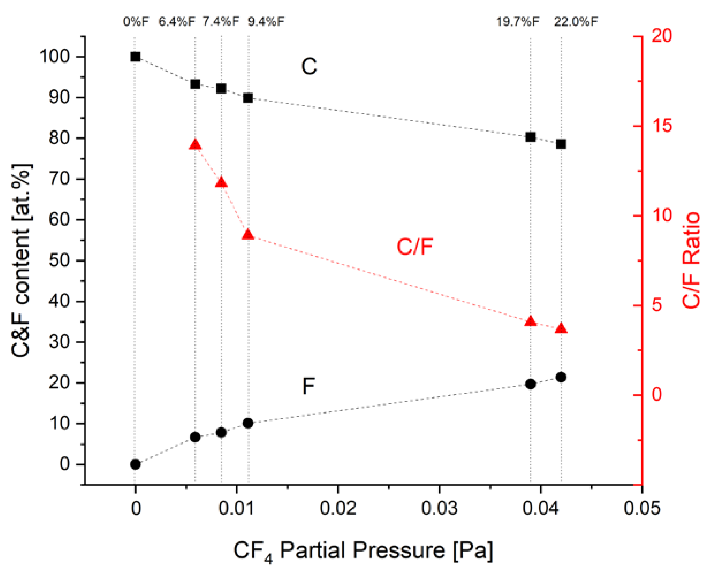
Figure 2.
Example of thickness measurements onto a cross-section of 6.4 %f coating.
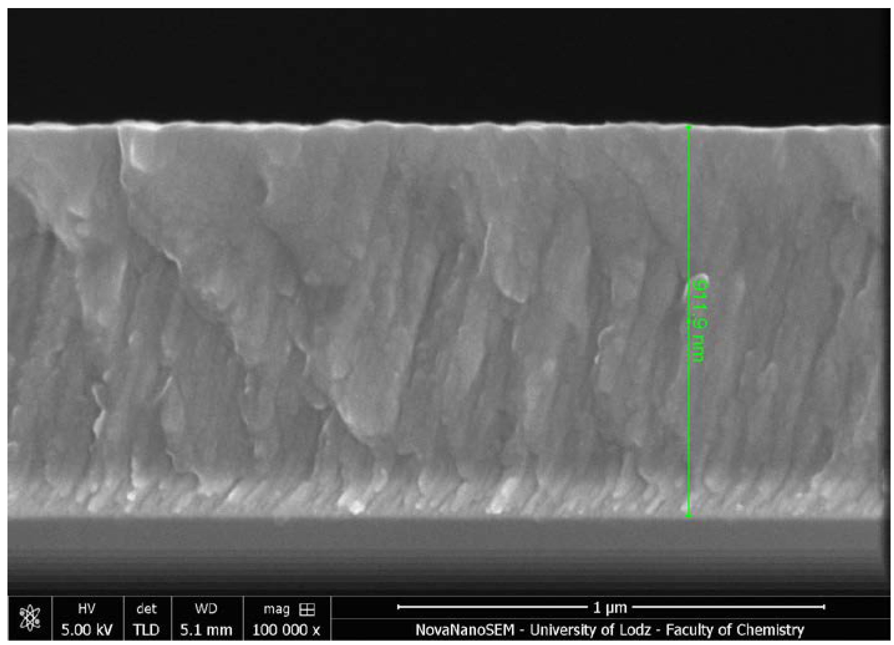
Figure 3.
Example of EDS linear distribution of chemical composition of the coating with low fluorine content (7.4 at.%). The inset shows lines for light elements (C, F, and N).
Figure 3.
Example of EDS linear distribution of chemical composition of the coating with low fluorine content (7.4 at.%). The inset shows lines for light elements (C, F, and N).
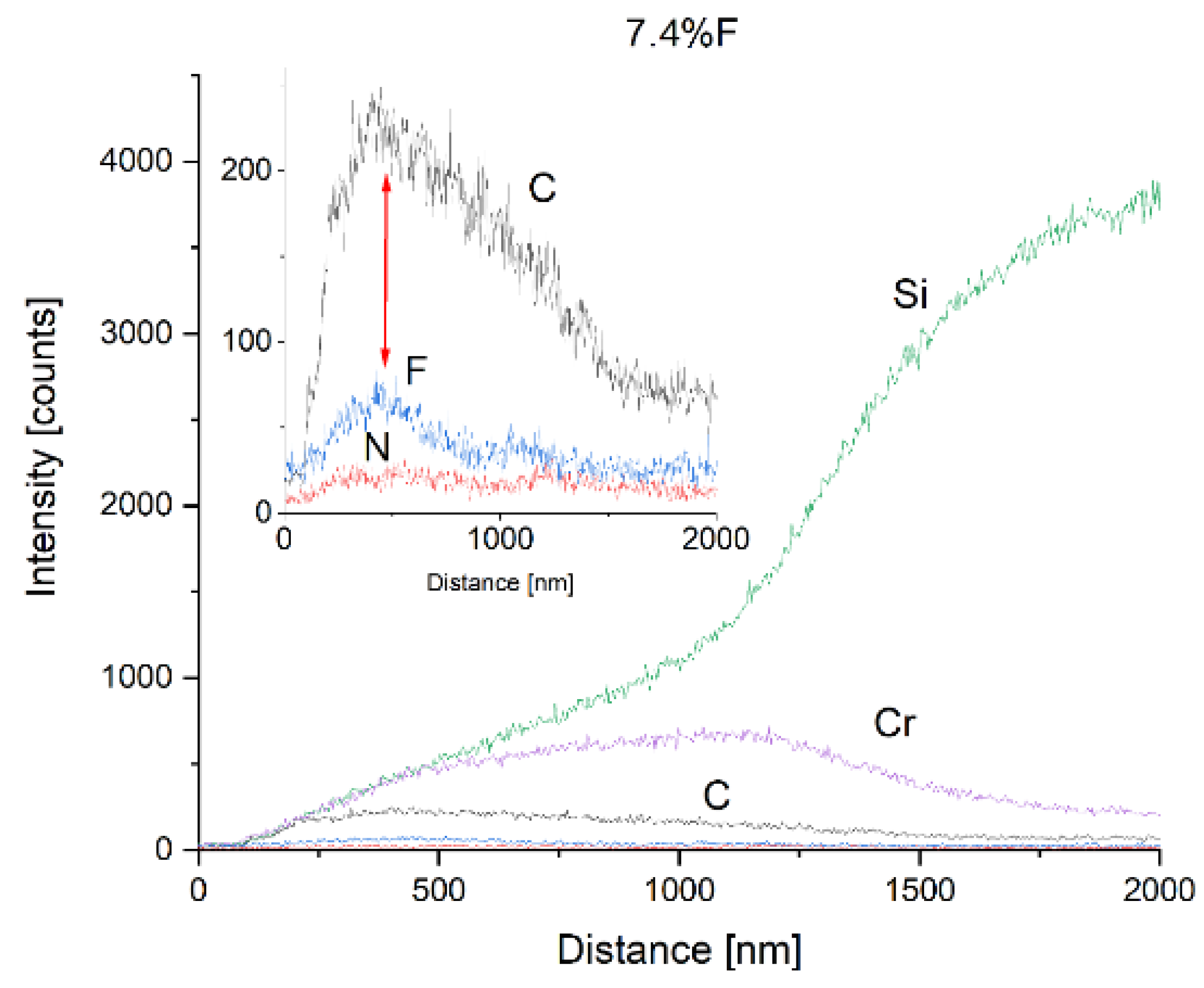
Figure 4.
Example of EDS linear distribution of chemical composition of the coating with high fluorine content (19.7 at.%). The inset shows lines for light elements (C, F, and N).
Figure 4.
Example of EDS linear distribution of chemical composition of the coating with high fluorine content (19.7 at.%). The inset shows lines for light elements (C, F, and N).
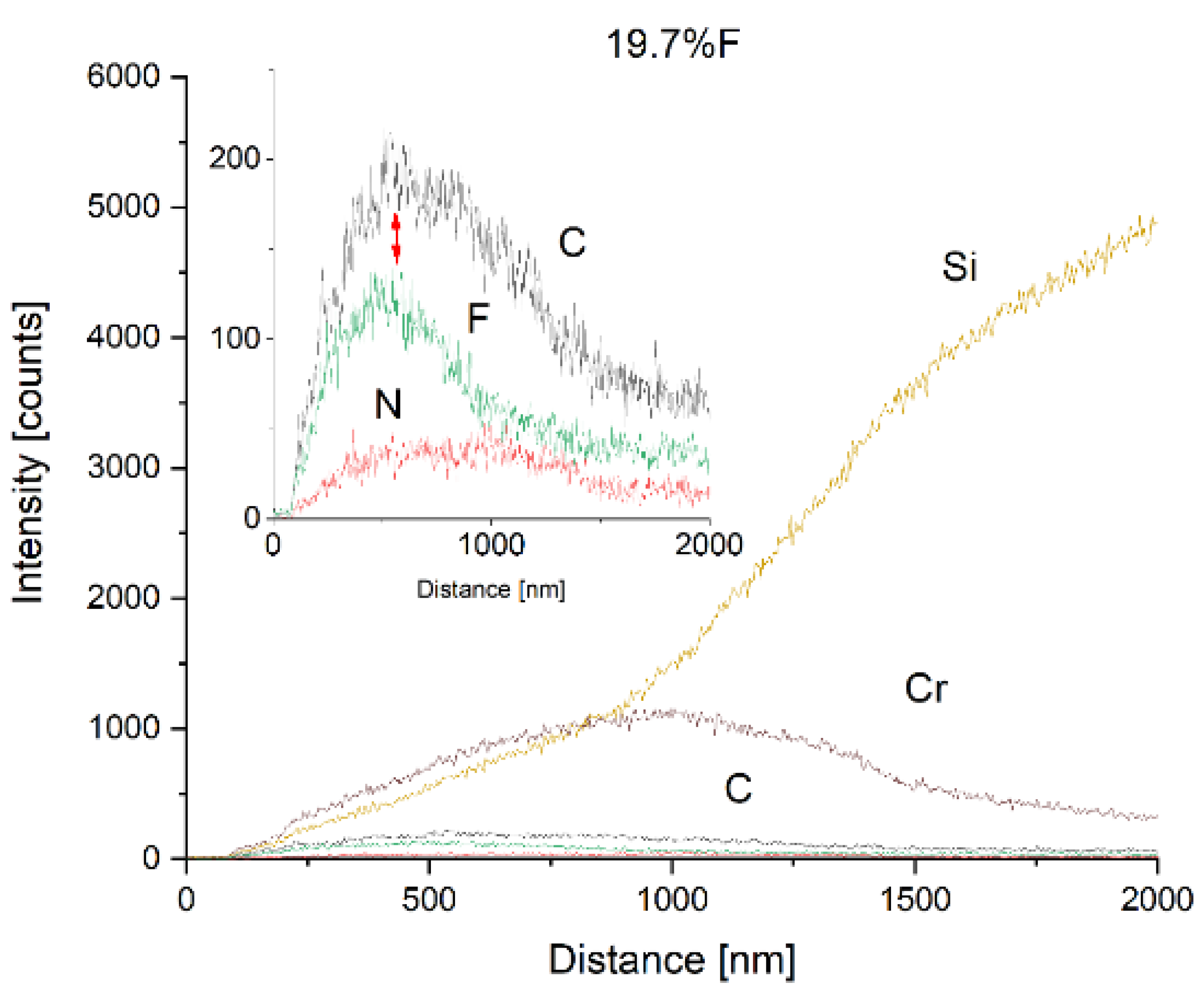
Figure 5.
Binding energy spectra from C 1s lines obtained by XPS.
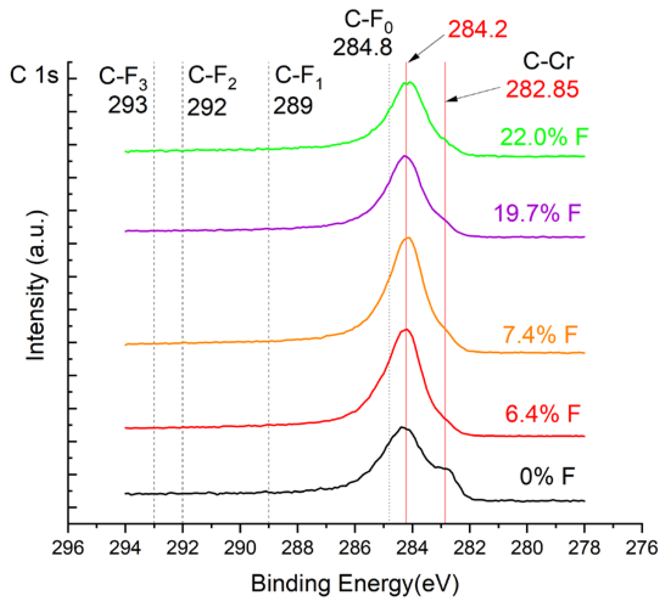
Figure 6.
Binding energy spectra from Cr 2p lines obtained by XPS.
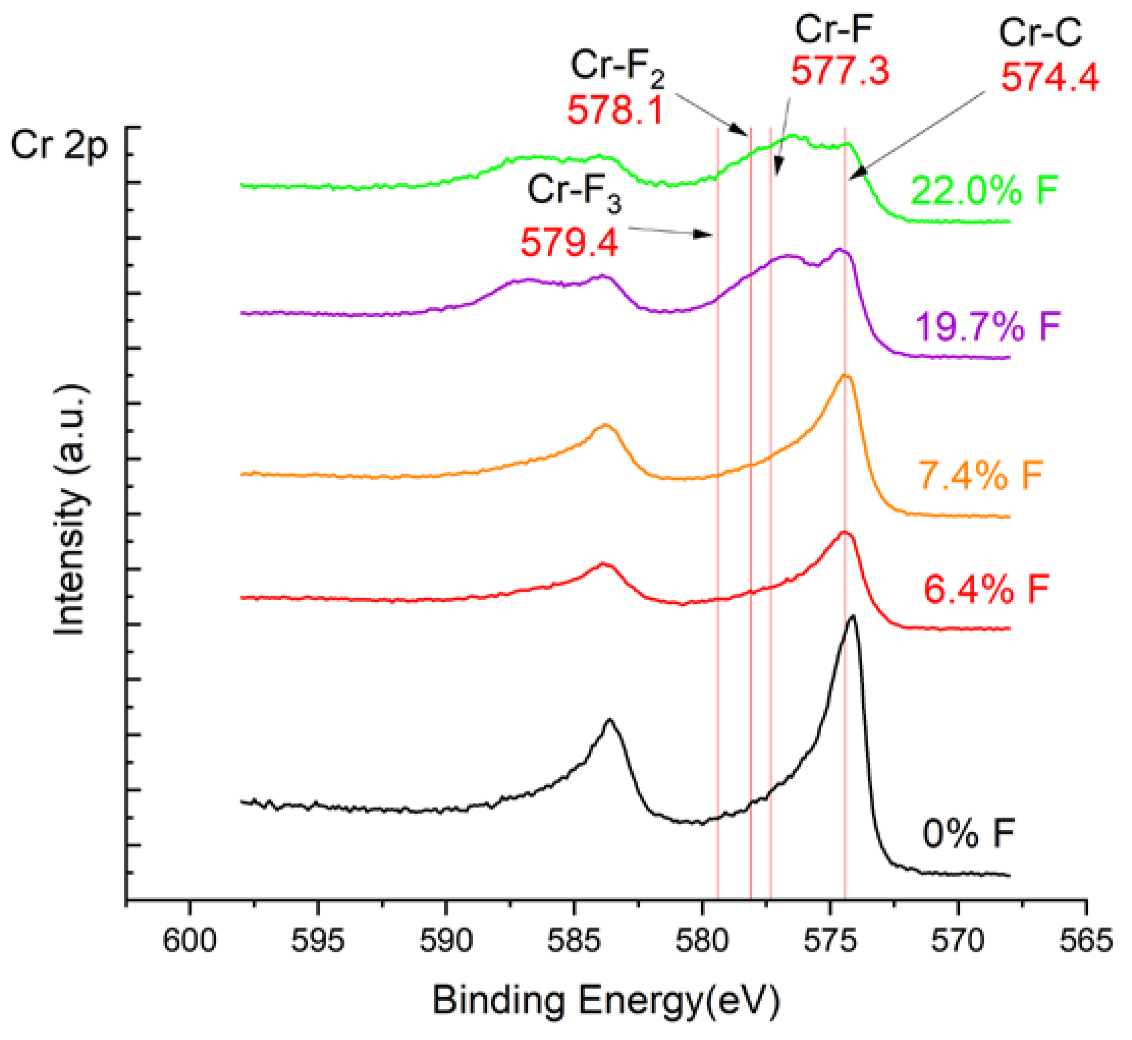
Figure 7.
Binding energy spectra from F 1s lines obtained by XPS.
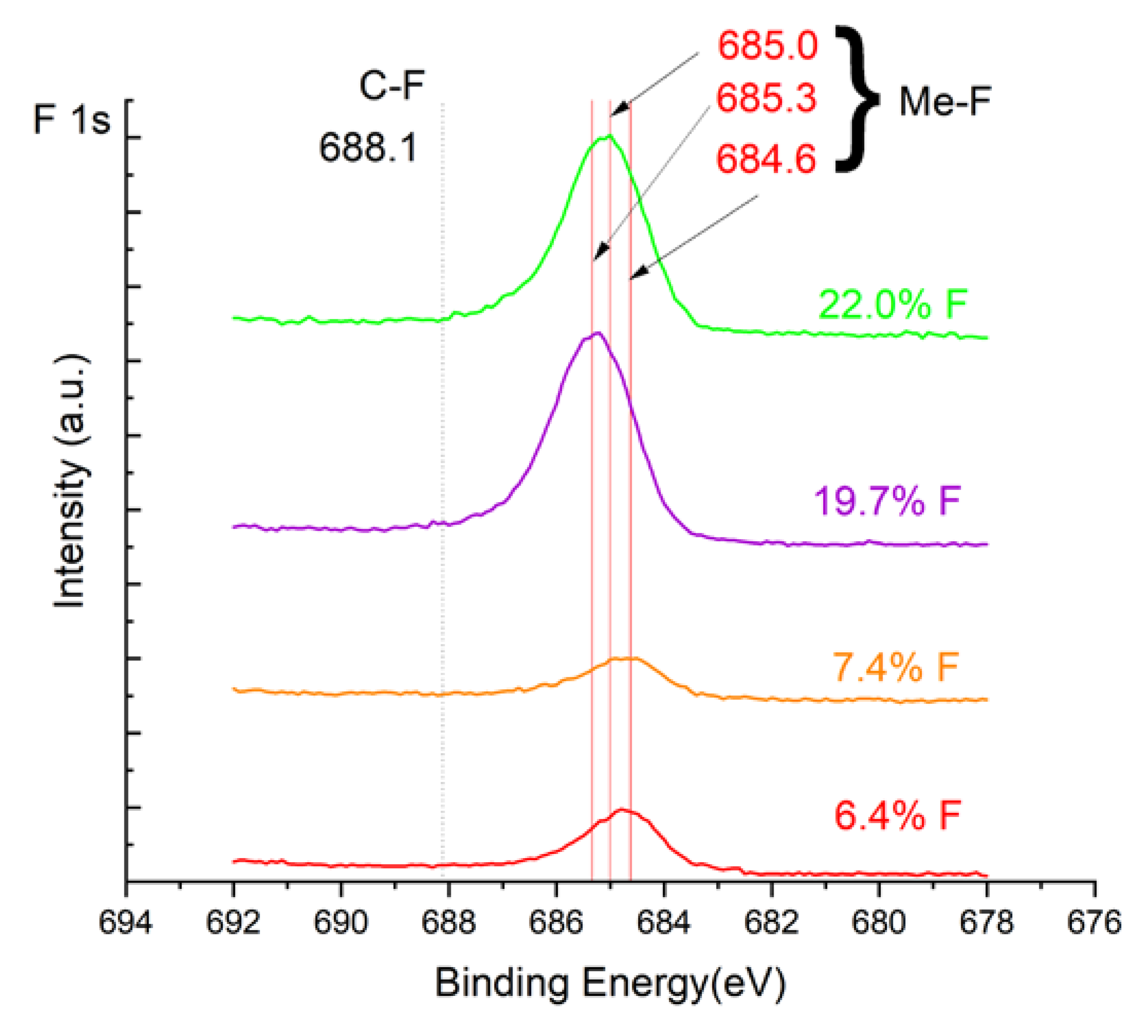
Figure 8.
Friction coefficients for investigated carbon-based nanocomposite nc-CrC/a-C: F coatings with different amounts of fluorine.
Figure 8.
Friction coefficients for investigated carbon-based nanocomposite nc-CrC/a-C: F coatings with different amounts of fluorine.
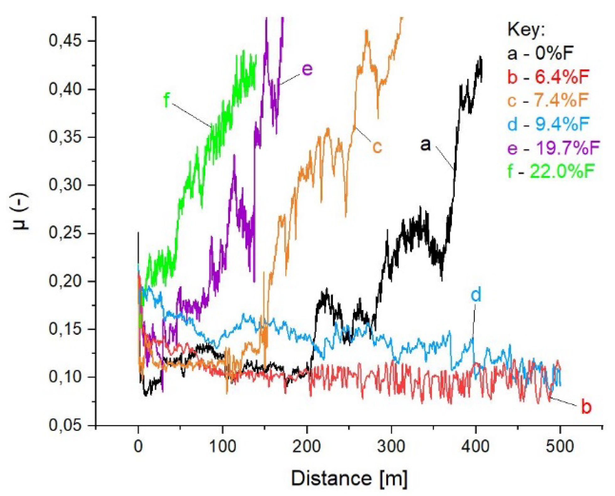
Figure 9.
0% F (a) and 6.4 %F (b) profiles of wear path from optical profilometry. Please,note the Z-axis scale change.
Figure 9.
0% F (a) and 6.4 %F (b) profiles of wear path from optical profilometry. Please,note the Z-axis scale change.
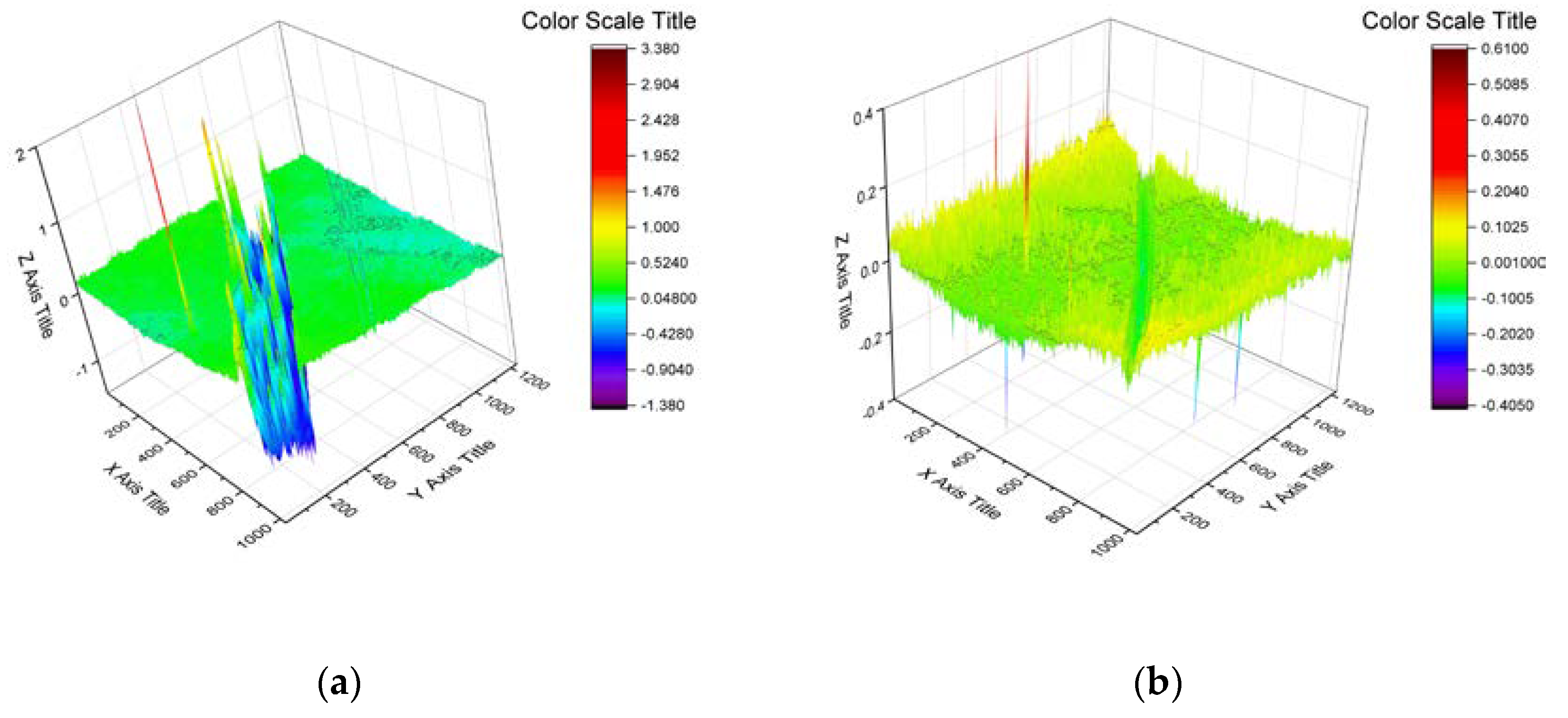
Figure 10.
Hardness (a) and elastic modulus (b) curves from continuous stiffness mode of nanoindentation.
Figure 10.
Hardness (a) and elastic modulus (b) curves from continuous stiffness mode of nanoindentation.
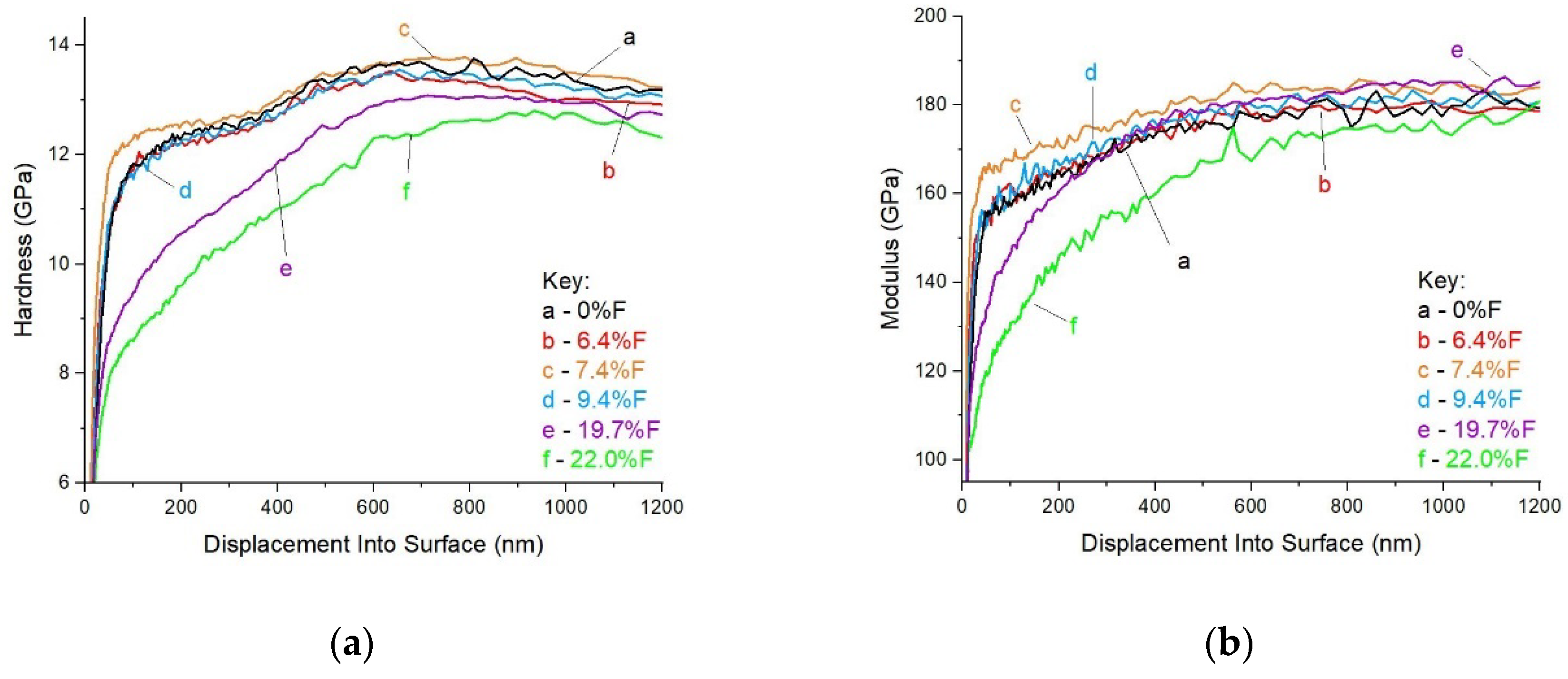

Table 1.
Deposition parameters of the coatings. Arrows show gradient change of the parameter within the time shown.
Table 1.
Deposition parameters of the coatings. Arrows show gradient change of the parameter within the time shown.
| Feature | Time | Cr | N2 | C | CF4 |
|---|---|---|---|---|---|
| Unit | [min] | [kW] | [sccm] | [kW] | [sccm] |
| STEP 1 | 0 → 5 | 0 → 1 | - | - | - |
| STEP 2 | 6 → 10 6 → 12* |
1 | 0 → 12.5 | - | - |
| STEP 3 | 11 → 20 13 → 22* |
1 | 12.5 | - | - |
| STEP 4 | 21 → 33 23 → 35* |
1 → 0.5 | 12.5 → 0 | 0 → 3 | - |
| STEP 5 | 34 → 103 36 → 62* |
0.5 | 0 | 3 | - |
| STEP 6 | 104 → 130 63 → 90* |
0.5 | 0 | 3 | 0 - 24 |
* - Deposition times of the 19.7% sample’s coating
Table 2.
Thickness and chemical composition of deposited nc-CrC/a-C: F coatings measured by EDS method.
Table 2.
Thickness and chemical composition of deposited nc-CrC/a-C: F coatings measured by EDS method.
| Sample | 0%F | 6.4%F | 7.4%F | 9.4%F | 19.7%F | 22.0%F |
|---|---|---|---|---|---|---|
| C | 84.4 | 78.5 | 74.3 | 74.6 | 60.5 | 62.4 |
| Cr | 13.1 | 14.7 | 17.9 | 15.6 | 18.9 | 14.9 |
| F | 0.0 | 6.4 | 7.4 | 9.4 | 19.7 | 22.0 |
| O | 1.8 | 0.4 | 0.4 | 0.4 | 0.9 | 0.8 |
|
Thickness [µm] ±0.1 |
0.9 | 1.0 | 0.9 | 0.9 | 0.9 | 1.1 |
Table 3.
Results obtained from the ‘pin-on-disc’ test.
|
Sample designation |
Coefficient of friction µ during the first 400 s | Lifespan of carbon coating | Kw | |
| /637 rotations | [m]/[rotations] | [mm3·N-1·m-1] | Std. Dev. | |
| 0%F | 0.10 | 202/3206 | 2.54×10⁻⁵ | 1×10⁻⁵ |
| 6.4%F | 0.14 | 500/7951 | 2.97×10⁻⁷ | 2×10⁻⁷ |
| 7.4%F | 0.12 | 143/2277 | 3.22×10⁻⁵ | 2×10⁻⁵ |
| 9.4%F | 0.18 | 500/7951 | 3.60×10⁻⁷ | 3×10⁻⁷ |
| 19.7%F | 0.14 | 45/714 | 7.84×10⁻⁵ | 2×10⁻⁵ |
| 22.0%F | 0.21 | 4/56 | 1.13×10⁻⁴ | 4×10⁻⁴ |
Disclaimer/Publisher’s Note: The statements, opinions and data contained in all publications are solely those of the individual author(s) and contributor(s) and not of MDPI and/or the editor(s). MDPI and/or the editor(s) disclaim responsibility for any injury to people or property resulting from any ideas, methods, instructions or products referred to in the content. |
© 2024 by the authors. Licensee MDPI, Basel, Switzerland. This article is an open access article distributed under the terms and conditions of the Creative Commons Attribution (CC BY) license (http://creativecommons.org/licenses/by/4.0/).
Copyright: This open access article is published under a Creative Commons CC BY 4.0 license, which permit the free download, distribution, and reuse, provided that the author and preprint are cited in any reuse.


