Submitted:
22 July 2024
Posted:
24 July 2024
You are already at the latest version
Abstract
In the future, smart cities will provide key services including seamless communication,
intelligent transport systems, advanced healthcare platforms, urban and infrastructure management,
and digital services for local and regional government. Therefore, a new service and networking
paradigm, called the Intelligent Edge Environment, has been specified. and is known as the Intelligent
Edge Environment. As a key part of this system, a new secure service ecosystem must be developed
to provide the secure realtime movement of services on different High-Performance Edge Cloud
Systems. This paper explores these issues by introducing the following mechanisms: the Resource
Allocation Algorithm, the Resource Allocation Secure Protocol and finally the Secure Service Protocols.
These systems were integrated into the Basic Capabilities System Library and a multithreaded FUSE
client connected to the Service Management Framework. Docker was used as a migration mechanism.
A prototype was developed and implemented using a FUSE-Network Memory System in which the
Network Memory Server was migrated as users move around. The result shows that this approach
was safe and could be used to develop new applications and services for smart cities.
Keywords:
Intelligent Edge Environment
; Secure Service Ecosystem
; Capabilities
; FUSE
; Docker
; SMART Ciities
1. Introduction
Smart cities leverage advanced technologies such as Mobile Edge Computing (MEC), Internet of Things (IoT), AI, and data analytics, fast communication networks, for example 5G/6G, to deliver efficient, sustainable, high-quality services, improving the overall quality of life for its citizens. These technologies can be combined to produce a new computing and service paradigm, called the Intelligent Edge Environment (IEE), in which services are run and managed from the edge of the network by default. The IEE Figure 1 is composed of following with these 7 layers, Heterogeneous layer, Data Management Layer, The High-Performance Edge Cloud System (HPSCS), Service Management Framework, Micro services Layer, Application Framework layer, Application Layer. The details of the IEE has been explored in [1].
1.1. Intelligent Edge Environment Layers
The functions of each layer of the IEE are detailed in Figure 2 :
- Layer 1: Heterogeneous Networking Layer (HNL): It integrates different types of wireless networks or technologies, providing connections using various technologies such as 4G, 5G, WIFI, and Cellular.
- Layer 2: Data Management Layer (DML): The layer has a crucial role in handling vast amounts of data generated by edge devices such Connected and Autonomous Vehicles (CAVs) and uses many structures such as blocks, files, databases, and Machine Learning (ML) to manage data.
- Layer 3: High-Performance Edge Cloud Systems (HPECS): This layer supports various cloud architectures and cloud types, including private, public, hybrid, and community clouds (AWS, Hadoop, etc.) using Virtual Machine (VMs) including VMware and Citrix ecosystems and Video Streaming, Augmented and Virtual Reality and Autonomous systems. Therefore, Resource Allocation Servers (RAS) are needed to manage various HPECS systems.
- Layer 4: Service Management Framework: This layer manages services and servers within the system. It offers mobile service support by migrating and replicating services using various migration techniques like Docker (containerization), KVM (virtualization), and Unikernels (specialized single-purpose virtual machines) to migrate services, using AI techniques to ensure that the service meets performance requirements.
- Layer 5: Microservices Layer (MSL): This layer supports for micro services and is the responsible for independently deployable services. These services should be fast and small in order to be easily migrated.
- Layer 6: Application Framework Layer (APL): This layer uses the microservices layer below to provide applications frameworks in order build applications for different environments such as Mobile Communications, Vehicular Networking, and IoT Smart Grids.
- Layer 7: Application Layer: This layer allows applications that have been built using the Application Framework Layer to be installed on the system and made available to users. Through this layer, users get applications that use all the resources of the IEE.
A key part of IEE is the development of a Secure Service Ecosystem (SSE) in which services can be dynamically moved securely between different commercial cloud systems. As shown in Figure 2, the SSE, therefore, encompasses the three core layers of the IEE which are the HPECS, SMF, and MSL layers. This paper explores how to build an SSE and the contributions of the work are detailed below.
- A new simple Resource Allocation Algorithm (RAA) is developed to run on a Resource Allocation Server (RAS). To enable mobile service, this algorithm has to be simple and fast.
- A new secure transfer protocol called the Resource Allocation Secure Protocol (RASP) is detailed. This will involve the use of cryptographic protocols such as ProVerif to show that the transfer protocol is safe.
- A secure access control system using capabilities, this is necessary to provide the Authentication, Authorization, Accounting (AAA).
- A new Secure Service Protocol is devolved using these mechanisms.
- The development of a new Service Management Framework (SMF) which can be used to manage applications and services in the IEE.
- The design of a capability-based Secure Service Protocol (SSP) to provide a complete framework for the IEE. The SSP is shown to be safe using Proverif.
- The implementation of a prototype SSP system using a Network Memory Server (NMS) to provide backing storage for a FUSE file system in a vehicular network.
The rest of the paper is organized as follows: Section 2 reviews the Related Work. Section 3 details the Simple Resource Allocation Algorithm, while Section 4 explores the RASP Protocol using ProVerif. In Section 5, a capability system discusses the structure in IEE, and in Section 6, the SSP Protocol is proposed and tested using ProVerif. Section 7 covers the prototype implementation. Finally, Section 8 concludes the paper.
2. Related Work
The convergence of the automotive industry with cognitive computing, forming the Industrial Cognitive Internet of Vehicles (CIoV), is a rapidly evolving field with significant implications for the QoS and security in vehicular networks. This convergence is driven by the increasing impact of social media on automotive services and the need for advanced edge computing solutions to reduce latency and enhance reliability. As explored by the author in [2], offloading cognitive computing tasks to the network edge using methods like CQP, which employs Canopy and K-medoids clustering along with a nondominated sorting genetic algorithm III, can optimize edge server (ES) quantification and placement, thereby improving QoS. In parallel, ensuring secure communications in IoT systems remains a critical challenge, particularly due to resource limitations that hinder the deployment of asymmetric cryptographic systems. The author in [3] proposes a lightweight key synchronization update algorithm for symmetric encryption schemes with pre-shared keys, which forms the basis of a new secure communication protocol. This protocol is resistant to common attacks and is verified using Tamarin, highlighting its practical viability in IoT environments. Resource contention in highly mobile environments, such as vehicular networks, further complicates QoS maintenance. As discussed by the authors in [4] and [5], traditional reactive handover techniques are inadequate, necessitating proactive approaches like Time Before Handover (TBH) and Network Dwell Time (NDT) to manage resources effectively through probabilistic mechanisms. The transformative impact of the Internet of Things (IoT) on global healthcare systems also underscores the necessity for secure and efficient data management at the edge of the Internet. The author in [6] highlights the integration of eHealth and mHealth mechanisms into national healthcare systems, proposing a new security framework that leverages blockchain technology to enhance healthcare security. This framework incorporates mechanisms such as Capabilities, Secure Remote Procedure Calls, and a Service Management Framework. Finally, the emergence of network storage as an alternative to large local storage systems in highly mobile environments presents unique challenges. The authors in [7] and [8], investigates the communication dynamics necessary for seamless connectivity and service migration, utilizing techniques like Docker, KVM, LXD, and Unikernels in vehicular edge environments. The authors [9] attempted to address the development of a secure commercial advertising scheme for Vehicular networks. They proposed a scheme name called “Business discovery (BUY)” that presents the concept of the beaconing market using a Vehicular network. The autors [10] have explored the use of high-performance computing and cloud resources for medical imaging, particularly focusing on microwave imaging for breast and brain scans. Space-time algorithms, while effective, face challenges due to their computational intensity. The authors [11] have observed, that among various vehicular applications, the most promising strategies involve the dissemination of commercial advertisements via car to RSU and car to car communication. The findings suggest that a proactive approach to service migration is essential for supporting network storage in these settings. Together, these studies illustrate the demand for innovative solutions to optimize QoS and ensure secure communications in the Intelligent edge environment for Smart cities.
3. The Simple Resource Algorithm
Resource management [12] is to the process of distributing available resources, such as CPU, Memory, Network and Storage, among various tasks in an efficient manner as it helps for delivering high performance in Cloud infrastructure to achieve high Quality of services (QoS) to deliver. Cloud systems use virtualization to replicate and share resources. Several algorithms are used to manage this allocation effectively. There are two types of resource algorithms, Static and Dynamic algorithms. However, when services are moved between Clouds, we must use dynamic algorithms which must be simple and fast because it is highly mobile environment. This algorithm is shown in Figure 3. The roles in the RAA are specified as follows:
- 1
- Advertising Cloud (CA, CB, CC...etc): Each Cloud Service Provider (CSP) has a finite set of resources available for servers and services. The cloud system broadcasts its available resources (CPU, memory, network, and storage) to the Receiving Servers.
- 2
- Receiving Servers (SA, SB, SC...etc): These servers can choose to migrate their services to the Advertising Clouds based on their hosting requirements.
- 3
- Resource Allocation Server (RAS): A trusted party responsible for verifying the resources of Advertising Clouds and the hosting requirements of Receiving Servers.

Table 1.
RAS Table
| Resource Allocation Server | Adverting Cloud (CA) | Adverting Cloud (CB) | Adverting Cloud (N) |
|---|---|---|---|
| Receiving Server (SA) | CPU, Memory, Network and storage | CPU, Memory, Network and Storage | CPU, Memory, Network and Storage |
| Receiving Server (SB) | CPU, Memory, Network and Storage | CPU, Memory, Network and Storage | CPU, Memory, Network and Storage |
| Receiving Server (N)1 | CPU, Memory, Network and Storage | CPU, Memory, Network and Storage | CPU, Memory, Network and Storage |
1 N-Number of Cloud servers.
The first stage of the RASP protocol uses the Resource Allocation Algorithm (RAA) for cloud advertisements. Each cloud system actively advertises its free resources in each round and uses mathematical formulations to determine if a service can be securely migrated to an advertising cloud (AC). The formulation below demonstrates how cloud CB advertises its resources and receiving server SA receives the requested resources.
3.1. Advertising Cloud Formulation
The variables indicate the number of CPUs, Memory, Storage, and Network resources respectively. These values help in determining the resource availability and allocation for secure service migration. At each round, each provider will use the mathematical formulation below: Step 1 of the RASP protocol and general notations is as follows:
-
Stage 1 1. CB → SA : Advc (CB, ResCB) ) [CB → SA: Advertising Cloud (CB) sends an advertisement (Advc) to the Receiving Servers (SA), detailing the free resources (Res freeCB)].
- -
- Maximum Resource of Cloud () = [CPU (Cmc), Memory (Cmm), Storage (Cms), Network (Cmn)],
- -
- Allocated Resource of Cloud () = [CPU (Cac), Memory (Cam), Storage (Cas), Network (Can)]and
- -
- Free Resource of Cloud () = [CPU (Cfc), Memory (Cfm), Storage (Cfs), Network (Cfn)]
| Algorithm 1 Cloud CB Formation |
|
Cloud CB Formation in detail,
- Step 1: The resources in consideration are categorized as CPU, Network, Memory, and Storage: Resources (r) include: CPU (c), Network (n), Memory (m), and Storage (s).
- Step 2-4: These steps define the maximum capacity for each type of resource (), current allocation of resources () and the available (unallocated) resources () in the AC.
- Step 5-10: Condition Check and Advertisement: The condition checks if there are any free resources (). If there are free resources, the AC sends an advertisement of these resources and waits for a response. If there are no free resources, the system waits until resources become available when () is greater than 0.
3.2. Receiving Servers Formulation
Receiving Servers (RS) receives an advertisement request from Advertising Cloud and its free resources. A server that needs to use a cloud has variables that detail its requirements. If the free resources of AC, Cfc,Cfm,Cfs,Cfn are larger than Receiving Server requirements, it can forward the request to the Resource Allocation Server (RAS) also refereed as the Registry (R). The requested resources of the server is given by (Req_Res of SA (SAreqr)). If we assume that, requested resources are of lesser capacity than free resources of AC and all requested resources must be true, then only it sends the request to RAS. Step 2 of the RASP protocol is as follows:
-
Stage 2 2.SA → R : (SA, CB, ResCB)pkR [SA → R: Receiving or Requested Servers (SA) sends an advertisement (Advc) to the Registry to verify the free resources (Res freeCB) and adding their identities].
- -
- Requested Resource of Server (Req_Res of SA ()) = {} CPU (Src), Memory (Srm), Storage (Sms), Network (Srn)]
| Algorithm 2 Server SA Formation |
|
[H]
|
Server SA Formation in detail,
- Step 1: The resources CPU, Networks, Memory, Storage are members of resources(r).
- Step 2-3: Server SAs Requested resources are declared. Inclusion of an element Req_Res to a set of SAreqr resources.
- Step 4-5: If Requested resources are greater than 0, the cloud services needs to find the next best fit server.
- Step 6-9 Condition check before resource Migration: It checks if the AC has sufficient free resources to meet the Receiving Server’s request. If sufficient resources are available and greater than 0, the request is accepted, and the details are sent to the RAS for verification and processing. Else ignore the advertisement.
3.3. Resource Allocation Server
The Resource Allocation Server (RAS) plays a crucial role in the resource allocation process. It is a trusted Party responsible for confirming the registration of cloud providers and certifying the capacity of their resources. The RAS ensures that only valid and adequately resourced clouds participate in service migrations. Function of RAS in the Algorithm:
- Registration and Certification: The RAS confirms the registration of cloud providers and certifies the capacity of resources available with the registered cloud providers.
- Request Verification: When a request for resources is received from a Receiving Server (SA), the RAS verifies the resources based on specific criteria before approving the migration.
Stage 2 of the RASP protocol therefore provides verification and certification. Once it receives the request from SA requested resources(SAreqr), the RAS verifies the resources based on the below Algorithm.
- Stage 2 3. R → SA: sign((CB, pkC, ResCB), pkS) [R → SA: The Registry approves the advertisement (Advc) and sends to the Receiving Servers (SA), detailing the free resources (Res freeCB) with its signature].
If the Registry receives the request from requested servers,
| Algorithm 3 RAS_CB |
|
Server RAS Formation in detail,
- Step 1-2 Verify Validity: The RAS server verifies whether it is a valid cloud and if Cloud resources are greater than the requested resources. If either condition false, then it rejects the request and updates CB that its an invalid server.
- Step 2-5 Pass Conditions: If the above conditions pass, then it sends an authenticated message to CB. This message confirms the approval of the resource migration.
| Algorithm 4 RAS_SA |
|
Server RAS Formation in detail,
- Step 1-2: RAS server verifies whether it is a valid server and if Cloud resources are greater than the requested resources which is not equalt 0 or not. If either conditions are false, then it rejects the request and updates SA that its an invalid Cloud.
- Step 2-5: If the above conditions pass, then it sends an authenticated message to SA.
The RAS is essential for ensuring the integrity and efficiency of resource allocation in cloud environments. It validates cloud providers, certifies their resources, and manages requests from Receiving Servers, ensuring only valid and adequately resourced clouds participate in service migrations. This multi-step verification process helps maintain a secure and reliable resource allocation framework.
4. RASP Protocol—An Overview
This abstract protocol has three roles: Server SA on Cloud CA, Cloud CB, and Registry. The Resource Allocation Security protocol (RASP) is broken into four stages. In the first stage, it uses the Resource Allocation Algorithm to manage cloud advertisements [13]. In addition, the proposed protocol was tested by ProVerif. The protocol has shown in Figure 4 as follows: Stage 1 corresponds to step 1 of the protocol; Stage 2 corresponds to steps 2-7; Stage 3 corresponds to 8-11, and finally, Stage 4 corresponds to step 12. The RASP protocol is followed in exactly the same way an outlined below and shows the steps for Cloud-to-Cloud migration of services.
4.1. General Notations
Table tab2 shows the parameters used in the RASP protocol.
Table 2.
RASP Table
| Notation | Explanation |
|---|---|
| CA, CB, SA and SB | Cloud and Server Identities |
| pkC/skC, pkS/skS, pkR/skR | public and private key pairs of Cloud CB, server SA & Registry |
| M_Reqc, M_Trfs, M_Ackc | Request for migration, trannsfers and acknowledgement |
| sign | Signature/signed by the Registry |
| aenc | Asymmetric Encryption |
| enc | Symmetric Encryption |
| Ksc | Symmetric session key |
| Ns, Nc | Nonce of SA and CB |
| ResSA | Requested Resources of SA & CB |
- 1
-
Stage1: Advertisement:Cloud CB actively advertises its resources Server SA receives advertisements from Cloud CB advertising Cloud Bs resources with its identity CB.1. CB → SA : Advc (CB, ResCB)
- 2
-
Stage2: Authentication of SA and CB as well as migration request and response:Server SA first requests the RAS/Registry to authenticate Cloud CB and its resources. In Step 3, the Registry (R) authenticates Server SA. In Step 4, Server SA sends a migration request to Cloud CB. In Step 5, Cloud CB sends a request to the Registry to verify that Server SA’s request for resources is valid. In Step 6, the Registry replies to Cloud CB. In Step 7, Cloud CB sends the migration response back to Server SA.2. SA → R : (SA, CB, ResCB)pkR3. R → SA : sign((CB, pkC, ResCB), pkS)4. SA → CB : aenc ((Ns, SA , ResSA), pkC)5. CB → R : (CB, SA , ResSA)pkR6. R → CB : sign((SA, pkS , ResSA), pkC)7. CB → SA : aenc((Ns, Nc, CB), pkS)
- 3
-
Stage3: Migration transfer:In Step 8, Server SA generates the session key (Ksc) to start the migration request. In Step 9, Cloud CB sends the migration initialization request. In Step 10, Server SA performs the migration transfer. In Step 11, Cloud CB sends an acknowledgment to Server SA. In Step 12, the service on Cloud CB (SB) updates the Registry on its new location.8. SA → CB : aenc((Nc, Ksc), pkC)9. CB → SA : enc ((M_Reqc, SA), Ksc)10. SA → CB : enc ((M_Trfs, ResSA), Ksc)11. CB → SA : enc ((M_Ackc), Ksc)
- 4
-
Stage4: Update of New service location to the Registry:The new service SB is now running on Cloud CB and informs the Registry that it has been successfully migrated.12. SB → R : aenc((SB, CB), pkR)
4.2. ProVerif an Overview
ProVerif [14] is a formal verification and highly automated tool used for analyzing the security properties of cryptographic protocols. It employs applied calculus to model concurrent systems and their interactions. The tool comprehends the protocol’s abstraction, including how messages are exchanged between parties and the use of cryptographic primitives such as encryption, decryption, and signatures. ProVerif verifies the service migration mechanism’s secrecy, authentication, and key exchange. Another strength of this tool is that it performs symbolic analysis instead of concrete analysis, aiding in understanding attack scenarios. ProVerif provides attack traces [15] if it finds any violations of a security property.
The output of the Query attacker() query function results as "True", indicating that the security property cannot be accessed by the attacker. This validates the attacker’s lack of knowledge and ensures the secrecy of data authentication between parties or multiple roles for securely transferring data and authenticated communications across an unlimited number of sessions using unbounded data. If the outcome of the attacker() function is "False", the security property value is accessible to the attacker. Finally, the result displays any attack trace and indicates whether the attacker() query returns TRUE or FALSE.
4.2.1. ProVerif Results
The results show that RASP can preserve the secrecy, authentication and key exchange of the service migration mechanism.
- Nonces are secured and not derived by the attacker: specific nonces (SNs, SNc, CNs, CNc) used in the protocol are not derivable by an attacker, ensuring their confidentiality. Each line indicates that the respective nonce cannot be compromised (is true).
- session key Results confirms that the session key (Ksc) and associated bitstrings (SNk, CNk) are secure from the attacker. The line "RESULT not attacker_bitstring (SNk []) is true." with Ksc also specifies the conditions under which this key is secure.
- Private keys Results confirms that the session key (Ksc) and associated bitstrings (SNk, CNk) are secure from the attacker. The line "RESULT not attacker_bitstring (SNk []) is true." with Ksc also specifies the conditions under which this key is secure.
- AuthenticationIt validates the mutual authentication between SA and CB. The use of inj-event indicates that the protocol verifies injective correspondence, meaning each event endSparam (or endCparam) has a matching beginSparam (or beginCparam), ensuring that both parties authenticate each other correctly.
Table 3.
Query attacker ()
| Security properties | Server SA event | Cloud CB event |
|---|---|---|
| Session key | True | True |
| Private keys | True | True |
| Nonces | True | True |
| Event begin | True | True |
| Requested resources | True | - |
| Advc Resources | - | False |
1 Query attacker of results
By using symmetric session key (Ksc), the requested service is transferred to the new location CB. This research explored the development of a new resource allocation and secure service migration framework that encompasses the computing resources to migrate in cloud environments.
5. Capabilities
Capabilities are critical for system security, providing a robust mechanism for access control through unforgeable tokens. It plays a crucial role in identifying objects and their properties within a system. It is essential to manage and protect these capabilities diligently to prevent unauthorized generation or alteration. Proper management is vital to maintaining system integrity and security, ensuring that only authorized users can access specific objects and perform actions according to their assigned capabilities. This careful oversight helps safeguard the system against potential security breaches and misuse. Data structure: it contains two pieces of data and functionality.
- Unique Object Identification and Access Rights
- Functionality: Capabilities can provide Role-Based Access Control (RBAC) access for users. Some capabilities are not directly assigned to users; instead, they are assigned to roles, and roles are then assigned to users. These are known as role-based capabilities.
- Role Assignment: Capabilities can be assigned to roles. Roles are then assigned to users. This structure supports RBAC, ensuring that users have access based on their roles within an organization.
- IPv6 Address Space and Capability ID System: Utilizes a modified Location/ID split based on the work of [16]. Enables the creation of a capability ID-based system for people, applications, and cloud infrastructure.
5.1. Capabilities in IEE
Intelligent Edge Environment (IEE) capabilities are crucial for secure and efficient access control. By utilizing role-based capabilities and advanced addressing systems like IPv6, IEE can ensure robust access management and resource allocation while maintaining high levels of security and integrity. IEE is a dynamic environment where security challenges are significantly higher than those in traditional computing environments. Traditional AAA (Authentication, Authorization, and Accounting) mechanisms, such as using RADIUS servers, are no longer effective solutions in this context. Given the scalability requirements of large systems, it was decided that AAA should be based on the subject or user rather than the object. This approach is more scalable and suitable for modern, complex environments. Consequently, capabilities are used to provide AAA for the IEE, ensuring that security and access control mechanisms are effective and adaptable to the unique demands of edge computing [17].
5.1.1. Capabilities Structure
In Intelligent Edge Environment (IEE), every object and its properties are identified using capabilities. These capabilities must be carefully managed and protected to prevent unauthorized creation or modification, and they should be easily revocable. The format of the capability-based system is shown in Figure 5, and its structure is explained below.
- Type Field (8 bits): This field specifies the type of object capability being used, such as users, digital assets, facilities, etc.
- SYS Field (4 bits): This field helps manage capabilities. The four bits within the SYS field are explained below.
- Property Field (12 bits): This field defines the properties of the object associated with the capability. It relates to the properties or functions of the object that the capability refers to.
- Object ID (72 bits): This field uniquely identifies the object in the system. It includes a EUI-64 identification field to identify the object and an 8-bit netadmin field to manage the object on a network.
- Random Bit Field (16 bits): Provides unforgeability and helps uniquely identify the object. This field is generated after the type field, SYS field, property field, and Object ID field are created. When proxy certificates are created, a new random field is generated. This field also allows for easy revocation of capabilities by simply changing the random field and recomputing the capability, hence revoking previous versions.
- Hash Field (16 bits): Detects tampering of capabilities. When a capability is created, the type field, SYS field, property field, and Object ID field are first generated, followed by the random bit field. These fields are then used to generate a SHA-1 hash, which is placed in the Hash Field of the capability.
As shown in Figure 6, the SYS field consists of the following bits:
- Private or P bit: Restricts the list of people holding the capability. With a public capability, only the capability for the object must be presented, allowing anyone to hold it without needing the identification of the subject, the person holding the capability. With a private capability, both the object’s capability and the subject or user’s capability must be presented to ensure the sender has the right to invoke the object.
- System or S bit: Indicates whether the object involved was created by the system or by an application or user. A system capability cannot be modified or deleted by users or applications.
- Master or M bit: Indicates that the capability was created by a Certificate Authority (CA). The master capability is usually created when the object is created. If this bit is not set, it means this is a proxy capability. Proxy capabilities are derived from master capabilities and cannot be derived from other proxy capabilities.
- Change or C bit: Indicates whether this capability can be changed. If this bit is set, proxy capabilities can be derived from the master capability. If this bit is not set, the capability cannot be modified, and proxy capabilities cannot be generated.
By adhering to these principles, Intelligent Edge Environments can maintain a high level of security and efficiency, ensuring that resources are managed effectively and that unauthorized access is prevented.
6. The Secure Service Protocol (SSP)
The advancement of highly mobile technologies such as Vehicular Adhoc Networks (VANETs), MEC, AI, and the IoT requires multiple interfaces to seamlessly connect and provide optimal performance for mobile users. As discussed in the Introduction, MEC facilitates moving services closer, minimizing the need for data processing on remote servers, reducing delays, and increasing network bandwidth. It is essential to enable service migration to support these networks, allowing services to migrate as mobile users move around. Figure 7 for a visual representation of the new environment.
Due to the need for a robust service architecture, a new service management framework for mobile clouds has been developed, as shown in Figure 8 and detailed in [18].
6.1. SMP Layers in Detail
- The Application Layer (AL) is the first layer of SMF. It runs on the mobile node and calls the service through the Service Management Layer (SManL). AL provides the service name, Service ID, and required QoS. When a service first comes to the SMF, it should have a unique ID for identification. The service name indicates the type of service being provided, such as CPU, Memory, or Storage. Lastly, the Application Layer must define QoS parameters for the required service, such as delay time, latency, bandwidth, reliability, and security.
- The Service Management Layer (SManL) is responsible for administering the mobile service, managing service subscriptions, and overseeing service delivery for the layers below it. Service subscription includes managing Service-Level Agreements (SLAs) and billing. Service delivery entails determining how services should move from one location to another. When this layer determines that a service should be migrated, it forwards this information to the service migration layer (SML).
- The Service Migration Layer (SML) manages migration requests from SManL and employs a Resource Allocation Security Protocol (RASP) to securely execute the migration process. Upon completion, SML informs SManL. The RASP, as described by [19], utilizes standard migration mechanisms like Docker, KVM, LXD, and Unikernels for the actual migration.
- Service Connection Layer (SCL): This layer monitors how clients connect to the services between the mobile node and the server. It reports to the SManL when the mobile node is no longer available due to handover to another network.
6.2. SSP Protocol—An overview
Capabilities can be flexibly used to provide AAA in many environments. Furthermore, by combining capabilities, SMF, and RASP techniques, it is possible to design a Secure Service Protocol (SSP) that can protect any service. The SSP protocol has been developed to ensure that the proposed service protocol is secure and can be applied to any service. It is broken down into five stages to clarify the necessary operations in secure service migration. The interaction between an application, the Service Management Framework (SMF), and services supported by the SMF are shown in Table 4 and Figure 9. The SSP protocol is defined in the same way as the RASP protocol outlined.
-
Stage 1: Registration of the Service with the SMF: In Stage 1, the Cloud Management System (CMS) registers the Service with the SMF. This involves providing a list of servers and their public keys that will be running the Service. After this, in step 2, the SMF registers the Service and returns the Service ID (SERV ID) and the Service Capability (SERV CAP). Following this, the CMS initiates the servers to implement the Service on different machines and passes the Service ID and the Service Capability.
- 1
- CMS → SMF: (Register Service (Service Details), (PK(SMF)))
- 2
- SMF → CMS: (Service Registered (Service Details, SERV ID, SERV CAP), (PK(CMS)))
-
Stage 2: The Application interacts with the SMF to get a server that implements the Service: In Stage 2, the Application interacts with the SMF to obtain a server that provides the Service. To utilize a service, an application must request the SMF to locate a suitable server. In step 3, the Application provides the Device Capability (DEV CAP), User Capability (USER CAP), Service Name, Service Version, and the Application’s public key running on the machine. In step 4, the SMF selects a server for that Service and contacts it using its public key, passing the Client’s DEV CAP, USER CAP, and IP address. In the subsequent step, the Chosen Server accepts the request. It generates a timed capability from the service capability, which expires in 60 seconds if the Application does not connect to the server. This SERV TIME CAP is a private proxy capability derived from the Service Capability and cannot be altered; only the USER CAP and DEV CAP can utilize the capability. The Chosen Server also provides its IP address and the TCP port of the Service using the public key of the SMF. In the final step of Stage 2, the SMF returns to the Application with DEV CAP, USER CAP, timed capability, the Server’s IP address, Service Port number, and public keys of the Chosen Server, enabling the Application to connect to the server.
- 3
- APPL→ SMF: (Request service (Service Name, Service Version, DEV CAP, USER CAP, PK(APPL)), (PK(SMF))
- 4
- SMF Chosen ->Server: (Usage request (DEV CAP, USER CAP, IP Client),(PK(SERV))).
- 5
- Chosen Server-> SMF : SMF (Usage request accepted (DEV CAP, USER CAP, SERV TIME CAP, IP Server, Port Server), (PK(SMF)))
- 6
- SMF→ APPL: (Request service accepted (DEV CAP, USER CAP, SERV TIME CAP, IP Server, Port Server, PK(SERV)), (PK(APPL)))
-
Stage 3: The Application sets up a secure session with the Server. During Stage 3, the Application initiates a secure session with the Server by sending a session start request. This request includes the DEV CAP (device capability), USER CAP (user capability), SERV ID (server ID), a unique random number called Nonce of A (NA), the Server’s public key, and the SERV TIME CAP (server time capability). Nonce (NA) ensures that the session is unique on the Application side. In response, the Server sends back a session capability (CAP SESS), DEV CAP, USER CAP, NA, NB (another unique random number for the Server side), and a session key (SESS KEY). The SESS KEY is a symmetric key used only once to encrypt the details in one communication session.
- 7
- APPL → Chosen Server: (Session Start Request (DEV CAP, USER CAP, SERV ID, SERV TIME CAP, NA)), (PK(SERV)).
- 8
- Chosen Server→ APPL : (Session Start Request Accepted DEV CAP, USER CAP, CAP SESS, SESS KEY, NA, NB), (PK(APPL)).
-
Stage 4: The Application gets service by using the CAP SESS key and encrypts using the SESS KEY In Stage 4 of the process, the application uses the CAP SESS key to access a service and encrypts data using the SESS KEY. The application sends a service request to the chosen server with the CAP SESS, Nonce (NB), and uses the SESS KEY. The server responds by sending CAP SESS, NA, and detailed results using the SESS KEY. NA ensures that the session is unique on the application side.
- 9
- APPL → Chosen Server : (Service Request (CAP SESS, NB, Request Details)(SESS KEY))
- 10
- Chosen Server → APPL: (Service Request Done (CAP SESS, NA, Result Details) (SESS KEY))
-
Stage 5: The Application is finished and terminates the session In Stage 5, the application terminates the session by sending end requests to the chosen server with CAP SESS, nonce (NB), and session end using the session key. The server then terminates the session and revokes the CAP SESS capability to prevent replay attacks.
- 11
- APPL → Chosen Server :(Session End Request Accepted (CAP SESS, Nonce (A), Session End)(SESS KEY)).
6.3. ProVerif results
The SSP protocol is designed using the ProVerif tool, and it results as "safe". In Stage 4, the application gets service by using the capability session key and encrypts using the Session key to the Chosen server. The query attacker of function to “Session key” (Ksappl) is TRUE.
The private keys of Cloud Management System (CMS), Service Management Framework (SMF), Application (Appl), and Chosen Server(S) results as True. In Stage 3 and Stage 4, Nonces are used between the chosen Server and the Application to prevent replay attacks. The output of Nonce is “True” from Server sessions. The Cloud Management System (CMS), which supports a number of services, contacts the SMF to register the Service. We applied the “event begin and end function” to verify whether the sessions started before the SMF started or not, and it results as “True”. In the same way, the and-begin and end functions are used to verify from Server Sessions.
6.4. Queries for Private Keys
Queries for Private keys of Application, Cloud Management System, Service Management Framework and Server :query attacker(sksmf); query attacker(skcms); query attacker(skappl); query attacker(skS);
- RESULT not attacker_skey(sksmf[]) is true.
- RESULT not attacker_skey(skcms[]) is true.
- RESULT not attacker_skey(skappl[]) is true.
- RESULT not attacker_skey(skS[]) is true.
6.4.1. Queries for Nonces
Queries for nonce between Server and application: query attacker(SERVERNA); attacker(SERVERNB); attacker(APPLNB); attacker(APPLNA):
- RESULT not attacker_bitstring_(SERVERNA[]) is true.
- RESULT not attacker_bitstring_(SERVERNB[]) is true.
6.4.2. Queries for Symmetric Key
Queries for Symmetric key : query attacker(Ksappl); query attacker(SERVERk)
- RESULT not attacker_key (Ksappl[m7 = v_10131,m4 = v_10132,!1 = v_10133]) is true.
- RESULT not attacker_bitstring (SERVERk[ []) is true.
6.4.3. Queries for authentication of Server event and CMS event
Queries for Symmetric key : query attacker(Ksappl); query attacker(SERVERk)
-
RESULT inj-event(endSERVERparam(x_24696)) →inj-event(beginSERVERparam(x_24696)) is true.
-
RESULT inj-event(endCMSparam(x_38772)) →inj-event(beginCMSparam(x_38772)) is true.
-
RESULT event(endCMSparam(x_42655)) →event(beginCMSparam(x_42655)) is true.
7. Prototype Implementation
Using new mechanisms such as Capabilities, and a new Service Management Framework, this research has proposed a new Secure Service Protocol, which can be used to protect any service. The protocol has been verified using ProVerif. In this section, we explore the building of prototype system.
7.1. Basic capability System Library(BCSL)
We developed our prototype system using the Basic Capability System Library (BCSL) as our foundation. This library, depicted in Figure 11, is part of the Base Layer of the Implementation Framework. It supports users, devices, and services and allows servers to be added to the services. Each component has its capability, which is used to access other objects, such as files. Services are created and registered with the Service Management Layer (SML). The middle layer is responsible for enhancement, tuning, mapping layers, and updates. The Basic Capability System Library, created by the ALERT Team of Middlesex University London, is a primary system that makes users, devices, services, and servers and implements them. These types are identified as CAP USER, CAP DEVICE, and CAP SERVICE as their Capability types, respectively. The top layer focuses on system implementation. In this layer, our primary goal is to improve the Service Management Framework (SMF) so that it can securely replicate and migrate services. Our work primarily centres on securely migrating and replicating registered services.
7.2. Make Fuxfs Multithreaded
The FUSE and NMS servers store and manage the system’s data. NMS provides networked block storage. When a client moves to another network, the NMS is migrated to the new network to improve performance. In this scenario, the client is referred to as "fuxfs," and the server is called "fuxfs server", and they communicate using normal communication protocols.
7.3. Fuxfs Server
The NMS server is a simple program: so should be easy to migrate between networks. This NMS server is working with the FUSE system. The header file for this program is named "fuxf.h" and executable code is in "Fuxfs_server". To compile and run the Fuse server.
- Compile command: gcc -o Fuxfs_server Fuxfs_server.c
- Run command: ./Fuxfs_server 0.0.0.0
7.4. Fuxfs Client
This is the client side of the FUSE code.
- Compile command: gcc -Wall fuxfsmg.c `pkg-config fuse –cflags –libs` -o fuxfs -w -L./ libcapab.a -lpthread
- Run command: ./Fuxfs /tmp/fuse 0.0.0.0
7.5. Make Fuxfs Multithreaded
In order to develop the prototype, it was decided to make the client (i.e the fuxfs) multithreaded. One thread called SMF_THREAD managed the interaction with the SMF as shown in Figure 12.
7.6. Multithread - SMF Commands
The SMF was developed to manage services and migrate and replicate services in a secure environment. To check the secure migration on Service Management Framework (SMF), we developed C programs on the Ubuntu 20.04 platform. We used a private Docker [20] repository to migrate our service and tested them in our local environment. The SMF provides the following functions.
- Register Service: The function allows the service to be registered with the SMF. It collects information on the service, including the service name, the description of the service, the version of the service (i.e., 0 is the latest version), the TCP/UDP port number, and the service capability. Once the service has been successfully registered with the SMF, the SMF generates the global_id. The local_id is generated by the client.
- Register User: This function helps the new user register with the SMF. It collects information about the user, including the first name, surname, role, rank, and specialist, as well as the capability of the user to register. Once the user has been successfully registered with the SMF, the SMF will generate their global user ID. Each device will have a unique local device ID (generated by the SMF_THREAD) and a global device ID (generated by the SMF).
- Register Device: This register device function allows the devices to register with SMF. To register a device, the name of the device, the first name and surname of the device owner, and the device capability are also collected once the device is registered. Each device will have a unique local device ID and a global device ID.
- Add Server: This function helps the server be added to the required service. It also collects details about the server, including the server global ID given by NMS, the server’s name, the server location using the IPv4 address, and the server’s maximum load.
- Request Service : Once a service is registers with the SMF, the service can be requested by users who want to use it. Servers should provide this service to the requested applications. This function allows an application to request service. After the application sends a service request to SManL, SManL will provide the necessary parameters for the application to contact the server that runs the requested service.
- Migrate Service: This function allows the services to migrate to the required servers. It also collects details about the global service ID, the global user_id, and the global device_id and will set up the migration using Docker container technology. Once the migration is successful, a successful result will be returned to the caller.
7.7. NMS Part of FUSE as a Service
We want to use the framework to implement microservices in vehicular environments. Microservices are faster to migrate and hence can be used to maintain QoS in these networks. As our first use case, we will consider a FUSE file system that is a user space file system commonly employed in Linux OS. The setup which is shown in Figure 13, provides a storage platform for mobile users with then NMS provide block network storage to FUSE clients which run on mobile phones. If a mobile user moves to another network then the NMS is migrated in order to achieve better performance. In order to test the Service Management Framework, NMS will be migrated from one cloud server to another. In our paper, we have shown that by implementing a FUSE file system in Docker’s private repository and using it at a new location. We installed Docker on a Linux Ubuntu 20.04 machine and set up a private repository to store our services. This allows us to use computing resources for migrating to cloud environments.
7.8. SMF - NMS as a Service
We utilized the framework for implementing micro services in vehicular environments. It is quick to migrate and can, therefore, help maintain QoS in these networks. For our initial use case, we focused on a FUSE file system, which is a user-space file system commonly used in the Linux OS. To test the Service Management Framework, the NMS service will be migrated from one cloud server to another. In this paper, we demonstrate the implementation of a FUSE file system in Docker’s private repository and its use in a new location’s location.
The prototype SMF supports the following functions: Register the service, register the user, register the device, add a server, request and migrate the service. SMF was used successfully start the framework. Then, the FUSE client was started and connected to the SMF. The Fuxfs_server was compiled and connected to the SMF while the client was connected using the FUXFS SMF Multithread. The "Migrate service" uses a Docker container from one location to another to migrate the NMS service. Figure 14 shows the FUSE running container status from the Docker hub name and private repository and the NMS service successfully.
8. Conclusions and Future work
This research has focused on the development of the Secure Service Ecosystem (SSE) to implement the Intelligent Edge Environment for smart cities. This effort looked at three layers of the IEE and develop key mechanisms to help implement the SSE including Resource Allocation Algorithm, Resource Allocation Secure Protocol and finally Secure Service Protocol using these mechanism along with capabilities. ProVerif was used to show that this system was safe. The SSE was then used to support a FUSE-NMS system in which the NMS was migrated as the users move around. For future work, we need to explore how we use this architecture to support a number of microserivces to enable new applications and services for smart cities.
Author Contributions
Formal Analysis, Algorithms and software Implementation G.K.; Protocols, BCSL and software Implementation G.M. writing, review and editing G.K. and G.M.;
References
- Gayathri, K; Glenford, M; Jon, C, Building an Intelligent Edge Environment to Provide Essential Services for Smart Cities. Proceedings of MobiArch ’23, Spain,02 October 2023; Pages 13 - 18. [CrossRef]
- Xiaolong X; Bowen S; Xiaochun Y; Mohammad R, Khosravi H, "Edge Server Quantification and Placement for Offloading Social Media Services in Industrial Cognitive IoV," in IEEE Transactions on Industrial Informatics, vol. 17, no. 4, pp. 2910-2918, April 2021. [CrossRef]
- Ding. Z et al., "A Lightweight and Secure Communication Protocol for the IoT Environment," in IEEE Transactions on Dependable and Secure Computing, vol. 21, no. 3, pp. 1050-1067, May-June 2024. [CrossRef]
- Vishnu, V.P; Yonal, K; Glenford, M, Shah, M, P. and Nguyen,H. X., Exploiting Resource Contention in Highly Mobile Environments and Its Application to Vehicular Ad-Hoc Networks, in IEEE Transactions on Vehicular Technology, vol. 68, no. 4, pp. 3805-3819, April 2019. [CrossRef]
- Vishnu,V.P; Yonal, K; Glenford, M; Exploring analytical models to maintain quality-of-service for resource management using a proactive approach in highly mobile environments, 2018 7th International Conference on Computers Communications and Control (ICCCC), Oradea, Romania, 2018, pp. [CrossRef]
- Nattaruedee. V; Gayathri, K;; Glenford, M; Carolise. G; "Exploring a New Security Framework for Future Healthcare Systems," 2021 IEEE Globecom Workshops (GC Wkshps), Madrid, Spain, 2021, pp. 1-6. [CrossRef]
- Onyekachukwu A.E; Gayathri. K; G. Mapp; R. Trestian; Exploring the Provision of Reliable Network Storage in Highly Mobile Environments, 2020 13th International Conference on Communications (COMM), Bucharest, Romania, 2020, pp. 255-260. [CrossRef]
- Chen, S; and Zhou, M.; 2021. Evolving container to unikernel for edge computing and applications in process industry. Processes, 9(2), p.351.
- Kifayat. U;, Luz M.S; Joao. B. R; and Edson D.M.: A lightweight beaconing-based commercial services advertisement protocol for vehicular ad hoc network. In International Conference on Ad-Hoc Networks and Wireless, pages 279–293. Springer, 2016.
- Ullah, R.; Arslan, T. PySpark-Based Optimization of Microwave Image Reconstruction Algorithm for Head Imaging Big Data on High-Performance Computing and Google Cloud Platform. Appl. Sci. 2020, 10, 3382. [Google Scholar] [CrossRef]
- Peipei Xiao, Yufeng Wang, Qun Jin, and Jianhua Ma. A privacy-preserving incentive scheme for advertisement dissemination in vehicular social networks. In 2016 IEEE Trustcom/BigDataSE/ISPA, pages 1741–1746, 2016. [CrossRef]
- Jennings, B. and Stadler, R., 2015. Resource management in clouds: Survey and research challenges. Journal of Network and Systems Management, 23, pp.567-619.
- Gayathri, K; Glenford, M; Kammueller and M. Aiash; Formalization and Analysis of a Resource Allocation Security Protocol for Secure Service Migration. EEE/ACM International Conference on Utility and Cloud Computing Companion (UCC Companion), Zurich, Switzerland, 2018, pp. [CrossRef]
- ProVerif: Cryptographic protocol verifier in the formal model. Available online: https://bblanche.gitlabpages.inria.fr/proverif/ (accessed on 18 July 2024).
- Bruno, Blanchet; et al. Modeling and verifying security protocols with the applied pi calculus and proverif. Foundations and Trends® in Privacy and Security, 1(1-2):1–135, 2016. Available online: chrome-extension://efaidnbmnnnibpcajpcglclefindmkaj/https://web.archive.org/web/20170924002552id_/https://hal.inria.fr/hal-01423760/document (accessed on 18-July-2024).
- Glenford, M; M. Aiash; Guardia.H.C; Jon.C, "Exploring Multi-homing Issues in Heterogeneous Environments," 2011 IEEE Workshops of International Conference on Advanced Information Networking and Applications, Biopolis, Singapore, 2011, pp. [CrossRef]
- Vithanwattana N; Karthick G; Mapp G; George C; Samuels A; Securing future healthcare environments in a post-COVID-19 world: moving from frameworks to prototypes. J Reliab Intell Environ. 2022;8(3):299-315. [CrossRef] [PubMed]
- Jose, R; Onyekachukwu, A.E; Gayathri, K; Ramona,T; and Glenford, M; "A New Service Management Framework for Vehicular Networks," 2020 23rd Conference on Innovation in Clouds, Internet and Networks and Workshops (ICIN), Paris, France, 2020, pp. 162-164. [CrossRef]
- Gayathri, K; Glenford, M; Kammueller and M. Aiash; Modeling and verifying a resource allocation algorithm for secure service migration for commercial cloud systems. Computational Intelligence, n/a(n/a), 2021. URL https://onlinelibrary.wiley. com/doi/abs/10.1111/coin.12421.8. [CrossRef]
- Docker: Containerize your applications. Available online: https://www.docker.com/ (accessed on 18-July-2024).
Figure 1.
Intelligent Edge Environment
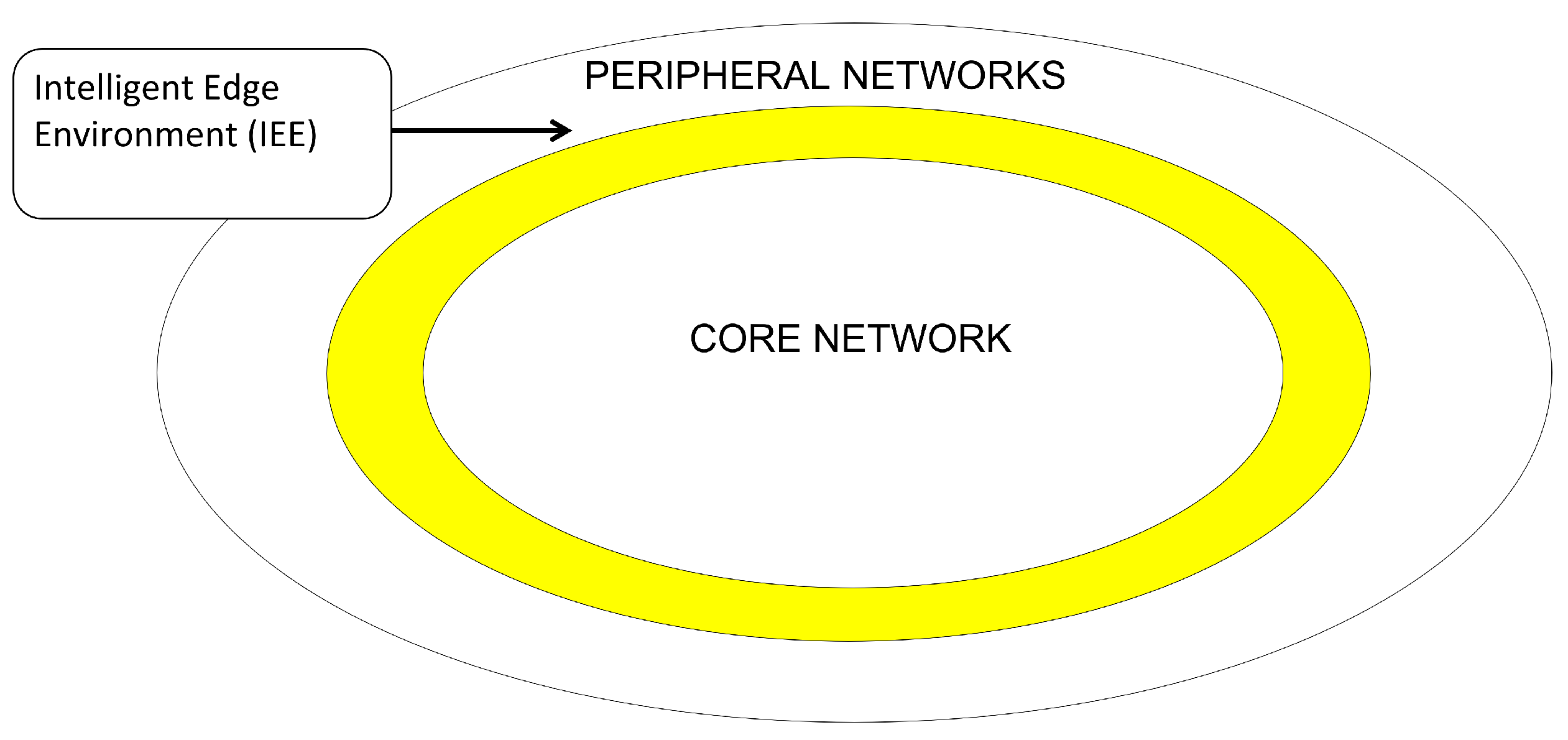
Figure 2.
Intelligent Edge Environment Layers
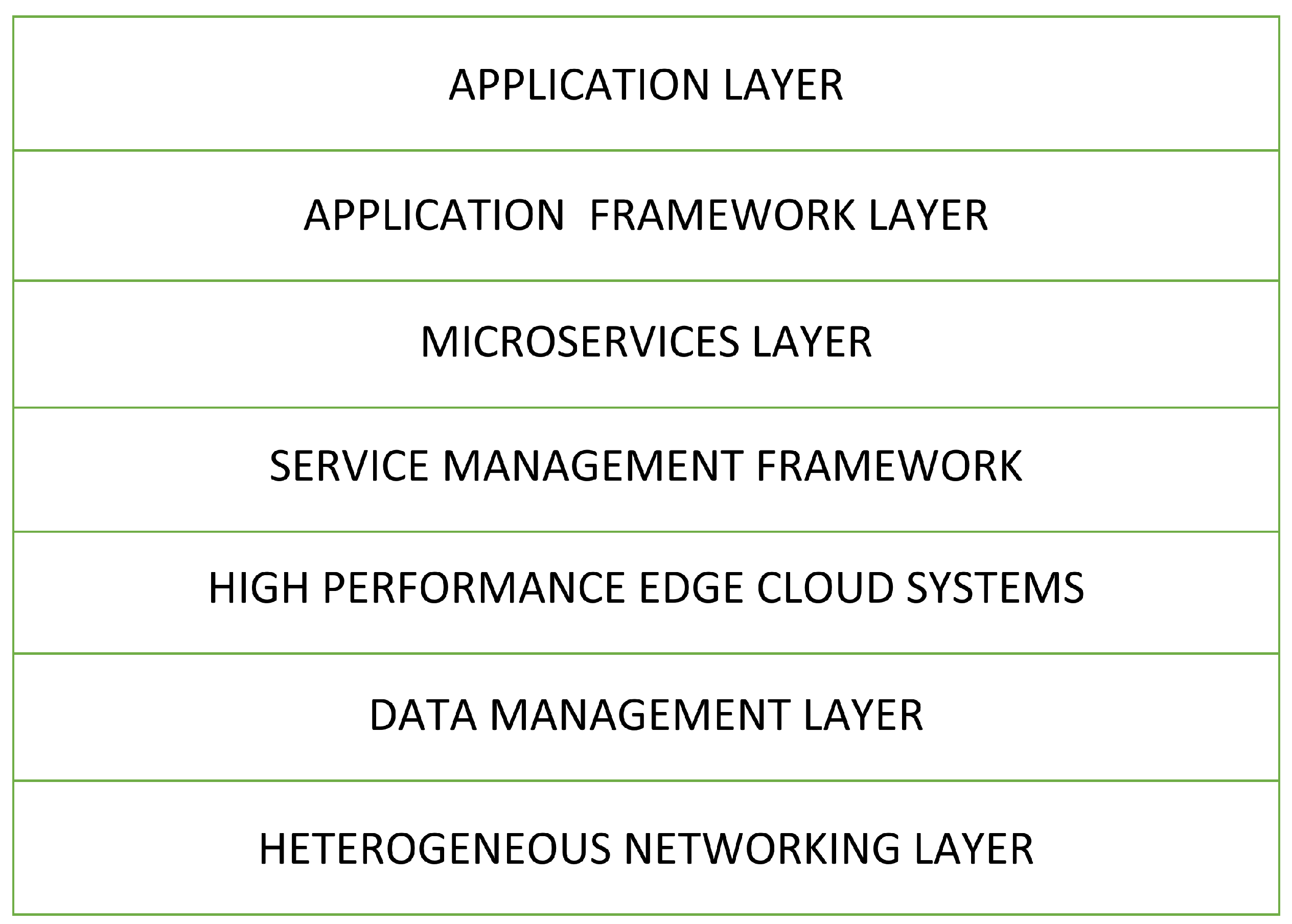
Figure 3.
Simple Resource Allocation Design
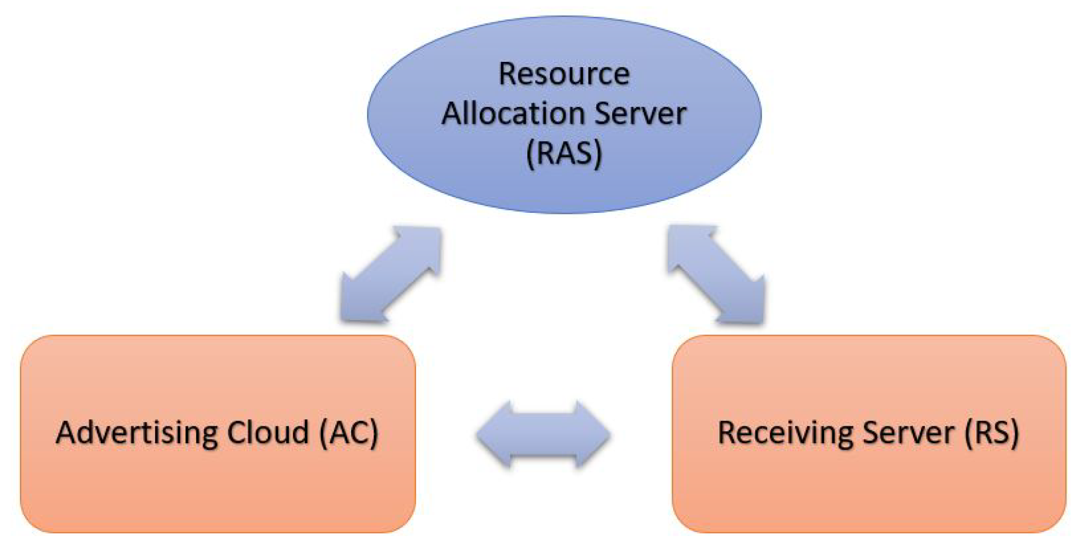
Figure 4.
Migration between SA to CB
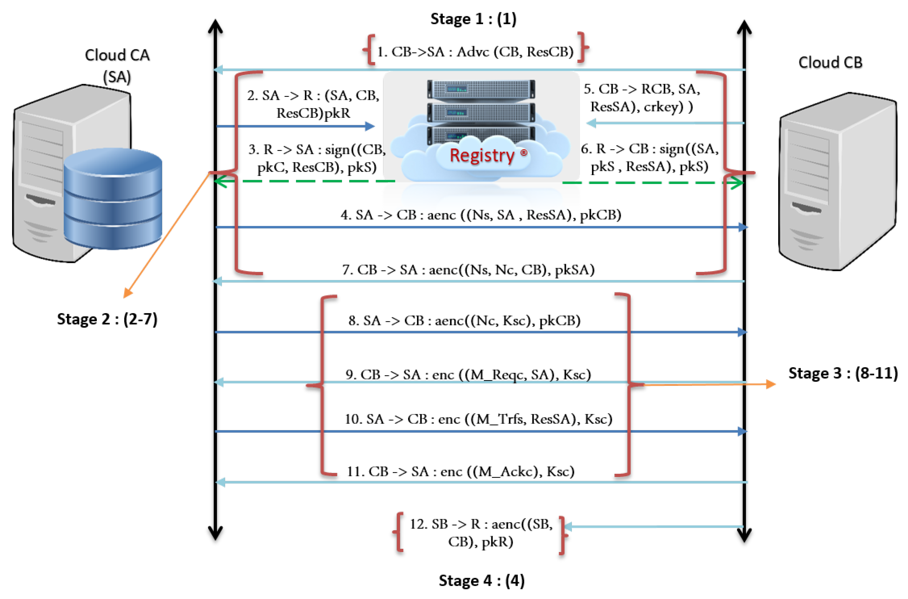
Figure 5.
Capability Structure
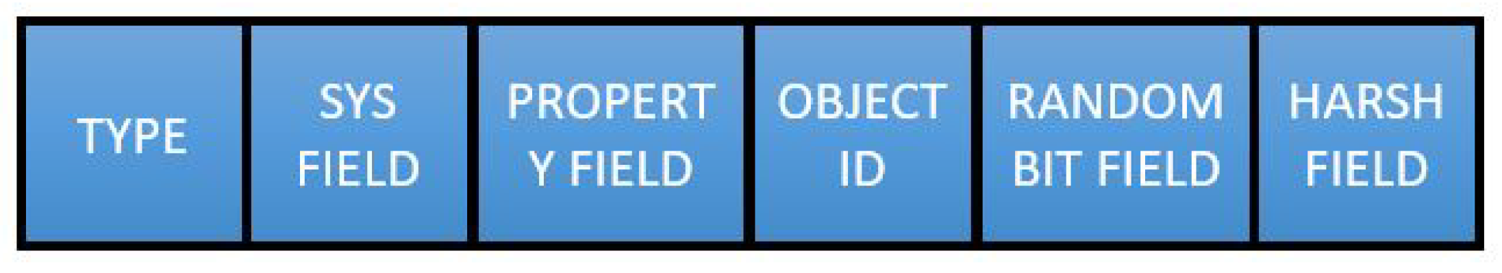
Figure 6.
Capability Structure - SYS FIELD
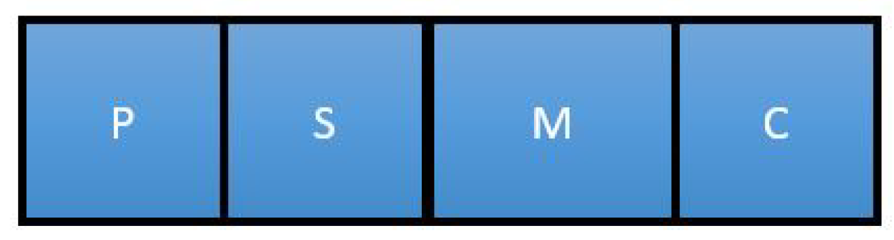
Figure 7.
Effect of Introducing SMF in the client-server environment
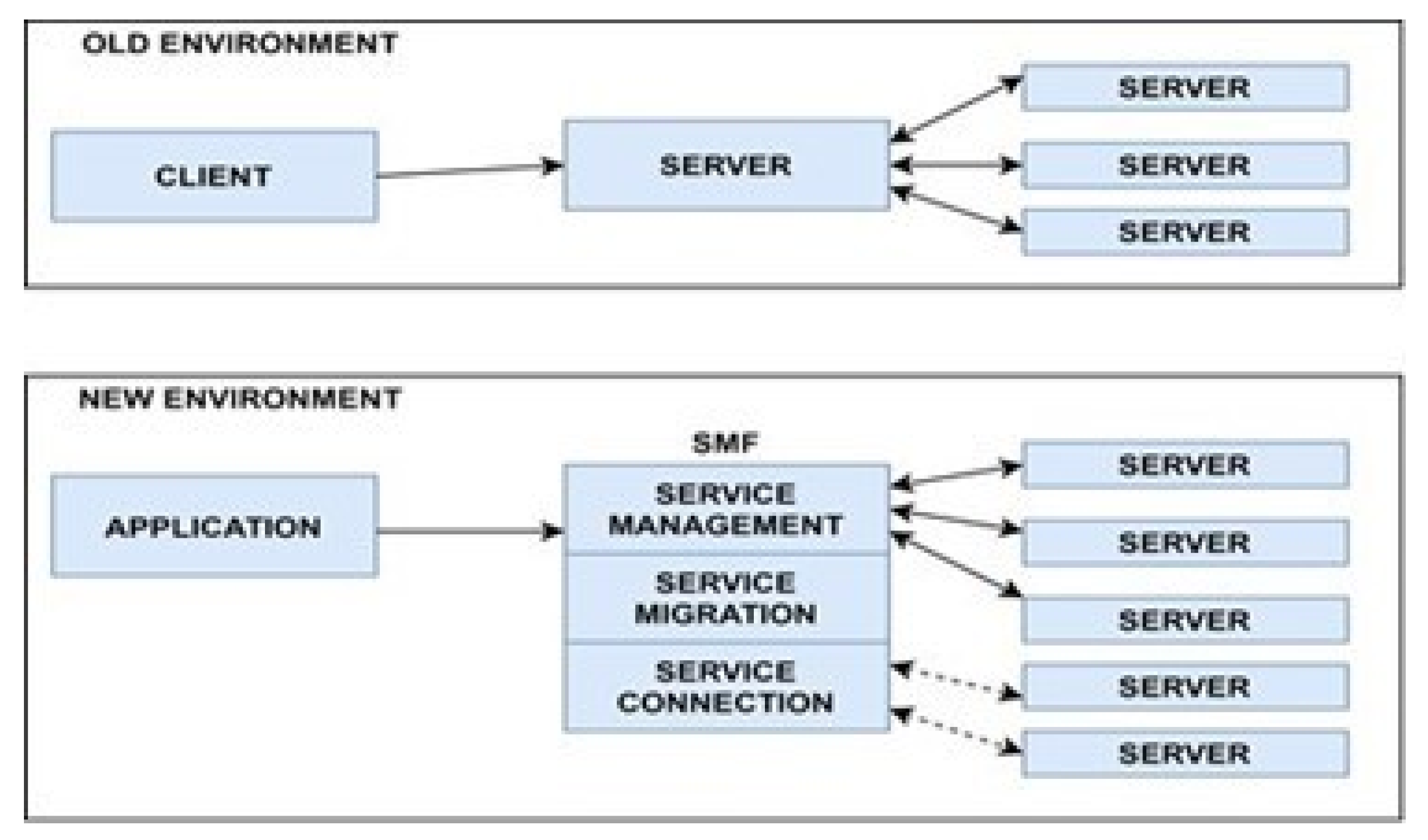
Figure 8.
Service Migration Prototype
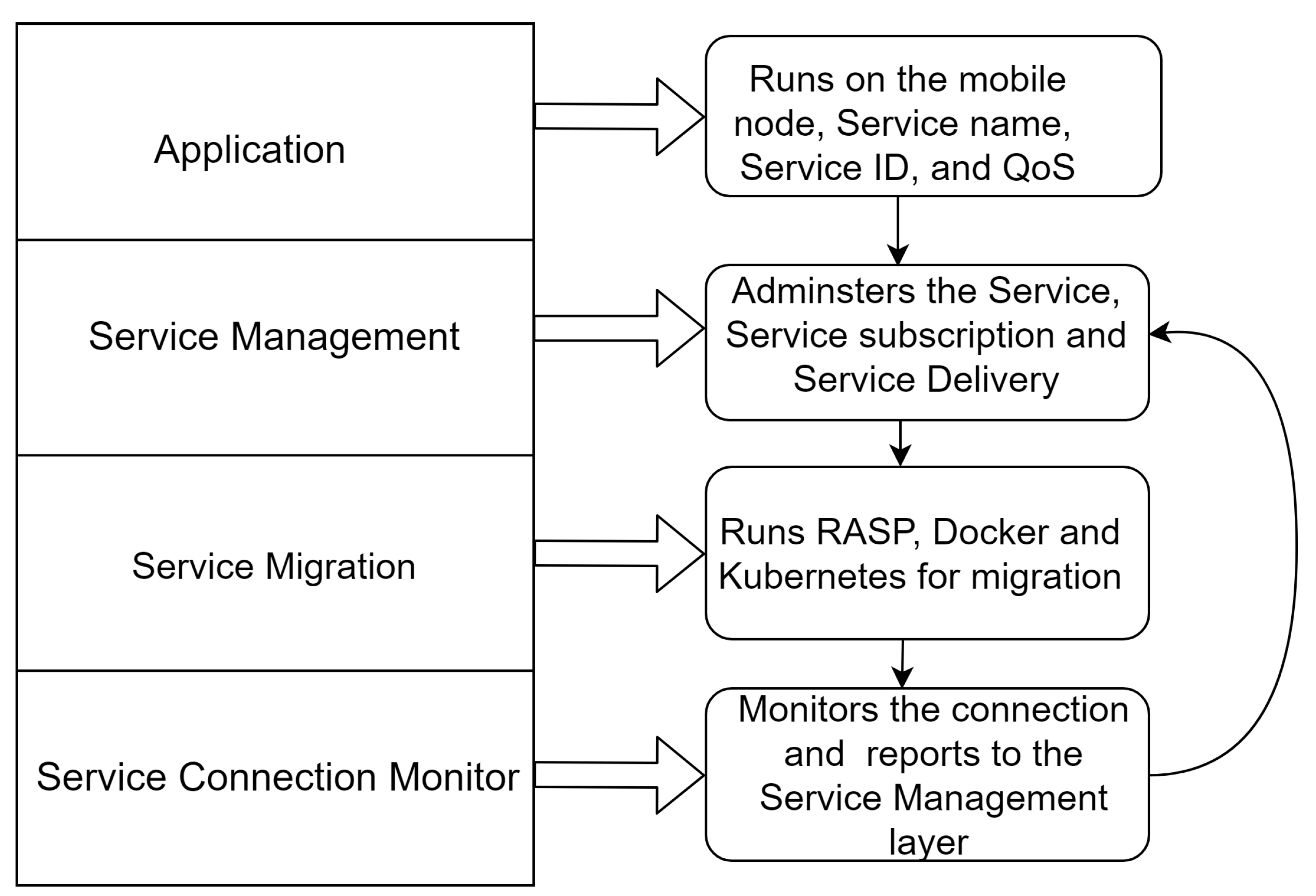
Figure 9.
Secure Service Protocol
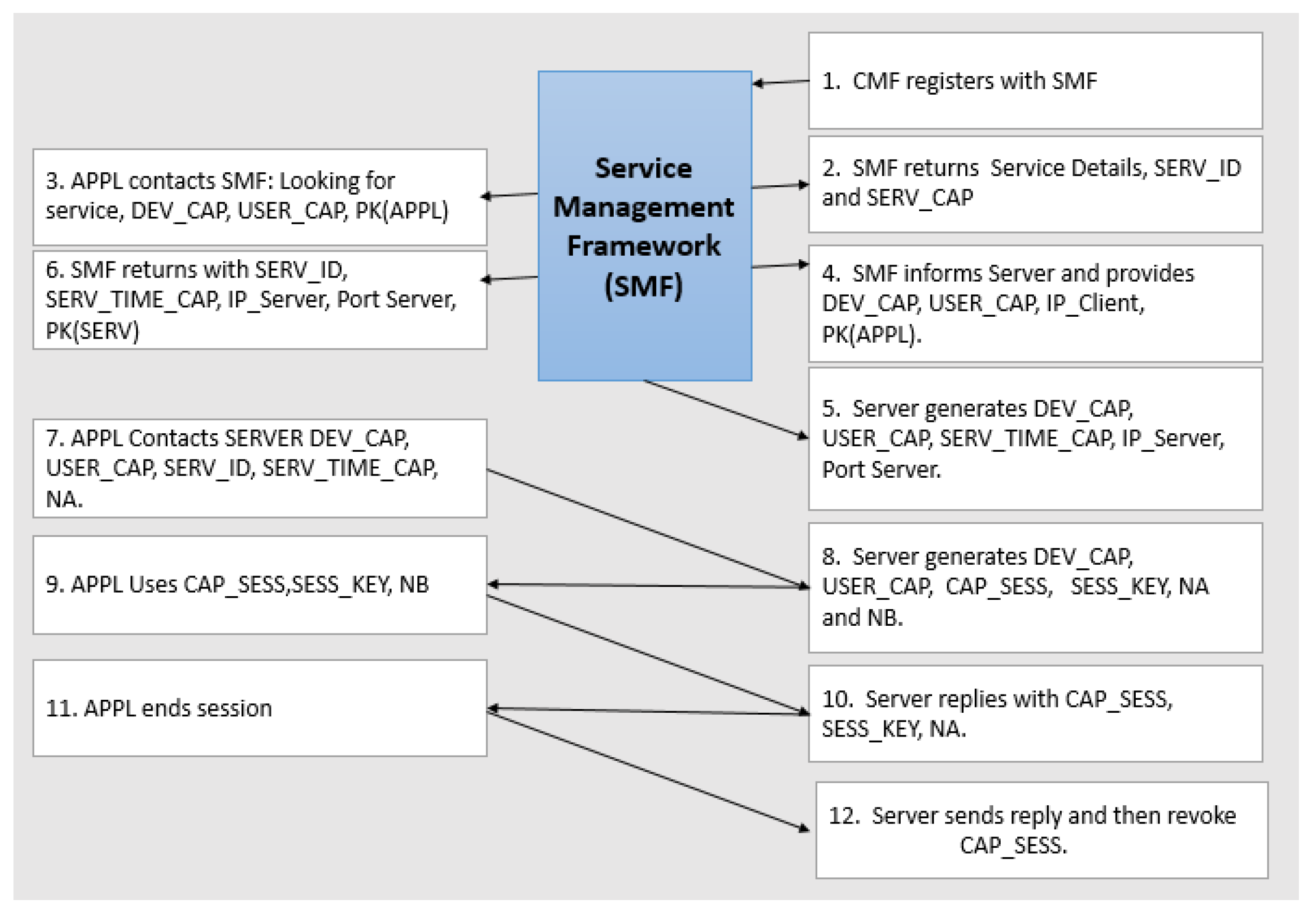
Figure 10.
SSP protocols Results
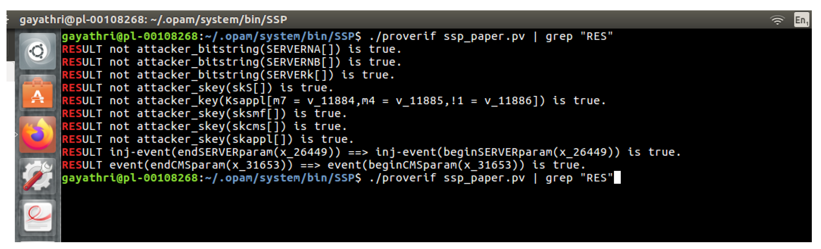
Figure 11.
Basic capability System Library (BCSL)
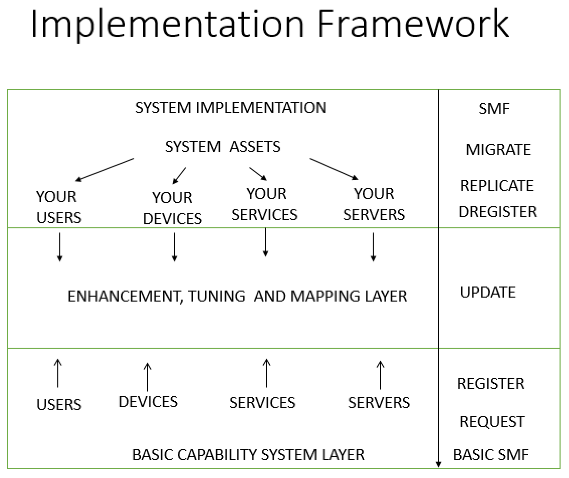
Figure 12.
Fuxfs Multithread
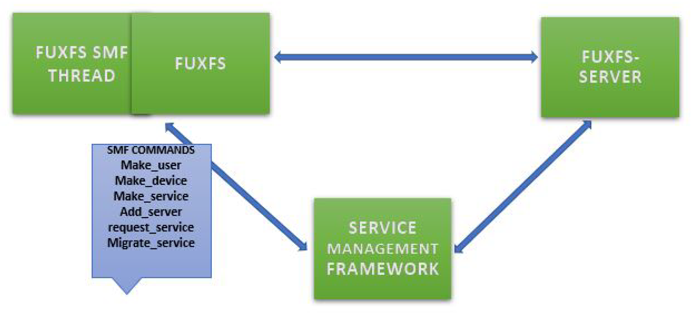
Figure 13.
FUSE Architecture with NMS
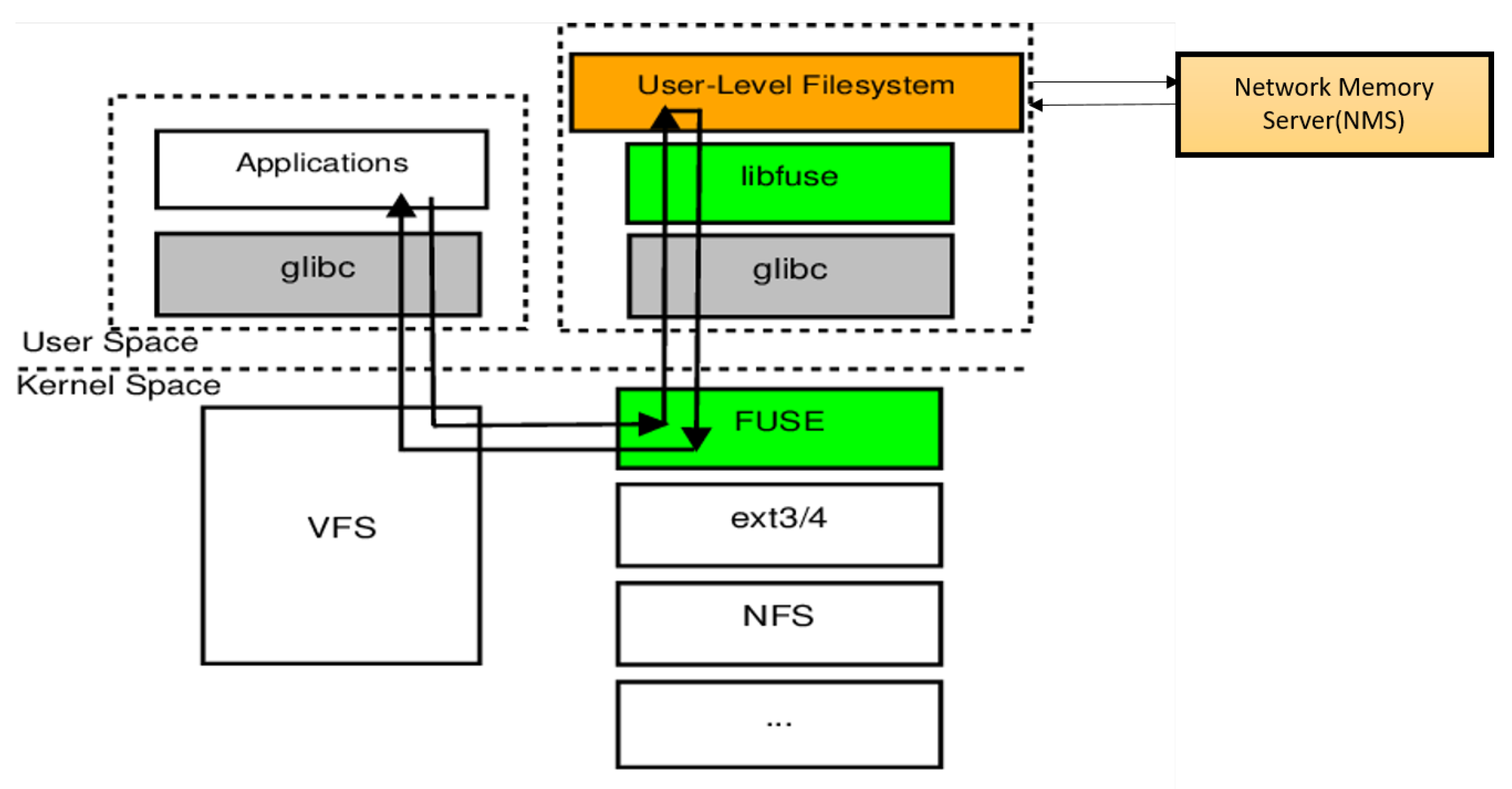
Figure 14.
SMF (top left), FUSE Client (bottom left) and NMS (top right) and Docker Status (bottom right): NMS running at a different location using the SMF
Figure 14.
SMF (top left), FUSE Client (bottom left) and NMS (top right) and Docker Status (bottom right): NMS running at a different location using the SMF
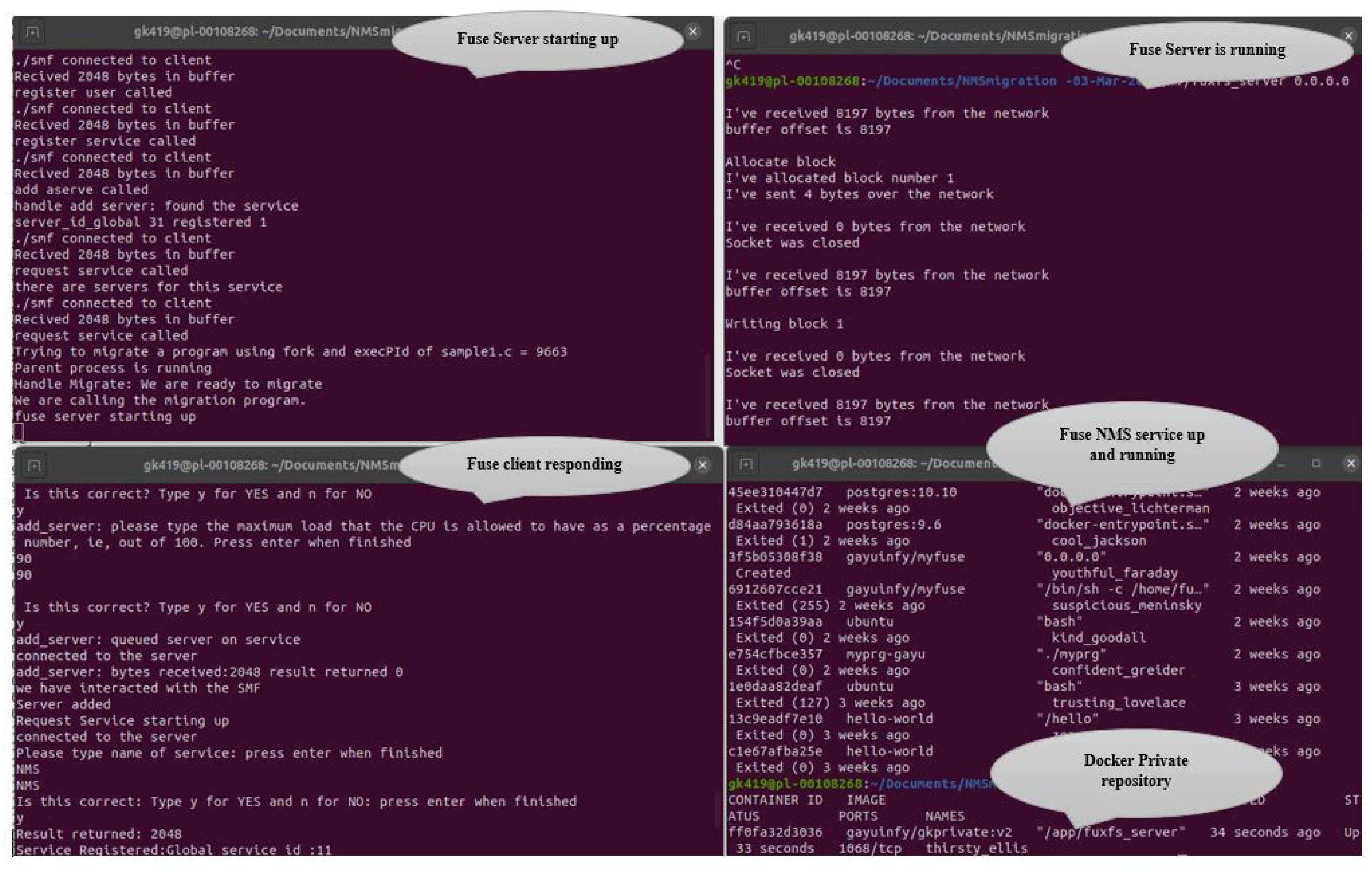
Table 4.
General Notations
| Notations | Explanation |
|---|---|
| CMS | Cloud Management System |
| SMF | Service Management Framework |
| APPL | Applications |
| Chosen Server | The SMF chooses a server of that service |
| PK(SMF)/PK(APPL)/PK(SERV) | Public key of SMF/APPL/Server |
| SK(SMF)/SK(APPL)/SK(SERV)/ | Private key of SMF/APPL/Server |
| SESS KEY | Session key |
| NA and NB | Nonce of NA and NB |
| Register Service | CMS contacts to Register the Service |
| Service Details | Servers, keys and running services. |
| Service Registered | The SMF registers the Service |
| SERV ID | Service ID |
| SERV CAP | Service Capability |
| DEV CAP | The Capability for the Device |
| Request service | Request to an appropriate server |
| USER CAP | User of the Application |
| CAP SESS | User of the Application |
| Service Name | Name of the services |
| Service Version | Service Version |
| IP Client | IP address of Client |
| SERV TIME CAP | proxy capability |
| IP Server | IP address of Server |
| Port Server | TCP Port of Service |
| Usage request | SMF contacts the server |
| Usage request accepted | The Server accepts the request |
| Request service accepted | SMF returns all the details |
| Session Start Request | Time capability sends start request |
| Service request | The application requests service |
| Service request done | The application gets service |
| Request Details | Details of APPL request. |
| Result Details | Details of chose server result. |
| Session End Request | The application terminates the session |
| Session End Req accepted | Server terminates session |
Table 5.
QUERY ATTACKER() Results using ProVerif
| Security Properties | CMF | SMF | ERVER | APPL |
|---|---|---|---|---|
| Private Keys | True | True | True | True |
| Session Key | - | - | True | True |
| Nonces | - | - | True | - |
| Event Begin() | True | - | - | - |
| Event end() | True | - | - | - |
| inj-event begin() | - | - | True | - |
| inj-event-end() | - | - | True | - |
Disclaimer/Publisher’s Note: The statements, opinions and data contained in all publications are solely those of the individual author(s) and contributor(s) and not of MDPI and/or the editor(s). MDPI and/or the editor(s) disclaim responsibility for any injury to people or property resulting from any ideas, methods, instructions or products referred to in the content. |
© 2024 by the authors. Licensee MDPI, Basel, Switzerland. This article is an open access article distributed under the terms and conditions of the Creative Commons Attribution (CC BY) license (http://creativecommons.org/licenses/by/4.0/).
Copyright: This open access article is published under a Creative Commons CC BY 4.0 license, which permit the free download, distribution, and reuse, provided that the author and preprint are cited in any reuse.


