
Submitted:
11 July 2024
Posted:
11 July 2024
You are already at the latest version
Abstract
In this study, unlike conventional methods for producing vanadium (3.5+) electrolyte by VOSO4 and V2O5, a batch-type hydrothermal reactor was used to produce a vanadium (3.5+) electrolyte for vanadium redox flow batteries through a reduction reaction. The starting material, V2O5, was mixed with different concentrations of citric acid (0.8M, 1.2M, 1.6M, 2.0M) as reducing agent and stirred using a hot plate at 90°C for 60 minutes to achieve complete dispersion in the solution. The resulting solution was then subjected to a hydrothermal reduction reaction in a furnace at 150°C for 24 hours to produce vanadium (3.5+). The mixed state of the produced vanadium (3+) and vanadium (4+) was confirmed using UV-vis spectroscopy. Electrochemical properties were investigated through CV analysis, confirming that the optimal concentration was 1.6M. Charge and discharge experiments were conducted to compare the current efficiency, energy efficiency, and voltage efficiency of the electrolyte prepared by the hydrothermal reduction process and the electrolyte prepared by VOSO4. As a result, the electrolyte produced through the hydrothermal reduction process showed improved performance in all efficiencies. The results shows that vanadium (3.5+) electrolyte could be easily produced through a reaction process using citric acid.
Keywords:
Vanadium sulfate (VOSO4)
; Vanadium pentoxide (V2O5)
; Electrolyte
; Citric acid
; Hydrothermal reduction reaction (HRR)
; Vanadium redox flow battery (VRFB)
1. Introduction
With the market acceleration for energy storage devices worldwide, the related market is growing continuously to meet the demand of increasing energy transformation devices. In particular, energy storage devices are one of the most important systems for strengthening the power grid stability as it uses energy mix and distributed power [1,2]. Therefore, energy storage devices are receiving increased attention from researchers as various new renewable power sources enter the grid. Energy storage system can be divided into physical storage and chemical storage. Physical storage methods include flywheels, supercapacitors, and compressed air energy storage systems [3,4,5]. One of the conventional chemical storage methods is redox flow battery (RFB). Different conditions of the energy storage devices for power storage should be reviewed for their stability, long lifespan, and reusability. Among different energy storage devices, RFB is generally used as it is safe, can be reused, and the capacity can be increased easily. Moreover, using RFB the output and capacity can be controlled independently. Unlike conventional secondary batteries, RFB operates on the principle that the active material in the electrolyte is charged and discharged through oxidation and reduction reactions. It is an electrochemical power storage system that stores chemical energy of electrolyte as electrical energy [6]. Research on RFB began in 1974 at NASA in the United States, and active research is being conducted on redox couples, electrochemical mechanisms, etc. The basic structure of RFB is shown in Figure 1 [7].
The structure comprises electrolyte tanks that store active materials with different oxidation state, a pump that circulates the active materials during charging and discharging, an ion exchange membrane that exchanges hydrogen ions, and electrodes that convert chemical energy of the electrolyte into electrical energy. Most of all, an all-vanadium redox flow battery (VRFB) is recognized as one of the most promising candidates for commercialization from the industrial field. With regard to these, numerous researches are focused on the development of compartments in battery which comprised of electrode, membrane and electrolyte. The commercialization of VRFB, however, is still hindered due to the expensive cell components despite of advantages. In particular vanadium electrolyte accounts for a large portion of VRFB costs because of the need for expensive vanadium precursor materials and the high cost of electrolyte production. For instance, for systems of 10 kW/120 kWh, the cost for vanadium and electrolyte production cost account for 40 and 41%, respectively, of the total energy cost [8]. Furthermore, the portion of the electrolyte cost in the total VRFB cost increases with energy capacity of a system [9,10]. Therefore, cost-effective production of VRFB electrolyte must be developed to achieve broader acceptance of VRFB [11,12,13,14]. The active material is an important component that determines the performance of VRFB. The energy density of a cell depends on the solubility of the active material, and the voltage of the cell is determined by the equilibrium potential of the active material that make up the electrolyte of both cells [15,16,17]. Several studies have been conducted on different organic and inorganic active materials. Many researchers have made efforts to examine and characterize the representative active materials, such as iron/chromium, vanadium/bromine, zinc/bromine, and vanadium [18,19,20]. Among them, the most common active material is vanadium. Because it is composed of four different oxidation states in two electrolyte solutions, contamination of both electrolytes due to the crossover inside the cell does not occur [21,22]. Therefore, it has the advantage of being reusable. However, there are disadvantages as well such as a large amount of vanadium precursor is not completely soluble in aqueous solution and vanadium (5+) is precipitated when the battery is operated at a high temperature [23,24]. In addition, in the case of the pure vanadium (4+) precursor, the high manufacturing cost makes it difficult to mass-produce the electrolyte, which is an obstacle to commercialization. Recently, manufacturing of vanadium (3.5+), which is a mixture of vanadium (3+) and vanadium (4+), has attracted considerable attention. The electrochemical method used for production by Oxchem, which has already been commercialized, is the most commonly used method. It is currently manufactured by mixing vanadium (3+) and vanadium (4+) produced from a vanadium (5+) solution obtained through electrochemical cell method. In addition, Heo et al. reported successful production of vanadium (3.5+) from vanadium (4+) using a Pt/Ru catalyst layer and formic acid [18]. However, such a process may require sophisticated process control and incur an extremely high initial cost for mass production. The vanadium (3.5+) electrolyte, which is an equimolar mixture of vanadium (4+) and vanadium (3+) electrolyte, is especially preferred in industry as both positive and negative electrolytes because VRFB can be operated without initial re-balancing of its positive and negative capacity. A full charging of VRFB with the use of the same vanadium (3.5+) electrolyte for positive and negative electrodes results in vanadium (5+) and vanadium (2+) electrolyte at the positive and negative electrodes, respectively. In most cases, V2O5 is commonly used as a vanadium source for preparing vanadium (3.5+) electrolyte because of its low cost, compared with other vanadium precursors. The conventional route for preparing V3.5+ electrolyte from V2O5 includes the chemical reduction of vanadium (5+) to vanadium (4+) with a reducing agent and the electrolysis of vanadium (4+) electrolyte to produce vanadium (3+) electrolyte. The reduction of vanadium (5+) to vanadium (4+) can easily be achieved with a residue-free organic reducing agent such as oxalic acid [16,17,18]. However, the reduction of vanadium (4+) to vanadium (3+) with organic reducing agent is quite sluggish, which presents a significant difficulty in practical chemical production of vanadium (3.5+) electrolyte.
To the best Knowledge, no one reported production method via hydrothermal reduction process utilizing weak acid. Therefore, this study confirmed the possibility of mass production of vanadium (3.5+) electrolyte using a simple batch type process in a hydrothermal reactor. Also, we will try to seek organic reducing agent to produce accurate vanadium (3.5+) and apply it to our experiments.
2. Experimental
2.1. Chemicals
Vanadium sulfate (VOSO4 XH2O, 97%, Japan), Vanadium Pentoxide V2O5(99.5%, Sigma-Aldrich, USA) were purchased to manufacture the vanadium electrolyte. Also, sulfuric acid (H2SO4, 98%, Daejung, Republic Korea) was purchased. Ultra-pure water was used to prepare a sulfuric acid solution. Additionally, Citric acid anhydrous and Oxalic acid dehydrate used as a reducing agent were purchased from Alfa Aesar (United Kingdom) and Duksan reagents (98%, Republic Korea). All chemicals were used as-received without any further purification. VOSO4 and V2O5 precursors were stored separately in a storage container to avoid contact with moisture, and the temperature was maintained at 20 °C.
2.2. Preparation of Vavadium(3.5+)Electrolyte from Vanadium(4+)
The manufacturing method for 1 liter of 1.6M vanadium (4+) solution is as follows: mixing 268.86g of VOSO4· XH2O powder in 163.2ml of sulfuric acid, then add water until the total volume reaches 1 liter. The solutions were stirred for 24h to prepare homogeneous electrolyte which is 1.6M VOSO4 + 3M H2SO4. The prepared vanadium (4+) electrolyte solution is charged to produce vanadium (3+) in the negative solution and vanadium (5+) in the positive solution. Then, 201.71g(1.6M) of reducing agent, oxalic acid is added to vanadium (5+) solution to produce vanadium (4+) and stirred at 70°C for 24 hours. Finally, The Equal amounts of the both vanadium (3+) and vanadium (4+) were mixed to prepare vanadium (3.5+) electrolyte. The mechanism of vanadium (3.5+) electrolyte is shown in Figure 2.
2.3. Preparation of Vanadium (3.5+) from Vanadium (5+)
The detailed process for preparation from V2O5 is shown in Figure 3. To prepare 1 liter of 0.8M vanadium (5+) solution, mix 146.24g of V2O5 powder in 163.2ml of sulfuric acid, and then add 100.86g (0.8M) of oxalic acid as a reducing agent was added to produce the vanadium (4+) electrolyte solution. At this time, the amount of oxalic acid was equal to V2O5 and reacted to obtain vanadium (4+). Through charging vanadium (4+) solution, vanadium (3+) electrolyte in the negative solution and vanadium (5+) electrolyte in the positive solution were produced. The vanadium (5+) electrolyte in the positive solution was reduced using a reducing agent again to produce vanadium (4+) electrolyte, which is mixed with the vanadium (3+) from the cathode to produce the vanadium (3.5+) electrolyte solution.
2.4. Hydrothermal Reduction (HRR) of Vanadium(4+) and Vanadium (5+) Solution
Figure 4 shows that the preparation process of vanadium (3.5+) electrolyte from VOSO4 and V2O5 by hydrothermal reductio reaction. A 20-liter hydrothermal reactor was manufactured by us and used in the HRR process for the production of vanadium (3.5+) electrolytes. First, when VOSO4 was used as the precursor, the different concentrations 1.6M, 3.2M and 6.4M of oxalic acid were added to the vanadium (4+) electrolyte solutions. Secondly, when V2O5 was used as the precursor, the different concentrations 0.8M, 1.2M, 1.6M and 2.0M of citric acid were added to the vanadium (5+) electrolyte solutions, followed by stirring at 90° C for 60 min on a hot plate to completely disperse weak acid in the solutions. The prepared solutions were then transferred to the hydrothermal reactor. After filling only 60% of the reactor, it was placed in a box furnace and the reaction allowed to proceed. Only 60% of the reactor was filled to prevent any overflow of the solution on opening the reactor after completing the reaction because weak acid is decomposed to release CO2, which increases the pressure inside the reactor. The reaction temperature was increased at a rate of 5 ℃ per minute to 150 ℃ in a furnace, at which it was maintained for 12hr.
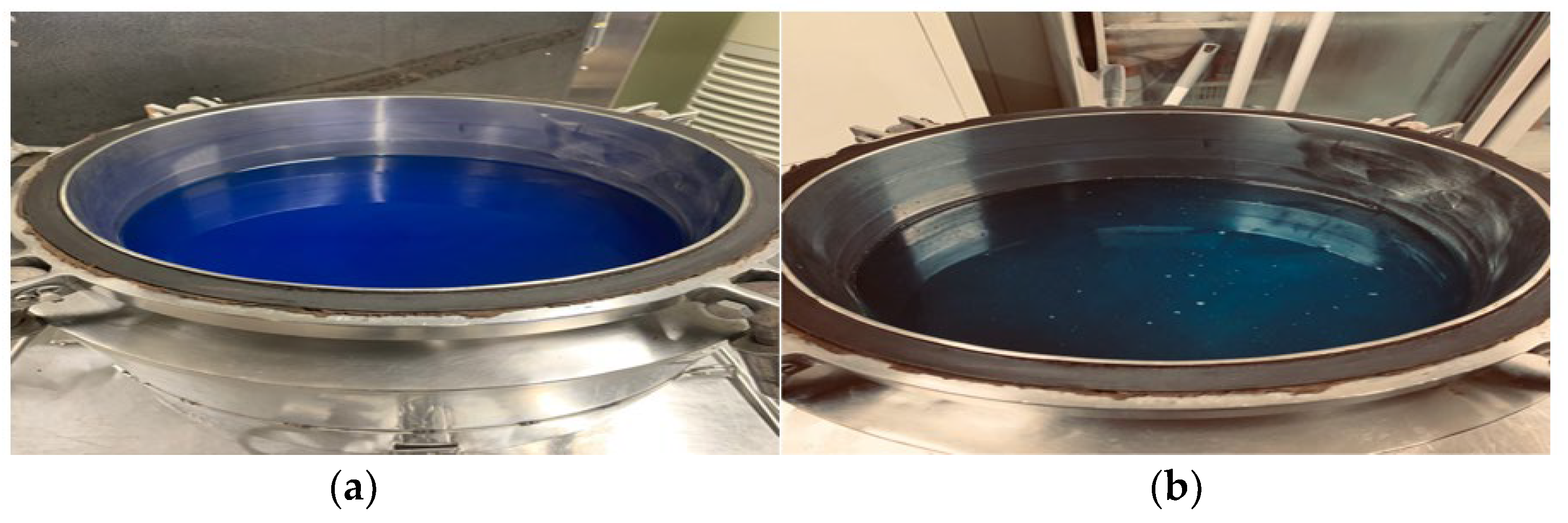
Temperature and reaction time were determined based on the presence or absence of residual weak acid after reaction. After completing the reaction, the temperature of the reactor was slowly lowered. Once the temperature was completely lowered, the status of the sample was checked after opening the reactor. The mixed state (vanadium (3+) and vanadium (4+)) of the prepared sample was confirmed by UV-vis spectroscopy (Shimazu, Japan). The vanadium (3.5+) electrolyte produced in the 20-liter reactor is shown in Figure5. By visually inspecting the color of the electrolyte in the reactor, it was confirm to have a vanadium (3.5+)
Figure 5.
The Production of vanadium electrolyte (3.5+) using a 20-liter hydrothermal reactor: (a): vanadium (4+) in 20L hydrothermal reactor, (b): vanadium (3.5+) appearance.
Figure 5.
The Production of vanadium electrolyte (3.5+) using a 20-liter hydrothermal reactor: (a): vanadium (4+) in 20L hydrothermal reactor, (b): vanadium (3.5+) appearance.
2.4. Electrochemical Analysis
Cyclic voltammetry (CV) was used to analyze the electrochemical properties of the samples prepared with different citric acid concentrations. The potentiostat/galvanostat(PGSTAT 302) was used for CV measurement. A three-electrode system was used: a carbon rod was used as a working electrode, Ag/AgCl (3M KCl) was used as a reference electrode, and a Pt wire was used as a counter electrode. The scan was carried out at room temperature at a scan rate of 20mV/s.
2.5. VRFB Cell Test
The vanadium RFB single cell was assembled by sandwiching a Nafion 212 membrane (5 cm 5 cm, Dupont) between two pieces of carbon felts (5cm 5cm, 5mm, Daedong carbon, Korea), used as current collectors, fixed by two conductive plastic plates. The corresponding charge and discharge tests were conducted using the battery test system (5V/6A, FamTech, Korea) at the current density to 80 mA cm-2. The upper and lower limits of the charge and discharge voltage were controlled to be 1.7 V and 0.8V respectively, in order to avoid the corrosion of carbon felts and the electrode side reaction. Charging and discharging were conducted for 50 cycles, and the current efficiency, voltage efficiency and energy efficiency of the battery were calculated the following equation:
3. Result and Discussion
3.1. UV Characteristics and Concentration Analysis of Vanadium Electrolyte
Figure 5 (a) depits the UV spectra characteristics of vanadium electrolytes for vanadium (3+), Fig(b) and (d) show a linearized graph of vanadium(3+,4+) concentration against absorbance values. In the vanadium (3+) electrolyte solution, peaks are observed at 400nm and 620nm. (c) shows vanadium(4+)electrolyte reducing from vanadium(5+) peaks is observed at 770nm.
Figure 6.
UV spectrum charteristic and correlation corresponding to the concentration of vanadium electrolyte soiution.
Figure 6.
UV spectrum charteristic and correlation corresponding to the concentration of vanadium electrolyte soiution.
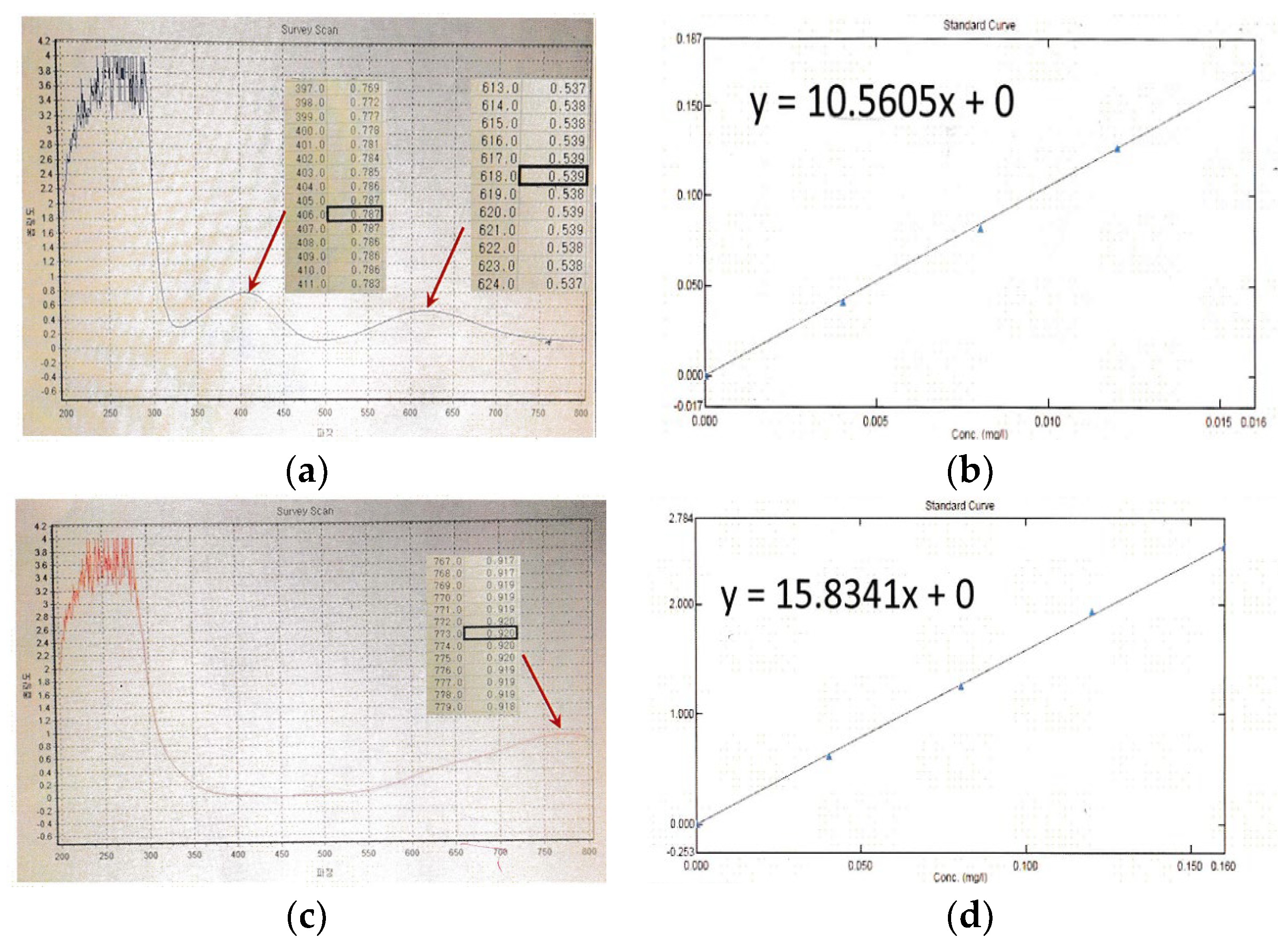
Typically, vanadium (3+) electrolyte is produced by reduction from vanadium(4+) electrolyte during charging processes, therefore vanadium(3+) electrolyte contains vanadium(4+) electrolyte. This means that when analyzing vanadium(3+)electrolyte, the characteristics of the UV spectrum of the vanadium(4+) must be considered. Since the two components are mixed, it is very reasonable to analyze vanadium(3+) at 400nm, where the peak spectrum of vanadium(4+) electrolyte does not appear. Also, Figure 7 appears that the UV spectra characteristics of vanadium (3.5+) electrolyte from VOSO4 and V2O5 by hydrothermal reductio reaction. Figure 7(a) shows that varying the concentration of oxalic acid is added to VOSO4. solution. Figure 7(b) shows that varying the concentration of citric acid is added to V2O5 solution.
In this part, the possibility of vanadium (3.5+) production via hydrothermal reduction of vanadium (5+) by different concentrations of oxalic acid and citric acid was confirmed. The different ratios of oxalic acid concentration to VOSO4 concentration were 0.5(0.8M), 1.0(1.6M), 1.5(2.4M), 2.0(3.2M) and 4.0(6.4M) (Fig6(a)). The different ratios of citric acid concentration to V2O5 concentration were 1.0(0.8M), 1.25(1M), 2.0(1.6M), 2.5(2M), 4.0(3.2M) and 6.0(4.8M) (Fig6(b)). The different ratios of vanadium (3+) to vanadium (4+) at different oxalic acid and citric acid concentrations were measured by UV-vis spectroscopy. When examining absorbance according to the concentration of oxalic acid, a curve was found where the absorbance of vanadium (IV) decreases at 750nm and the absorbance of vanadium (III) increases. This curve was observed at a concentration of 6.4M. Therefore, this concentration was determined to be optimal. The reason for adding a high concentration of oxalic acid is because oxalic acid has a high activation energy required for oxidation, resulting in a slowing down of the reduction reaction rate of vanadium (4+). For this reason, citric acid was used reducing agent. When examining citric acid, the peak at 750 nm, corresponding to vanadium (4+), decreased in intensity, and the peak at 400 nm, corresponding to vanadium (3+), increased in intensity. This confirms that V2O5 is reduced to vanadium (4+) and vanadium (3+) by citric acid via hydrothermal reaction. Figure 6(c) illustrates the oxidation among the four selected concentrations of citric acid. This shows that the change in the ratio of vanadium (3+) and vanadium (4+) according to citric acid concentration. This suggests that vanadium (3.5+) can be produced in a certain HRR process by controlling citric acid concentration. When the reaction was conducted at a citric acid to V2O5 ratio of 2.0(1.6M), an electrolyte with the same vanadium (3+)-to-vanadium (4+) ratio was prepared. In addition, it was confirmed that citric acid was decomposed to CO2 by analyzing the bubbles that came out when the reactor was opened after process completion. The ratio of citric acid to V2O5 was 2.5(2M), complete conversion to the vanadium (3+) was achieved, which can be determined by the almost complete disappearance of the peak at 750 nm. Therefore, the vanadium (5+) precursor can be completely converted to vanadium (3+) at a citric acid to vanadium (5+) precursor ratio of 2.5(2M).
3.2. Electrochemical Properties of the Vanadium (3.5+) Electrolytes by HRR
Figure 8 shows cyclic voltammetry of prepared electrolytes with different concentration of reducing agents. The electrochemical properties of each electrolyte were determined by cyclic voltammetry under a few assumptions. The first assumption was that two oxidation peaks appeared when the ratios of citric acid to precursor were 1.0(0.8M) and 1.5(1.2M), which was probably due to the difference in the ratio of vanadium (3+) to vanadium (4+) in the electrolyte. As confirmed by UV-vis spectroscopy (section 3.1), vanadium (4+) was predominant in the electrolyte when the ratio of citric acid to precursor was less than 2.0, which may appear as an incomplete reversible reaction in the CV phase. The other assumption is that vanadium (5+) cannot be completely reduced to the vanadium (4+), which may appear as two oxidation peaks on the voltammogram. For vanadium (4+), an oxidation peak is usually found at 1.0 V (vs. Ag/AgCl). Therefore, it was hypothesized that the peak at 1.2 V was due to the formation of poly-vanadium. To analyze this point, Oxalic acid is a reducing agent commonly used to reduce V2O5 to VOSO4, and is considered the most suitable material to confirm the two above-mentioned assumptions because it is completely decomposed to CO2 after the reaction. The electrochemical properties can obtain when a small amount of oxalic acid was mixed with citric acid can be seen as a reversal to V2O5 or poly-vanadium at the oxidation voltage because unreduced V2O5 was retained when ratios of citric acid to precursor were 1.0(0.8M) and 1.5(1.2M). Therefore, in this result, the optimal ratio of citric acid to vanadium (5+) precursor was 2.0(1.6M) for the hydrothermal reduction to vanadium (3.5+). Also, the optimal ratio of oxalic acid to vanadium (4+) precursor was 4.0(6.4M) for the hydrothermal reduction to vanadium (3.5+). Because the detection was due to vanadium (4+) and vanadium (3+) being present in a 1:1 ratio. When oxalic acid was added in excess of twice the amount of VOSO4, vanadium (3+) began to be detected due to reduction reaction.
3.3. Performance of VRFB Using Vanadium (3.5+) Electrolytes by Electricity Reduction and HRR
The performance of the VRFB was compared with vanadium (3.5+) obtained using the electricity reduction VOSO4 and that prepared by the HRR process. Electrochemical properties in the V (2+)/V (3+) and V (4+)/V (5+) regions were analyzed by CV. Figure 9 shows the CV curves of vanadium (3.5+) electrolyte solution. It was observed that the electrical characteristics of the vanadium (3.5+) electrolyte prepared from precusor VOSO4 and V2O5 were almost similar. The vanadium (3.5+) electrolyte prepared herein showed higher current density than the conventional VOSO4 electrolyte, and the oxidation/reduction voltage was relatively similar for the two electrolytes. This result demonstrates that vanadium (3.5+) electrolyte solutions can be produced from the low-cost V2O5. Table 1 was presented the change for current and potential corresponding to the oxidation peak and reduction peak of the vanadium (3.5+) electrolyte. In this context, when the oxidation current/reduction current ratio is close to 1 during the oxidation from vanadium (4+) to vanadium (5+), it is considered to indicate good reversibility. Figure 10 showed the current efficiency, voltage efficiency, and energy efficiency. The performance of VRFB cells show in Table 2. For the prepared vanadium (3.5+) electrolyte from 1.6M VOSO4 + 3M H2SO4 electrolyte, the current, voltage, and energy efficiency values were 94.82%, 81.69% and 77.48% respectively. Also, for the prepared vanadium (3.5+) electrolyte from 0.8M V2O5 +3M H2SO4, the current, voltage, and energy efficiency values were 95.38%, 84.03% and 84.96%, which shows improved performance compared to the commercialized electrolyte. It can be assumed that the protons in the citric acid in 0.8M V2O5 +3M H2SO4 were retained in the electrolyte, which not only facilitated charging and discharging, but also prevented deterioration of electrolyte performance. After conducting a battery performance evaluation, it was observed that there was not a significant increase in current efficiency, the overall performance of the battery improved due to enhanced voltage efficiency.
4. Conclusion
In this study, Using the cost-effective V2O5 precursor, the one-pot hydrothermal reduction process simplified the production of vanadium (3.5+) electrolyte in large quantities, thereby saving time and reducing costs. A vanadium (3.5+) electrolyte was easily prepared by an HRR process using citric acid and it was comparable in performance to the commercialized vanadium (3.5+) manufacturing from VOSO4 precursor, it shows superior battery efficiency compared to existing electrolytes, making it suitable for industrial use, and the process is expected to enable easy mass production. A vanadium (3.5+) electrolyte could be produced when performing the HRR process at a citric acid to V2O5 ratio of 2.0(1.6M). In addition, it was determined that no residual citric acid was left in the electrolyte. The commonly used reducing agent, oxalic acid can reduce vanadium (5+) to vanadium (4+). But to convert vanadium (4+) to vanadium (3+), it must overcome a high chemical potential barrier. For this reason, we used citric acid with high reducing power to overcome the activation energy in hydrothermal synthesis process that supplies external energy.
In the future, we will carefully review the conditions of the HRR process and optimize the mixing ratio of citric acid and oxalic acid to manufacture accurate vanadium (3.5+) for mass production.
References
- Frost & Sullivan. Emerging Technologies in the Energy Storage Market. www. Frost.com: 01/05/2016.
- IEA (International Energy Agency). Energy Storage Technology Roadmap. www.iea.org: 12/06/2024.
- Chen R.; Kim S.; Chang Z. Redox flow batteries: Fundamentals and applications. 2017; pp. 103-118. [CrossRef]
- Ye, R.; Henkensmeier, D.; Yoon, SJ.; Huang, Z. ; D K, Kim.; Chang Z. Redox flow batteries for energy storage: A technology review. JEE Conversion and Storage. 2018; 15:010801. [CrossRef]
- Cui, K.; Xu, L.; Tao, T.; Huang, L.; Li, J.; Hong, J.; Li, H.; Chi, Y. Mechanical behavior of multiscale hybrid fiber reinforced recycled aggregate concrete subject to uniaxial compression. Journal of Building Engineering 2023, 71, 106504. [Google Scholar] [CrossRef]
- Choi, C.; Kim, S.; Kim, R.; Choi, Y.; Kim, S.; Jung, H.-Y.; Yang, J.H.; Kim, H.-T. A review of vanadium electrolytes for vanadium redox flow batteries. Renew. Sustain. Energy Rev. 2017, 69, 263–274. [Google Scholar] [CrossRef]
- Parasuraman, A.; Lim, T.M.; Menictas, C.; Skyllas-Kazacos, M. Review of material research and development for vanadium redox flow battery applications. Electrochimica Acta 2013, 101, 27–40. [Google Scholar] [CrossRef]
- Skyllas-Kazacos, M.; Kazacos, G.; Poon, G.; Verseema, H. Recent advances with UNSW vanadium-based redox flow batteries. Int. J. Energy Res. 2009, 34, 182–189. [Google Scholar] [CrossRef]
- Minke, C.; Kunz, U.; Turek, T. Techno-economic assessment of novel vanadium redox flow batteries with large-area cells. J. Power Sources 2017, 361, 105–114. [Google Scholar] [CrossRef]
- Cao, L.; Skyllas-Kazacos, M.; Menictas, C.; Noack, J. A review of electrolyte additives and impurities in vanadium redox flow batteries. J. Energy Chem. 2018, 27, 1269–1291. [Google Scholar] [CrossRef]
- Minke, C.; Kunz, U.; Turek, T. Techno-economic assessment of novel vanadium redox flow batteries with large-area cells. J. Power Sources 2017, 361, 105–114. [Google Scholar] [CrossRef]
- Kear, G.; Shah, A.A.; Walsh, F.C. Development of the all-vanadium redox flow battery for energy storage: a review of technological, financial and policy aspects. Int. J. Energy Res. 2011, 36, 1105–1120. [Google Scholar] [CrossRef]
- Skyllaskazacos, M.; Chakrabarti, M.H.; Hajimolana, S.A.; Mjalli, F.S.; Saleem, M. Progress in Flow Battery Research and Development. J. Electrochem. Soc. 2011, 158, R55–R79. [Google Scholar] [CrossRef]
- Xi, J.; Wu, Z.; Teng, X.; Zhao, Y.; Chen, L.; Qiu, X. Self-assembled polyelectrolyte multilayer modified Nafion membrane with suppressed vanadium ion crossover for vanadium redox flow batteries. J. Mater. Chem. 2008, 18, 1232–1238. [Google Scholar] [CrossRef]
- Leung, P.; Li, X.; de León, C.P.; Berlouis, L.; Low, C.T.J.; Walsh, F.C. Progress in redox flow batteries, remaining challenges and their applications in energy storage. RSC Adv. 2012, 2, 10125–10156. [Google Scholar] [CrossRef]
- Li, L.; Kim, S.; Wang, W.; Vijayakumar, M.; Nie, Z.; Chen, B.; Zhang, J.; Xia, G.; Hu, J.; Graff, G.; et al. A Stable Vanadium Redox-Flow Battery with High Energy Density for Large-Scale Energy Storage. Adv. Energy Mater. 2011, 1, 394–400. [Google Scholar] [CrossRef]
- Ling, C.; Cao, H.; Chng, M.; Han, M.; Birgersson, E. Pulsating electrolyte flow in a full vanadium redox battery. J. Power Sources 2015, 294, 305–311. [Google Scholar] [CrossRef]
- Ling, C.; Cao, H.; Chng, M.; Han, M.; Birgersson, E. Pulsating electrolyte flow in a full vanadium redox battery. J. Power Sources 2015, 294, 305–311. [Google Scholar] [CrossRef]
- Sum, E.; Rychcik, M.; Skyllas-Kazacos, M. Investigation of the V(V)/V(IV) system for use in the positive half-cell of a redox battery. J. Power Sources 1985, 16, 85–95. [Google Scholar] [CrossRef]
- Singh, P.; Jonshagen, B. Zincbromine battery for energy storage. J. Power Sources 1991, 35, 405–410. [Google Scholar] [CrossRef]
- Vijayakumar, M.; Li, L.; Graff, G.; Liu, J.; Zhang, H.; Yang, Z.; Hu, J.Z. Towards understanding the poor thermal stability of V5+ electrolyte solution in Vanadium Redox Flow Batteries. J. Power Sources 2011, 196, 3669–3672. [Google Scholar] [CrossRef]
- Rahman, F.; Skyllas-Kazacos, M. Solubility of vanadyl sulfate in concentrated sulfuric acid solutions. J. Power Sources 1998, 72, 105–110. [Google Scholar] [CrossRef]
- Heo, J.; Han, J.-Y.; Kim, S.; Yuk, S.; Choi, C.; Kim, R.; Lee, J.-H.; Klassen, A.; Ryi, S.-K.; Kim, H.-T. Catalytic production of impurity-free V3.5+ electrolyte for vanadium redox flow batteries. Nat. Commun. 2019, 10, 1–9. [Google Scholar] [CrossRef] [PubMed]
- Skyllas-Kazacos, M. , Kazacos, M. & McDermott, R. Vanadium compound dissolution processes. Patent Application PCT/AU1988/000471 (1988).
- Li, W.; Zaffou, R.; Sholvin, C.C.; Perry, M.L.; She, Y. Vanadium Redox-Flow-Battery Electrolyte Preparation with Reducing Agents. ECS Trans. 2013, 53, 93–99. [Google Scholar] [CrossRef]
- Keshavarz, M. & Zu, G. Production of vanadium electrolyte for a vanadium flow cell. Patent Application US 14/526,435 (2015).
Figure 1.
A schematic illustration of the structure of a redox flow battery.
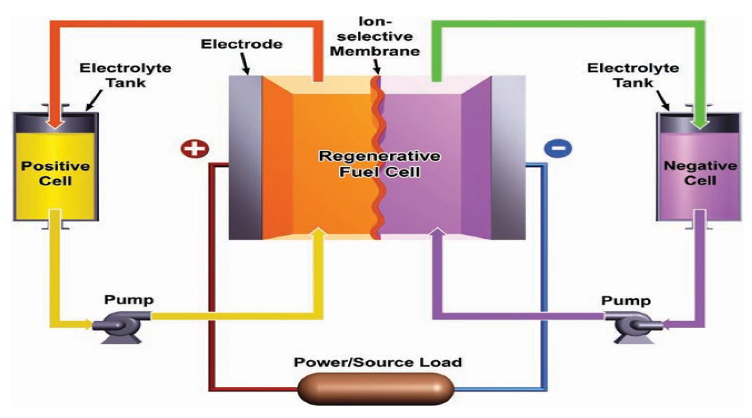
Figure 2.
Mechanism of vanadium (3.5+) electrolyte from VOSO4 material.
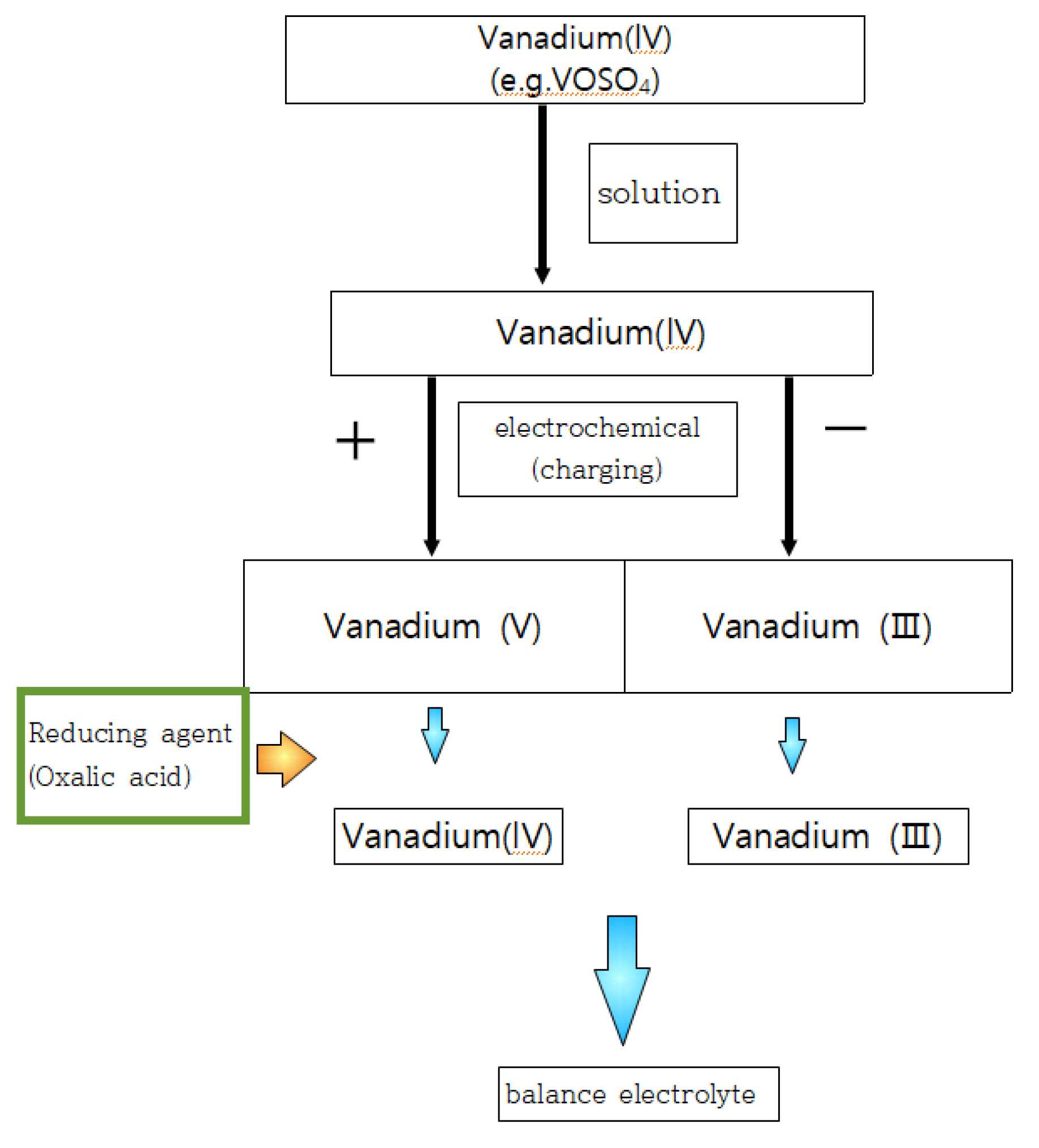
Figure 3.
Mechanism of vanadium (3.5+) electrolyte from V2O5 material.
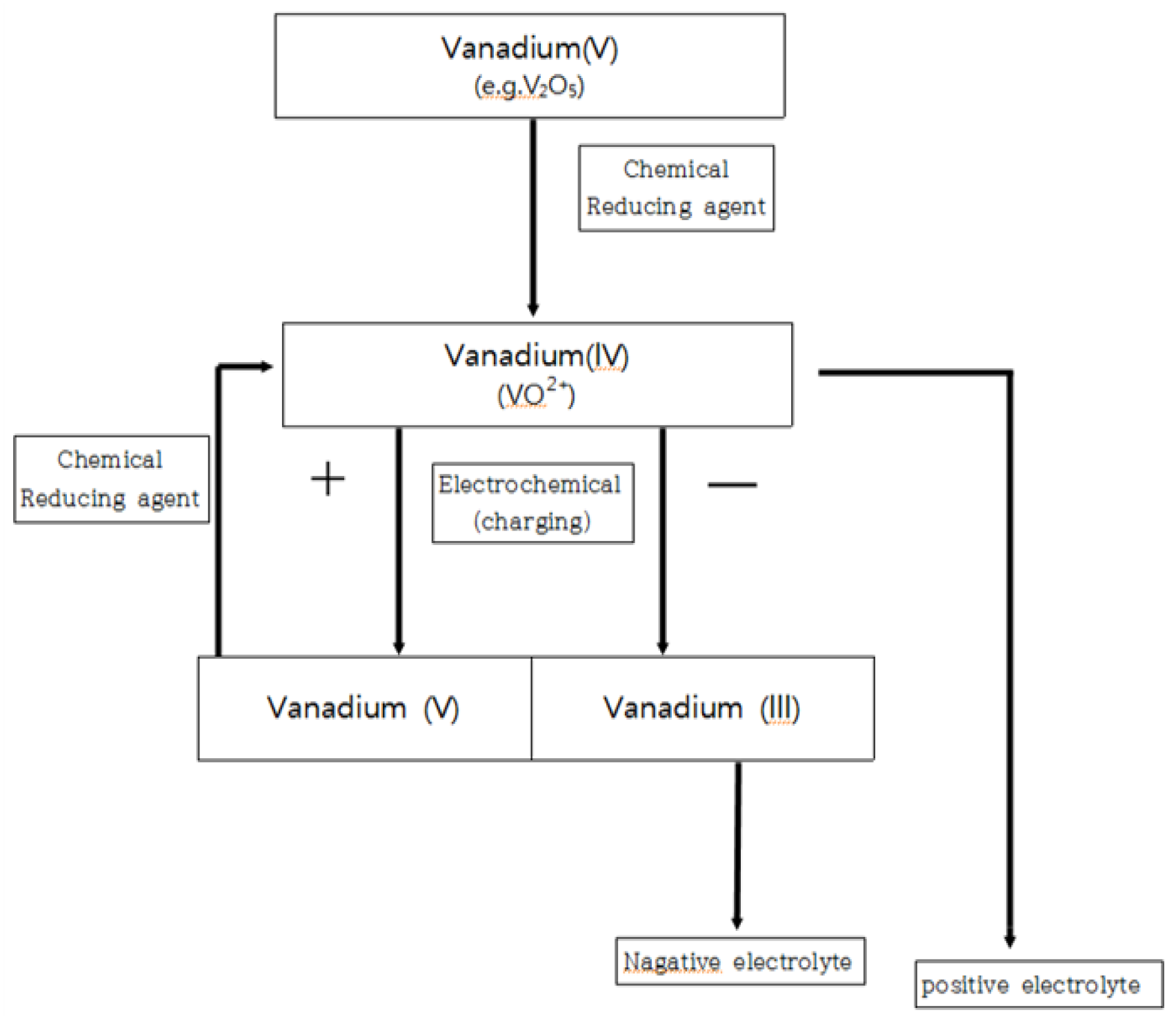
Figure 4.
Preparation process of vanadium (3.5+) by hydrothermal process.
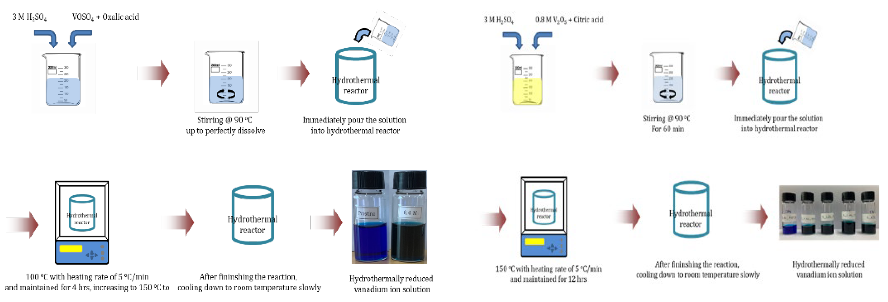
Figure 7.
UV-vis spectra of the vanadium(3.5+) electrolyte solution with different coconcentration of reducing agent. : (a) oxailc acid (1.6M, 3.2M,6.4M), (b) citric acid (0.8M~4.8M) (c) selected citric acid(0.8M,1.2M,1.6M, 2.0M).
Figure 7.
UV-vis spectra of the vanadium(3.5+) electrolyte solution with different coconcentration of reducing agent. : (a) oxailc acid (1.6M, 3.2M,6.4M), (b) citric acid (0.8M~4.8M) (c) selected citric acid(0.8M,1.2M,1.6M, 2.0M).
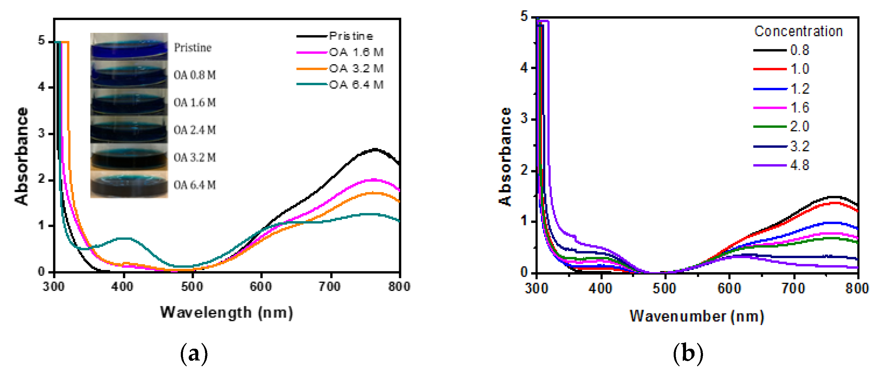
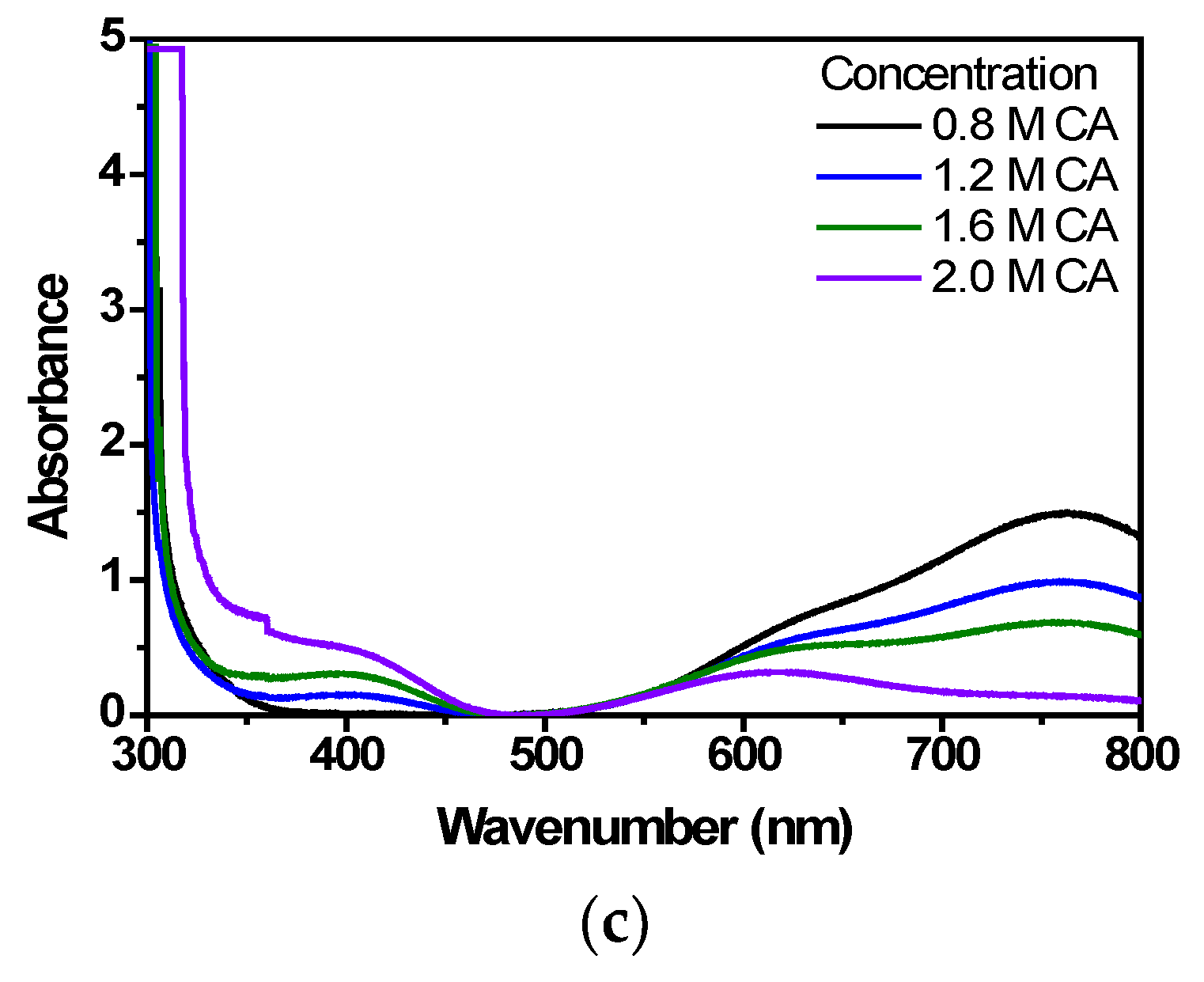
Figure 8.
The cyclic voltammograms of the electrolyte with different concentration of reducing agents. (a): citric acid (b): oxalic acid.
Figure 8.
The cyclic voltammograms of the electrolyte with different concentration of reducing agents. (a): citric acid (b): oxalic acid.
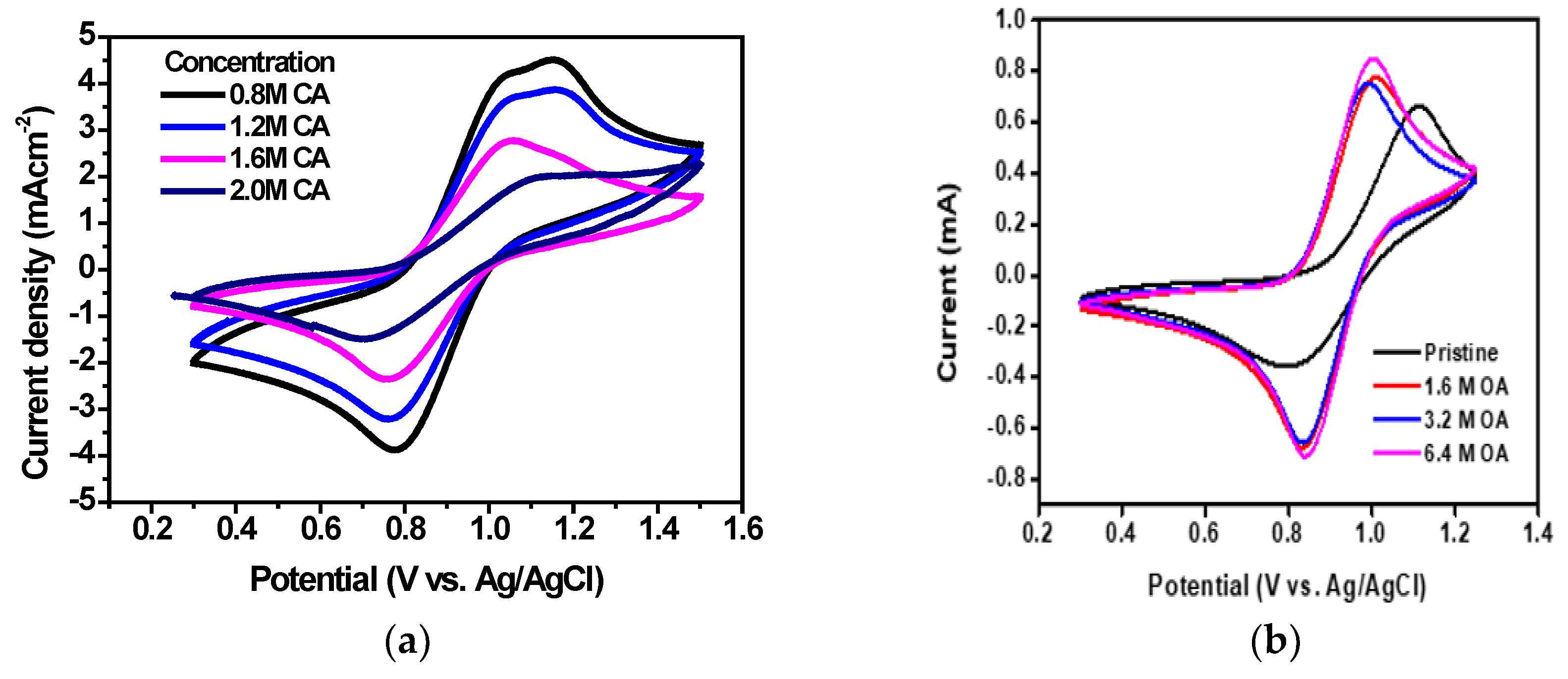
Figure 9.
Cyclic voltammograms of the electrolyte synthesized by HRR process (Black) and the conventional VOSO4 electrolyte (Red).
Figure 9.
Cyclic voltammograms of the electrolyte synthesized by HRR process (Black) and the conventional VOSO4 electrolyte (Red).
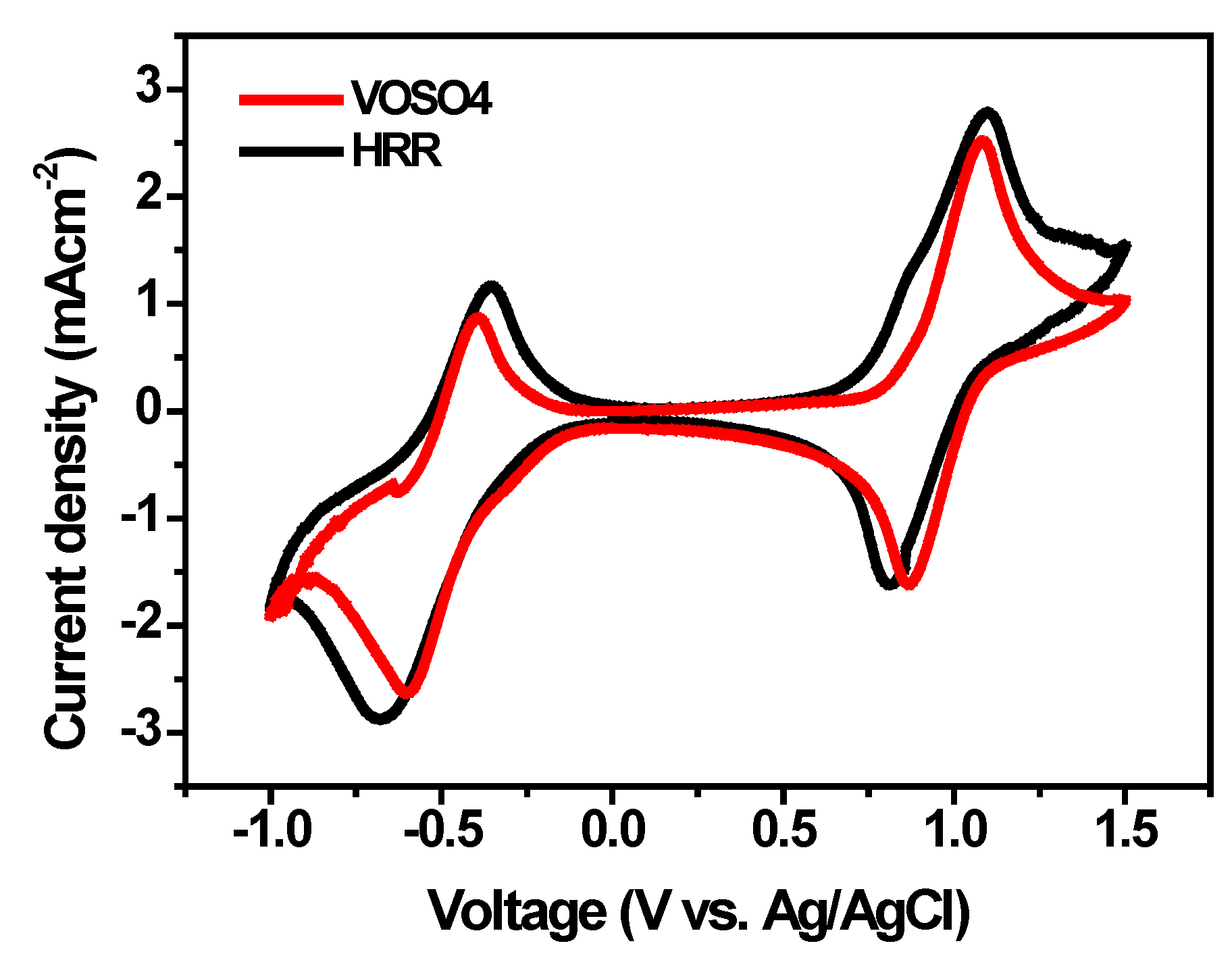
Figure 10.
Electrochemical behavior of VRFB using the prepared electrolyte: (a) 1.6M VOSO4 + 3M H2SO4 , (b) 0.8M V2O5 + 3M H2SO4 by HRR.
Figure 10.
Electrochemical behavior of VRFB using the prepared electrolyte: (a) 1.6M VOSO4 + 3M H2SO4 , (b) 0.8M V2O5 + 3M H2SO4 by HRR.
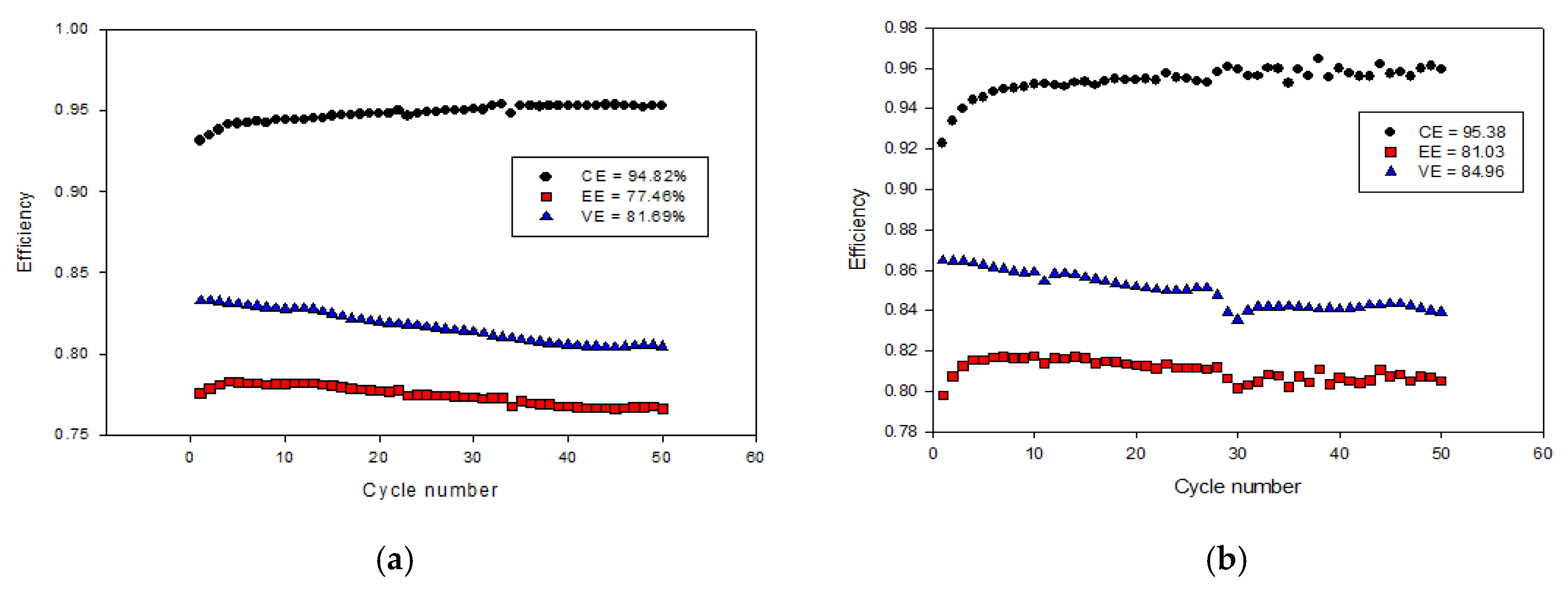

Table 1.
CV curves data of the electrolyte.
| Electrolyte |
Ipa Ipc Ipa/Ipc ΔE(V) |
Ipa Ipc Ipa/Ipc ΔE(V) |
|---|---|---|
| 1.6MVOSO4 +3MH2SO4 0.8MV2O5 +3MH2SO4by HRR |
2.28 1.10 2.07 0.36 2.00 0.85 2.35 0.20 |
1.62 2.81 0.57 0.39 1.60 1.90 0.84 0.45 |
Table 2.
Performance of VRFB cells.
| Electrolyte | CE | VE | EE |
|---|---|---|---|
| 1.6M VOSO4 + 3M H2SO4 0.8M V2O5 + 3M H2SO4 by HRR |
94.82 | 81.69 | 77.48 |
| 95.38 | 84.96 | 81.03 |
Disclaimer/Publisher’s Note: The statements, opinions and data contained in all publications are solely those of the individual author(s) and contributor(s) and not of MDPI and/or the editor(s). MDPI and/or the editor(s) disclaim responsibility for any injury to people or property resulting from any ideas, methods, instructions or products referred to in the content. |
© 2024 by the authors. Licensee MDPI, Basel, Switzerland. This article is an open access article distributed under the terms and conditions of the Creative Commons Attribution (CC BY) license (http://creativecommons.org/licenses/by/4.0/).
Copyright: This open access article is published under a Creative Commons CC BY 4.0 license, which permit the free download, distribution, and reuse, provided that the author and preprint are cited in any reuse.


