1. Introduction
Has one ever mentioned, what quality is actually about? Is it something that we see and looks good? Or is it soft and nice in touch? Or is it something that isn’t tangible and is invisible? If one ever heard such questions or wondered to find an answer, probably one also noticed that the answer is both – the tangible and the invisible. The invisible part is usually related to the manufacturer or solution provider but the tangible part is rather familiar for the end user. This paper will investigate the invisible part of the quality ensured by the process, mentioning the software development process designed and implemented in one project to engineer a GNSS-denied drone navigation system.
In this article, in
Section 2 and
Section 3, we will discuss the general process, the basic concepts and the objectives of any process. Then, in
Section 4 and
Section 5, we will explain how the software development process was designed on the example of a particular drone-related project. We will analyse an assumed environment, what problems have been solved and encountered and what can be done better to improve this process, in the future.
2. Process - fundamentals
A generic process is defined in [
11], as a
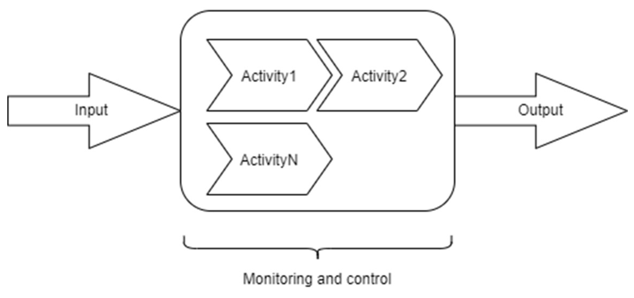
“set of interrelated or interacting activities, which transforms inputs into outputs”. Activities mentioned in the process definition, as defined in [
16] are a
“set of cohesive tasks of a process”. Going a little bit further and making the definition a little bit “elastic”, [
33] clearly states that this set of activities is designed to meet a given objective, what gives some freedom in understanding the idea of the process and leads to thinking about it as something we can create or change depending on our needs. Tailoring [
7,
8] is a process that allows the adaptation of standard or somehow defined processes to make them more suitable for the environment and needs.
Each process can be measured [
11,
28] and has a set of basic metrics that constitute values for process assessment. Regarding [
11] these are two metrics:
Effectiveness of process = ability to achieve desired results, and
Efficiency of process = Results achieved vs resources used.
But in contrast, the [
28] which is targeted to software product assurance in space engineering, defines the following two basic characteristics of a process utilised to develop and maintain software products in space applications:
Duration = how phases and tasks are being completed versus the planned schedule,
Effort = how much effort is consumed by the various phases and tasks compared to the plan.
We can see now, that metrics used to assess the process may vary and may be derived from constraints such as standards we must adhere to.
The general idea of a process is shown in
Figure 1.
Inputs and output to/from the process may be tangible and intangible [
11]. May it be any formal, or informal document, source code, executable software, materials, equipment, a piece of information, energy, and so on.
That is the general idea of a process. More about the benefits of the process approach, linking and implementing processes, etc. may be found in [
11]. It is worth mentioning that instead of the generic process, we can find a variety of process types forms. Each of them has its objectives, requirements, activities set and types of inputs and outputs. For example, project processes may be found in [
6,
7]
, processes related to software development in [
1,
3,
9,
16,
25,
26,
27], processes related to systems engineering in [
8,
12] and quality management/assurance in [
4] and [
28].
3. Why is process so important?
Martin Fowler, one of the authors of the AGILE manifesto [
18], in his article published in 2019, titled
“Is high quality software worth the cost?” [
17] defined an internal and external dimension of the quality. He mentioned that internal quality is something that the customer cannot see but is visible and experienced by developers. Also claimed, that high internal quality brings many more benefits than good quality, no matter that there is an initial slowdown at the beginning of the project. It is compensated later. Robert C. Martin in his book [
32] mentioned, that software is not only about writing source code and highlighted the big meaning of software architecture in ensuring software quality. In the foreword of quality standard [
4], it is stated explicitly that quality management of the software process is crucial to achieving software quality, and such process must be planned, controlled and improved. It is obligatory for the military drones’ software.
The Fowler’s text mentioned at the beginning of this section, leads to the conclusion, that process is the key to the success of a software development process. Even, in 1992 NASA wrote in [
1], that one of the keys to success is to develop and adhere to the Software Development Plan (SDP). Software Development Plan [
1,
15,
25,
26,
29] is a document that contains a plan for developing software in the project. In very general words, it describes the development environment and development activities and its relationship – process, etc. Simply speaking – it addresses the plan for software development and the process description as the main part of this plan.
Another confirmation of process meaning for the project can be found in [
30]. One of the leading indicators in systems engineering is
“Process compliance trends”. The explanation given to this indicator, clearly states that poor or inconsistent systems engineering processes or weak adherence to defined processes increase project risk.
One more proof for the above claim is described in the AGILE PM handbook [
6] and it says clearly that quality corresponds to both, the range of features delivered and the technical quality of what is delivered. This is all sealed with the statement that the process is imperative to achieve quality.
We believe this is enough to prove the importance of the process.Now let’s look closer at the software development process in the GNSS denied navigation system development project.
4. Software development process
First, let’s explain what the software development process means from the system engineering and software engineering points of view.
The software development process and its activities are in general documented in [
3,
16]. But, there are some more specialised processes targeted and tailored to the specific needs of a given domain. For instance, considerations regarding the software development process for aviation are documented in [
2,
9], and should be used for drones with a maximum take-off weight between 150 and 20 000 kg that are intended to operate in non-segregated airspace [
50]. Considerations for space applications can be found in [
1,
26,
27,
28].
We can summarise that any software development process usually, concerns the following aspects of software engineering [
27]:
requirements definition;
design;
production (implementation);
verification and validation;
transfer (installation);
operation and maintenance (utilisation);
Sometimes, other aspects are also considered during the software development process. For instance [
9]: software planning, certification, integration or disposal [
16]. They are the key aspects of the certified drones applied in the civil and military areas. A set of processes like quality management or configuration management [
8] are also taken into account during software development. How much support processes are incorporated into the software development process chosen or designed for the project, depends on the need (contract regulations, company rules, etc.) and tailoring [
7,
8,
16] associated with it, though. Knowledge areas like quality management and assurance [
16], version, configuration or change management [
3,
4,
5], are also in the scope of software engineering [
3] and thus, shall not be omitted while considering a software development process. They are crucial to achieving acceptable quality of product or service [
4,
8,
16], and then for certifying the software and drone.
There is one thing that needs to be highlighted, before further discussion. The designed and described process analysed in this article is not a standard adaptive process but it is tailored to specific needs and environment. The “end user” of that software is an autonomous drone, certified-ready, capable of operating for hours in a GNSS-denied environment.
This was an AGILE [
6,
7,
12,
18,
19] based process, driven by three scrum pillars [
13], as they were considered valuable and helpful in the target environment. The main factors that dictated the implementation of identified process activities and had a big impact on how the process looks, were cumulated around:
current work style,
company internal regulations,
team experience and attitude to adhering to established processes,
different locations of teams (teams were not working in one location),
research character of a project that was burdened with a dose of uncertainty regarding the direction of understanding the problem - product development started from Technology Readiness Level 4 (TRL 4) [
42] and was targeted to achieve Technology Readiness Level 6 (TRL 6),
knowledge maturation regarding the problem to be solved and possible solutions that may significantly change current ideas and draft solutions – that, may generate frequent changes,
plans regarding project continuation in the next years and development of the product to a higher Technology Readiness Level [
42].
More about the presented and discussed project may be found in [
43].
4.1. Aspects considered in the process for drones’ GNSS denied navigation system development project
There were many aspects and issues to consider in the drone-dedicated software development process set up for the example project. Those were:
general, standard development approach to use as a base for tailoring;
software requirements – elicitation/decomposition/definition;
quality characteristics of desired product;
software design;
software implementation;
software verification and testing;
standards to consider;
process metrics;
tools that support activities;
transforming software requirements to “issues” [
23] or tasks.
ensuring the product is complete by incorporating traceability;
defects and errors management;
version and release management;
The drone-dedicated software development process and its details were addressed in the Software Development Plan (SDP) [
1,
15,
25,
26,
29]. It was prepared before the development activities began, yet, in the project planning phase [
7], to make sure to reduce the overall risk associated with the software development activities. Now we will analyse the software development process in detail.
4.2. Software development process and activities in drones’ GN SS denied navigation system development project
After considering, many factors like requirements certainty, scope stability, ease of change, etc., that help choose the project approach mentioned in [
7], the decision was made to choose an adaptive approach over hybrid or plan-driven (sometimes called “predictive”) [
3,
6,
7,
12,
13,
19] for software development with some modifications that will be addressed further in this section. According to the paper’s title, we will discuss the process for drone-dedicated software development only, not for the entire project. The approach for the entire project is the subject of a Project Management Plan (PMP) or Project Plan [
14] and is out of the scope of this paper.
Regarding the software development process for drones. Even though the software requirements [
2,
16] and scope were stable and were derived from the system level [
8], the degree of innovation was high. Therefore, there should be a “place” left for changes as the developers' knowledge matures with the product development and as the software is the main and key part of the product - drone. The development team size was also considered, and it was below 10, which makes it good for an adaptive approach [
7,
13]. The objective of the software development process was to reduce the risk associated with the development activities [
30] and to built-in resilience by providing an ability to adapt and respond in a short time [
7] to uncertainty related to high product innovation and new process approach that the team needed to face with.
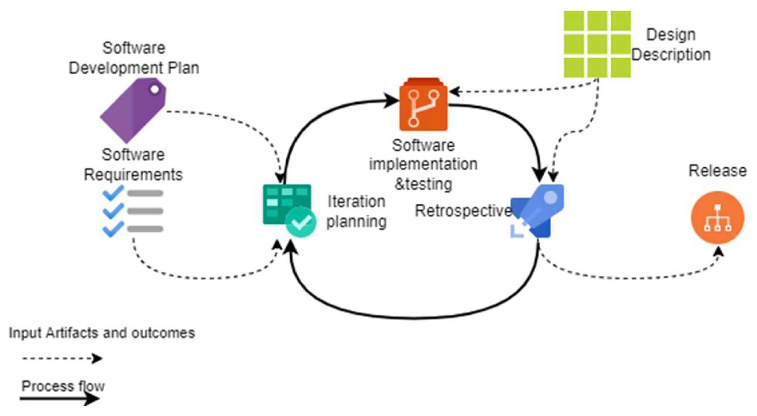
The general view of the software development process for drones implemented in the project is shown in
Figure 2.
The process is focused on three basic activities: iteration planning, software implementation and testing (coding and tests) and retrospective [
6,
13] – a review and conclusion. Input data needed to perform the process activities are the software development plan (SDP), software requirements and design descriptions of components which were developed during the project as software solutions. The outcome of the process is software release.
The process, in general, is an adaptive one, based on three important scrum pillars, which are: transparency, inspection and adaptation [
13]. Those pillars form the basis for every activity within this process.
4.2.1. Preparation activity
Software requirements [
2], and [
16] taken as input to the process are already prepared and somehow stable (at least 75% of the expected number) before the software development process activities begin. That gives a better view of the development scope and allows us to better plan tasks and support ensuring product completeness by providing traceability (task to requirements and vice-versa). Software requirements are then transformed into “issues” [
7,
23], which represent tasks to be completed. The name “issue”, corresponds to the term used in a tool that was chosen to support the example process and will be mentioned later.
Functional requirements [
2,
3,
5,
8], are first represented by issues whose names correspond to the name of a function represented by such requirement and are given a special label, that marks this issue as a function like “function 1, function 2, function n”. Labels are also a consequence of a chosen tool. Each issue that has a requirement as a parent is giving a special link to the issue representing a function, to ease the tracking of function development progress. In fact, in software development, we provide functions but performance requirements [
8] are a special kind of quality requirements that correspond to the quality of these functions that deal with values like time, volume, frequency, etc. The number of functions we need to implement in software depends on how many functional requirements we have allocated to the software. The non-functional requirements tell us about the quality [
8] and degree of complexity of implementing such functions [
39]. Non-functional requirements like quality requirements [
5] may have their source, for example, in specialty engineering areas [
8] like safety engineering, reliability engineering, etc. or in quality models and quality characteristics related to those models like ones defined in [
10] or [
28].
[
28] clearly defines “quality model” as a set of characteristics and relationships between them. It is used as a basis for specifying quality requirements and evaluating quality.
Key software quality characteristics identified for software developed during the example project were based on [
10] and are mainly:
functional completeness and correctness (from the functional suitability group),
time behaviour and resource utilisation (from the performance efficiency group),
analysability, modifiability and testability (from maintainability group).
Each characteristic, however, should be understood in terms of a product under development and its context [
5] or intended future use. It should be transformed into requirements and then reflected in system/software design. This is a common practice to use some pre-defined patterns that support different characteristics related to software architecture as mentioned in [
38]. The process described in this paper goes further. It is designed to facilitate ensuring that these characteristics are reflected in the final product.
This is a useful consequence of the three valuable scrum pillars mentioned in [
13]. The process supports achieving these characteristics by providing means of facilitating, especially transparency and inspection. Adaptation is achieved by self-concluding the results and mainly takes place in a retrospective activity described further. Means provided by the process to support product quality in terms of mentioned quality characteristics are:
task traceability to requirements and vice versa (to support product functional completeness concerning software requirements specification),
deriving task acceptance criteria from parent requirement (to support performance efficiency assessment and make sure that the final product reflects its specification, what support also a partial software verification [
8,
34])
provide unique identifiers related to software products [
16], their version, branch, iteration and documentation set to support error and defects management, project completion and to ease analysis while looking for errors or estimating the impact of proposed or required changes,
bounding branch and task identifier to a specific part of source code developed during iteration to support analysability, which limits the inspection only to the specific part of the source code.
unifying work style and language usage – modifiability and analysability, in part not dependent on system/software design, are supported by the process itself. Addressing coding standards [
1,
28] like [
32] should ensure that everyone in the team “speaks the same language” and can support product development or modifications of source code prepared by somebody else from the team without having doubts about the meaning of variables and so on.
Functional requirements may be represented as use case if there is an interaction with an actor [
21,
22,
40], user story [
6,
35,
36,
41] or traditional requirement [
5,
41]. User stories may contain some additional information about quality or acceptance criteria and are prepared following INVEST rules [
6], [
35] rather than quality criteria for traditional requirements [
2,
3,
4,
5,
8,
34,
41]. They shall be transformed, decomposed to other forms and supported by additional information to facilitate analysis or traceability as they may not provide full and detailed specifications [
41]. Some more discussion about the meaning of requirements in the project can be found in [
17].
After this “one-time” activity (assuming all software requirements are prepared before the process starts, otherwise this activity is repeated for the rest of the requirements) the list of tasks which constitute a product backlog [
12,
13] is prepared and iteration planning may now begin.
Although the process assumed requirements are stable before entering the first activity in the process, the process may trigger a need to return and refine requirements on every level as the knowledge about the problem and possible solutions mature during the project (as a tool of “adaptation”[
13]). This is not marked explicitly in the software development process itself, as this is rather the matter for the configuration/change management process [
3,
4,
5,
8,
9,
37].
A software development plan is one of the inputs needed by the process to facilitate giving some additional (of little importance for this article matter) parameters/data to tasks selected in iteration planning. It is to facilitate traceability, task management, results reference (for example a reference to a file containing a comprehensive report or other information needed to complete the task, etc.) and tracking relationships between tasks (if exist).
4.2.2. Iteration planning
The duration of iterations in an example project was two weeks. This is enough time to see progress but not to allow the work to go in the wrong direction so far. To set up iteration duration, the company work style and the need for project and software development monitoring were considered. Each task is then created in a way that allows work to be done in these intervals. The tasks too big to be implemented in two weeks were split into smaller tasks. After preparing a product backlog that way, there is a better possibility to estimate the overall software development duration in iterations or weeks. This approach also facilitates progress monitoring with a burn down chart [
12] to correct estimates and determine the real velocity of the team in implementing issues. The velocity is determined by measuring the number of issues closed per iteration and is used to adjust the number of issues to be implemented in the following iterations. Productivity can be measured by dividing velocity by number of team members [
12].
During iteration planning, each team member responsible for source code development chooses tasks to do during the iteration. That way, the team creates an iteration backlog. The number of tasks chosen by one person in the current iteration depends on historical data (if there are some already collected from previous iterations), and the estimated time needed to complete the task. Although tasks were prepared to fit, to two weeks duration, some of them may be much simpler to complete and may take for example a day. Everything depends on the parent requirement complexity and understanding of the requirement by the developer during transformation. A few initial iterations may not be planned optimally, due to a lack of historical data regarding team (or person) velocity. This will be unveiled after a few iterations and corrections.
After selection, each selected task is given its acceptance criteria [
5,
35,
36] or definition of done [
13] (no matter the name) to facilitate effort assessment and provide a common understanding of what is the limit of the task and what results allow the task to be marked as completed. This is done to facilitate transparency, inspection and adaptation [
13] regarding achieved results and related thoughts/conclusions.
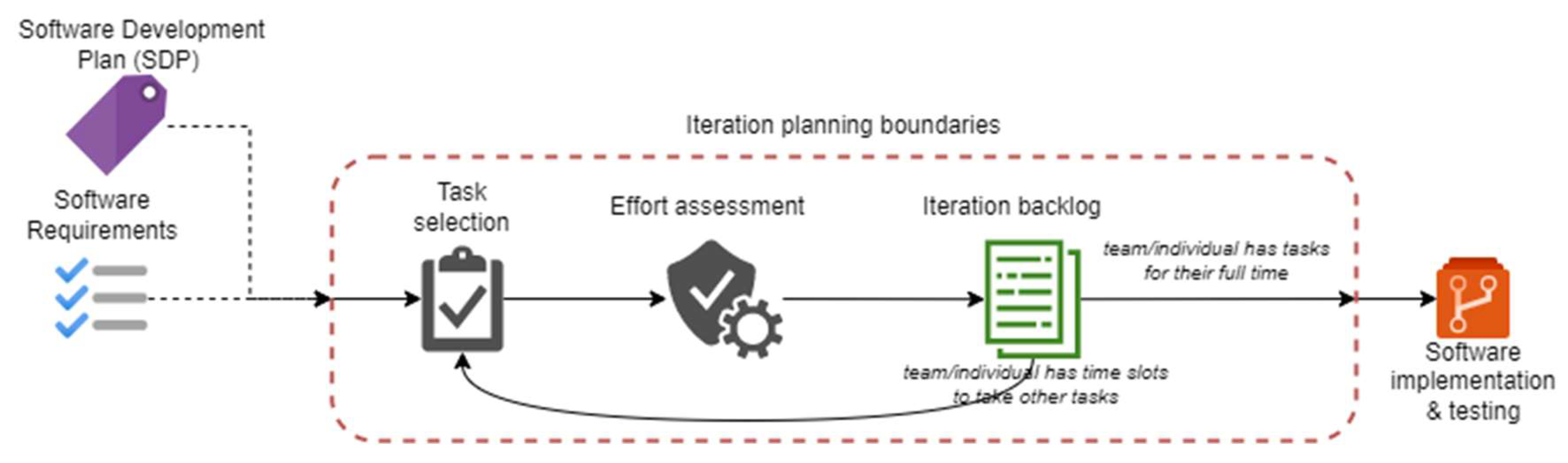
The number of tasks selected by individual team members depends on the time the member declared for this iteration, the level of complexity of the task and the developer’s skills. The time available for the current iteration is determined before selecting tasks. Full time expressed in hours by iteration depends on the work week – if it’s shorter, the overall time is also shorter, and the engagement of individuals in other projects.
The iteration backlog is then the output artefact that is an entry data for software implementation and testing activity.
A “zoom-in” into iteration planning activity is shown in
Figure 3.
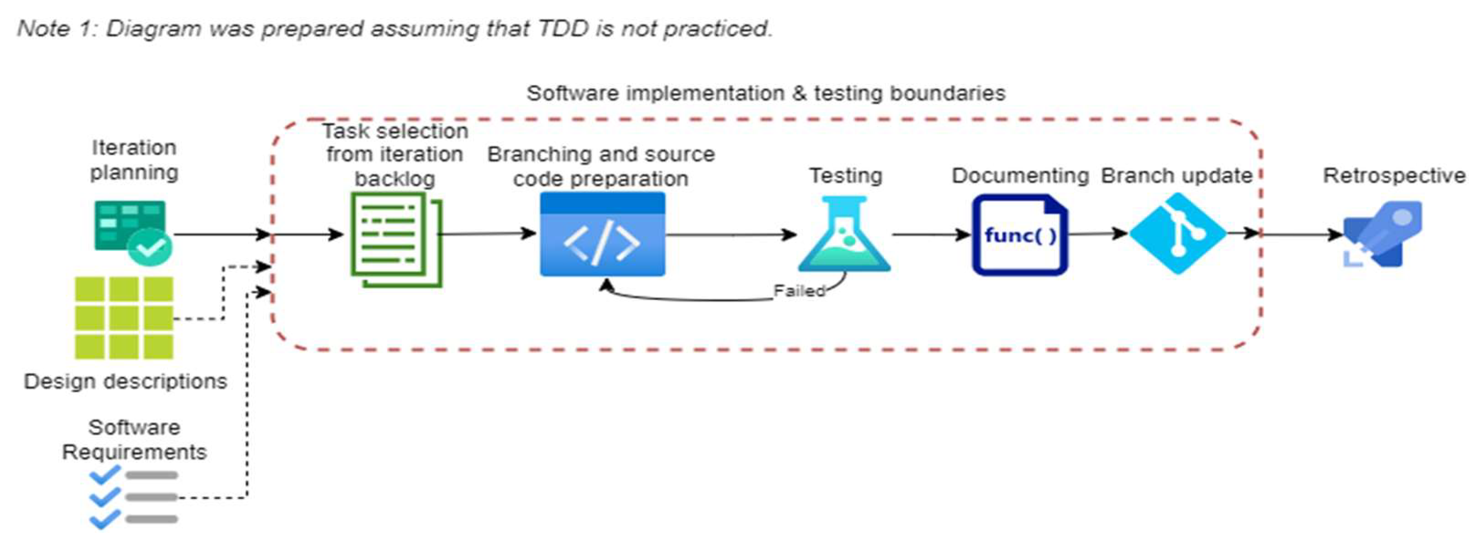
4.2.3. Software implementation and testing
Software implementation and testing activity is essential during the transformation from specification and design into a tangible thing. It is composed of a few tasks as shown in
Figure 4.
After the activity starts, each developer chooses a task from the iteration backlog, to implement. To minimise the risk of errors implemented in the source code, the Software Development Plan (SDP) assumed that there should be only one task under implementation at a time for an individual. This depends on how the tasks were created and if there are no related tasks that should be at least partially done before, to enable test for the current task. Each developer follows the path on his own and independently from others. Fortunately, in the example project, teams were divided in a way that one team was responsible for one software component [
28], for example, one software application.
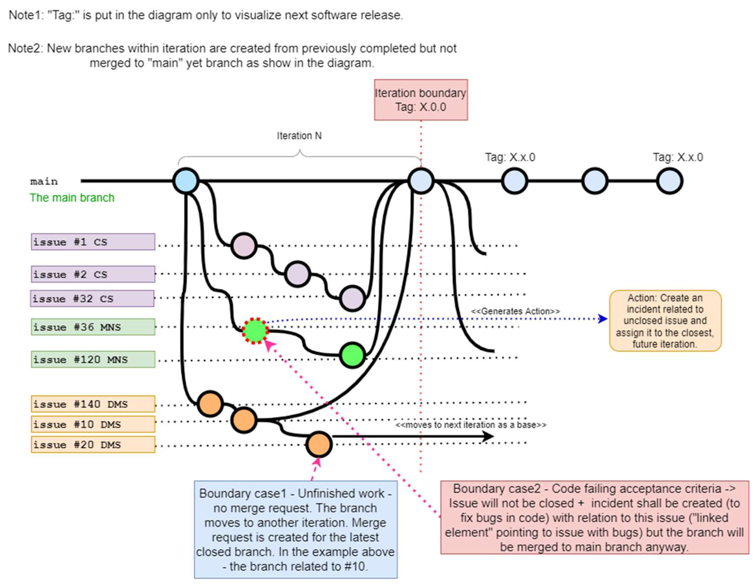
After the developer decides what task from the iteration backlog to implement first, the branch [
24] should be created. Branches are related to the git version control tool (
https://www.git-scm.com/). The general idea of branch management in the project is shown in
Figure 5.
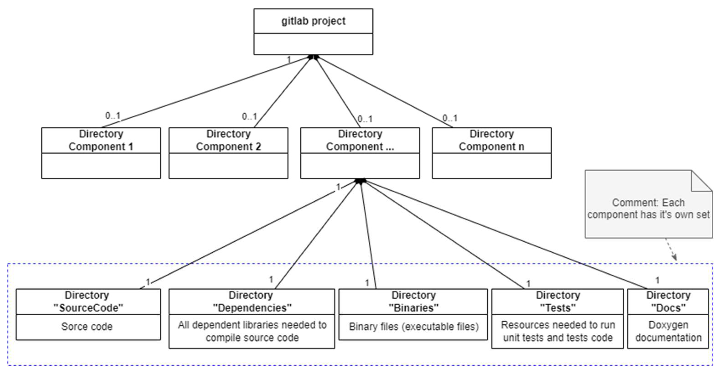
There is one main branch foreseen to store the source code, which was accepted in the retrospective after each iteration (next activity in the process). Each developer responsible for the chosen task creates a new branch from the main branch at the beginning of the iteration. Before the first iteration, the main branch stores an empty repository structure. Each developer needs to clone and organise a project in the Integrated Development Environment (IDE) of choice to fit the repository structure. The repository structure is shown in
Figure 6.
After preparing the project in IDE, each developer must create a branch with an identifier which was designed for error or defect tracking and task management. Identifier details have no meaning for this article, that’s why it will not be discussed.
Each branch corresponds to a different issue. To facilitate repository and tasks/issues management the GitLab tool (
https://about.gitlab.com/) was selected. Selection criteria are out of the scope of this paper as the tool is only a means to facilitate activities but is not, and should not be the core of the process. Tool selection criteria were also dependent on company factors as well. In the GitLab, issues are marked with “#” that is followed by a number pointing to a particular, unique issue number. Corresponding to
Figure 5, “issue #1 CS” and similar text in rectangles on the left, means different branches corresponding to the different issues. “CS”, “MNS”, and “DMS” that appear in this paper, are shortcuts of the full names of software components to be developed during the example project and have no meaning for this article.
After having work done, or at the end of the iteration (during retrospective described further), the last created and completed branch (that also means that the corresponding task is completed) is merged to the main branch that stores, up-to-date and working code. Splitting teams to be responsible for their component and organising repository as shown in
Figure 6, allowed to minimise the number of merge conflicts depending on team size and internal communication. If the task is not completed or its results don’t fit acceptance criteria as pointed out in the iteration planning activity, the branch is recognised as unsuccessful and goes to another iteration. In such cases, the last successful branch is merged with the main branch to be sure that only the working code is stored. Before a developer can recognise source code as working code that meets acceptance criteria, unit tests [
1,
28,
35,
36] need to be run. For the first time, the process was in its draft release, Test Driven Development (TDD) [
20] was considered but finally rejected due to the current teamwork style and many other new challenges that the team needed to face. It required some new habits and energy, to get used to thinking about testing code that already doesn’t exist yet. There are some benefits of such an approach as addressed in [
19] and it should be considered when we need to have the “courage” to implement changes in the code.
Having tasks traced to requirements and having acceptance criteria derived from parent requirement, partial software verification testing [
5,
8,
34] at the component level [
8] is executed simultaneously with unit testing.
Regarding the repository structure in
Figure 6, the diagram is simplified, which makes it easier to understand for people not familiar with SySML [
22] or UML [
21]. In the diagram, the composition relationship [
21,
22] is shown (an arrow with a filled diamond on one end). It means that a directory pointed by the diamond is composed of directories on another end. 0..1 or 1 that are visible on the arrow ends are the multiplicities [
21,
22] which point that one upper-level directory can be composed from 0 to 1 directory or exactly 1 lower-level directory (subdirectory). Describing the diagram, we can say that the “gitlab project” directory can have from 0 to 1 subdirectories named Component 1, Component 2, etc. The Component 1, 2.., etc. corresponds to the name of the software component that is to be developed during the project. That name should be replaced with the name of the component that the particular team is responsible for.
To facilitate further product development and modifications by different teams or individuals, coding standards like [
31] were addressed in the Software Development Plan (SDP). The source code was documented using the doxygen (
https://doxygen.nl/) file generator and doxygen comments in the code to allow automatic document generation.
4.2.4. Retrospective meetings
Retrospective [
7,
13] meetings take place after each iteration. There are frequent meetings performed on the last day of ongoing iteration. Its goal is to conclude the job done during iteration, to check together achieved results from their acceptance criteria or definition defined earlier point of view and to talk about the future improvement of the process or technical performance of the product. Additionally, the meeting helps to identify, gaps and obstacles that stop us from doing something (like IT environment limitations, missing tolls, etc.), and address proposed changes. The goal of retrospective meetings in the drone software development process is to achieve inspection and adaptation.
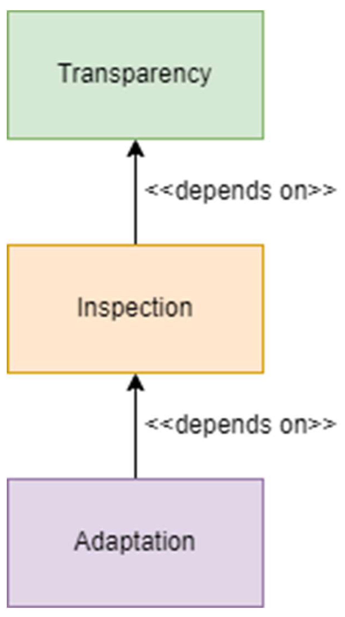
As mentioned in [
13], we need to be transparent to make sure all team members understand expectations, goals, the process we are going through, and their role in this “journey”. Then we can inspect. The more transparency, the better for inspection. If we inspect, we can conclude, if we conclude we can improve and learn, then we adapt. There is no adaptation without transparency and inspection.
The relationship between those pillars is visualised in
Figure 7.
The relationships, clearly pointed out that transparency is the key value to achieving the other two values. The process defined in that paper supports transparency and partly, inspection, which was already described.
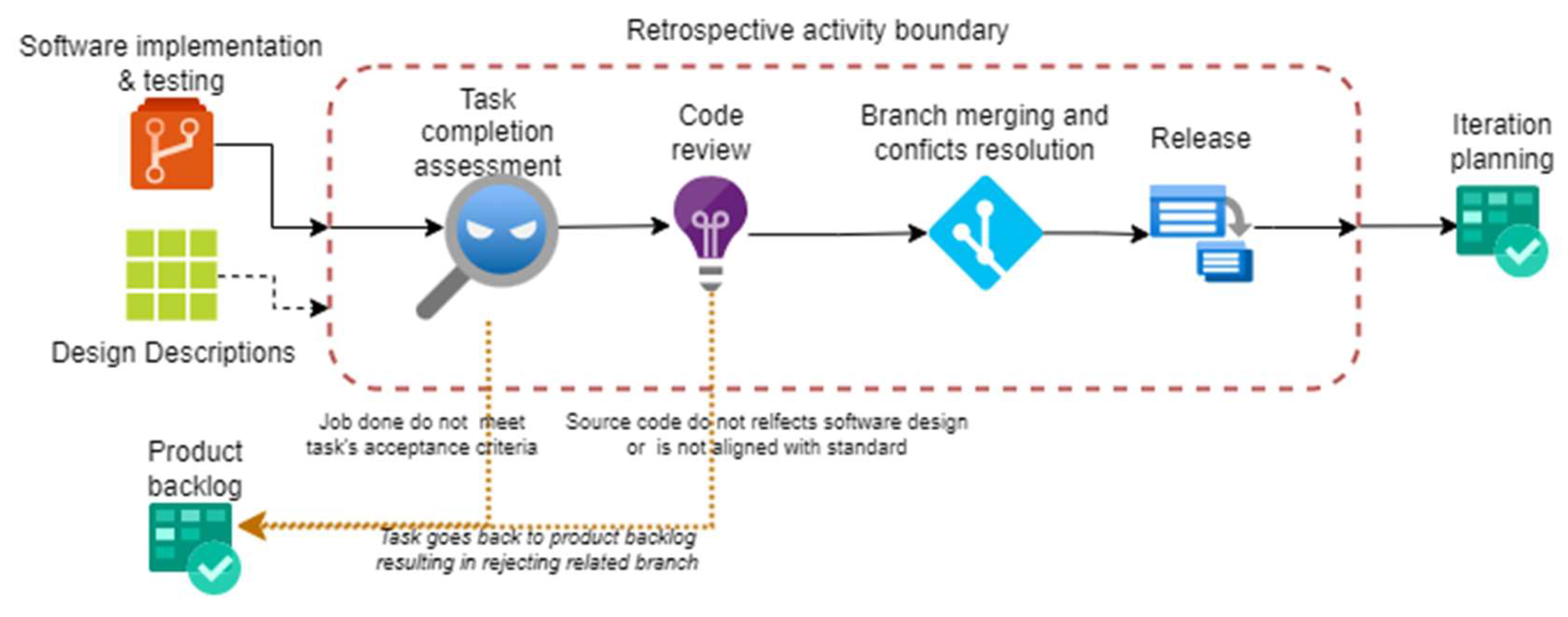
Retrospective meetings, except for talking with the team, concluding together, discussing and resolving or addressing problems are conducted as shown in
Figure 8.
The first task in the activity is task completion assessment. This task is based on an interview with the developer responsible for the task and mutual verification of achieved results.
General acceptance criteria for every task, no matter if there are some derived from parent requirement or not, are:
- -
code is compiling and working,
- -
code sticks to coding standards,
- -
tests were performed on the code and passed,
- -
code is documented with doxygen and the updated document is placed in a dedicated subdirectory in the repository,
- -
code is aligned with software design – if not – the design was already updated before finishing a task.
If the job done within the task meets its acceptance criteria the task is assumed to be completed and marked as done. Actually, for the overall endeavour, every task does not correspond only to requirements and doesn’t finish with a piece of source code being prepared. Some tasks may be dependent on analysis that needs to be done before source code development or may be related to environment and hardware resource preparation. These tasks may have additional acceptance criteria defined while taking the task to the iteration backlog. Such tasks do not generate a new branch but may be bound to another task that ends up with source code to facilitate relationships, work completion and error tracking. If any task is assessed as not meeting the acceptance criteria, it goes to the product backlog. It is preferred to be finished in the very next iteration if possible (sometimes, to complete the task we need to do other tasks first, but this relationship is invisible at a glance). In
Figure 8, a task completion assessment is divided into two parts, task completion assessment and code review, to mark that there are two kinds of assessments done during this task. If a task is not related to a source code, the code review is not applied to it. The process assumes that the number of such tasks is limited only to a few. That’s why it isn’t highlighted in
Figure 8 with a separate path going around code review and other tasks in the activity.
If a task is completed, branches related to the development of other components may be merged into the main branch. If any conflict appears during the merge this should be resolved by the developer or repository manager as fast as possible to enable the branch management strategy realisation, as shown in
Figure 5. If branches are merged successfully, a drone software release with dedicated version tags is prepared that contains a working or accepted piece of software products [
16] (code, related documents, etc.). It may constitute a return point or be passed to further tests if eligible.
5. Problems related to the proposed solution
There is no rose without thorns. Although the process was designed to support many aspects of drone software development in the target environment and for specific needs, the solution needs further improvement based on data and conclusions collected after the first phase of the project. During the drone software development process, we encountered some problems or obstacles that influenced overall process performance and made it difficult to follow. Problems were mainly related to:
New task being created “on the fly” in an advanced phase of development.As the team consisted of software developers only, it was difficult to foresee and prepare correct and stable software requirements before development started. Of course, uncertainty is the source of changes. Uncertainty is related to the project goal and other factors described earlier in the paper. But there is still a part of functionality and quality we can identify and freeze earlier to minimise the risk and number of changes. This may be pointed out by project objectives [
7,
45], and Key Performance Indicators (KPI) related to it [
7,
12] or Measures of Effectiveness (MOE) [
8,
46] or Measures of Suitability (MOS) [
8,
46]. As claimed in [
48] developers often fall into an “implementation trap” [
48] focusing on solution space rather than problem space, so requirements prepared by such individuals caught in such trap are not abstract (free of implementation) [
47] and they need to be changed later.
New tasks (incidents) being created due to failed tests of a given software release.This problem is related to handling new tasks (incident type in our version of GitLab), that are created due to failed tests performed on a given software release, not failed during unit tests performed by the developer himself. The hard thing is how to address changes in ongoing iteration if it appears that correction is crucial to not delay other tests planned for a given time and not to break the currently opened branch to avoid merge conflicts.
Applied branching strategy requires a discipline to be followed by individual developers. Not following this way, creates conflicts, and missing or overwriting code problems.
Choosing tasks to complete in “free order”, may have an impact on the test plan and test schedule slips. If the test plan for example foresees that function A or function B is a subject of a particular test run [
36], this may require removing that function from the run or changing the schedule if at least one task corresponding to a function (as described in
Section 4.2.1 Preparation activity) may not be completed on time. To avoid this, the process requires providing a little bit of “control” in deciding what tasks will be done in the current iteration.
These are the problems, that were encountered during the project performed in a specific environment while developing software for the drone navigation system. Probably, other p roblems may be revealed in different environments, and some may disappear or their impact may be negligible.
6. Conclusions
In the article, the general idea of a process and its importance for the project was addressed. The explanation of the drone software development process was presented and its implementation in the particular environment was comprehensively addressed. The good and bad sides of the proposed approach were discussed.
Concluding all the given knowledge, stated in
Section 3, and experience described in
Section 4, we may confirm that the process is imperative to achieve or enable quality. It addresses many issues and aspects which are usually forgotten and helps to provide resilience to surprises before they happen. The drone software development process also supports the development team in monitoring and controlling work and work items. It helps to improve developers’ activities by providing the means of monitoring and understanding relationships and consequences of activities or tasks. Also, the certification of such way developed software is easier and takes less time for testing and verification.
These are the reasons why it is worth establishing a process and adhering to it.
References
- NASA Goddard Space Flight Center Greenbelt, Maryland 20771. “Recommended Approach to Software Development. Revision 3”. Software engineering laboratory series (SEL-81-305). June 1992.
- Lenna Rierson. “Developing Safety-Critical Software A Practical Guide for Aviation Software and DO-178C Compliance”. Version Date: 20121016. Edi. CRC Press Taylor & Francis Group. ISBN: 978-1-4398-1368-3.
- Ian Sommerville .“Inżynieria Oprogramowania” wydanie X. Edi. PWN 2020. ISBN 978-83-01-21259-9.
- AQAP 2210, Wydanie A, wersja 2. „Wymagania uzupełniające NATO do AQAP-2110 i AQAP-2310 dotyczące zapewnienia jakości oprogramowania”. September 2015.
- M. Glinz, H. van Loenhoud, S. Staal, S. Bühne “IREB Handbook for the CPRE Foundation Level according to the IREB Standard”, version 1.0.0, November 2020.
- AGILE Business Consortium „AgilePM Agile project management handbook v2. Wydanie polskie”. ISBN 9781910961049.
- Project Management Institute. “PMBOK Guide seventh edition and the standard for project management.” ANSI/PMI 99-001-2021, ISBN 9781628256642.
- INCOSE. „Systems Engineering Handbook A Guide for Systems Engineering Life Cycle Processes and Activities”. INCOSE-TP-2003-002-04, 2015. ISBN: 9781118999400.
- RTCA-DO-178C “Software Considerations in Airborne Systems and Equipment Certification”. December 13, 2011.
- ISO/IEC 25010:2011” Systems and software quality requirements and evaluation (SQuaRE). Software quality models.”.
- ISO 9000 Introduction and Support Package: “Guidance on the Concept and Use of the Process Approach for Management Systems”. ISO/TC 176/SC 2/N 544R3.
- B.P.Douglass „Agile Model-Based Systems Engineering Cookbook”. Second edition. Edi. Pact. ISBN 978-1-80323-582-0.
- K. Schwaber, J. Sutherland “The Scrum Guide. The definitive guide to scrum: The rules of the game. November 2020.
- Project Plans. https://www.projectmanager.com/guides/project-planning, accessed 15.05.2024.
- Software Development Plan. https://acqnotes.com/acqnote/careerfields/software-development-plan accessed 15.05.2024.
- ISO/IEC 12207-2008 “Systems and software engineering – software lifecycle processes”. Second edition 2008-02-01.
- M. Fowler. „Is high quality software worth the cost?”. 29 May 2019. Article available at: https://martinfowler.com/articles/is-quality-worth-cost.html, accessed 15.05.2024.
- Agile manifesto. Manifesto for agile software development. Available at: https://agilemanifesto.org/ accessed 10.05.2024.
- Robert C. Martin. „Czysty Agile. Powrót do podstaw”. Helion 2020. ISBN: 978-83-283-6304-5.
- Kent Beck „TDD. Sztuka tworzenia dobrego kodu”. Helion 2014, 2020. ISBN: 978-83-283-6572-8.
- S. Wrycza, B. Marcinkowski, K. Wyrzykowski, „Język UML 2.0 w modelowaniu systemów informatycznych”. Helion 2005. ISBN: 83-7361-892-9.
- L. Delligatti „SysML Distilled A brief guide to the systems modelling language”. Addison-Wesley. ISBN-13: 978-0-321-92786-6.
- Explanation of „issue - gitlab”. https://docs.gitlab.com/ee/user/project/issues/ .
- Git branching – Branches in a nutshell. https://git-scm.com/book/en/v2/Git-Branching-Branches-in-a-Nutshell.
- MIL-STD-498 „Software development and documentation”. US Department of Defense. 5 December 1994.
- ECSS-E-HB-40A “Space engineering. Software engineering handbook”. 11 December 2013.
- ECSS-E-ST-40C “Space engineering. Software”. 6 March 2009.
- ECSS-Q-ST-80C, Rev.1. „Space product assurance. Software product assurance”. 15 February 2017.
- Defense Acquisition Guidebook. 16 September 2013.
- INCOSE Technical Product Number: INCOSE-TP-2005-001-03. “Systems Engineering Leading Indicators Guide”. Version 2.0, January 29, 2010.
- L. Jun, W. Shoan. NASA. “C++ coding standards and style guide.”. Code 583. Updated: 2005/05/24.
- Robert C. Martin „Czysta Architektura. Struktura i design oprogramowania. Przewodnik dla profesjonalistów.” Helion 2018. ISBN: 978-83-283-4225-5.
- Axelos Global Best Practice. „PRINCE2® – Skuteczne zarządzanie projektami”. ISBN 9780113315543. Axelos Limited 2018.
- Louis S. Wheatcraft. Requirements Experts „Thinking ahead to system verification and system validation”. February 2016.
- International Software Testing Qualifications Board (ISTQB) “Certified tester. Foundation level extension syllabus. Agile tester”. Version 2014.
- International Software Testing Qualifications Board (ISTQB) “Certified tester. Foundation level syllabus v4.0.”.
- MIL-HDBK-61A „Configuration management guidance”. 7 February 2001.
- Mark Richards, Neal Ford “Podstawy architektury oprogramowania dla inżynierów”. Helion 2021. ISBN: 978-83-283-7027-2.
- Mike Cohn. Mountain Gate. „Estimating with use case points”. https://www.mountaingoatsoftware.com/articles/estimating-with-use-case-points.
- A. Cockburn “Writing effective use cases”. Addison-Wesley. ISBN 0-201-70225-8.
- International Institute of Business Analysis (IIBA). “BABOK v3, A guide to the business analysis body of knowledge”. 2015. ISBN-13:978-1-927584-02-6.
- European Space Agency (ESA) “Technology readiness levels handbook for space applications”. Issue 1, Revision 6, September 2008.
- Borodacz, K. Szczepanski, C. (2023). GNSS denied navigation system for the manoeuvring flying objects. Aircraft Engineering and Aerospace Technology. 96.
- T. Pogorzelski, T. Zielińska, „Vision Based Navigation Securing the UAV Mission Reliability”, w Automation 2022: New Solutions and Technologies for Automation, Robotics and Measurement Techniques, t. 1427, R. Szewczyk, C. Zieliński, i M. Kaliczyńska, Red., w Advances in Intelligent Systems and Computing, vol. 1427. , Cham: Springer International Publishing, 2022, s. 251–263. [CrossRef]
- Louis S. Wheatcraft. Requirements experts. “Triple Your Chances of Project Success. Risk and Requirements”. 2011.
- Department of Defense – Systems Management College “Systems Engineering Fundamentals”, January 2001.
- B. Chrabski, K. Zmitrowicz “Inżynieria wymagań w praktyce”. Wydawnictwo Naukowe PWN. ISBN: 978-83-01-18018-8.
- Ivy Hooks “Writing good requirements”. Paper written by Ivy Hooks for Third INCOSE Symposium and Published in the Proceedings of the Third International Symposium of the INCOSE - Volume 2, 1993.
- https://www.jakosc.biz/definicje-jakosci/.
- STANAG 4671 edition 1. “Unmanned aerial vehicles systems airworthiness requirements (USAR)”. 3 September 2009.
|
Disclaimer/Publisher’s Note: The statements, opinions and data contained in all publications are solely those of the individual author(s) and contributor(s) and not of MDPI and/or the editor(s). MDPI and/or the editor(s) disclaim responsibility for any injury to people or property resulting from any ideas, methods, instructions or products referred to in the content. |
© 2024 by the authors. Licensee MDPI, Basel, Switzerland. This article is an open access article distributed under the terms and conditions of the Creative Commons Attribution (CC BY) license (http://creativecommons.org/licenses/by/4.0/).