Submitted:
02 July 2024
Posted:
03 July 2024
You are already at the latest version
Abstract
Drones have experienced rapid technological advancements, leading to the proliferation of small, low-cost, remotely controlled, and autonomous aerial vehicles with diverse applications, from package delivery to personal transportation. However, integrating these drones into the existing air traffic management (ATM) system poses significant challenges. The current ATM infrastructure, designed primarily for traditional manned aircraft, requires enhanced capacity, workforce, and cost-effectiveness to coordinate the large numbers of drones expected to operate at low altitudes in complex urban environments. To address this critical issue, this study aims to develop an intelligent, highly automated drone management system for integration into smart city transportation networks. The key objectives include: i) Developing a conceptual framework for an intelligent total transportation management system tailored for future smart cities, focusing on incorporating drone operations; ii) Designing an advanced air traffic management and flight control system capable of managing individual drones and drone swarms in complex urban environments; iii) Improving drone management methods by leveraging drone-following models and emerging technologies such as the Internet of Things (IoT) and the Internet of Drones (IoD); and iv) Investigating the landing processes and protocols for unmanned aerial vehicles (UAVs) to enable safe and efficient operations.
Keywords:
UTM
; ATM
; Intelligent Transportation System
; UAV
; Smart City
1. Introduction
Drones, commonly known as unmanned aerial vehicles (UAVs), are remotely piloted aircraft with vital roles in protection and commercial sectors. Drones can direct themselves automatically without any human control. A drone can equip various Internet of Things (IoT) devices, including sensors and payloads, to perform specific tasks such as delivering packages, patrolling areas, monitoring infrastructure, searching, and securing. In these platforms, drones were used as teleoperated vehicles through the Internet or radio-link, based on low-level cooperation directly associated with the primary drone flights. However, controlling and managing drones through the Internet or radio-link poses new challenges, which means that many drone applications, particularly airspace, raise the need for drone traffic management or, in general, unmanned aircraft vehicle traffic management (UTM). The investigations into UTM development for the drones’ urban operation and analysis of the possible solutions have identified several significant problems, such as difficulties using passive surveillance systems and the complexity of conflict/obstacle detection and resolution. Therefore, this study proposes integrating drones into the urban total transport management systems and developing unique methods for managing many drones or a group of drones. Such approaches include working dynamically with variable groups of drones, swarm optimization, and drone-following models for individual vehicles moving with similar trajectories.
Firstly, an intelligent total transport management system (ITTMS) has been developed for transport management in smart cities. The ITTMS aims to manage the whole transport system in an optimized form and to improve mobility. The ITTMS can operate as a single system that increases user comfort and security, reduces traffic jams, and saves energy by providing users with real-time data regarding traffic reports, rerouting traffic, and adjusting speed limits based on this information.
Secondly, this study investigates the possible integration of drones into the smart city transportation system. Drones may follow fixed trajectories or predefined corridors. Several methods, such as sensor fusion, real-time GIS support, centralized dynamic sectorization, active management, fixed trajectory flowing models, predefined flight modes like coordinated turns, active conflict/obstacle detection and resolution, drone following models, and formation flights, should support the drone’s operation in smart cities.
Thirdly, this study presents unique methods for managing many drones in smart cities, including drone-following models. The drone-following models are based on the drones' initial idea of a leading drone in the traffic flow. Based on the simulation results, there is no accident and no unrealistic deceleration, and the velocity of the followed drone is changed according to the drone's speed ahead.
Last but not least, this study investigates the landing process of UAVs. The landing approach is one of the critical stages of the entire flight to bring the UAV to land safely at the desired location. UAVs' landing stages consist of three stages: the directive stage, the lower altitude stage, and the deceleration stage. The landing areas are determined by solving the differential motion system of the aircraft, on which the desired landing orbit is calculated. The simulation results show the shapes of the trajectories in different initial conditions.
2. Literature Reviews
Society and policymakers are continuously working on smart city developments, while the economy has found it to be a well-explanted future business [1]. Depending on the researchers’ and developers’ points of view, smart cities have 5–8 significant components: smart infrastructure, transportation, environment, services, governance, people, living, and economy [2]. Of these, smart mobility and transportation are the most important for society and the economy.
Smart mobility intelligent transportation includes (i) smart infrastructure (roads, rails, tracks, waterways, bridges, tunnels, stations), (ii) smart people, smart economy, (iii) smart vehicles, (iv) smart info-communication and control system (from traffic lights, up to operation centres), (v) optimization principles, and (vi) smart policy-making and legislation [3], like traffic rules, can solve several transportation problems, such as traffic jams, accidents, pollution, fuel cost, or high insurance costs. According to the investigation of the project [4], smart transportation is a slightly extensive system, including all the transport modes, all infrastructure covering roads, rail tracks, tunnels of underground transportation, bridges, or multi-modal transport hubs.
By the analysis of the stakeholders’ interests, the users’ expectations, and the application of the terms (i) connected vehicles, (ii) non-cooperative and cooperative targets, (iii) contract-based service, the transportation system can be set up as a single system classified in hierarchically structured layers.
The smart or intelligent transportation system (ITS) focuses on economic and social interests, reducing congestion [5], reduced travel times [6], dynamic road [7], the fuel consumption, pollution, as well as improving traffic safety [8]. Several smart transportation system applications rely on the Internet of Things (IoT), including smart roads [9], intelligent parking systems [10], and real-world connected vehicle data 18]. Numerous studies deal with the environmental impact of smart cities and smart transportation, including life-cycle analyses [11], and the stochastic shortest path problem [12]. At the same time, only a few papers discuss the possible environmental reduction by optimizing total transportation. Instead, some parts of transportation and optimization are investigated, like the impact of using electric vehicles [13].
Besides, science and technology are ready to develop and produce an extensive series of low-cost small, remotely controlled or autonomous air vehicles such as drones (generally unmanned aerial vehicles/systems – UAV, UAS, including even small pilot-less air vehicles, air taxis). The market for their civil application, generated by the economy and social needs, is rapidly growing. On the other hand, a severe problem blocks the rapid introduction of drones in city operations and smart city transportation [14]. The existing air traffic management system (ATM) cannot control the predicted amount of drones operated at low altitudes in urban areas between large buildings and complex environments (with, e.g., reflection) due to, e.g. (i) the limitations in the system capacity, (ii) the required workforce, (iii) the expected cost, (iv) the required duration of the system development [15]. Hence, integrating drones into smart city transportation is an essential task that requires innovative, highly automated, autonomous solutions.
To enable drones to be operated regularly as an integral part of the urban air transportation system, it is essential to develop technical solutions, formulate regulatory frameworks, and design management systems to conduct operations in the air and the ground safely. Regarding technologies and models, researchers have focused on altitude control and trajectory tracking control problems. Several scientific reports have presented the altitude control problem in the literature [16]. Concerning the management system, the operation of a drone must follow the International Civil Aviation Organization (ICAO) [17]. Several scientific reports focused on the management of drones in smart cities [18]. However, given the anticipated large amounts of drones and widely varying performance characteristics, it is far beyond the capabilities of conventional Air Traffic Management (ATM) systems to deliver services for drones cost-effectively. The traditional ATM framework is mainly established for human-crewed aircraft. At the same time, the absence of a pilot on board will pose a unique set of management issues not seen in human-crewed aircraft operations, such as avoidance of collision, tracking trajectories, path planning, communication, and control.
With the above literature reviews, it can be noted that drone management is a significant issue not only in the transportation system but also in the air traffic system in smart cities. Firstly, the transport system is a complex system, which becomes an essential task that can be widely observed, analyzed, and managed by using an extensive distribution network of sensors and actuators integrated into a system communicating through the internet. Secondly, aerial transportation will continue to increase and face new challenges, such as increased capacity, efficiency, and safety. Thus, the hottest topic of integrating UTM with a total transport-managing system is the management of drones in urban areas. The primary identified problems are passive surveillance, possible high traffic intensity, and conflict detection and resolution, including conflicts with built obstacles. The solutions for these problems require the full integration of UTM into the urban transport-management systems and the development of unique methods for managing many vehicles in formation flight.
3. Proposed Solutions
3.1. Developing a Transportation Management System
Urban transportation systems are critical in facilitating the safe, efficient, and sustainable movement of people and goods within city boundaries. These systems are integral to the broader transportation infrastructure, serving as critical subsystems that interface with and support the wider regional and global transportation networks. In this context, an urban transportation system encompasses the various modes, services, and technologies that enable mobility within a city or metropolitan area. This includes the physical infrastructure like roads, railways, and airports and the operational and management frameworks that coordinate the flow of traffic, passengers, and freight. The effective integration of the urban transportation subsystem with larger-scale transportation systems is essential for ensuring seamless connectivity and accessibility. For example, highways traversing or adjoining a city, rail stations located within urban centres, and airports serving as multimodal hubs all contribute to the interconnectedness of the overall transportation ecosystem. By optimizing the design, operation, and integration of urban transportation subsystems, cities can enhance the environmental sustainability, economic productivity, and quality of life for their residents. This holistic approach to urban mobility is a crucial element in developing smart, livable cities that cater to the evolving transportation needs of modern society.
This study takes a holistic approach to urban transportation, treating it as an integrated system rather than a collection of disparate modes and services [19]. The aim is to develop a comprehensive transportation management framework encompassing the systematic description, hierarchical organization, and holistic optimization of all mobility-related elements. The concept of a "single system" in this context refers to the seamless integration of various passenger and freight transport modes, including pedestrians, bicycles, trains, watercraft, aircraft, and emergency vehicles. These diverse transportation options are interconnected components within a unified management structure, supported by the underlying transportation infrastructure, services, logistics, and control mechanisms. The proposed "total transportation management" approach seeks to orchestrate this single transportation system, leveraging a hierarchical set of interconnected control strategies and predefined optimization rules. This holistic management system aligns with the principles of smart city programs, where the transportation network is envisioned as an innovative and intelligent ecosystem. The terms "smart" and "intelligent" are often used interchangeably in this context, though they may imply slightly different approaches. While a "smart" transportation system may focus on solving mobility and logistics challenges using available technologies and theories, an "intelligent" system may explore more innovative solutions tailored to the specific circumstances and characteristics of the urban environment. By adopting this comprehensive, system-level perspective, this study aims to develop transportation management solutions that optimize urban mobility's overall efficiency, sustainability, and responsiveness, contributing to the realization of brilliant and livable cities.
The Intelligent Total Transportation Management System (ITTMS) developed in this study aims to bridge the gap between the solutions proposed for individual system components (such as junction control, smart parking, and multimodal transport optimization) and the overarching management of the entire transportation network. The ITTMS introduces a comprehensive vision and conceptual framework for managing the total transportation system within a smart city context.
Specifically, the ITTMS:
- Provides a detailed description of the urban total transportation system, accounting for its various subsystems and their interconnections.
- Adopts a hierarchical approach to managing the total transportation system, enabling coordinated decision-making across different operational levels.
- Defines the general optimization objectives and constraints governing the transportation management framework, considering factors like efficiency, sustainability, and user experience.
- Introduces a classification of sensor technologies and outlines their integration within vehicles and transportation infrastructure to enable real-time monitoring and data collection.
- Highlights the role of data processing, big data analytics, and artificial intelligence techniques in powering intelligent transportation system management.
- Develops advanced models for safe and optimized transportation management, leveraging insights from various transportation research domains.
- Describes the potential pathways for the highly automated realization of the total transportation management system, including integrating autonomous and connected vehicle technologies.
- Provides a preliminary evaluation of the proposed ITTMS, comparing its performance and capabilities to existing transportation management systems.
The ITTMS lays the foundation for a comprehensive, intelligent, and integrated approach to managing urban transportation systems. By addressing these key aspects, it aligns with the vision of smart and sustainable cities.
3.2. Autonomous Flight Trajectory Control System for Drones
The primary objective of this proposed option is to establish a framework for the definition and autonomous execution of desired routes and trajectories for drone operations. The underlying airspace structure and fixed routes are defined within a global GPS-referenced coordinate system, which also serves as the basis for Geographic Information System (GIS) mapping and visualization. In the context of drone (or unmanned aerial vehicle) operations, the actual motion of these aircraft is typically monitored and recorded as a flight path. The concept of predefined "trajectory tubes" is introduced, within which the different types of drones can safely operate under real-world disturbances and environmental conditions. Trajectory following control algorithms are employed to keep the drones within these predefined trajectory tubes during their flights. The envisioned drone operation scenario involves the aircraft following predefined trajectories or corridors, as depicted in Figure 1. Each drone is assigned its unique trajectory, which may involve lane changes, heading adjustments, altitude variations, or speed modifications as needed. Notably, the system is designed to ensure that drones never directly intersect or collide with one another, even when flying in opposite directions on their respective trajectories. The proposed solution aims to enable the safe, efficient, and autonomous operation of unmanned aerial systems within the designated airspace by establishing this structured and coordinated approach to drone trajectory management. The global GPS-based reference system and GIS integration provide the necessary spatial awareness and mapping capabilities to support the comprehensive planning and execution of drone missions.
4. Methodologies
To address the potential technical gaps, the proposed methodologies were described in the following subsections.
4.1. Following Process
As drones increase, the potential for severe accidents in the sky becomes more evident, even in relatively simple scenarios. Investigating drone traffic safety and developing intelligent transportation systems require drone-following models that accurately describe the one-by-one following processes within drone traffic flows.
These drone-following models are based on the premise that each drone can be flown in a manner that follows its leader, with the function of safe distance or relative velocity between the drones serving as the underlying principle. For example, if three drones fly simultaneously on the same route, two of them can fly by following the lead drone.
In the context of drone following, the drone's velocity is dependent on the traffic situation, namely the distance to the drone ahead and its velocity. This approach has led to the development of linear models, where the assumption is that the drone's controller adjusts the acceleration to maintain a zero relative velocity concerning the drone in front. By incorporating these drone-following models, researchers and developers can better understand and simulate the dynamics of drone traffic, ultimately contributing to the design of more robust and secure drone transportation systems.
The safe distance (SD) model is given as follows:
where, : the acceleration of n-th drone after a reaction;
: relative distance between the (n−1)-th drone and the n-th drone;
: relative velocity of (n−1)-th to the n-th drones in time t;
: delay time of a controller;
: a weight coefficient related to the controllers;
p, q: parameters related to velocity and distance of the drone ahead.
The SD model appears well-suited for describing the motion of drones flying along a desired flight path. However, air turbulence and wind flow separated from infrastructure can introduce stochastic disturbances to drone motion. To account for the characteristics of advanced drone controllers, the controller's relative distance and actual reaction time have been incorporated into the control feedback loop. This approach has led to the development of an improved model known as the Markov model.
The Markov model is based on approximating the stochastic process governing the drone's velocity decision-making. One key advantage of the Markov model over the SD model is that the inputs to the controller are different velocities and deviations in the relative distance between drones, which can be described as follows:
where, and : coefficients depending on the time, given drone and controllers;
: the predefined safety distance between the drones;
: the number of steps in a chain ();
: the random value disturbing the process.
By utilizing the Markov model, researchers and drone control system designers can better capture the stochastic nature of drone motion in the presence of environmental disturbances, leading to more accurate simulations and the development of more robust control strategies.
4.2. Obstacle Avoidance Method
As the use of drones continues to expand, the issue of drone collision safety with buildings, helicopters, and the surrounding environment has become an urgent concern for civil and defense agencies. A collision avoidance system is essential for drone flights, particularly for autonomous drones operating in dense airspaces shared with other aircraft, to ensure the security of the airspace.
Conflict detection and collision avoidance are valuable tools for highly automated and autonomous vehicles. Several simulation systems have been developed in laboratories to test and design algorithms.
One of the critical components of these systems is the obstacle model, which is typically represented as a cylinder with a center point CBl and a radius rBl, as shown in Figure 1. The surfaces of these cylinders can then be used to form constraints for obstacle avoidance. Accurately, the safe distance ds,l from the obstacle l is calculated from the cylinder's center to its surface at the flying height.
By incorporating this obstacle model, collision avoidance systems can effectively detect potential conflicts and generate appropriate manoeuvres to ensure the safe navigation of drones and autonomous vehicles in complex environments.
4.3. Desired Landing Orbit for UAVs
The UAV landing areas include the following three zones (Figure 2):
- Deceleration zone: this is the smallest circle on the horizontal plane containing the projection of the UAV’s orbit, which flies straight with the decreasing speed during the landing approach. Then, the deceleration zone’s shape is a circle with a center 0 and radius R1;
- Descending zone: this is the smallest circle on the horizontal plane containing the projection of the UAV’s orbit, which flies in the process of altitude reduction. This area is a circle with a center 0 and radius R2;
- Directive zone: this is the smallest circle in the horizontal plane containing projections of two circles with radius Rmin. Two circles tangent to each other at the opposite of the wind direction.
The Rmin is the smallest rounding radius of the UAV. Thus, the directive zone is the circle with center 0 and the radius R3.
UAVs’ landing processes consist of three stages: the directive stage, the descending stage, and the deceleration stage. These stages are determined when the UAV is into each landing zones. Landing zones will be determined by knowing the radius of each region. The most common method is to investigate UAVs’ kinetic dynamics by solving the differential motion system. Therefore, UAV dynamics will be used to calculate the deceleration zone, and then the remaining landing areas will be identified by analytical methods.
As the UAV can turn left or right to connect with the Rmin circle on the left or the right (following the direction of the wind), thus the UAV from a position with any vector speed can fly to the standard location for landing in four different orbits. After calculating four orbits, we compare them to choose the shortest one which is determined by the desired landing orbit.
4.3.1. Situation 1: The Turning left to Reach the Left Circle (the orbit Is MABEO, see Figure 3)
Table 1 shows the formulas used for calculating the distance of landing orbit.
Based on these formulas in table 1, the distance of landing orbit, in this case, can be calculated as follows.
4.3.2. Situation 2: The Turning Right to Reach the Left Circle (the orbit Is MA’B’EO, Figure 3)
With similar calculations, in this case, the landing distance is:
4.3.3. Situation 3: The turning Left to Reach The right Circle (the Orbit Is MABEO, Figure 4)
The formulas used for calculating the distance of landing orbit, in this case, are shown in Table 2.
Based on these formulas in Table 2, the distance of landing orbit, in this case, can be calculated as follows.
4.3.4. Situation 4: The Turning Right to Reach the Left Circle (the Orbit Is MA’B’EO, Figure 4)
Choose the situation with the shortest flight distance:
Lmin = min (L1, L2, L3, L4)
5. Results and Discussion
5.1. Intelligent Total Transportation Management System
The urban transportation system is a crucial subsystem within the broader transportation infrastructure. It is responsible for facilitating the safe, environmentally sustainable, efficient, and reliable movement of people and goods within city limits. This urban system is closely interconnected with more extensive transportation networks, such as highways, railways, and airports, that enable the flow of people and cargo into and out of the city.
The rapid advancement of information technology has led to the emergence of the Intelligent Total Transportation Management (ITTM) concept as a potential solution for managing urban transportation. This approach leverages the power of IoT (Internet of Things) technologies to enable smarter and more integrated transportation systems.
The core objective of the ITTM concept is to provide enhanced and more efficient transportation services in urban areas, thereby improving residents' safety, security, and overall quality of life. The ITTM system can help reduce congestion, increase user comfort, and conserve energy by offering real-time traffic data, rerouting options, and adaptive speed controls. Additionally, intelligent parking solutions can eliminate the need for drivers to search for vacant spots, further streamlining urban mobility.
The ITTM system operates as a holistic, integrated platform that manages all modes of transportation, from pedestrians to luxury vehicles, as well as various logistics and infrastructure elements. This comprehensive approach relies on a hierarchical structure and optimization algorithms to coordinate the movement of people and goods within the urban environment.
At the core of the ITTM system is a vast, distributed network of sensors that continuously monitor and recognize different types of vehicles, both cooperative and non-cooperative, in various traffic situations. The system is composed of three main layers: the physical layer (including vehicles, infrastructure, and sensor networks), the communication layer (based on wireless and internet-based technologies), and the control layer (a hierarchical software system responsible for vehicle recognition, situation awareness, conflict detection, and conflict resolution) (Figure 5).
The ITTM system operates as an integrated platform capable of handling various transportation tasks, including managing non-cooperative vehicles, facilitating traffic management based on cooperative vehicle information, implementing contract-based traffic management, and prioritizing specific transportation needs.
Non-cooperative vehicles refer to those that are not visible on the system's surveillance screens. In contrast, cooperative vehicles provide real-time information about their movements, conditions, and locations through information communication networks. These cooperative vehicles also share data with nearby vehicles to harmonize their motions.
Contract-based vehicles are similar to cooperative vehicles, but they pay for a slight priority in the transportation system, such as taxis. These contract-based vehicles receive prioritized information and traffic control adjustments from the service provider, unlike the non-paying cooperative vehicles, which only provide data without receiving any special treatment.
The ITTM system is designed to connect the central management system with the vehicles, generating controls to avoid extreme and dangerous situations, prioritize greener and more valuable traffic, and support contracted and priority vehicles. These controls are implemented through the transportation infrastructure's traffic signals, signalization, and other actuators.
The ITTM system's operation is the same whether the vehicles are autonomous or driver-controlled. As illustrated in Figure 5, the system's monitoring capabilities can display the positions of other vehicles and obstacles around the driver's vehicle.
Implementing an effective ITTM system requires careful consideration of various design aspects to ensure its suitability for the city and urban area. By leveraging artificial intelligence and optimization algorithms, the ITTM system can effectively alleviate current urban transportation management challenges and promote coordinated development across different traffic management departments within the city. Continued research and development and the utilization of internet-based technologies are essential for building a more systematic and comprehensive intelligent traffic control and management system.
5.2. An Autonomous Drone Management System
This system is based on the airway network, safety rules, and supporting methods such as sensor fusion tools, desired trajectory following management, following process, formation flight with obstacle avoidance.
5.2.1. Airway Network
The airway network structure is based on extensive research and studies available in the literature [20]. It is a more efficient approach to traffic flow distribution, as it can help reduce congestion and provide greater flexibility in flight scheduling and routing.
Four distinct types of sectors are recommended for the airway network: geographical sectors, vertical separation sectors (between large buildings), vertical motion sectors (for climb and descent), and sectors for restricted areas.
The elements of the airway network are the essential components of aircraft trajectories, including lanes in which the aircraft can fly in a single stationary flight mode, such as straight flight, lane changes, descent, climb, and coordinated turns [21].
By implementing this airway network structure, air traffic management systems can optimize traffic flow distribution, reduce congestion, and provide more flexibility in aircraft routing and scheduling, ultimately enhancing the overall efficiency and safety of the airspace.
5.2.2. Safety Rules Applied to the Definition Airways
The authors have investigated and evaluated recent regulations and related works to define the airway network for drone operations. They have made the following assumptions to establish the airway network and research scope:
Speed limits:
- 30
- m/s for corridors;
- 20
- m/s for drones flying in fixed trajectories at least 20 m from any infrastructure;
- 10
- m/s for drones flying within 20 m (but 5 m away) from infrastructure.
Longitudinal separation:
- Minimum of 1 second plus an additional second for every 10 m/s of flight speed for non-cooperative drones;
- Decreased by 30-40% for cooperative drones;
- Further, the number decreased by 30% for formation flights.
Lateral separation:
- The horizontal and vertical distance between the drone's centre of gravity should be 5-8 times their maximum dimensions;
- A particular safe distance (an empty lane) should be applied for drones flying in opposite directions.
Airway network composition:
- Composed of the defined trajectory elements;
- Drones can change lanes in horizontal or vertical direction only;
- The defined trajectory for a given drone is fixed and cannot cross any other trajectory.
5.2.3. Safe Airspace, Airway Network Design
The authors propose a sectorization approach as the primary drone air traffic management method. The drone air traffic management center is developing and implementing this sectorization approach. The size and dimensions of the 3D sectors are determined based on various factors, such as geographical aspects, ground obstacles, predicted market needs, demand for drone services, and expected traffic intensity. The sectors can have different vertical dimensions, with more sectors in the lower levels of urban areas to facilitate various operations.
The sectorization is designed to be dynamic and active, allowing for changes based on historical/predicted data and real-time measured situations. The trajectories and airway networks are developed through multi-disciplinary and multi-objective optimization to minimize drone operations' total impact and cost. The concept of "total impact" includes immediate, short, and long-term effects and externalities caused by drone activities, such as the impact on the environment, health, and the economy. The "total cost" considers all the costs related to the operation, production, development, and infrastructure required for drone operations.
In urban areas, the airway network requires special supporting rules and integration with the built environment, which may involve partially implementing road traffic rules and incorporating unique markers into the city infrastructure. The airway network and sectorization are operated using passive, dynamic, and active methods. If safety and security problems are detected, special zones should be created for emergency landings.
5.2.4. Security Aspects
This project focuses on drones' civil and commercial applications in urban, "smart city" environments. The proposed urban drone traffic system and management would operate relatively large autonomous vehicles (up to 1,600 kg) in corridors and smaller drones (mostly under 60 kg) following fixed trajectories or channels. The corridors are designed to be far enough from the built environment to allow for reaction in case drones unintentionally leave the fixed paths, and the smaller drones on fixed trajectories are expected to cause fewer damages and problems, including limiting potential unlawful actions.
The authors identify four significant security challenges that need to be addressed in this urban drone ecosystem: cybersecurity, the potential use of drones as weapons for unlawful actions, unauthorized entry into restricted areas, and attacks on drones using weapons. To solve these problems, the authors recommend implementing a closed, integrated system for drone traffic management, which would include the following key elements:
Primary (passive) surveillance using fixed optical, microwave, and radar systems integrated into the urban environment along fixed trajectories and corridors and mobile drone-based surveillance.
- Secondary (active) surveillance using mini transponders that can communicate with the surveillance system within a low distance (up to 600 m) along the fixed routes.
- A secure communication system with a continuously changing coding protocol and the ability to detect anomalies or cyber-attacks.
- Onboard security controllers, including a device to prevent entry into restricted areas, detect security problems and initiate forced landings.
- A defence and protection system that can automatically detect and intercept or destroy drones that violate the designated defence zones.
5.3. Simulation Resuts of Drone Following Models
This subsection gives the main results obtained in the simulation experiments on the Markov models.
In our simulation, the number of drones is 5, the velocity of a drone is V = 5m/s (Figure 6a), 15m/s (Figure 6b), 25m/s (Figure 6c), and safety distance ΔX = 20m.
The reaction time, set at 0.7 seconds, was considered for all drones within the system. It was observed that the velocity changes experienced by each drone were relatively similar. However, the motion dynamics for subsequent drones resulted in slower stabilization of their conditions compared to the first drone. This can be attributed to the delay in their reaction to the changing conditions of the leading drone.
The Markov models employed in this study consider the variations in relative distances between the drones. Consequently, the velocity of the following drone tends to exhibit more significant fluctuations than that of the preceding drone. These fluctuations directly affect the changes in relative distances between the drones, causing them to increase or decrease accordingly. This highlights the importance of considering the dynamics of relative distances when analyzing the behavior and interactions of multiple drones within the system.
5.4. Simulation of UAV’s Landing Process
5.4.1. Case 1
Input data:
Northern wind with speed 3m/s, landing in the opposite of the wind direction
The current position of the UAV in space:
- Coordinate (XYZ) = (2200, 500, 1200) [m]
- Flight direction (angle) = 30 [0]
- Initial velocity V0 = 40 [m/s]
The simulation results demonstrate minimal initial orbit deviation error, starting from zero. However, during the first turning, the activation of the control channels leads to some control errors. Despite these errors, the small magnitude of the error parameters ensures that the orbital deviation remains relatively small.
Throughout the flight, the orbital parameters undergo minimal changes as the yaw and speed channels synchronize. This coordinated action between the channels helps maintain the stability of the orbital parameters.
The automation system operates harmoniously in the second turning, resulting in low orbit deviation and input speed. The velocity-controlling channel collaborates with the orbital roll-angle-controlling channel, generating minimal errors. Consequently, the orbital deviation remains small, and the actual and desired orbits align closely.
During the descent phase, the yaw and altitude channels work together. This cooperative action keeps the orbital deviation small, ensuring the desired trajectory is closely followed.
5.4.2. Case 2
Input data:
- No wind (w <= 1m/s), land in the shortest distance.
- Current position of the UAV in space:
- Coordinate (X Y Z) = (2500, 500, 1400), [m]
- Flight direction (angle) = -30 [0]
- Initial velocity V0 = 40 [m/s]
In this case, the wind direction was suggested that the direction from the coordinate “0” to the current position of UAV in space when the UAV is ordered to land.
During the initial turning phase, it is evident that the orbit deviation error starts at zero, indicating minimal impact from the wind on the UAV. However, due to the short duration of the turning maneuver and a wide range of roll-angle adjustments (+200), the fuzzy gamma controlling channel comes into play. Unfortunately, this leads to increased errors compared to Case 1 (as shown in Figure 7), resulting in overall discrepancies between the actual and desired orbits.
6. Conclusions
In this project, we have proposed: i) An intelligent total transportation management system for future smart cities, which uses IoT to integrate vehicles with infrastructure, apply big data surveys of demands, require sub-model developments for safe and optimized transport management, and implement the highly automated total management. However, the development of the concept, the methodology, and the required sub-model, more details and justifications must be evaluated and improved; ii)An autonomous flight trajectory control system for drones in smart city traffic maangement. Such a system is based on ideas airway network and supporting methods, such as sensor fusion tools, desired trajectory following management, following process, and formation flight with obstacle avoidance. Of course, implementing this concept needs further theoretical and practical investigation and applying an extensive series of different methods, techniques, and solutions that were studied, improved, developed as possible examples.
Simulation and testing to verify the concepts and the proposed methods were conducted, including drone-following models and UAV’s landing process.
Potential continuous works concerning this project can be explored in three main aspects as the following.
Firstly, intelligent total transportation management can be implemented in the described form, while it needs further studies and developments to increase its effectiveness. Future works could be focused on developing sensing non-cooperating vehicles, the short-term prediction of the future size and intensity of the transportation system (mainly including the non-cooperative transportation), the development of dynamic and adaptive control/management for total transportation. Particular attention should be made to the infrastructure, supporting sub-systems as parking, energy supply, harmonization of different transport modes at multi-modal centers, and operation centers' development.
Secondly, several situations regarding drone management should be continuously studied in the future. For example, a safe distance is measured directly in front and two drones beside. The other case is that the number of drones is increased. Besides, to obtain statistical estimates of certain functions and parameters for a preliminary evaluation of the mathematical models, it is necessary to design and conduct an experimental study to collect quantitative information regarding drone performance in space (one drone cannot pass another).
Thirdly, an emergency landing for UAVs needs further investigation, ensuring safety assessment. The UAV must land in emergencies, such as loss of the control signal, engine failure, weather conditions, or command from the ground control station. In any case, the UAV can be activated in emergency landing mode if one of the emergency conditions is met.
Author Contributions
“Conceptualization, D.D.N.; methodology, D.D.N. and Q.D.D; software, D.D.N. and Q.D.D; validation, D.D.N. and Q.D.D; formal analysis, D.D.N.; investigation, D.D.N. and Q.D.D; resources, D.D.N. and Q.D.D; data curation, D.D.N. and Q.D.D; writing—original draft preparation, Q.D.D; writing—review and editing, D.D.N.; visualization, D.D.N. and Q.D.D; supervision, D.D.N.. All authors have read and agreed to the published version of the manuscript.”
Conflicts of Interest
“The authors declare no conflicts of interest.”
References
- Eremia, M.; Toma, L.; Sanduleac, M. The Smart City Concept in the 21st Century. Procedia Engineering 2017, 181, 12–19. [Google Scholar] [CrossRef]
- Albino, V.; Berardi, U.; Dangelico, R.M. Smart Cities: Definitions, Dimensions, Performance, and Initiatives. Journal of Urban Technology 2015, 22, 3–21. [Google Scholar] [CrossRef]
- Nikitas, A.; Michalakopoulou, K.; Njoya, E.T.; Karampatzakis, D. Artificial Intelligence, Transport and the Smart City: Definitions and Dimensions of a New Mobility Era. Sustainability 2020, 12. [Google Scholar] [CrossRef]
- 4. DEA-E - Investigation and Development of the Disruptive Technologies for e-Mobility and Their Integration into the Engineering Education; Budapest, Kecskemét, Szeged.
- Zefreh, M.M.; Esztergar-Kiss, D.; Torok, A. Implications of Different Road Pricing Schemes in Urban Areas: A Case Study for Budapest. Proceedings of the Institution of Civil Engineers - Transport 2021, 0, 1–12. [Google Scholar] [CrossRef]
- Hamadneh, J.; Esztergár-Kiss, D. Potential Travel Time Reduction with Autonomous Vehicles for Different Types of Travellers. Promet - Traffic - Traffico 2021, 33, 61–76. [Google Scholar] [CrossRef]
- Varga, I. Dynamic Road Pricing for Optimal Traffic Flow Management by Using Non-Linear Model Predictive Control. IET Intelligent Transport Systems 2019, 13, 1139–1147. [Google Scholar] [CrossRef]
- Wu, K.-F.; Ardiansyah, M.N.; Ye, W.-J. An Evaluation Scheme for Assessing the Effectiveness of Intersection Movement Assist (IMA) on Improving Traffic Safety. Traffic Injury Prevention 2018, 19, 179–183. [Google Scholar] [CrossRef] [PubMed]
- Toh, C.K.; Sanguesa, J.A.; Cano, J.C.; Martinez, F.J. Advances in Smart Roads for Future Smart Cities. Proceedings of the Royal Society A: Mathematical, Physical and Engineering Sciences 2020, 476. [Google Scholar] [CrossRef] [PubMed]
- Lin, T.; Rivano, H.; Mouël, F. Le A Survey of Smart Parking Solutions. IEEE Transactions on Intelligent Transportation Systems 2017, 18, 3229–3253. [Google Scholar] [CrossRef]
- Rohács, J.; Rohács, D. Total Impact Evaluation of Transportation Systems. Transport 2020, 35, 193–202. [Google Scholar] [CrossRef]
- Cao, Z.; Guo, H.; Zhang, J.; Niyato, D.; Fastenrath, U. Finding the Shortest Path in Stochastic Vehicle Routing: A Cardinality Minimization Approach. IEEE Transactions on Intelligent Transportation Systems 2016, 17, 1688–1702. [Google Scholar] [CrossRef]
- Muñoz-Villamizar, A.; Montoya-Torres, J.R.; Faulin, J. Impact of the Use of Electric Vehicles in Collaborative Urban Transport Networks: A Case Study. Transportation Research Part D: Transport and Environment 2017, 50, 40–54. [Google Scholar] [CrossRef]
- Sándor, Z. Challenges Caused by the Unmanned Aerial Vehicle in the Air Traffic Management. Periodica Polytechnica Transportation Engineering 2019, 47, 96–105. [Google Scholar] [CrossRef]
- Wilson, I.A. Integration of UAS in Existing Air Traffic Management Systems Connotations and Consequences. In Proceedings of the 2018 Integrated Communications, Navigation, Surveillance Conference (ICNS); 2018; pp. 2G3-1–2G3-7. [Google Scholar]
- Xuan-Mung, N.; Hong, S.K.; Nguyen, N.P.; Ha, L.N.N.T.; Le, T.-L. Autonomous Quadcopter Precision Landing Onto a Heaving Platform: New Method and Experiment. IEEE Access 2020, 8, 167192–167202. [Google Scholar] [CrossRef]
- Manual on Remotely Piloted Aircraft Systems (RPAS). Available online: https://skybrary.aero/bookshelf/books/4053.pdf (accessed on 20 July 2020).
- Syd Ali, B. Traffic Management for Drones Flying in the City. International Journal of Critical Infrastructure Protection 2019, 26, 100310. [Google Scholar] [CrossRef]
- Batty, M.; Axhausen, K.W.; Giannotti, F.; Pozdnoukhov, A.; Bazzani, A.; Wachowicz, M.; Ouzounis, G.; Portugali, Y. Smart Cities of the Future. European Physical Journal: Special Topics 2012, 214, 481–518. [Google Scholar] [CrossRef]
- Pathiyil, L.; Low, K.H.; Soon, B.H.; Mao, S. Enabling Safe Operations of Unmanned Aircraft Systems in an Urban Environment: A Preliminary Study. In Proceedings of the The International Symposium on Enhanced Solutions for Aircraft and Vehicle Surveillance Applications (ESAVS 2016).; Berlin, Germany; 2016; pp. 1–10. [Google Scholar]
- Nguyen, D.D.; Rohacs, J.; Rohacs, D. Autonomous Flight Trajectory Control System for Drones in Smart City Traffic Management. ISPRS Int J Geoinf 2021, 10. [Google Scholar] [CrossRef]
Figure 1.
Obstacle representation and safe distance calculation.
Figure 2.
The proposed UAV landing zones.
Figure 3.
Landing approach connected to the left circle
Figure 4.
Landing approach connected to the right circle.
Figure 5.
The traffic-managing system architecture (NCV - non-cooperative vehicle, CV - cooperative vehicle).
Figure 5.
The traffic-managing system architecture (NCV - non-cooperative vehicle, CV - cooperative vehicle).
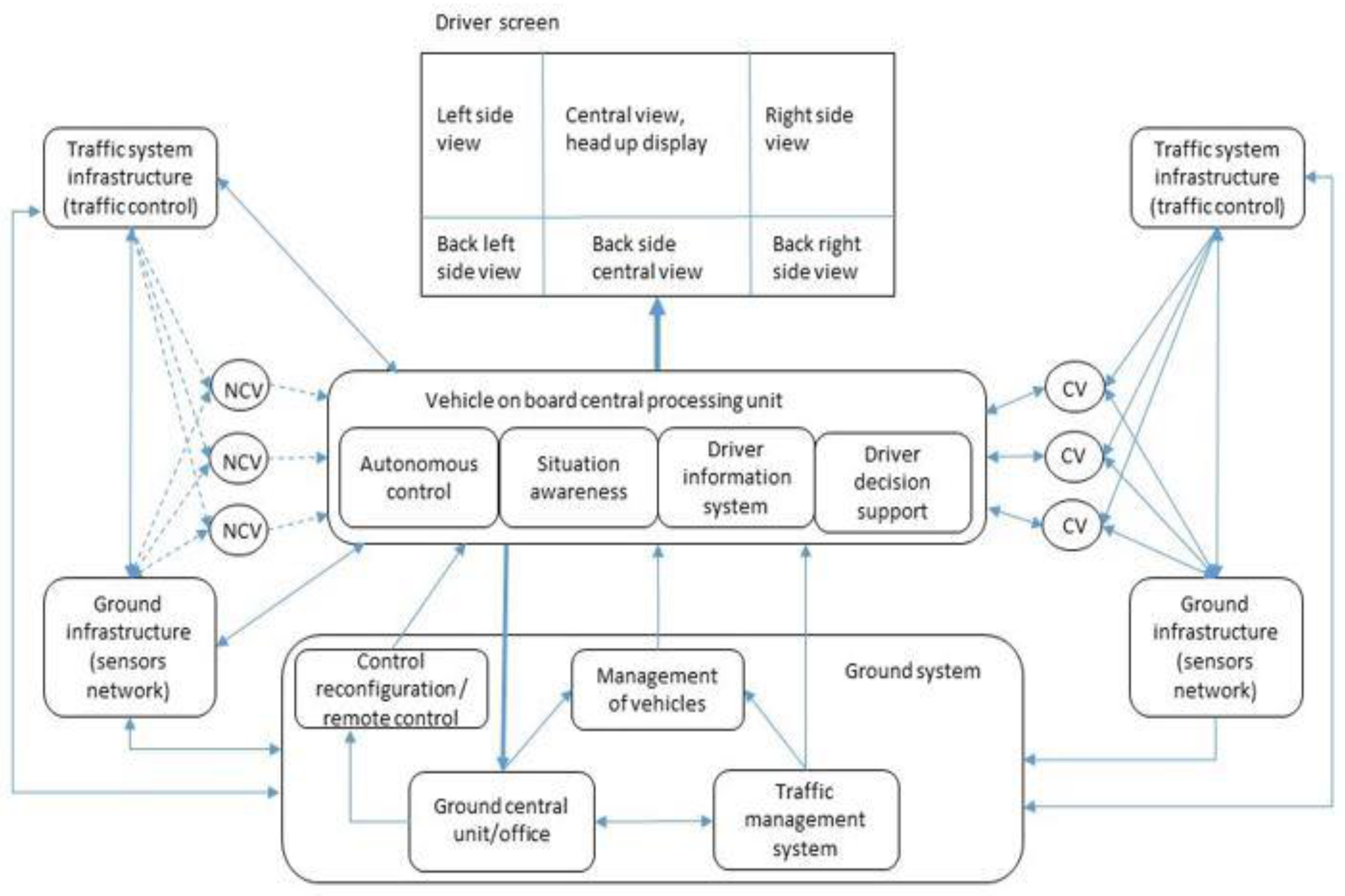
Figure 6.
The simulation results with the differenct velocity.
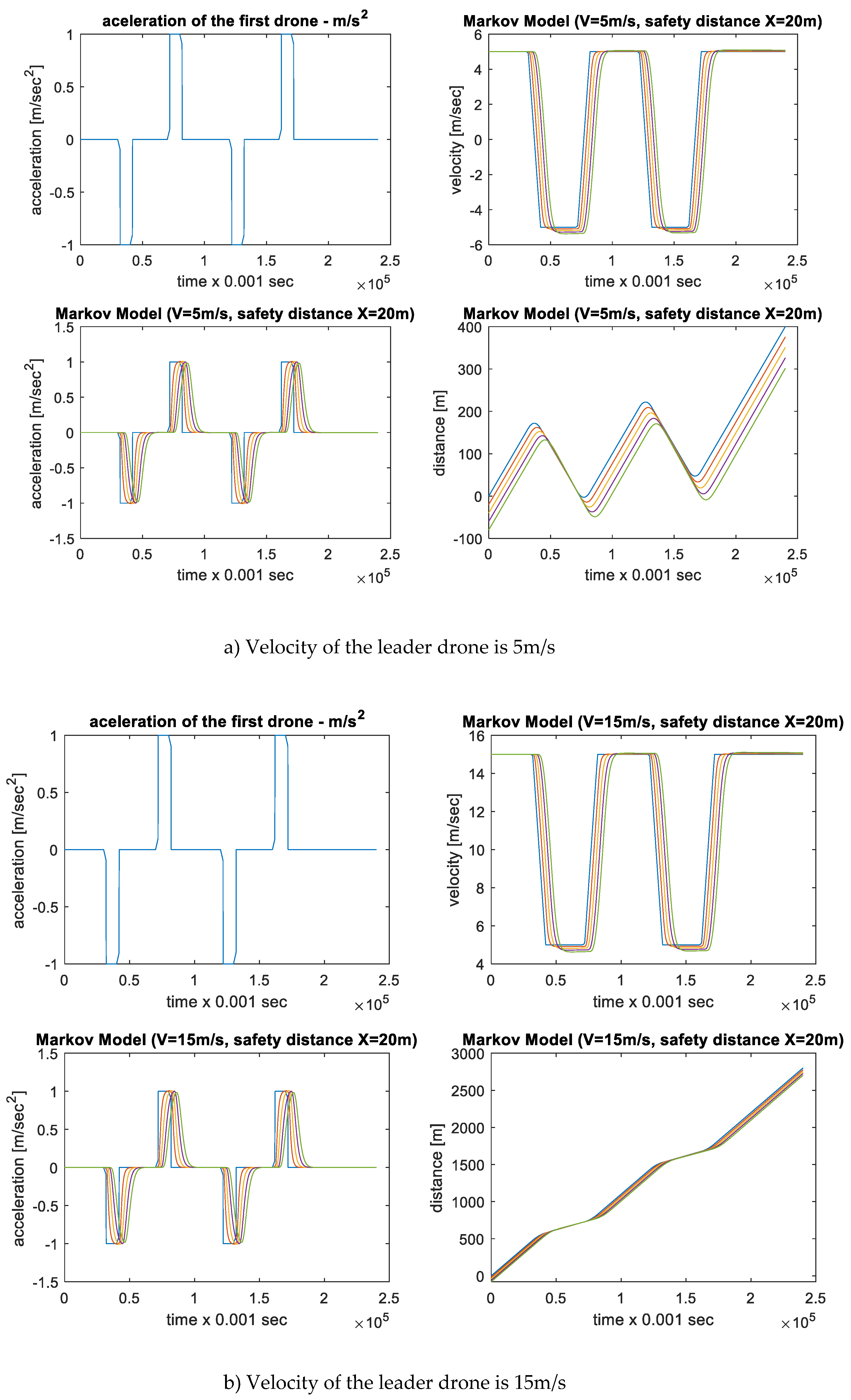
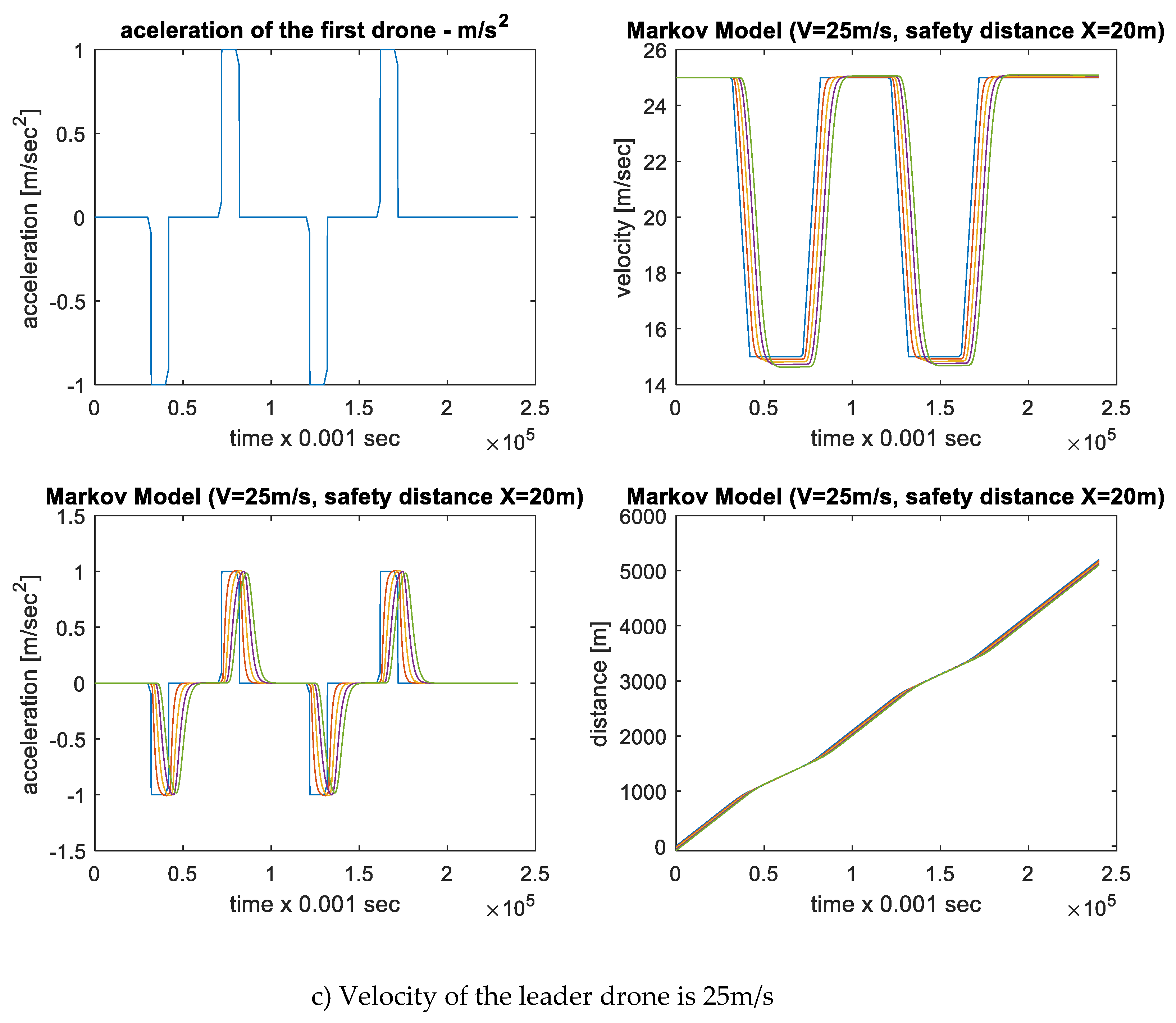
Figure 7.
The process of landing approach of UAV (on the left side), the altitude (middle) and velocity (on the right side) of the landing process in the opposite of the wind direction.
Figure 7.
The process of landing approach of UAV (on the left side), the altitude (middle) and velocity (on the right side) of the landing process in the opposite of the wind direction.
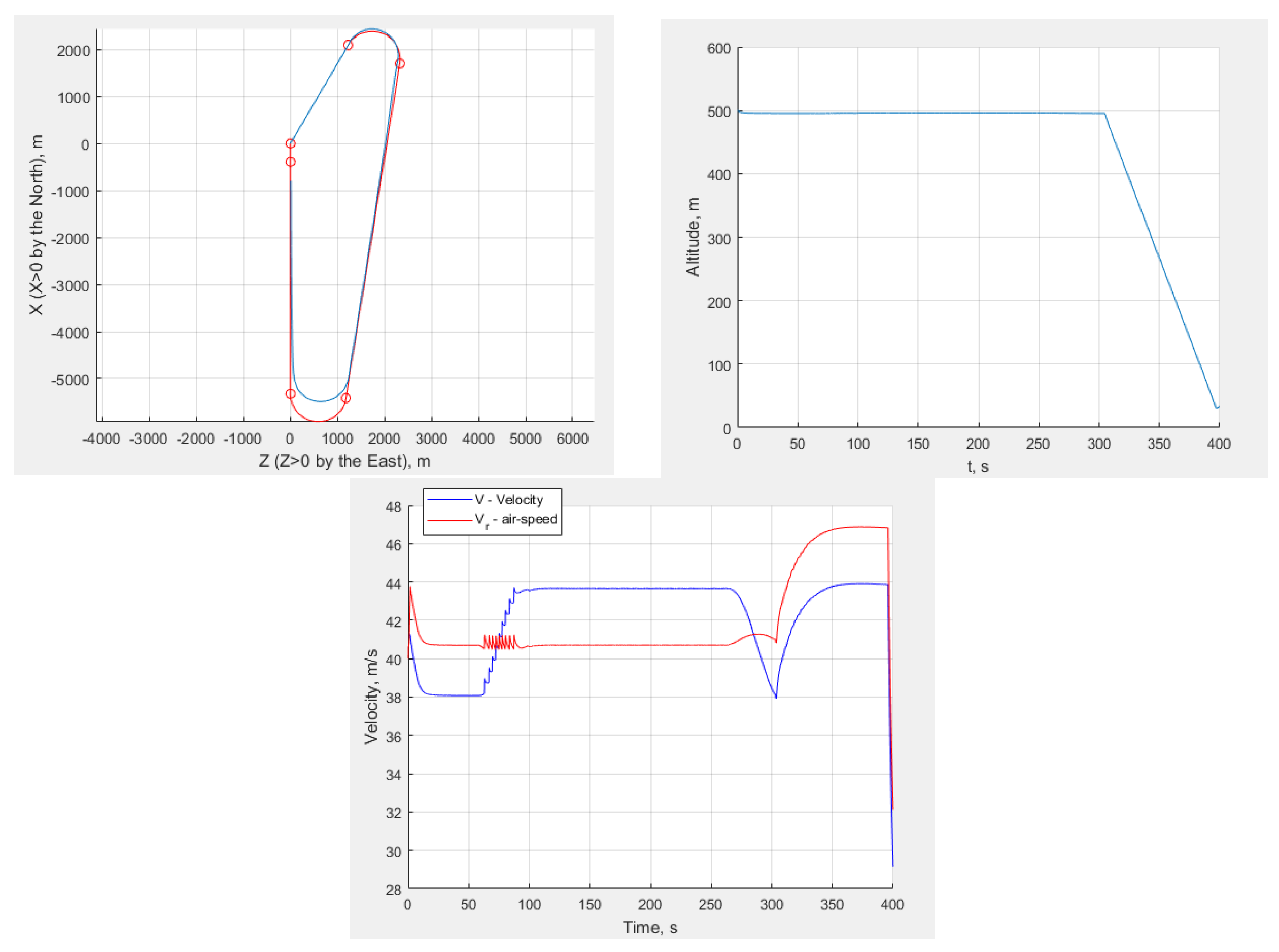
Figure 8.
Investigation of the landing process.
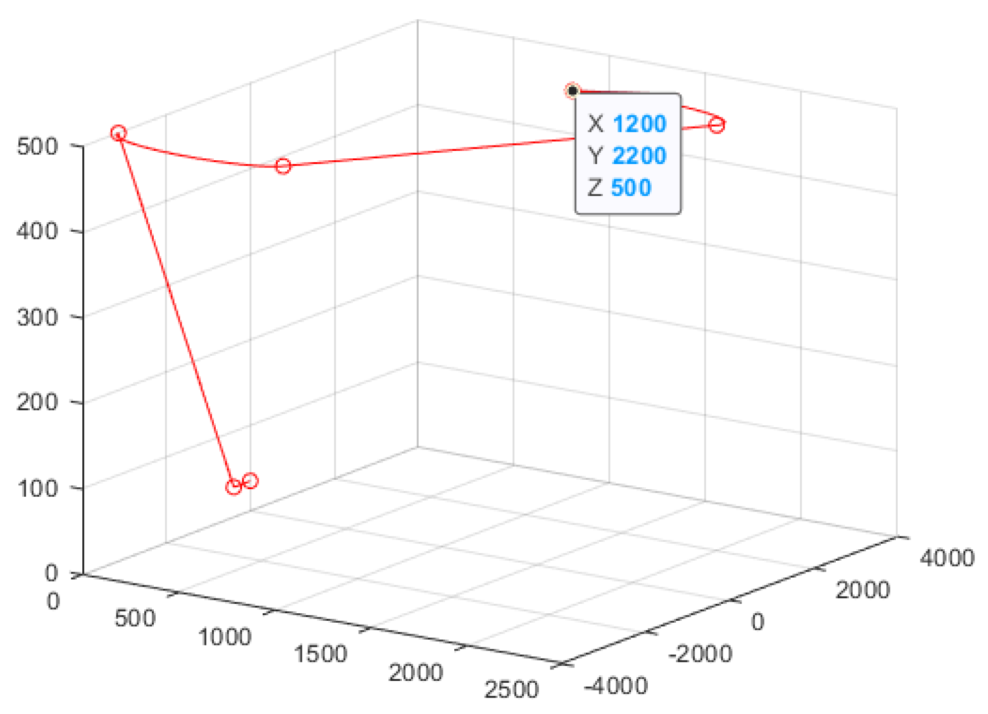
Figure 9.
The process of landing approach of UAV (on the left side), the altitude (middle) and velocity (on the right side) of the landing process in the shortest distance.
Figure 9.
The process of landing approach of UAV (on the left side), the altitude (middle) and velocity (on the right side) of the landing process in the shortest distance.
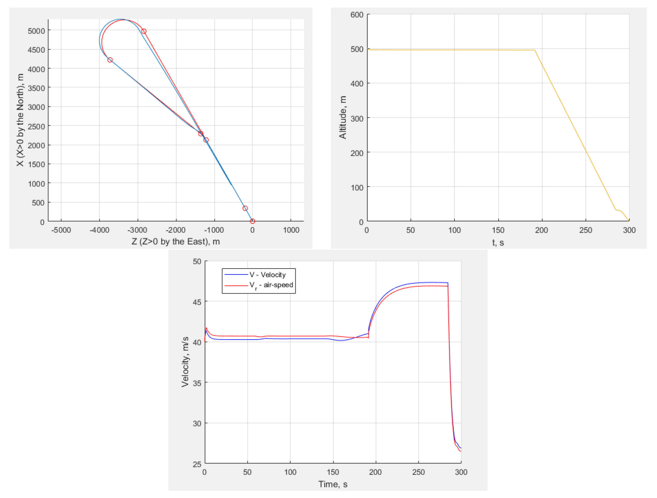
Figure 10.
Investigation of the landing process.
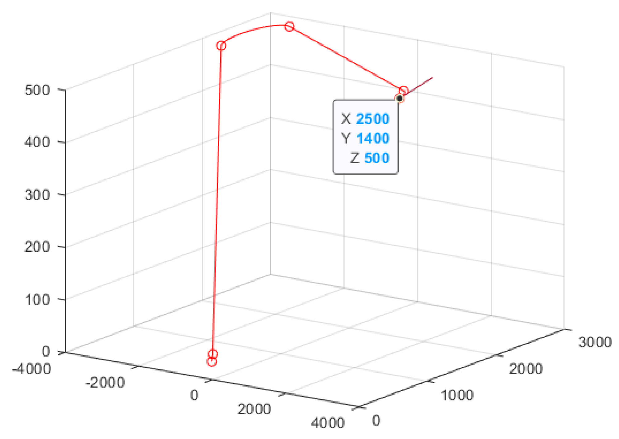

Table 1.
Formulas used for calculating the distance of landing orbit.
| The circle of left turning | The circle of left connecting | Angles |
|---|---|---|
Table 2.
Formulas used for calculating the distance of landing orbit.
| The circle of left turning | The circle of right connecting | Angles |
|---|---|---|
Disclaimer/Publisher’s Note: The statements, opinions and data contained in all publications are solely those of the individual author(s) and contributor(s) and not of MDPI and/or the editor(s). MDPI and/or the editor(s) disclaim responsibility for any injury to people or property resulting from any ideas, methods, instructions or products referred to in the content. |
© 2024 by the authors. Licensee MDPI, Basel, Switzerland. This article is an open access article distributed under the terms and conditions of the Creative Commons Attribution (CC BY) license (https://creativecommons.org/licenses/by/4.0/).
Copyright: This open access article is published under a Creative Commons CC BY 4.0 license, which permit the free download, distribution, and reuse, provided that the author and preprint are cited in any reuse.


