
Submitted:
22 October 2025
Posted:
29 October 2025
You are already at the latest version
Abstract
With the development of the low-altitude economy, a massive number of unmanned aerial vehicles (UAVs) are being deployed in logistics, cruising, communication, and other scenarios, leading to a rapid increase in collision risks. To enhance safety, a structured management method for UAVs in low-altitude airspace is proposed. This method utilizes an intent-driven digital twin system that organizes low-altitude airspace into layers and facilitates the planning of UAV cruising paths. This study simulates the energy consumption and collision risk of logistic, cruising, and communication UAVs in layered airspace under four types of cruising routes, with the collision risk in unstructured airspace simulated as a control group. The approach aims to reduce collision conflicts among UAVs and between UAVs and terrestrial structures, while simultaneously improving UAV performance and energy efficiency. The cruising patterns include various strategies such as random cruising, circular cruising, hovering, vertical boundary cruising, and coordinated cruising with a single UAV. Ultimately, the management of UAV layers and cruising strategies for multiple intent-driven UAVs are integrated and coordinated within the digital twin system, effectively reducing UAV collision risks and energy consumption.
Keywords:
UAV
; low-altitude airspace
; collision conflict risk
; intent driven
; digital twin
1. Introduction
At present, the world is undergoing a transformation in transportation modes, with aerial unmanned traffic serving as a key representative. Drones of various types have become deeply integrated into every aspect of our lives and work. In response, countries are actively advancing the development of next-generation air traffic control systems that integrate both manned and unmanned aircraft. These efforts include policy and system reviews, research on traffic regulations, and the exploration of key technologies related to UAV (Unmanned Aerial Vehicle) airspace.
The United States has released the “Overview of NASA’s Next Generation Air Transportation System (NextGen) Research” report [1]. This report outlines a vision for advanced air traffic centered on unmanned aircraft and proposes a development strategy. It also presents recommendations for the U.S. to maintain its leadership in this field, conducts a comparative analysis of the technical maturity of UAV airspace integration, and outlines development pathways and related projects for advanced air traffic.
The European Union has embraced the concept of the “Digital European Sky” as the core of its SESAR 2020 digital vision [2], incorporating research on advanced air traffic services, particularly those represented by unmanned aircraft.
China has also issued several guiding documents to promote the development of the drone industry [1]. In August 2020, to support the high-quality development of China’s general aviation sector, the Ministry of Transport officially released the “Regulations on the Management of General Aviation Business Licensing,” further clarifying the regulatory framework for related industries. By the end of 2021, China had 370 general aviation airports under registered management, 599 traditional general aviation enterprises that had obtained business licenses, and 3,018 registered general aviation aircraft. The drone industry has also experienced rapid growth. By 2022, China was home to more than 1,200 UAV manufacturers, with over 340,000 registered drones. China’s civilian UAV market accounted for more than 70% of the global total [2].
With the expansion of the general aviation industry chain and the emergence of new business models such as “drone +”, which involves integrating drones with other industries to upgrade operations and improve efficiency, China’s economy is fostering a new development model — the low-altitude economic model. Low-altitude UAVs are being rapidly applied in various sectors, including industrial and agricultural operations, consumer entertainment, logistics and transportation, urban management, and more.
Low-altitude airspace refers to the airspace above the Earth’s surface that can be operated by general aircraft at a true altitude of 1,000 meters or below. It is a crucial component of the national airspace system and an important strategic resource [3]. The capacity of low-altitude airspace indicates the maximum number of aircraft movements that can be safely accommodated within a given time period, also known as the volume of low-altitude air traffic services.
Currently, the composition of low-flying aircraft in China has undergone significant changes. Since 2019, the number of flights involving commercial, government public safety, and emergency drones has exceeded that of manned aircraft by more than double [4].
However, the total amount of low-altitude airspace currently open in China remains relatively limited, with a low altitude ceiling and strict regulatory controls. Due to the complexity of low-altitude airspace networks, low-altitude network management primarily faces three key challenges: the availability and security requirements of route networks are increasing, the scale and complexity of sensing networks are rising sharply, and the service capabilities provided by UAV networks need to be more flexible [3].
The challenges brought by low-altitude airspace network management to managers and operators mainly manifest in the following three aspects: the network maintenance capabilities of managers are limited, the flight environment for UAVs is becoming increasingly complex, and the input costs for operators are constrained. In light of these current challenges, it is essential to develop a network management technology that enhances operational efficiency, is highly autonomous, and possesses comprehensive intelligence.
At present, there are three primary methods for data transmission and communication in drones: radio (digital signal transmission system), Wi-Fi, and operator public networks. As one of the key communication methods for UAV data transmission, the operator network simulates the current operation of the UAV network through digital twin technology during the processes of digitization, informatization, and intelligence. It enables real-time monitoring of UAV-related information such as business operations, flight routes, and locations via a virtualization platform. At the same time, by leveraging intention-driven networks and business application scenarios, the future state of the urban low-altitude airspace network can be predicted, allowing for proactive optimization and adjustment of the low-altitude airspace network. This efficient, on-demand management of fast-moving and large-scale low-altitude networks will help reshape the air traffic system and provide boundless opportunities and development potential for the emerging low-altitude economy driven by drones.
This paper addresses the challenges of UAV route management and wireless resource scheduling in urban low-altitude airspace. It is built upon an intent-driven and digital twin-based low-altitude airspace system that leverages the operator network, with a focus on the core difficulties and key scientific issues currently faced in urban UAV application management. By constructing urban UAV management schemes from the perspectives of intent-based business, UAV operation control, and digital twin low-altitude airspace construction, this work provides a reference for the development of future advanced air traffic models.
The main contributions of this paper are as follows.
- A multi-task UAV low-altitude airspace management system is designed based on an intent-driven digital twin framework.
- The urban low-altitude airspace layer planning process and the algorithm for assigning UAV business intents are proposed.
- Comparison of UAVs collision conflict and comparison of collision conflict between UAVs and buildings in urban, suburbs and rural region with different cruising ways.
2. Background and Related Work
2.1. Low Altitude Drone Dectection
UAV detection functions as the sensory component of the UAV control system, and effective management can only be achieved when targets are promptly and accurately identified. Currently, the primary methods for UAV detection include radar detection, radio spectrum monitoring, visible/infrared detection, acoustic identification, metal detection, and others.
2.2. Radar Detection
Radar can detect the position of low-altitude UAVs by analyzing the reflected waves from flying objects. It can extract information such as the target’s shape, size, angular direction, radial velocity, distance, and micro-Doppler characteristics. The typical detection range of radar for drones is between 1 and 5 kilometers.
The advantages of this technology include its maturity and the ability to detect targets at long distances. However, it also has several limitations: it struggles to detect low-altitude drones when they are hovering; it is prone to false positives and cannot accurately distinguish between kites, birds, and low-altitude UAVs; the transmitted signals may interfere with other communication signals; it is ineffective in detecting drones that are obscured by trees or buildings; and high-precision radar systems tend to be costly [5].
2.3. Radio Spectrum Monitoring
Low-altitude UAVs need to communicate with the external environment to transmit payload data and control flight operations. The radio signals generated during this process are typically specific and identifiable. The UAV communication frequency bands mainly include the 2.4 GHz band (primarily used for drones and toy drones that do not require payload data transmission), the 2.4 + 5.8 GHz combination (used for separating payload data and flight control signals on different frequency bands), and flight control signals transmitted via the 433 MHz, 868 MHz, and 915 MHz bands. Payload data transmission is typically carried out over the 1.3 GHz band.
In complex electromagnetic environments, low-altitude UAVs generally adopt a modulation mode that combines frequency modulation (FM) with spread spectrum techniques for flight control signals. Radio frequency (RF) monitoring identifies low-altitude UAVs by scanning their operating frequencies, with a typical detection range of 1 to 6 kilometers. The advantages of this technology include the absence of radiation, mature implementation, and the ability to detect UAVs at relatively long distances. However, a key limitation is that it is ineffective when the drone is operating in a silent or non-transmitting mode [4].
2.4. Visible/Infrared Detection
This technology detects drones based on their visual characteristics or thermal signals, with a detection range of approximately 2 km [5]. Its advantage lies in the ability to provide visual and all-weather monitoring; however, the drawback is its relatively short detection distance.
2.5. Acoustic Recognition
This technology identifies UAVs by detecting the unique sound emitted by their motors. This method is low-cost and easy to use, but its detection range is limited to about 200 meters. Due to its short range and susceptibility to environmental noise, the effectiveness of this detection method is significantly reduced in noisy conditions. Acoustic detection is therefore primarily used as a supplementary tool to visible light or infrared detection [5].
2.6. Metal Detection
The landing gear and mechanical components of low-altitude drones are often made of aluminum alloy, while the winding and motor shaft are typically constructed from steel. Therefore, in theory, metal detection methods can be employed to identify low, slow, and small drones. Among various metal detection techniques, electromagnetic induction detection equipment is the most widely used. It operates based on the principle that metal objects interfere with alternating electromagnetic fields, and it is commonly applied in low-metal detection, mine detection, security screening, and other related fields [5].
2.7. Related Work
In Ref. [4], Chen Zhijie, Zhu Yongwen, and Liu Yang investigate the digital airspace system for low-altitude management strategies, with a particular focus on the policy framework, UAV control, and the digital construction of low-altitude airspace. The core of constructing a grid model for urban low-altitude airspace lies in the analysis of spatiotemporal attributes, including the characteristics of the air traffic management structure, traffic flow patterns, airspace configuration, and airborne traffic operation datasets. Based on these analyses, the airspace is subdivided into grid units for efficient air traffic management. Additionally, performance analysis of relevant indicators within the grid units and the calculation of evolving air traffic conditions are conducted. Through these processes, the continuous airspace is discretized into a multi-level grid unit system, thereby establishing a unified four-dimensional spatiotemporal framework for air traffic management.
In Ref. [5], Zhang Hong-hai, Yi Jia, LI Shan, Liu Hao and Zhong Gang review the current research status and development in low-altitude airspace capacity assessment. It proposes an evaluation framework tailored to the needs of low-altitude airspace management in China, summarizes four key elements and related methods, and highlights that the current low-altitude airspace management system is still underdeveloped. It emphasizes the need to conduct capacity assessment method research adapted to China’s airspace management, strengthen the analysis of influencing mechanisms, develop simulation systems, and promote method validation. In addition, the paper underscores the importance of low-altitude airspace capacity assessment in achieving rational resource allocation and ensuring safe and efficient operations. Meanwhile, the knowledge base also mentions that CodeFree, the intelligent assistant for the R& D Cloud, is developed by China Telecom’s R& D Cloud team based on software engineering and large-scale model technologies. It provides one-stop intelligent services to support the intelligent management of the R& D process.
In Ref. [6] , Li Lingling, Han Ruiling, and Zhang Xiaoyan investigate geofence technology, conflict detection, and resolution models. The application of geofence technology is shown to be effective in assessing the capacity of urban low-altitude airspace. The results indicate that the total available airspace at low altitudes is influenced by both the low-altitude obstacle separation standard and the flight altitude, and it increases as the flight altitude rises. In the case of Beijing, the available space in the urban low-altitude airspace is distributed along the main urban traffic routes, exhibiting a concentric pattern that extends outward from the city center to the periphery.
In Ref. [7], QI RuoYu, FAN Jingwen investigate low, slow, and small (LSS) drones. Due to their low speed, low altitude, and small radar cross-section, LSS drones, although widely used in various fields, also pose threats to public and national security. To address these drones, detection technologies such as radar, radio frequency monitoring, visual/infrared detection, acoustic detection, and metal detection can be employed, along with countermeasure technologies including radio frequency jamming, navigation signal spoofing, data link spoofing, and physical interception. Building a fully automated drone countermeasure system is a key direction for enhancing defense capabilities, aiming to achieve automated detection, alerting, and counteraction.
In Ref. [8] , Xie Hua, Su Fangzheng, Yi Jianan, Han Site, and Zhang Xinyu investigate a fine-grained management model for low-altitude UAV flight conflicts. The paper addresses the complexities of low-altitude airspace systems and proposes a UAV flight conflict network model as well as a feature measurement method. Additionally, a fine-grained detection algorithm based on digital grids and an optimal resolution strategy that incorporates priority considerations are introduced. Experimental results demonstrate that the proposed method can dynamically identify UAV flight conflicts in low-altitude environments and significantly improve conflict detection efficiency. It is particularly well-suited for scenarios involving the mixed operation of multiple UAV types, achieving a linear enhancement in detection performance.
In Ref. [9] , Wang Qiqi, Mo Haoyin, and Hu Jiangmin investigate real-time interactive mapping in the context of Digital Twin. A communication network optimization method based on Digital Twin enables the transformation of the network entity space into the corresponding digital twin space within the ecosystem established by the communication network optimization system. Subsequently, network optimization is achieved through the application of intent-based networking, thereby enabling efficient and adaptive improvements in network performance.
In Ref. [10] , Zhou Yaoquan and Liu Zehua propose a UAV-based urban governance scheme along with an evaluation index system. The system collects urban data through UAV-mounted cameras and existing city surveillance cameras, which are then processed by an AI middleware platform. It identifies shortcomings in urban governance, issues early warnings to relevant departments, and effectively evaluates the quality and effectiveness of urban governance.
In Ref. [11], Sun Tao and Zhou Cheng were the first to systematically introduce the concept of a “Digital Twin Network (DTN)”, presenting its system architecture and providing an in-depth analysis of its core technologies. By examining the challenges in DTN development, they outline the potential trajectory for its future evolution.
In Ref. [12], Lin Fengcheng and Qiu Chenhui apply the concept of intent networking to the field of communications and propose an intent-driven hierarchical service experience assurance mechanism. This approach shifts the operational paradigm from “how to do” to “what to do,” enabling ultra-fast service experience assurance driven by natural language, without requiring any manual process intervention. It ensures that the user’s service experience in specific scenarios meets the intent-defined quality level, thereby achieving truly “empathetic” network assurance.
In Ref. [13], Zhou Yangcheng and Yan Shi investigate intent-driven 6G radio access networks (ID-RAN). First, they outline the architecture of ID-RAN, followed by an introduction to key technologies such as intent translation, conflict resolution, configuration activation, network performance evaluation, and optimization. Finally, they present an open software-defined hardware platform to demonstrate the intent-driven networking capabilities of 6G wireless systems.
In Ref. [14], Wang Jianwei, You Jiang, Wan Min, and Gu Jingliang investigate how deep learning-based object detection and tracking technologies offer significant advantages in terms of accuracy and real-time performance. Among current methods, YOLOv5 and CSRT are considered among the most effective in their respective domains, with YOLOv5 excelling in detection speed and CSRT in tracking precision. Building upon these techniques, the paper proposes a dual-resolution capture network and integrates GPU acceleration and TensorRT deployment, thereby achieving stable and real-time tracking of low-altitude UAVs in complex environments.
In Ref. [15] , Deng Junwen proposes a deep learning-based computer vision approach that combines the YOLOv8 object detection algorithm with the SORT multi-object tracking algorithm, enabling real-time detection and stable tracking of small, slow-moving drones in low-altitude environments. Experimental results demonstrate that the algorithm exhibits high real-time performance and stability on the NVIDIA Jetson Orin hardware platform. It is capable of effectively addressing challenges such as the diversity of drone types and complex background conditions, and shows significant potential for application in the defense against small, low-altitude, and slow-moving drones.
In Ref. [16], Zhang Zhuo and Sun Baofen discuss the current development and application of drone detection and countermeasure technologies. They analyze various detection technologies, including radar detection, radio frequency spectrum detection, electro-optical detection, and acoustic detection, as well as countermeasure technologies such as radio frequency interference, net capture, hard-kill technology, laser strike, high-energy microwave strike, lure capture, and control link cracking. The article emphasizes that it is essential to integrate multiple technical approaches and equipment, and to adopt composite solutions in order to achieve effective monitoring and countermeasures against drones. Looking ahead, with the advancement of communication technologies, drone detection and countermeasures will become increasingly challenging. Therefore, full-band detection and interference technologies, along with the flexible deployment of countermeasure equipment tailored to different scenarios, will be required.
In Ref. [17], Zhao Weidong and Wang Tingji introduce mainstream methods for drone detection, including radio, radar, acoustic, and optoelectronic detection systems, and analyze their respective advantages and disadvantages. The paper focuses on explaining the working principles and technical characteristics of a new external radiation source radar detection system, which utilizes echo signals from non-cooperative illuminators for target detection. This system offers several advantages, such as efficient spectrum utilization, enhanced safety, ease of networking, and strong stealth capabilities. By integrating optoelectronic and radio detection equipment, a fully passive, comprehensive, and collaborative low-altitude target detection system can be constructed. The article highlights the limitations of traditional single-detection methods and suggests that the future should focus on integrating multiple detection techniques to improve drone detection capabilities.
In Ref. [18], Kashif Mehmood, H. V. Kalpanie Mendis, Katina Kralevska, and Poul E. Heegaard propose an intent-based network management and orchestration framework for smart distribution grids. By leveraging 5G network slicing and Intent-Based Networking (IBN) technology, the framework supports automation, differentiated service provisioning, and dynamic configuration and optimization of network resources in the distribution grid. The paper discusses application scenarios such as grid monitoring and control, protection, distributed energy management, and demand response, and analyzes the requirements of these scenarios on different 5G use cases, including URLLC, mMTC, and eMBB. The framework realizes efficient and flexible network management by translating user intents into service configuration models and integrating network slicing with network function virtualization.
In Ref. [19] , Yoonseon Han, Jian Li, Doan Hoang, Jae-Hyoung Yoo, and James Won-Ki Hong propose an intent-based software-defined network (SDN) virtualization management platform designed to express high-level tenant requirements and enable the automatic configuration and management of virtual networks. The platform is built on the ONOS SDN controller and the OpenVirteX network virtualization layer, adopting a hierarchical architecture that includes a protocol adaptation layer, an abstraction layer, a virtualization layer, a virtual abstraction layer, and an intent layer. It supports multi-tenancy and the independent operation of virtual networks. Through the definition, composition, conflict detection, and lifecycle management of intents, the platform simplifies network management processes and enhances the flexibility and scalability of network services.
In Ref. [20], Jinyong (Tim) Kim, Eunsoo Kim, Jinhyuk Yang, Jaehoon (Paul) Jeong, Hyoungshick Kim, Sangwon Hyun, Hyunsik Yang, Jaewook Oh, Younghan Kim, Susan Hares, and Linda Dunbar propose an intent-based cloud security service (IBCS) architecture that integrates automation and virtualization, combining the IETF’s I2NSF framework with the ETSI’s NFV architecture. In this architecture, security service consumers can define security policies through high-level intents, which are automatically translated by the system into low-level policies executable by network security functions (NSFs) and dynamically deployed as virtualized security services. Experimental and performance evaluations demonstrate that IBCS significantly reduces deployment and configuration time compared to traditional frameworks, while improving resource utilization efficiency.
In Ref. [21], Aris Leivadeas, Matthias Falkner propose an intent-based virtual network function (VNF) deployment solution that integrates intent-based networking (IBN) and network function virtualization (NFV) technologies. By defining user intent templates and translating them into service chains (SCs), a hybrid VNF placement algorithm is employed to meet varying QoS and security requirements. Experimental results demonstrate that the proposed method performs well in reducing latency, optimizing resource utilization, and improving multi-tenancy efficiency. Additionally, the solution supports intent refinement through user feedback to further enhance configuration accuracy.
In Ref. [22], Mehdi Bezahaf, Marco Perez Hernandez, Lawrence Bardwell, Eleanor Davies, Matthew Broadbent, Daniel King and David Hutchison present an intent-based system implemented on the Mininet test platform using the ONOS OpenFlow controller and OVS switches. The system integrates an online change detection algorithm to identify network anomalies and automatically generate intents. The system architecture consists of an intent plane, a management plane, and a control plane. Experimental results validate the feasibility of the system in detecting link saturation and adjusting traffic paths accordingly.
In Ref. [23], Muhammad Faraz Hyder and Tasbiha Fatima propose an intent-based moving target defense (IBN-based MTD) framework to counter Crossfire DDoS attacks. The framework utilizes the Rest API of the ONOS SDN controller and DNS port redirection techniques to divert traffic from the primary host to virtual shadow hosts, thereby concealing the real target and rendering the attack ineffective. Simulation tests conducted using Mininet and the ONOS controller demonstrate that traffic redirection is successfully executed with low computational overhead, effectively mitigating the attack.
In Ref. [24], Aris Leivadeas and Matthias Falkner present an intent-based virtual network function (VNF) deployment solution that integrates intent-based networking (IBN) and network function virtualization (NFV) technologies to enable automated VNF deployment in multi-tenant cloud infrastructures. The solution expresses user intents in a templated format, which are then translated into service chain configurations. It also addresses conflicting intents and aggregates similar ones. A hybrid VNF deployment algorithm is introduced, including optimal, best-effort, and greedy approaches, to meet diverse QoS and security requirements. Experimental results demonstrate that the proposed method offers significant advantages in resource utilization, latency optimization, and intent adjustment.
3. Digital Twin System
Digital twin networks operated by telecom operators—such as Orange (formerly France Telecom), China Telecom, and AT&T (American Telephone & Telegraph)—are digitally constructed to mirror physical network entities, enabling real-time interaction between the physical and virtual domains [9]. By facilitating high-fidelity, real-time communication between these two realms, the digital twin network system supports efficient analysis, diagnosis, simulation, and control of the physical network.
With the support of operators’ large-scale information infrastructure, a large-scale low-altitude airspace digital twin system can be established. This system enables the digital reconstruction and representation of extensive airspace within the information space, and supports mapping management and usage control of the airspace. Ultimately, it aims to achieve the following objectives:
- Visual analysis of the airspace. Based on the visualized state of airspace usage, an airspace system diagram is established to accurately capture the actual distribution and flight status of low-altitude drones across the entire airspace. This provides support for dynamic airspace and drone management based on a shared understanding.
- Measurable processing of the airspace. By developing spatiotemporal big data technologies for airspace management, a novel numerical calculation method is established to assess airspace performance and status. This enables the measurement of overall airspace traffic performance and lays the foundation for low-altitude drone traffic flow control and combat airspace utilization.
- Computable decision-making for the airspace. A set of computational decision-making models is developed based on the digital twin airspace, forming the basis for collaborative management of airspace traffic flow control. At the same time, these models provide support for airspace optimization and operational control of low-altitude drones through algorithmic processing.
As a key technical support system for the low-altitude airspace, the digital twin network comprises four core components: models, interaction, data, and mapping, as illustrated in Figure 1.
- Data is the foundational element in the development of digital twin networks. A centralized data-sharing repository is established to serve as the authoritative source for the digital twin of the wireless intent-driven network. This repository effectively stores both historical and real-time data, including configuration, topology, status, logs, and user service information related to the low-altitude airspace physical network. It provides essential data support for the network twin.
- Models are the core source of capabilities in digital twin networks. Rich and functional data models can be flexibly combined to generate various model instances, supporting a wide range of network applications.
- Mapping refers to the high-fidelity visual representation of physical entities in the low-altitude airspace network through the network twin. This is one of the most distinctive features that differentiates digital twin networks from traditional network simulation systems.
- Interaction between the virtual and physical domains is a critical component. The network twin bridges the gap between digital representations and actual network components through unified interfaces, enabling real-time data acquisition and management of the physical network, as well as rapid diagnostic assessments and analyses.
Based on the definition and the four core elements of a digital twin network, its architecture can be designed as a “three-layer, three-domain, dual-loop” structure, as illustrated in Figure 2:
- The three layers include the physical network layer, the twin network layer, and the network application layer, which together form the digital twin network system.
- The three domains within the twin network layer are the data domain, the model domain, and the management domain, corresponding to three subsystems: the data sharing warehouse, the service mapping model, and the network twin body management.
- The “dual-loop” mechanism consists of the inner-loop, which performs simulation and optimization within the twin network layer based on the service mapping model, and the outer-loop, which enables control, feedback, and optimization of network applications based on the three-layer architecture.
- Physical Network Layer. Various network elements within the physical network interact with the network twin through the twin southbound interface to exchange network data and control information. As the physical counterpart of the network twin, the physical network can represent a cellular access network, a cellular core network, a data center network, a campus or enterprise network, an industrial Internet of Things (IoT), and so on. It may be a subnet within a single network domain (e.g., wireless or wired access network, transport network, core network, bearer network, etc.), or it may span multiple domains as an end-to-end cross-domain network. The physical network can either encompass all infrastructure within a network domain or focus on specific components, such as wireless spectrum resources or user-plane network elements in the core network.
-
Twin Network Layer. The twin network layer is a defining characteristic of the digital twin network system, consisting of three key subsystems: the data sharing storage, the service mapping model, and the network twin management.
- The data sharing storage subsystem is responsible for collecting and storing various types of network data, and for providing data services and a unified interface to the service mapping model subsystem.
- The service mapping model subsystem performs data-driven modeling and delivers data model instances to diverse network applications, thereby enhancing the agility and programmability of network services.
- The network twin management subsystem oversees the full life-cycle management and high-fidelity visual representation of the network twin.
The data sharing storage collects and stores various configuration and operational data of network entities through the southbound interface, establishing a single source of truth for the digital twin network. It provides accurate and comprehensive data to support different network models and their applications, including but not limited to network configuration information, operational status, and user service data. The data sharing storage primarily performs the following four functions:- Data Collection. It extracts, transforms, and loads network data, along with cleaning and prep-processing, to enable efficient distributed storage of large-scale data.
- Data Storage. By integrating the diverse characteristics of network data and leveraging multiple storage technologies, it ensures the efficient and scalable storage of massive volumes of data.
- Data Services. It provides a range of data services to the service mapping model subsystem, including fast query, concurrency control, batch processing, and unified interfaces.
- Data Management. It manages data assets, security, quality, and metadata to ensure data integrity and usability.
As a cornerstone of the digital twin network, the completeness and accuracy of the data in the data sharing storage directly influence the richness and precision of the resulting data models.The service mapping model consists of two components: the foundational model and the functional model. The foundational model is a network element and topology model constructed based on the basic configuration, environmental information, operational status, and link topology of network entities. It enables a real-time and accurate representation of the physical network.The functional model is designed for specific application scenarios and leverages network data from the data warehouse to construct various data models for network analysis, simulation, diagnosis, prediction, and assurance. These functional models can be developed and extended across multiple dimensions:- By network type, models can be built for single network domains (e.g., mobile access network, transmission network, core network, bearer network) or for multi-domain networks.
- By function type, models can be categorized into types such as status monitoring, traffic analysis, security drills, fault diagnosis, and quality assurance.
- By scope of application, models can be classified as either general-purpose or specialized.
- By network lifecycle management, models can be divided into planning, construction, maintenance, optimization, and operation models.
By integrating these dimensions, more specific and scenario-oriented data models can be created. For example, a traffic load balancing and optimization model for a core switch in a campus network can be developed, and model instances can be used to support the corresponding network applications.The foundational and functional models deliver services to upper-layer network applications through individual instances or combinations of instances, thereby maximizing the agility and programmability of network services. At the same time, model instances must be programmatically driven to perform comprehensive simulation and validation within virtual twin network elements or network topologies, supporting objectives such as prediction, scheduling, configuration, and optimization. This ensures the effectiveness and reliability of any changes when they are deployed to the physical network under change control.Network Twin Management realizes the management functions of the digital twin network, offering full lifecycle recording, visual presentation, and control over various elements of the network twin, including topology management, model management, and security management.- Topology Management generates a virtual topology that mirrors the physical network based on the foundational model, and provides multi-dimensional and multi-level visual representations of the network structure.
- Model Management supports the creation, storage, updating, and management of model combinations and application associations for various data model instances. It also enables the visual presentation of the data loading process, simulation validation, and the outcomes of model execution.
- Security Management, in conjunction with data management in the shared data warehouse, is responsible for safeguarding the data and models within the digital twin network. It encompasses mechanisms such as authentication, authorization, encryption, and integrity protection.
- Network Application Layer. Network applications input requirements to the twin network layer through the twin northbound interface and deploy services within the twin network layer using modeled instances. After thorough validation, the twin network layer sends control updates to the physical network via the southbound interface. This architecture enables the rapid deployment of network innovation technologies and various applications—such as network operations and optimization, network visualization, intent verification, and network autonomous driving—with lower costs, higher efficiency, and minimal disruption to existing network services.
Based on the above architecture, the network twin leverages optimization algorithms, management methodologies, and domain expertise to evaluate, resolve issues, replicate scenarios, and oversee the physical network of low-altitude airspace throughout its entire life-cycle. It ensures seamless and real-time synchronization between the physical network and its digital counterpart, thereby enhancing the capability to monitor and manage drone conflicts. This approach enables a more cost-effective, efficient, and minimally disruptive management of the low-altitude network, supporting intelligent and streamlined oversight.
In terms of preventing drone network conflicts at both the network and airspace levels, leveraging insights derived from the digital twin network’s data enables a clear understanding of drone service intentions and facilitates timely adjustments to network and route configurations. This timely response effectively accommodates the dynamic demands of low-altitude services while safeguarding against accidents and operational disruptions. An intent-driven network can continuously learn and adapt to the evolving demands and the changing state of the low-altitude airspace network, including through the integration of various security features that continuously protect the operation of low-altitude routes and networks. The specific capability requirements for wireless intent-driven networks include the following:
- Information Perception and Big Data Analysis and Processing: The intent-driven network necessitates the acquisition of operational and maintenance records, wireless transmission data, and measurement information from low-altitude drones within the airspace network. This is achieved through information-gathering techniques and advanced data probes. These records can serve as key indicators for identifying emerging service requirements. Moreover, wireless transmission data and terminal measurement data enable the evaluation of the current performance of network configuration policies and drone flight paths, allowing for a comparison between the actual outcomes of network execution and route planning and the expected results based on service intents.
-
Conversion and Maintenance of Business Intents: In the context of low-altitude airspace, business intents can be categorized into various forms of services that the communication network provides to end users. Moreover, by analyzing the video stream of drone image transmission signals, it is possible to infer the operational intent of drones and collect relevant image data. [6] For example, logistics drones, cruising drones, relay DBSs (Drone Base Stations), and public safety drones each serve distinct purposes. When facing different urban scenarios, the same type of business intent may vary in its specific requirements.For instance, DBSs deployed in widely covered areas with dispersed and highly mobile users require different configurations compared to those used for remote sensing detection, which often involves high-capacity scenarios demanding high data transmission rates—such as 3D stereo video and augmented reality. Similarly, smart city logistics involves diverse load scenarios with a large number of sensor devices.Abstracting business intents into actionable requirements necessitates specific network and route planning configurations. Given the large number of urban low-altitude drones and the complexity of the low-altitude traffic network, it is impractical to perform this manually. Therefore, drone business intents must be automatically translated into network resource and airspace route configuration policies.
- Automatic Execution and Intelligent Optimization of Route Planning and Network Configuration: After determining the network and route configuration policies, these policies must be issued to the base stations connected to the drones and executed promptly. With a large number of low-altitude drones in operation, the complexity of route configuration increases exponentially. By leveraging big data and artificial intelligence technologies, the wireless intent-driven network can autonomously adapt to various drone networking modes, route configuration strategies, and wireless resource allocation strategies. It integrates with the automatic configuration distribution capabilities of software-defined networking (SDN) and network function virtualization (NFV), which are capable of supporting a massive number of connections, ultra-low latency, and ultra-high bandwidth required for drone communications. This integration enables automation in the processes of strategy development, deployment setup, self-tuning, and anomaly detection throughout the network lifecycle, transforming the network into a self-regulating and autonomous system.
To ensure the normal operation of drones within the low-altitude network, both physical and network faults must be effectively predicted and automatically detected, with the network and flight routes being continuously optimized. Based on the information perception and big data analysis capabilities of the digital twin airspace network, artificial intelligence can extract hidden features from network and mechanical data, mapping them to key performance indicators. This allows for real-time monitoring of changes in drone flight status, mechanical condition, and network performance, enabling early fault prediction and identification. The system can then proactively optimize the network and routing strategies, improve the efficiency of fault resolution and maintenance, and support the stable and sustainable development of the urban low-altitude airspace economy.
4. Intent-Driven Airspace System Based on Digital Twin Network
4.1. Structure of Low-Altitude Airspace
The classification of urban low-altitude airspace presents a significant challenge that differs from traditional low-altitude airspace classification scenarios. In urban environments, obstacles and protected zones near buildings introduce complexities that necessitate the development of a novel classification framework for drone traffic. The digitization of urban low-altitude airspace is becoming a critical trend for future advancements. Low-altitude resources, similar to road resources, fall within the same domain of traffic infrastructure. This paper argues that, in the future, urban roads, buildings, streetscapes, and available low-altitude airspace should be represented and digitally modeled in an integrated and unified manner.
The configuration of urban low-altitude airspace is a key factor in determining its overall capacity. Such configurations impose constraints on the flight altitude, trajectory, and speed of drones operating within the designated airspace. As a result, operational efficiency varies across different airspace configurations, which in turn affects the capacity of the low-altitude airspace in urban areas. The structure of urban low-altitude airspace can be classified into four primary types [6].
-
Unstructured (Mixed Flight Structure) Airspace:This type of airspace allows drones to operate with minimal constraints, primarily limited by physical factors such as weather conditions, stationary obstacles, and terrain. Drones fly at their optimal altitude and speed, following a direct “origin → destination” path. However, the flight mode within this structure is inherently complex, and the level of safety is relatively low [6].
-
Layered Structure Airspace:The layered structure divides the urban low-altitude airspace into horizontally stacked, belt-like layers by imposing altitude restrictions on drone flights. Drones select the appropriate altitude layer based on their flight requirements, with longer flight distances typically corresponding to higher altitude layers. This structure simplifies the flight mode and provides a moderate level of safety [6].
-
Block Structure Airspace:Building upon the layered structure, the block structure incorporates the influence of the urban layout. With the city center as the focal point, each altitude layer is further subdivided into radial zones, forming a block-based airspace structure with defined altitude and directional constraints. This approach optimizes drone flight paths by leveraging both directional and altitude advantages, enhancing operational efficiency [6].
-
Tube Structure Airspace:The tube structure establishes a four-dimensional flight pipeline that includes origin, destination, altitude, and time. It enforces strict constraints on drone flight altitude, direction, and speed, and provides fixed, pre-planned, and conflict-free routes for low-altitude urban airspace. Each route is composed of nodes (one or more connection points) and edges (flight paths connecting two nodes). Routes at the same altitude do not intersect except at designated nodes. While the tube structure ensures the highest level of safety, its stringent constraints may reduce flight efficiency [6].
Figure 3.
the structure of urban low-altitude airspace
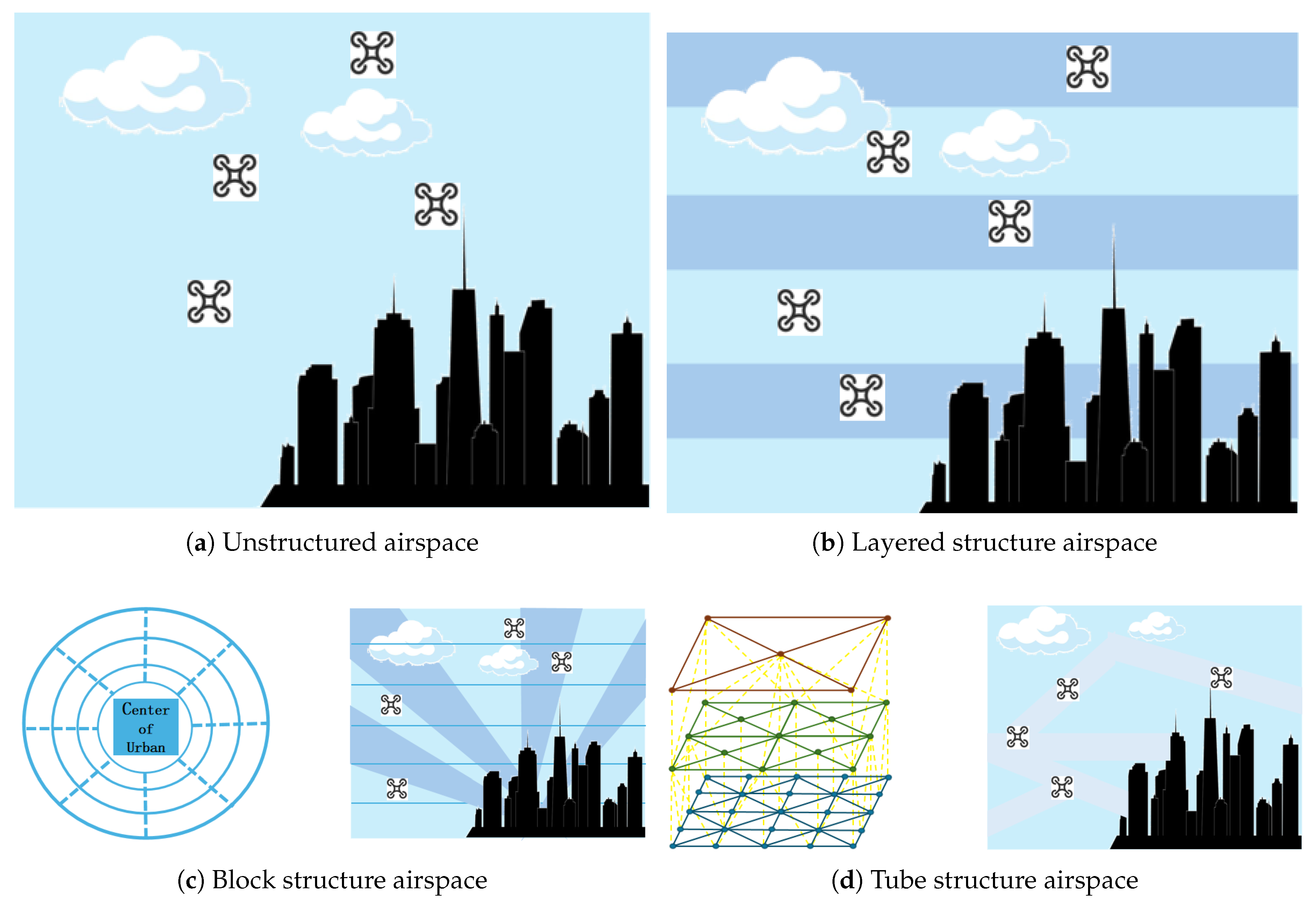
The four aforementioned types of urban low-altitude airspace structures are designed to reduce the complexity of traffic flows within the airspace, thereby improving flight safety. However, an excessive number of restrictions may result in a reduction of the airspace’s overall capacity. Further analysis shows that the layered structure enables drone navigation within designated lanes without significantly compromising operational efficiency [6]. This structure achieves the highest levels of both safety and capacity in urban low-altitude airspace, making it the most suitable airspace structure for urban environments. In contrast, the unstructured type exhibits the lowest safety due to its complex flight patterns, while the block and tube structures suffer from reduced capacity as a consequence of their strict constraints.
Consequently, the urban low-altitude network should adopt a layered structure and be integrated with satellite communication and navigation systems to establish a unified space-air-ground network. Such an integrated framework is crucial for enabling the coordinated operation of ground vehicles and drones. From the perspective of land-air collaboration, the simultaneous operation of ground vehicles, near-surface airspace, various low-altitude drones, and manned general aviation aircraft forms a cross-domain, heterogeneous traffic scenario. This scenario imposes distinct requirements in terms of scale, speed, and operational control response time.
The management of urban low-altitude airspace, which involves billions of grid-based airspace entities, necessitates the development of a novel data model to accurately characterize low-altitude airspace activities. This model should integrate spatiotemporal frameworks and performance metrics, and provide a structured representation of buildings, obstacles, available communication, navigation, and detection resources, as well as information on low-altitude flight status and drone-related business activities. Consequently, there is an urgent need to develop an innovative geographic information system specifically tailored for grid airspace entities. This system should establish a grid coordinate framework to effectively describe drone airspace operations. Moreover, it is essential to design mathematical models for data analysis and management that align with operational scenarios, thereby enabling quantitative evaluation and optimization of airspace usage.
The management of grid airspace entities should be integrated with a low-altitude intelligent network, allowing the realization of “safe flight” in urban low-altitude airspace through the support of advanced drone traffic management technologies that prevent collisions.
This paper proposes a framework for airspace management and the development of supporting systems for drones categorized by distinct business intents, such as logistics drones, cruising drones, and drone base stations (DBSs). From the perspective of airspace entry requirements for unmanned aerial vehicles (UAVs), it is crucial to adopt a comprehensive approach that supports the construction and demonstration of an air traffic management system based on hierarchical airspace governance. Additionally, the concept of hierarchical airspace governance can be guided by a digital grid airspace model, enabling dynamic and efficient management of the entire low-altitude airspace across all grid levels.
4.2. Implementation and Guarantee of UAV Business Intent Based on Digital Twin Network
This study investigates the business intent of drones as derived from users’ natural language inputs. The process involves multiple stages, including intent recognition, intent translation, strategy formulation and deployment, and intent verification, all of which are aimed at enabling the efficient execution of drone-related business operations. The analysis in this paper classifies business intents into three distinct categories: logistics drones, cruising drones, and drone base stations (DBSs).
The dual closed-loop process, which is driven by the drone’s intent, is illustrated in the figure below.
Figure 4.
intent-driven dual closed-loop process.
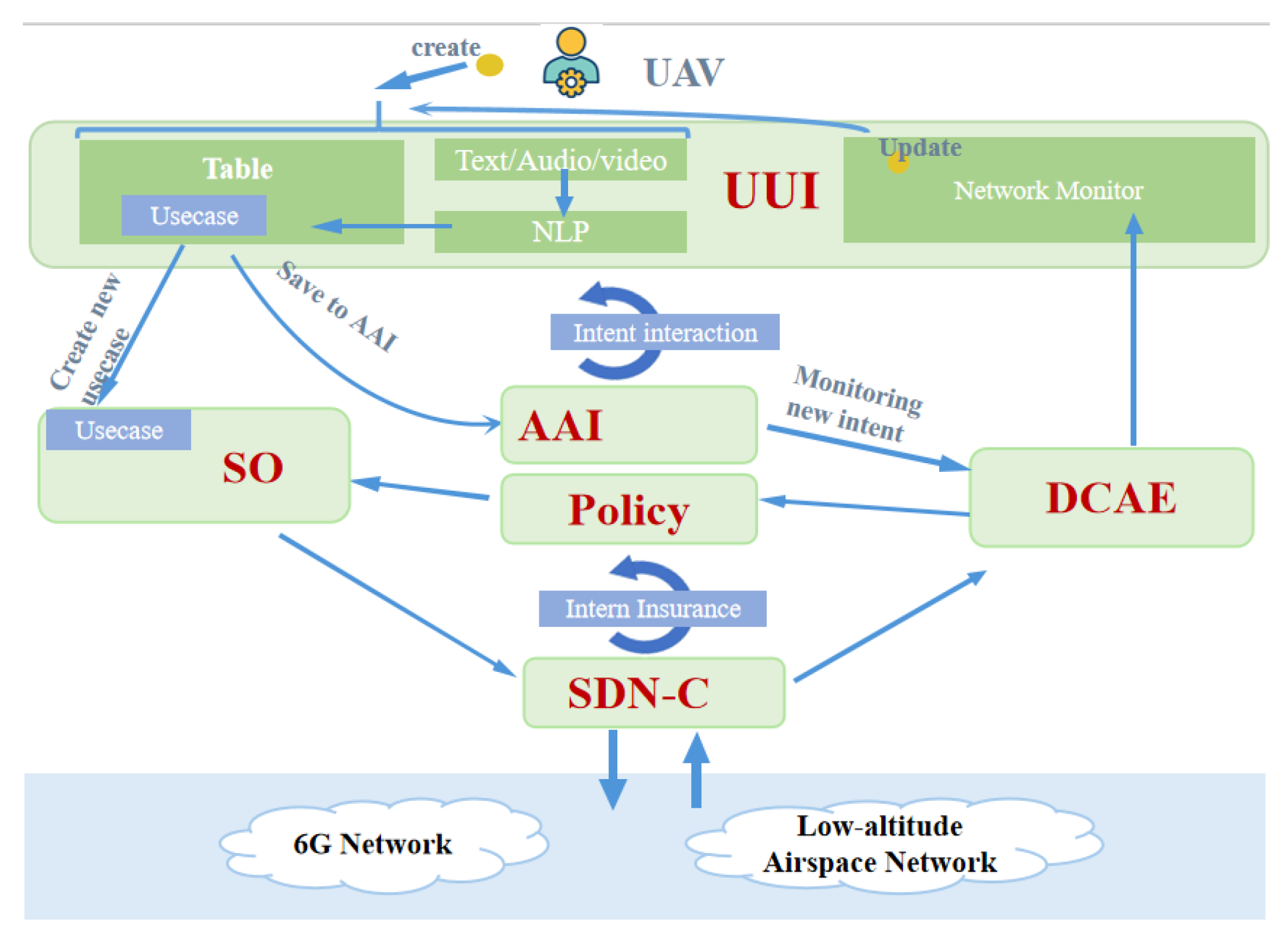
The outer closed loop involves two distinct types of data flows that support the creation and issuance of intent, as well as the modification and fulfillment of intent. The inner closed-loop structure is designed to ensure the realization of user intent and consists of four stages: M2A (Monitoring), A2D (Analysis), D2E (Decision), and E2M (Execution). Each phase includes specific tasks that are defined and executed by different modules within the solution architecture, such as the intent instance module, strategy module, service orchestration module, and others. These modules are specifically deployed and implemented within the digital twin airspace system [25].
Within the intent-driven drone network, the intent input and translation module is based on the Use-case User Interface (UUI). This module is responsible for parsing natural language inputs from users to extract the corresponding network intent requirements. These inputs may include voice commands or textual descriptions of business intent. After the natural language processing stage, the extracted intent is translated into relevant configuration parameters. The Software-Defined Network Controller (SDNC) and Service Orchestration (SO) modules then manage the Software-Defined Network (SDN) and execute the intent accordingly. They provide feedback to the Data Collection, Analytics, and Events (DCAE) system, which uses the intent verification module to assess whether the current network status meets the Service Level Agreement (SLA). Finally, the DCAE transmits the evaluation results back to the UUI, supporting decision-making by the digital twin system.
The intent instance management technology embedded in the intent-driven network enables seamless, closed-loop management of drone intentions and continuous monitoring of their operational status. When a change in a drone’s status is detected, the Data Collection, Analysis, and Event Correlation (DCAE) system sends a notification to the Use-case User Interface (UUI), prompting the digital twin system to intervene. In response, the digital twin system adjusts the intent instance parameters stored in the Active and Available Inventory (AAI) via the UUI. Following this adjustment, the AAI sends a notification back to the DCAE, instructing it to update the user intent storage, revise the parameters related to intent translation results, and access and update the storage containing drone status feedback information.
The natural language processing (NLP) capability within the UUI classifies drone intents into corresponding use cases or services, extracts relevant parameters from textual inputs, and populates them into automatically generated service request templates. These templates are then presented to the user for verification or modification. The service form serves as a standardized representation of user intent, clearly defining the service type, associated prerequisites, and Service Level Agreement (SLA).
The intent orchestration management component within the Use-case User Interface (UUI) interprets the parameters of user intent, translates them into an appropriate customer service blueprint, and subsequently forwards this information to the Service Orchestration (SO) module. The customer service blueprint serves as a declarative representation that clearly defines the services provided by the network operator to the customer.
SO then translates the customer service blueprint into a suitable service delivery framework within the transport network. This framework outlines the methodology for structuring and delivering services across the network. Following this, the Software-Defined Network Controller (SDNC) converts the service delivery framework into a corresponding network configuration schema, which is subsequently implemented in the physical network infrastructure.
The internal closed-loop mechanism for intent assurance consists of four distinct phases: monitoring, analysis, decision-making, and implementation. During the monitoring phase, the SDNC collects performance metrics related to drone operations and business execution data from the digital twin network controller, and then transmits this data to the Data Collection, Analysis, and Event Correlation (DCAE) system. The data collected by SDNC is determined based on the Service Level Agreement (SLA) parameters extracted from the user intent during the intent interpretation phase.
In the analysis phase, DCAE processes the monitoring data received from SDNC and provides feedback to the policy framework. This phase plays a crucial role in identifying anomalies in drone operations and triggering the policy framework to implement corrective actions.
The decision-making phase is policy-driven and utilizes data from the Data Collection, Analysis, and Event Correlation (DCAE) system to make closed-loop decisions. It then provides the Service Orchestration (SO) module with appropriate recommendations for executing service changes.
The execution phase involves standard Software-Defined Networking (SDN) orchestration and control workflows, in which SO and the Software-Defined Network Controller (SDNC) apply the updated drone network configuration to the physical network infrastructure.
All relevant data, including monitoring information, business models, network resources, and configuration details, are stored in the Active and Available Inventory (AAI) for future retrieval and sharing across different stages.
The configuration of the Intent-Driven Network (IDN) is mapped to the 6G physical network through the digital twin network.
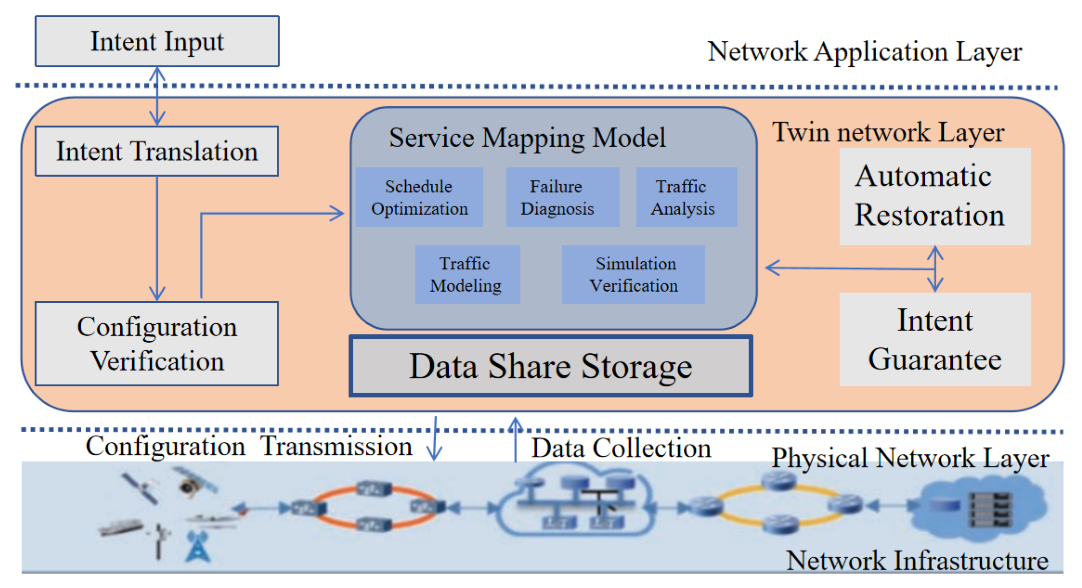
Figure 5 presents a reference framework for implementing IDN based on the Digital Twin Network (DTN) architecture. In this framework, the IDN infrastructure corresponds to the physical network layer in the DTN architecture. Key IDN functions, such as configuration verification, intent assurance, and automatic repair, are realized through various service mapping models in the twin network layer, ensuring real-time fulfillment of user intents originating from the network application layer [11].
Figure 5.
IDN architecture based on DTN.
-
Configuration Verification Based on Service Mapping ModelsAfter user intents are translated, a large number of network configurations that can be executed by the physical network are generated. Direct deployment of these configurations to the physical network may interfere with the normal operation of existing services, and the potential impact is often unpredictable. By leveraging the service mapping models of the digital twin network, these configurations can be pre-verified and simulated prior to deployment. This allows for the early detection of anomalies such as address conflicts, routing loops, and unreachable routes. Only after confirming that the configurations align with the user’s business intent and do not disrupt existing services are they deployed to the physical network.
-
Intent Assurance and Automatic Restoration Based on Service Mapping ModelsThe operational status of the physical network is collected and transmitted to the data storage layer of the digital twin network. The service mapping model continuously verifies whether the user intent is being fulfilled. When the network deviates from the intended behavior, intelligent technologies such as artificial intelligence (AI) can be employed for root cause analysis and to generate repair strategies. However, due to the current limitations of AI technologies in ensuring the reliability and effectiveness of these strategies, manual confirmation is typically required before deployment to the physical network, which can slow down the fault resolution process. By first validating the proposed repair strategies using the service mapping models of the digital twin network and confirming their correctness, these strategies can then be automatically deployed to the physical network via an automated configuration module. This approach not only enhances operational efficiency but also promotes the practical application of AI in network management [11].
In summary, intent-based networking can effectively utilize the architecture of digital twin networks to implement key functionalities such as pre-validation of network configurations and real-time assurance of user business intents. This integration facilitates the efficient deployment and implementation of intent-driven network systems.
5. Design and Architecture of System Model
5.1. Spectrum Efficiency Model of Drone Base Station
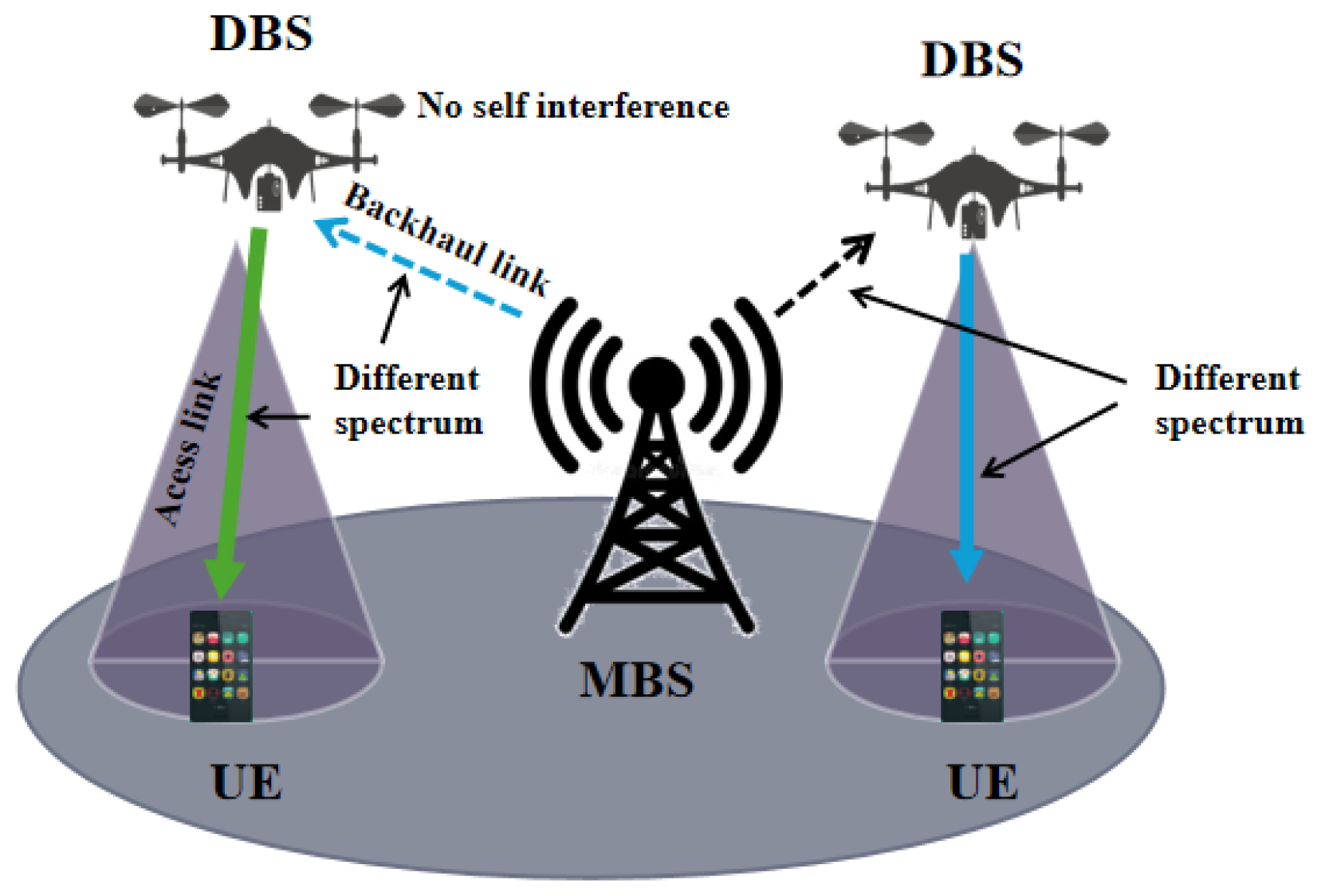
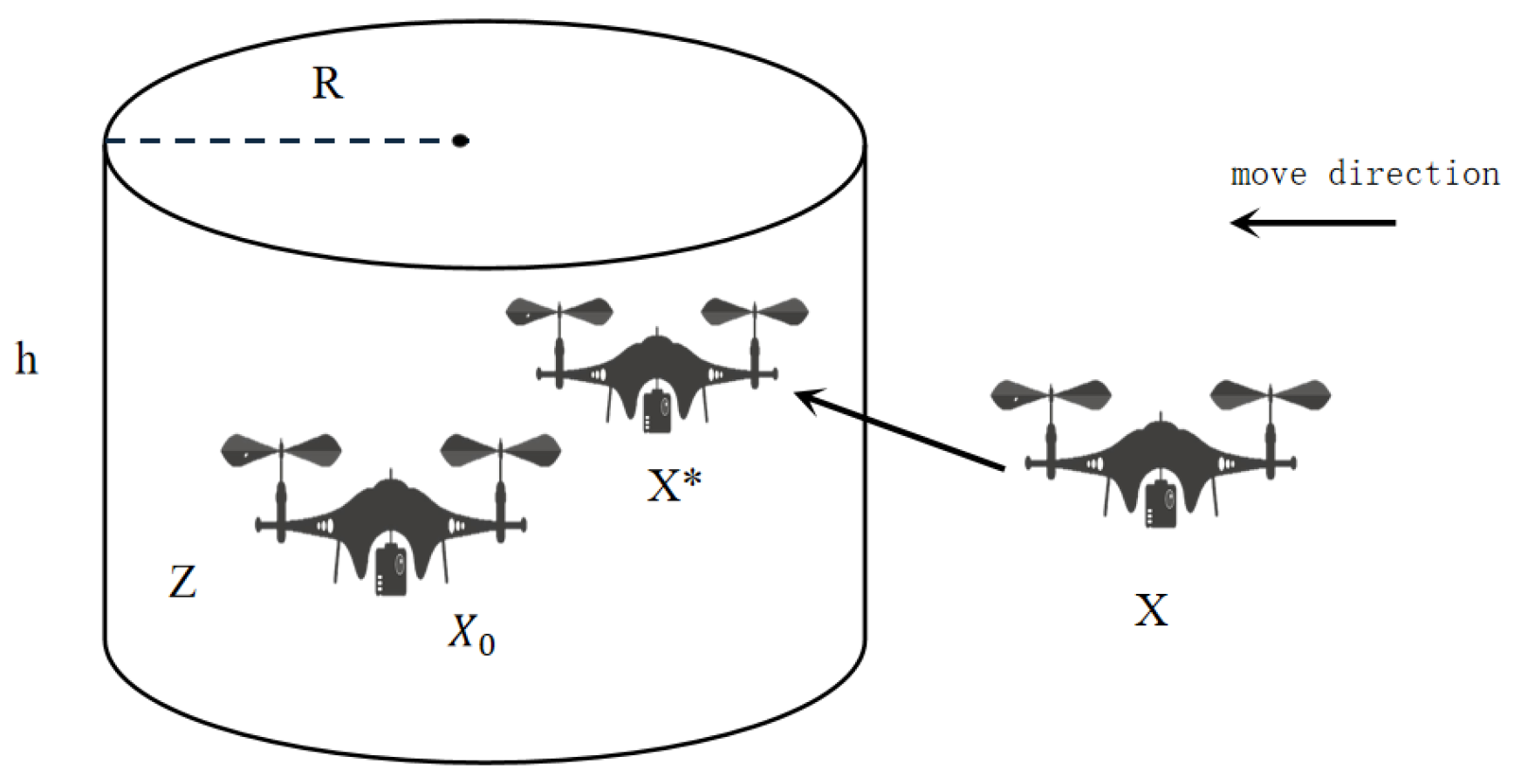
In the context of a self-organized network utilizing Drone Base Stations (DBS), a kind of base station mounted on the drones as the repeater between MBS (macro base station) and User Equipments (UEs) , we examine a scenario in which the DBSs fly along the air lines designed by the digital twin system and provide TDMA-based down-link service to static UEs that are distributed in the test region uniformly, resulting in interference among the UEs connected to the same DBS. To maintain the service connection stable, the DBSs move along the direct path toward a predetermined target location, as planned by the digital twin system to enhance spectral efficiency after the time slot of last UE is finished, or maintain their original positions. Throughout this process, the connections between the UEs and DBS are stable.
Figure 6.
UE communication with DBS
We denote the set of DBSs as and the set of UEs as . The set of UEs connected to and covered by the j-th DBS is represented by . The position of the i-th UE and the j-th DBS is denoted by and , respectively, where and .
The channel model is based on a probabilistic path loss model (PL). The Line of Sight (LoS) and Non-Line of Sight (NLoS) equations between the i-th User Equipment (UE) and the j-th Drone Base Station (DBS) are as follows [26]:
Let denote the distance between UE i and DBS j, c represent the speed of light in meters per second (m/s), and represent the carrier frequency in hertz (Hz). The mean additional path losses for Line of Sight (LoS) and Non-Line of Sight (NLoS) are denoted by and , respectively.
The probability of LoS between UE i and DBS j is given as follows:
where and are environment-related parameters, denotes the height of DBS j, and represents the horizontal distance between the i-th UE and the j-th DBS, is given by the following equation:
and distance between UE i and DBS j is given by the following formula:
The mean path loss of the DBS is is given by the following formula:
The denotes the received signal power of i-th UE from j-th DBS, expressed as
where is the transmission power (in dBm) of a DBS and is is given by the following formula:
where is the half-power beamwidth of the DBS antenna.
The i-th UE selects DBS , which is the DBS providing the maximum received signal power, to transmit the data.
The capacity of a DBS is shared equally among the connected UEs. We define as the number of UEs connected to the j-th DBS.
where is,
The data rate of the ith UE is as following formula:
where is the noise power and BW is the channel bandwidth.
And the data rate of jth DBS send is formulated as
The number of hovering DBS can cover the whole region is given by the following formula:
where is the whole acreage of test region.
The second method for DBS network coverage involves arranging the DBSs along the boundary of the test area and flying them vertically along the line of arrangement.
The test area can be conceptualized as a square. The number of DBSs is determined by the following formula:
The third method of DBS coverage is circular cruising. In this approach, the UAV flies along a circular path centered around the test area. The diagonal of the test area is used as the diameter of the UAV’s flight circle, and the coverage cells of each UAV do not overlap. As a result, the number of UAVs required for this scenario is given by the following formula:
Based on the above analysis, the deployment of DBS is determined by its coverage and data rate, which are closely related to the flight height and antenna beam width of the DBS.
5.2. Energy Consumption of Cruising Drone and Logistic Drone and the Energy Efficiency of Drone Base Station
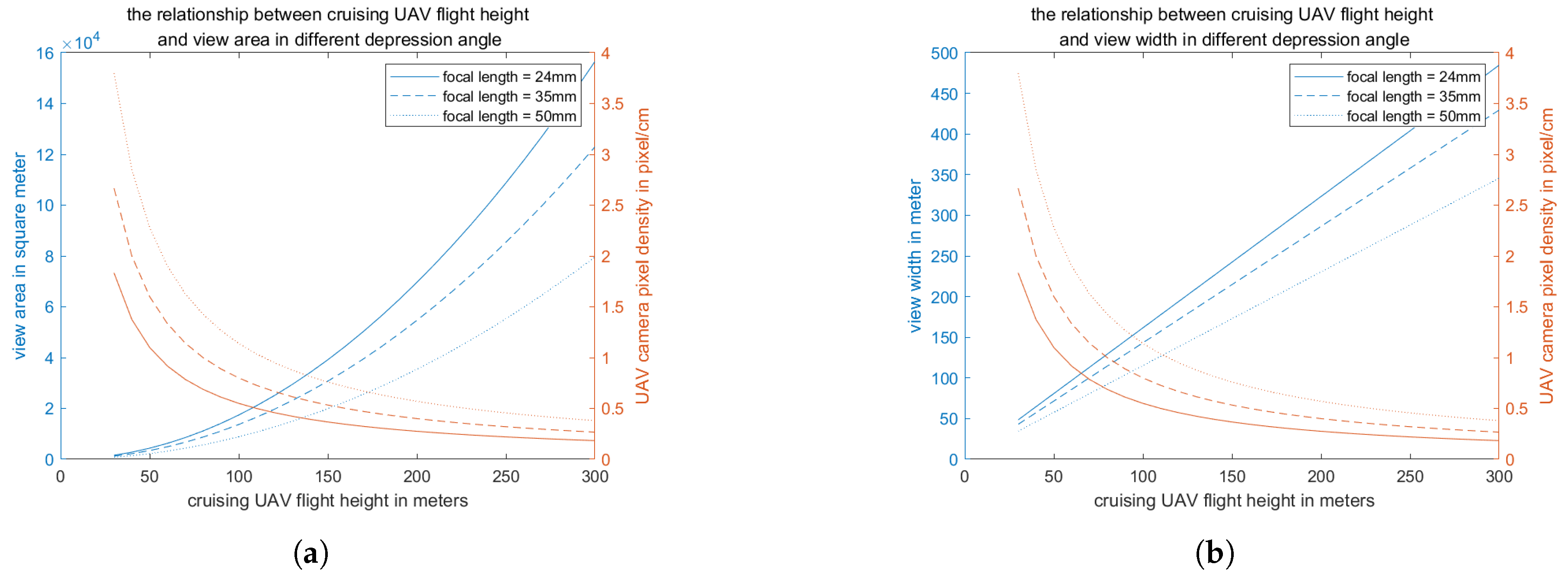
In aerial patrol scenarios involving UAV remote sensing, several parameters affect the UAV’s aerial cruising capabilities. These parameters include the UAV’s flight altitude, the Ground Sampling Distance (GSD) associated with cameras of different focal lengths, UAV power, the cruising flight path, and the width of the patrol area, among others.
The parameters of the aerial patrol UAV are obtained from the DJI website [27]. The GSD of the camera shots is denoted by the following formulas.
where h is height of UAV and fl is focal length of camera shot.
where is the depression angle of UAV, and w is the view width of UAV.
The pixel of the UAV camera is 8192*5460, so the shooting area of the UAV is is given by the following formula:[28]
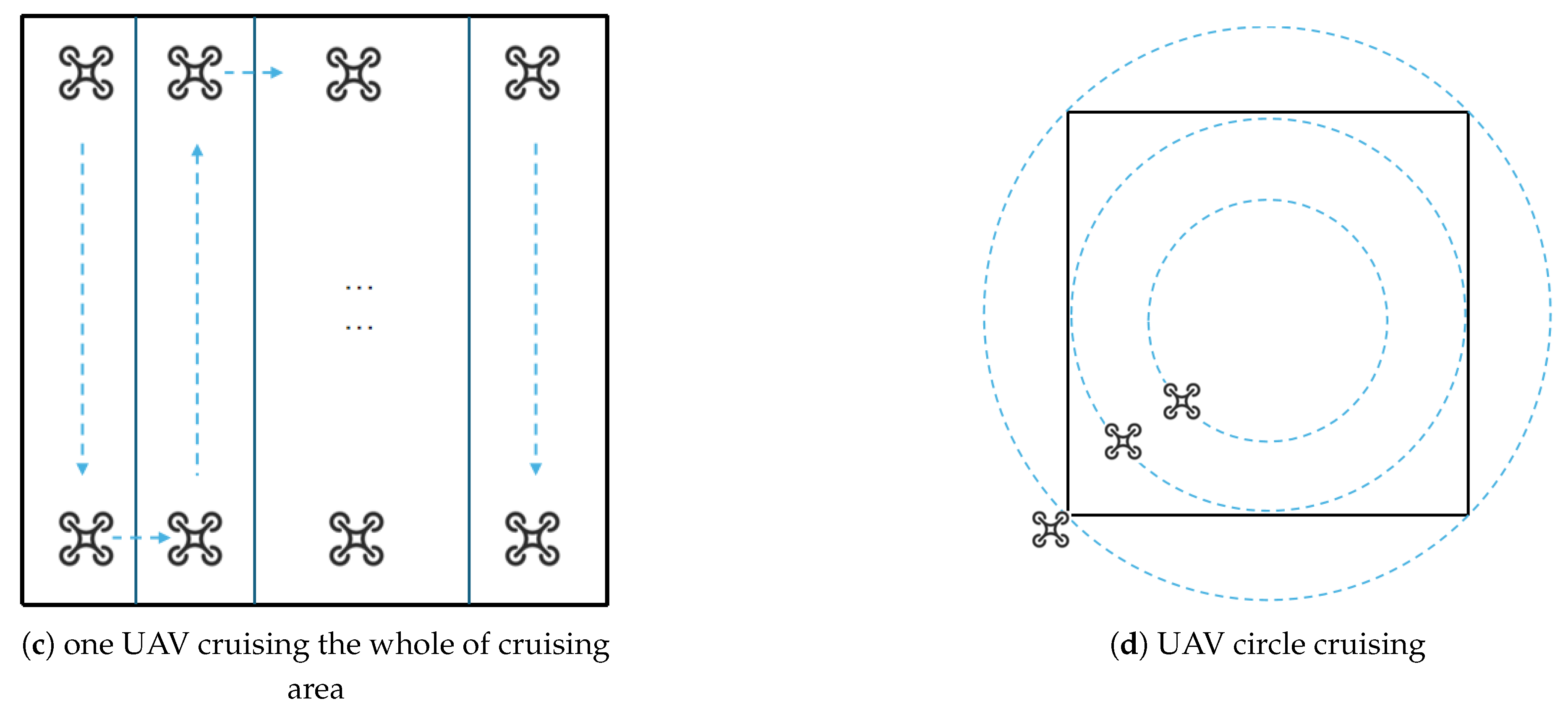
This study investigates four distinct navigation methods for covering the entire cruising area and evaluates the corresponding cruising time and energy consumption for each method.
Figure 7.
the four methods of UAV cruising
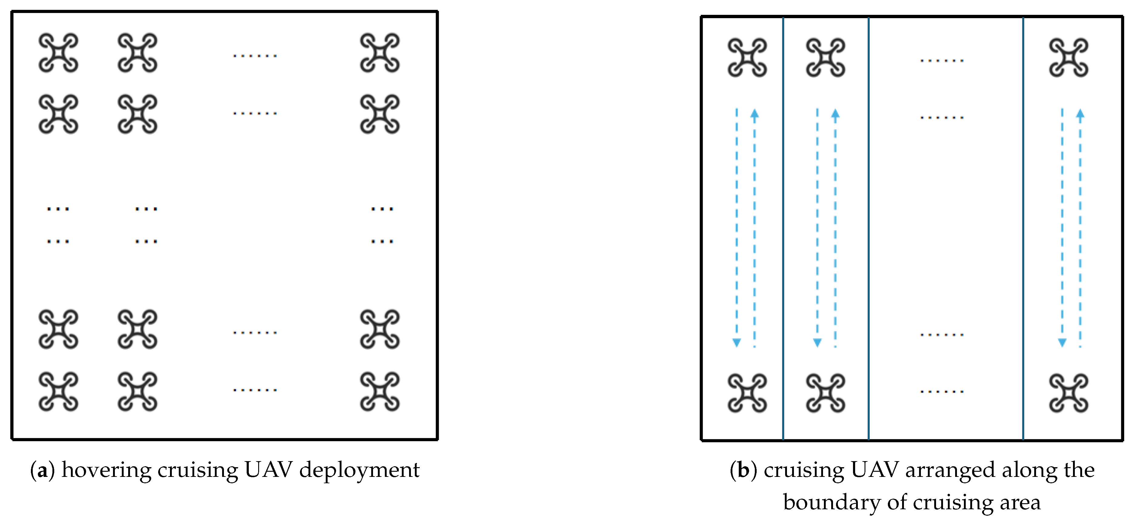
The first method involves UAVs maintaining stable hovering positions in the air to capture video footage. The required number of UAVs is given by the following formula:
where is the whole acreage of cruising area.
The second method involves positioning the UAVs along the perimeter of the designated cruising area, which is conceptualized as a square, and directing their movement vertically relative to the arrangement line. The number of UAVs is given by the following formula:
And the cruising time of the second way is given by the following formula:
where L is the edge length of the cruising area, and v is the speed of UAV.
The third approach involves deploying a single UAV to navigate the designated area, starting from one corner and moving along the perimeter. The UAV’s flight path follows a zigzag pattern, and its trajectory can be described by the following formula:
And the cruising time of the third way is as the following formula:
The fourth method of UAV cruising is referred to as circular cruising. In this method, the UAV flies along a circular path centered within the designated cruising area. The diagonal of the cruising area is used as the diameter of the UAV’s flight circle, ensuring that the fields of view of the UAVs do not overlap. As a result, the number of UAVs required for this scenario is given by the following formula:
To establish a unified perspective for multiple UAVs operating at the same altitude, this paper assumes that their angular speeds are consistent. The maximum angular speed is represented by the following formula:
where is the maximum linear velocity of UAV, which is limited by the UAV flying in the outermost circle air line.
and the cruising time of one circle is given by the following formula:
The cruising radius of ith UAV is given by the following formula:
and the linear speed of ith UAV is given by the following formula:
This study presents a comparative analysis of four distinct cruising methods, evaluated from two perspectives: the total cruising time over the entire test area and the corresponding energy consumption. The power requirements of a UAV consist of two components: the power needed for operating the electronic systems and the power required for flight.
The power of cruising UAV is given by the following formula [29]:
where W is the weight of the UAV, v is the UAV’s speed, is the UAV’s machine efficiency parameter, which is composed of the lift-to-drag ratio and the propeller efficiency, and e is the power of the UAV’s electronic components.
The energy of UAV cruising whole cruising area is given by the following formula:
where is the number of cruising UAV, is the cruising time of UAV.
In the context of a logistics UAV operational scenario, this paper assumes that a single logistics UAV delivers one package at a time, and its flight path is modeled as a straight line whenever feasible. The power requirements of the logistics UAV depend on the weight of the transported packages and the operating velocity of the UAV, as described by the following formula:
where is the package weight of UAV loaded.
The energy consumption of logistic drone is given by the following formula [29]:
where is the running time of each UAV.
From Formulas 33 and 34, it can be inferred that the energy consumption of a logistics UAV in the intent-driven airspace digital twin system is given by the following formula:
where is the total flight distance of each logistic UAV, which is given by the following formula:
where is the total horizontal distance between the starting points and destinations, is the total lifting times of each logistic UAV, which is typically 2 (one for picking up the package and one for delivery), and is the flight altitude of the logistics UAV.
In accordance with Formulas 35 and 36, and under the assumptions of this paper—that a single logistics UAV delivers one package at a time and that the flight path of the logistics operation is a straight line whenever feasible—it can be deduced that the total energy consumption of all logistics UAVs is given by the following formula:
Based on Formula 37, the energy consumption of the logistic UAV is divided into three components: the electronic component energy consumption , the horizontal movement energy consumption , and the lifting energy consumption .
Based on the aforementioned formulas, the voyage of a logistic UAV can be derived under different flight speeds and varying loads.
where is the fully charged energy, which is equal to the energy consumption of the logistics UAV when operating at maximum power for the maximum flight time.
Considering that the DBS is mounted on the same UAV platform as the cruising UAV and that its flight power is the same as that of the cruising UAV, the energy efficiency of the jth DBS is given by the following formula:
where the DBS speed is not limited by the cruising radius in the circle cruising scenario and same as the v.
5.3. Layered Deployment and Collision Conflict Risk of UAV
In the aforementioned scenario involving multiple intent-based task UAVs, we develop a spectral efficiency model for the base station UAV, a shooting area model for the cruising UAV, and power consumption models for both the cruising UAV and the logistics UAV.
In this section, we analyze the collision risk and probability associated with three types of intent-based tasks performed by UAVs operating in a mixed formation, as well as the collision probability when these UAVs fly individually. We propose a layered structure for the urban low-altitude airspace used by individually flying UAVs within a digital twin system (Figure 8), which is analogous to a network slice. This model supports UAV management and aims to reduce the risk of collision conflicts by creating an urban low-altitude airspace slice customized for different intent-based task UAVs, based on an intent-driven airspace digital twin system. Furthermore, as a control group, this study investigates the collision probability in an unstructured urban low-altitude airspace with a mixed flight structure.
Figure 8.
layered structure of low-altitude airspace based on UAV intent in digital twin system
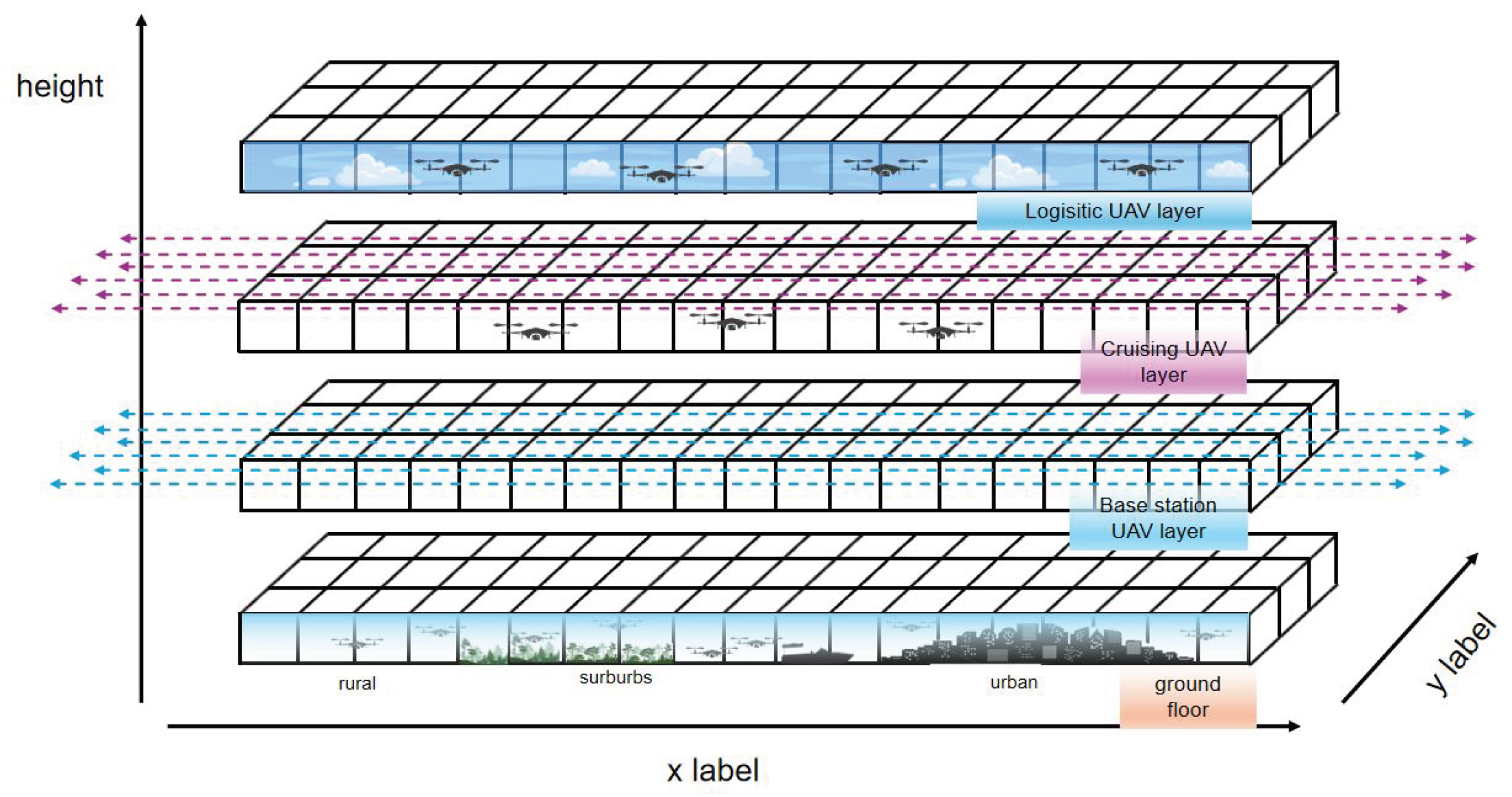
In the analysis presented in Section 4.4, concerning the DBS layer and the cruising UAV layer, it has been determined that the optimal structure for mitigating UAV collisions and enhancing energy efficiency is the layered-tube structure. This configuration enables UAVs operating in the DBS layer and the cruising layer to fly along designated tubes, as assigned by the intent-driven airspace digital twin system.
Collision conflicts in urban low-altitude airspace can be categorized into two types: the first involves collisions between buildings and UAVs, while the second refers to collisions among UAVs from any direction.
The occurrence of collisions between UAVs and buildings is related to the height distribution of the buildings. In this study, we assume that building heights follow a log-normal distribution, as described by the following formula [30]:
where is the mean height value and is standard deviation of log variable, is maximum building height. And is the whole acreage of testing area, is the building lot of testing area, the density of building is given by the following formula:
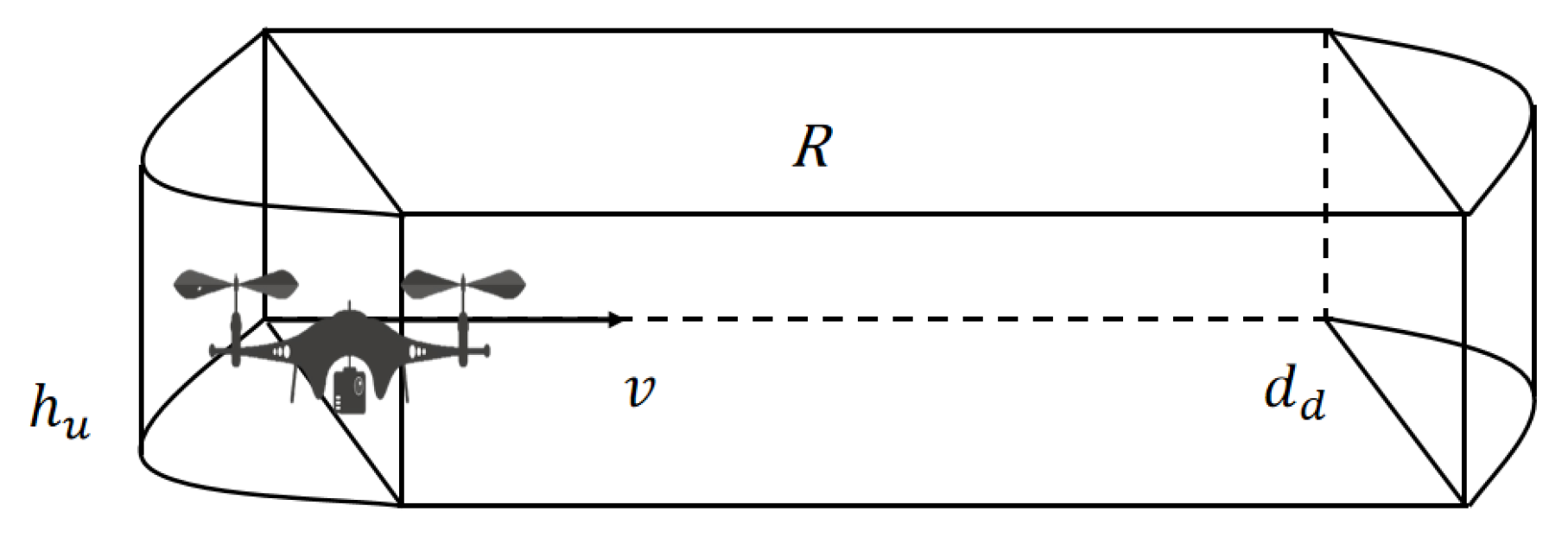
In the unstructured urban low-altitude airspace and in the logistic UAV layer of the intent-driven layered urban low-altitude airspace, the number of UAVs is less than or equal to the UAV capacity , as given by the following [30]:
where is the maximum width of the UAV, which is equal to the diameter of the UAV cylinder, is the radius of the UAV cylinder, is the layer height, which is equal to the maximum height of the UAV, R is the minimum safe distance, and V is the volume of the available urban low-altitude airspace.
The minimum security distance R is given by the following [30]:
where is the operation and delay time of the digital twin system and the UAV, is the collision avoidance time, is the volume of the UAV cylinder, D is the diameter of the minimum isolation area that any UAV must maintain from another UAV, and v is the flight speed of the UAV.
Figure 9.
minimum security distance R
The number of UAVs is a random variable ranging from 0 to , so the unit UAV capacity is given by the following formula:
The collision model between UAV and buildings is given by the following [30]:
where A is the contact area of UAV colliding with buildings.
The collision model between UAVs defines the minimum isolation area, denoted as Z, which is a cylinder with radius R and height h. The collision risk z, when a UAV enters the minimum isolation area of another UAV, is given by the following formula [30].
where T is the statistical time, is the UAV flying direction.
Figure 10.
minimum area of isolation Z
6. Results
In this paper, we examine three types of UAVs—namely, DBS, cruising UAVs, and logistic UAVs—within three categories of low-altitude airspace: urban, suburban, and rural. The designated test area spans 30 km × 30 km. It is important to note that the minimum flight altitude for UAVs varies across different countries and regions. For instance, in Hong Kong, Canada, and Japan, the minimum flight altitude is set at 30 meters; in the United Kingdom, it is 50 meters; and in Singapore, it is 60 meters. For the purposes of this study, a minimum UAV flight altitude of 30 meters is adopted. Additional parameters are detailed in Table 1.
Figure 11 illustrates the relationship between front-haul data rates and the number of User Equipment (UE) units covered by DBS at varying altitudes. It is observed that the data rate decreases as altitude increases, while the number of UEs covered increases with altitude, with a notable intersection occurring at an altitude of 90 meters.
Figure 11.
the relationship between DBS front-haul data rate and UE number and DBS height.
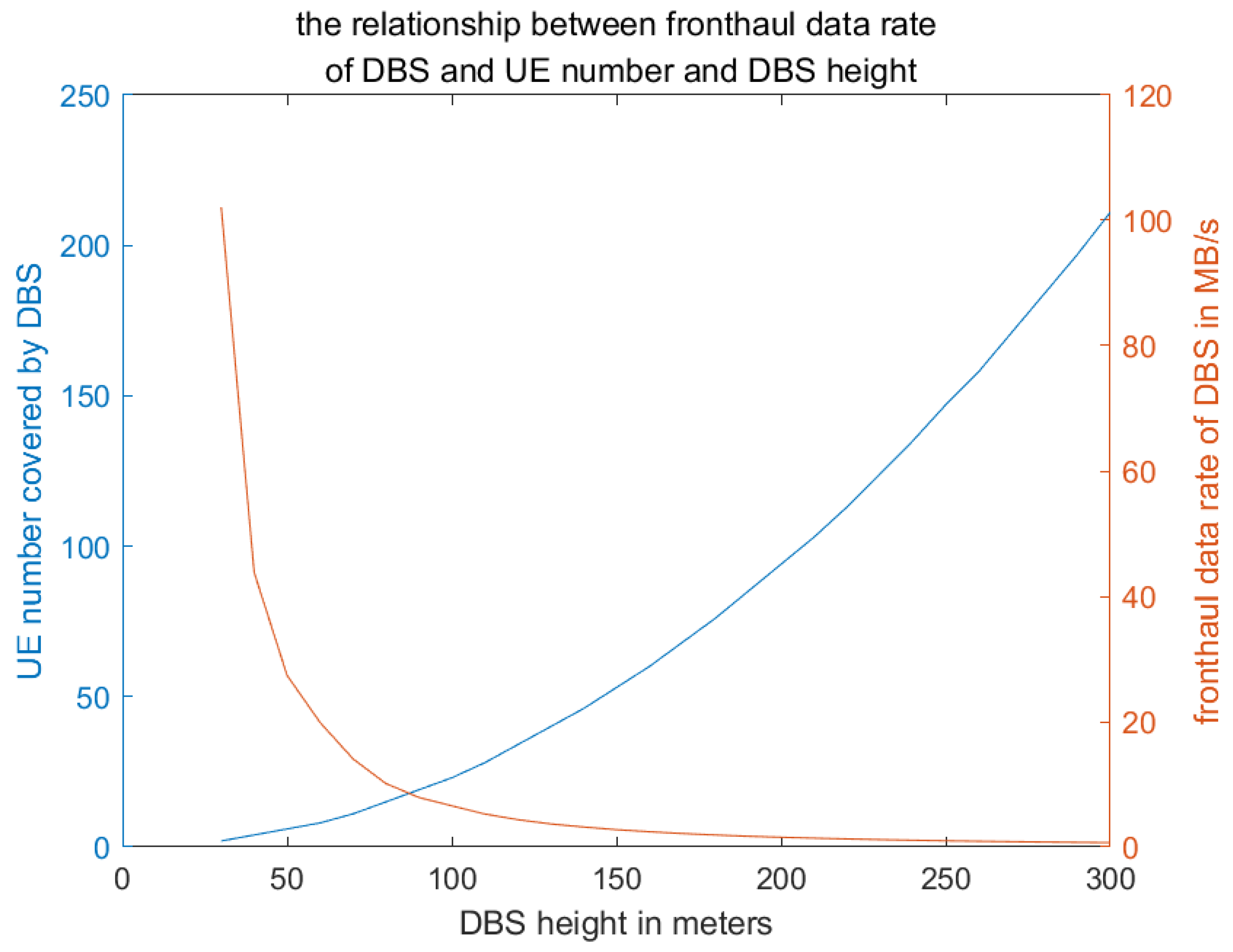
Figure 12 presents the number of DBS units operating within the designated airspace of the test area, comparing three distinct deployment strategies. The analysis reveals that the maximum number of DBS is achieved at an altitude of 30 meters, where the highest count of circular cruising DBS is 29. In contrast, the maximum number of DBS operating along the vertical boundary of the test area reaches 400, and the maximum number of hovering DBS is recorded at 16,743. As altitude increases, the demand for DBS decreases, with the minimum requirements observed at an altitude of 300 meters. Specifically, the minimum number of circular cruising DBS is 3, the minimum number of DBS cruising along the vertical line of the boundary is 41, and the minimum number of hovering DBS is 167.
Figure 12.
the number of DBS cover the whole test area in different heights in 3 deployment ways
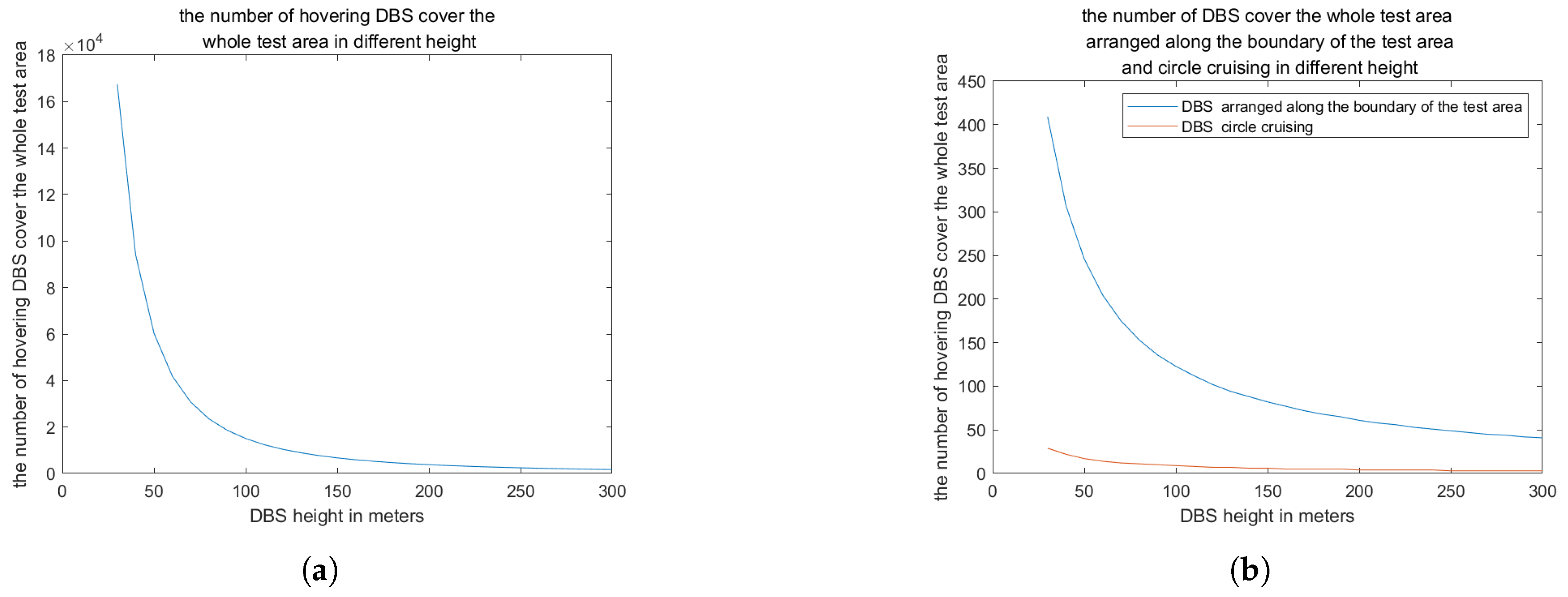
Figure 13 illustrates that as the DBS height increases, the front-haul data rate decreases, thereby reducing the energy efficiency of the DBS. Without considering the movement energy consumption, the energy efficiency of hovering DBS is significantly higher than that of cruising DBS.
Figure 13.
the energy efficiency of DBS in different heights in hovering and cruising
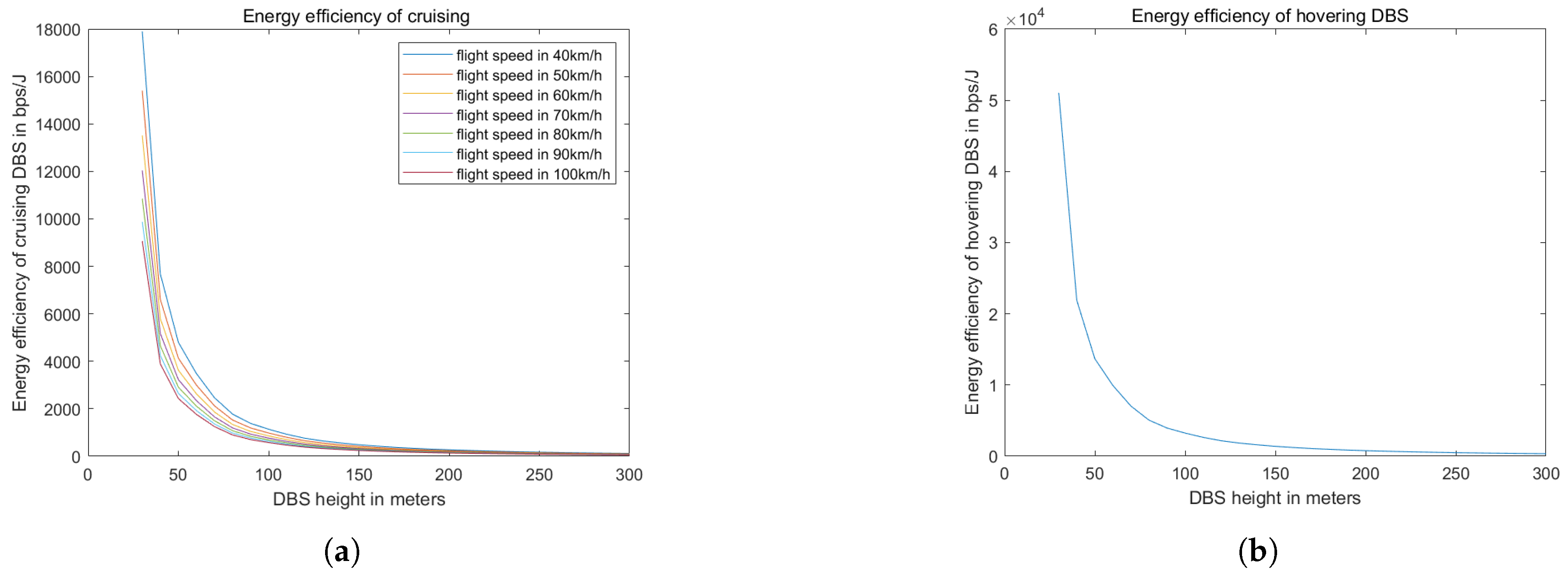
Figure 14 illustrates that as the cruising altitude of the UAV increases, both the view width and the view area expand; however, the pixel density decreases. The optimal balance between the field of view and the resolution of the video, across three focal lengths, is observed at altitudes ranging from 110 to 170 meters.
Figure 14.
the relationship between cruising UAV flight height and view area and view width
Furthermore, as depicted in Figures 15, 16, 17, and 18, a comparative analysis of energy consumption among various UAV cruising methods—namely, hovering, circular cruising, straight-line-round cruising along the boundary of the cruising area, and a single UAV covering the entire area—reveals significant differences. The time required for a single UAV to cover the entire area is considerably longer than that for circular and straight-line-round cruising methods. Notably, the energy consumption associated with hovering is substantially higher than that of the other three methods. Among the three, circular cruising appears to consume the most energy compared to straight-line-round cruising. Specifically, circular cruising requires 10.5 minutes to cover the entire area, while straight-line-round cruising at the maximum UAV flight speed takes 18 minutes. Additionally, the number of UAVs required for circular cruising is significantly lower than that for straight-line-round cruising. It is also observed that, at lower flight speeds, the energy consumption of straight-line-round cruising exceeds that of circular cruising. Moreover, energy consumption decreases as the UAV flight altitude increases, due to the reduced number of UAVs needed to cover the entire area at higher altitudes. However, the rate of decrease in energy consumption slows when the UAV’s cruising height exceeds 170 meters. As the UAV flight speed increases, the time required to cover the entire area decreases, which in turn reduces the energy consumption of the UAV’s electronic components and, consequently, the overall energy consumption. The analysis of the figures indicates that the most energy-efficient method for UAV cruising within the test area is circular cruising at altitudes below 170 meters.
Figure 15.
the relationship between hovering cruising UAV height and total energy consumption of the cruising UAV system in different depression angle.
Figure 15.
the relationship between hovering cruising UAV height and total energy consumption of the cruising UAV system in different depression angle.
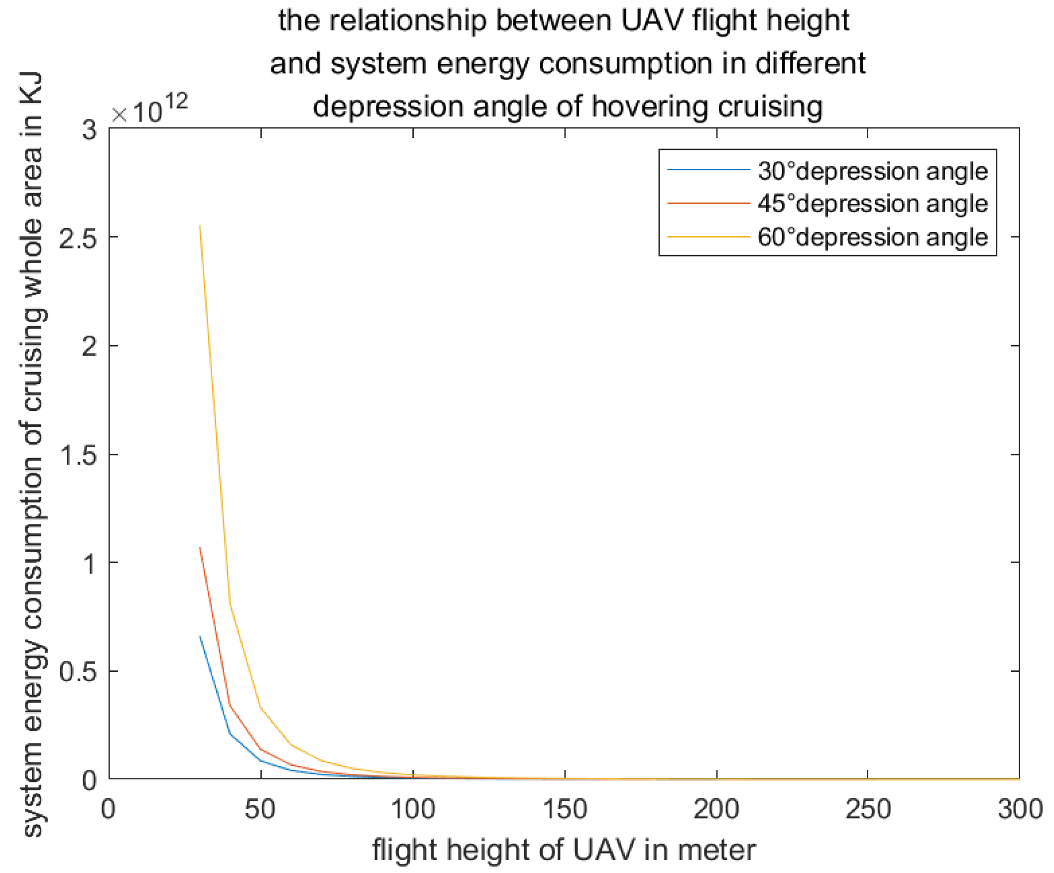
Figure 16.
the relationship between circle cruising UAV height and total energy consumption of the cruising UAV system in different depression angles.
Figure 16.
the relationship between circle cruising UAV height and total energy consumption of the cruising UAV system in different depression angles.
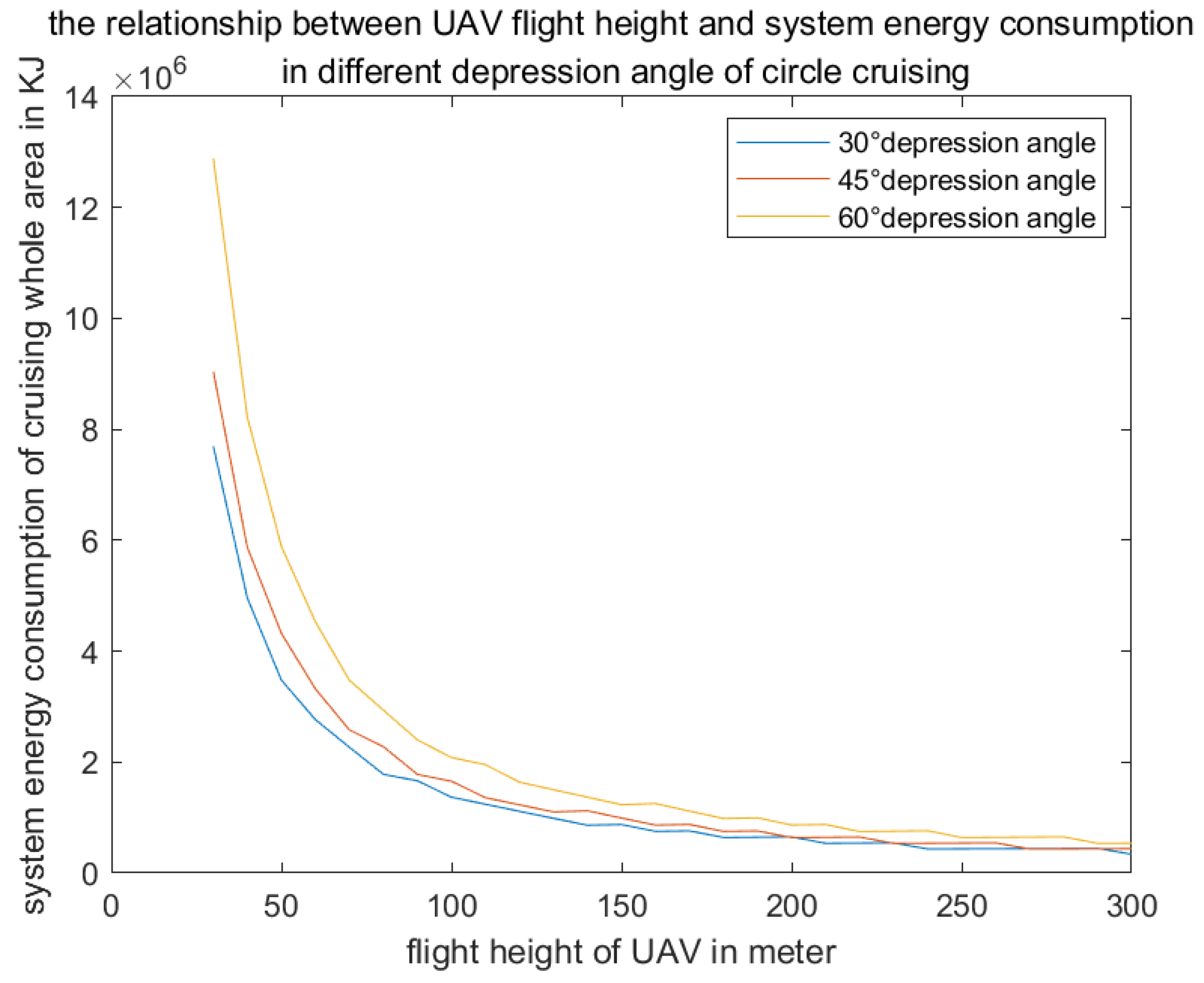
Figure 17.
the relationship between cruising UAV flight height and total energy consumption of the straight-line-round cruising UAV system in different depression angles.
Figure 17.
the relationship between cruising UAV flight height and total energy consumption of the straight-line-round cruising UAV system in different depression angles.

Figure 18.
the relationship between cruising UAV flight height and total energy consumption of the one cruising UAV cruising whole test area in different depression angles.
Figure 18.
the relationship between cruising UAV flight height and total energy consumption of the one cruising UAV cruising whole test area in different depression angles.
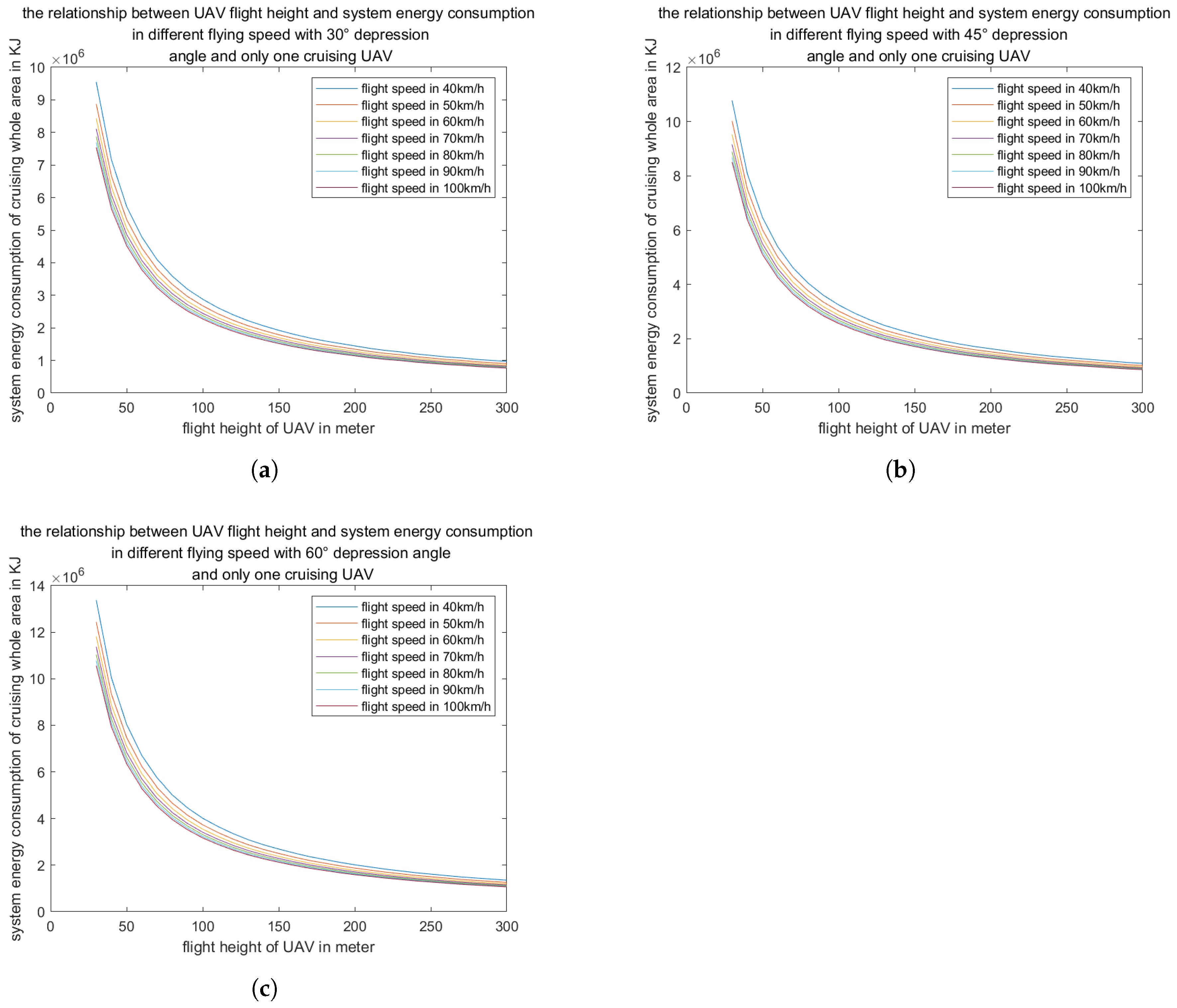
Figure 19 illustrates that as the speed and payload of logistic UAVs increase, their maximum flight distance decreases. Specifically, logistic UAVs carrying lightweight cargo can achieve a maximum flight distance exceeding 20 km when operating at maximum speed and under maximum load. As a result, the operational altitude of logistic UAVs may be higher than that of DBS and cruising UAVs. However, when the payload exceeds 1.5 kg, the maximum flight distance decreases significantly with increasing load. Therefore, it is recommended that the payload of logistic UAVs should not exceed 1.5 kg.
Figure 19.
the relationship between logistic UAV speed and maximum flight of the logistic UAV in different loads.
Figure 19.
the relationship between logistic UAV speed and maximum flight of the logistic UAV in different loads.
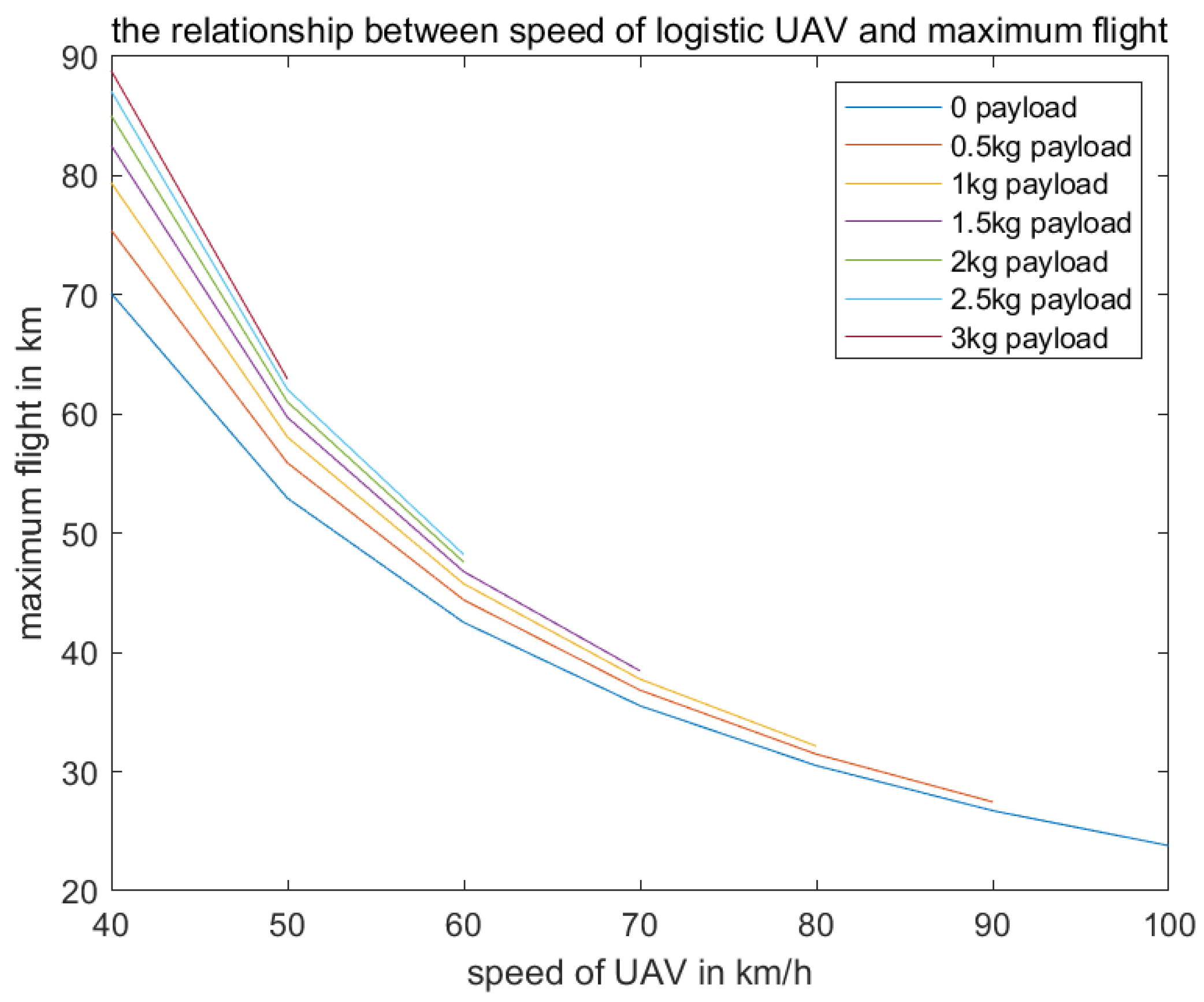
Based on the aforementioned analysis, we have established airspace layers within the low-altitude intent-driven airspace digital twin system, categorized according to three types of UAV intent: the base station layer at 30–90 meters, the cruising layer at 110–170 meters, and the logistics layer at 190–300 meters. To assess the risk of collision conflicts in intent-driven layered airspace management, we have used unstructured low-altitude airspace as the control group.
Figure 20 illustrates the relationship between the speed of UAVs and the risk of collision conflicts. The data presented in the figure indicate that the collision risk remains relatively consistent across different areas. However, it is observed that as the UAV speed increases and the diameter of the minimum isolation area decreases, the risk of collision conflicts also increases.
Figure 20.
the relationship between UAV speed and collision conflict risk of UAV in unstructured low altitude airspace.
Figure 20.
the relationship between UAV speed and collision conflict risk of UAV in unstructured low altitude airspace.
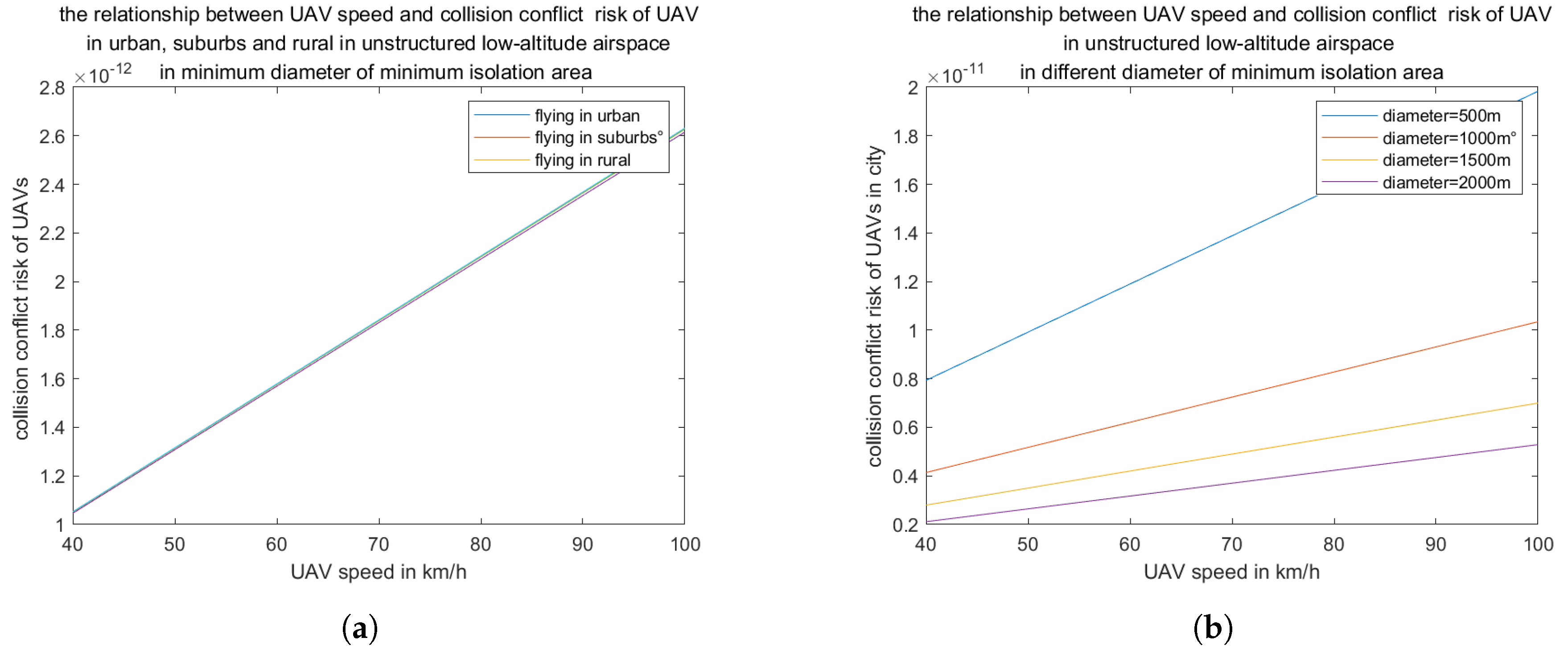
Figure 21 further demonstrates that as the UAV speed increases, the collision conflict risk between the UAV and buildings also increases. Furthermore, the collision risk in urban areas is significantly higher than in suburban areas and greater than in rural regions. In addition, the minimum scurity distance only affects the capacity of UAV and is not related to the collision conflict risk between the UAV and buildings in this study.
Figure 21.
the relationship between collision conflict risk of UAV and building and UAV speed in unstructured airspace.
Figure 21.
the relationship between collision conflict risk of UAV and building and UAV speed in unstructured airspace.
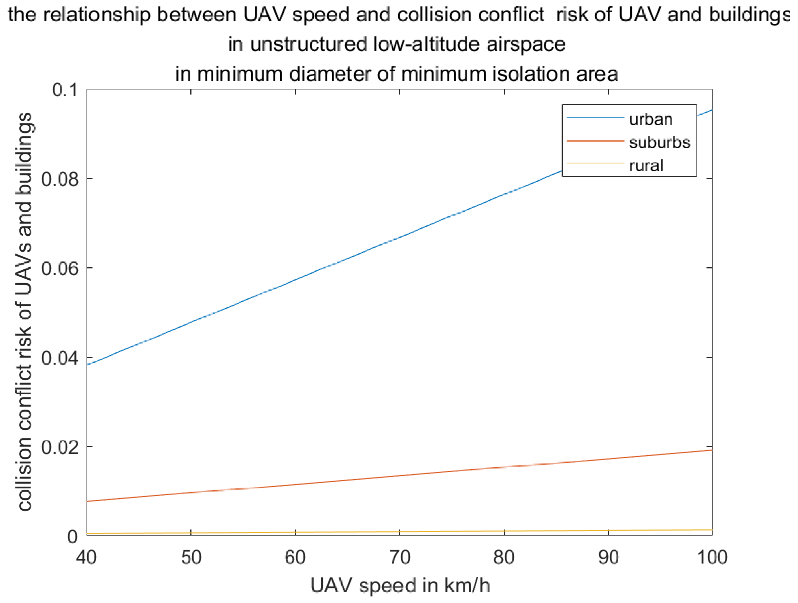
Figure 22 illustrates that within the DBS layer of the layered low-altitude airspace, an increase in UAV speed and a decrease in UAV height are associated with a heightened risk of collision conflicts between the DBS and buildings. Furthermore, as the distribution function of building heights decreases sharply from urban to suburb and rural areas, the risk of such conflicts also decreases. Similarly, as building density declines from urban to rural areas, the likelihood of collision conflicts diminishes. Additionally, the figure suggests that circular cruising patterns may reduce the risk of collision conflicts compared to vertical cruising along the arrangement line, especially given the relatively low number of DBS present.
Figure 22.
the relationship between UAV speed and collision conflict risk of DBS and buildings in DBS-layer airspace in different area with different cruising way.
Figure 22.
the relationship between UAV speed and collision conflict risk of DBS and buildings in DBS-layer airspace in different area with different cruising way.
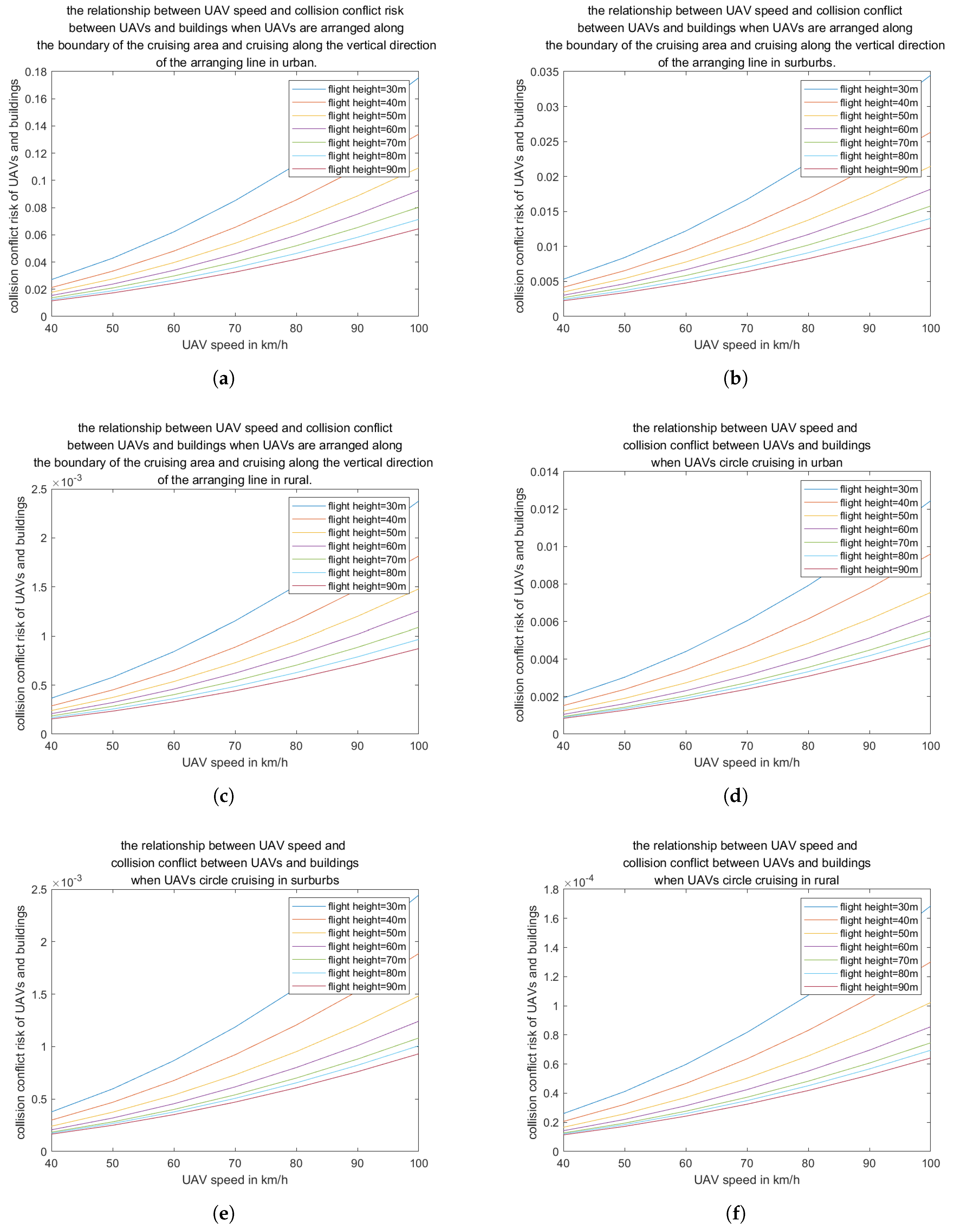
Figure 23 illustrates that within the layered low-altitude airspace, the risk of collision conflicts for UAVs in the logistics layer is reduced compared to the unstructured low-altitude airspace shown in Figure 20(b). This reduction in risk can be attributed to the smaller volume of the logistics layer relative to the overall test airspace, which results in a lower UAV capacity. Furthermore, the flight altitude of UAVs in both the cruising layer and the logistics layer exceeds the maximum height of surrounding buildings, thereby minimizing the potential for collision conflicts between UAVs and buildings. Additionally, the design of the cruising flight layer further reduces the likelihood of UAV-to-UAV collisions.
Figure 23.
the relationship between logistic UAV speed and collision conflict risk in logistic layer
Figure 23.
the relationship between logistic UAV speed and collision conflict risk in logistic layer
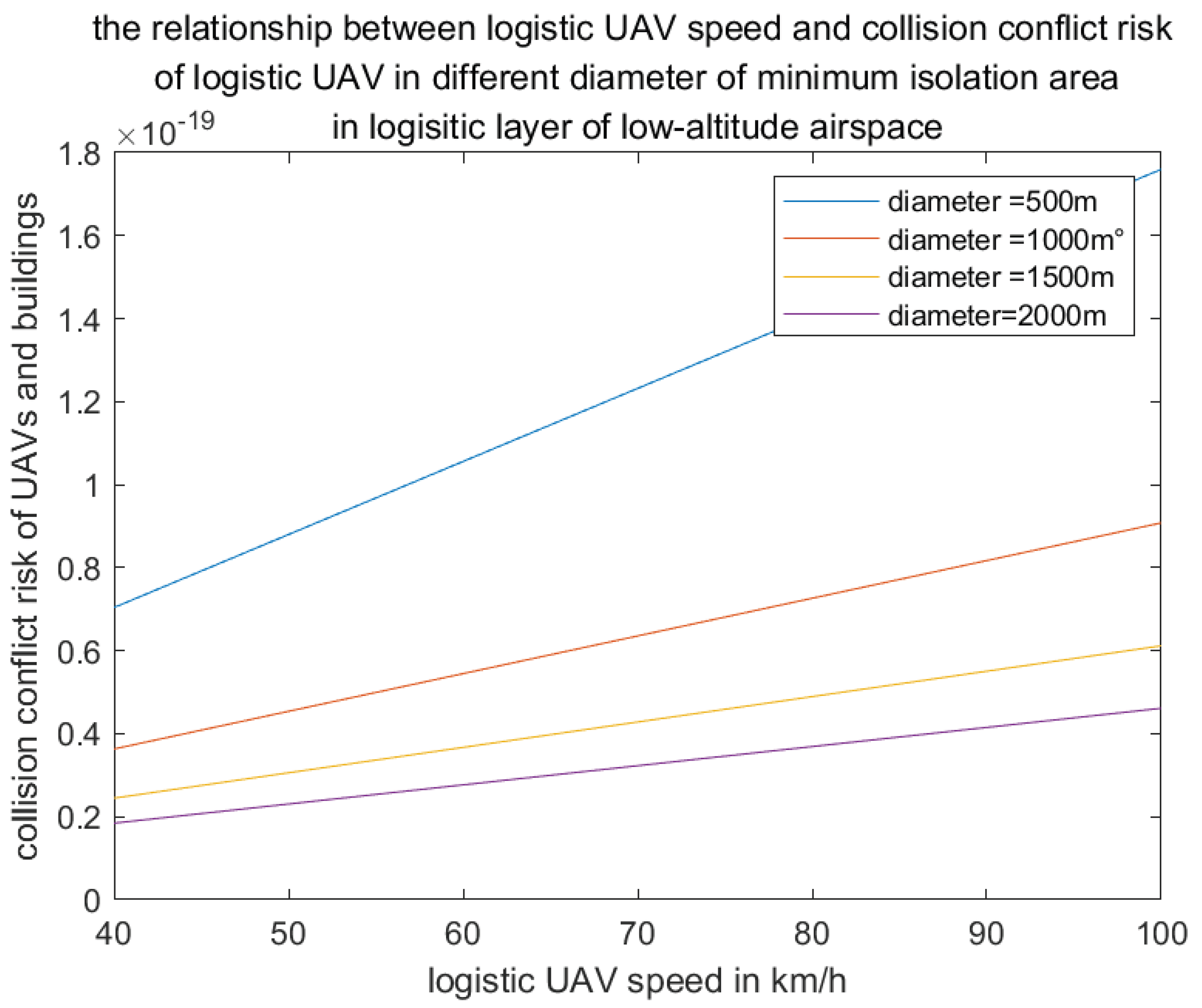
7. Conclusions
This study investigates and simulates the performance of multiple-intent UAVs and the associated risk of collision conflicts within a low-altitude airspace digital twin system. We have designed a low-altitude layered digital airspace based on UAV intent, aiming to reduce the risk of collisions between UAVs and buildings, as well as among UAVs themselves, while maintaining optimal UAV performance. The simulation results demonstrate significant optimization.
It is concluded that DBS circular cruising in the 30–90 meter altitude airspace at 40–50 km/h can maintain high energy efficiency and low collision risk. Cruising UAVs flying in a 30-degree depression angle within the 110–170 meter altitude airspace can cover the entire test area with low energy consumption and no collision risk. Logistics UAVs flying in the 190–300 meter altitude airspace show little difference in performance compared to their maximum flight altitude when ascending or descending in higher layers. However, when the load of a logistics UAV exceeds 1.5 kg, its flight performance decreases sharply. Therefore, the load of a light-weight logistics UAV should not exceed 1.5 kg.
Compared with unstructured airspace, the risk of collision conflicts among layered UAVs is reduced from to , and the risk of collision between layered UAVs and buildings is reduced from to , respectively.
Author Contributions
Conceptualization, X.L. and Y.C.; methodology, X.L.; software, X.L.; validation, X.L., J.T. and Y.Z.; formal analysis, X.L.; investigation, Y.C.; resources, J.T.; data curation, Y.Z.; writing—original draft preparation, X.L, Y.C. and J.T.; writing—review and editing, X.L.and Y. Z.; visualization, Y. C.; supervision, X .L.; project administration, X.L. All authors have read and agreed to the published version of the manuscript.
Funding
This research received no external funding.
Institutional Review Board Statement
Not applicable.
Informed Consent Statement
Not applicable.
Data Availability Statement
The data of simulation is obtained from the references without generating new data.
DURC Statement
Current research is limited to the low-altitude airspace management, which is beneficial share benefits and does not pose a threat to public health or national security. Authors acknowledge the dual-use potential of the research involving drones conflict and confirm that all necessary precautions have been taken to prevent potential misuse. As an ethical responsibility, authors strictly adhere to relevant national and international laws about DURC. Authors advocate for responsible deployment, ethical considerations, regulatory compliance, and transparent reporting to mitigate misuse risks and foster beneficial outcomes.
Acknowledgments
Not applicable.
Conflicts of Interest
The authors declare no conflicts of interest.
References
- NASA NTRS. Overview of NASA’s Next Generation Air Transportation System (NextGen) Research. Available online: https://ntrs.nasa.gov/citations/20100025034 (accessed on 20 August 2025).
- Sesar joint undertaking. Delivering the digital European sky. Available online: https://www.sesarju.eu/ (accessed on 10 July 2025).
- Research Report on Market Prospect Forecast of Chinese Unmanned Aerial Vehicle Industry in 2024 https://www.seccw.com/Document/detail/id/26598. (accessed on 10 January 2024)2024.
- CHEN Zhijie, ZHU Yongwen , LIU Yang. Management strategy of the urban UAV based on digital airspace system. Journal of Civil Aviation University of China, 2023, 41(3), pp. 8-12.m.
- ZHANG Hong-hai, YI Jia, LI Shan, LIU Hao, ZHONG Gang. Review on research of low-altitude airspace capacity evaluation. Journal of Traffic and Transportation Engineering, 2023, 23(6), pp. 78-93.
- LI Lingling, HAN Ruiling, ZHANG Xiaoyan. Identification and capacity evaluation of available space in urban low-altitude airspace: A case study of Beijing. Science, Technology and Engineering, 2021, 21(19), pp. 9.
- QI RuoYu, FAN Jingwen. Technical Comparison of Low-Slow Small UAV Detection and Countermeasure Systems. Internet Technology, 2021, 11(6), pp. 88-89.
- XIE Hua, SU Fangzhen, YIN Jianan, HAN Site, ZHANG Xinyu. Network modeling and refined management of UAV flight conflicts in complex low altitude airspace. Acta Aeronautica et Astronautica Sinica 2023, 44(18), pp. 328226.
- WANG Qiqi, MO Haoying, HU Jiangmin, MOU Mingming. Research on Network Optimization Method Based on Digital Twin. Audio Engineering 2021, 45(1), pp. 52-54.
- ZHOU Yaoquan, LIU Zehua, ZENG Lei. Research on Urban Governance Schemes Based on Drones. Proceedings of the 5th System Engineering Academic Conference - System Engineering in the Digital Intelligence Era 2023.
- SUN Tao, ZHOU Cheng, DUAN XiaoDong, LU Lu. Digital Twin Network (DTN): Concepts, Architecture, and Key Technologies. ACTA AUTOMATICA SINICA 2023, 47(3), pp. 569-582.
- Lin Fengcheng, Qiu Chenhui, Yang Jiazhu. An intent-driven service hierarchical experience guarantee solution. Telecommunications Engineering Technology and Standardization, 2022, 35(11), pp. 12-16.
- ZHOU Yangcheng, YAN Shi, PENG Mugen. Intent-driven 6G radio access network. Chinese Journal on Internet of Things, 2020, 4(1), pp. 73-79.
- Wang Jianwei, You Jiang, Wan Min, Gu Jingliang. Low-altitude UAV detection and tracking algorithms in complex backgrounds. High Power Laser And Particle Beams 2023, 079001, 1–12. [Google Scholar]
- Deng Junwen. Real Time Multi-Drone Detection and Tracking for Low-Altitude Defense. Parts and Desgin, 2023, 571(6), pp. 20-23.
- Zhang Zhuo, Sun Baofen. Drone Detection and Countermeasure Technology. Internet Application, 2023, 44(8), pp. 85-86.
- ZHAO Weidong, WANG Tingji. Research on Unmanned Aerial Vehicle Detection Techniques. DIGITCW Technology Study 2021, 07, 15–24. [Google Scholar]
- Kashif Mehmood, H. V. Kalpanie Mendis, Katina Kralevska, and Poul E. Heegaard. Intent-based Network Management and Orchestration for Smart Distribution Grids. 2021 28th International Conference on Telecommunications (ICT), 2021, pp. 355-360.s.
- Yoonseon Han, Jian Li, Doan Hoang, Jae-Hyoung Yoo, and JamesWon-Ki Hong. An Intent-based Network Virtualization Platform for SDN. IEEE IEEE/IFIP International Conference on Very Large Scale Integration 2016, pp. 353-358.
- Jinyong (Tim) Kim, Eunsoo Kim, Jinhyuk Yang, Jaehoon (Paul) Jeong, Hyoungshick Kim, Sangwon Hyun, Hyunsik Yang, Jaewook Oh, Younghan Kim, Susan Hares, and Linda Dunbar. IBCS: Intent-Based Cloud Services for Security Applications. IEEE Communications Magazine, 2020, pp. 45-51.
- Aris Leivadeas, Matthias Falkner. VNF Placement Problem: A Multi-Tenant Intent-Based Networking Approach. 24th Conference on Innovation in Clouds, Internet and Networks (ICIN 2021), 2021, pp. 143-150.
- Mehdi Bezahaf, Marco Perez Hernandez, Lawrence Bardwell, Eleanor Davies, Matthew Broadbent, Daniel King and David Hutchison. Self-Generated Intent-Based System. 2019 10th International Conference on the Network of the Future (NoF), 2019, pp. 138-140.
- Muhammad Faraz Hyder and Tasbiha Fatima. Towards Crossfire Distributed Denial of Service Attack Protection Using Intent-Based Moving Target Defense Over Software-Defined Networking. IEEE Access, 2021, pp. 112792-112804.
- Aris Leivadeas, Matthias Falkner. VNF Placement Problem: A Multi-Tenant Intent-Based Networking Approach. 24th Conference on Innovation in Clouds, Internet and Networks (ICIN 2021), 2021, pp. 143-149.
- Intent-Driven Autonomous Intelligent Network White Paper. Available online: https://www.g6gconference.com/ (accessed on 15 December 2024).
- A. Akarsu and T. Girici. Resilient Deployment of Drone Base Stations. 2019 Internation Symposium on Networks, Computers and Communications, 2019, pp. 1-5.
- DJI. Available online: https://www.dji.com/ (accessed on 15 August 2025).
- LUO Sanqiang, ZHU Hongwei, ZHU Jin, ZHAO Tao. Research on the application of UAV remote sensing technology in river patrol scenes. Technology Innovation and Application, 2024, 2(4), pp. 193-196.
- LING Chen. UAV Path Planning Considering Energy Consumption and Marine Predator Algorithm. Automation Technology and Application, 2024, 43(1), pp:5-13.m.
- YANG Yonggang, ZHAO Chenzhi. Collision risk probability between buildings and UAVs in low-altitude mission airspace Research. Scientific and Technological Innovation, 2024, (10), pp:48-52.
Figure 1.
Digital twin network
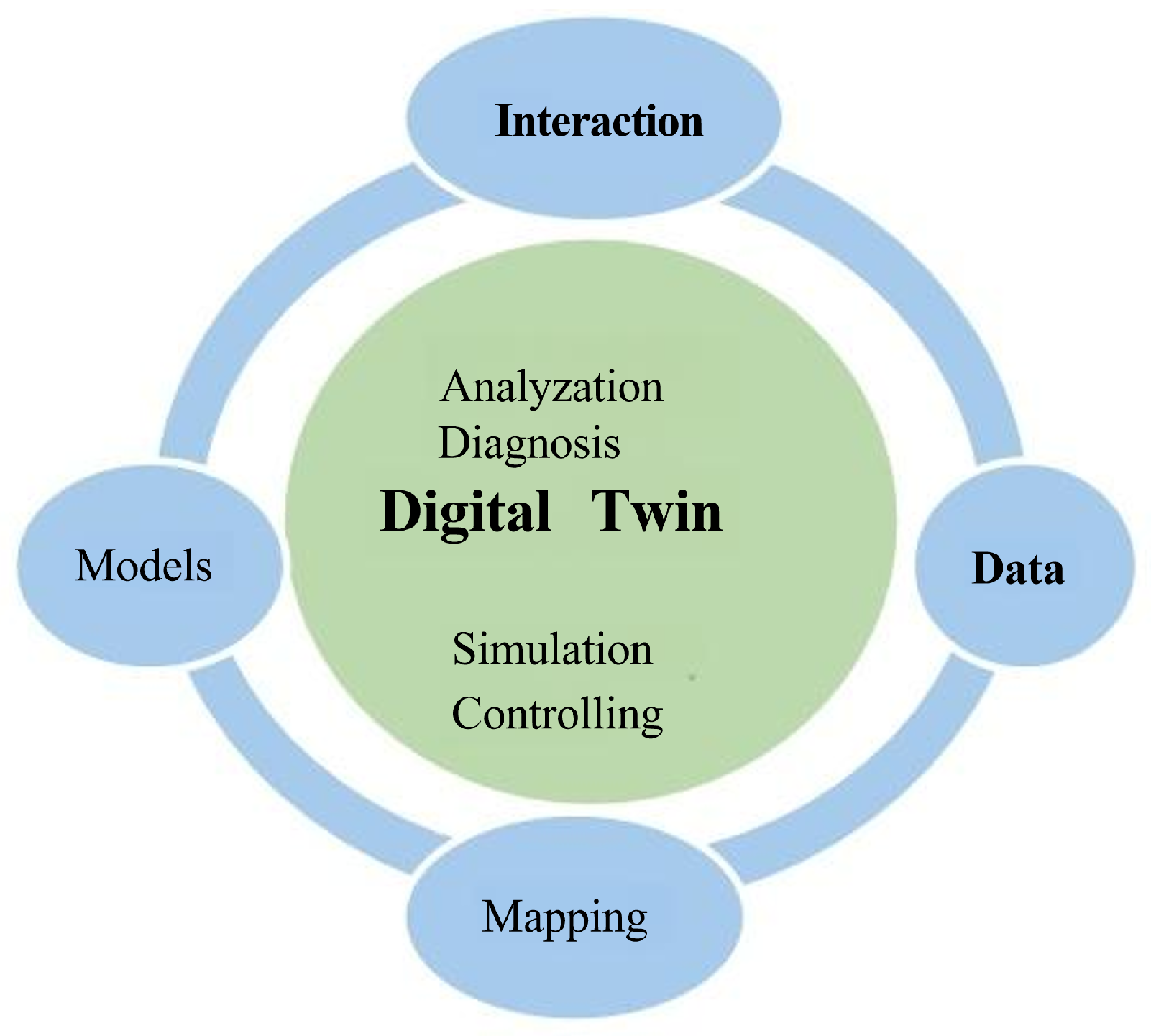
Figure 2.
Digital twin network architecture
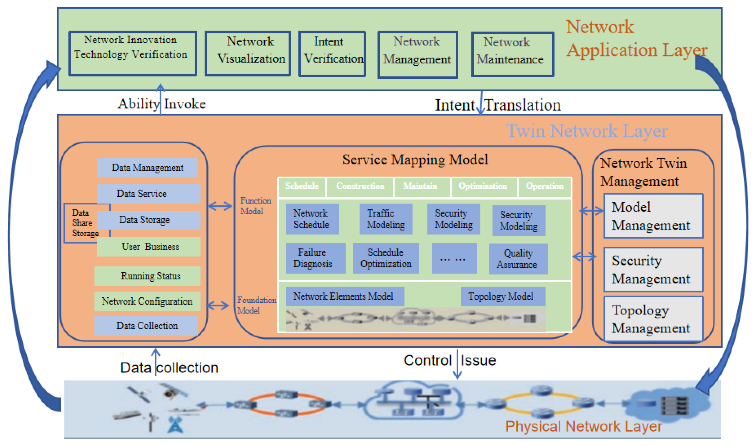

Table 1.
This is a table caption.
| Parameter | Parameter Meanings | Value |
|---|---|---|
| carrier frequency | ||
| c | speed of light | |
| additional mean loss of LoS | ||
| additional mean loss of NLoS | ||
| environment constant | ||
| environment constant | ||
| antenna beamwidth | ||
| thermal noise power | ||
| bandwidth of DBS | ||
| transmission power of DBS | ||
| h | UAV flight height | |
| acreage of test region | ||
| L | boundary length of test region | |
| focal length of camera | ||
| depression angle of UAV | ||
| v | UAV speed | |
| W | UAV weight | |
| package weight of UAV load | ||
| e | power consumption | |
| machine efficiency | 3 | |
| maximum flight power | ||
| max flight time | ||
| std. dev. of log variable | ||
| mean of log variable | ||
| max building height (urban, suburban, rural) | ||
| building density (urban, suburban, rural) | ||
| max UAV width (diameter) | ||
| UAV radius | ||
| digital twin delay | ||
| collision avoiding time | ||
| UAV volume | ||
| D | minimum isolation diameter | |
| A | building collision contact area | |
| T | statistical time | |
| UAV flight direction |
Disclaimer/Publisher’s Note: The statements, opinions and data contained in all publications are solely those of the individual author(s) and contributor(s) and not of MDPI and/or the editor(s). MDPI and/or the editor(s) disclaim responsibility for any injury to people or property resulting from any ideas, methods, instructions or products referred to in the content. |
© 2025 by the authors. Licensee MDPI, Basel, Switzerland. This article is an open access article distributed under the terms and conditions of the Creative Commons Attribution (CC BY) license (https://creativecommons.org/licenses/by/4.0/).
Copyright: This open access article is published under a Creative Commons CC BY 4.0 license, which permit the free download, distribution, and reuse, provided that the author and preprint are cited in any reuse.


