
Submitted:
21 June 2024
Posted:
24 June 2024
You are already at the latest version
Abstract
Leaky-wave antennas (LWAs) represent a recent class of radiating systems, first appeared in the second half of the past century. Initially treated with a certain dose of skepticism due to the apparent non-physical nature of supported wave solutions, LWAs have so far deeply evolved from the original configuration of slotted metallic lossy waveguide and adapted to a huge number of practical application fields, from microwave to millimeter waves and even up to the terahertz frequency range. Due to physics of relevant working principle, LWAs are often found in planar and low-profile configurations, being critically required in many cutting-edge applications, where device miniaturization, scaling and integration are required. Here we propose a review of some of the most recent and perspective array-fed 2-D LWAs, selecting two of most widespread categories in applications, Fabry–Perot Cavity Antennas (FPCAs) and Bull’s-Eye Antennas (BEAs), discussing and illustrating some advanced features recently proposed.
Keywords:
Leaky-wave antennas
; planar geometries
; phased arrays
; Fabry–Perot Cavity Antennas
; Bull’s Eye Antenna
; Orbital Angular Momentum
; polarization reconfiguration
; environment scan
; near-field focusing.
1. Introduction
Two-dimensional (2-D) leaky-wave antennas (LWAs) belong to the class of traveling wave antennas. Based on planar geometries either metallic or metal-dielectric, their working principle depends on the excitation on the antenna aperture of cylindrical leaky waves, excited by a simple nondirective source and propagating with a complex leaky radial wavenumber (with respect to cylindrical coordinates reported in Figure 1), being and the radial leaky phase and attenuation constants, respectively [1].
Leaky waves in uniform open waveguides constituted by ordinary materials are improper solutions of the relevant dispersion equations, i.e., they do not satisfy the Sommerfeld radiation condition at infinity [2,3,4], whereas they may be either proper or improper in periodic open waveguides [5], depending on the operating frequency. In any case, their physical validity is restricted to certain angular ranges within which they are exponentially damped and hence negligible at infinity; nevertheless, if they are effectively excited in frequency ranges where they are both fast () and weakly attenuated () with respect to the free-space wavenumber , they may dominate the antenna aperture field, providing an asymptotic representation of the relevant waveguide continuous spectrum and thus, via Fourier transformation, of the antenna radiation pattern [6,7].
The condition , crucial for the leaky-wave to dominate the aperture field, implies that the complex wave provides a large aperture illumination, in terms of the free-space wavelength . An immediate consequence is that, considering the properties of the Fourier transform, the radiation pattern is characterized by high elevation directivity.
A cylindrical leaky wave with radiates a conical scanned beam with beam angle , whereas when a broadside beam () is produced, [6]. Two important formulas for the beam angle and the 3-dB elevation beamwidth , valid for the case of a scanned beam are (1):
where the hat indicates the normalization of radial phase and attenuation constants, and respectively, by the free-space wavenumber . (Additional general pattern-related formulas may be found in [6,8] and [9], for a great variety of circumstances encountered in applications). The normalized radial wavenumber typically shows a frequency-dispersive behavior. Therefore, as a consequence of (1), to perform an elevation scan (and also potentially vary the elevation beamwidth) it is sufficient to vary the operating frequency [10,11,12].
The aim of the this work is to introduce two-dimensional (2-D) leaky-wave solutions with multiple feeders, i.e., array-fed 2-D LWAs. In such designs the attractive features of LWAs in terms of elevation directivity, pattern reconfigurability, and feed simplicity are combined with the additional degrees of freedom provided by the possibility of independently controlling the multiple sources in amplitude and phase, thus shaping the associated array factor. In particular, in this paper we will focus on two types of planar and low profile 2-D LWAs. In section II we present array-fed implementations of a class of uniform or quasi-uniform structures known as Fabry–Perot Cavity Antennas (FPCAs), whereas section III is devoted to radially periodic Bull’s-Eye Antennas (BEAs), presenting for both classes the most recent developments and perspectives.
2. Fabry–Perot Cavity Antennas
Fabry–Perot Cavity Antennas represent a class of resonant radiating systems. The historical roots of such structures are found in the last quarter on 19th century, when Fabry–Perot interferometers where developed, presenting at the time exceptional, unprecedented spectroscopic resolving powers [13]. The idea behind FPCAs, first proposed in [14], stems from the intuition that such a high optical wavelength resolution could be turned into angular resolution and hence high elevation directivity in the microwave range.
A plane-parallel cavity represents the core of the structure, enclosed by a metal ground plane and a partially reflective sheet (PRS), either uniform (e.g., a high-permittivity superstrate) or quasi-uniform (e.g., a periodic metal screen with spatial periods small with respect to the free-space wavelength), [15,16] (see Figure 1).
Even if the first approach describing the possibility to obtain a collimated beam at broadside was based on geometrical optics [14], the leaky-wave method has been proven to be both more physically insightful and effective in the design procedure [17]. In this perspective, the antenna feeders have just the role of efficiently exciting cylindrical leaky waves, hence they are typically simple, nondirective radiating elements such as dipoles, slots or patch antennas. The choice of the source, however, directly affects the azimuthal dependence as well as the polarization of the pertinent excited field [6].
2.1. Fabry–Perot Cavities and Far-Field Twisted Beams
Recently, FPCAs have been employed in a number of cases to launch waves carrying orbital angular momentum (OAM) [18]. While the polarization manipulation is a widespread topic, OAM engineering has recently gained interest due to potential applications to telecommunications, radar, imaging and sensing due the fact that electromagnetic waves with different orbital angular momenta are completely orthogonal, greatly enlarging the bandwidth of a possible channel, [19,20].
OAM transporting waves have been introduced in [21] for optical frequencies, rapidly finding interests in other bands, from radiofrequencies up to X and gamma-rays. Field twists are due to phase distribution depending from the azimuth coordinate with the form , i.e., there is no phase invariance on planes orthogonal to the main axis of power flux supposed to be, with no loss of generality, the z axis. The mode index ℓ is an integer, known as , its sign determines the handedness of the vortex and the relevant number of twists in a period.
The interest in OAM-carrying waves mainly depends on the fact that, unlike the circular polarization being able to provide only right-handed or left-handed rotation, a potentially unlimited number of waves with different indices of ℓ can be generated.
In a real-world scenario, OAM applications have actually limitations principally due to phenomena of strong attenuation and fading [22,23]. One distinct issue consists in finding a suitable way for a successful OAM launch. It has been demonstrated that the most versatile method consists in circular arrays, which can be properly phased to obtain a radiated field transporting a given momentum. By switching from an inter-element phase difference value to another, the order of the momentum is then varied. An issue for the latter scheme in the free-space configuration consists in the fact that, for every OAM beam, the pointing direction is markedly dependent on the topological charge ℓ, since the dependence of the far field on the elevation angle is given through the expression in (2):
where is the complex amplitude coefficient impressed to feeders, the free-space wavenumber, a is the radius of the array and represents the first kind Bessel function of ℓ-th order.
When switching from an order to another, i.e., changing the value of the integer ℓ, due to the form of Bessel functions, the maximum of the pattern moves to different angles, for fixed values of array radius a and free-space propagation constant . This aspect has been overcome by considering concentric circular arrays, one for each OAM order [24], increasing the overall number of feeders and the total complexity of the system. An alternative solution in order to reduce the number of sources has been addressed in [18] where the effect of source embedding in Fabry–Perot cavities is considered. In a resonant environment, a simple planar circular array of coaxial cables, approximated by vertical electrical dipoles (VEDs), is inserted through the ground plane of the cavity (consider [18] for the complete antenna structure). This choice is largely motivated by the fact that, according to (1), the main-beam features are mainly established by the radial wavenumber of the operating leaky mode (3):
in which corresponds to the complex transverse propagation constant [1], represents the scalar equivalent admittance normalized by the free-space impedence [25], the value of dielectric constant of the material filling the cavity and h the relevant height.
Observing the numerator in (3), the is still present but the nulls of the denominator, which appear due to the resonant nature of the cavity, mitigate the shifting effect due to OAM order selection, at least for low values of the ℓ integer. Equivalently, such a condition can be explained by the dominance over the entire field of a singular spectral leaky contribution on the antenna aperture. Conversely, from the expression in (3), one may observe that a radiation null is always located at broadside [6,26,27]. Assigning to the VEDs a proper phasing scheme, it is possible to obtain a radiated field of a desired orbital angular order, selected among 0, , without affecting the beam angle.
It is worth to stress that the latter result is obtained reducing the TEM mode to a slow wave regime filling the cavity with a low-dielectric-constant material, and exciting the mode in a fast-wave regime, with the relevant radial attenuation constant small enough to make the field dominant on the aperture, as shown in the dispersion diagram in Figure 2.
It is demonstrated that, referring to parameters chosen as in [18], a single dominant leaky solution is obtained around 18 GHz, whose relevant far-field pattern in the elevation plane is weakly affected by the chosen OAM order imposed by phasing, as shown in Figure 3.
The aspect of efficient feeding, then, crucial to design efficient radiating systems has been evaluated, considering that, due to azimuthal symmetry of the feeding network, the relevant scattering matrix is circulant, meaning that a single row is enough to determine it completely. In Figure 4 the magnitudes of the scattering parameters are reported, demonstrating values lower than the -18 dB threshold, hence confirming excellent excitation performance.
2.2. Fabry–Perot Cavities for Far-Field Polarization Reconfiguration
Fabry–Perot Cavity Antennas find applications in polarization reconfigurability and beam scanning. Circular-polarization demand is rapidly growing in civil, medical and military sectors, due to a number of advantages, such as, the absence of orientation matching, resilience to multipath fading, and possibility to overcome obstacles on the propagation path, [28]. Linear to circular conversion is a solution which may avoid complex geometries to produce conditions of phase quadrature and magnitude equality on both horizontal and vertical field components. Once again, leaky-wave antennas and low complexity standards required by relevant feeders may effectively simplify the design.
In [29], by independently exciting a couple of TM and TE leaky modes, simple polarization-reconfigurable elevation scan is obtained. The relevant feeding network consists in a coaxial cable inserted through the ground plane to obtain a VED-like source, whereas by etching in the ground plane radial slits in a circular configuration a source equivalent to a vertical magnetic dipole (VMD) is obtained (refer to [29] for an exhaustive geometrical description and parameters). The cavity optimization [30] obtains a large frequency span (approximately from 12 to 19 GHz in the case considered in [29]) in which only a couple of TE and TM leaky modes with zeroth azimuthal order are independently excited by relevant sources.
In a homogenized regime where the PRS has a simple scalar description [25], a dispersion analysis may be readily carried out via transverse resonance [1] to obtain and verify the equalization between TE and TM wavenumbers and . While the attenuation-constant equalization is obtained through PRS design, the phase constants of the two modes are equalized by acting on the effective dielectric constant of the cavity, by inserting in it a wire-medium (WM) layer partially embedded in a second low-permittivity dielectric material, thus slowing down the phase velocity of quasi-TEM. A single frequency optimization provided at 16 GHz [29] produces a noticeable broadband beam consistency, in a range between 12 and 19 GHz ( see Figure 5).
Complex amplitudes for both VEDs and VMDs are chosen to obtain equal peak amplitudes and similar phase constant. Further, by simply imposing adequate complex amplitudes to feeders, it is shown that a swift polarization conversion is possible, producing a frequency driven right-hand circularly polarized (RHCP) beam scan from an elevation angle of to with low level of cross-polarized circular component, i.e., left-hand circular polarization (LHCP) component (see Figure 6).
The overall system, while not being able to scan too much close to broadside due to constraints on far-field patterns generated by azimuthally invariant sources, demonstrates a versatile behavior in performing angular scan, both with linear and circular polarization.
2.3. Fabry–Perot Cavities for Beam Scanning in Elevation and Azimuth
Frequency scan in elevation is a property of LWAs of considerable interest, albeit a full beam control requires to lose azimuth symmetry, hence abandoning the conical radiation pattern typical of FPCAs. Recently, a novel solution has been proposed embedding a dipole array into the cavity that makes it possible to vary the azimuth angle on which radiation maximum is observed.
Limitations of free-space arrays are well known, often requiring a very large number of elements. To avoid radiation through unwanted grating lobes, the spacing between adjacent elements should be lower than half a free-space wavelength [31]. Complying with the aforementioned limitation could prove hard, especially when the operating frequency is raised up to tens of GHz and beyond. Elevation selectivity of radiated leaky-wave beams allows us to significantly relax such a limit, given that an elevation-directive element pattern washes away lobes in the array factor. This latter aspect has been proposed in [32] to find a profitable solution in array thinning to enlarge inter-element distance and reduce cross-talk phenomena. A grid of simple planar antennas is designed considering multilayer dielectric structures, which in turn recreate a resonant environment and provides leaky-wave launching effect. Even without considering elements with high-gain features, the narrow-beam radiation element pattern of a single source relaxes requirements over the element spacing, healing parasite coupling effects. The latter possibility has been further developed in [33], when a dual-polarized antenna, constituted by two interleaved arrays are employed, obtaining a high-gain radiation pattern in the far field. Seminal works in [32], and [33] constituted the starting point for the substantial portion of the literature interested in compact high-gain antennas, with reduced components cost and low-level fabrication complexity, [34,35,36]. Further, novel features for FPCA-embedded sources have been studied, proposing different designs characterized by the common leaky nature of the relevant radiated fields.
Electronic reconfiguration of the radiation pattern, in particular of the beam angle in elevation represents a critically interesting technology for a large number of applications, from satellite communication to radar and tracking pursuits, remote sensing and biomedical applications.This has been studied in [37], once again considering an FPCA-embedded source array, composed by simple non directional VEDs in the form of coaxial probes. The PRS is designed by periodically patterning metallic square patches over a low-permittivity dielectric filling the cavity and making the quasi-TEM mode a slow wave, hence preventing it from radiating. The relevant inter-patch spacing is observed to weakly influence the phase constant of the excited leaky-mode, while the attenuation constant shows a stronger dependence, as shown in Figure 7.
An optimal value of inter-patch spacing is found, since placing patches too close one to other produces a lower attenuation constant, which provides more selective beams in elevation plane but requires wider planar antenna extension to radiate up to of available power and avoid edge diffraction. Additionally, for a single coaxial cable generating the relevant element pattern, angular frequency-driven scan should be evaluated in the frequency range that guarantees a satisfactory excitation of the cavity. Indeed, the overall frequency range, with a single leaky-mode dominating the aperture, should be assessed to hold the magnitude of the input reflection coefficient, , under the threshold of -10 dB. Considering limitations due the magnitude of input reflection coefficient, an overall elevation scan is obtained from to ,37]. Full-wave results obtained through reciprocity theorem are verified to be in good agreement with a mathematical model provided considering the radiation beam related to a cylindrical wave propagating on the aperture. Ulterior comparison with the truncated version of the cylindrical wavefront model is carried out taking into account finite dimension of the cavity and relevant effects on the pattern, [37], as shown in Figure 8.
Once element-pattern radiation capabilities are assessed and validated by different approaches, multiple feeders are considered to extend the beam-scanning effect on the azimuthal dimension. A highly reduced number of VEDs is considered in a planar square grating, breaking the azimuthal invariance of the conically shaped element pattern with the multiplication by the scalar array factor, (4):
where AP(, ) corresponds to the array pattern, EP(, ) to the element pattern and to the scalar array factor. Expression for uniform arrays may be found in [31] for different planar geometries. Beam-shaping effects are shown, for multiple frequencies, in Figure 9, through directivity patterns.
When multiple inputs are considered, it is important to assess the cross-coupling among elements. This latter aspect is properly addressed by considering the input scattering matrix, reported in Figure 10 for three independent elements (the others may be deduced from these thanks to symmetry), [37]. Cross-coupling coefficients have been proven to be lower than -10 dB for adjacent elements, under -18 dB for elements on the same side of the square lattice and lower than -25 dB for elements at opposite corners. The resulting effect on the bandwidth is to obtain an enlargement of relevant extremes, which in turn widens the elevation scan from about to . A full electronic steering effect is achieved with high level of beam directivity employing simple and inexpensive materials in compact and scaling-friendly geometries.
The fruitful results obtained in [37] turned into a successive study presented in [38], with a novel multilayer resonant cavity, where the usual quasi-TEM mode is confined to a slow-wave regime inserting multiple, commercial, low-cost dielectric layers realizing a low-permittivity dielectric constant. Maintaining the same principle to separately scan elevation and azimuth planes empowered by combination of leaky-wave theory and array-factor multiplication principle, an increased matching and a shift to higher frequencies of the input reflection coefficient is achieved by concentrically inserting two rings of vias contacting the ground plane of the cavity and the lower dielectric laminate (see Figure 11).
A comparison between square and circular planar arrays is also performed, finding out that the azimuthal symmetry of the latter induces a saturation of the maximum gain obtained by the overall antenna when the number N of coaxial probes is larger than or equal to 6. The circular symmetry of the feeding array impresses full azimuthal stability to the value of the gain and, interestingly, the same is true for the first sidelobe level, which remains stable above a certain number of array elements, maintaining, as the main beam, a perfect symmetry as shown in Figure 12. Additionally, by increasing the number of elements in the source ring, the sidelobe level shows little or no sensitivity after a number of 8 elements is reached.
3. Bull’s-Eye Antennas
The second class of planar structures considered in this paper consists in Bull’s Eye Antennas (BEAs).
BEAs constitute an evolution of the classic grounded dielectric slab, loaded by a certain number (ideally infinite) of concentric, metallic rings. As an evolution of the slab, the typical operative regime consists in exciting the fundamental mode which, differently from the case of the simple dielectric slab, may exhibit a radiative fast-wave (i.e., leaky) nature.
As is known, propagation modes (also known as Bloch modes) in periodic structures are constituted by an infinite number of space harmonics, each one being solution of the relevant dispersion equation [1]. It is known that, even if the corresponding mode in the unloaded structure is a slow mode, the perturbation due to the periodicity may push, in certain frequency ranges, one or more space harmonics into a fast-wave regime, thus producing radiation leakage. Should one wish to draw a comparison, a BEA is a radially evolved classical metal strip grating on a grounded dielectric slab (MSG-GDS) [40,41,42]. Capable of being excited by simple dipole-like sources as in FPCA resonant scenario, due to high similarity to the MSG-GDS, the spectral analysis of a BEA may be assumed to be congruent to the one performed for the latter. Further detail on spectral analysis and design rules are found in [39]. As shown in [43,44], a diffraction-limited beam requires an inward cylindrical-wave distribution. Taking advantage of the symmetry properties of Hankel functions recalled by equations in , an inward cylindrical-wave distribution can be obtained from an outward cylindrical-wave distribution once a backward leaky wave is excited. Therefore, if a zeroth-order TM cylindrical wave is launched in a BEA through a coaxial feeder, the annular strip grating can be designed to have a space harmonic with a fast and negative phase constant in the desired frequency range. Under such conditions, the BEA is capable of radiating a beam which retains its limited-diffraction properties up to a finite distance known as the nondiffractive range ,45,46].
The idea of diffraction-limited generation choosing a BEA in the range of microwaves and millimeter-waves gathered interests for the creation of cutting-edge antenna systems with additional innovative features. For instance, nondiffractive beams, often referred to as Bessel Beams (BBs) may be twisted and forced to carry an OAM, similarly to what happens in the far-field region. While different methods have been proposed to produce such beams, e.g., employing metasurfaces, lenses and radial line slot arrays [47] [48,49,50], here we consider array-based solutions. In particular, a novel method to generate OAM-carrying near-field focused beams has been explored considering the insertion of multiple VEDs in the form of a planar, circular coaxial probe array to excite a BEA [51], in order to impress a phase dependence on the azimuth angle of the type .
Referring specifically to the structure analyzed in [51], the dielectric slab is loaded with a number of metallic rings with a certain width, which determine a backward-wave regime for the space harmonic of the perturbed mode in a frequency range between 13.5 and 23 GHz. Consequently, by varying the frequency in such a range, a diffraction-robust beam is produced whose nondiffractive limit is given by cot , with being the radius of aperture and corresponding to the so-called axicon angle, determined by the radial leaky phase constant through .
A systematic issue in problems requiring multiple feeders consists in avoiding cross-coupling among different ports, which is certainly reduced with array thinning. Feeding network design is tackled in [51] and consists in the single uniform circular array (SUCA) tailoring process, which successfully converges to satisfactory port excitation and OAM purity. Since the BEA does not benefit from translational symmetry, relevant design rules cannot be directly inherited from the case of FPCAs and different array radius brings to different interactions with metallic rings, thus affecting antenna performances. The optimization process determines a circular array with radius mm and a number of VEDs. As displayed in Figure 14,
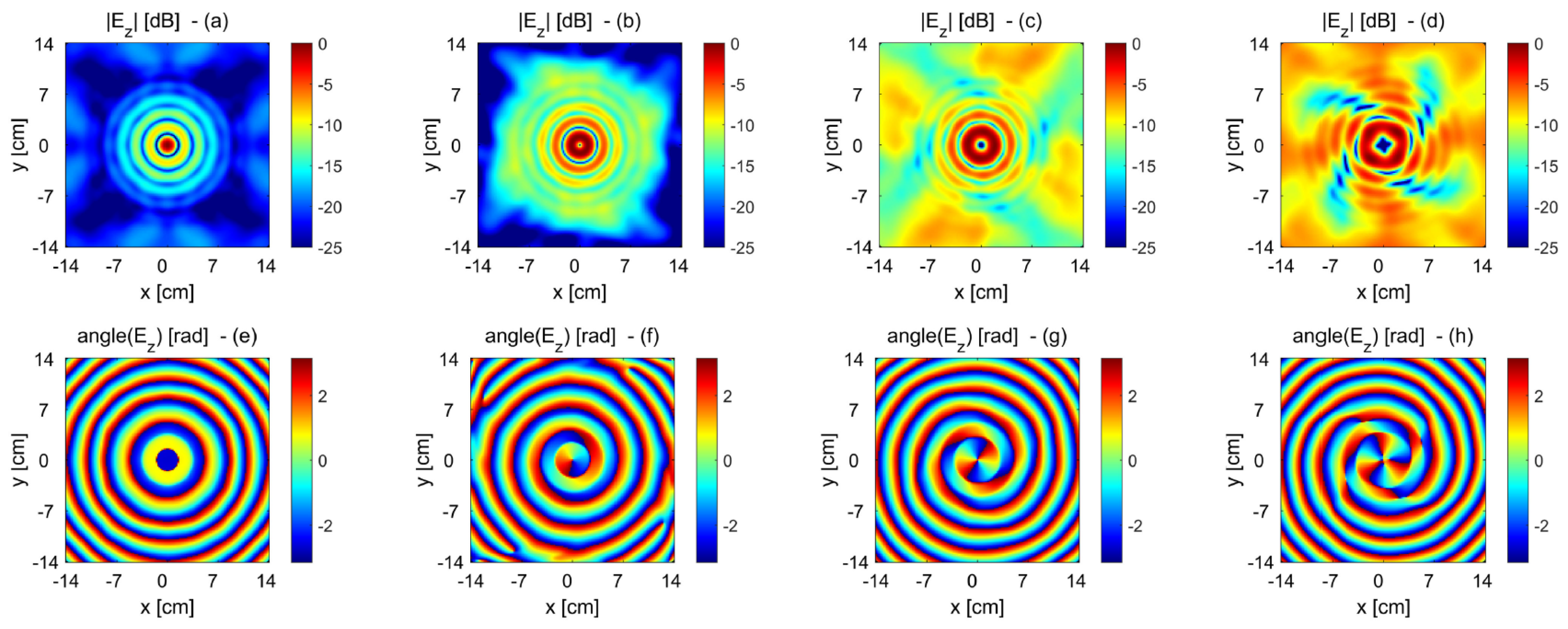
considering the component, for , the phase constant maintains a linear dependence with respect to azimuth angle , whereas the amplitude slope remains quasi-flat, with the only exception for , where some oscillations appear within the ±3 dB region with respect to the maximum. Finally, magnitude and phase distributions are presented for multiple values of the index ℓ in Figure 15.
The chosen array parameters have been proven capable to ensure a satisfactory feeding, with an average level of -15 dB for the generic scattering parameter and -10 dB for active scattering parameters. The overall design allows us to create a compact device with a satisfactory OAM purity up to nondiffractive limit represented by , with OAM order selection possible among , with little or no impact on the nondiffractive range for a selected frequency.
4. Conclusion
In this paper, several different 2-D planar antenna structures fed by phased arrays have been reviewed, emphasizing advanced radiative features achieved at limited complexity cost. The common property of the presented devices consists in the excitation of cylindrical leaky waves on the planar surface which constitutes the antenna aperture. The simplicity in providing an elevation scan, resulting from the frequency dispersion of relevant supported leaky-mode wavenumbers, substantially simplifies several critical design details, which otherwise would require significant additional efforts.
The review has been focused on two categories, Fabry–Perot Cavity Antennas and Bull’s-Eye Antennas, both capable of producing narrow pencil beams at broadside or conical scanned beams.
Array-fed Fabry-Perot Cavity antennas have been seen capable of achieving reconfigurable far-field polarization, or reconfigurable orbital-angular-momentum order, or 2-D beam scanning in elevation and azimuth.
Bull’s-Eye Antennas exhibit a richer modal spectrum, allowing negative radial wavenumbers, corresponding to cylindrical backward leaky-waves. This valuable characteristic has been shown to be useful for producing diffraction-resistant Bessel-like beams which, when excited by circular phased arrays, may exhibit a higher azimuthal order and thus carry nonzero orbital angular momentum.
Finally, when compared with traditional phased-array configurations, both the considered categories of leaky-wave antennas require a very reduced number of simple, inexpensive, broadly available primary radiators, whose reduced complexity substantially simplifies the design and realization of feeding networks.
References
- Hessel, A. General characteristics of traveling-wave antennas. In Antenna Theory, Part 2; Collin, R.E., Zucker, F.J., Eds.; McGraw-Hill: New York, 1969. [Google Scholar]
- Marcuvitz, N. On field representations in terms of leaky modes or eigenmodes. IRE Trans. Antennas Propag. 1956, 4, 192–194. [Google Scholar] [CrossRef]
- Goldstone, L.; Oliner, A. Leaky-wave antennas I: Rectangular Waveguides. IRE Trans. Antennas Propag. 1959, 7, 307–319. [Google Scholar] [CrossRef]
- Goldstone, L.; Oliner, A. Leaky-wave antennas II: Circular Waveguides. IRE Trans. Antennas Propag. 1961, 9, 280–290. [Google Scholar] [CrossRef]
- Balanis, C.A. Advanced Engineering Electromagnetics; 2012.
- Ip, A.; Jackson, D.R. Radiation from cylindrical leaky waves. IEEE Trans. Antennas Propag. 1990, 38, 482–488. [Google Scholar] [CrossRef]
- Felsen, L. Real spectra, complex spectra, compact spectra. JOSA A 1986, 3, 486–496. [Google Scholar] [CrossRef]
- Fuscaldo, W.; Jackson, D.R.; Galli, A. General formulas for the beam properties of 1-D bidirectional leaky-wave antennas. IEEE Trans. Antennas Propag. 2019, 67, 3597–3608. [Google Scholar] [CrossRef]
- Zhao, T.; Jackson, D.R.; Williams, J.T.; Oliner, A.A. General formulas for 2-D leaky-wave antennas. IEEE Trans. Antennas Propag. 2005, 53, 3525–3533. [Google Scholar] [CrossRef]
- Tamir, T.; Oliner, A.A. Guided complex waves, Part 1: Fields at an interface Fields at an interface. Proc. Inst. Electr. Eng. 1963, 110, 310. [Google Scholar] [CrossRef]
- Tamir, T.; Oliner, A.A. Guided complex waves, Part 2: Relation to radiation patterns. Proc. Inst. Electr. Eng. 1963, 110, 325. [Google Scholar] [CrossRef]
- Fuscaldo, W.; Burghignoli, P.; Galli, A. Genealogy of Leaky, Surface, and Plasmonic Modes in Partially Open Waveguides. Phys. Rev. Appl. 2022, 17, 034–038. [Google Scholar] [CrossRef]
- Fabry, C. Theorie et applications d’une nouvelle methods de spectroscopie intereferentielle. Ann. Chim. Ser. 7 1899, 16, 115–144. [Google Scholar]
- Trentini, G.V. Partially reflecting sheet arrays. IRE Trans. Antennas Propag. 1956, 4, 666–671. [Google Scholar] [CrossRef]
- Jackson, D.; Oliner, A.; Ip, A. Leaky-wave propagation and radiation for a narrow-beam multiple-layer dielectric structure. IEEE Trans. Antennas Propag. 1993, 41, 344–348. [Google Scholar] [CrossRef]
- Lovat, G.; Burghignoli, P.; Jackson, D.R. Fundamental properties and optimization of broadside radiation from uniform leaky-wave antennas. IEEE Trans. Antennas Propag. 2006, 54, 1442–1452. [Google Scholar] [CrossRef]
- Burghignoli, P.; Fuscaldo, W.; Galli, A. Fabry–Perot Cavity Antennas: The Leaky-Wave Perspective. IEEE Antennas Propag. Mag. 2021, 63, 116–145. [Google Scholar] [CrossRef]
- Burghignoli, P.; Fuscaldo, W.; Mancini, F.; Comite, D.; Baccarelli, P.; Galli, A. Twisted beams with variable OAM order and consistent beam angle via single uniform circular arrays. IEEE Access 2020, 8, 163006–163014. [Google Scholar] [CrossRef]
- Su, H.; Shen, X.; Su, G.; Li, L.; Ding, J.; Liu, F.; Zhan, P.; Liu, Y.; Wang, Z. Efficient generation of microwave plasmonic vortices via a single deep-subwavelength meta-particle. Laser Photon. Rev. 2018, 12, 1800010. [Google Scholar] [CrossRef]
- Yan, Y.; Xie, G.; Lavery, M.P.; Huang, H.; Ahmed, N.; Bao, C.; Ren, Y.; Cao, Y.; Li, L.; Zhao, Z.; et al. High-capacity millimetre-wave communications with orbital angular momentum multiplexing. Nat. Commun. 2014, 5, 4876. [Google Scholar] [CrossRef] [PubMed]
- Allen, L.; Beijersbergen, M.W.; Spreeuw, R.; Woerdman, J. Orbital angular momentum of light and the transformation of Laguerre-Gaussian laser modes. Phys. Rev. Appl. 1992, 45, 8185. [Google Scholar] [CrossRef]
- Lee, D.; Sasaki, H.; Fukumoto, H.; Yagi, Y.; Shimizu, T. An evaluation of orbital angular momentum multiplexing technology. Appl. Sci. 2019, 9, 1729. [Google Scholar] [CrossRef]
- Trichili, A.; Park, K.H.; Zghal, M.; Ooi, B.S.; Alouini, M.S. Communicating using spatial mode multiplexing: Potentials, challenges, and perspectives. IEEE Commun. Surv. Tutor. 2019, 21, 3175–3203. [Google Scholar] [CrossRef]
- Yuan, T.; Wang, H.; Qin, Y.; Cheng, Y. Electromagnetic vortex imaging using uniform concentric circular arrays. IEEE Antennas and Wireless Propag. Lett. 2015, 15, 1024–1027. [Google Scholar] [CrossRef]
- Luukkonen, O.; Simovski, C.; Granet, G.; Goussetis, G.; Lioubtchenko, D.; Raisanen, A.V.; Tretyakov, S.A. Simple and accurate analytical model of planar grids and high-impedance surfaces comprising metal strips or patches. IEEE Trans. Antennas Propag. 2008, 56, 1624–1632. [Google Scholar] [CrossRef]
- Burghignoli, P.; Fuscaldo, W.; Comite, D.; Baccarelli, P.; Galli, A. Higher-Order Cylindrical Leaky Waves–Part I: Canonical sources and radiation formulas. IEEE Trans. Antennas Propag. 2019, 67, 6735–6747. [Google Scholar] [CrossRef]
- Burghignoli, P.; Comite, D.; Fuscaldo, W.; Baccarelli, P.; Galli, A. Higher-Order Cylindrical Leaky Waves–Part II: Circular Array Design and Validations. IEEE Trans. Antennas Propag. 2019, 67, 6748–6760. [Google Scholar] [CrossRef]
- Kajiwara, A. Line-of-sight indoor radio communication using circular polarized waves. IEEE Trans. Veh. Technol. 1995, 44, 487–493. [Google Scholar] [CrossRef]
- Comite, D.; Baccarelli, P.; Burghignoli, P.; Galli, A. Omnidirectional 2-D leaky-wave antennas with reconfigurable polarization. IEEE Antennas and Wireless Propag. Lett. 2017, 16, 2354–2357. [Google Scholar] [CrossRef]
- Fuscaldo, W.; Galli, A.; Jackson, D.R. Optimization of 1-D unidirectional leaky-wave antennas based on partially reflecting surfaces. IEEE Trans. Antennas Propag. 2022, 70, 7853–7868. [Google Scholar] [CrossRef]
- Mailloux, R.J. Phased array antenna handbook; Artech House, 2017.
- Borselli, L.; Di Nallo, C.; Galli, A.; Maci, S. Arrays with widely-spaced high-gain planar elements. Proc. IEEE Antennas Propag. Soc. Int. Symp. 1998 Digest. Antennas: Gateways to the Global Network. Held in conjunction with: USNC/URSI Nat. Radio Sci. Meeting (Cat. No. 98CH36). IEEE, 1998, Vol. 2, pp. 1142–1145.
- Gardelli, R.; Albani, M.; Capolino, F. Array thinning by using antennas in a Fabry–Perot cavity for gain enhancement. IEEE Trans. Antennas and Propag. 2006, 54, 1979–1990. [Google Scholar] [CrossRef]
- Scattone, F.; Ettorre, M.; Fuchs, B.; Sauleau, R.; Fonseca, N.J. Synthesis procedure for thinned leaky-wave-based arrays with reduced number of elements. IEEE Trans. Antennas Propag. 2015, 64, 582–590. [Google Scholar] [CrossRef]
- Costa, F.; Bianchi, D.; Monorchio, A.; Manara, G. Analytical design of extremely high-gain Fabry-Perot/leaky antennas by using multiple feeds. Proc. Int. Conf. Electromagn. Adv. Appl. (ICEAA), 2017. IEEE, 2017, pp. 1673–1675.
- Shahzadi, I.; Comite, D.; Kuznetcov, M.V.; Podilchak, S.K. Compact Dual-Polarized Fabry-Perot Leaky-Wave Antenna for Full-Duplex Broadband Applications. IEEE Antennas and Wireless Propag. Lett. 2024. [Google Scholar] [CrossRef]
- Comite, D.; Burghignoli, P.; Baccarelli, P.; Galli, A. 2-D beam scanning with cylindrical-leaky-wave-enhanced phased arrays. IEEE Trans. Antennas and Propag. 2019, 67, 3797–3808. [Google Scholar] [CrossRef]
- Comite, D.; Podilchak, S.K.; Kuznetcov, M.; Buendía, V.G.G.; Burghignoli, P.; Baccarelli, P.; Galli, A. Wideband array-fed Fabry-Perot cavity antenna for 2-D beam steering. IEEE Trans. Antennas and Propag. 2020, 69, 784–794. [Google Scholar] [CrossRef]
- Baccarelli, P.; Burghignoli, P.; Lovat, G.; Paulotto, S. A novel printed leaky-wave’Bull’s-Eye’antenna with suppressed surface-wave excitation. Proc. IEEE Antennas Propag. Soc. Symp., 2004. IEEE, 2004, Vol. 1, pp. 1078–1081.
- Encinar, J.A. Mode-matching and point-matching techniques applied to the analysis of metal-strip-loaded dielectric antennas. IEEE Trans. Antennas Propag. 1990, 38, 1405–1412. [Google Scholar] [CrossRef]
- Guglielmi, M.; Jackson, D. Broadside radiation from periodic leaky-wave antennas. IEEE Trans. Antennas Propag. 1993, 41, 31–37. [Google Scholar] [CrossRef]
- Burghignoli, P.; Baccarelli, P.; Frezza, F.; Galli, A.; Lampariello, P.; Oliner, A. Low-frequency dispersion features of a new complex mode for a periodic strip grating on a grounded dielectric slab. IEEE Trans. Microwave Theory Tech. 2002, 49, 2197–2205. [Google Scholar] [CrossRef]
- Albani, M.; Pavone, S.C.; Casaletti, M.; Ettorre, M. Generation of non-diffractive Bessel beams by inward cylindrical traveling wave aperture distributions. Opt. Express 2014, 22, 18354–18364. [Google Scholar] [CrossRef] [PubMed]
- Cai, B.G.; Li, Y.B.; Jiang, W.X.; Cheng, Q.; Cui, T.J. Generation of spatial Bessel beams using holographic metasurface. Opt. Express 2015, 23, 7593–7601. [Google Scholar] [CrossRef] [PubMed]
- Ettorre, M.; Grbic, A. Generation of propagating Bessel beams using leaky-wave modes. IEEE Trans. Antennas Propag. 2012, 60, 3605–3613. [Google Scholar] [CrossRef]
- Fuscaldo, W.; Comite, D.; Boesso, A.; Baccarelli, P.; Burghignoli, P.; Galli, A. Focusing Leaky Waves: A Class of Electromagnetic Localized Waves with Complex Spectra. Phys. Rev. Appl. 4005, 9, 9. [Google Scholar] [CrossRef]
- Liu, H.; Xue, H.; Liu, Y.; Feng, Q.; Li, L. Generation of high-order Bessel orbital angular momentum vortex beam using a single-layer reflective metasurface. IEEE Access 2020, 8, 126504–126510. [Google Scholar] [CrossRef]
- Shen, Y.; Yang, J.; Meng, H.; Dou, W.; Hu, S. Generating millimeter-wave Bessel beam with orbital angular momentum using reflective-type metasurface inherently integrated with source. Appl. Phys. Lett. 2018, 112. [Google Scholar] [CrossRef]
- Wu, G.B.; Chan, K.F.; Chan, C.H. 3-D printed terahertz lens to generate higher order Bessel beams carrying OAM. IEEE Trans. Antennas Propag. 2020, 69, 3399–3408. [Google Scholar] [CrossRef]
- Xu, X.; Mazzinghi, A.; Freni, A.; Hirokawa, J. Simultaneous generation of three OAM modes by using a RLSA fed by a waveguide circuit for 60 GHz-band radiative near-field region OAM multiplexing. IEEE Trans. Antennas Propag. 2020, 69, 1249–1259. [Google Scholar] [CrossRef]
- Comite, D.; Fuscaldo, W.; Merola, G.; Burghignoli, P.; Baccarelli, P.; Galli, A. Twisted Bessel beams via bull-eye antennas excited by a single uniform circular array. IEEE Antennas and Wireless Propag. Lett. 2021, 20, 663–667. [Google Scholar] [CrossRef]
Figure 1.
Pictorial representation of a Fabry-Perot Cavity antenna (FPCA), with the relevant reference system.
Figure 1.
Pictorial representation of a Fabry-Perot Cavity antenna (FPCA), with the relevant reference system.
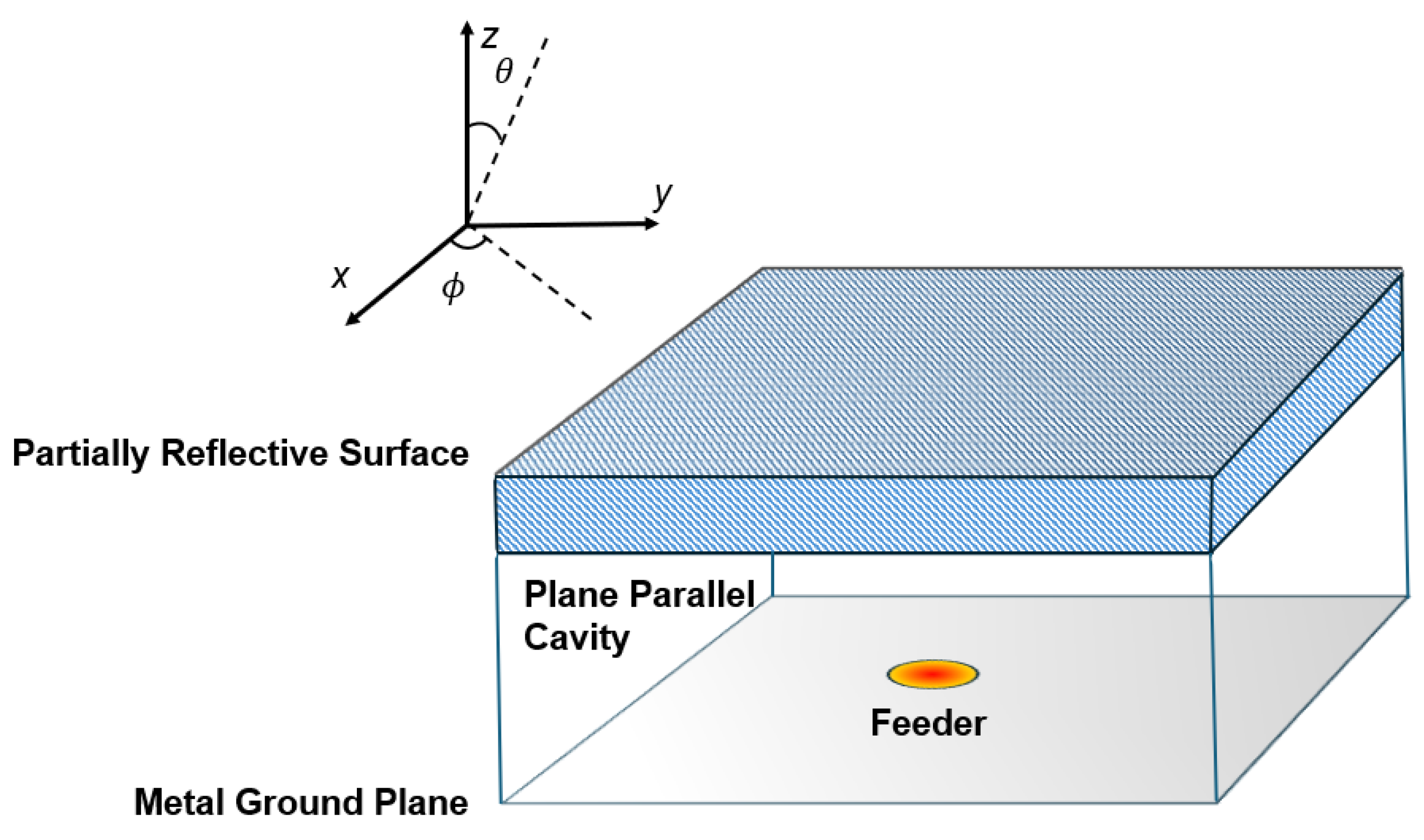
Figure 2.
Dispersion diagram for the dominant leaky-mode supported by an FPCA. Two different curves both for phase and attenuation constants correspond to two different low permittivity dielectrics, obtained respectively with a single layer and through a multilayer, reproduced from [18].
Figure 2.
Dispersion diagram for the dominant leaky-mode supported by an FPCA. Two different curves both for phase and attenuation constants correspond to two different low permittivity dielectrics, obtained respectively with a single layer and through a multilayer, reproduced from [18].
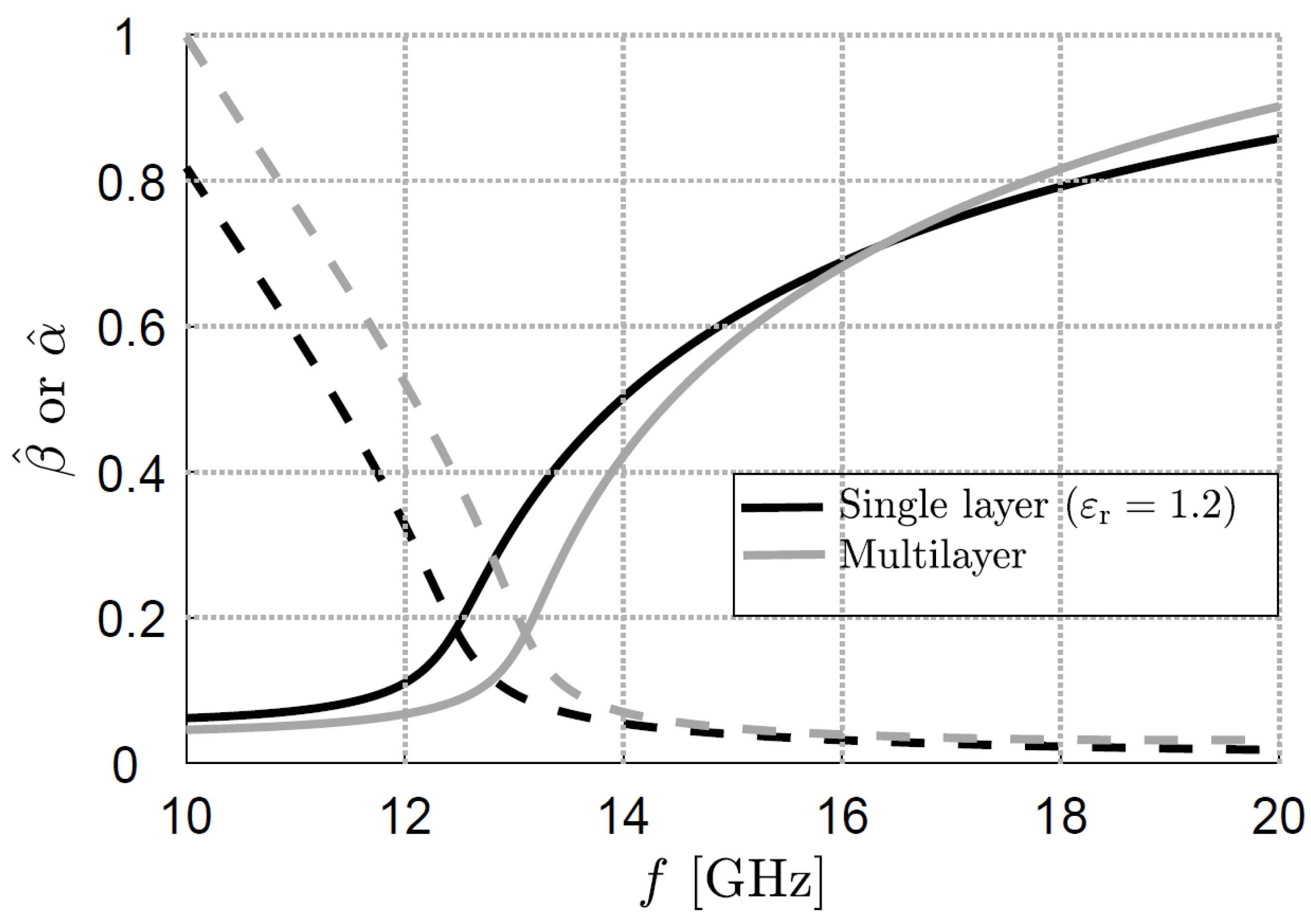
Figure 3.
Normalized radiation pattern for the ideally-infinite FPCA extension, at a frequency of 18 GHz, for an elevation angle of , with the filling low-permittivity dielectric obtained with a single layer; further details and effects due to FPCA truncation are available in [18].
Figure 3.
Normalized radiation pattern for the ideally-infinite FPCA extension, at a frequency of 18 GHz, for an elevation angle of , with the filling low-permittivity dielectric obtained with a single layer; further details and effects due to FPCA truncation are available in [18].
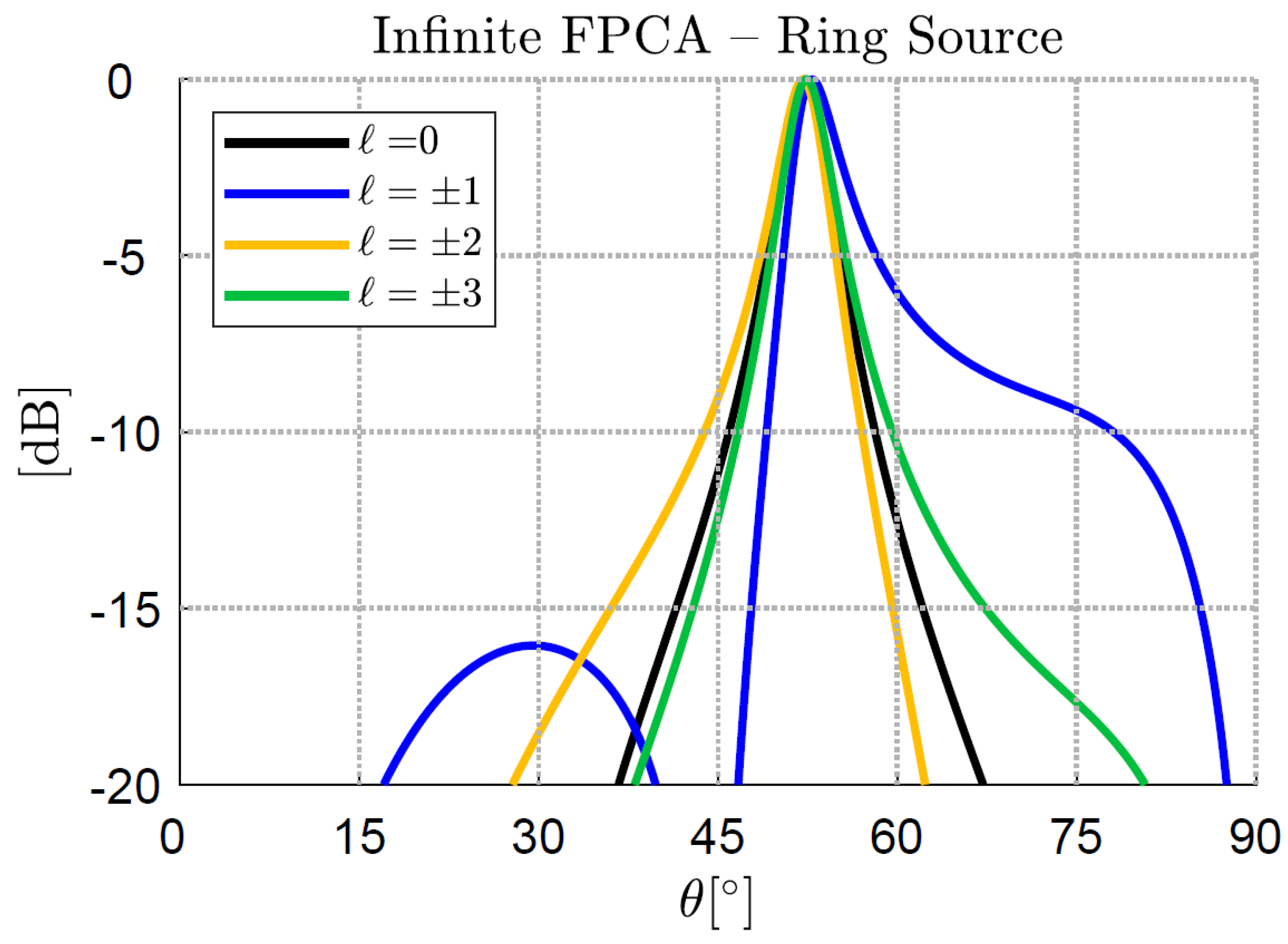
Figure 4.
Reflection and transmission coefficients of the optimized FPCA feeding network. Due to circular symmetry of the feeding array, a limited number of scattering parameters has been simulated and reported in [18].
Figure 4.
Reflection and transmission coefficients of the optimized FPCA feeding network. Due to circular symmetry of the feeding array, a limited number of scattering parameters has been simulated and reported in [18].
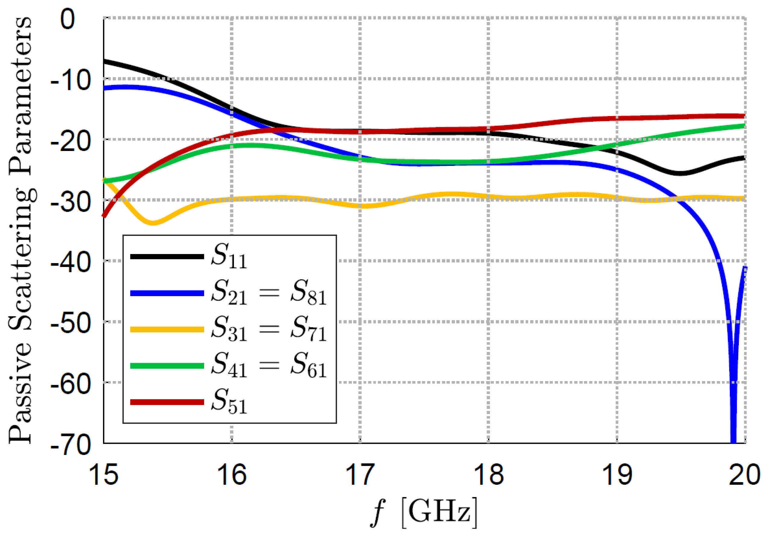
Figure 5.
Frequency sweep and related beam scanning for produced and modes, over a frequency span between 12 and 19 GHz. Only a slight deviation from the equalization condition is observed around 12 and 19 GHz. Reproduced from [29].
Figure 5.
Frequency sweep and related beam scanning for produced and modes, over a frequency span between 12 and 19 GHz. Only a slight deviation from the equalization condition is observed around 12 and 19 GHz. Reproduced from [29].
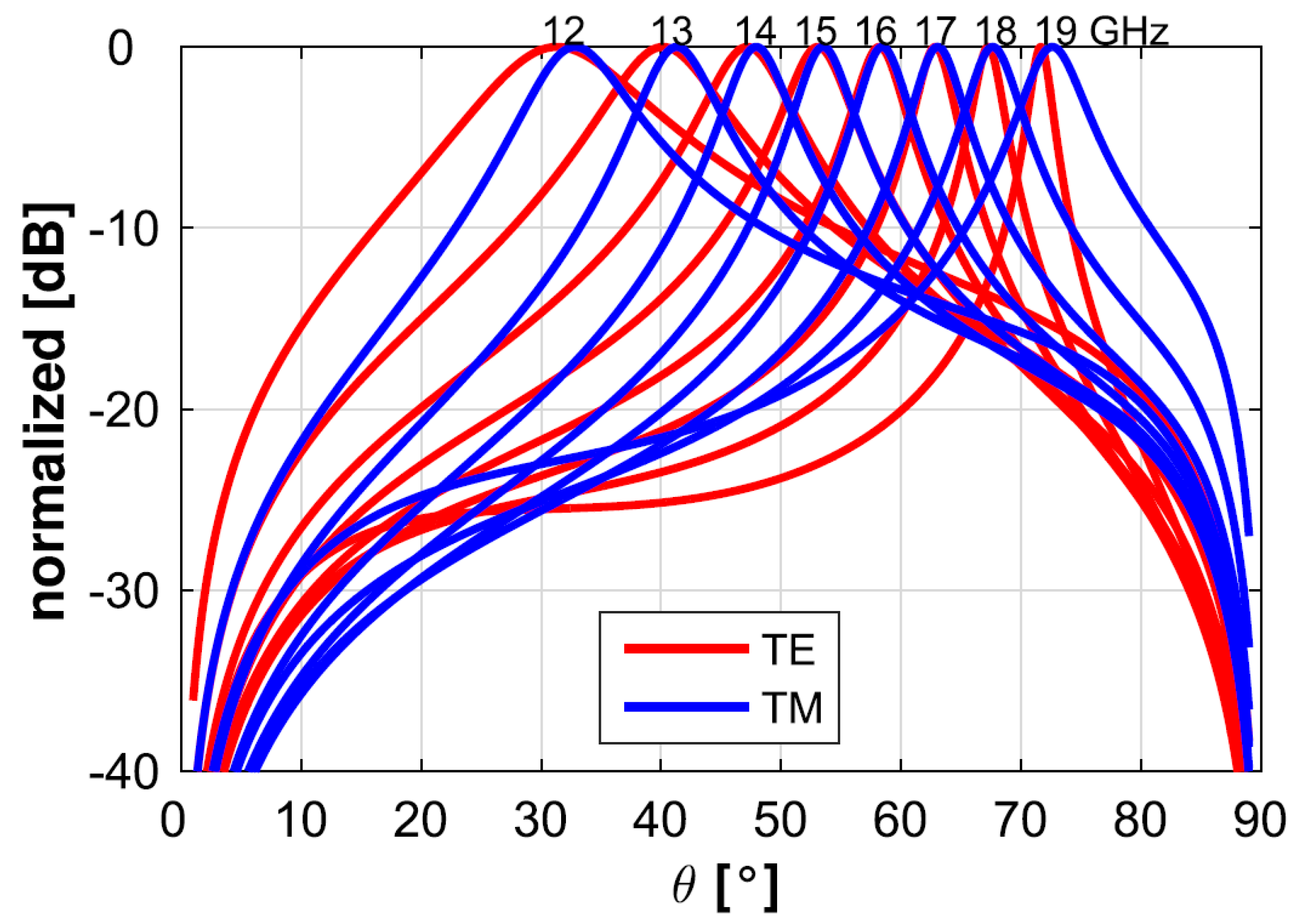
Figure 6.
RHCP (solid lines) component frequency-scanning process in the elevation plane. As expected, the cross-polarized component (dotted lines) is negligible in a wide range of frequencies. Reproduced from [29].
Figure 6.
RHCP (solid lines) component frequency-scanning process in the elevation plane. As expected, the cross-polarized component (dotted lines) is negligible in a wide range of frequencies. Reproduced from [29].
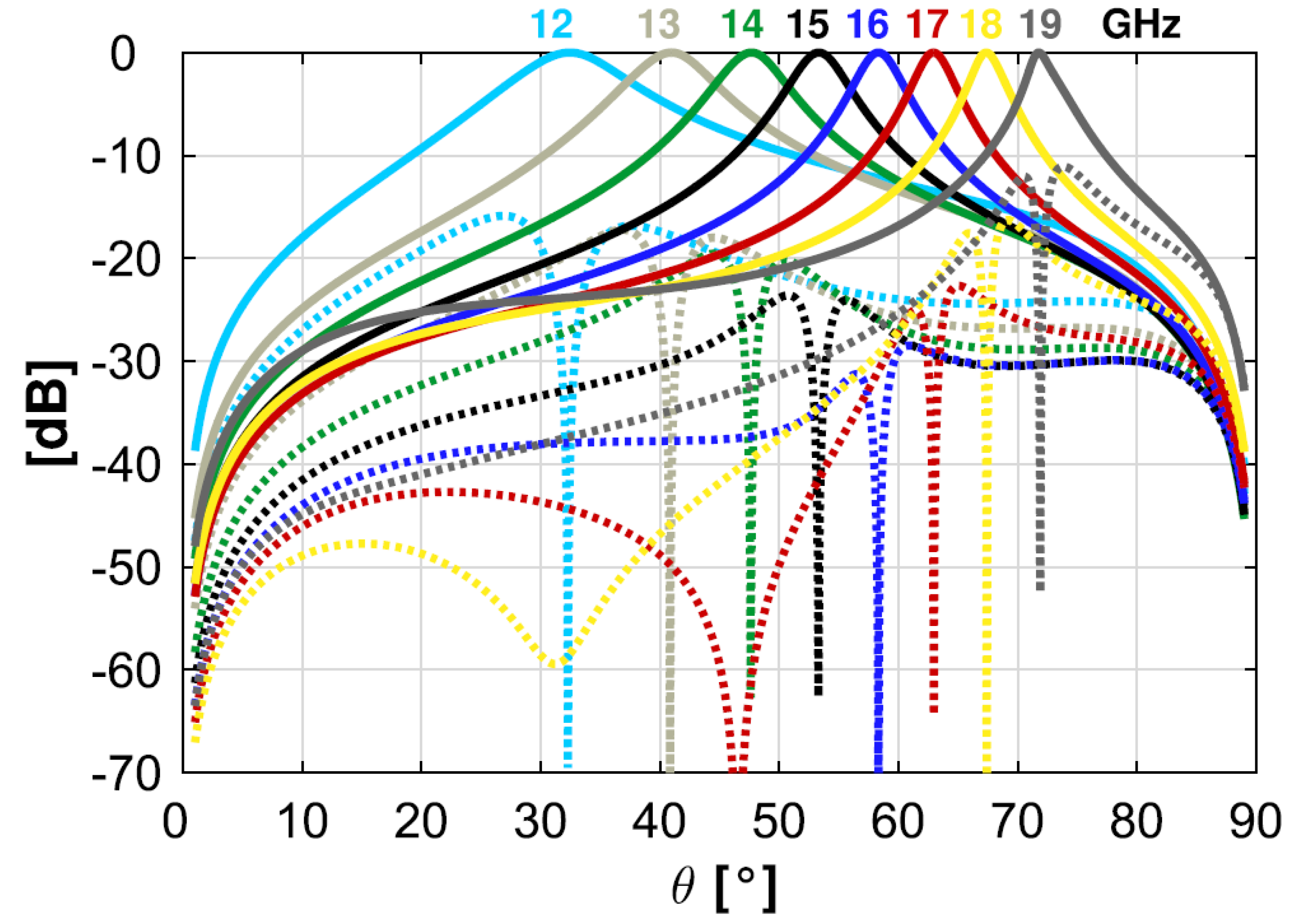
Figure 7.
Dispersion of radial phase (red lines) and attenuation constants (blue lines) for multiple values of distance s between metallic patches composing the PRS. Higher values of s induce higher attenuation while weakly affecting the phase constant. Reproduced from [37].
Figure 7.
Dispersion of radial phase (red lines) and attenuation constants (blue lines) for multiple values of distance s between metallic patches composing the PRS. Higher values of s induce higher attenuation while weakly affecting the phase constant. Reproduced from [37].
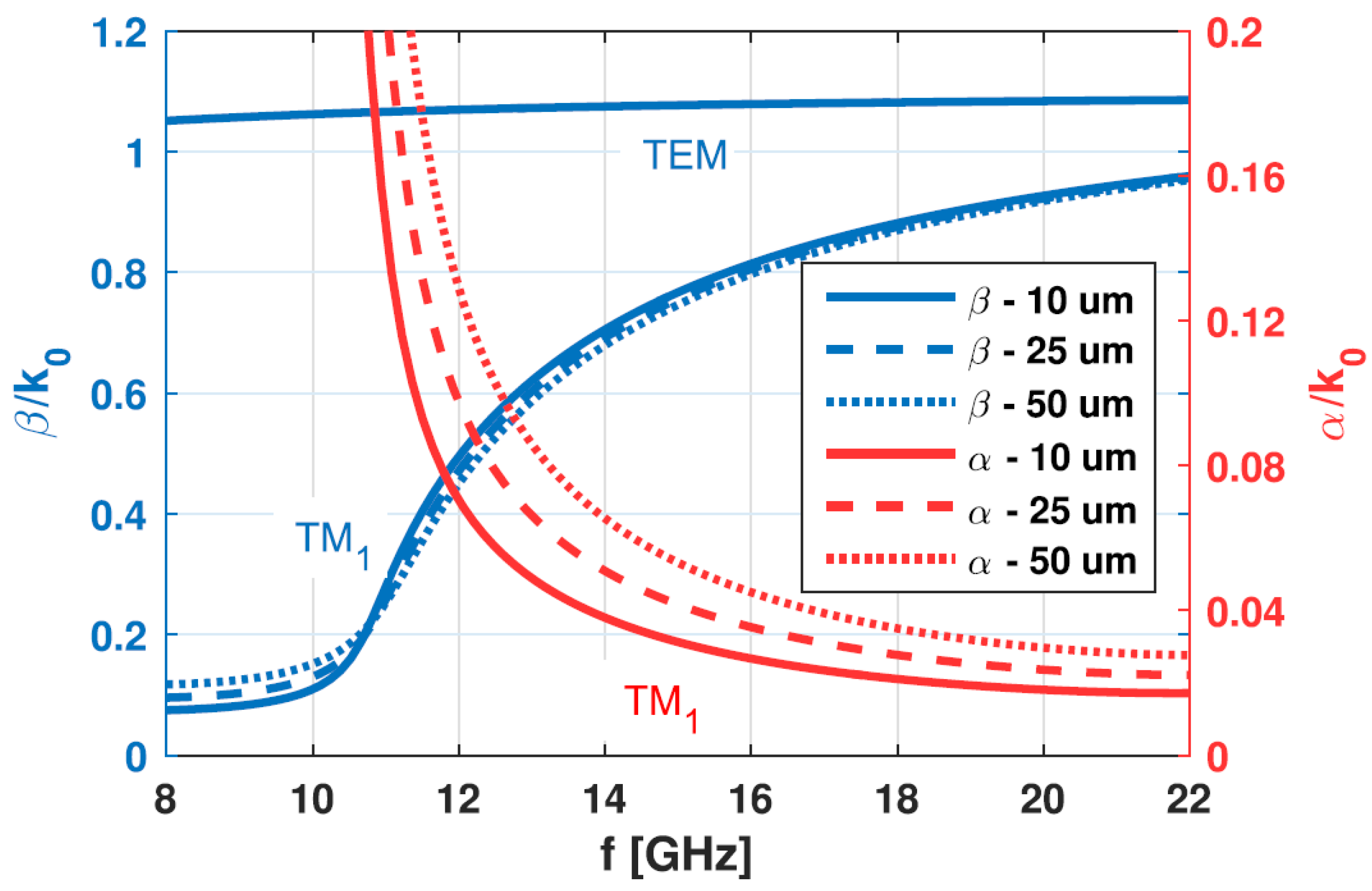
Figure 8.
Cylindrical leaky-wave model, truncated cylindrical leaky-wave model and reciprocity-obtained elevation pattern (TEN) at 16 GHz. (a) s=50 m, (b) s=10 m, (c) as in (b) but radiating 99% of input power. Reproduced from [37].
Figure 8.
Cylindrical leaky-wave model, truncated cylindrical leaky-wave model and reciprocity-obtained elevation pattern (TEN) at 16 GHz. (a) s=50 m, (b) s=10 m, (c) as in (b) but radiating 99% of input power. Reproduced from [37].
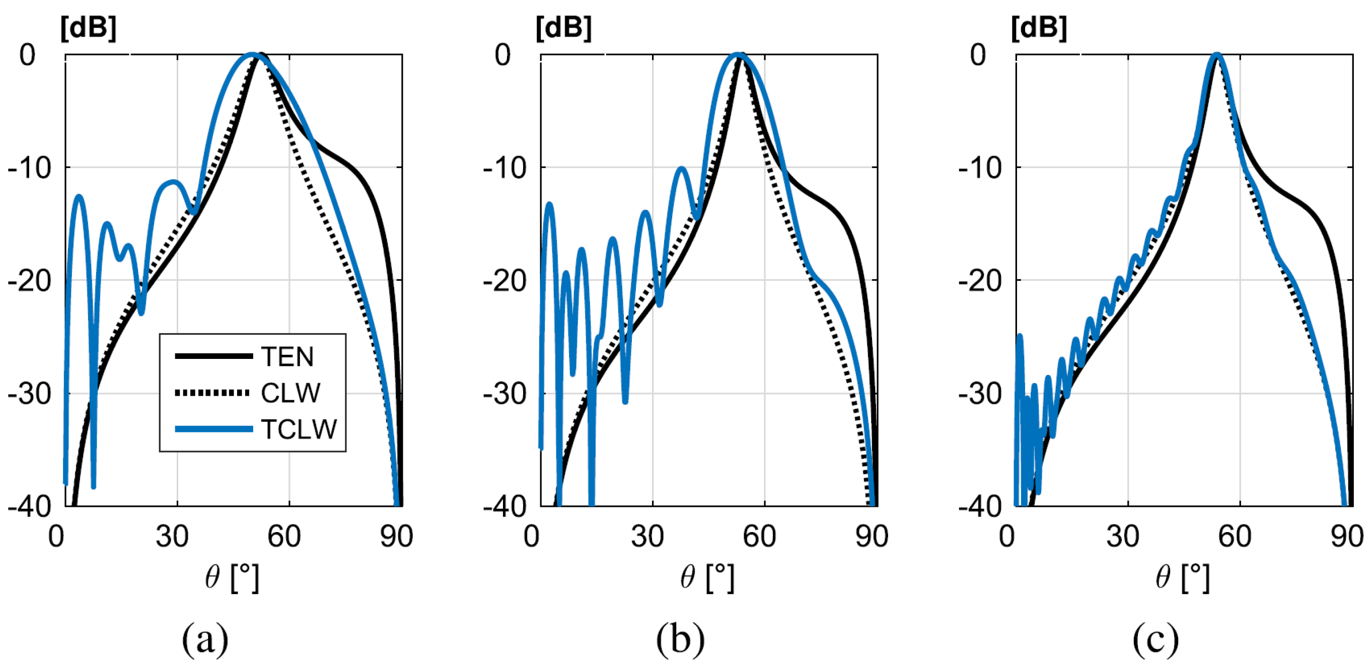
Figure 9.
Directivity colormaps in the -plane for an array-fed FPCA, for multiple frequency values and two main beam azimuth planes. (a) GHz, , (b) GHz, , (c) GHz, , (d) GHz, , (e) GHz, , (f) GHz, . Reproduced from [37].
Figure 9.
Directivity colormaps in the -plane for an array-fed FPCA, for multiple frequency values and two main beam azimuth planes. (a) GHz, , (b) GHz, , (c) GHz, , (d) GHz, , (e) GHz, , (f) GHz, . Reproduced from [37].
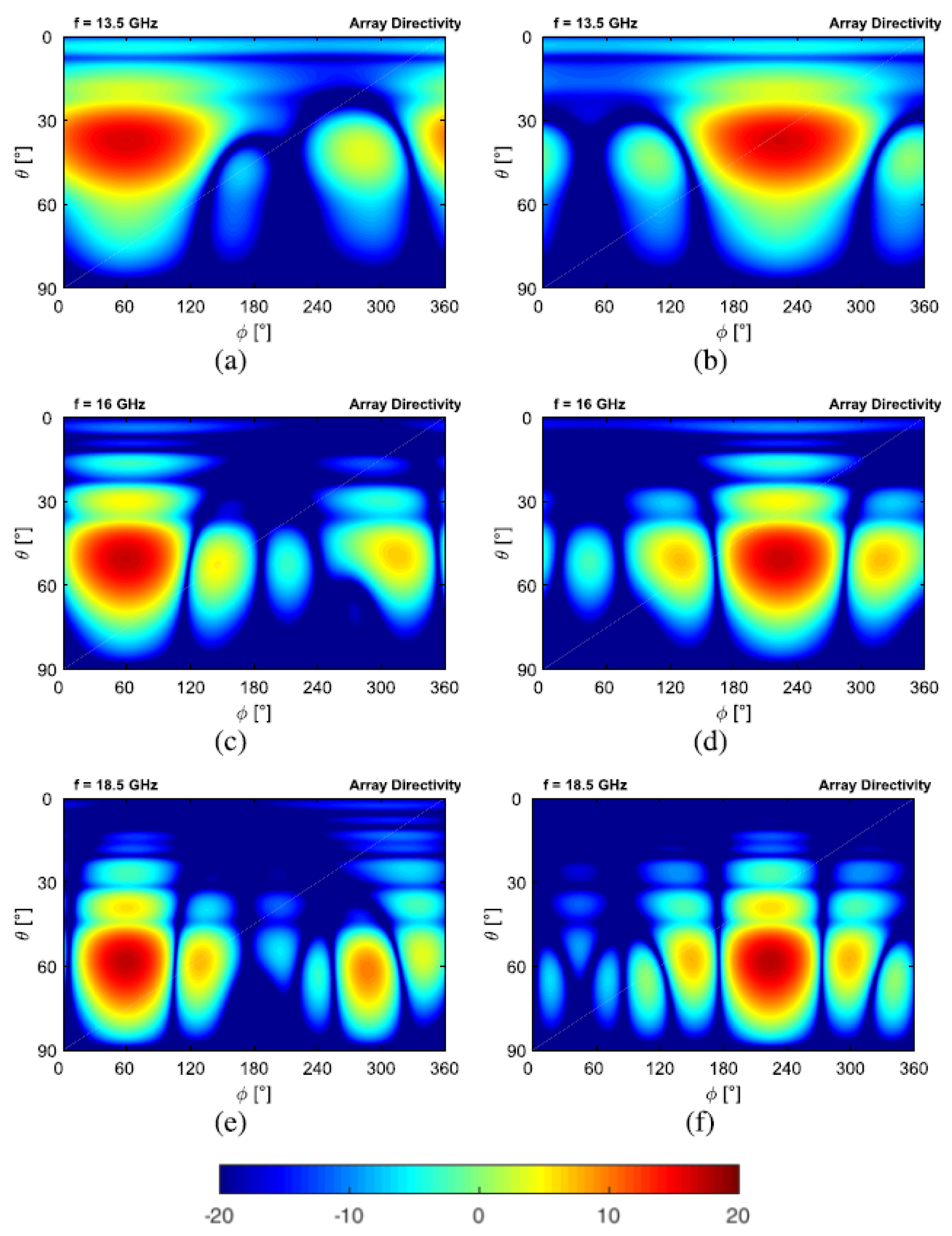
Figure 10.
Input reflection coefficients for a 3× 3 square planar VEDs array inside an FPCA. The horizontal dashed black line corresponds to the -10 dB threshold. Reproduced from [37].
Figure 10.
Input reflection coefficients for a 3× 3 square planar VEDs array inside an FPCA. The horizontal dashed black line corresponds to the -10 dB threshold. Reproduced from [37].
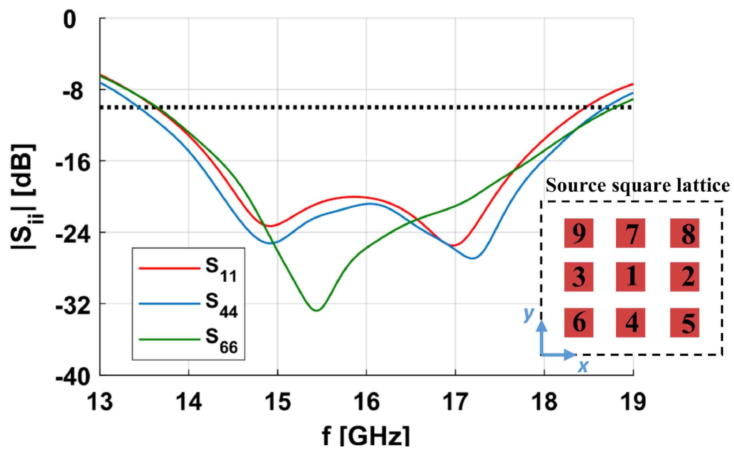
Figure 11.
Simulated values for reflection coefficient magnitude, considering different numbers of via-rings. Inserting more concentric rings the reflection coefficient dip shifts to higher frequencies. Reproduced from [38].
Figure 11.
Simulated values for reflection coefficient magnitude, considering different numbers of via-rings. Inserting more concentric rings the reflection coefficient dip shifts to higher frequencies. Reproduced from [38].
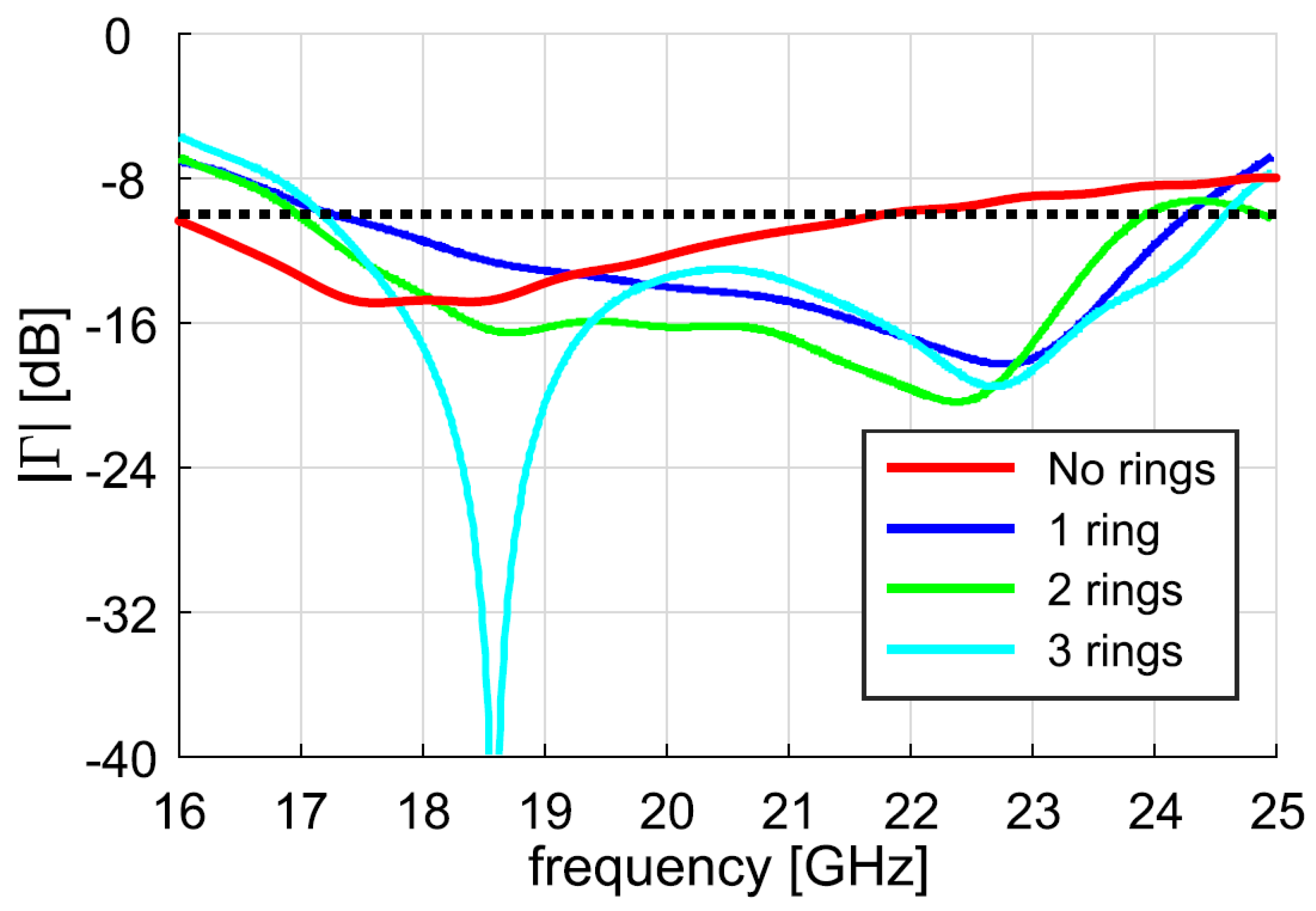
Figure 12.
FPCA fed by a circular array with N elements: Simulated maximum directivity for (green dotted line) and main sidelobe level at 20 GHz for with (solid lines). Reproduced from [38].
Figure 12.
FPCA fed by a circular array with N elements: Simulated maximum directivity for (green dotted line) and main sidelobe level at 20 GHz for with (solid lines). Reproduced from [38].
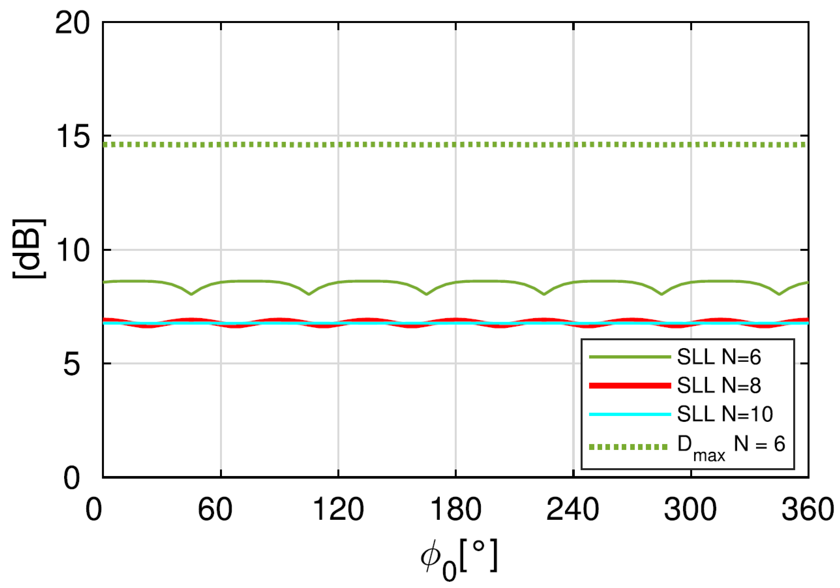
Figure 13.
Pictorial representation of a Bull’s Eye Antenna, constituted by an arrangement of concentric microstrip rings on top of a grounded dielectric slab.
Figure 13.
Pictorial representation of a Bull’s Eye Antenna, constituted by an arrangement of concentric microstrip rings on top of a grounded dielectric slab.
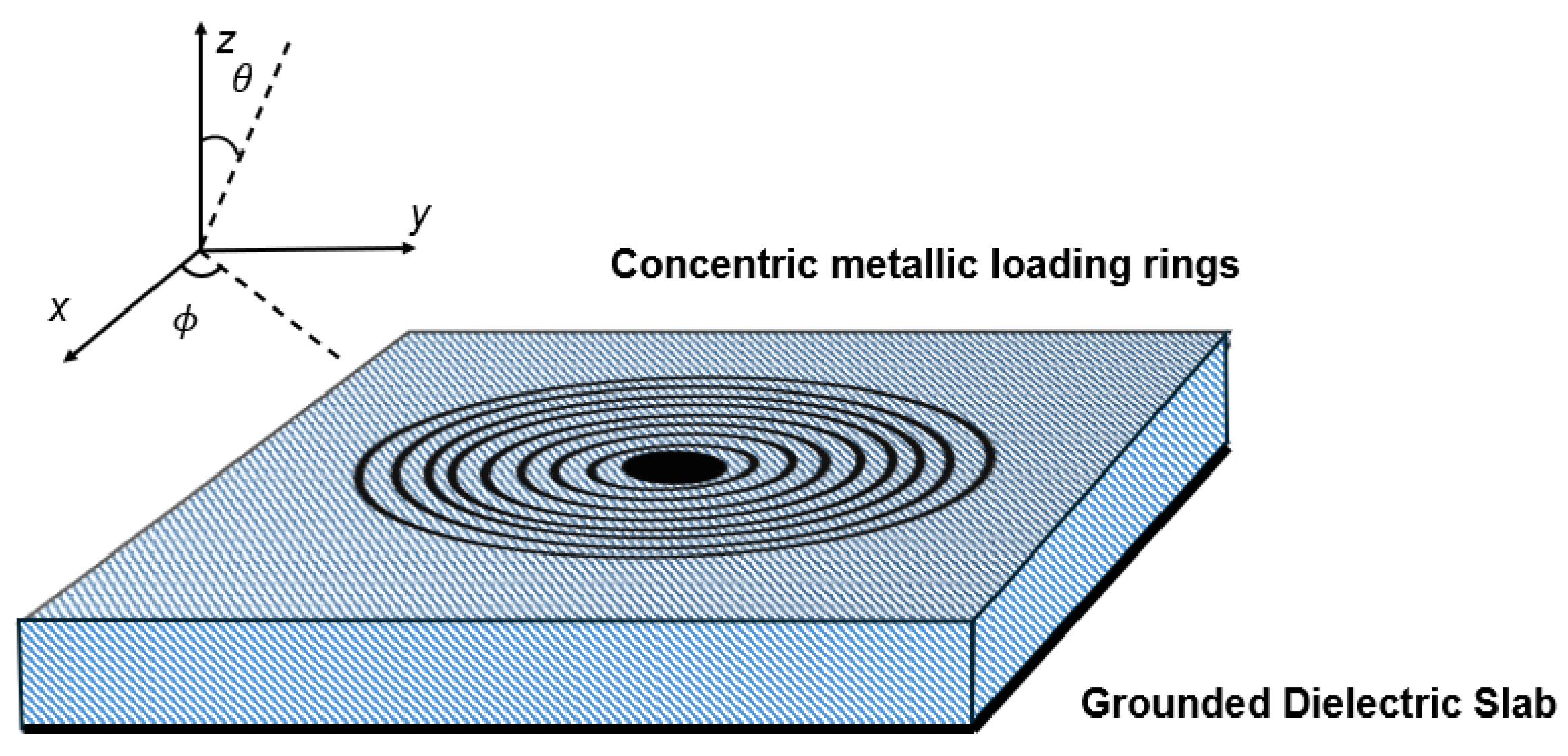
Figure 14.
Electric field along the cone of maximum amplitude radiated by a BEA fed by a circular phased array. (a) Magnitude in dBV/m and (b) phase in degrees. Reproduced from [51].
Figure 14.
Electric field along the cone of maximum amplitude radiated by a BEA fed by a circular phased array. (a) Magnitude in dBV/m and (b) phase in degrees. Reproduced from [51].
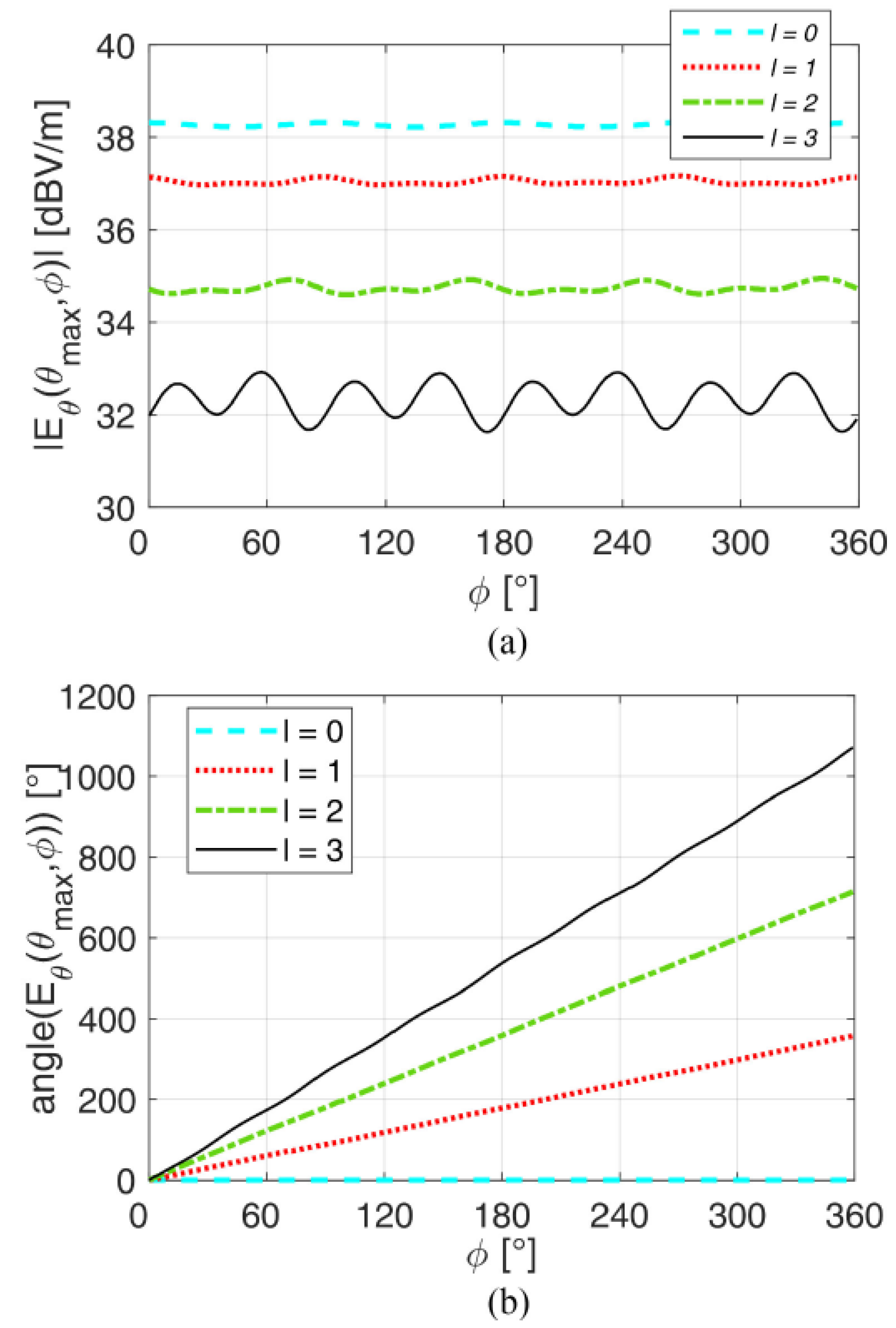
Figure 15.
BEA fed by a circular array for the generation of twisted Bessel beams: component magnitude and phase distributions over a transverse plane for different azimuthal orders at a frequency of 18 GHz, with . (a)-(d) Magnitude (dB). (e)-(h) Phase (rad). Reproduced from [51].
Figure 15.
BEA fed by a circular array for the generation of twisted Bessel beams: component magnitude and phase distributions over a transverse plane for different azimuthal orders at a frequency of 18 GHz, with . (a)-(d) Magnitude (dB). (e)-(h) Phase (rad). Reproduced from [51].
Disclaimer/Publisher’s Note: The statements, opinions and data contained in all publications are solely those of the individual author(s) and contributor(s) and not of MDPI and/or the editor(s). MDPI and/or the editor(s) disclaim responsibility for any injury to people or property resulting from any ideas, methods, instructions or products referred to in the content. |
© 2024 by the authors. Licensee MDPI, Basel, Switzerland. This article is an open access article distributed under the terms and conditions of the Creative Commons Attribution (CC BY) license (https://creativecommons.org/licenses/by/4.0/).
Copyright: This open access article is published under a Creative Commons CC BY 4.0 license, which permit the free download, distribution, and reuse, provided that the author and preprint are cited in any reuse.


