

Submitted:
19 June 2024
Posted:
20 June 2024
You are already at the latest version
Abstract
Three-phase induction motors play a key role in industrial operations. However, their failure can result in serious operational problems. This study focuses on the early identification of faults through accurate diagnosis and classification of faults in three-phase induction motors, using artificial intelligence techniques, by analyzing current, temperature, and vibration signals. Experiments were conducted on a test bench, simulating real operating conditions, including stator phase unbalance, bearing damage and shaft unbalance. To classify the faults, an Auto-Regressive Neural Network with Exogenous Inputs (NARX) was developed. The parameters of this network were determined through a process of selecting the best network, using the scanning method with multiple training and validation iterations, with the introduction of new data. The results of these tests showed that the network had excellent generalization in all the situations evaluated, achieving the following accuracy rates: Motor without fault = 94.2%, Unbalance fault = 95%, Bearings with fault =98% and Stator with fault = 95%.
Keywords:
artificial intelligence
; failure classification
; induction Motor
; artificial neural network
1. Introduction
Three-phase induction motors (TIMs) are widely used as the driving force in various industrial applications, ranging from clean environments, such as in the food industry, to more challenging or aggressive environments in heavy installations, such as the petrochemical and metal processing industries. They are preferred due to several advantageous characteristics, including low cost, robustness, high reliability, and constructive simplicity. Many studies focus on improving the design, dynamic performance, and these machines’ efficiency [1]. Three-phase induction motors are electromechanical energy converters that transform the electrical input power from the power supply into the mechanical output power delivered to the load, considering the losses inherent in the process they are very efficient. In Brazil, industry demands 31.6% of the domestic electricity supply, and electric motors consume 68% of this energy in the industrial sector, highlighting the significant potential for energy savings. [2].
Motors are subject to unavoidable stresses in practice. Environmental, thermal, mechanical, magnetic, and electrical variations can cause certain faults in motors. These faults, if not detected and eliminated in time, can lead to an unexpected breakdown and stoppage of the motor and, consequently, a reduction in the industry’s efficiency and possible damage to equipment or people nearby [3].
Fault diagnosis can be carried out using traditional non-invasive techniques. These strategies generally involve analyzing parameters such as vibration, voltage, current, torque, and speed. [4].
As the installation of several backup motor units is not economical, the monitoring of induction machines is essential to ensure safe operation and maintain product quality. Monitoring, detection, classification, and diagnosis are crucial to keeping the equipment in good operating condition. There are invasive and non-invasive techniques for identifying machine faults, with non-invasive techniques generally being preferred. Artificial intelligence (AI) systems have been proposed for the non-invasive detection of machine faults. [5].
Fault diagnosis methods using computational intelligence, through techniques based on Artificial Neural Networks (ANNs), Fuzzy Inference Systems (FISs), and Genetic Algorithms (GAs), have shown promising results in detecting and identifying faults in three-phase induction motors.
The purpose of this work is to use artificial intelligence techniques to diagnose and classify faults related to shaft unbalance and bearing damage in three-phase induction motors. This will be done by monitoring current, vibration, and temperature signals. The main aim is to achieve superior accuracy in diagnosing these mechanical faults, harnessing the power of artificial intelligence for data analysis and pattern identification, which can result in more assertive and effective interventions in preventive and corrective maintenance of the equipment.
This article is organized as follows. Section 1 presents the introduction. Section 2 presents the preliminaries. Section 3 presents the theoretical background. Section 4 describes the materials and methods used. Section 5 presents the results obtained. Section 6 presents the discussions, while Section 7 concludes this article.
2. Preliminaries
Monitoring faults in three-phase induction motors has aroused the interest of many researchers, resulting in a growing number of papers on the subject. This section presents some of these studies.
In [6], observing the low dynamic processing capacity as the main limitation of modeling methods based on feed-forward neural networks for detecting turn faults in the stator winding of an induction motor, they presented a proposal to solve the problem by implementing a diagonal recurrent neural network based on an online turn fault detection approach. Two diagonal recurrent neural networks were used, one to estimate the severity of the fault and the other to determine the exact number of times it occurs. To make the network more accurate, an adaptive dynamic backpropagation algorithm was used. The results showed that the diagnostic model based on a diagonal recurrent neural network accurately determines the shorted turns, and is more effective than the diagnostic model based on a direct neural network.
In [7], they proposed a support vector machine algorithm based on artificial immunity for diagnosing faults in induction motors. Stator and rotor faults in an induction motor were detected using three-phase motor currents. Healthy and faulty motor conditions were classified in combined phase space using an immunity-based SVM algorithm. The optimal SVM parameters are obtained using a clonal selection algorithm. Motor currents were taken in a real experimental setup, and successful results were obtained.
In [8], they presented an approach to the problem of fault detection and isolation of three-phase induction motors using recurrent neural networks and dynamic Bayesian modeling. The idea was to create a neural model to emulate the system’s normal behavior and additional models to emulate various fault conditions. The neural models are placed in parallel with the system to be monitored, and fault detection is achieved by comparing the outputs of the neural models with the actual outputs of the system. The neural network was trained using the stochastic simultaneous perturbation approximation (SPSA). Fault classification was based on a simple threshold test of the residuals formed by subtracting each neural model output from the corresponding real system output. A hybrid system that used data collected by vibration and current sensors for the early and efficient detection of incipient faults in three-phase induction motors. The system employed advanced vibration and current analysis techniques, including multiresolution analysis with wavelet, Fourier transform, and fuzzy logic for fault classification.
An approach for monitoring the operating conditions of three-phase induction motors based on extracting the characteristics of a vibration signal obtained with a MEMS accelerometer. The data is extracted from the decomposition of the vibration signal by the Haar transform and through the fractal dimension, it is used to train an ELM Neural Network. In [9], they presented strategies for diagnosing and predicting faults and failures in induction motors as an alternative tool to traditional models for detecting short-circuit faults between stator turns, rotor bar breakage, and bearings under normal operating conditions using Artificial Neural Networks with a radial basis function. The current signals of a three-phase induction motor subjected to various fault conditions were treated and processed using synchronous axis transforms. The signals were classified using the RBF network, indicating the samples referring to the signals without faults and with the 3 types of faults. It was found that the network presented 1.33% error for loads of 1Nm, 2Nm, and 3Nm and zero error for loads of 4Nm and 5Nm. The experimental results showed that the methodology used correctly classified the signals.
In [10], they presented a proposal to implement a three-phase induction motor signature analysis technique to diagnose the fault between stator turns using Wavelet transform and support vector machine as a classification tool. The proposed technique was based on the stator current analysis under healthy and faulty conditions. The wavelet decomposition based on a lifting algorithm was implemented in the system with an ARM processor to reduce the implementation cost.
In [11], he presented a study on fault diagnosis techniques for three-phase induction motors with a view to industrial application. Several methods were covered: Current signature analysis, mechanical vibration, acoustic vibration, energy efficiency, and air gap torque. Use was made of the Fast Fourier Transform and Multiresolution Analysis with Wavelet. The experimental results showed which technique was most suitable for the different types of faults found in three-phase induction motors. Mechanical faults were best diagnosed using vibration analysis and sound analysis of the noise emitted by the motor. MRA analysis proved to be efficient for practically all types of faults associated with various types of failure. The torque Spectral analysis in the air gap and sound acquisition by MRA proved to be excellent alternatives for detecting broken bars. For bearing fault detection, spectral analysis combined with MRA analysis for vibration signals has become the most suitable. Mechanical vibration fault diagnosis via spectral analysis proved to be the best option for unbalancing for different applied loads.
In [12], they presented a proposal for an alternative method to the traditional ones for detecting faults in the bearings of three-phase induction motors connected directly to the mains using the amplitudes of the voltage and current magnitudes treated in the time domain, without the need to manipulate and transform the signals. With the data acquired in the laboratory, it was possible to establish an ANN topology capable of better interpreting the signals used as input. This approach obtained satisfactory results with over 99% accuracy for cross-validation and around 97% for validation with data acquired from machines not used in the training process. The proposed network was the Multilayer Perceptron (MLP), consisting of two hidden layers with 7 neurons each, plus the output layer with 2 neurons for classification. Supervised training was also applied with the backpropagation method plus the Levenberg-Maquardt (LM) algorithm, stipulating the Mean Square Error (MSE) as the stopping criterion.
Despite the reliability generally associated with three-phase induction motors, they are still susceptible to a variety of faults from both mechanical and electrical sources during motor operation. This scenario presents a significant challenge for the industry, requiring the ongoing development of techniques capable of monitoring and diagnosing these faults at an early stage.
Several approaches have been proposed to detect these problems, all with the clear objective of contributing to more effective maintenance and consequently, reducing production losses. In many investigations, artificial intelligence has been highlighted by several authors as a crucial tool in systems modeling. Among the various artificial intelligence techniques, machine learning stands out in the development of fault classification systems, as corroborated by the works cited.
It can, therefore, be concluded that the topic in question has not yet reached its full maturity and that there are many opportunities to be explored, especially in the field of deep learning through artificial neural networks. Continuous research and development in this area is essential to further improve the reliability and efficiency of three-phase induction motors, contributing to the safer and more economical operation of these vital systems in various industrial applications.
3. Theoretical Background
In this section, some basic concepts and theoretical aspects related to the work are presented to the development of the work: three-phase induction motors, typical faults in motors, and AI techniques applied to fault detection in motors.
3.1. Three-Phase Induction Motors
An electric motor is a machine designed to transform electrical energy into mechanical energy. The induction motor is the most widely used of all of the motor types, as it combines the advantages of using electrical energy. Among the main advantages of induction motors are their low cost, ease of transportation, cleanliness, and simplicity of control - with their simple construction, low cost, and great versatility in adapting to loads of the most diverse types and better efficiency yields [13]. A large proportion of the industrial sector is made up of electric motors, including both direct current and alternating current motors. These motors play a fundamental role in the operation of industrial processes [14].
The induction machine operates predominantly as a motor and can be classified as three-phase or single-phase (two-phase). In the case of single-phase models, the starting torque is achieved using special devices. A striking feature is its independence from a direct current (DC) source, making it a robust, versatile, and affordable option. This type of motor is available in a wide range of powers, from large capacities to fractional power applications. In addition, its absence of brushes contributes to the reduced need for maintenance.
Figure 1 illustrates the main components of an MIT.
Stator:
- Housing (1) - is the supporting structure of the assembly; of robust construction in cast iron, steel, or injected aluminum, corrosion-resistant and with fins.
- Core plates (2) - the plates are made of magnetic steel, and heat-treated to reduce losses of iron losses to a minimum.
- Three-phase winding (8) - three equal sets of coils, one for each phase, forming a three-phase system for each phase, forming a three-phase system connected to the three-phase supply network.
Rotor:
- Shaft (7) - transmits the mechanical power developed by the engine. The heat-treated to avoid problems such as warping and fatigue.
- Core plates (3) - the plates have the same characteristics as the stator plates.
- Short-circuit bars and rings (12) - made of aluminum die-cast in a single piece.
Other parts of the MIT:
- Cover (4).
- Fan (5).
- Deflector cover (6).
- Junction box (9).
- Terminals (10).
- Bearings (11).
3.1.1. Working Principle
Induction motors, widely available in single-phase or three-phase configurations, derive their name from the principle underlying the transfer of power from the primary winding in the stator to the rotor. This transfer occurs due to the relative movement between the magnetic field generated by the stator winding and the rotor conductors, resulting in the induction of a voltage in the rotor. This phenomenon exemplifies the fundamental dynamics behind the efficient and versatile operation of induction motors, which are essential in countless industrial and commercial applications [15].
Synchronous speed
The motor synchronous speed is defined by the rotational speed of the motor rotating field, which depends on the number of poles (p) of the motor and the frequency (f) of the network, in hertz. Windings can be constructed with one or more pairs of poles, which are distributed alternately ( north and south) along the periphery of the magnetic core. The rotating field travels through a pair of poles (p) each cycle. Thus, as the winding has poles or p pairs of poles, the field speed will be:
- Speed (rpm) under nominal conditions
- frequency of the electrical supply voltage (Hz)
- Total number of poles per phase
Slip
The induction motor is also called asynchronous, because in its operation the shaft speed is slightly lower than the synchronous speed. This small difference is due to the fact that the rotor speed is slightly lower than the speed of the rotating magnetic field. The change in speed is caused and increases with each increase in mechanical load on the shaft and is called slip.
Slip is the difference between the motor speed n and the synchronous speed ns, which can be expressed in rpm, as a fraction of the synchronous speed, or as a percentage of it:
S - Slip
ns - Rotating magnetic field speed (rpm)
n - Nominal speed (rpm)
Rated speed
The nominal speed of the engine (n) running at power rated, under rated voltage and frequency, depends on the slip and synchronous speed. Therefore, the nominal speed in rpm is calculated by:
3.2. Typical Engine Failures
The presence of a fault, even if incipient, can have a significant impact on the machine’s performance, resulting in losses to the production process. Unscheduled downtime represents major challenges in the industrial sector, increasing both maintenance costs and production losses. The monitoring and diagnosis of a Three-Phase Induction Machine (MIT) is based on information extracted from the equipment, which is properly processed to ensure that its characteristics allow a reliable analysis [14].
The incessant search for optimizing efficiency and productivity is no longer limited to the simple adoption of new technologies to replace manual work. Currently, this search also extends to the generation and analysis of a large amount of data related to the maintenance and operating conditions of production line components [16]. A fault detection and diagnosis system can be a crucial tool for the maintenance sector in various industries. One of the main advantages of this system lies in its ability to identify failures at early stages, which not only facilitates the implementation of predictive maintenance but can also prevent unscheduled machine downtime.
Figure 2 illustrates the fault classification tree in an MIT divided into two classes: electrical faults and mechanical faults. The percentages of failures in three-phase induction motors can be distributed as follows: bearings 69%, stator winding 21%, rotor bar 7%, and shaft 3%.
3.3. AI Techniques Applied to Engine Fault Detection
One of the most interesting topics in the field of science is the concept of intelligence. Since the dawn of civilization, both philosophical thinkers and scientists have dedicated themselves to understanding the nature of intelligence and how it manifests itself in living organisms. With technological advances, especially with the introduction of digital computing systems in the 20th century, questions arose about the possibility of computers being capable of demonstrating behaviors that could be considered intelligent [17].
The implementation of Artificial Intelligence techniques in fault detection allows real-time monitoring to be carried out using computers, requiring minimal interaction with the user. In several situations, these technologies are capable of diagnosing faults without the need for intervention from maintenance specialists [18].
Condition monitoring in induction motors is a process divided into several phases. This includes information collection, predictive analysis, feature extraction, and fault identification using Machine Learning (ML) algorithms. To develop a classifier with ML algorithms, intelligence-based fault identification systems must undergo data extraction algorithms. Several strategies are employed for function identification and classification, including evolutionary algorithms, angular improvement, and data extraction. Machine learning algorithms, such as k-nearest neighbors, artificial neural networks, support vector machines, random forests, Bayesian classification algorithms, Naïve Bayes, and intelligent systems, have been successfully used to build intelligence methods. Recently, researchers have been exploring supervised learning for fault identification [19].
Artificial Neural Networks (ANNs) represent a powerful tool for the accurate diagnosis of faults in Induction Motors (IM). These networks are effective pattern classifiers, which makes them capable of solving a wide range of problems, especially those that involve the recognition of variables that cannot be fully described or predicted, as is the case with failures in MIs. Thus, by creating a neural network, we can successfully address pattern classification issues, which proves to be fundamental in the detection and accurate diagnosis of faults in induction motors [20].
3.4. Recurrent Neural Networks
Recurrent Neural Networks (RNNs) are characterized by their ability to retain information by feeding back the outputs of one or more neurons. This mechanism allows recurrent networks to maintain internal states that evolve dynamically, incorporating both new inputs and weights from previous states. This characteristic gives RNNs a structure that resembles a memory, where relevant information is preserved and used for subsequent processing. A dynamic neural network can be characterized as one that contains synaptic feedback connections between layers and delays that enable the transmission of the dynamics of a phenomenon through neurons from different layers, as illustrated in Figure 3. In this way, recurrence can be defined as a type of short-term memory, which allows the network process of retrieving information from the recent past.
The NARX model is a form of recurrent Artificial Neural Network with feedback mechanisms, especially suitable for non-linear modeling of systems, focusing on time series, where past data is used to predict future values [21]. NARX networks are an efficient alternative to recurrent networks, offering similar computational efficiency. The NARX model integrates both the initial input data and the output data generated after training. In this way, the network can improve its capacity for continuous learning [22].
Figure 4 illustrates the topology of a NARX neural network where u is the external input, y is the previous response, and y(k) is the output estimated.
The equation that defines the NARX model is:
Where:
- It is the input feature vector for the network.
- It is the output vector for the network.
n - It is the index of the nth coefficient in .
m - It is the index of the nth coefficient in .
3.5. Evaluation Metrics for Classification in Machine Learning
The machine performance evaluation learning algorithm on a specific data set is carried out by measuring how well the predictions generated by the adjusted model reflect the observed values for the variable of interest.
Classification is based on predicting the category of a given observation. Some of the applications of ANNs are related to pattern classification. In these applications, the neural network is trained to distinguish an unknown pattern among several classes or categories. Thus, when faced with an unknown pattern, the neural network must assign it to one of the existing classes. To evaluate the classifier’s performance with new patterns (patterns different from those used in training), it is necessary to carry out a testing or practical application phase. During this phase, we evaluate the number of hits made by the classifier on a set of patterns whose classes are known. It is important to highlight that patterns none in this set must have been used during the training of the classifier [23].
Predicted data classes: VP, VN, FP, and FN
In a classification problem, there are two possible solutions: right or wrong. However, for a binary classification problem, there are still two other possible classes that are called positive and negative classes.
True positive (VP): When the method says that the class is positive and, when checking the answer, it can be seen that the class was positive.
True negative (VN): When the method says the class is negative and, when checking the answer, it is seen that the class was negative.
False positive (FP): When the method says that the class is positive, but instead check the answer, you see that the class was negative.
False negative (FN): When the method says that the class is negative, but when checking the answer, it is seen that the class was positive.
Evaluation metrics
In contexts where the number of classes exceeds the binary paradigm, the complexity of the problem increases, making it prone to mistakes in the implementation of multiclass classifiers. Therefore, several parameters are used to evaluate the effectiveness of a classifier in artificial intelligence systems [24].
The main metrics that can be used to evaluate the quality of a classifier are:
Accuracy: It is the proportion of correct predictions about the total number of predictions. The accuracy metric is commonly used as one of the main criteria in the evaluation of classifiers in artificial intelligence. This is due to its effectiveness and its conceptually simple nature, which facilitates its understanding [24].
Accuracy: Calculates the proportion of true positives in relation to all examples classified as positive. Accuracy seeks to answer the question: What percentage of predicted true positives is correct? It represents the proportion of true positives about all classified positive values (true positives plus false positives). When the number of false positives is high, accuracy decreases significantly. It is generally used when false positives have a potentially more harmful impact than false negatives [24].
Recall: Also referred to as recall or "sensitivity", this metric seeks to answer the following question: What percentage of all true positives were predicted correctly? It is calculated as the ratio of true positives to the sum of true positives and false negatives. This metric is commonly applied in situations where false negatives are potentially more concerning than false positives. It evaluates the rate of true positives that the model can predict, allowing an analysis of the classifier’s ability to identify false negatives. [24].
The F1 score (or simply the F1 score for true values) combines two essential metrics in binary machine learning classifiers: accuracy and sensitivity. It is calculated as the harmonic mean of these metrics. A low F1 score+ value indicates that both accuracy and sensitivity are below ideal, suggesting the need for adjustments to the classifier. F1 score+ is a machine learning model performance metric that assigns equivalent weights to accuracy and sensitivity. The results provided by this metric offer high-level and reliable information about the output of the classifier [24].
ROC Curve: Within the analysis of the performance of classification models, there are a variety of statistical estimators used. One of the most common is the ROC curve (Receiver Operating Characteristic), which offers a graphical representation of a model’s performance in relation to its sensitivity (the fraction of true positives) and its specificity (the fraction of false positives) ), at different cutoff points [25].
Figure 5 illustrates the ROC curve used in classification.
Confusion matrix: The confusion matrix is a technique widely used in evaluating classification algorithms. Also referred to as an error matrix, it consists of a table that simplifies the analysis of the performance of such algorithms. The data contained in this matrix is essential for the mathematical formulation of various classification metrics. It is made up of the numbers of true positives (VP), true negatives (VN), false positives (FP) and false negatives (FN).
The multi-class confusion matrix illustrated by Figure 6 can be interpreted as follows: The main diagonal line represents the True Positives (VP), on the upper side of the main diagonal line are the False Positives (FP) and on the lower side of the main diagonal line are the False Nagatives (FN).
3.6. Remarks
The good performance of the three-phase induction motor is due to its simple and efficient construction. Due to this simplicity, associated with robustness and low cost, the three-phase induction motor is placed on the list of the most used motors in industries.
The cost of equipment maintenance is still considerably high in the industry. Therefore, developing systems that enable monitoring and diagnosis of possible failures can reduce this cost. To develop these systems, various techniques have emerged.
One of the most used techniques has been artificial intelligence. This technique has been very important for solving complex problems. With Artificial intelligence makes it possible to detect faults that may occur in the three-phase induction motor more quickly and accurately. Two important areas of artificial intelligence are presented: machine learning and deep learning.
There are several evaluation metrics commonly used in machine learning, each with its specific purpose and interpretation. Choosing the appropriate metrics depends on the type of problem we are addressing and the objectives of the model.
4. Materials and Methods
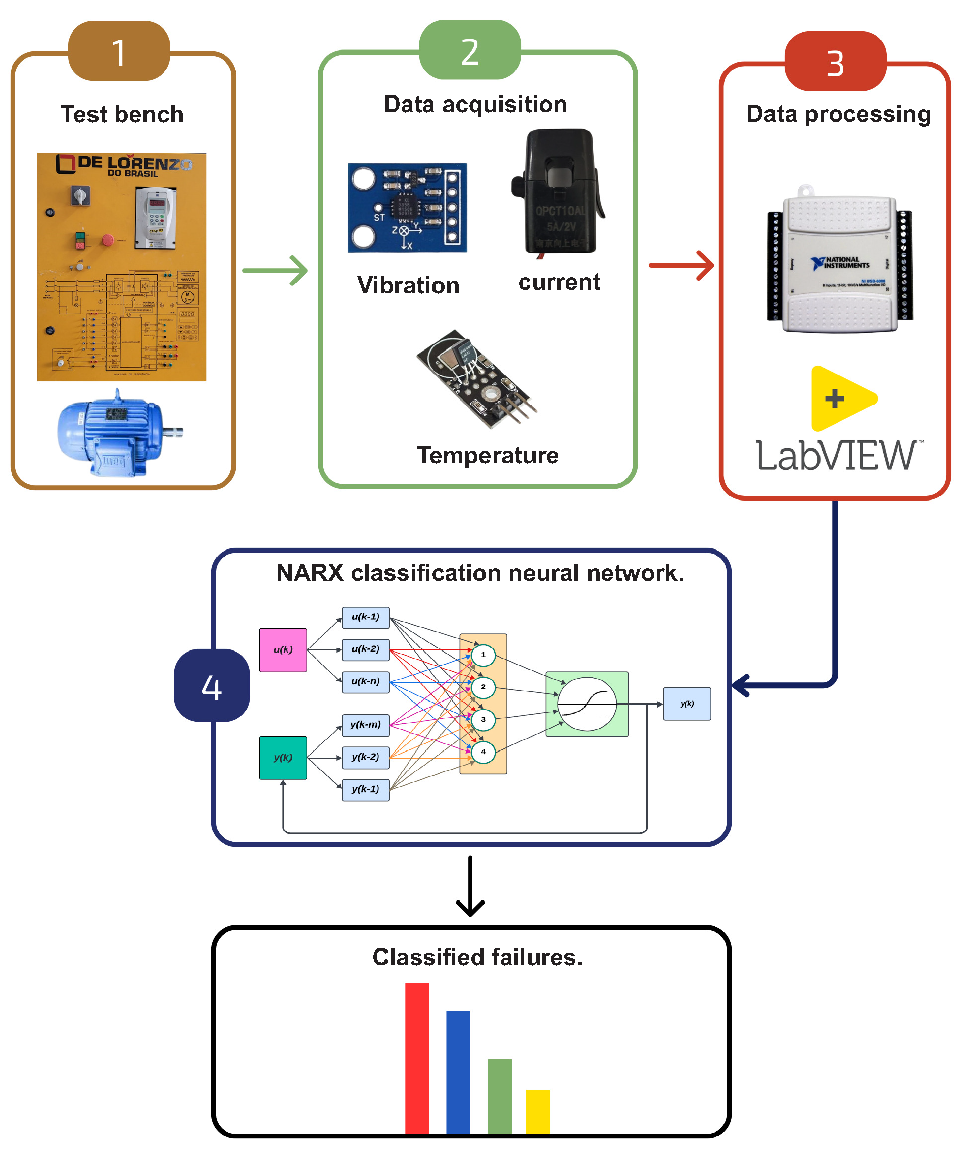
This section covers a detailed description of the methodology adopted in the development of the monitoring and fault diagnosis system for three-phase induction motors. For this research, we used a database composed of stator current, vibration, and temperature signals, collected from a Three-Phase Induction Motor (MIT) installed in a testing laboratory. The tests were conducted under normal operating conditions, as well as in fault situations, including stator voltage unbalance, shaft unbalance, and bearing defects.
The subsequent sections aim to detail the procedures, materials, and methods used in signal acquisition, as well as explain how the faults were emulated.
Figure 7.
Process flowchart.
4.1. Materials - Test Bench
The bench used to carry out the experiments is the DLB MAQ-RN, manufactured by the company De Lorenzo. This bench is equipped with the necessary resources to carry out the signal acquisition and fault emulation procedures efficiently and accurately, enabling reliability in the results, and is composed of a WEG brand frequency inverter model CFW-09 with power HP and 10A current and a cage-type induction motor.
4.2. Materials - Data Collection
Data collection was carried out using five sensors, strategically installed in the engine. These include three current sensors distributed across the three phases that power the motor, providing a comprehensive analysis of its electrical performance. Furthermore, a temperature sensor was positioned to monitor thermal variations, while an accelerometer-type vibration sensor was used to evaluate the mechanical oscillations of the system. This variety of sensors allows for comprehensive data collection, offering valuable insights into many aspects of engine operation.
4.2.1. Current Measurement
To measure three-phase currents in the stator, non-invasive current sensors based on the Hall effect were used, specifically the 5A/2V model - OPCT 10AL.
Converting AC voltage signal to DC
The sensor has been calibrated to measure the maximum alternating current of 5A AC. This 5A value is the RMS value, which is also called the effective value. The RMS value is equal to the maximum value that the current can reach (peak current) divided by the square root of two. At the sensor output, the induced current signal is similar to that in Figure 11.
In Figure 11, an alternating voltage signal oscillating between positive V and negative V is shown. However, the DAQ-6008 interface device, being powered by a, is capable of measuring signals within the range of 0 to 5V. Therefore, it is necessary to adjust the signal so that the signal variation is in the range of 0V to 5V. To achieve this adjustment, initially, a voltage divider was implemented using the 5V power supply provided by the DAQ-6008 device. In this context, we chose to configure resistors R1 and R2 with the same value, both 10k.
Figure 12 illustrates the signal conditioning circuit and Figure 13 illustrates the conditioning board.
This choice guarantees that the voltage across them is equal, as the 5V coming from the device will be distributed evenly between them as can be seen in Figure 14.
4.2.2. Vibration Sensor
The GY-61 DXL335 3-axis accelerometer module is an advanced sensor that utilizes the ADXL335 integrated circuit. This triaxial accelerometer offers exceptional performance, characterized by a very low level of noise and energy consumption. With a full detection range of g, the sensor is capable of measuring both static accelerations due to gravity, in tilt sensing applications, and dynamic acceleration resulting from movement, impact or vibration.
4.2.3. Temperature Measurement
To measure the engine temperature, the LM35DZ temperature sensor module was used. The LM35DZ temperature sensor consists of a high-precision integrated circuit, whose output voltage varies linearly about the temperature in degrees Celsius. The LM35DZ device eliminates the need for external calibration or adjustments, providing remarkable accuracies of C at room temperature and C over a wide thermal range, ranging from C to C.
4.3. Data Processing
During the data collection stage, the sensors were connected to the DAQ - USB-6008 interface board, manufactured by National Instruments, to capture the signals, which were later read in the LabVIEW software. ADAQ - USB-6008 is an affordable and user-friendly solution for interfacing input and output signals with a personal computer. Connectable via a simple USB cable, this board offers a direct and efficient connection to the PC.
4.3.1. Labview Block Diagram Code
Programming on the LabVIEW platform was carried out through a graphical interface in the block diagram, where each block represents a specific LabVIEW function. In the case of the vibration, current, voltage, and temperature monitoring program, the analyses are continuous, therefore it is necessary to implement a loop (while) to execute in cycles. This loop is interrupted when a stop condition is reached, such as pressing the stop button.
The graphs are generated according to the selected quantity. In this process, the graphics block identifies one of the signals given in its input and applies a fast Fourier transform (FFT) to the signal. Subsequently, the data is presented in both the time and frequency domains, allowing visualization in the corresponding graphs. In addition to the graphical representation, the data is exported to Excel, where it is compiled into a database. This database is essential to feed the artificial intelligence algorithms used later.
Figure 18 illustrates the block diagram developed in LabVIEW software to perform signal processing. The diagram is divided into five blocks: block 1, DAQ assistant, is responsible for configuring the ports on the data acquisition board; Block 2 is responsible for configuring the reading of the vibration signal for the three axes of the accelerometer and generating graphs to display these signals in both time and frequency; block 3 has the same function as block 2, but for the current signal, generating similar graphs; block 4 is responsible for configuring the temperature signal reading and displaying this signal through a graph; in block 5, the while loop time and the determination of the stopping criteria is configured.
4.4. Methodology of the Fault Detection Process
This section describes the methodology adopted to build the database from the signals collected in the engine, as well as the process of normalizing this data and the development of the fault classification algorithms addressed in this work.
For training, validation, and testing of the neural network, a set of data was constructed from the signals collected by the sensors installed in the engine, having a csv table format with columns referring to the network’s input and output data. The data set, in turn, was subdivided into three sets, one for training, another for validation, and another for testing, following the proportions 70%; 15%; 15%.
After creating the data sets, they were normalized. Normalization is a process by which data is adjusted to a scale with a range between zero and one. This practice is crucial, as neural network models tend to perform optimally when inputs are in this range. Equation 11 illustrates the formula used to calculate the normalized value of input X.
4.4.1. NARX Neural Network for Classification
The NARX (Nonlinear AutoRegressive with Exogenous inputs) Neural Network is a powerful architecture for modeling nonlinear dynamical systems, enabling accurate predictions and adaptation to changing operating conditions. This work explores significant modifications to network parameters, such as the cross-entropy loss function and the use of the softmax activation function at the output, specifically aimed at diagnosing faults in three-phase induction motors.
Changes in the parameters of the NARX neural network open up significant opportunities for its application in categorical multi-class fault classification tasks. Although the original NARX framework is widely used for time series forecasting and modeling, these modifications allow it to be adapted for classification problems, especially where temporal characteristics are essential for identifying fault patterns and characteristics.
One of the main advantages of this approach is the ability to use the architecture of neural networks to extract and learn complex representations of input data, including past temporal information. With modifications to the parameters, the network can focus on identifying patterns and characteristics relevant to classifying faults.
Furthermore, adopting a NARX network for categorical multiclass classification enables the use of specific evaluation techniques and metrics for classification problems, such as precision, recall, F1-score, and confusion matrix. This allows for a more accurate assessment of network performance in identifying and classifying different types of faults.
Another significant advantage is the flexibility of this approach. By using a modified neural network structure, it is possible to easily tune the network architecture, experiment with different configurations of hidden layers, activation functions, and training methods, optimizing the network performance for the specific fault classification problem.
In summary, when using a NARX network in the categorical multiclass classification of faults, benefits such as the ability to extract relevant temporal information, the use of specific classification techniques, and the flexibility to adjust the network architecture are obtained, better meeting the needs of the problem in question.
Figure 19 illustrates the topology of the NARX neural network for categorical multiclass classification.
5. Results
Next, the results obtained from the proposed methodology application will be presented, which aim to evaluate the performance of the NARX Neural network, through comparisons of dynamic response and efficiency. These results were obtained through tests conducted on the experimental bench located in the Automation and Control Laboratory of the Federal University of Rio Grande do Norte. Four scenarios were established for data collection, which will be described below. Then the NARX neural network will be trained, validated, and tested based on this collected data.
5.1. Scenarios for Data Collection
The programmed failure test followed a script with the development of five different scenarios for case studies, aiming to identify failures in the electric motor through signal analysis. The scenarios were developed to represent various engine operating conditions, including normal operating situations and simulated failures, such as shaft unbalance, bearing damage, and stator current unbalance. The tests were carried out at three speeds: 900 RPM, 1200 RPM, and 1800RP M. this article, only data for the 1800 RPM speed is presented.
5.1.1. Scenario 1: Collecting Data from the Engine in Good Operating Conditions
This scenario serves as a reference point, representing normal engine operation under ideal conditions. Vibration, electrical current in the phases, and temperature signals were collected. Figure 20 illustrates the engine with the sensors installed. Figure 21 and Figure 23 respectively illustrate the signals in the time domain for vibration and current signals, while Figure 22 and Figure 24 illustrate the signals in the frequency for the same signals. Figure 25 illustrates the temperature in ideal engine conditions.
5.1.2. Scenario 2: Motor Data Collection with Shaft Unbalance
Engine unbalance is characterized by the uneven distribution of mass around the axis of rotation of the engine shaft. Due to this imbalance, the centripetal forces generated during the operation increase bearing wear. The phenomenon is typically observed in all rotating machines and is identified by an amplitude peak at the shaft rotation frequency, which is shown in the frequency spectrum.
To create a dynamic eccentricity that corresponds to an unbalance in the motor shaft for this scenario, a mass weighing 28 g was used. Figure 26 shows its fixation on a disc coupled to the motor shaft. The vibration signal that results from the induced unbalance is shown in Figure 27. The vibration signal for this particular case presents a sinusoidal pattern as is typical of an unbalance. Figure 28 illustrates the frequency domain analysis, showing an amplitude peak at the shaft rotation frequency that corresponds to 30 mechanical Hz for a speed of 1800 RPM. The current signal in the time and frequency domains is shown in Figure 29 and Figure 30, and the motor temperature variations are shown in Figure 36. These graphs provide more information about the behavior of the motor with the shaft unbalanced. Comparing the current signal with the unbalanced shaft and the current signal with the motor in ideal conditions, it can be seen that the current underwent a small change, changing from A to 3A. The temperature remained within the same variation range.
5.1.3. Scenario 3: Data Collection from the Engine with Failed Bearings
Bearings essentially consist of inner and outer rings, rolling elements (such as balls or rollers), and a cage. This component is widely recognized as one of the most frequent causes of failures in rotating machines. The premature emergence of failures is generally associated with inadequate operating conditions. Among the main factors that contribute to early bearing failures are dirt and water contamination, bearing overload, lack of lubrication, and inadequate procedures during assembly of the bearing assembly. The most common bearing failures tend to occur in the inner and outer races, as well as the balls or rollers. Fault detection is usually performed by transforming the signal from the time domain to the frequency domain. This approach is adopted for several reasons. Firstly, machine faults are identified in the signal spectrum through peaks at characteristic frequencies, as each component or fault emits a unique frequency vibration. The intensity of the characteristic harmonic indicates the presence or severity of such a fault [26].
There are four basic frequencies generated by bearing defects:
- BPFI Defect. Internal ring passage frequency.
- BPFO Defect. Ring outer pass frequency.
- BSF defect. Rolling element passing frequency.
- FFT defect. Fundamental frequency (cage frequency).
On the SKF website, one of the main bearing manufacturers, a valuable online tool is available for calculating rotational and over-rolling frequencies. This calculator allows the determination of bearing frequencies based on manual input of bearing geometric data. For comparison purposes with the data obtained from vibration signal analysis to identify defective bearings, calculations were carried out for the frequency of 30 mechanical Hz which corresponds to 1800 RPM for the Z and Z bearings.
Figure 32 and Figure 33 show the calculated rolling frequencies. Figure 34 shows the damaged 6403-2Z and 6404-2Z bearings used in this test scenario. The vibro signal is shown in Figure 35 in the time domain and Figure 36 in the frequency domain. The current signal is shown in Figure 37 in the time domain and Figure 38 in the frequency domain. The engine temperature for this scenario is illustrated by Figure 39.
Figure 32.
Failure occurrence frequencies for bearings-6203-2Z.
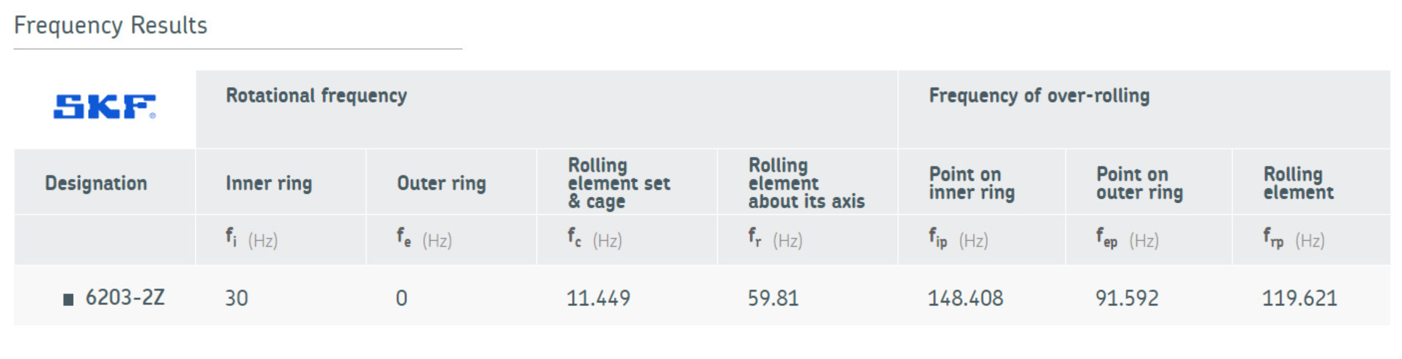
Figure 33.
Failure occurrence frequencies for bearings-6204-2Z.
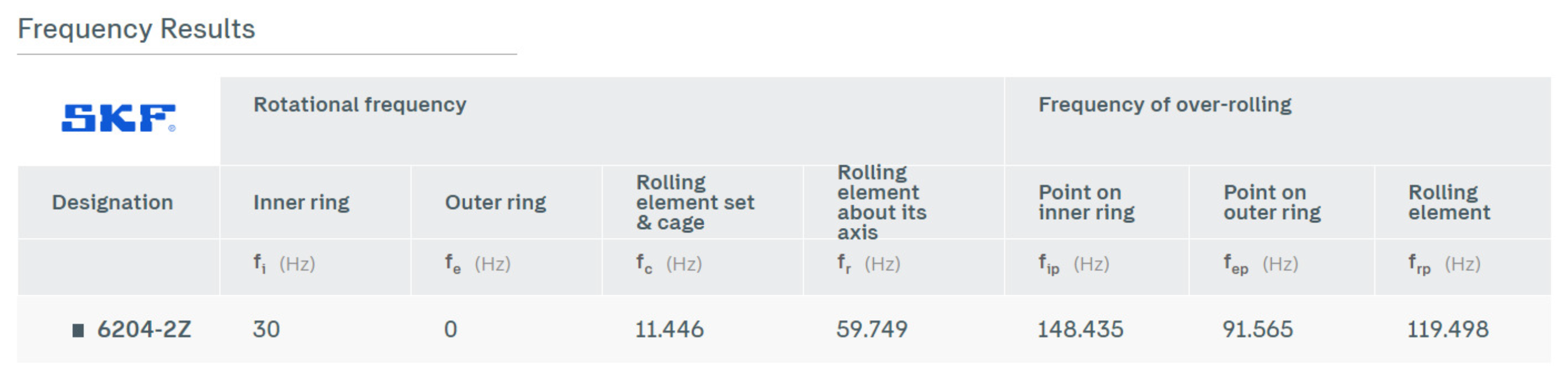
Figure 34.
Bearings with defects-6203-2Z/6204-2Z.
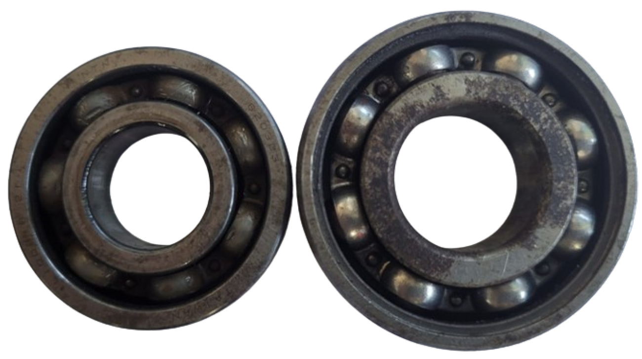
Figure 35.
Vibration signal in the time domain.
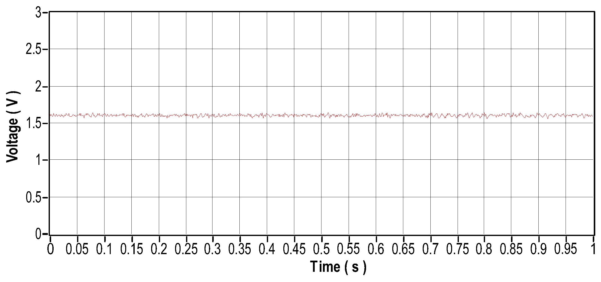
Figure 36.
Vibration signal in the frequency domain.
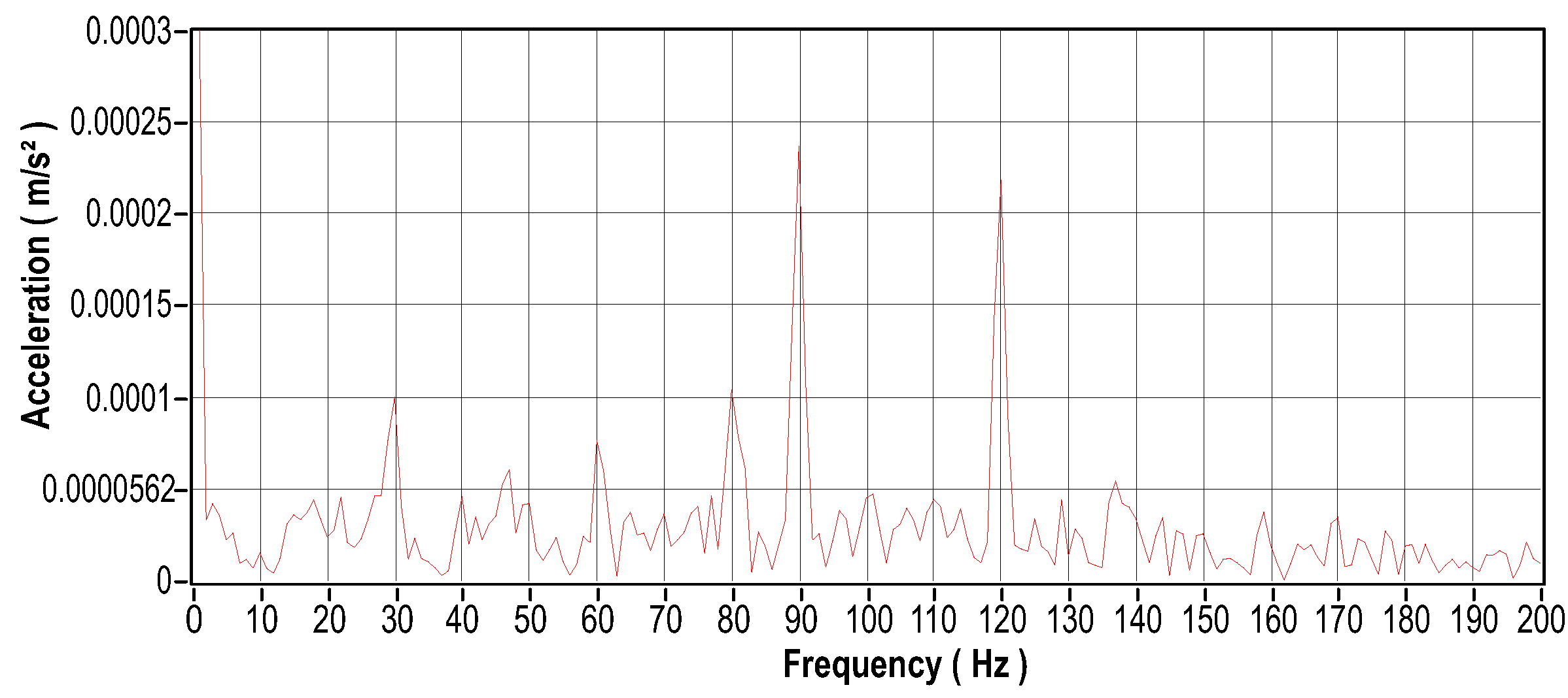
Figure 37.
Current signal in the time domain.
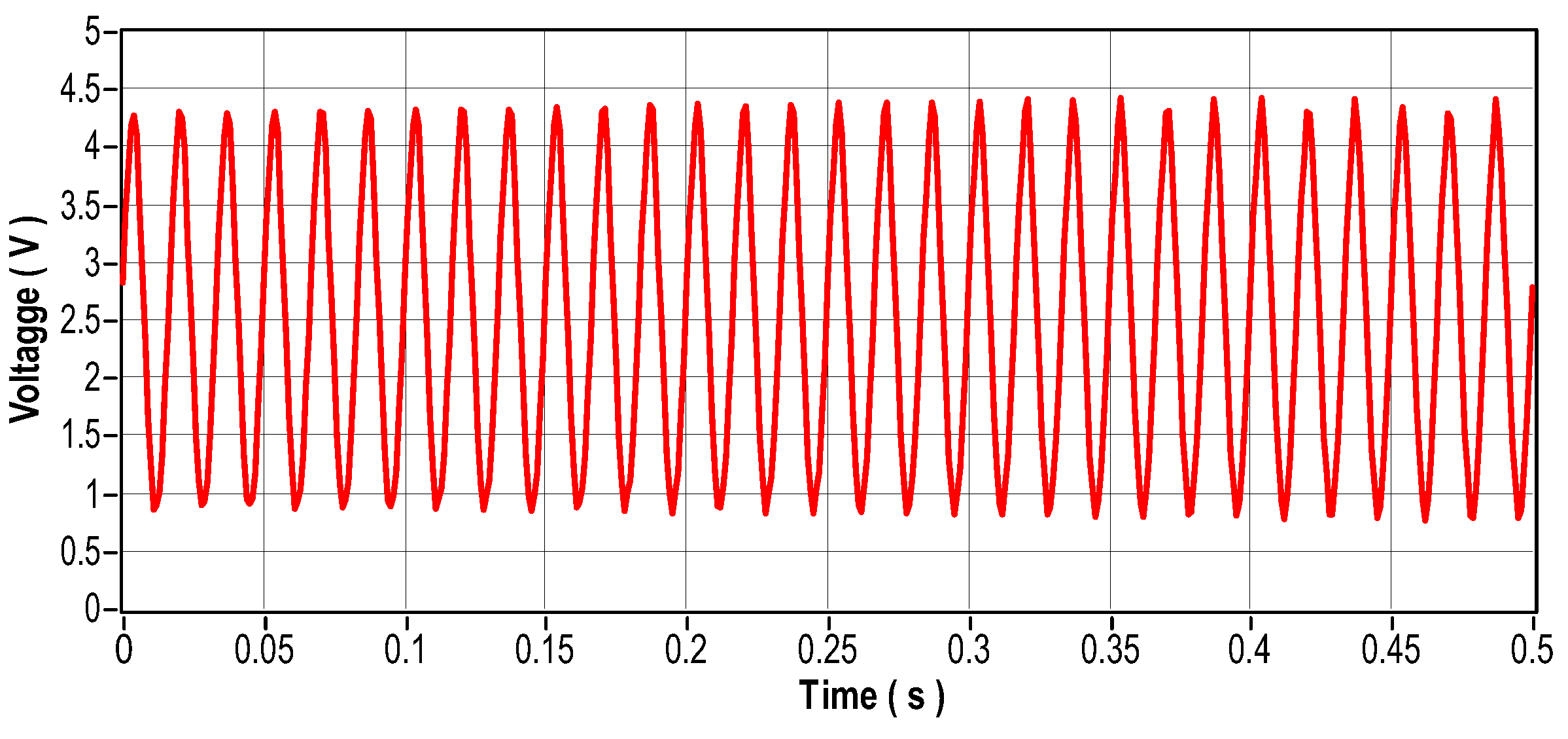
Figure 38.
Current signal in the frequency domain.
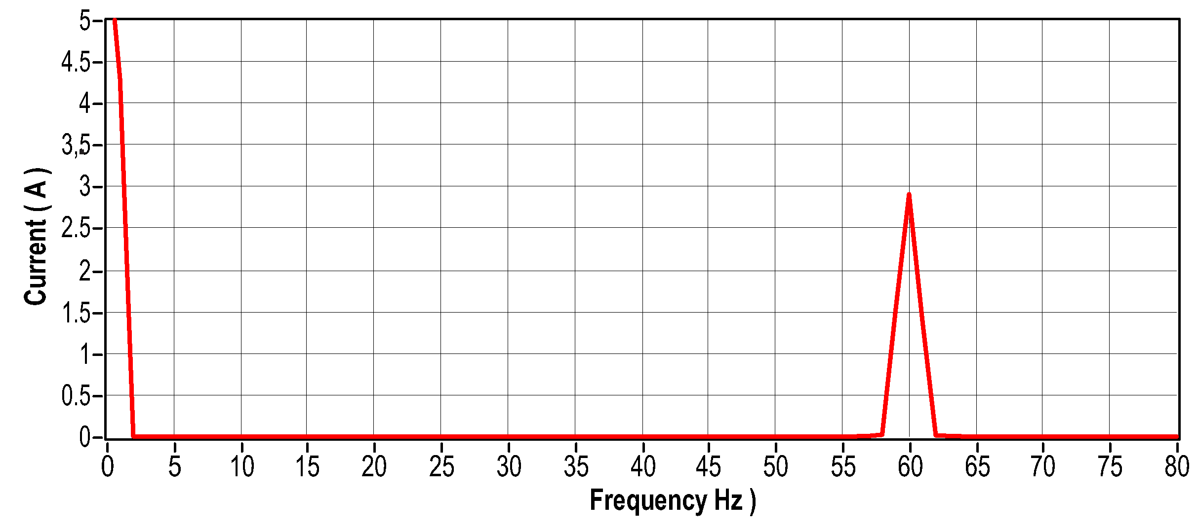
Figure 39.
Temperature signal of motor bearing with defect.
5.1.4. Scenario 4: Motor Data Collection with Stator Current Imbalance
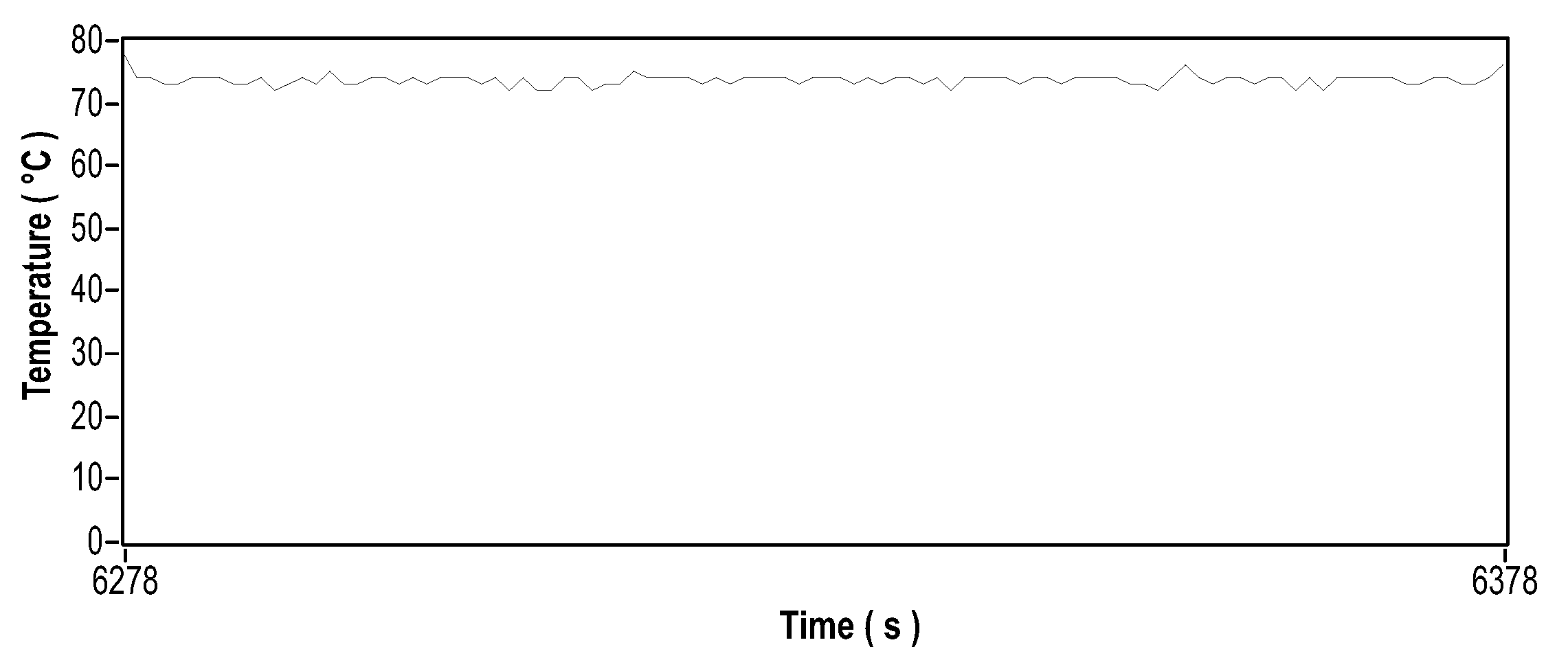
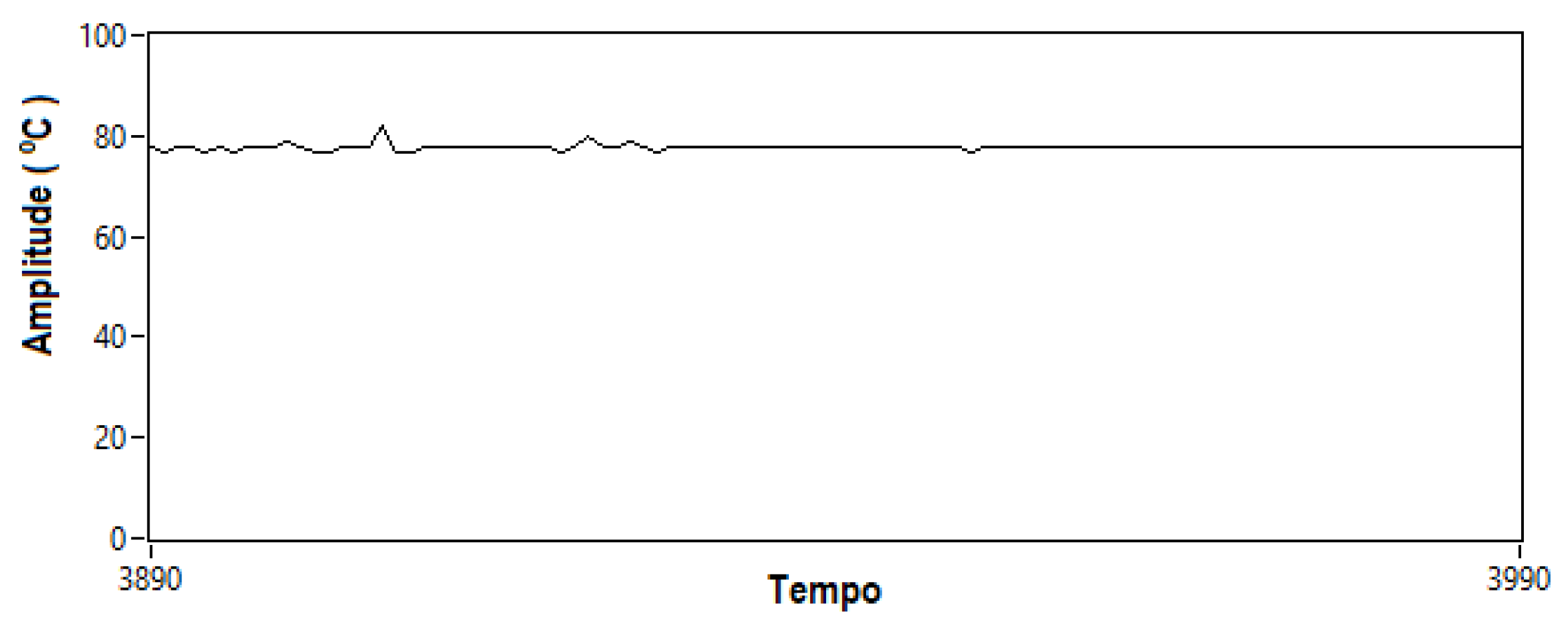
When the stator currents in an electric motor become unbalanced, several problems can arise, including overheating, excessive vibration, decreased efficiency, and premature wear. To investigate these phenomena, an approach was adopted: a bank of resistors with an ohmic load of 83.5 was connected in series with one of the stator coils, to cause variations in currents. Figure 40 shows the arrangement of the resistor bank used to induce such variations. Figure 41 (in the time domain) and Figure 42 (in the frequency domain) show the vibration signals recorded for this scenario. Figure 43 to Figure 48 show the current readings, both in the time and frequency domains, corresponding to the three phases of the system. Finally, Figure 49 illustrates the temperature behavior for this same experimental scenario.
Figure 40.
Bank of resistors for current unbalance.
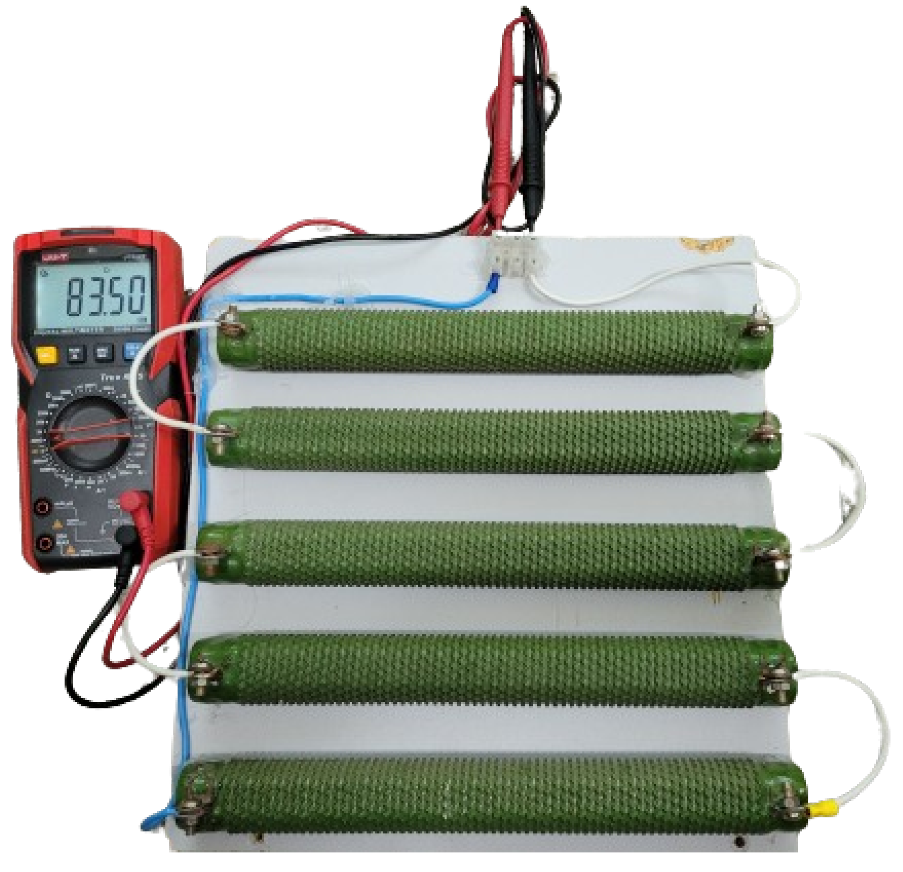
Figure 41.
Vibration signal in the time domain.
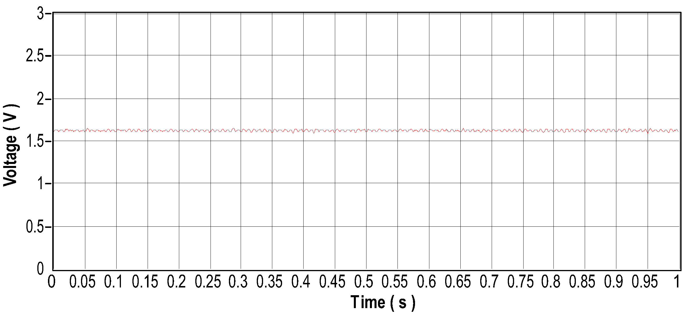
Figure 42.
Vibration signal in the frequency domain.
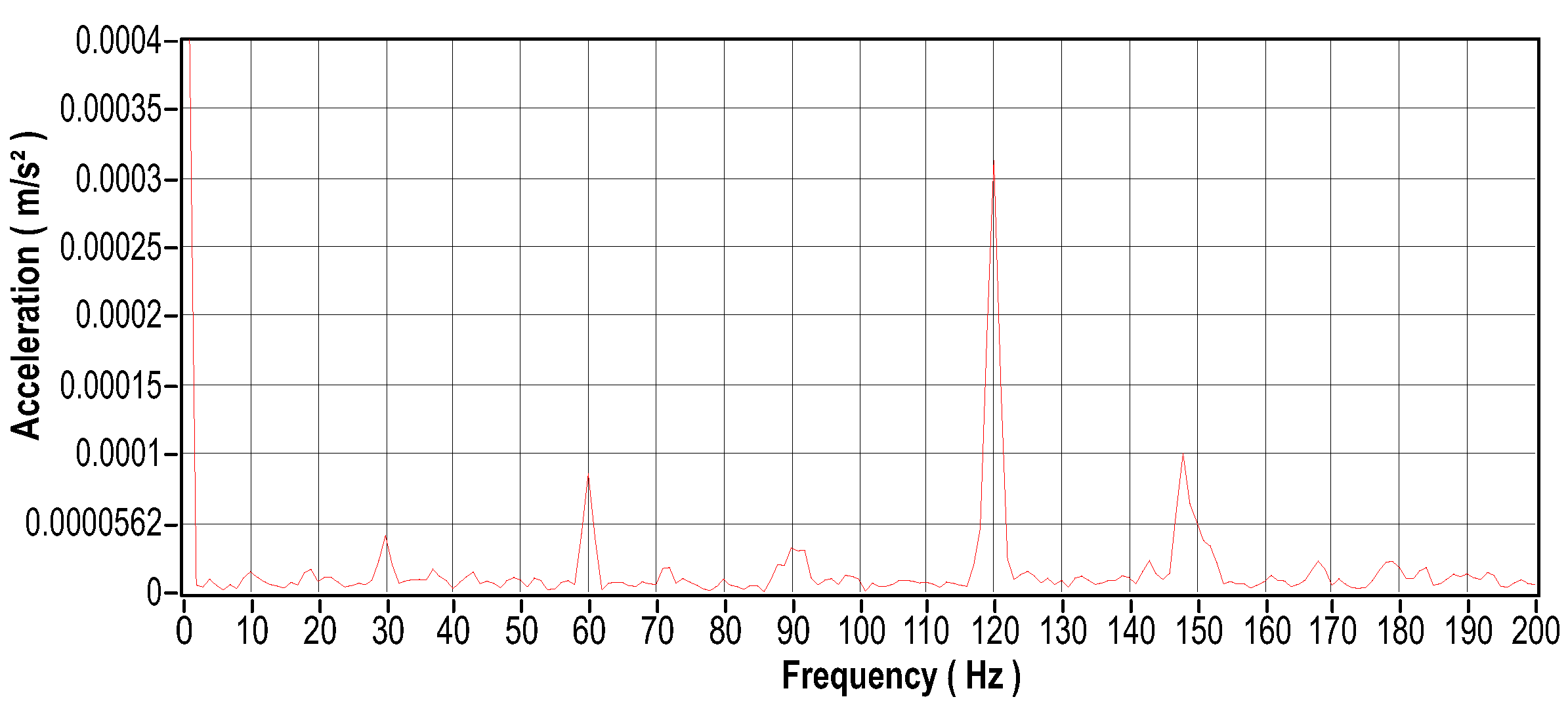
Figure 43.
Current signal in the time domain-Phase 1.
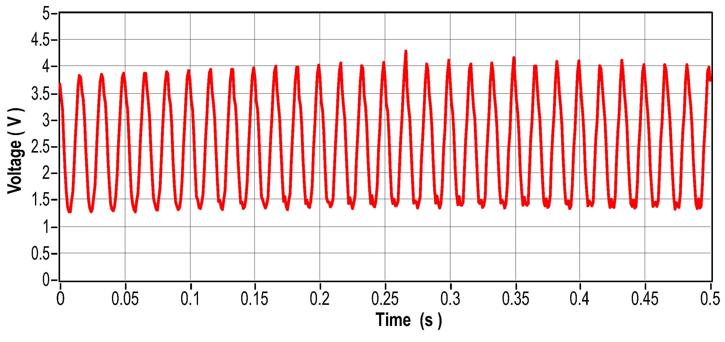
Figure 44.
Current signal in the frequency domain-Phase 1.
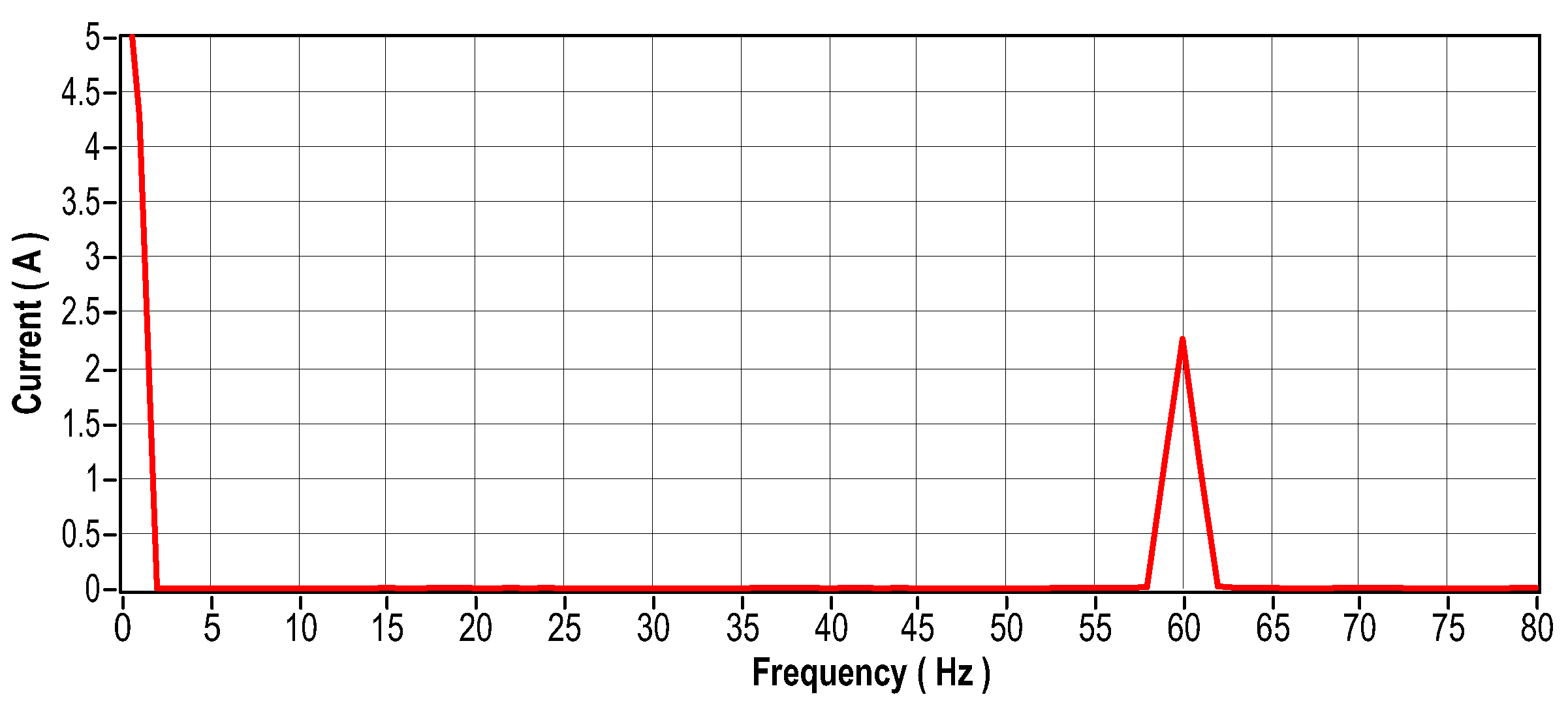
Figure 45.
Current signal in the time domain-Phase 2.
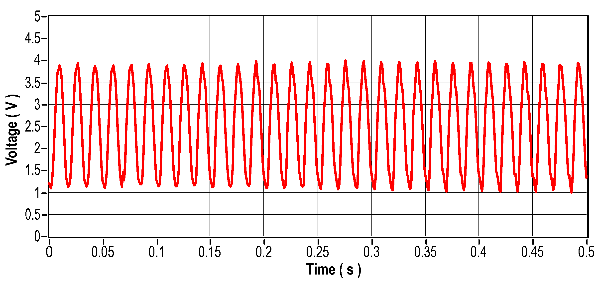
Figure 46.
Current signal in the frequency domain-Phase 2.
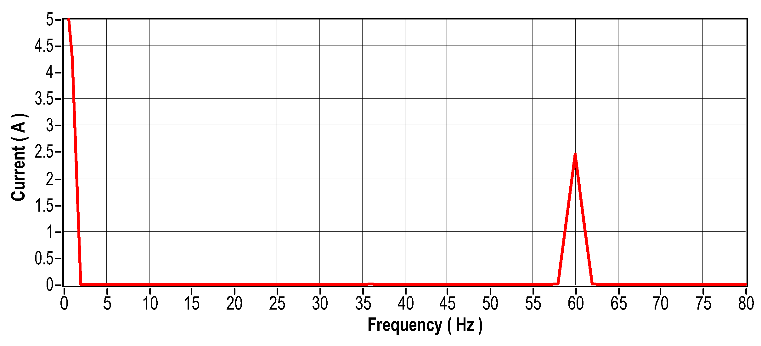
Figure 47.
Current signal in the time domain-Phase 3.
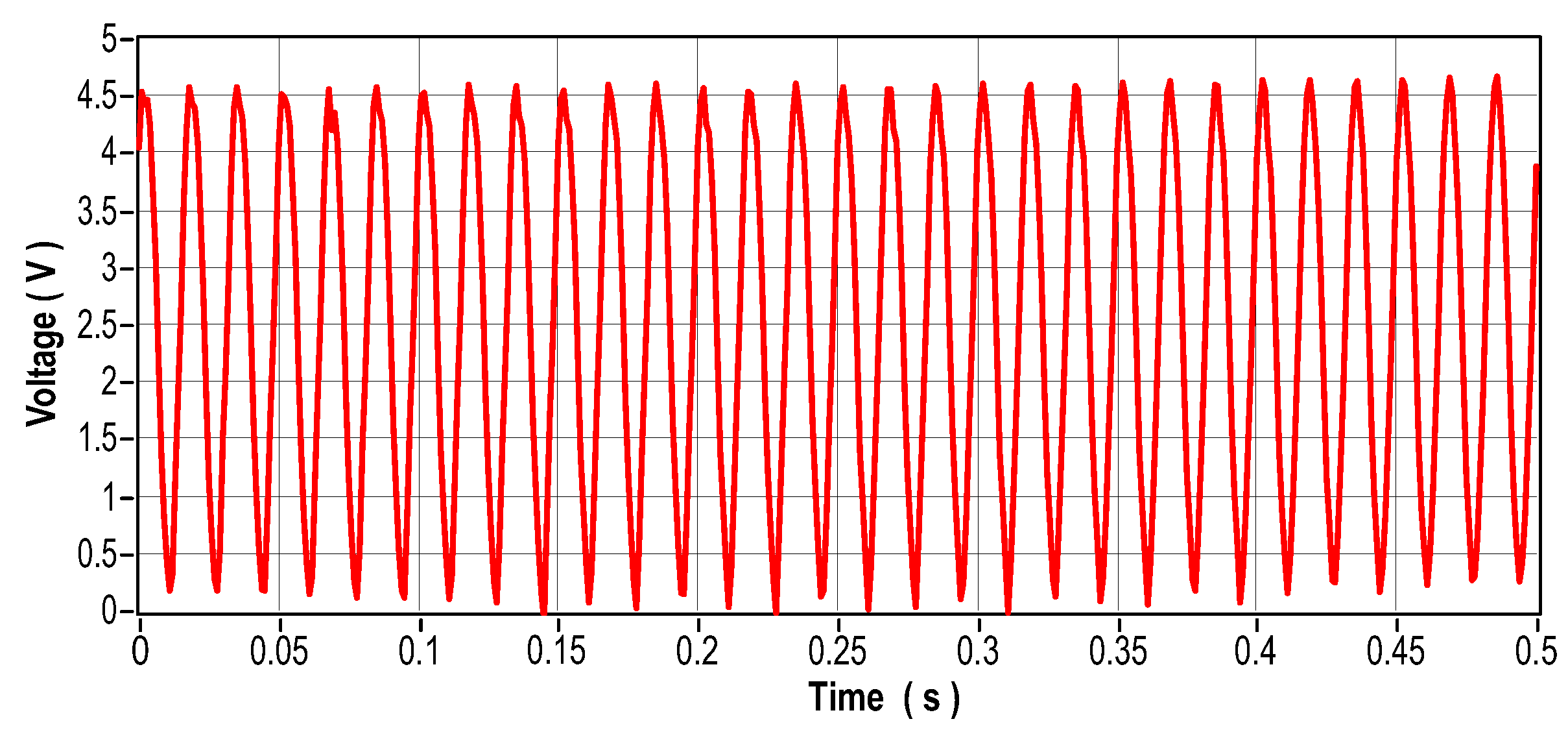
Figure 48.
Current signal in the frequency domain-Phase 3.
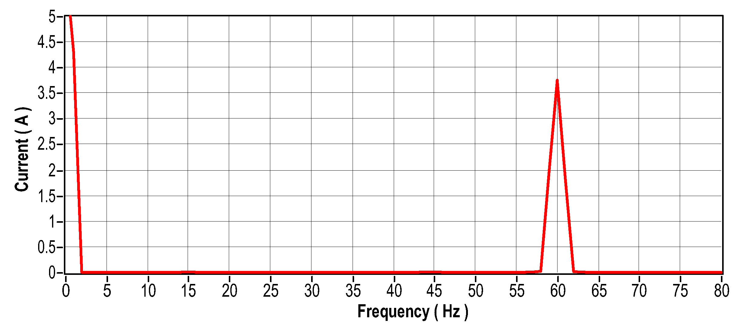
Figure 49.
Temperature signal for phase unbalance motor.
5.2. NARX Neural Network Training
The NARX network stands out for its use of recurrence and temporal delays in both inputs and feedback. During project development, it is essential to define the amount of delays and adjust other network-specific parameters, such as the number of neurons in each layer, the activation function of each neuron, and the learning algorithm used.
To obtain the best results, the NARX neural network was subjected to multiple trainings in a scan loop, to determine the optimal number of neurons in the two hidden layers and the delays at both inputs and output. The training was carried out with datasets of 50 thousand events, collected from the four previously mentioned scenarios, using Matlab® software in offline mode. After training, the best network configuration was identified and subjected to testing and validation to evaluate its generalization capacity. Four different types of network outputs were examined, corresponding to different engine operating conditions: Faultless motor, unbalanced defect, Defective bearings, and Defective stator.
During the optimization process, the following parameters were adjusted between 1 and 30 to find the optimal network configuration:
- Delay = Delay steps for the input data.
- Feedback = Output feedback delay steps.
- Neurons-H1 = Number of neurons in the first hidden layer.
- Neurons-H2 = Number of neurons in the second hidden layer.
To achieve the best network performance the following parameter settings were determined:
- TrainFcn = ’trainscg’; - "Scaled Conjugate Gradient" (SCG).
- TrainParam.epochs = 500; - Maximum number of training epochs.
- PerformFcn = ’crossentropy’; - Categorical cross-entropy cost function.
- layers1.transferFcn = ’logsig’; - Logistic sigmoid function 1st hidden layer.
- layers2.transferFcn = ’logsig’; - Logistic sigmoid function 2nd hidden layer.
- layersend.transferFcn = ’softmax’; - Output activation function.
To train the network, a balanced data set was used, ensuring that the number of examples of each type of failure was equal. After several training cycles, the optimal network configuration was identified, as illustrated in Table 6. Figure 50, confusion matrix, and Figure 51, ROC curve, illustrate the network’s performance for the test set. Figure 52 illustrates the class graph showing the number of faults classified and Table 7 presents the performance metrics of the trained network.
Once the best network had been obtained, it was necessary to validate it with new data from the engine signals. The tests described below aim to validate the NARX network implemented and trained previously to identify the four faults described in previous sections.
5.2.1. Case 1: Network Test - Motor without Failures.
For this first network validation scenario, a new dataset made up of signals collected from the engine in good operating conditions was inserted into the inputs of the NARX neural network. For this type of failure, the network responded well, achieving a performance of 94.2%. Figure 53 to Figure 55 and Table 8 illustrate the network’s overall performance.
5.2.2. Scenario 2 - Validation of the NARX Network - Unbalance Fault
.
For this second network validation scenario, a new dataset made up of signals collected from the motor with an unbalanced shaft was inserted into the inputs of the NARX neural network. For this type of fault, the network responded well, achieving a performance of 95%. Figure 56 to Figure 58 and Table 9.
5.2.3. Scenario 3 - Validation of the NARX Network - Defective Bearings
5.2.4. Scenario 4 - Validation of the NARX Network - Faulty Stator
For this fourth network validation scenario, a new dataset made up of signals collected from the motor with unbalanced stator phases was inserted into the inputs of the NARX neural network. For this type of fault, the network responded well, achieving a performance of 98%. Figure 62 to Figure 64 and Table 11.
6. Discussion
The NARX model was used as a viable tool for diagnosing and classifying faults in three-phase induction motors. After a scanning process to find the best network, with the ideal number of neurons for the two hidden layers and the delays for the inputs and outputs, the selected network was subjected to a series of validation tests. The results of these tests showed that the network has an excellent generalization capacity in all the situations evaluated. The data obtained proves the network’s excellent performance in classifying faults, even when new data is presented. Table 12 shows the hit rate for each engine condition in the four test scenarios discussed in Section 5.2.
In the work by [7], the proposal to use a support vector machine algorithm to diagnose faults in induction motors achieved an average accuracy of 98.85%.
In the work by [12], the proposal was a Perceptron Multilayer Neural Network (PMC) consisting of two hidden layers with 7 neurons each, in addition to the output layer with 2 neurons for classification of faults in three-phase induction motors, being validated with data acquired from machines not used in the training processes. The proposed network achieved an accuracy of 97%.
By analyzing the results obtained from previous studies, it can be concluded that the NARX neural network developed for classifying faults in three-phase induction motors achieved the proposal set out in this article.
7. Conclusions
This article focuses on the early identification of faults through accurate diagnosis and classification of faults in three-phase induction motors, using artificial intelligence techniques, through the analysis of current, temperature, and vibration signals. The development and use of an Exogenous AutoRegressive Neural Network (NARX) to classify motor faults obtained satisfactory results, validating the effectiveness of the proposed method. The case study showed that the proposed method for developing a NARX classification model is very efficient in identifying faults in MITs. Among the faults classified with the highest accuracy, the proposed model stood out in the defective bearings detections, achieving an accuracy of 98% for new data. In this research, the neural network was developed in the Matlab® environment, which demonstrated excellent performance. However, for future research, it is important to consider the adapt need the code to a language that can be incorporated into embedded systems for real-time detection.
Author Contributions
V.G.D.A., J.M.M.V. and A.O.S. conceived and designed the study; V.G.D.A., J.M.M.V., A.O.S.B. and D.A.D.M. F. were responsible for the methodology; V.G.D.A., A.O.S.B., R.d.A.T. and D.A.d.M.F. performed the simulations and experiments; V.G.D.A., A.O.S.B., J.M.M.V., E.R.L.V., R.d.A.T. and D.A.d.M.F. reviewed the manuscript and provided valuable suggestions; V.G.D.A., J.M.M.V., E.V.R.L.V., R.d.A.T. and D.A.d.M.F. wrote the paper; J.M.M.V. and A.O.S. were responsible for supervision. All authors have read and agreed to the published version of the manuscript.
Funding
This research was funded and supported by the Coordenação de Aperfeiçoamento de Pessoal de Nível Superior—Brasil (CAPES)—Finance and Conselho Nacional de Desenvolvimento Científico e Tecnológico (CNPq).
Conflicts of Interest
The authors declare no conflicts of interest.
Abbreviations
The following abbreviations are used in this manuscript:
| NARX | Nonlinear AutoRegressive Exogenous inputs |
| SVM | Support Vector Machine |
| TIM | Three-phase induction motor |
| ANN | Artificial Neural Network |
| FIS | Fuzzy Inference System |
| GA | Genetic Algorithm |
| MLP | Multilayer Perceptron |
| DC | direct current |
| ML | Machine Learning |
| IM | Induction Motors |
| RNN | Recurrent Neural Network |
| FFT | Fast Fourier transform |
| MSE | Mean Square Error |
| LM | Levenberg-Maquardt |
References
- Graciola, C.L.; Goedtel, A.; Castoldi, M.F.; Gentil, M.G.; Souza, W.A.; Vitor, A.L.O. An Efficiency Study of a Three-Phase Induction Motor Through Predictive Control Strategies. In Proceedings of the 2023 15th IEEE International Conference on Industry Applications (INDUSCON); 2023; pp. 899–905. [Google Scholar] [CrossRef]
- Santos, M.S.; Paz, E.H.; Aguiar, V.B.; Pontes, R.T. Non-invasive monitoring system for analysis of energy efficiency of three-phase induction motors. In Proceedings of the 2022 Workshop on Communication Networks and Power Systems (WCNPS); 2022; pp. 1–6. [Google Scholar] [CrossRef]
- Ojaghi, M.; Mohammadi, M. Modeling eccentricity faults with axial asymmetry in three-phase induction motors. In Proceedings of the IECON 2016 - 42nd Annual Conference of the IEEE Industrial Electronics Society; 2016; pp. 1524–1529. [Google Scholar] [CrossRef]
- Broniera, P.J.; Gongora, W.S.; Goedtel, A.; Godoy, W.F. Diagnosis of stator winding inter-turn short circuit in three-phase induction motors by using artificial neural networks. In Proceedings of the 2013 9th IEEE International Symposium on Diagnostics for Electric Machines, Power Electronics and Drives (SDEMPED); 2013; pp. 281–287. [Google Scholar] [CrossRef]
- Okpo, E.E.; Le Roux, P.F.; Nnachi, A.F. Induction Motor Fault Identification using Support Vector Machine. In Proceedings of the 2023 6th International Conference on Renewable Energy and Power Engineering (REPE); 2023; pp. 168–174. [Google Scholar] [CrossRef]
- Xuhong, W.; Yigang, H. Diagonal recurrent neural network based on-line stator winding turn fault detection for induction motors. In Proceedings of the 2005 international conference on electrical machines and systems. IEEE; 2005; Vol. 3, pp. 2266–2269. [Google Scholar]
- Aydin, I.; Karakose, M.; Akin, E. Artificial immune based support vector machine algorithm for fault diagnosis of induction motors. In Proceedings of the 2007 International Aegean Conference on Electrical Machines and Power Electronics. IEEE; 2007; pp. 217–221. [Google Scholar]
- Cho, H.C.; Knowles, J.; Fadali, M.S.; Lee, K.S. Fault detection and isolation of induction motors using recurrent neural networks and dynamic Bayesian modeling. IEEE Transactions on Control Systems Technology 2009, 18, 430–437. [Google Scholar] [CrossRef]
- Vitor, A.L.O.; Oliveira, F.M.; Ronqui, L.A.; Goedtel, A.; Scalassara, P.R.; Silva, S.A.O.; Vallim, M.B.R. Detecção de falhas elétricas em motores de indução utilizando rede radial basis function. Anais do XX Congresso Brasileiro de Automátican 2014, 46, 37–42. [Google Scholar]
- Jagadanand, G.; Dias, F.L. ARM based induction motor fault detection using wavelet and support vector machine. In Proceedings of the 2015 IEEE International Conference on Signal Processing, Informatics, Communication and Energy Systems (SPICES). IEEE, 2015, pp. 1–4.
- Sobrinho, C. A. N.; Lima Filho, A.C. .d.S.A.P.C.B.J.N..d.S.J.F..M.M. Transformada Wavelet para detecção de barras quebradas em Motores de Indução Trifásicos. Revista Principia-Divulgação Científica e Tecnológica do IFPB 2018, 1, 72–83. [Google Scholar] [CrossRef]
- Gongora, W.S.; Goedtel, A.; da Silva, S.A.O.; Graciola, C.L. Neural approach to fault detection in three-phase induction motors. IEEE Latin America Transactions 2016, 14, 1279–1288. [Google Scholar] [CrossRef]
- WEG, S. Specification Guide: Electric Motors. In Portuguese language, 2023.
- Guedes, J.J.; Goedtel, A.; Castoldi, M.F.; Sanches, D.S.; Serni, P.J.A.; Rezende, A.F.F.; Bazan, G.H.; de Souza, W.A. Three-phase induction motor fault identification using optimization algorithms and intelligent systems. Soft Computing 2024. pp. 1–16. [Google Scholar] [CrossRef]
- Silva, M.A.; Lucena-Junior, J.A.; da Silva, J.C.; Belo, F.A.; Lima-Filho, A.C.; Ramos, J.G.G.d.S.; Camara, R.; Brito, A. Sensorless Speed Estimation of Induction Motors through Signal Analysis Based on Chaos Using Density of Maxima. Entropy 2024, 26, 361–361. [Google Scholar] [CrossRef] [PubMed]
- Lucas, G.B.; de Castro, B.A.; Rocha, M.A.; Andreoli, A.L. Three-phase induction motor loading estimation based on Wavelet Transform and low-cost piezoelectric sensors, Measurement. Measurement 2020, 164, 107956. [Google Scholar] [CrossRef]
- Oliveira, R.F. Artificial Intelligence in Portuguese; Editora e Distribuidora Educacional S.A.: Londrina, 2018. [Google Scholar]
- Santos, G.R.; Brito, J.N.; Santana, C.; Lara, H. Monitoramento de motores trifásicos através de inteligência artificial. Anais do XVIII Congresso Nacional de Engenharia Mecânica e Industrial 2018, 2. [Google Scholar]
- Preethi, I.; Suryaprakash, S.; Mathankumar, M. A State-of-Art Approach on Fault Detection in Three Phase Induction Motor using AI Techniques. In Proceedings of the 2021 5th International Conference on Computing Methodologies and Communication (ICCMC); 2021; pp. 567–573. [Google Scholar] [CrossRef]
- Mohamed, M.; Mohamed, E.; Mohamed, A.A.; Abdel-Nasser, M.; Hassan, M.M. Detection of Inter Turn Short Circuit Faults in Induction Motor using Artificial Neural Network. In Proceedings of the 2020 26th Conference of Open Innovations Association (FRUCT); 2020; pp. 297–304. [Google Scholar] [CrossRef]
- Aquize, R.; Cajahuaringa, A.; Machuca, J.; Mauricio, D.; Mauricio Villanueva, J.M. System Identification Methodology of a Gas Turbine Based on Artificial Recurrent Neural Networks. Sensors 2023, 23, 2231. [Google Scholar] [CrossRef] [PubMed]
- Khaled, S.; Fakhry, M.; Mubarak, A.S. Classification of pcg signals using a nonlinear autoregressive network with exogenous inputs (narx). In Proceedings of the 2020 International Conference on Innovative Trends in Communication and Computer Engineering (ITCE). IEEE; 2020; pp. 98–102. [Google Scholar]
- de Pádua Braga, A.; de Leon Ferreira, A.C.P.; Ludermir, T.B. Artificial neural networks: theory and applications: in Portuguese language; LTC editora, 2007.
- Junior, G.B.V.; Lima, B.N.; Pereira, A.A.; Rodrigues, M.F.; Oliveira, J.R.L.; Silio, L.F.; Carvalho, A.S.; Ferreira, H.R.; Passos, R.P. Métricas utilizadas para avaliar a eficiência de classificadores em algoritmos inteligentes. Revista CPAQV-Centro de Pesquisas Avançadas em Qualidade de Vida 2022, 14, 2. [Google Scholar]
- Polo, T.C.F.; Miot, H.A. Aplicações da curva ROC em estudos clínicos e experimentais, 2020.
- César da Silva, J.; Lima, T.L.d.V.; Lucena Júnior, J.A.d.; Lyra, G.J.; Souto, F.V.; Pimentel, H.d.S.; Belo, F.A.; Lima Filho, A.C. Non-Invasive Method for In-Service Induction Motor Efficiency Estimation Based on Sound Acquisition. Applied Sciences 2020, 10, 3757. [Google Scholar] [CrossRef]
Figure 1.
MIT components.
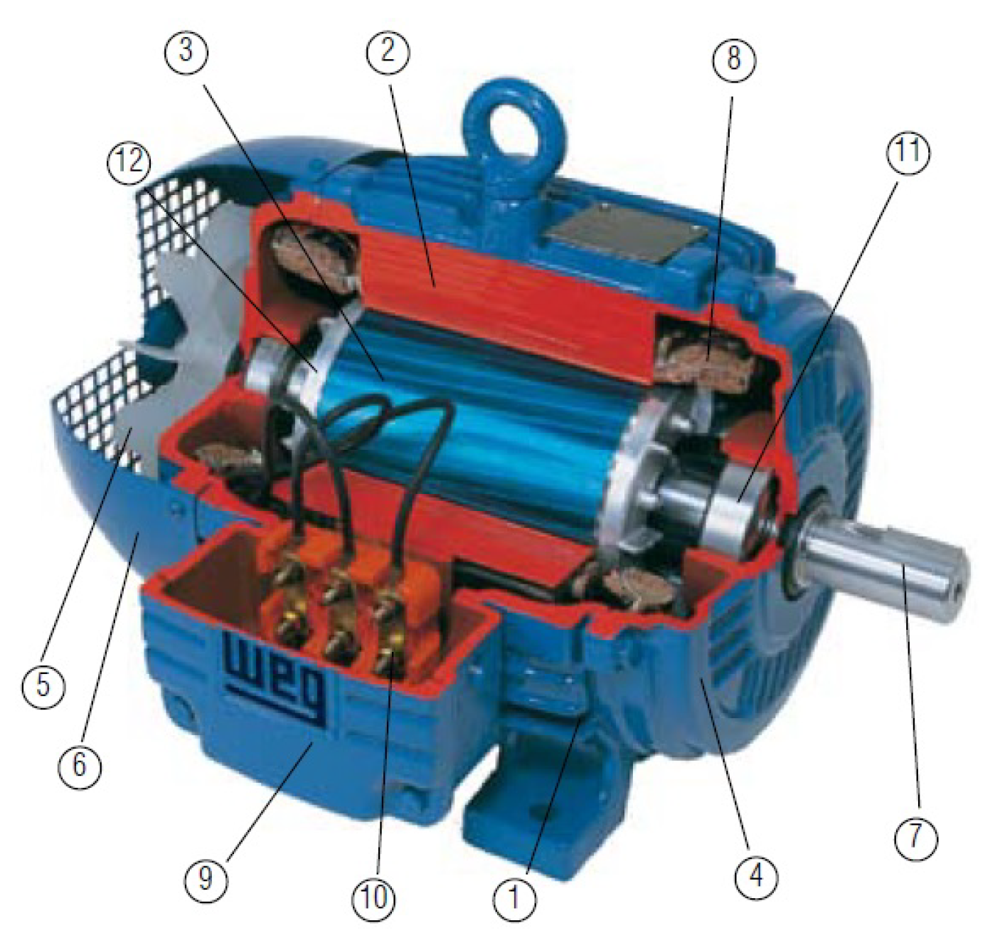
Figure 2.
Failure tree.
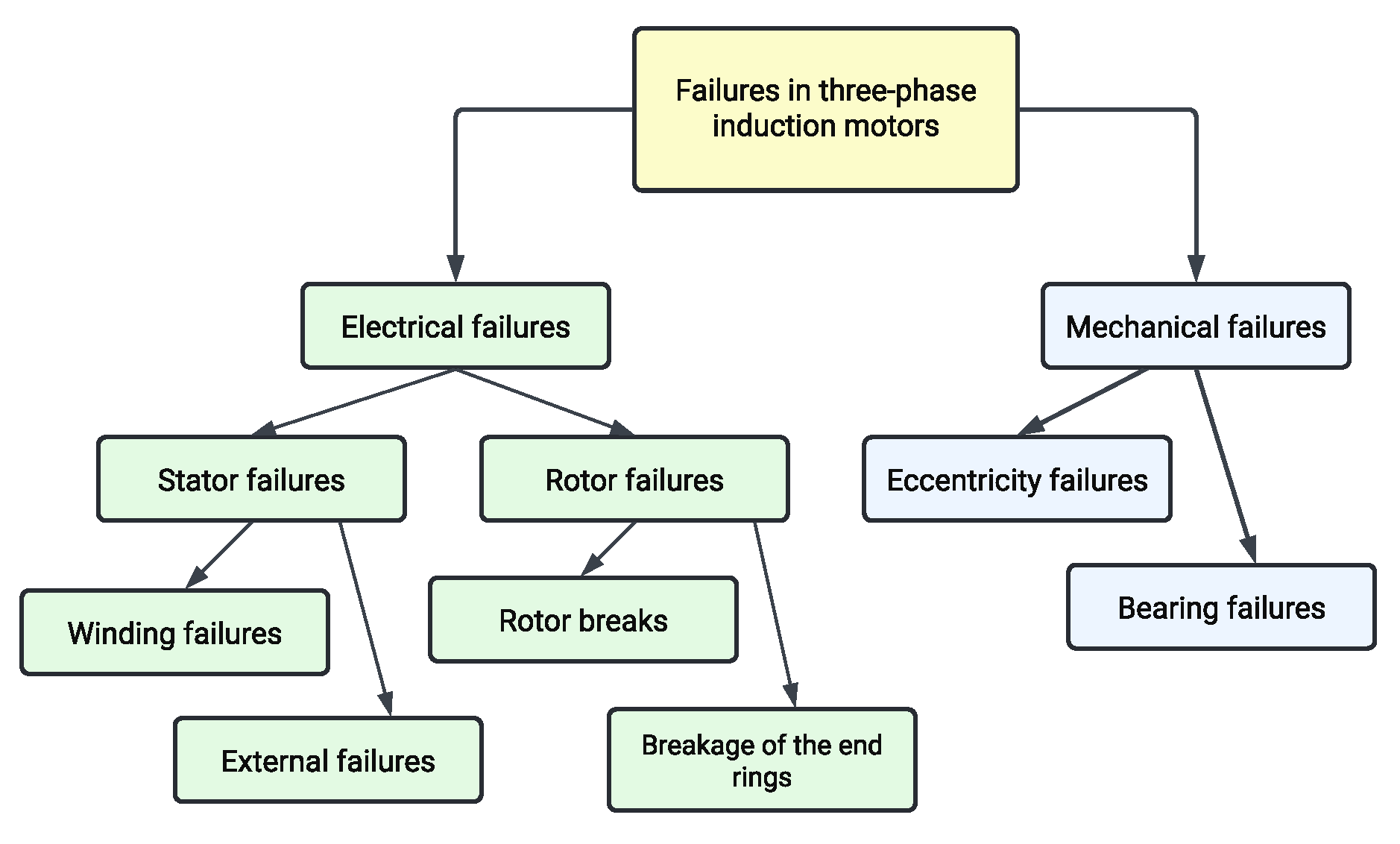
Figure 3.
Topology of a recurrent neural network.
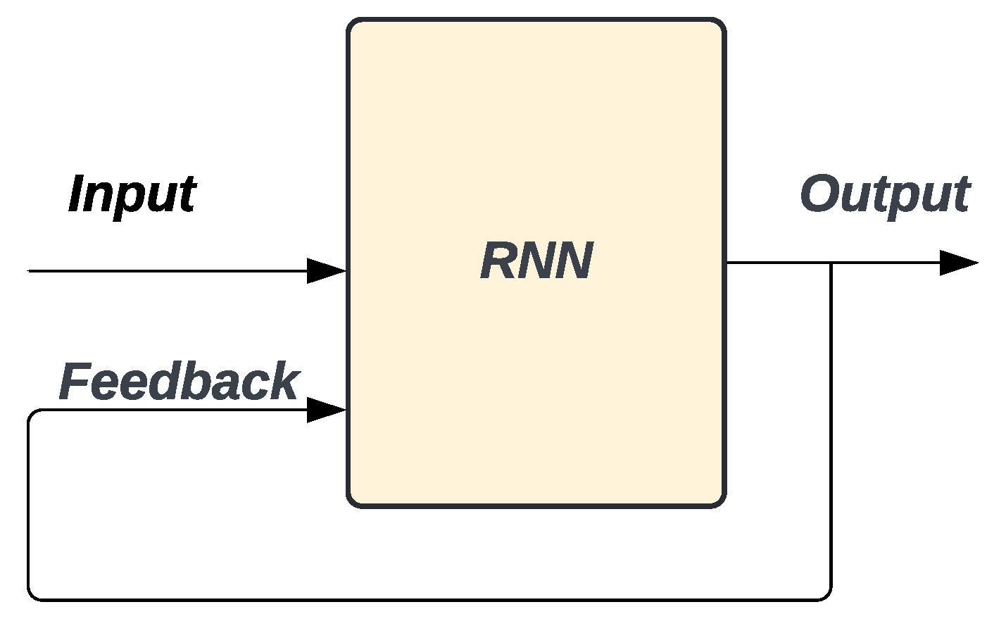
Figure 4.
Topology of a NARX neural network.
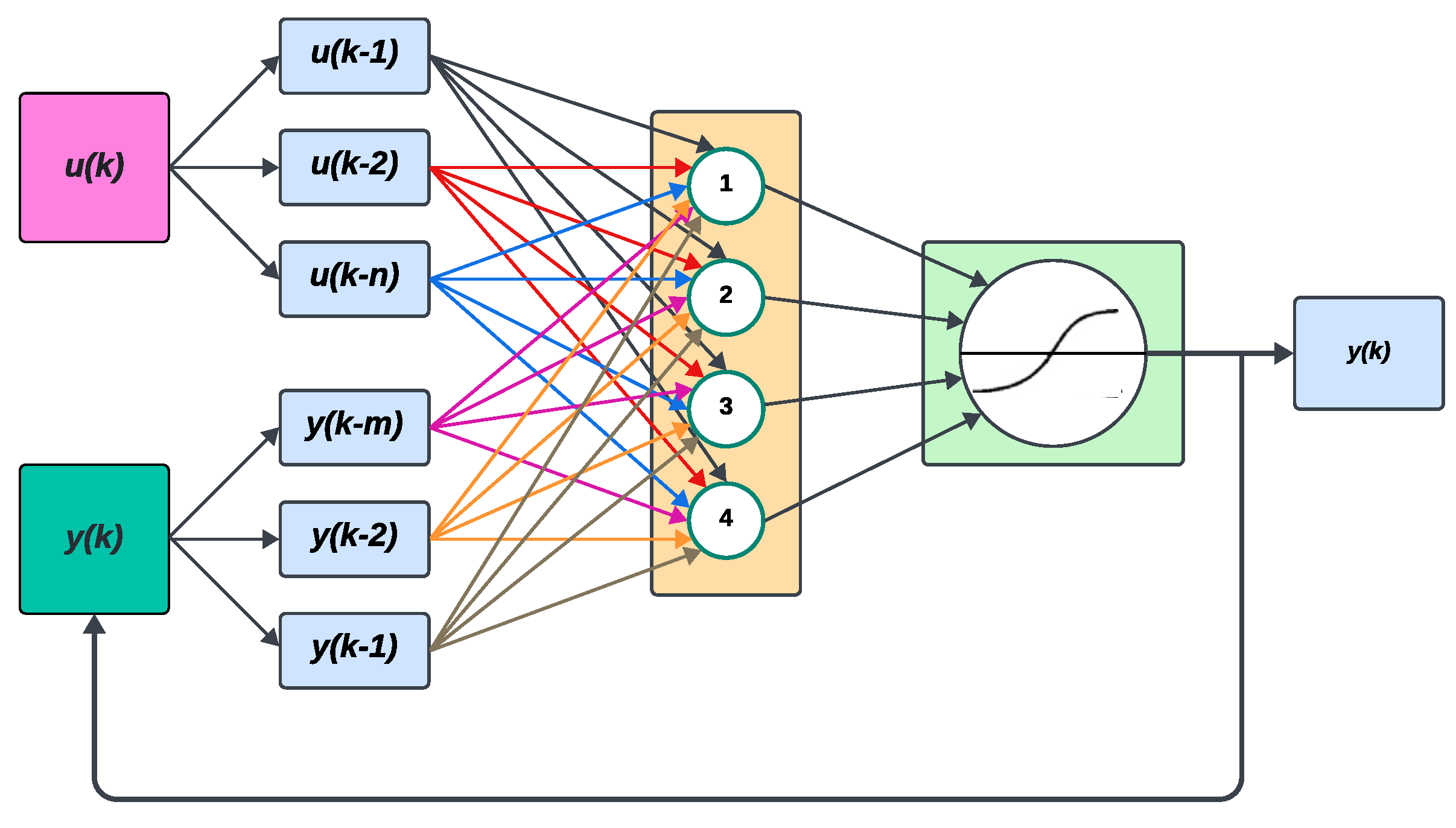
Figure 5.
ROC curve.
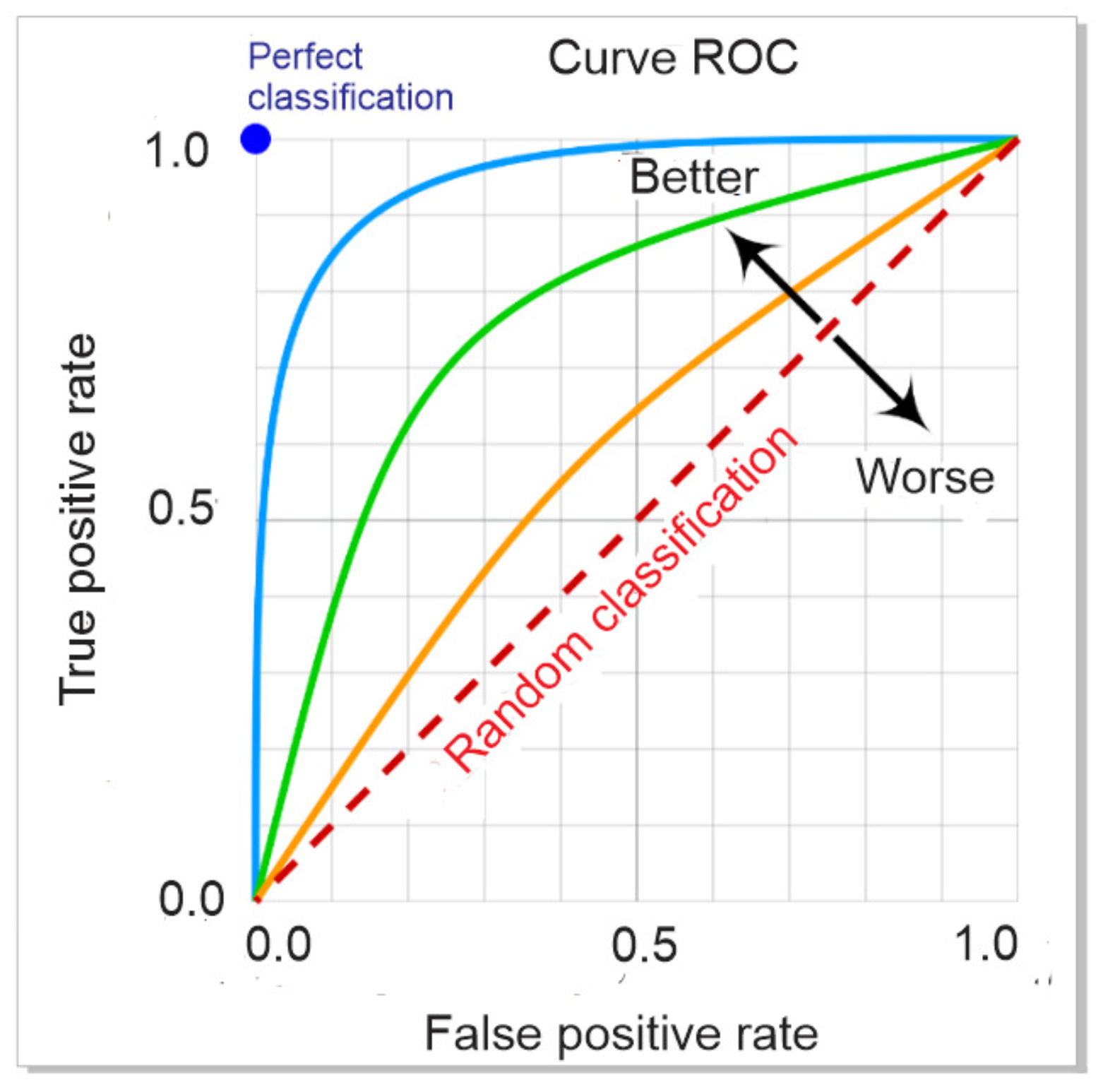
Figure 6.
Confusion matrix for multiclass classification.
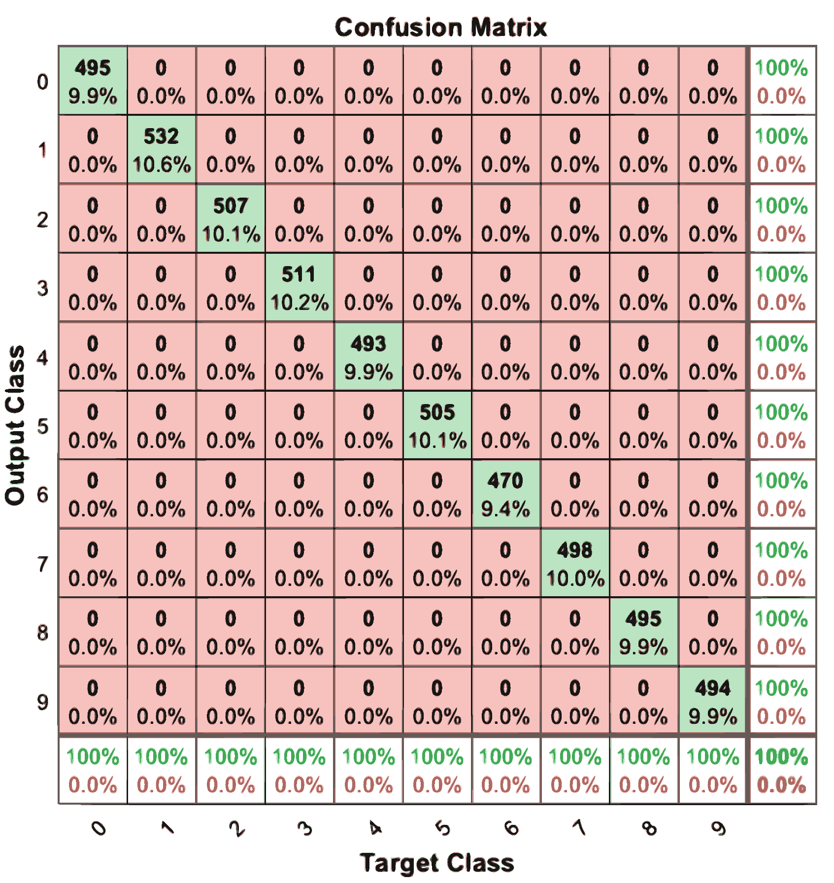
Figure 8.
Test bench.
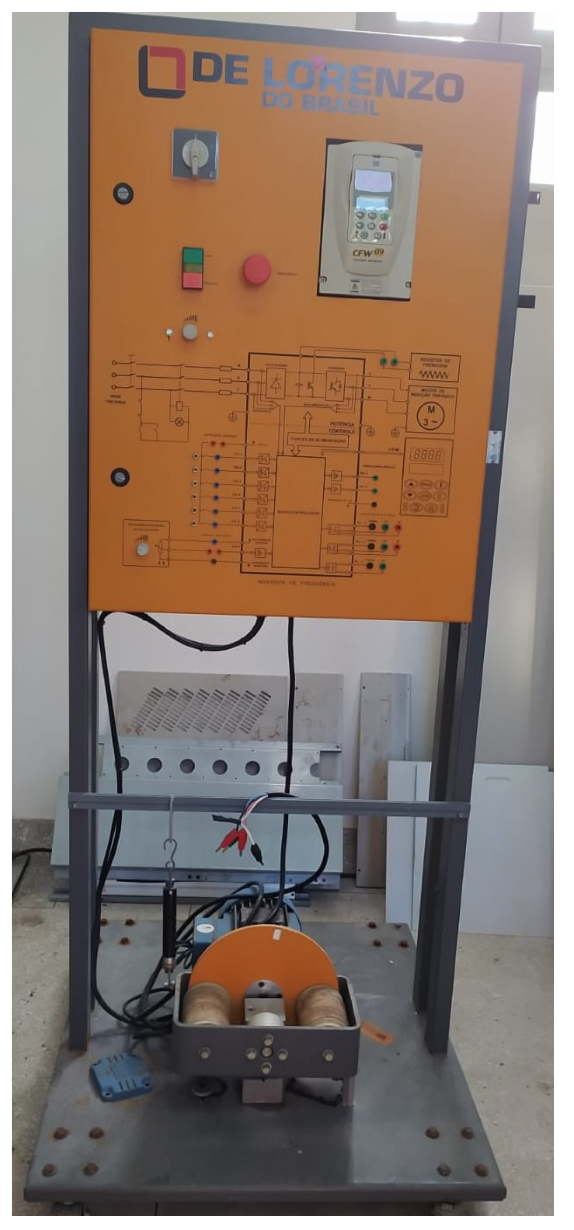
Figure 9.
Three-phase induction motor.
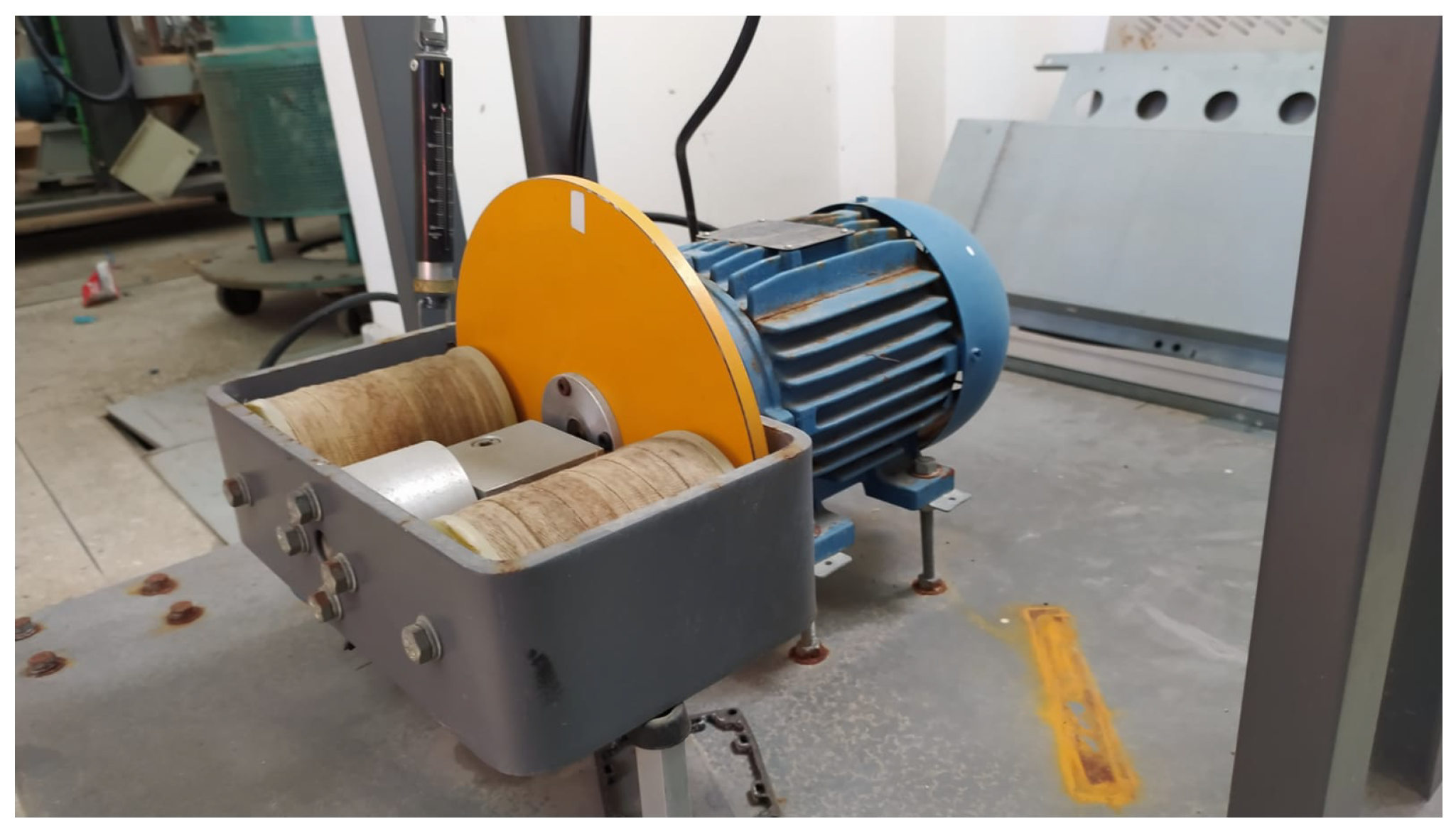
Figure 10.
Current sensor.
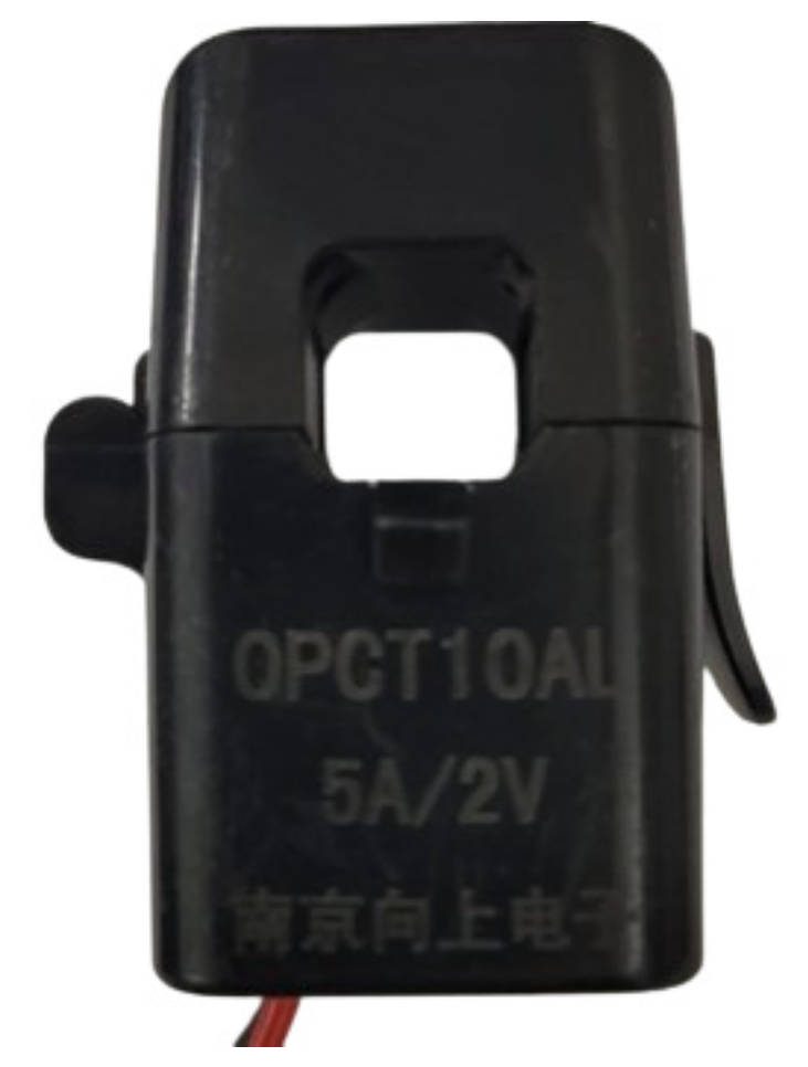
Figure 11.
Signal at the output of the sensor.
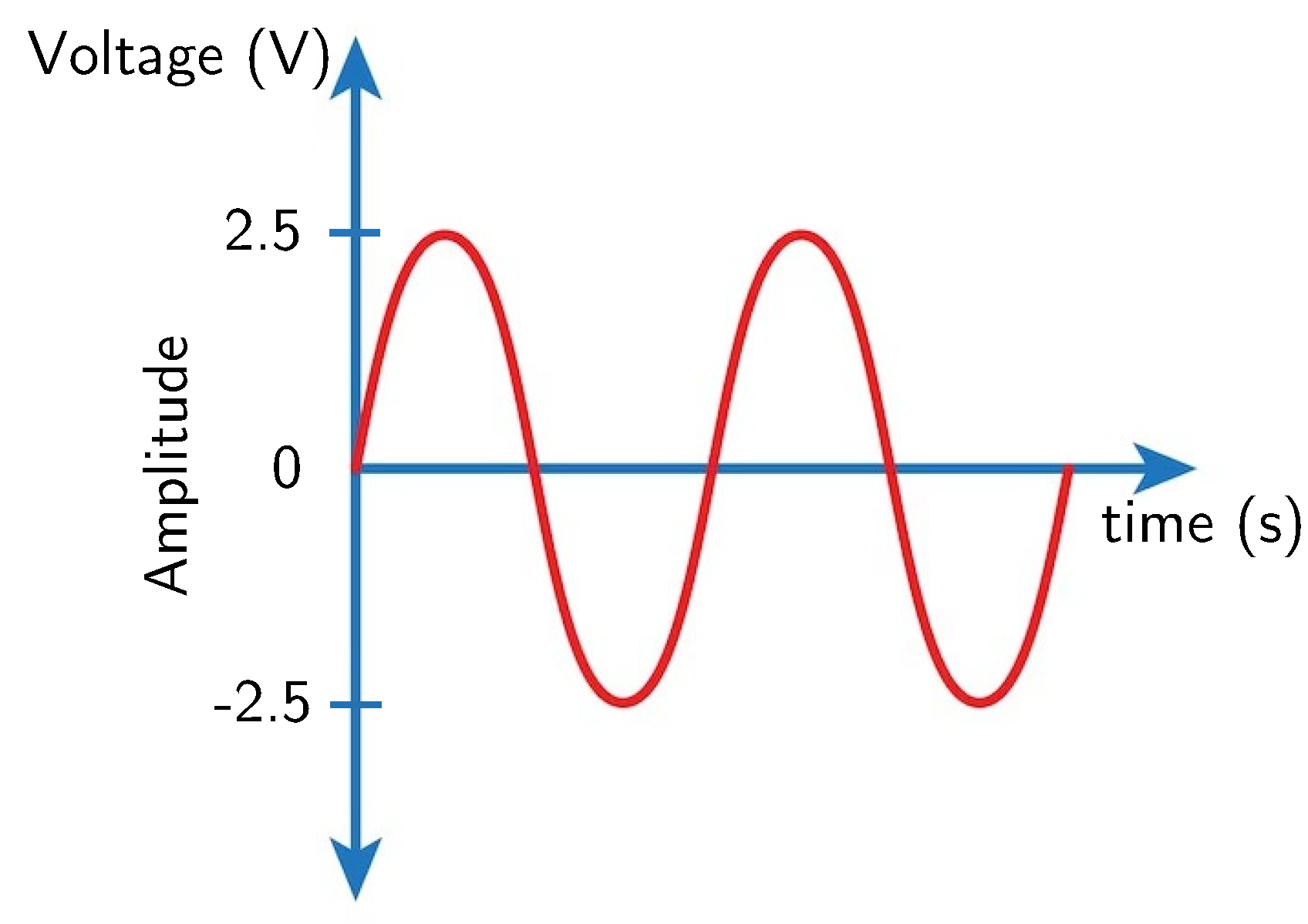
Figure 12.
Current conditioning circuit.
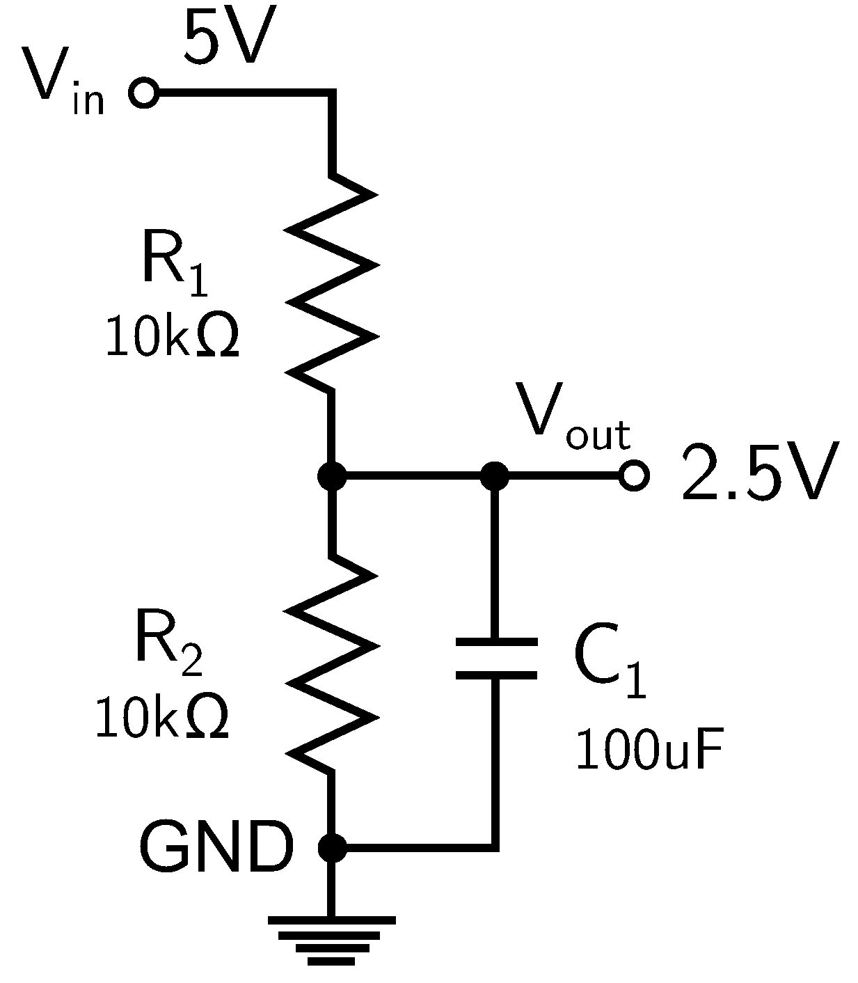
Figure 13.
Current conditioning board.
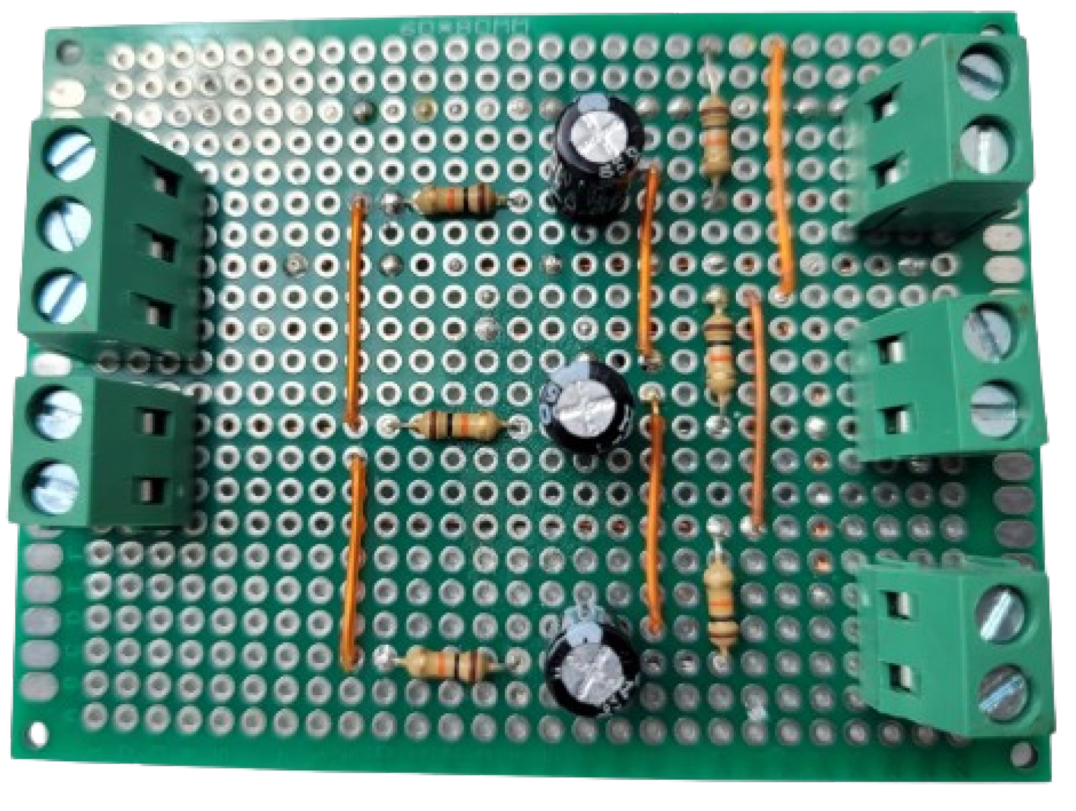
Figure 14.
Sinusoidal waveform with offset value.
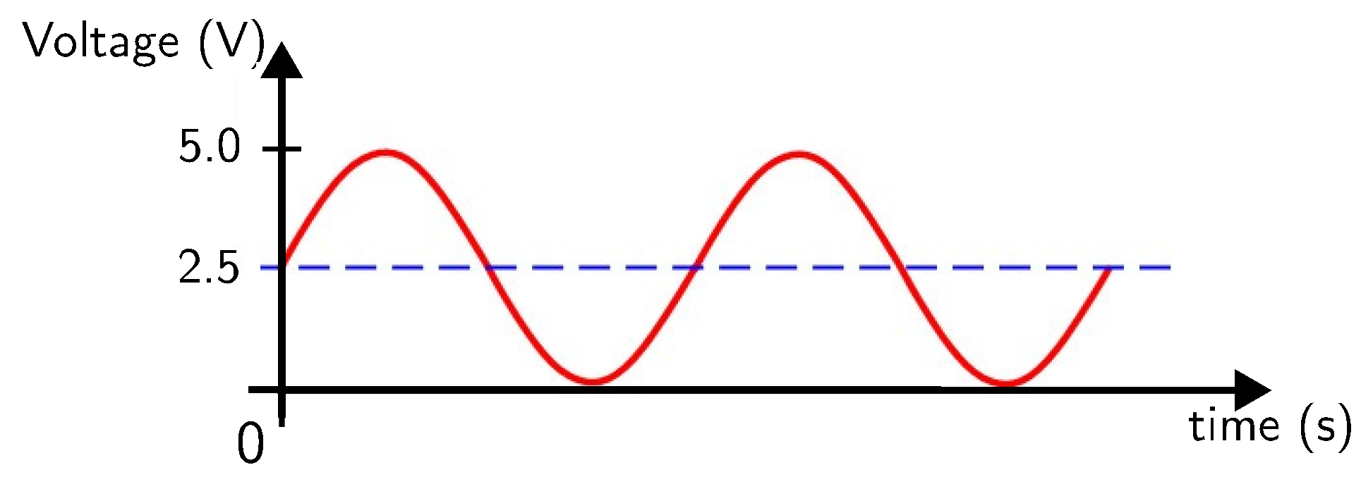
Figure 15.
Vibration accelerometer sensor.
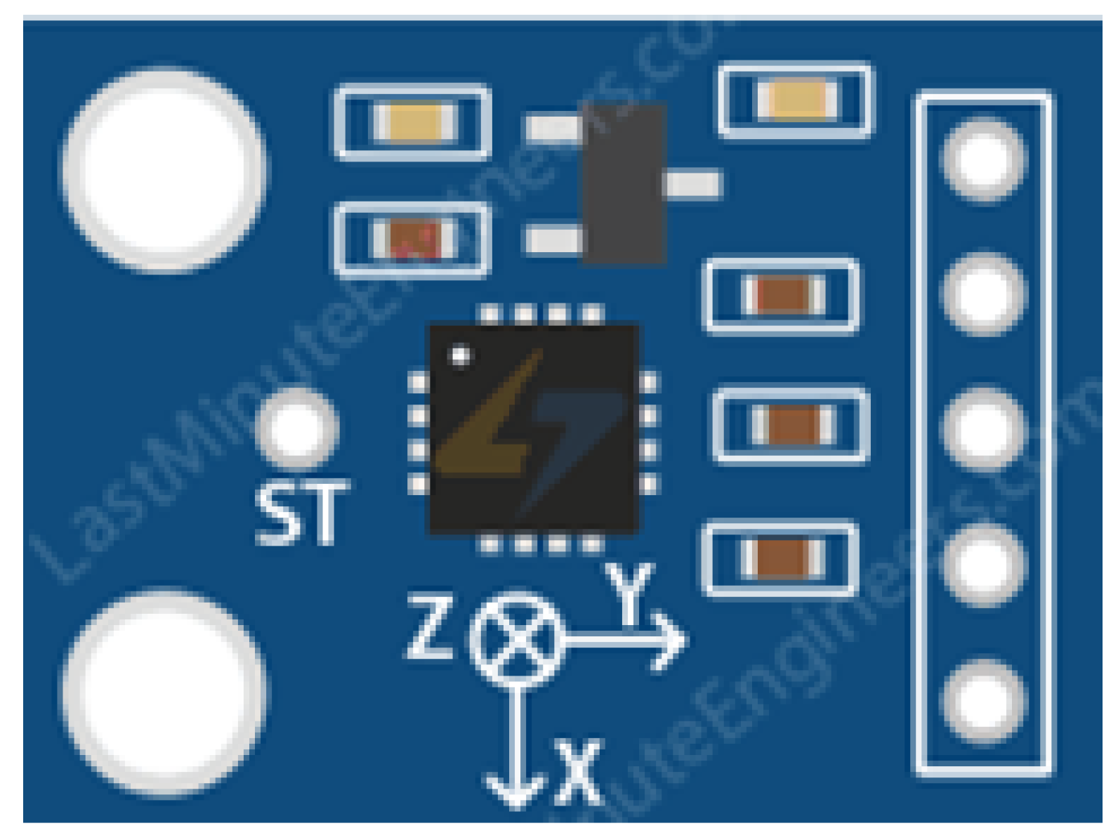
Figure 16.
Temperature sensor.
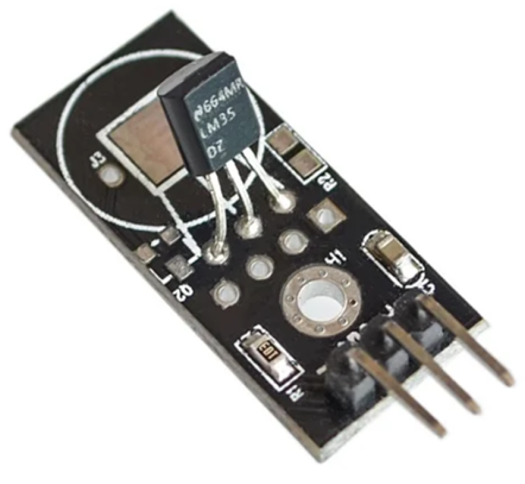
Figure 17.
NI USB 6008.
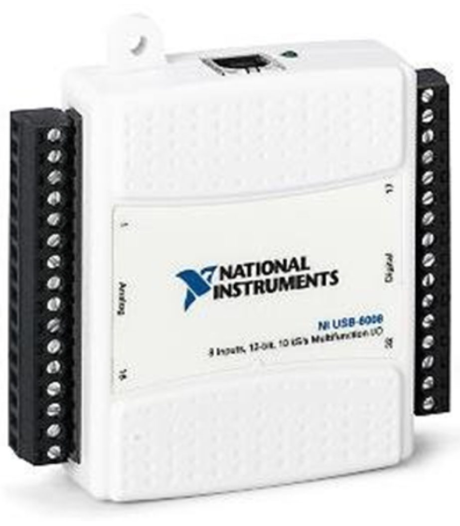
Figure 18.
LabVIEW block diagram.
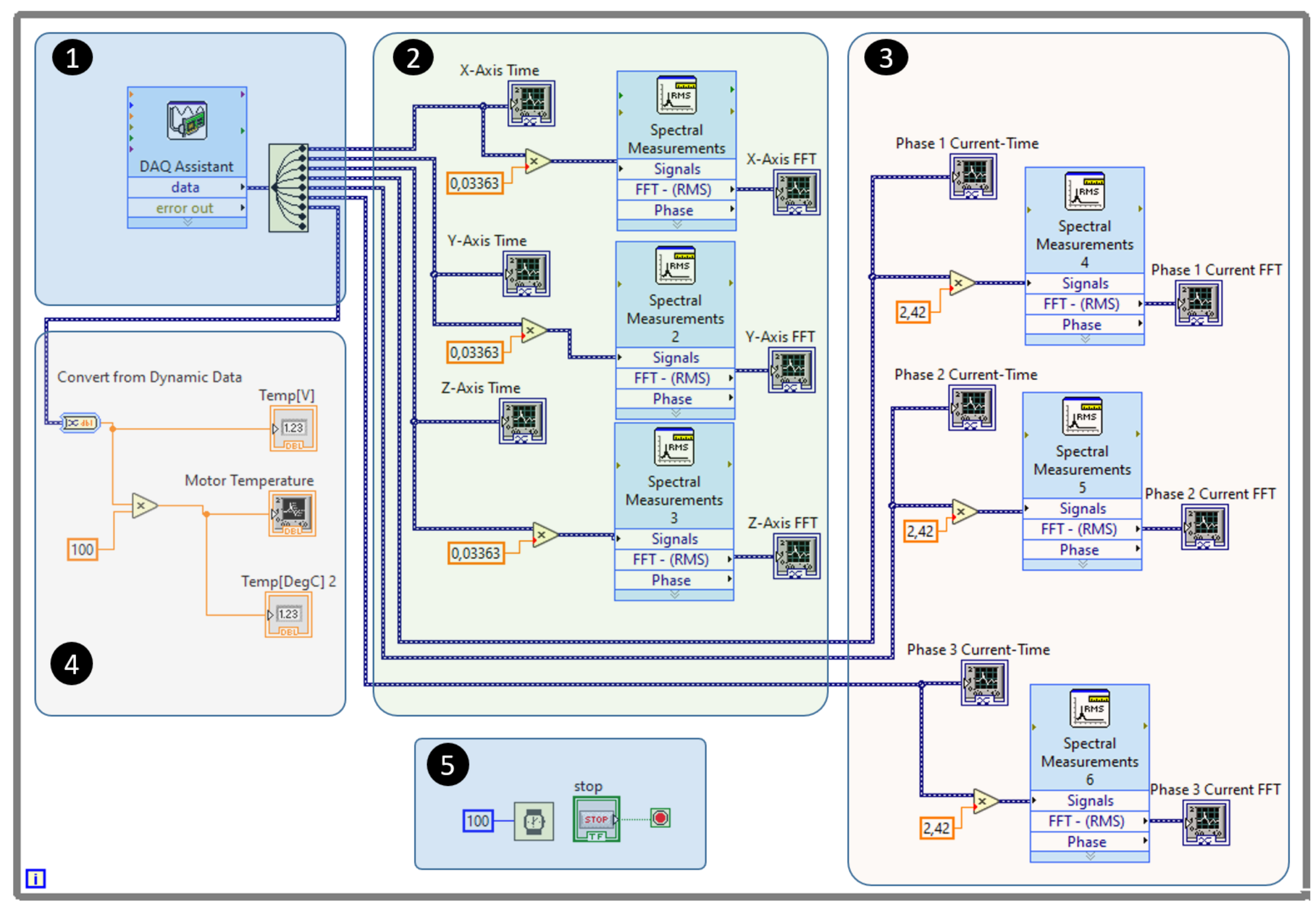
Figure 19.
NARX neural network.

Figure 20.
Sensors installed in the motor.
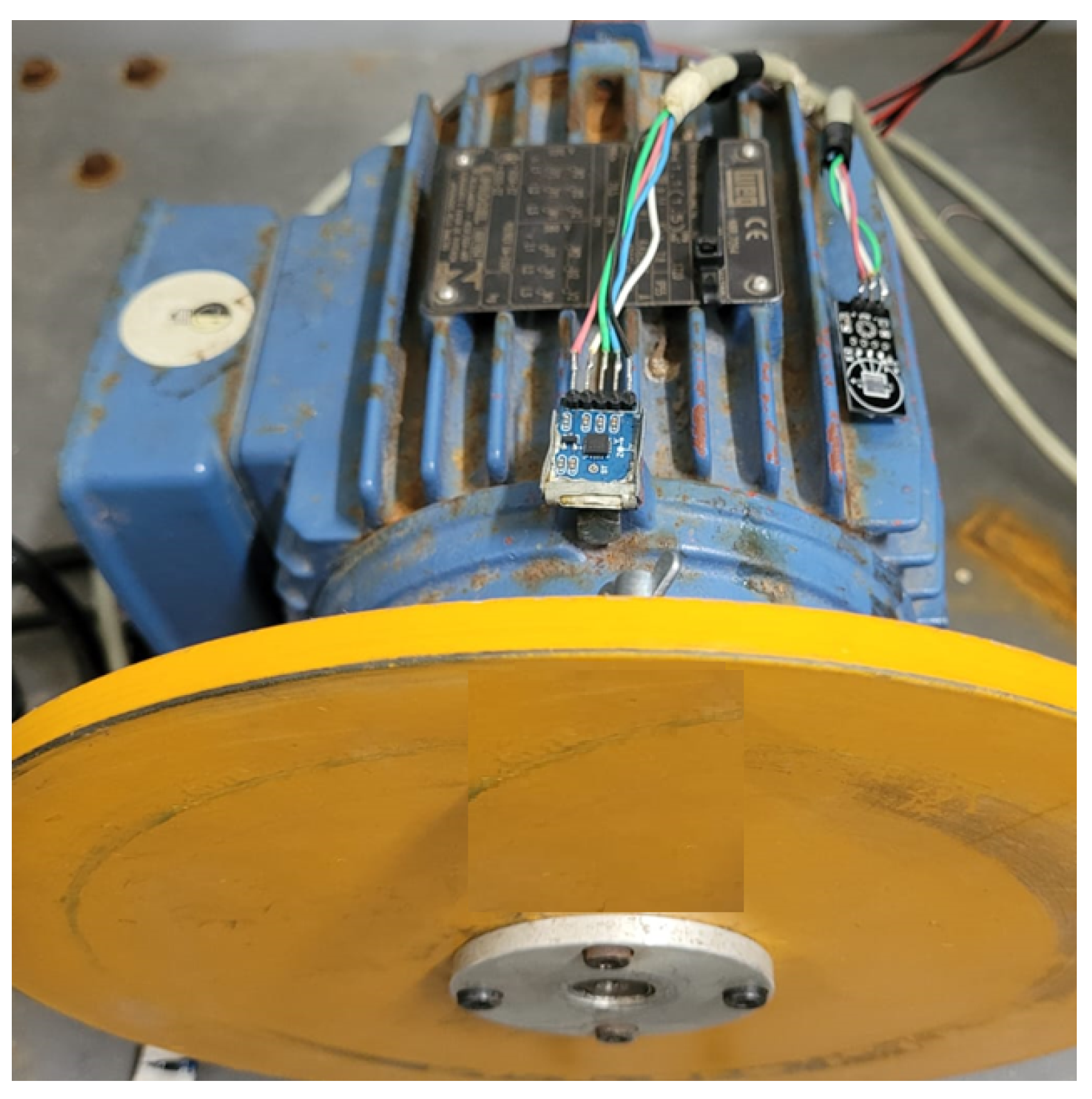
Figure 21.
Vibration signal in the time domain.
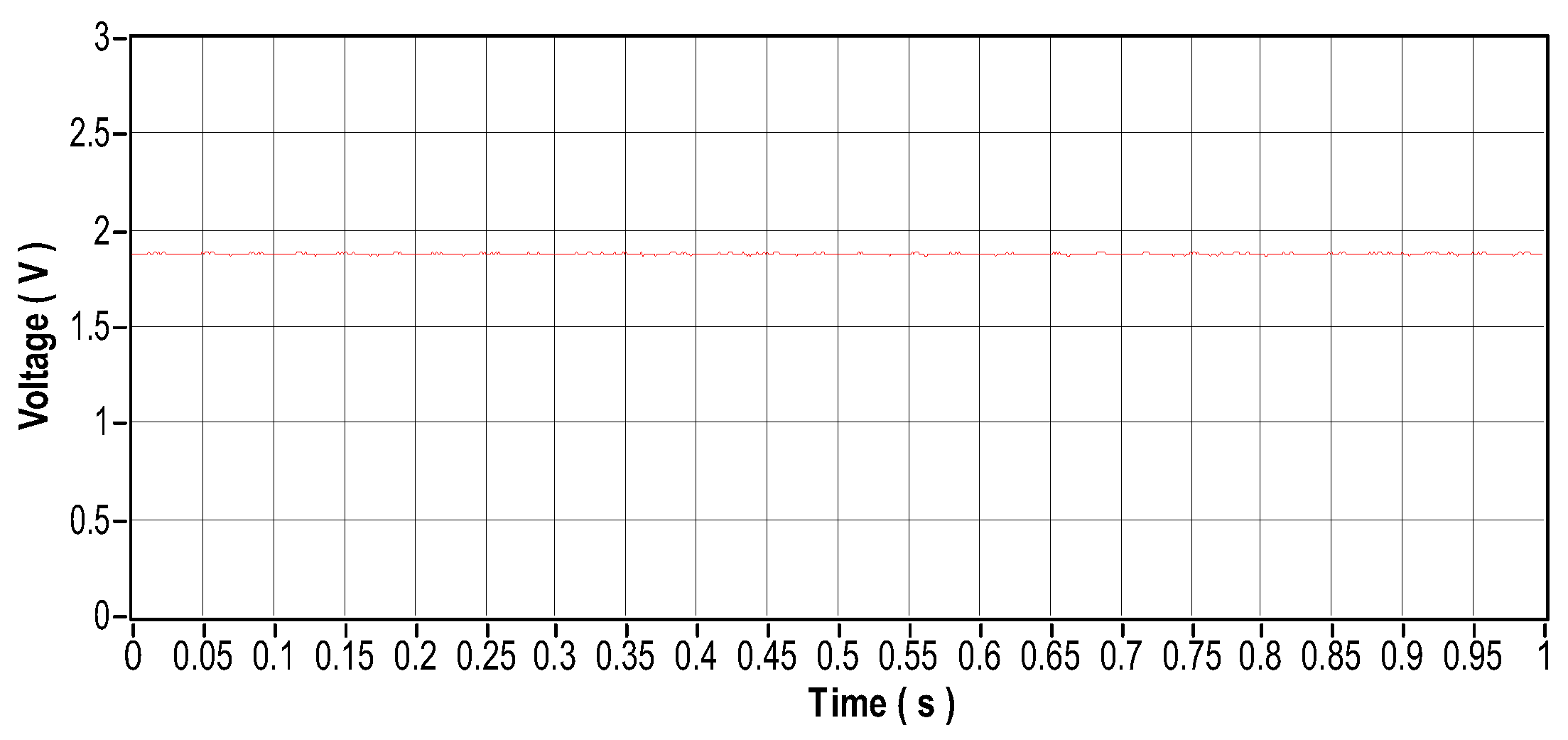
Figure 22.
Vibration signal in the frequency domain.
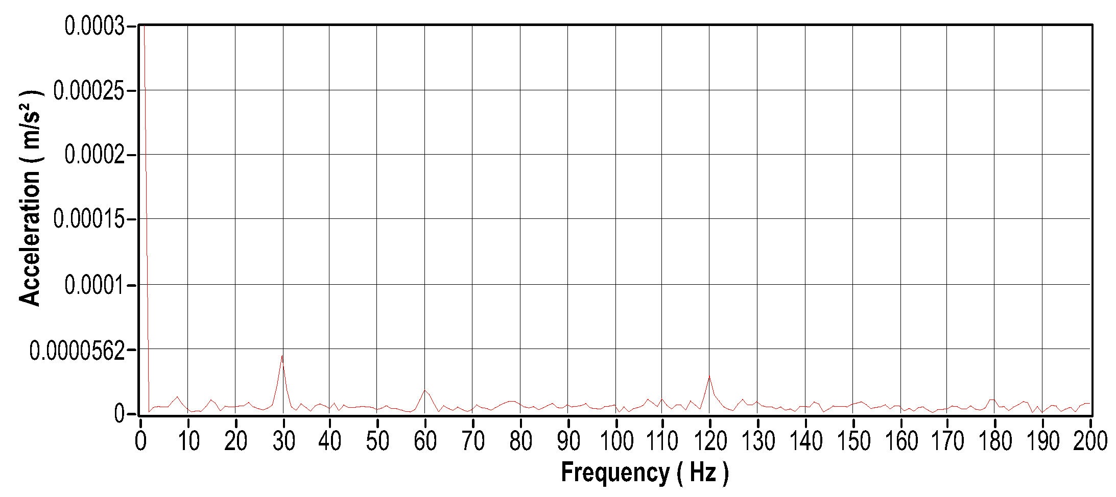
Figure 23.
Current signal in the time domain.
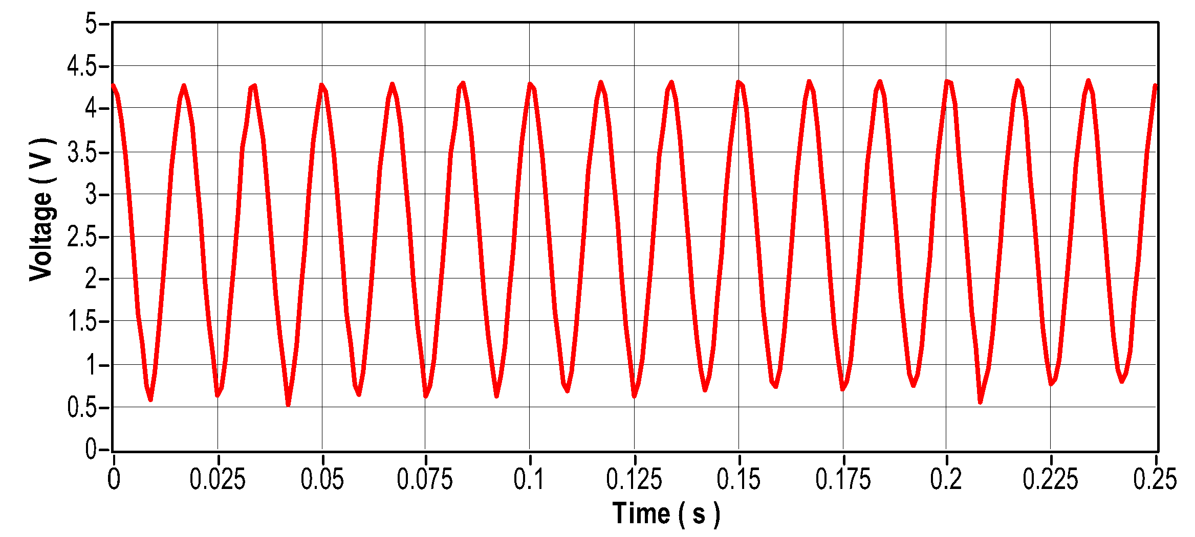
Figure 24.
Current signal in the frequency domain.
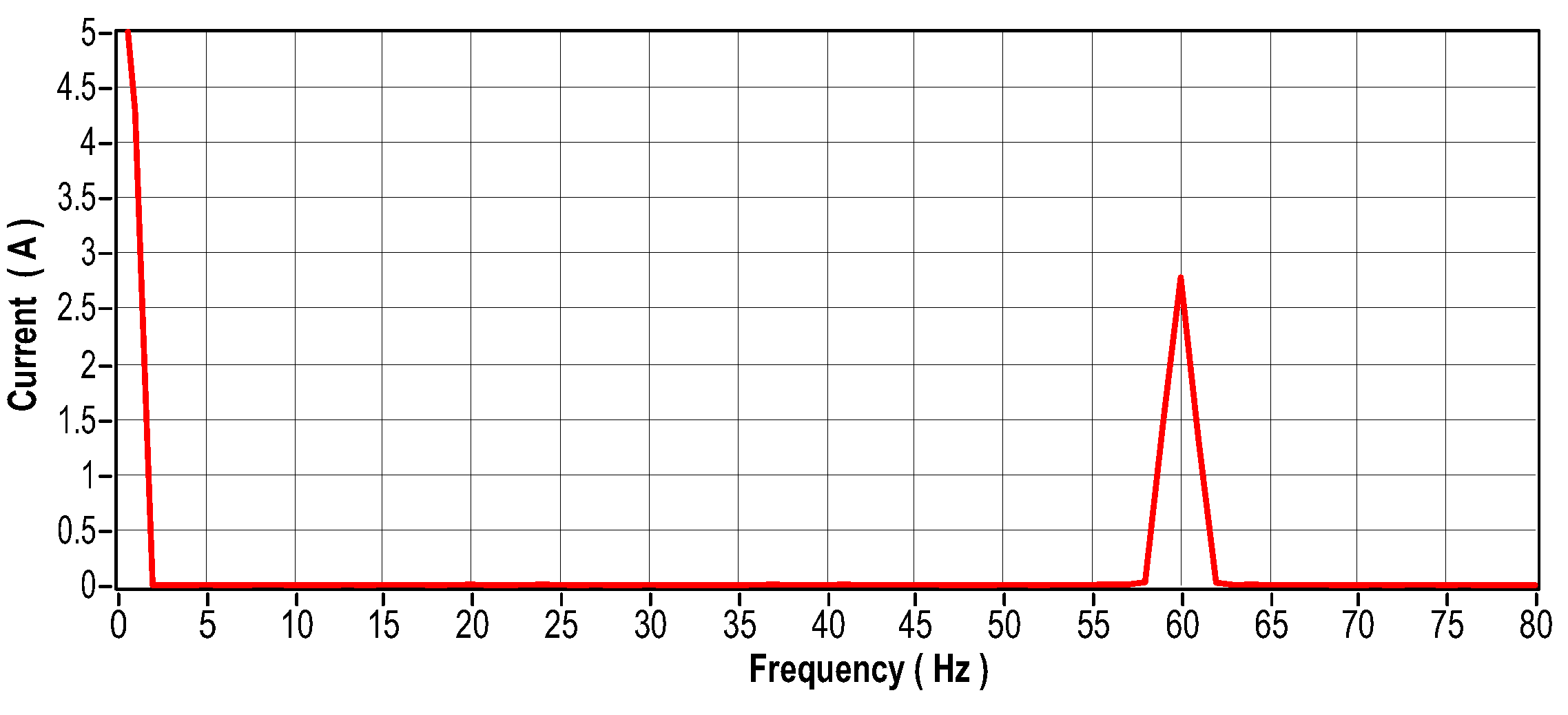
Figure 25.
Signal of motor temperature under good operating conditions.
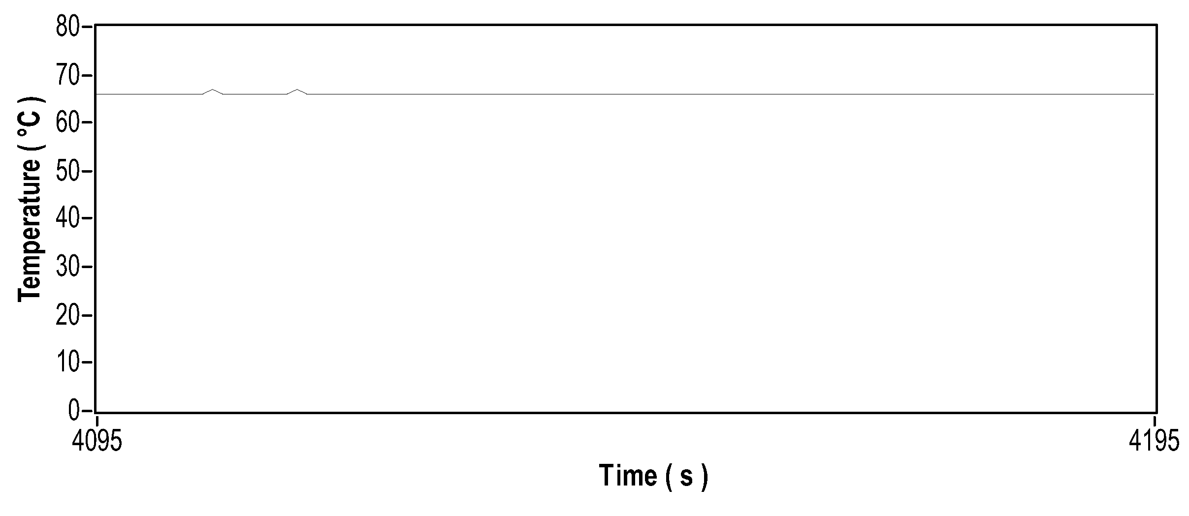
Figure 26.
Installation of mass for unbalancing.
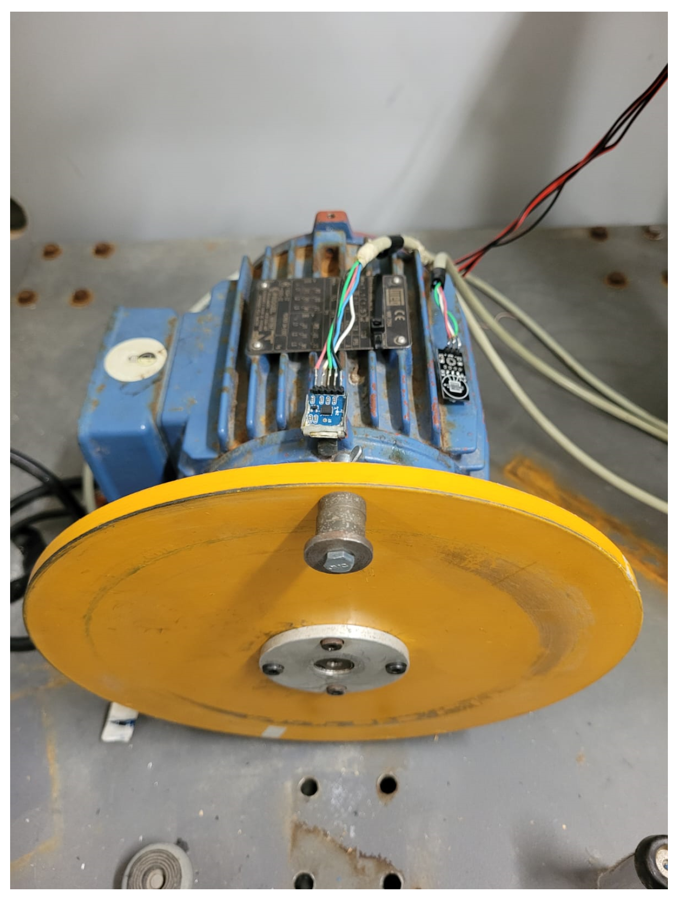
Figure 27.
Vibration signal in the time domain.
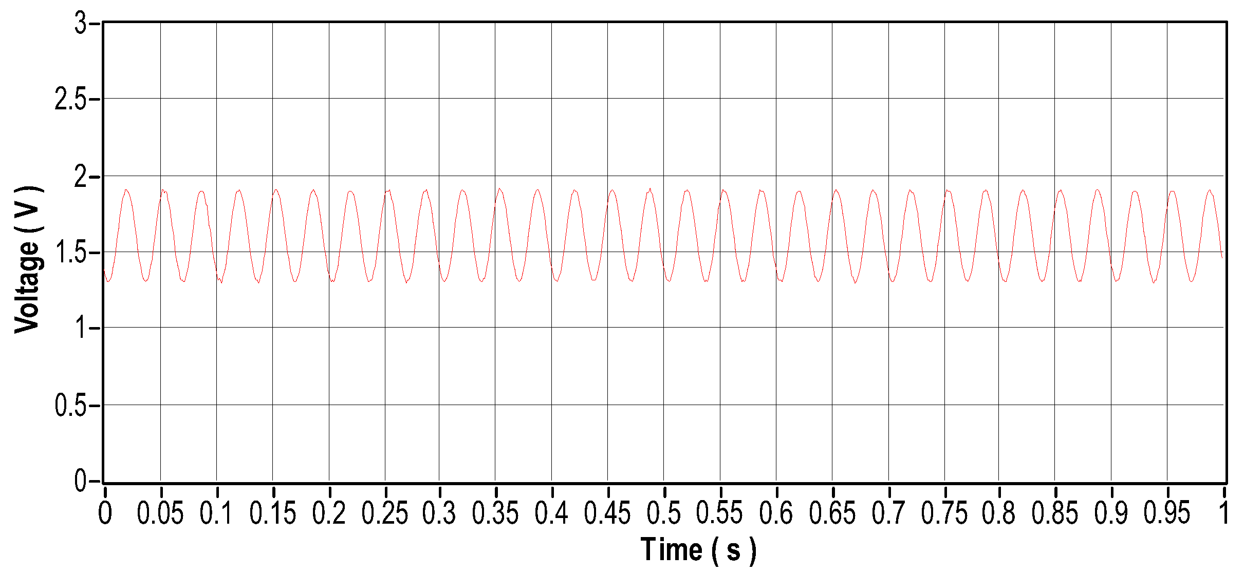
Figure 28.
Vibration signal in the frequency domain.
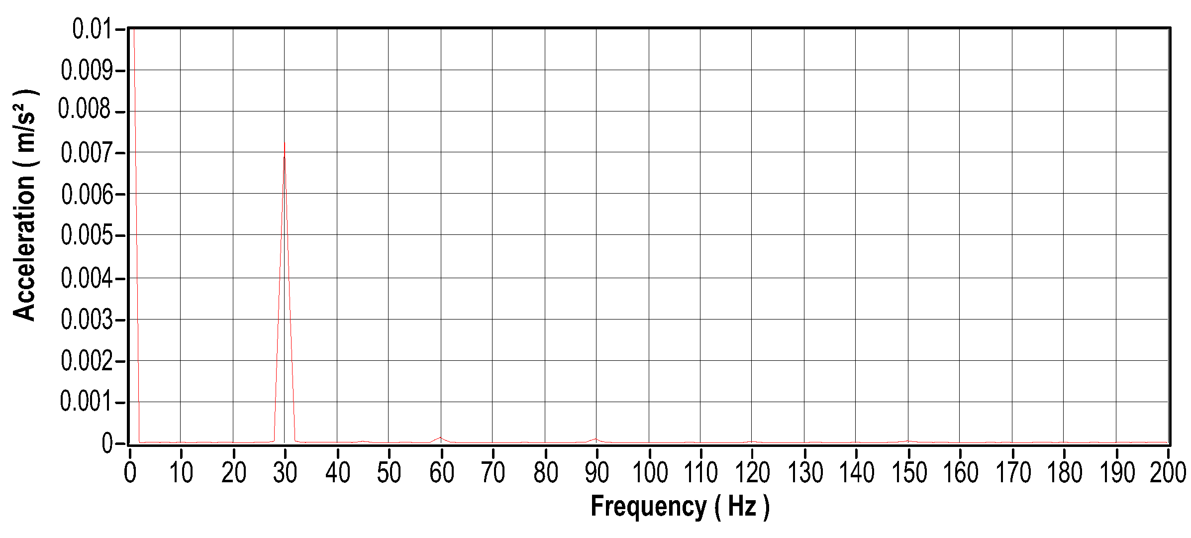
Figure 29.
Current signal in the time domain.
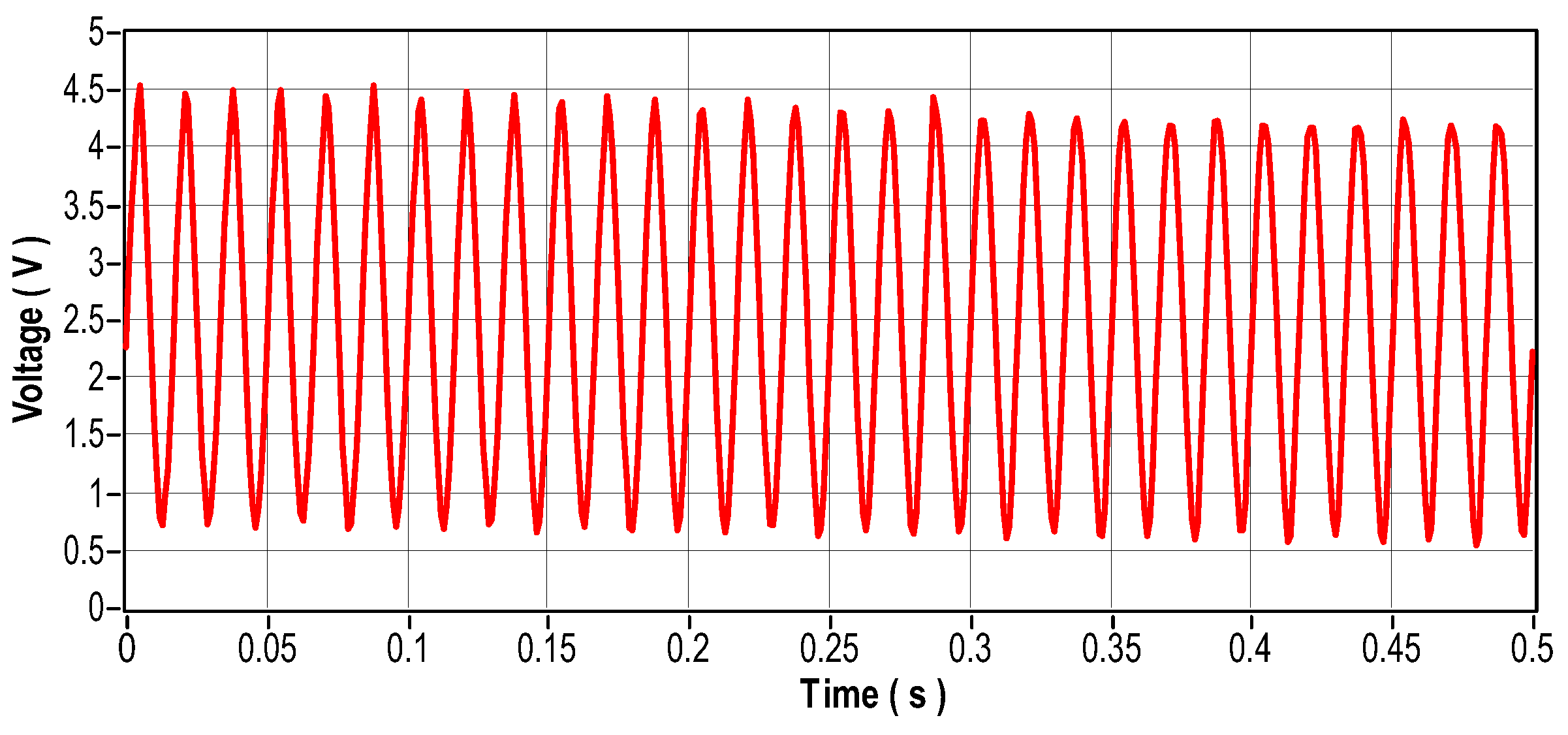
Figure 30.
Current signal in the frequency domain.
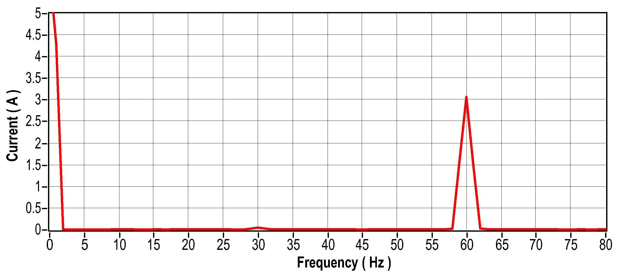
Figure 31.
Temperature signal for unbalanced motor.
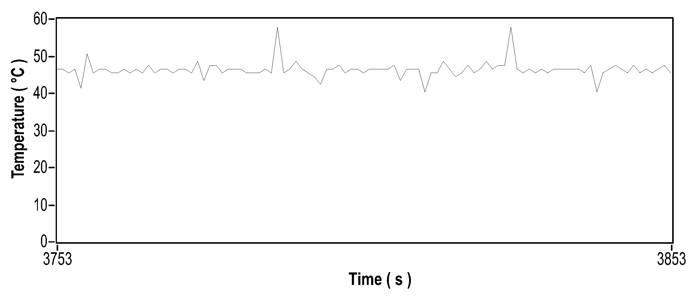
Figure 50.
Standard training ROC curve.
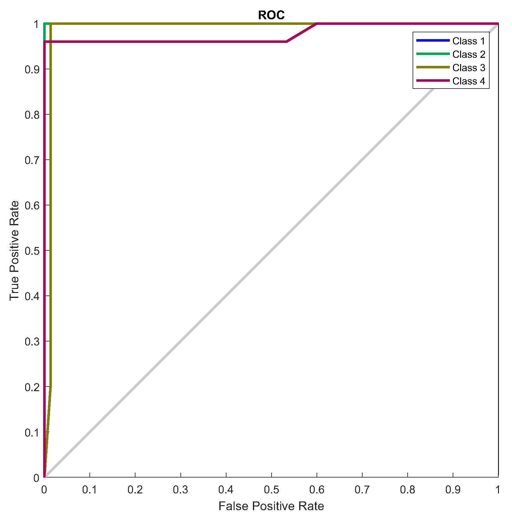
Figure 51.
Standard training confusion matrix.
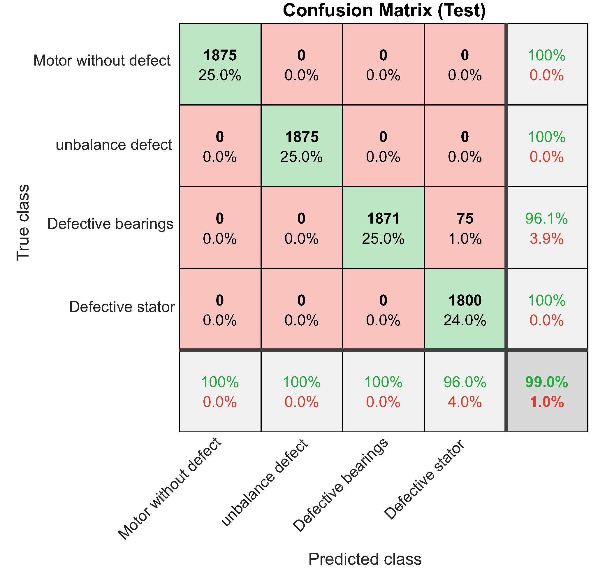
Figure 52.
Failures classified in standard training.
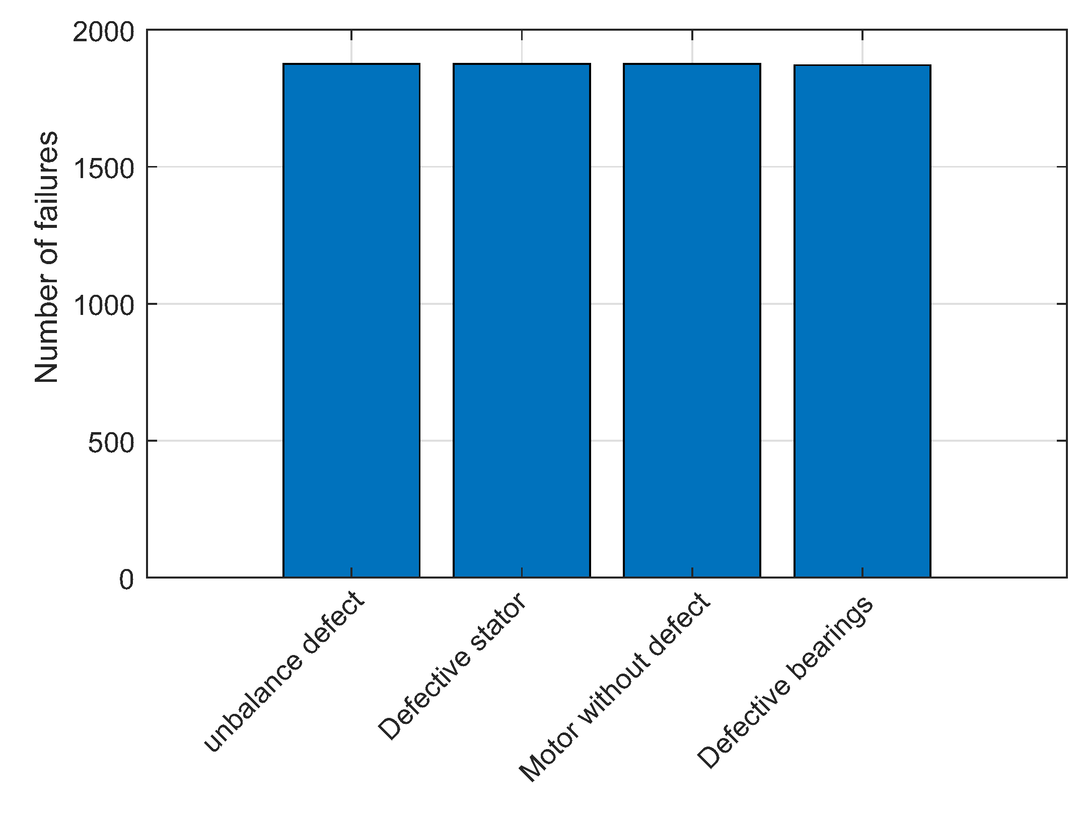
Figure 53.
ROC curve of the Motor without defect test set.
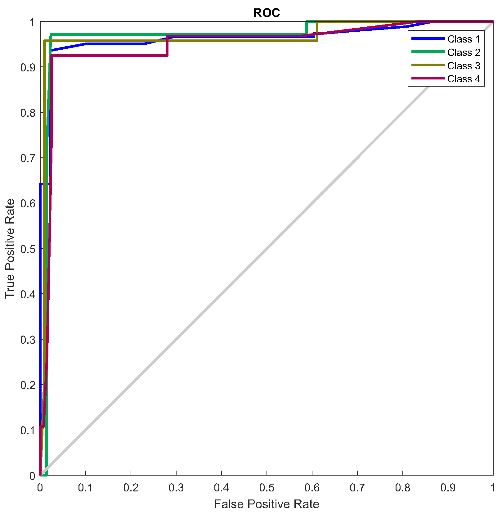
Figure 54.
Confusion matrix of the ’Motor without defect’ test set.
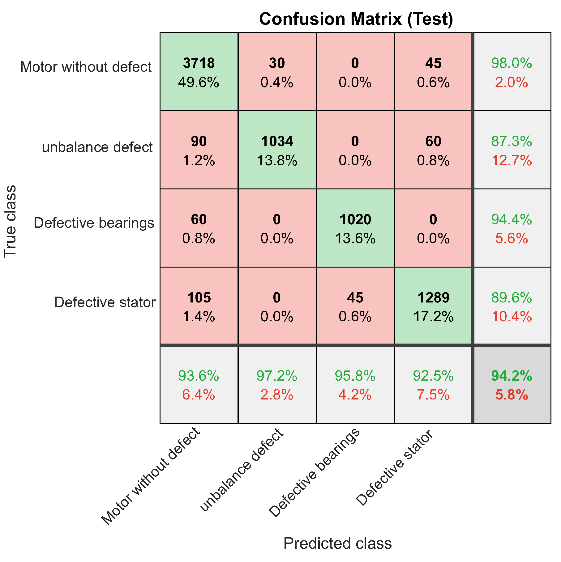
Figure 55.
Number of failures classified in the ’Motor without defect’ test set.
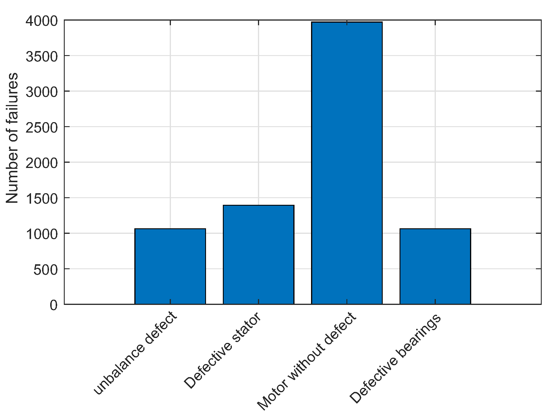
Figure 56.
ROC curve of the Defect unbalance test set.
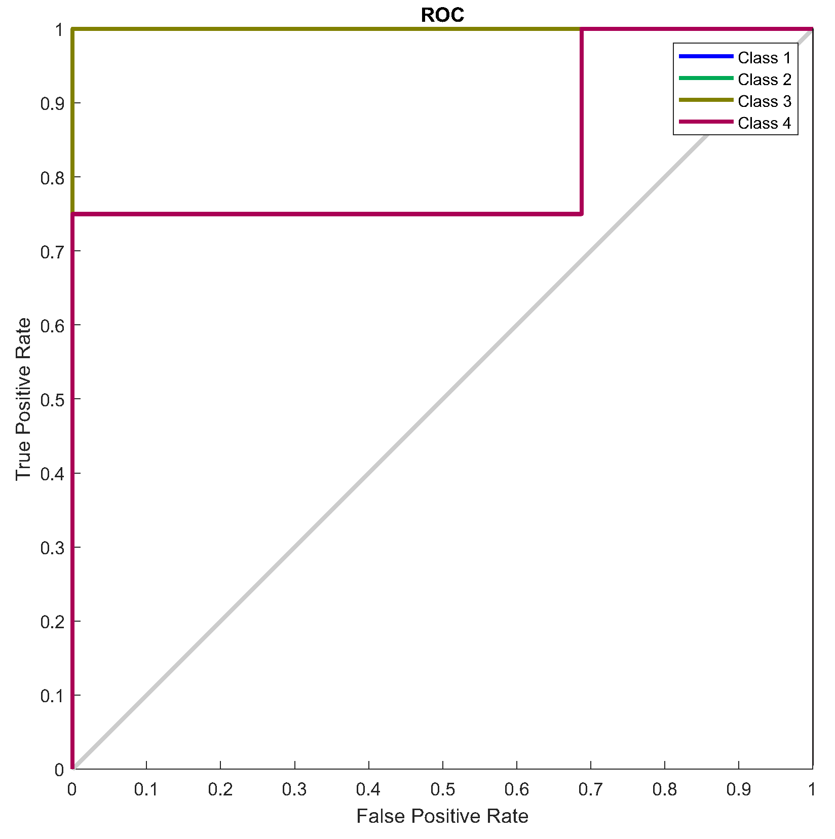
Figure 57.
Confusion matrix of the ’Defect unbalance’ test set.
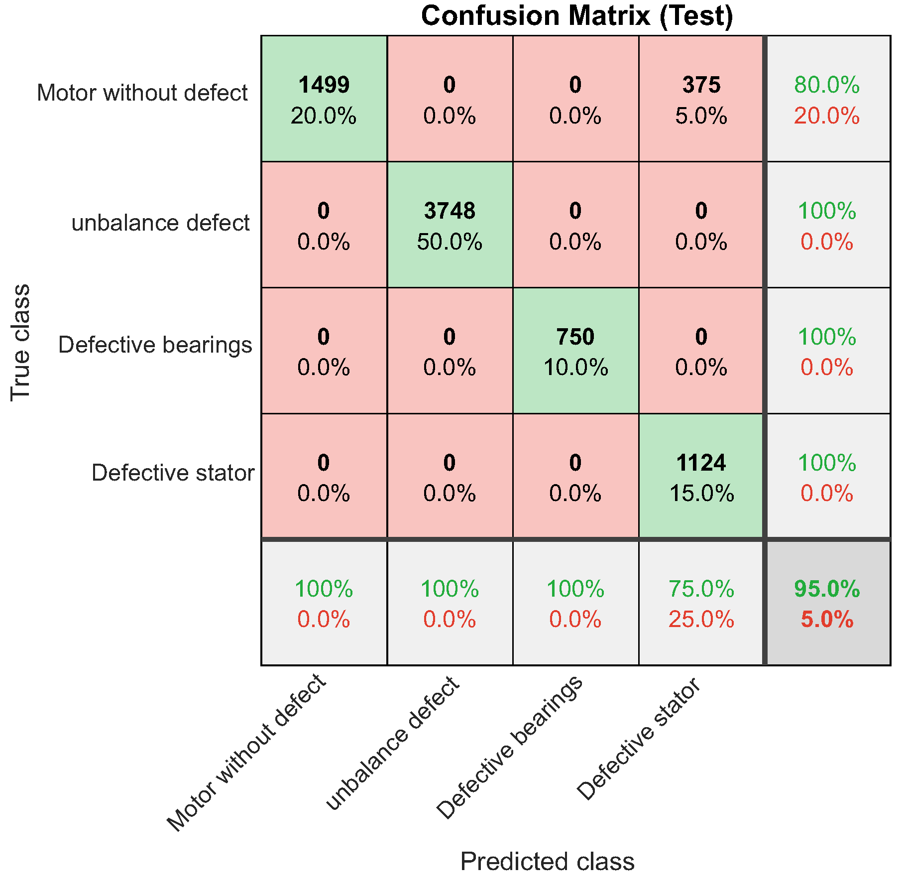
Figure 58.
Number of failures classified in the ’Defect unbalance’ test set.
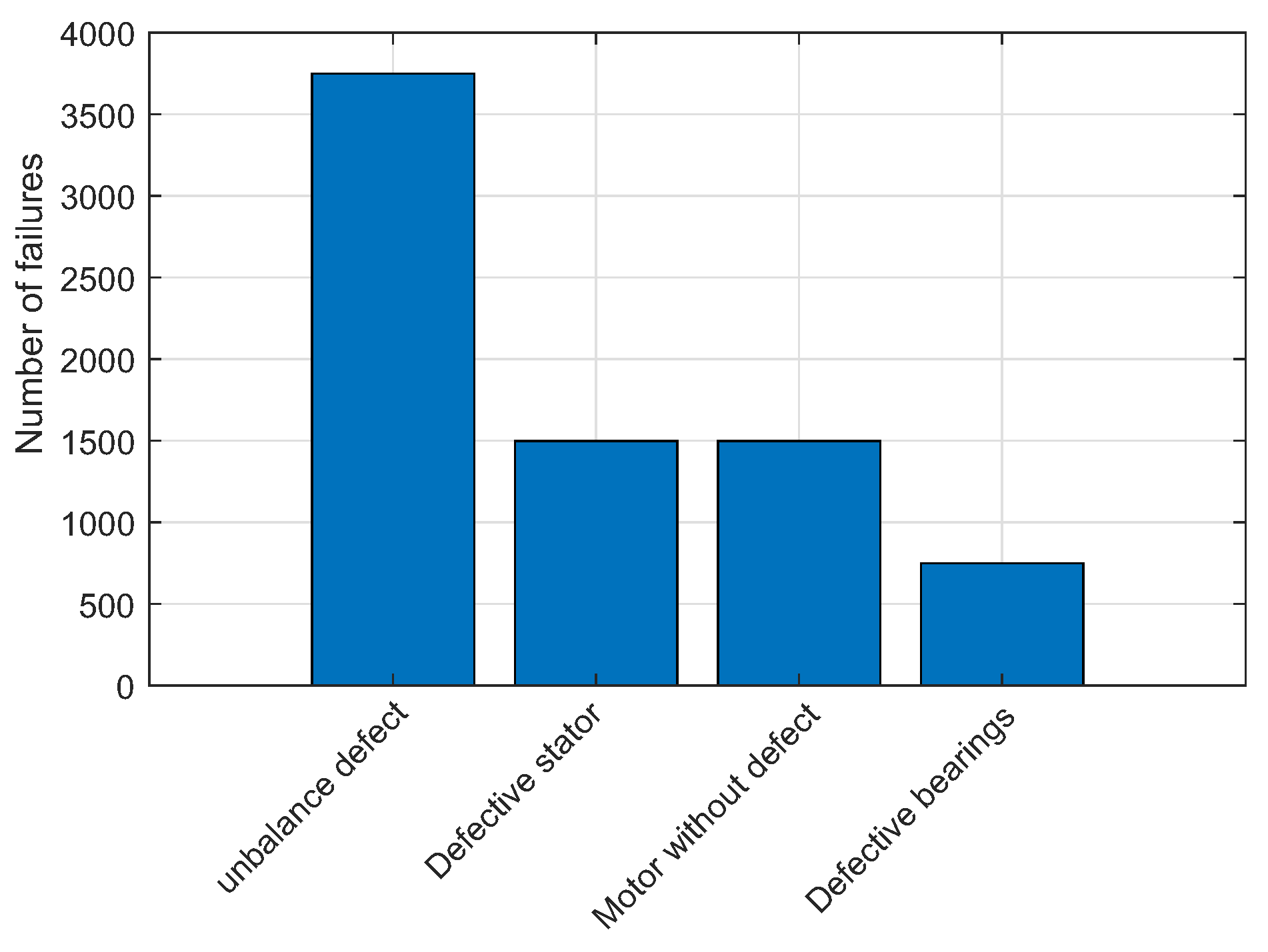
Figure 59.
ROC curve of the Faulty Bearings test set.
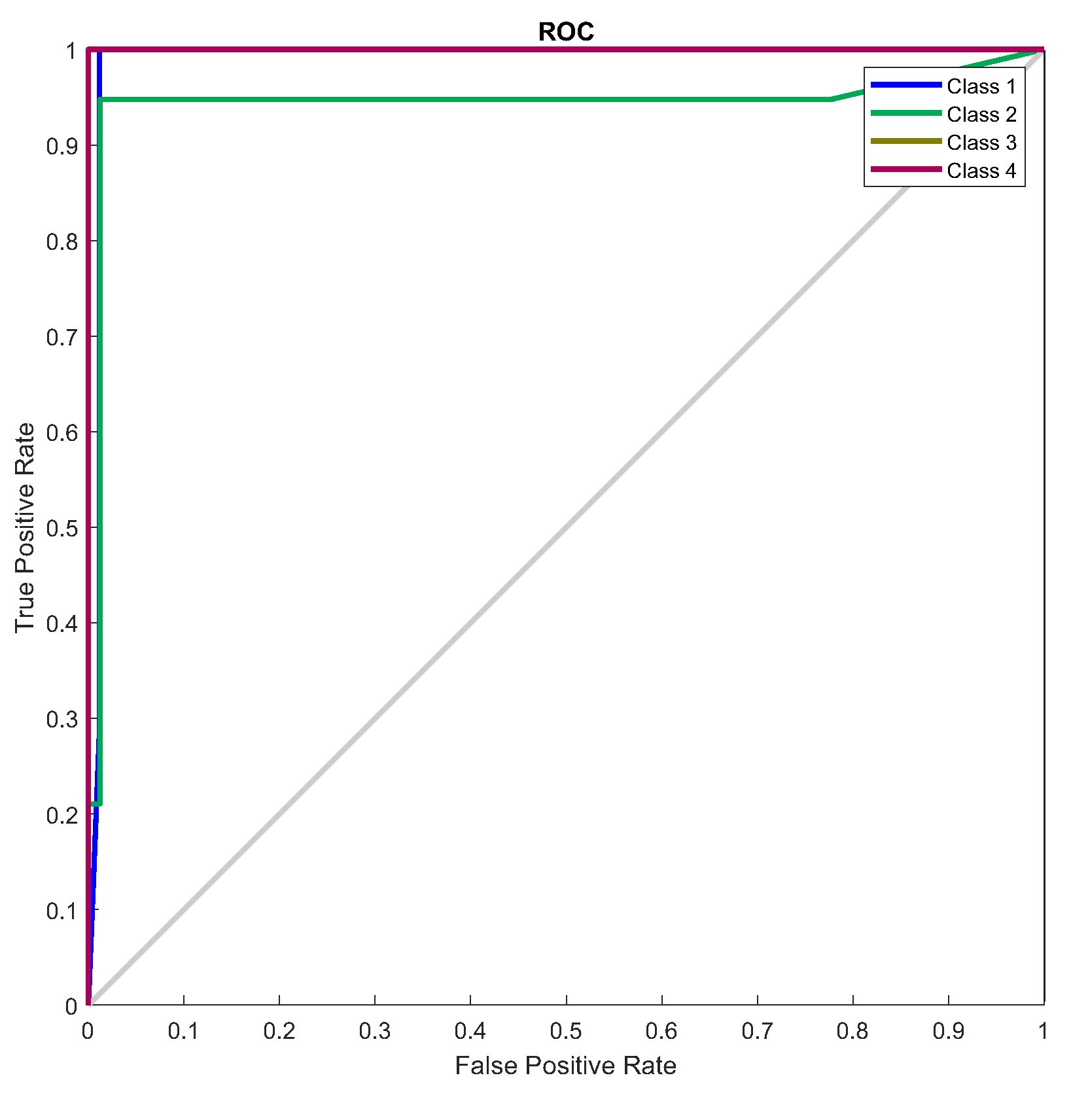
Figure 60.
Confusion matrix for defective bearings.
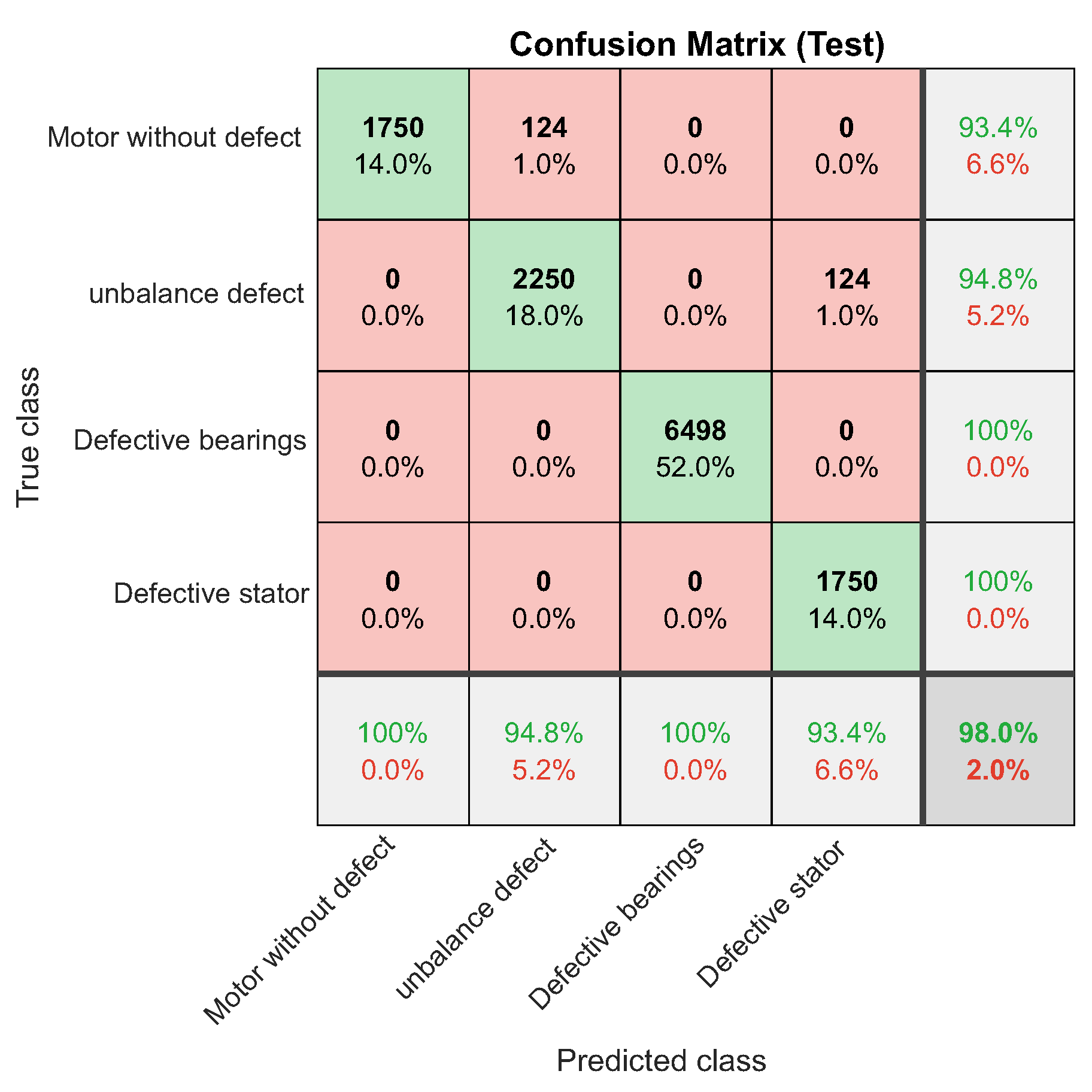
Figure 61.
Classified failures for defective bearings.
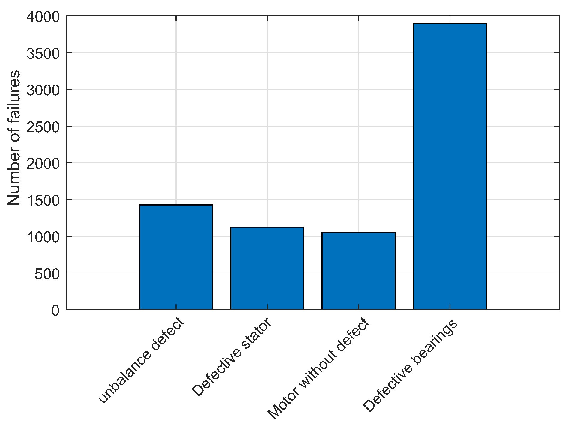
Figure 62.
ROC curve for defective stator.
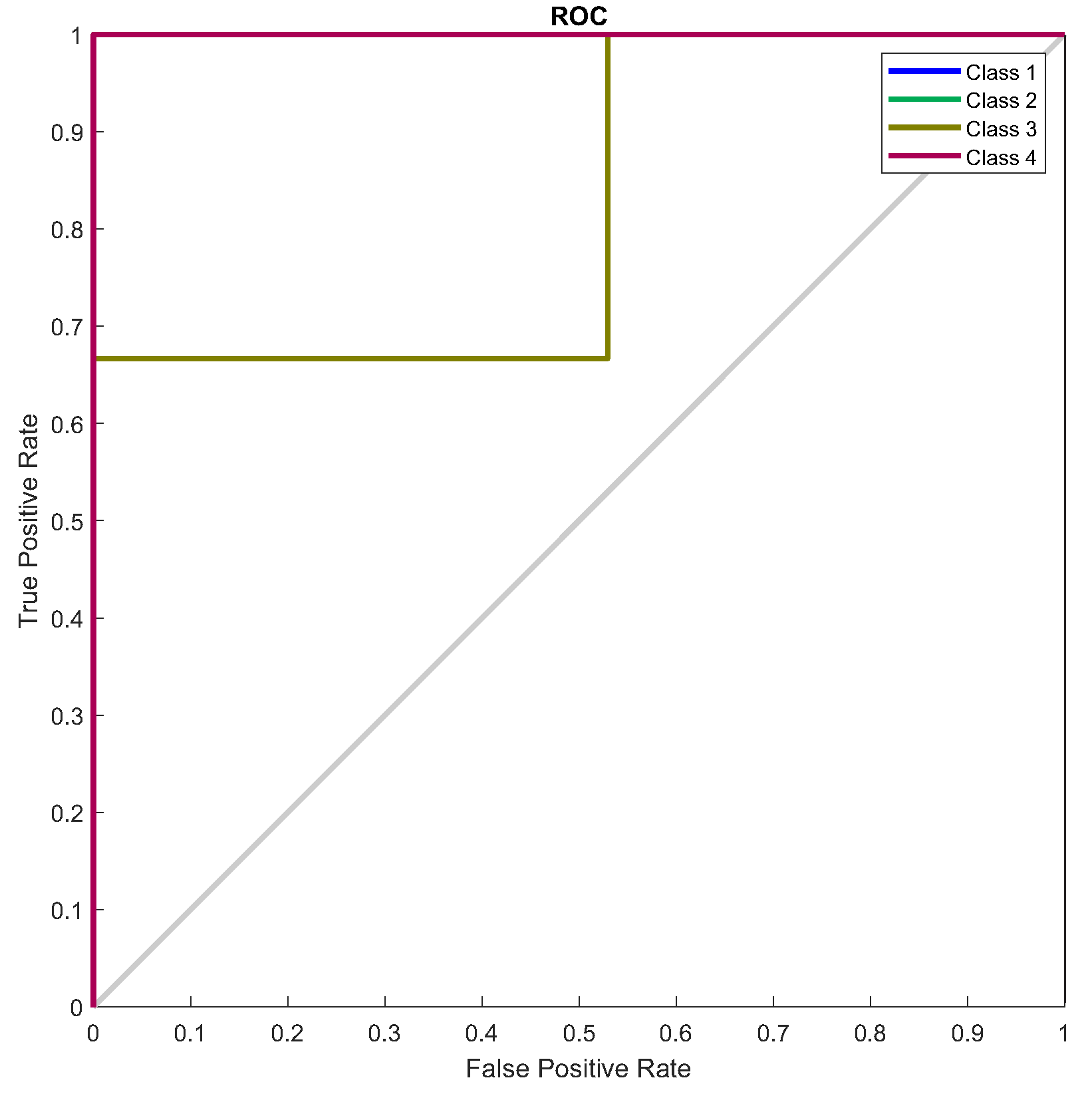
Figure 63.
Confusion matrix for defective stator.
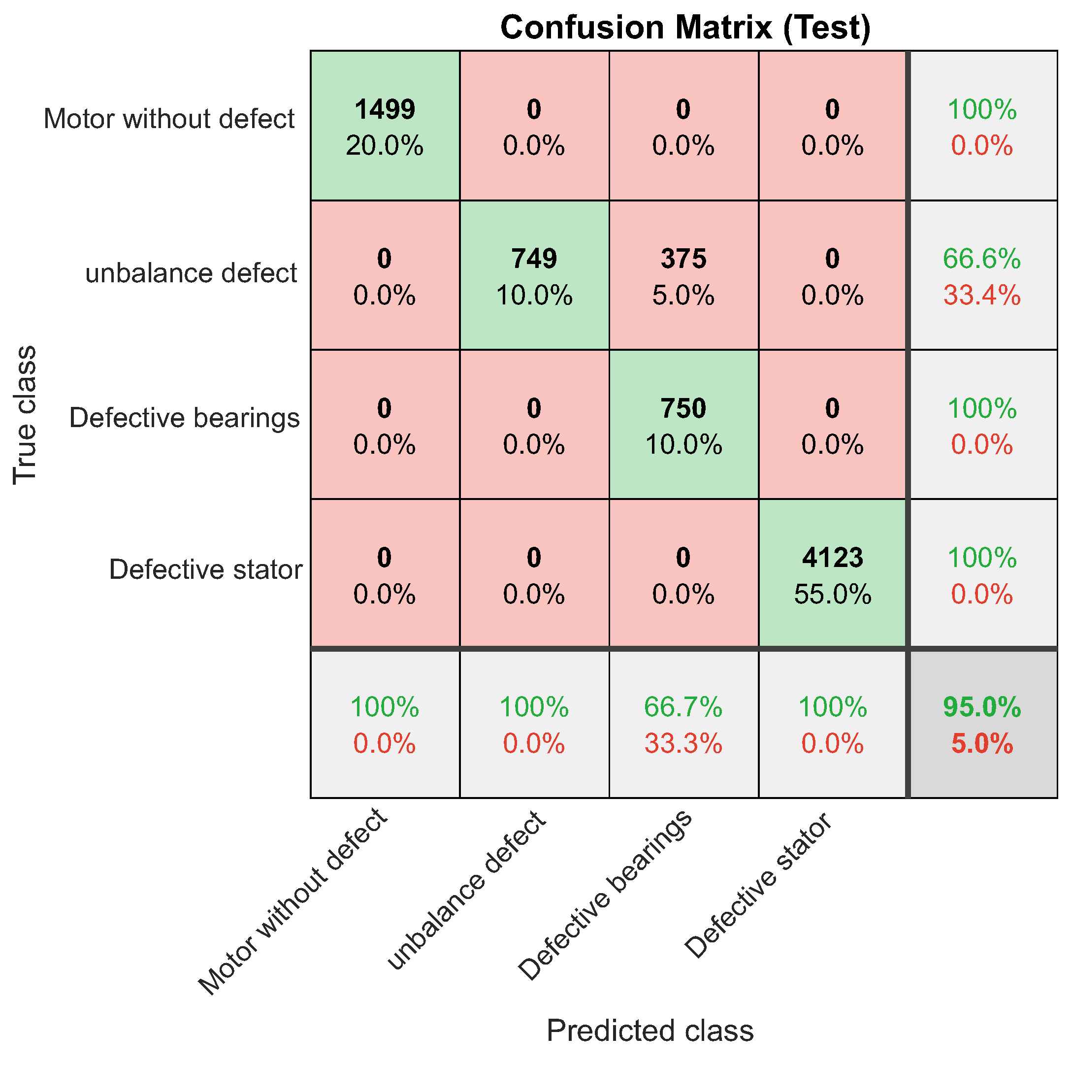
Figure 64.
Faults classified for defective stator.
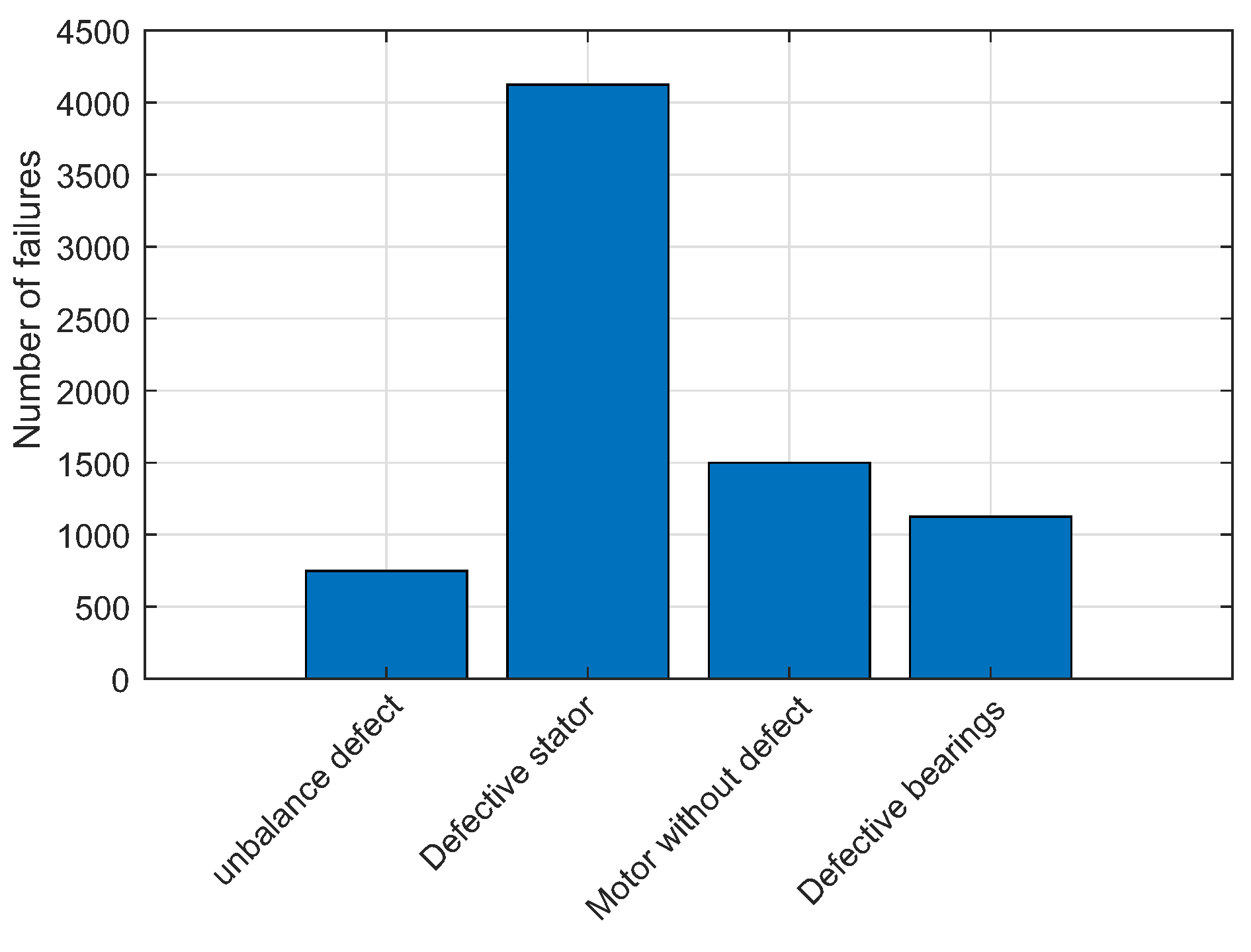

Table 1.
Characteristics of the three-phase induction motor.
| Features | Data |
|---|---|
| Power | 1.1 HP |
| Speed | 1720 RPM |
| Frequency | 60 Hz |
| FS | 1.5 |
| Ip / In | 7.8 A |
| Voltage | 220 / 380V |
| Current | 4.43 / 2.56 A |
Table 2.
Characteristics of the current sensor.
| Features | Technical Data |
|---|---|
| Rated Input | 5 A (AC) |
| Rated Output | 5V (DC) |
| Accuracy error | 0.5% |
| Linearity | 0.5 % |
Table 3.
Characteristics of the vibration sensor.
| Features | Technical Data |
|---|---|
| Sensor Chip | ADLX335 |
| Operating voltage range | 3 to 5V (DC) |
| Supply current | A |
| Scale range | g |
| Operating temperature | C to C |
| Sensitivity | 300mV/g |
| Accuracy | % |
Table 4.
Characteristics of the temperature sensor.
| Features | Technical Data |
|---|---|
| Operating voltage | 4 to 30V |
| Drain current | <A |
| Measuring range | to C |
| Sensitivity | 10mV/ oC |
| Accuracy | C (at C) |
Table 5.
Characteristics of the NI USB-6008.
| Features | Technical Data |
|---|---|
| Supply voltage | 5VDC |
| Analog inputs 12/14 bits | 8 |
| Analog outputs 12 bits | 2 |
| 32-bit | 5 Mhz counter |
| Sampling Rate | 1KHz |
| Acquisition Mode | Continuous Samples |
| Recommended Software | LabVIEW |
Table 6.
Best parameters found from the trained network.
| Delay | Feedback | Neurons-H1 | Neurons-H2 |
|---|---|---|---|
| 3 | 4 | 10 | 10 |
Table 7.
Performance of the trained NARX neural network.
| Accuracy | Precision total | Recall | F1 Score |
|---|---|---|---|
| 0.99 | 1.0 | 0.99 | 0.99 |
Table 8.
Performance of NARX neural network for imbalance defect.
| Accuracy | Precision total | Recall | F1 Score |
|---|---|---|---|
| 0.94 | 0.96 | 0.98 | 0.97 |
Table 9.
Performance of NARX neural network for imbalance defect.
| Accuracy | Precision total | Recall | F1 Score |
|---|---|---|---|
| 0.95 | 1.0 | 0.95 | 0.97 |
Table 10.
NARX Neural Network Performance for Defective Bearings.
| Accuracy | Precision total | Recall | F1 Score |
|---|---|---|---|
| 0.98 | 1.0 | 0.98 | 0.99 |
Table 11.
Performance of NARX neural network for defective stator.
| Accuracy | Precision total | Recall | F1 Score |
|---|---|---|---|
| 0.95 | 1.0 | 0.95 | 0.97 |
Table 12.
Performance of the NARX neural network for each type of fault classified.
| Motor without defect | unbalance defect | Defective bearings | Defective stator |
|---|---|---|---|
| 94.2% | 95% | 98% | 95% |
Disclaimer/Publisher’s Note: The statements, opinions and data contained in all publications are solely those of the individual author(s) and contributor(s) and not of MDPI and/or the editor(s). MDPI and/or the editor(s) disclaim responsibility for any injury to people or property resulting from any ideas, methods, instructions or products referred to in the content. |
© 2024 by the authors. Licensee MDPI, Basel, Switzerland. This article is an open access article distributed under the terms and conditions of the Creative Commons Attribution (CC BY) license (http://creativecommons.org/licenses/by/4.0/).
Copyright: This open access article is published under a Creative Commons CC BY 4.0 license, which permit the free download, distribution, and reuse, provided that the author and preprint are cited in any reuse.


