Submitted:
13 June 2024
Posted:
20 June 2024
You are already at the latest version
Abstract
Robotic path planning and navigation algorithms enable autonomous mobile robots to navigate complex environments. These algorithms allow robots to be deployed in search and rescue missions, where they can locate victims in hazardous areas inaccessible to humans. Additionally, autonomous driving algorithms hold the potential to revolutionize transportation by enabling self-driving cars to navigate roads safely and efficiently. This paper focuses on developing an algorithm for autonomous navigation of the mobile robot (Tortoise bot) using robot operating system (ROS), based on publish-subscribe communication facilitating seamless interaction between various nodes. Tortoise Bot is a differential wheeled robot whose movement is based on two separately driven wheels placed on either side of the robot body. The Raspberry Pi acts as the controller. A 360-degree LiDAR and RGB-D camera are used for creating a 3D map of the environment. Various state-of-the art software tools, such as Gazebo, Ubuntu, MATLAB and RPI imager are used. Initially, a simulation based on simple obstacle avoidance is done using gazebo and MATLAB. Another simulation based on trajectory tracking is implemented using MATLAB to study the kinematic model. Online navigation and path planning are executed with the help of teleoperation and Dynamic Window Approach algorithm. A novel Wander algorithm is created that avoids obstacles on its path. Object recognition is also implemented during autonomous navigation using YOLO.
Keywords:
Autonomous mobile robots
; path planning
; machine learning
Introduction
Robotics has emerged as a transformative field, revolutionizing various aspects of human life. One key area of advancement lies in Human-Robot Interaction (HRI) [1,2,3,4,5,6,7]. This interaction takes diverse forms, from collaborative robots in industrial settings to assistive robots for people with disabilities. Sensorized garment-controlled robotic wheelchairs, for instance, offer intuitive control for users, improving their mobility and independence [8,9,10,11,12,13,14]. Path planning algorithms are crucial for enabling autonomous mobile robots to navigate complex environments safely and efficiently [15,16,17,18]. Robotics also plays a significant role in rehabilitation, with robots providing targeted assistance and feedback to patients recovering from injuries or illnesses [19,20,21,22]. Looking beyond physical interaction, the integration of robotics with virtual reality (VR) opens doors for novel rehabilitation and training experiences [23,24,25,26,27].
Furthermore, advancements in robot perception are crucial for successful navigation and interaction with the environment. Simultaneous Localization and Mapping (SLAM) is a technique that allows robots to build a map of their surroundings while simultaneously keeping track of their location within that map [19,20,21]. This is particularly important for robots operating in dynamic or unfamiliar environments. Visual SLAM (vSLAM) utilizes cameras as the primary sensor for this purpose, offering advantages in terms of cost and information richness [20,21,22]. As these areas continue to evolve, robotics holds immense promise for enhancing human capabilities and fostering a future of seamless human-machine collaboration.
This report explores ROS Noetic, emphasizing their support for robotics development. SLAM methods include V-SLAM and LiDAR-SLAM, with LiDAR favored for its range and reliability, suitable for environments like smart farms. Cartographer and Gmapping are popular LiDAR-based SLAM algorithms, showing promise in various applications.
Motivation
ROS enables robust robotics development with its modular architecture, fostering code reuse and rapid prototyping. Its vibrant community offers a vast repository of resources, encouraging collaboration and innovation. The publish-subscribe communication system allows for seamless interaction between nodes, enabling scalable and adaptable robotic systems.
Problem Statement
- Dynamic obstacle avoidance- Developing an algorithm that can effectively handle obstacles in real-time, allowing the robot to navigate safely and efficiently.
- Object recognition- The robot will identify objects that appears in front of the RGB camera on its way to the goal or after reaching the goal point.
- Low Power Consumption and cost effectiveness- Developing a system that utilizes low-power and cost effective hardware components.
Objectives
- Study of Obstacle avoidance using Gazebo simulation
- Study of kinematic model using Matlab simulation
- To implement online navigation and path planning(using DWA algorithm) of Tortoise bot(AMR) using ROS
- Wander algorithm along with obstacle avoidance
- Object Recognition
Performance evaluation of ROS based SLAM algorithms for handheld indoor mapping and tracking systems
ROS is a specialized open-source software platform that is used to program and control robots. ROS includes libraries, programming tools, graphical tools, tools for direct control communication with hardware, and libraries for data retrieval from sensors and devices. ROS’s programming environment makes it easier to construct complex robot capabilities, such as teleoperation and navigation. ROS functions similar to a network made up of several nodes, each with a specific function that corresponds to the robot’s parts. Rather than agreeing to use the same programming language, each node can be created and coded in accordance with the developer’s concept. C++ can be used to create one node, whereas Python can be used to create another node. As a result, developers no longer need to be concerned about the robot’s hardware because ROS provides a common interface for operating the robot’s hardware. Thus, instead of dealing with the specific hardware API, the software becomes the primary focus. This makes robot software development considerably easier, independent, and versatile to use.
LiDAR Based Trajectory-Tracking of an Autonomous Differential Drive Mobile Robot Using Fuzzy Sliding Mode Controller
Amid the COVID-19 pandemic, online shopping surges, prompting factories to adopt automated logistic technologies. Research focuses on controlling mobile robots, notably Differential Drive Mobile Robots (DDMRs) for path following. However, controlling Autonomous DDMRs poses challenges due to nonlinearity and nonholonomic properties. While many techniques address kinematics, dynamics consideration becomes crucial at high speeds. Some designs integrate both kinematic and dynamic models. Trajectory tracking remains vital, with some methods struggling to compensate for initial position errors. Time constraints on planned paths cause speed variations, affecting DDMR performance.
Field Evaluation of Path-Planning Algorithms for Autonomous Mobile Robot in Smart Farms
Path planning is crucial across various sectors, including agriculture. Smart farms require automated path-planning techniques for efficiency. This study investigates algorithms suitable for simultaneous localization and mapping (SLAM) in smart farms. It explores grid-based Dijkstra, A*, sampling-based RRT, and RRT* algorithms. Experiments in static and dynamic environments test path planning for agricultural robots, emphasizing accuracy over speed to minimize crop damage. The A* algorithm emerges as suitable for smart farms due to its effectiveness. These findings enable efficient navigation in smart farms, emphasizing the importance of selecting the optimal algorithm for specific purposes.
Methodology and Hardware Details
1)Lidar sensor
LiDAR is a remote sensing technology that uses laser light to measure distances with high precision. In the context of a robot like ”tortoise bot,” LiDAR can serve several purposes:
- Obstacle Detection and Avoidance-LiDAR sensors can be used to create a detailed 3D map of the robot’s surroundings. This map can be used to identify obstacles in the environment, allowing the robot to plan its movements and avoid collisions.
- Navigation-LiDAR data can assist in navigation tasks. By continuously scanning the surroundings, the robot can localize itself and navigate through complex environments.
- Mapping- LiDAR can be used to create detailed maps of indoor or outdoor spaces. This is particularly useful for tasks such as exploration, surveillance, or search and rescue.
- Object Recognition-data can contribute to object recognition and classification, allowing the robot to identify and interact with specific objects in its environment.
- Autonomous Operation- In combination with other sensors and algorithms, LiDAR can contribute to the development of autonomous robot behaviour. For example, a robot equipped with LiDAR can navigate a room, avoiding obstacles and reaching its destination autonomously.
- Simultaneous Localization and Mapping (SLAM)- LiDAR is often used in SLAM algorithms, where the robot builds a map of its environment while simultaneously determining its own location within that map
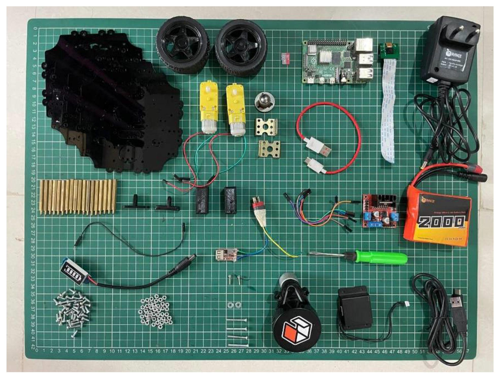
Figure 1.
Tortoise bot components.
2)Raspberry pi
The incorporation of a Raspberry Pi into the design of the Tortoise Bot introduces a new dimension of computational capability and versatility. Serving as the central processing unit, the Raspberry Pi empowers the Tortoise Bot with the ability to execute intricate algorithms, make informed decisions, and precisely coordinate its movements. The GPIO pins of the Raspberry Pi facilitate seamless integration with an array of sensors, such as distance sensors, cameras, and environmental sensors, providing the Tortoise Bot with a heightened awareness of its surroundings. This integration allows the bot to navigate with meticulous precision. Leveraging machine learning algorithms, the Raspberry Pi enables the Tortoise Bot to adapt its behaviour over time, learning from experiences and optimizing its performance. The HDMI output of the Raspberry Pi forms the basis for a user-friendly interface, granting users the capability to monitor the bot’s status, customize its tasks, and receive real-time feedback. With programming flexibility, USB ports for additional components, and network connectivity for remote monitoring, the Raspberry Pi transforms the Tortoise Bot into a sophisticated and educational platform, blending patient, deliberate movement with the computational prowess of modern technology.
3)RGB Camera
Integrating an RGB (Red, Green, Blue) camera into the Tortoise Bot can significantly enhance its capabilities, providing a visual perception system that aligns with the bot’s slow and methodical nature. Here’s a brief overview of how an RGB camera can benefit the Tortoise Bot
- Visual Sensing -The RGB camera serves as the eyes of the Tortoise Bot, allowing it to perceive and interpret the surrounding environment in colour. This visual input can be crucial for tasks such as object recognition, pathfinding, and navigation.
- Colour-Based Object Detection- Leveraging the RGB capabilities, the Tortoise Bot can identify and differentiate objects based on their colours. This can be useful in scenarios where the bot needs to interact with or avoid specific objects based on their visual characteristics.
- Environment Mapping- The RGB camera enables the Tortoise Bot to capture images of its surroundings, facilitating the creation of a visual map. This map can be utilized for navigation, helping the bot to plan its movements and avoid obstacles with a heightened level of precision.
- Line Following- For applications involving line-following tasks, an RGB camera can detect colour variations on the surface, allowing the Tortoise Bot to follow a designated path accurately. This is particularly relevant for tasks in controlled environments or on specialized tracks.
- Visual Feedback for Users- Integrating the RGB camera into the Tortoise Bot’s user interface provides real-time visual feedback to users. This visual information can be displayed on a monitor or interface, allowing users to see what the bot ”sees” and aiding in task monitoring.
- Adaptive Lighting Conditions- RGB cameras can adjust to different lighting conditions, providing flexibility for the Tortoise Bot to operate in various environments. This adaptability ensures reliable performance in both indoor and outdoor settings.
4)Wheels
Castor wheel
Incorporating caster wheels enhances the Tortoise Bot’s mobility and maneuverability. A caster wheel, with its omni-directional movement, allows precise turns and navigation without changing orientation. This aligns with the deliberate nature of the Tortoise Bot, enabling controlled movements. It’s especially beneficial for tasks requiring tight turns and versatility.
Side wheels
Differential drive robots employ two wheels on each side, with a differential mechanism enabling independent rotation. When wheels move uniformly, the robot advances straight. Differential control allows for varied wheel speeds, facilitating precise turns and pivots, vital for maneuvering in tight spaces. Mathematically, adjusting wheel velocities achieves desired trajectories, making these robots adept at navigating curves and intricate tasks, enhancing their effectiveness in robotics research and automation.
5)Lithium ion battery
A 2000 mAh lithium-ion (Li-ion) battery is commonly employed in robots due to its favorable characteristics. The compact size and lightweight nature of Li-ion batteries make them ideal for powering robots, allowing for efficient energy storage without adding excessive weight that could impede mobility. The high energy density of Li-ion batteries ensures that robots can operate for extended periods on a single charge, promoting prolonged autonomy and reducing the need for frequent recharging. This is crucial for robots engaged in tasks such as exploration, surveillance, or household chores, where sustained operation is essential. Additionally, Li-ion batteries exhibit a low self-discharge rate, retaining stored energy for longer durations when not in use. This feature is advantageous for robots that may remain inactive for periods between tasks. The ability of Li-ion batteries to provide a consistent voltage throughout the discharge cycle ensures stable and reliable power delivery. This reliability is crucial for the consistent performance of various robot components, including motors and sensors.
6)Dual channel motor driver
The Dual Channel Motor Driver is vital to the Tortoise Bot’s design philosophy, orchestrating its deliberate movements. It controls dual motors independently, dictating direction and speed with precision. Utilizing an H-bridge configuration, it enables nuanced navigation in various directions, reflecting the bot’s patient nature. Supporting features like PWM ensure smooth movement, while current sensing and protection mechanisms enhance reliability. Integrated with microcontroller interfaces, it enables programmability, empowering the bot’s precision and purposeful motion.
7)Battery operated(Brushed DC) motor
BO (Brushed DC) motors, comprising a rotating armature and stationary magnetic field, are common in propulsion. Brushes and commutators switch current flow, driving rotational motion. In Tortoise Bot, they provide locomotion, controlling shaft rotation for movement and turning. Favored for simplicity and cost-effectiveness, they convert electrical energy for mechanical tasks. Motor selection considers torque, speed, and application needs for effective robotic interaction.
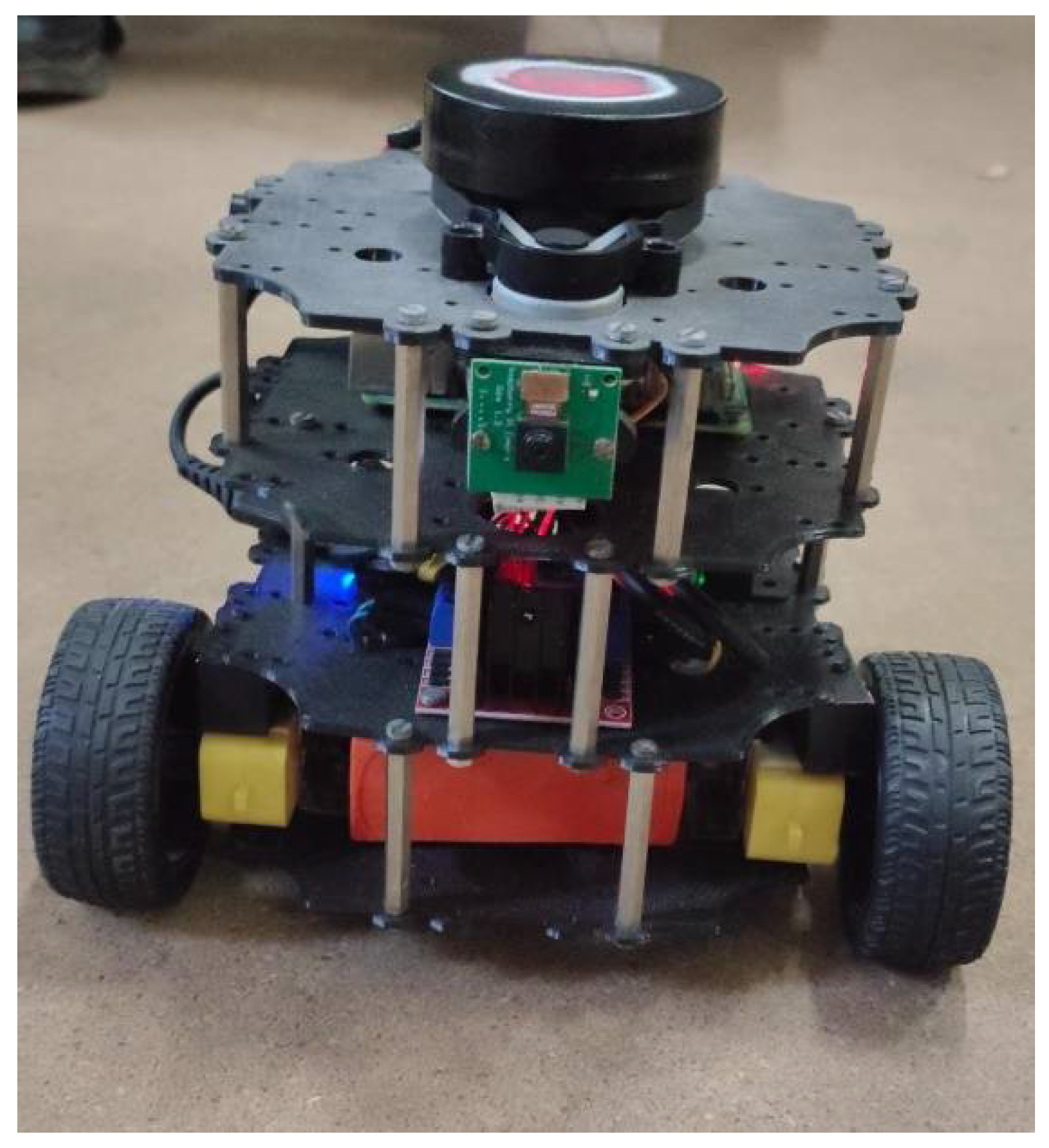
Figure 2.
Tortoise bot.
Methodology
1)Gazebo simulation
Gazebo simulation is a robust open-source tool for simulating the dynamics of robots in diverse environments. Widely employed alongside the Robot Operating System (ROS), Gazebo enables developers to model and validate complex robotic systems. Its realistic simulation environment allows testing of algorithms and control strategies before implementation on physical robots, reducing development time and costs. Gazebo supports various sensors, actuators, and physics engines, providing an accurate platform for researchers and engineers to iterate and refine their robotic applications in a virtual setting. This facilitates the optimization of robot performance, enhancing overall reliability and efficiency in real-world scenarios. Here, a simulation of simple obstacle avoidance for a differential robot(turtlebot) is conducted in order to simulate the condition for the tortoise bot in real-world situations. The code for this gazebo simulation This MATLAB code is a script designed to control a mobile robot using ROS (Robot Operating System) commands and to visualize its trajectory and velocity profile. Let’s break down the script’s functionality in detail:
1)Initialization -The code initializes ROS with a specified IP address and port number using rosinit(). It creates a publisher robot for sending velocity commands to the mobile base. A subscriber laser is set up to receive laser scan data from the robot’s environment. The script also subscribes to odometry data using rossubscriber() to track the robot’s position and orientation.
2)Motion Control Loop- Inside the main loop, the script continuously receives laser scan data using receive(laser). It processes the laser scan data to compute the distance to the closest obstacle. Based on the distance threshold (distanceThreshold), the script decides the robot’s action. If the robot is too close to an obstacle, it sets commands to spin and move backward slightly; otherwise, it continues moving forward. These velocity commands (velmsg) are sent to the robot using send(robot, velmsg). Odometry data is also received and used to track the robot’s position and velocity.
3)Visualization- The script plots the robot’s trajectory.
4)Termination- The loop runs for a specified duration (100 seconds) using tic() and toc() functions. After the loop ends, the script shuts down the ROS node using rosshutdown().
2)Kinematic model simulation
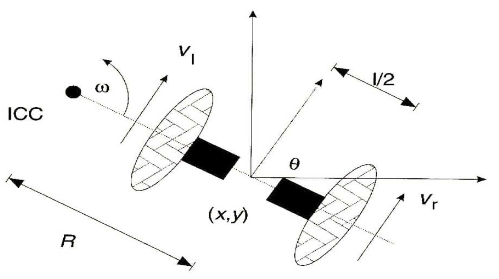
Vr = w(R + l/2)
Vl = w(R − l/2)
w =(Vr − Vl)/lR=l(Vl + Vr)/2(Vr − Vl)
Fig. 4.2: Kinematic model of differential robot
x’=v cosθ, y′ = vsinθ, θ′ = w
Figure 3.
Conceptual robot’s kinematics.
Algorithm
- Set initial position
- Set left and right wheel velocities
- Introduce noise into velocity commands if necessary using rand function, for realistic behaviour
- Obtain the trajectory, position and orientation graphs
3)Dynamic Window Approach
Dynamic Window Approach (DWA) is a popular algorithm used in mobile robotics for local navigation and obstacle avoidance.In order to consider the limited accelerations by the motors the overall search space is reduced to the ”dynamic window” which contains only the velocities that can be reached within the next time interval.
Local Goal: The robot has a local goal it wants to reach. This could be a specific point in the environment or a goal defined by a path.
Dynamic Window: The robot considers its current state (position, velocity) and generates a ”dynamic window” of allowable velocities. This window is determined by the robot’s kinematic constraints (maximum velocity, maximum acceleration) and the obstacles detected in the environment.
Velocity Sampling: Within this dynamic window, the robot samples different velocities and predicts the robot’s future trajectories for each sampled velocity. Trajectory Evaluation: Each sampled trajectory is evaluated based on predefined criteria such as proximity to obstacles, distance to the goal, and smoothness of the trajectory.
Select Best Trajectory: The trajectory with the highest score (based on the evaluation criteria) is chosen as the next action for the robot to execute. Update: The robot continuously updates its state, reevaluates its dynamic window based on new sensor information, and repeats the process to navigate through the environment dynamically. Overall, DWA enables the robot to navigate safely and efficiently in dynamic environments by considering its kinematic constraints and dynamically adjusting its trajectory based on real-time sensor information.
Optimization of Objective Function
The objective function G(v,w)=σ(α(heading(v, w)) + β(dist(v, w)) + γ(vel(v, w)
1)Target heading Heading is a measure of progress to the goal location.It is maximal if the robot moves directly towards the target.
2)Distance Dist is the distance to the closest obstacle on the trajectory.The smaller the distance to the obstacle, the higher is the robot’s desire to move around it.
3.Velocity Vel is the forward velocity of the robot.Supports fast movements.
Lidar:Data Transmission and Reception
LiDAR:Data transmission and reception Sending and receiving sensor data LiDAR (Light Detection and Ranging) technology has revolutionized various industries, from autonomous vehicles and robotics to environmental monitoring and urban planning. Sending and receiving data from a LiDAR sensor involves a systematic approach to capture, process, and analyze the acquired information. The process begins with establishing a connection between the LiDAR sensor and the host device, typically using interfaces like USB, UART, or Ethernet. This connection enables bidirectional communication, allowing commands to be sent to the sensor and data to be received from it. Once connected, the LiDAR sensor needs to be initialized with specific configuration settings and commands to initiate the data acquisition process. These settings can include parameters like scan resolution, scanning frequency, and data output format, depending on the requirements of your application. With the sensor initialized, it starts emitting laser pulses and collecting the reflected signals to measure distances and create a point cloud of the surrounding environment. The collected data is then transmitted back to the host device in real-time or stored temporarily for later retrieval.Upon receiving the raw data from the LiDAR sensor, the next step involves processing this data to extract meaningful information. This can include filtering out noise, calibrating the measurements, and transforming the raw point cloud into a usable format, such as 3D maps or object recognition datasets. Once the data is processed, it can be further analyzed to derive insights tailored to specific applications. For instance, in autonomous vehicles, the LiDAR data is crucial for detecting obstacles, identifying road features, and navigating safely through complex environments.
Teleoperation
The term "teleoperation" refers to the operation of a system or machine at a distance. It is sometimes referred to as “remote control” and is most often associated with robotics and mobile robots. Teleoperated robots help human users complete both simple and complex tasks from a distance.
Map Generation Using SLAM
SLAM (Simultaneous Localization and Mapping) is a technique used in robotics to generate maps of unknown environments while simultaneously determining the robot’s position within those maps. SLAM combines the datas from LiDAR and camera with motion to create and update a map of an environment while simultaneously determining the robot’s location within that map, allowing for autonomous navigation in unknown surroundings. Here we are trying to generate the map of our classroom.The classroom includes objects like benches and desks.
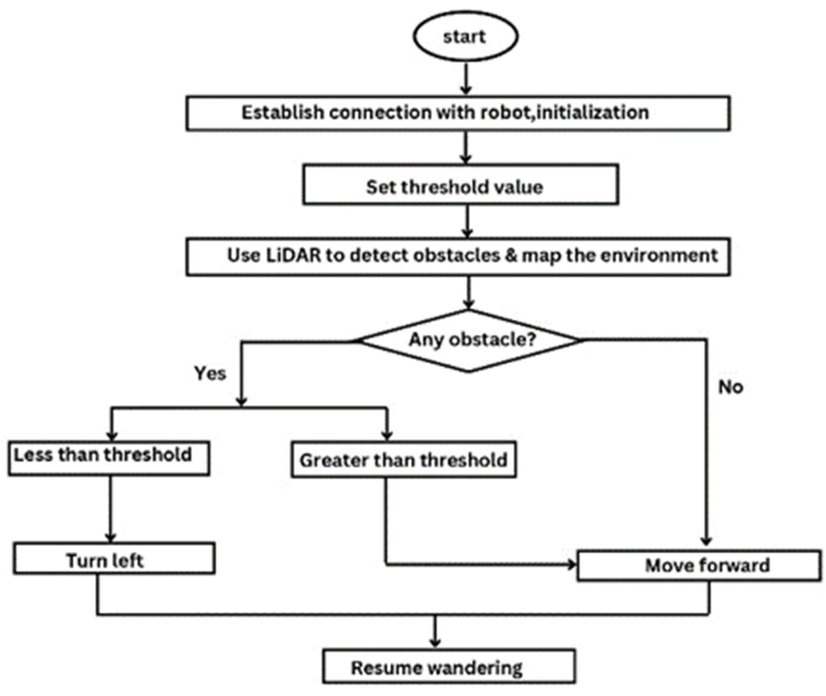
4)Wander algorithm
The script in wander algorithm imports necessary libraries and modules for ROS, threading, and message types. The global variable is initialized for publishing messages, storing robot state, and managing threads. Publish Thread class manages publishing velocity commands to control the robot’s movement. It runs in a separate thread and continuously updates the robot’s velocity based on provided parameters. The results are taken from processing laser scan data and updates the robot’s velocity accordingly. Laser function is a callback for handling laser scan messages. It processes the laser scan data, sends it for processing, and updates the robot’s velocity. Another function reads keyboard input for controlling the robot’s movement. The main function initializes ROS, sets up parameters, subscribes to laser scan data, and enters a loop to read keyboard input for controlling the robot. It continuously updates the robot’s velocity based on user input until the script is terminated. Overall, the novel script allows the user to control the robot’s movement using keyboard input while processing laser scan data to avoid obstacles in its environment.
Figure 4.
Robotic simulation prepared under Gazebo (ROS).
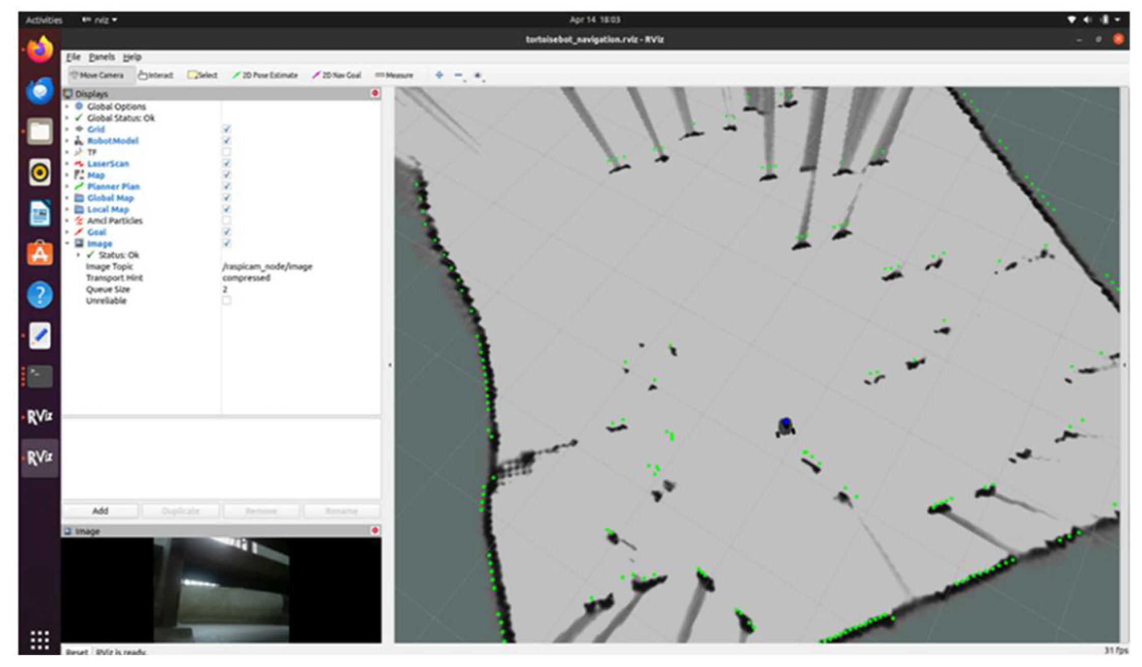
Figure 5.
Online Obstacle Avoidance Algorithm.
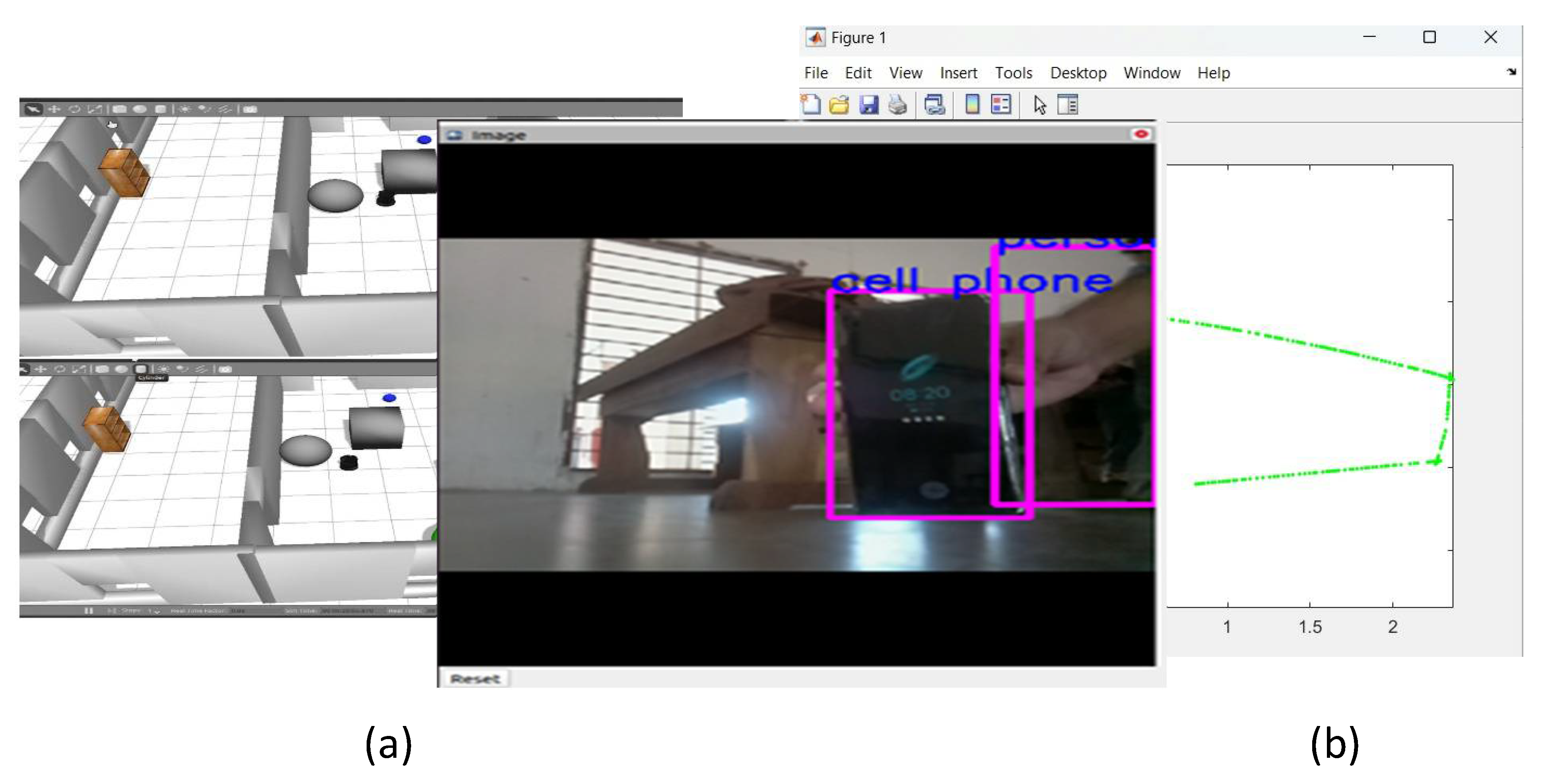
5)Object recognition
We are employing the YOLO (You Only Look Once) algorithm for object recognition within our system.
- Input Acquisition: The robot collects visual data using onboard cameras or sensors, capturing images or video frames of its surroundings.
- Preprocessing: The acquired images may undergo preprocessing steps such as resizing, normalization, or augmentation to enhance the quality and suitability for analysis. • YOLO Algorithm Implementation: YOLO is employed as a deep learning based object recognition algorithm. It operates by dividing the input image into a grid and simultaneously predicts bounding boxes and class probabilities for each grid cell.
- Object Recognition: YOLO processes the image and identifies regions containing objects, drawing bounding boxes around them and assigning a class label to each detected object. YOLO is known for its real-time performance and accuracy in detecting multiple objects within a single frame.
- Object Classification: Once objects are detected, the robot can classify them into predefined categories such as ”person,” ”phone,” ”chair,” etc. This classification enables the robot to understand the identity of the objects it perceives.
- Feedback and Iteration: The robot continually refines its object recognition capabilities through feedback mechanisms, such as learning from misclassifications or updating its object database over time. Object recognition empowers the robot to interpret its environment, navigate safely, and perform tasks effectively in diverse real-world scenarios.
Results
Figure 6.
Results of the kinematic simulation of the autonomous mobile robot. (a) A simulation was prepared under realtime 3D ROS (Gazebo) environment. (b) The planned trajectory was obtained and plotted using the algorithm described, above.
Figure 6.
Results of the kinematic simulation of the autonomous mobile robot. (a) A simulation was prepared under realtime 3D ROS (Gazebo) environment. (b) The planned trajectory was obtained and plotted using the algorithm described, above.
| No | Cases | Output |
| 1 | Equal, constant wheel velocity | Straight line |
| 2 | Unequal, constant wheel velocity | Circle |
| 3 | Equal, noisy wheel velocity | Distorted straight line |
| 4 | Unequal, noisy wheel velocity | Multiple Circles |
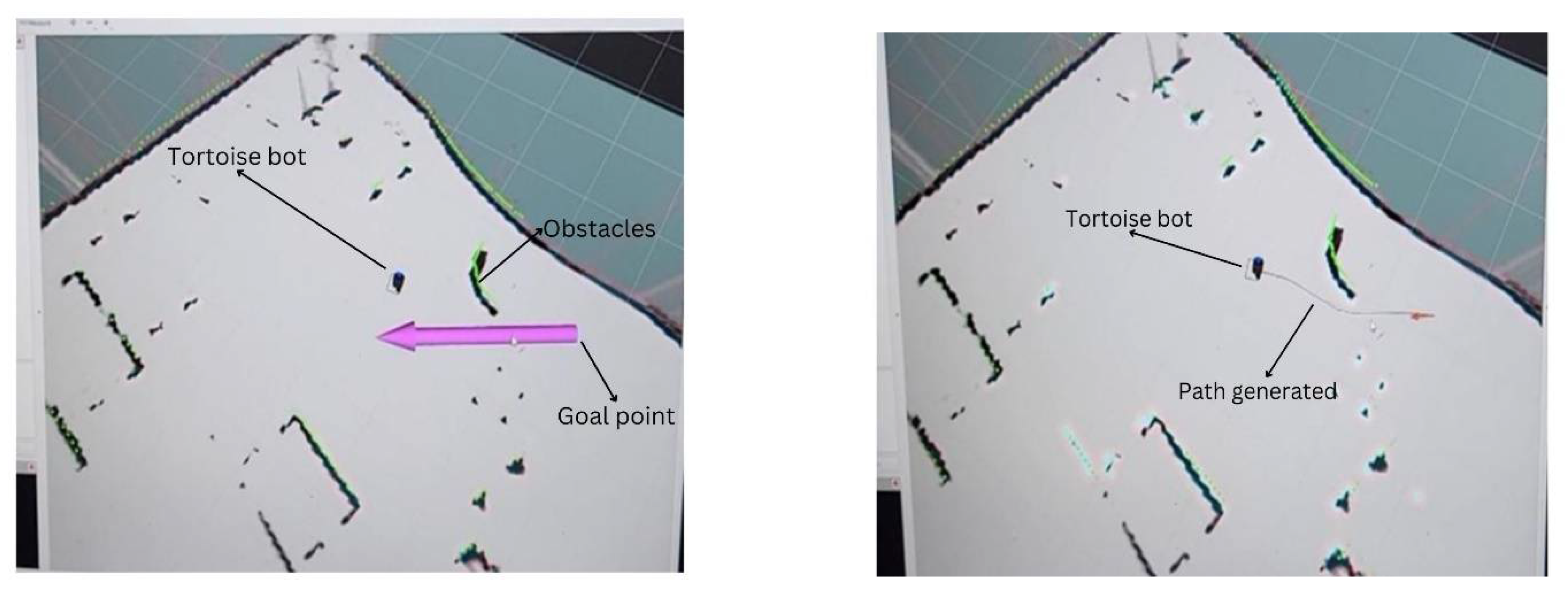
3)DWA
A goal point is being assigned to the robot via RViz, which acts as a visualization tool for robot control. The robot’s onboard navigation system process the goal point. The system calculates a path from the robot’s current position to the specified goal using path planning algorithm. Once the path is calculated, the robot executes motion control commands to move towards the goal while avoiding obstacles along the way.
4)Object recognition
The raspberry pi camera identifies the object and returns the confidence values. From the following figure we infer that a cell phone and person is correctly identified.
Figure 6.
A screen shot of a perspective view as an output frame in RGB is shown after running YOLO on the robotic embedded system.
Figure 6.
A screen shot of a perspective view as an output frame in RGB is shown after running YOLO on the robotic embedded system.
Conclusion
Our Autonomous Mobile Robot (AMR) equipped with sensors such as cameras and LiDAR, operates on the ROS (Robot Operating System) platform. Leveraging online navigation and path planning capabilities, coupled with object recognition functionality using YOLO, the robot successfully navigates its environment while avoiding obstacles to reach specified goals autonomously. This integration of hard- ware and software technologies underscores the versatility and efficiency of our robotic system in real-world applications, marking a significant milestone in thedevelopmentof autonomous robotic platforms.
References
- Murphy, R. R., Nomura, T., Billard, A., & Burke, J. L. (2010). Human–robot interaction. IEEE robotics & automation magazine, 17(2), 85-89.
- Marken, R., Kennaway, R., & Gulrez, T. (2022). Behavioral illusions: The snark is a boojum. Theory & Psychology, 32(3), 491-514. [CrossRef]
- Zaheer, S., & Gulrez, T. (2015). A Path Planning Technique For Autonomous Mobile Robot Using Free-Configuration Eigenspaces. International Journal of Robotics and Automation (IJRA), 6(1), 14.
- Al-Hmouz, R., Gulrez, T., & Al-Jumaily, A. (2004, December). Probabilistic road maps with obstacle avoidance in cluttered dynamic environment. In Proceedings of the 2004 Intelligent Sensors, Sensor Networks and Information Processing Conference, 2004. (pp. 241-245). IEEE.
- Nguyen, Q. H., Johnson, P., & Latham, D. (2022). Performance evaluation of ROS-based SLAM algorithms for handheld indoor mapping and tracking systems. IEEE Sensors Journal, 23(1), 706-714. [CrossRef]
- Zaheer, S., Jayaraju, M., & Gulrez, T. (2015, March). Performance analysis of path planning techniques for autonomous mobile robots. In 2015 IEEE international conference on electrical, computer and communication technologies (ICECCT) (pp. 1-5). IEEE.
- Kazerouni, I. A., Fitzgerald, L., Dooly, G., & Toal, D. (2022). A survey of state-of-the-art on visual SLAM. Expert Systems with Applications, 205, 117734. [CrossRef]
- Poh, C., Gulrez, T., & Konak, M. (2021, March). Minimal neural networks for real-time online nonlinear system identification. In 2021 IEEE Aerospace Conference (50100) (pp. 1-9). IEEE.
- Zhang, L., Zhang, Y., & Li, Y. (2020). Path planning for indoor mobile robot based on deep learning. Optik, 219, 165096. [CrossRef]
- Gulrez, T., Zaheer, S., & Abdallah, Y. (2009, December). Autonomous trajectory learning using free configuration-eigenspaces. In 2009 IEEE International Symposium on Signal Processing and Information Technology (ISSPIT) (pp. 424-429). IEEE.
- Pour, P. A., Gulrez, T., AlZoubi, O., Gargiulo, G., & Calvo, R. A. (2008, December). Brain-computer interface: Next generation thought controlled distributed video game development platform. In 2008 IEEE Symposium On Computational Intelligence and Games (pp. 251-257). IEEE.
- Gulrez, T., Kekoc, V., Gaurvit, E., Schuhmacher, M., & Mills, T. (2023, March). Machine Learning Enabled Mixed Reality Systems-For Evaluation and Validation of Augmented Experience in Aircraft Maintenance. In Proceedings of the 2023 7th International Conference on Virtual and Augmented Reality Simulations (pp. 77-83).
- Kavaliauskaitė, D., Gulrez, T., & Mansell, W. (2023). What is the relationship between spontaneous interpersonal synchronization and feeling of connectedness? A study of small groups of students using MIDI percussion instruments. Psychology of Music, 03057356231207049. [CrossRef]
- Gulrez, T., & Yoon, W. J. (2018). Cutaneous haptic feedback system and methods of use. US Patent, (9,946).
- Cabibihan, J. J., Alhaddad, A. Y., Gulrez, T., & Yoon, W. J. (2021). Influence of Visual and Haptic Feedback on the Detection of Threshold Forces in a Surgical Grasping Task. IEEE Robotics and Automation Letters 6, 5525–5532. [CrossRef]
- Gulrez, T., & Tognetti, A. (2014). A sensorized garment controlled virtual robotic wheelchair. Journal of Intelligent & Robotic Systems, 74, 847-868. [CrossRef]
- Satoshi, T., Gulrez, T., Herath, D. C., & Dissanayake, G. W. M. (2005). Environmental recognition for autonomous robot using slam. real time path planning with dynamical localised voronoi division. International Journal of Japan Society of Mech. Engg (JSME), 3, 904-911.
- Zaheer, S., & Gulrez, T. (2015). A Path Planning Technique For Autonomous Mobile Robot Using Free-Configuration Eigenspaces. International Journal of Robotics and Automation (IJRA), 6(1), 14.
- Gulrez, T., Tognetti, A., Yoon, W. J., Kavakli, M., & Cabibihan, J. J. (2016). A hands-free interface for controlling virtual electric-powered wheelchairs. International Journal of Advanced Robotic Systems, 13(2), 49. [CrossRef]
- Wu, P., Cao, Y., He, Y., & Li, D. (2017). Vision-based robot path planning with deep learning. In Computer Vision Systems: 11th International Conference, ICVS 2017, Shenzhen, China, July 10-13, 2017, Revised Selected Papers 11 (pp. 101-111). Springer International Publishing.
- Gulrez, T., & Mansell, W. (2022). High Performance on Atari Games Using Perceptual Control Architecture Without Training. Journal of Intelligent & Robotic Systems, 106(2), 45. [CrossRef]
- Zaheer, S., Gulrez, T., & Thythodath Paramabath, I. A. (2022). From sensor-space to eigenspace–a novel real-time obstacle avoidance method for mobile robots. IETE Journal of Research, 68(2), 1512-1524. [CrossRef]
- Gulrez, T., Meziani, S. N., Rog, D., Jones, M., & Hodgson, A. (2016). Can autonomous sensor systems improve the well-being of people living at home with neurodegenerative disorders?. In Cross-Cultural Design: 8th International Conference, CCD 2016, Held as Part of HCI International 2016, Toronto, ON, Canada, July 17-22, 2016, Proceedings 8 (pp. 649-658). Springer International Publishing.
- Aravindan, A., Zaheer, S., & Gulrez, T. (2016, September). An integrated approach for path planning and control for autonomous mobile robots. In 2016 International Conference on Next Generation Intelligent Systems (ICNGIS) (pp. 1-6). IEEE.
- Gulrez, T. (2021). Robots Used Today that we Did Not Expect 20 Years Ago (from the Editorial Board Members). Journal of Intelligent & Robotic Systems, 102(3). [CrossRef]
- Zaheer, S., Jayaraju, M., & Gulrez, T. (2014, March). A trajectory learner for sonar based LEGO NXT differential drive robot. In 2014 International Electrical Engineering Congress (iEECON) (pp. 1-4). IEEE.
- Zaheer, S., & Gulrez, T. (2011, April). Beta-eigenspaces for autonomous mobile robotic trajectory outlier detection. In 2011 IEEE Conference on Technologies for Practical Robot Applications (pp. 31-34). IEEE.
Disclaimer/Publisher’s Note: The statements, opinions and data contained in all publications are solely those of the individual author(s) and contributor(s) and not of MDPI and/or the editor(s). MDPI and/or the editor(s) disclaim responsibility for any injury to people or property resulting from any ideas, methods, instructions or products referred to in the content. |
© 2024 by the authors. Licensee MDPI, Basel, Switzerland. This article is an open access article distributed under the terms and conditions of the Creative Commons Attribution (CC BY) license (http://creativecommons.org/licenses/by/4.0/).
Copyright: This open access article is published under a Creative Commons CC BY 4.0 license, which permit the free download, distribution, and reuse, provided that the author and preprint are cited in any reuse.


