
Submitted:
18 June 2024
Posted:
20 June 2024
You are already at the latest version
Abstract
In the paper analyzes of Francis turbine failures for a powerful Pumped Hydraulic Energy Storage (PHES) are conducted. The structure is part of the PHES Chaira, Bulgaria (HA4 - Hydro-Aggregate 4). The aim is assessment of the structure-to-concrete embedment for possible cause of damages and destructions of the HA4 Francis spiral casing units. The embedment methods applied in the practice for decades are discussed and compared to that used for HA4. An innovative virtual prototype is built based on the finite element method to clarify the influence of workloads under generator mode. The stages of the simulation include:- complete structural analysis of the spiral case and the concrete under loads in generator mode;- complete structural analysis of the spiral case under loads in generator mode but without the concrete.Both procedures of simulations (with and without the concrete) are of major importance. Since a failure of the surface between the turbine, the spiral case and the concrete is observed the effect of the increasing contact gap (no contact) is analyzed. The stresses, strains and displacements of the turbine units are simulated followed by important analysis for reliability. The conclusions reveal the possible reasons for cracks and destruction in the main elements of the structure.
Keywords:
Francis turbine
; Spiral case embedment
; Stay vanes
; Failure mechanism
1. Introduction
The requirements for the up-to date PHESs include the development of new possibilities resulting from the need to store and regenerate unused electrical energy. The earliest PHESs was built in Switzerland, Austria, and Italy in the in the end of the 19-th century. They include both pump and electric generator. Pumped storage systems for hydroelectric power generation have been widely applied since the middle of the last century [1]. The production of electricity from nuclear and hydroelectric plants, wind and solar systems requires the storage of electrical energy in case of low electricity consumption. This is of particular importance for nuclear power plants that should operate continuously. A recent research of the development activities in the field of hydropower technology was presented in [2]. In [3] the operational benefit of transforming cascade hydropower stations into pumped hydro energy storage systems is discussed. Worldwide many countries are developing PHES or upgrading their existing plants. Several researchers have investigated the suitable sites for pumped-storage developments in their countries such as Germany, Greece, France, USA [4–6] etc.
Nowadays it is proven that PHES is effective and attractive storage with fast response times and long lifetimes [7–9]. The PHES systems store and generate electricity by exchanging water between reservoirs at different altitudes. They convert potential energy to electrical energy, and vice versa, electrical energy to potential energy allowing water to flow from a high altitude, or, by pumping water from a low altitude to a higher altitude. Pumped storage plants use mainly Francis turbines because they can act as both a hydraulic pump and hydraulic turbine and possesses high effectiveness, more that 80%. In Figure 1 a simple design scheme of a Francis turbine is presented. When it operates as a turbine the water flow (input flow) circulate around the spiral case while part of the flow is diverted to the turbine. So the output flow changes its direction normal to the input flow. That is one of the main reasons for the high effectiveness of the turbine. Of course, the turbines applied in the modern power plants are more complicated and will be discussed further down.
Profound investigations regarding the Francis turbine are directed towards analysis of the induced vibrations and the reasons of that. The vibrations could cause significant damages as of the turbine construction so of the structure as a whole including embedment. The vibrations could be provoked by the start – stop regimes, cavitation or/and during the switch process from pumping to generation of electricity. Favrel at el. [10] investigate the influence of the discharge on the vortex rope parameters and structure, and at highlighting how the intensity of the excitation source is linked to the vortex rope dynamics. The same authors [11] studied the cavitation and resonance effect on the draft tube of Francis turbines.
In [12] the pressure fluctuations amplitudes on Francis turbine prototype is analyzed and measures for their avoidance is proposed applied in the real turbine structures. In [13] Francis turbines cavitation surge phenomenon in the draft tube inducing large pressure fluctuations is analyzed. A draft tube model is proposed applied to investigate the influence of parameters on the cavitation surge.
Panov et. al. [14] developed numerical technique for simulation of cavitation flows through the flow passage of a hydraulic turbine. The technique is based on solution of steady 3D Navier – Stokes equations with a liquid phase transfer equation. Numerical simulations for turbines of different specific speed were compared with experiment. In [15] an experimental and theoretical investigation of the flow at the outlet of a Francis turbine runner is carried out in order to elucidate the causes of a sudden drop in the draft tube pressure.
Rudolf et.al [16] studied spatio-temporal behavior of the draft tube of hydraulic turbine for two partial load operating points using orthogonal decomposition. That enables to identify the eigen modes, which compose the flow field and rank the modes according to their energy. In [17] the response of the cavitating draft tube flow to a time-dependent inflow and time-dependent pressure at the draft tube exit was simulated. The results were input to a statistical identification procedure. In order to gain a deeper understanding of the flow behavior at high load conditions in [18]a combined 1D-3D transient two-phase numerical investigation at prototype size was carried out and these results were compared with measured site data.
In [19] the two-phase 1D-3D model of full load surge, presented previously by the authors [14] , is applied to simulation of self-excited oscillations in prototype power station. The model consists in 1D hydro-acoustic equations for the penstock domain, and 3D two-phase unsteady RANS equations for turbine domain, including the cavitating flow in the draft tube. In the paper of Wack and Riedelbauch [20] the occurrences of cavitating inter blade vortices at deep part load conditions in a Francis turbine are investigated using two-phase flow simulations.
The papers cited above show that numerical modeling of hydraulic turbines is challenging subject since a specific approaches applied to investigate an operating condition do not obligatory work for another and several flow phenomena. The first workshop aimed to determine the state of the art in simulation of high head Francis turbines under steady operations was held in. Trivedi and Cervantes investigate the methods for simulation and some numerical results presented in the first workshop in Trondheim, 2014 and later summarized in their paper [21]. The aim of the scientists and designers is directed not only to design process and application of PHES, as well as, to reveal the main reasons for severe incidents in the conventional hydropower plants and to make recommendations how to avoid them. The casualties could lead to tremendous economical loses and environmental disasters.
Yasuda and Watanabe [22] studied and analyzed severe incidents of conventional hydropower plants in many countries in the period of 1990 - 2010. In Canada for Six Bulb turbines of 30MW each was found corrosion fatigue cracking. Similar incidents were reported for a power plants of Rumania and Serbia. In Russia the head cover of a 640MW Francis turbine broke away and the powerhouse was totally destroyed. In Canada the runner blades had severe cracks due to the high vibration caused by guide vane failure. A Francis turbine of 88MW in USA had severe damage because of dropping of a link pin of a guide vane. Many cracks were found at the trailing edges of the turbine blade for three Francis turbines of 200MW in Iran. The cause was vibration excited by Von Karman Vortex Street. The same severe vibration where the reason for the cracks found in two runners of a Francis turbine of 330MW in China. In Australia the spiral case of Francis turbine of 150 MW failed by the excessive pressure rise due to the instant shut-down of all guide vanes [23].
The strain, stresses and the coefficient of friction is taken into account for design of structures of concrete and steel units that are into force contact [26,27]. But the recent incidents with powerful Francis turbines and significant financial loses impose the necessity of detailed analysis of the proper embedment and the reasons for such destructions. Leading investigations have been conducted by Chinese scientists that more than two decades studied the reliability of different methods for embedment of the spiral case.
Very important role for the safety and accident free work of Francis large PHES is the embedment of the spiral case over the fundament. In Figure 2 the principal scheme of the embedment is shown (Sayano-Shushenskaya power station https://en.wikipedia.org/wiki/Sayano-Shushenskaya_power_station_accident). Many significant casualties in powerful hydropower stations using huge Francis turbines are as a result of interaction of the structure with the fundament. The practice for the powerful Francis turbines is the spiral case to be placed in concrete block which makes the repairmen very complicated and many often leads to entire replacement of the entire turbine. In the European patent [24] it is proposed special design scheme that facilitated the repairmen of the power station with Francis turbine. The scientific investigations directed to the influence of the different factors over the design scheme and structure is of significant importance since they could reveal the factors that influence of the structure damages. Figure 3 shows the structural deformations after the accident of the concrete in the Xiluodu hydro power plant located on the Jinsha River, Southwest China [25].
In [28] Three-Gorge Dam on the Yangtze River near Sandouping, China was taken as an example to evaluate hydraulic forces including water pressure pulsation, the effect of the cracks on natural frequencies and the vibration responses of the powerhouse under hydraulic and earthquake forces. Yu et al. [29] applied the finite element theory to calculate a spiral case embedded with cushion layer in order to study the influence of the reinforcement. They analyzed the concrete frame simplification, basement simplification and contact friction between spiral case and the concrete.
In paper [30] hydropower stations spiral case with non-uniform gap is simulated using ABAQUS finite element program system. The procedure regards the case of a constant internal pressure taking into account the case contact with the peripheral reinforced concrete. At the operation stage the variation of the gap and the property of the case-concrete contact is show. In the paper [31] a 3D numerical model for a hydropower plant of the Three Gorges (China) is developed and nonlinear static and dynamic damage analysis is performed. Numerical results show that in case of high water pressure and large diameter of the inlet turbine pipe the damages are mainly located near the top of the spiral case. It is also considered the case of combined action of static loads and earthquake and it is shown that the damages of the concrete surrounding the spiral case increase insignificantly however, some damages occur on the side walls. Panda et al. [32] analyzed the Francis turbine of the Hydel Powerhouse, India. Their study was limited to the concrete around the spiral casing of the turbine. 3D simulation was performed using two software systems, i.e., the Finite Element Method and Three-dimensional Photo Elasticity Method both methods showed similar results.
After 2012 several papers of the Chinese scientist appeared devoted on the raising deformation incident in Xiluodu (China) hydropower stations [33] and analysis of compressible membranes around the spiral cases of Francis turbines [34,35]. In the period to 2018 different methods of embedment of Francis turbines are investigated. Zhang and Wu [34–38], Wu et al. [39] performed numerical structural analysis of the Francis turbine embedment including preloaded filling spiral case with non-uniform gap. They considered the sliding behavior of the steel on surrounding concrete, using softened contact of the compressible membrane, etc. In [38] the Chine’s experience for embedment of the spiral case is proposed. Wu et al. [39] studied the 15th turbine unit in the Three Gorges hydropower station (China) in which a different embedment method was used. They proved that the structure with compressible membrane is feasible and will satisfy safety and design requirements. Guo et al. [40] performed three-dimensional simulation algorithm of preloaded filling spiral case with non-uniform gap. Zhang et al. [41] pay attention of the scientists and propose further knowledge to the two mainly applied membranes between the spiral cases and the concrete, i. e. of polyurethane, cork and polyethylene foam.
The now-a-days investigations and design solutions of the PHES step on the previous experience of the scientists and designers and are directed towards analysis of different phenomena that improve the system reliability and safety. Zhanga et al. [42] applied numerical modeling of preloaded filling spiral case structure. They describe the evolution process of the non-uniform gap and contact nonlinearity and performed an experimental investigation. They used finite element analyses to simulate the gap and contact nonlinearity as well as the construction and operation process. Qi et al. [43] performed optimization analysis of giant spiral case with combined embedment. Guo et al. [44] proposed a simulation algorithm based on the contact slippage to simulate the preloading water-filled spiral case structure problem for Nuozhadu dam (China) hydropower project. The authors of the paper [45] discuss pressure pulsations in the spiral casing and draft tube, from minimum power to maximum power. They perform strength calculation of the spiral case of the Francis turbine including two hydro units of the Ruieni hydroelectric located on the Sebeş River in Romania. The study in [46] focuses on the complex construction-to-operation process of spiral case structures. An ABAQUS-based complete simulation procedure is used taking into account the contact non-linearity.
In the paper [25] a Chinese hydroelectric power plant with 700 MW class turbine is discussed for which a structural deformation accident happened in the construction period causing severe loss. The study focused on two major differences of the spiral case structures that might cause the accidents, i.e., the construction condition, and the shape of steel spiral case. Xu et al. [47] investigateа the impact of varying bedding areas on the distribution of damage in a concrete foundation and elucidate the failure mechanism and damage mode of a cushioned spiral case under increasing water load.
The embedment of the spiral case of the powerful PHES is a challenging task for the engineers, designers and constructors. The Francis turbine is large hydraulic machine which in case of the PHES serves eider as a pump or as a turbine. The whole system is imposed on different physical and natural phenomena. The high pressure and different hydraulic factors are the main reasons for vibrations and destructions. The pressure pulsations and the change of the fluid flow direction (pump to turbine), as well as the cavitation effect, cause significant influence on the reliability of the different parts of the turbine. Since the spiral case is the largest unit imposed of extremely high pressure its safe operation is of major importance. The case experiences significant deformations and, even more, small translations between the steel structure and the fundament. Further down the methods will be shortly discussed using the abbreviations most often used in the practice. In [25] detailed explanation with profound pictures and schemes are presented. Here we will shortly explain the essence of each of them.
N-type embedment
This is the method for which the spiral case is entirely placed in concrete. The stages of embedment include:
- placing inside the spiral case of internal support that will prevent the deformation because of the pressure of the surrounding concrete;
- the spiral case is placed on a pre-prepared foundation;
- the case is entirely surrounded by reinforced concrete on several layers;
- the internal support is removed and the other parts of the turbine are mounted.
M-type embedment
This method is a unification of the N-type embedment for which before the concrete the spiral case wrapped by compressible membrane. So, the flexibility of the membrane ensured better conditions for the contact between the case and the concrete.
P-type embedment
The P-type embedded is implemented under water-pressurized condition. The principle consists in filling the spiral case with water. For this purpose, to ensure the tightness of the case, test head and test barrel are placed as it is explained in [25]. Then a pressure is applied inside the case with a value depending on the chosen engineering solution, for example half of the working pressure. By this means before the concrete filling initial deformation of the case is ensured. The procedure continues with the aforementioned procedure with the concrete filling as it is for the N and M-type of embedment. After that the case is emptied, the test head and barrel are removed. Using this method an initial deformation of the case is provided and a gap between the concrete is ensured.
In many articles [25,28–31] the structures of the spiral case and the concrete using the methods M and N – types are analyzed applying different numerical methods and software systems. The investigations of the friction process between steel structures and concrete are also largely studied [26,27]. Studying the experience of the scientists and the engineers in the present paper the P-type structure is analyzed taking into account the mutual interaction between the steel case and the surrounding concrete. Although the profound study of the scientific literature the authors of the present paper was not able to find out valuable conclusions and recommendations for this type of embedment. That is way they are confident that their experience and investigations of the P-type embedment of the Bulgarian PHES will be of benefit for the science and practice.
The investigations presented in the paper deal with the mechanical analysis of static components of the turbine assembly. The authors of the present paper investigated the provided technical and other working documentation, of the records for the working parameters of HA 4 in the period of time before, during the emergency situation and after the accident. On the basis of the detailed analysis of the available information about the occurrence of similar emergency cases at Chaira PHES, as well as familiarization with the testimony and analyzes of the experts and those working at the hydropower plant, as well as of the repair contractor team, the following structural mechanical analyzes were performed:
A1: Complete structural analysis of the spiral case and concrete under loads in generator mode;
A2: Complete structural analysis of the spiral case under loads in generator mode, but without concrete.
For the A2 procedure of the simulation it should be noticed that only the supporting basement of the turbine is considered without the enforcement of the spiral case. This is because the fact that the gap between the spiral case and its surrounding concrete continuously increases during the operation as a result of elastic expanding and contracting of the spiral case due to variation of the internal pressure.
The plastic strains, the stresses and the total deformations of the spiral case, the stay vanes, the cover and the supporting discs are considered. Special attention is paid on the plastic strains as the main reasons for destructions. The dangerous places and units of the structure are defined. The experience of Bulgarian scientists [48–50] in simulation and virtual engineering is of benefit for the present investigations, analysis and the conclusions.
2. Virtual Prototype
2.1. Design Geometry
The computer simulation and the consequential analyzes require the compilation of a virtual prototype (computer simulation model) to clarify the mechanisms of influence of working loads and specific work cases on the structural elements.
On this basis, the possible reasons for the appearance of cracking in the fixed parts of HA 4 will be analyzed. In Figure 5a the virtual model of the design scheme of the analyzed structure is presented that consists of the spiral case and stator ring. The latter is compiled of an upper ring and support ring, and stay vanes (Figure 5b). The stay vanes are also called supporting columns since they ensure the support of the upper and the support rings. The part circled in red, i.e., the spiral case and the stay vanes will be subject of the investigations in the next chapters. Detailed simulation of this compound will be simulated with and without the embedment in the concrete.
The spiral case itself is built of 20 parts including the input tube and 15 parts of the spiral case. The material is of steel HT60 Kuwamura&Suzuki 1992 (Japan standard). The stay vanes (10 support columns), and the rings are made of steel JIS G 3106 SM 50A (Japan standard).
The embedment of the spiral case (see Figure 6a) is fulfilled on to two base layers. The first one (2200 mm) is fulfilled on three stages and the second one is 2600 mm. Internal steel armature is also included in the model and it is shown in Figure 6b. The mechanical and stress characteristics and presented in Table 1.
Both examined models use mainly hexagonal 3D elements, with additional elements to present concrete armature (when the concrete structure is included). The generated finite element mesh is shown in general in Figure 7, including generated mesh for the model with concrete (Figure a, b) and local sectional zoom of the basement and the stay vanes mesh (Figure 7c,d)
The generated mesh has a higher quality than the generated with tetrahedral elements. The selected procedure of a high amount of elements in the range of 0.88 – 0.98 and distortion in the range of 0.05 – 0.4 proposes a very high quality of the finite element mesh for structural , as well as higher accuracy of the numerical calculations.
2.2. Structural Load and Operating Modes
Examined structures (with and without concrete) are subjected to different working conditions. The Francis turbine works either as an electric generator or as a pump. Additionally, there are peak loads, leakage test loads, and emergency modes. The study aims to figure out the importance of concrete structure and it is examined in generator mode ONLY. The structure was studied under the pressure on the hydraulic unit walls. Its values are based on the records of the working situations provided by the local staff. The following pressure values are applied for the numerical simulation:
- p1 = 6.96 MPa – applied on the internal surfaces of the spiral Case;
- p2 = 6.26 MPa – applied on the internal surfaces of the lower and upper rings;
- p3 = 5.57 MPa – applied on the upper and lower sealing rings.

Table 1.
Mechanical and stress characteristics and presented of steel and concrete.
| Parameter | SteelHT60 (Kawam. &Suzuki, 1992) | Steel JIS G 3106 SM 50 A | Concrete 25 |
| Modulus of elasticity, E, GPa | 209 | 200 | 30 |
| Coefficient of Poison , μ | 0.29 | 0.28 | 0.18 |
| Density, ρ, kg/m3 | 7850 | 7700 | 2400 |
| Yield strength Rp0,2, MPa | 461 | 334 | - |
| Tensile strength, Rm, MPa | 620 | 520 | - |
| Tangent modulus, MPa | 3300 | 3640 | - |
3. Structural Analyses Results
Based on the created virtual prototypes and taking into account the actual boundary conditions the following simulations are performed:
A1: Complete structural analysis of the spiral case and concrete under loads in generator mode;
A2: Complete structural analysis of the spiral case under loads in generator mode, but without concrete.
3.1. A1: Structural Mechanical Analysis of Spiral Case and Concrete Enclosure
This structural mechanical analysis aims to evaluate the stresses and strains in the spiral case. The results are presented in Figure 8 and Figure 9 as distribution fields of equivalent stress, displacements, and strains for a slice of the model (see Figure 5b), as well as of a stay vane.
Especially, the plastic strains are of interest that will indicate more clearly the difference by the two models.
3.2. A2: Structural Mechanical Analysis of Spiral Case, without Concrete Enclosure
4. Results and Analysis
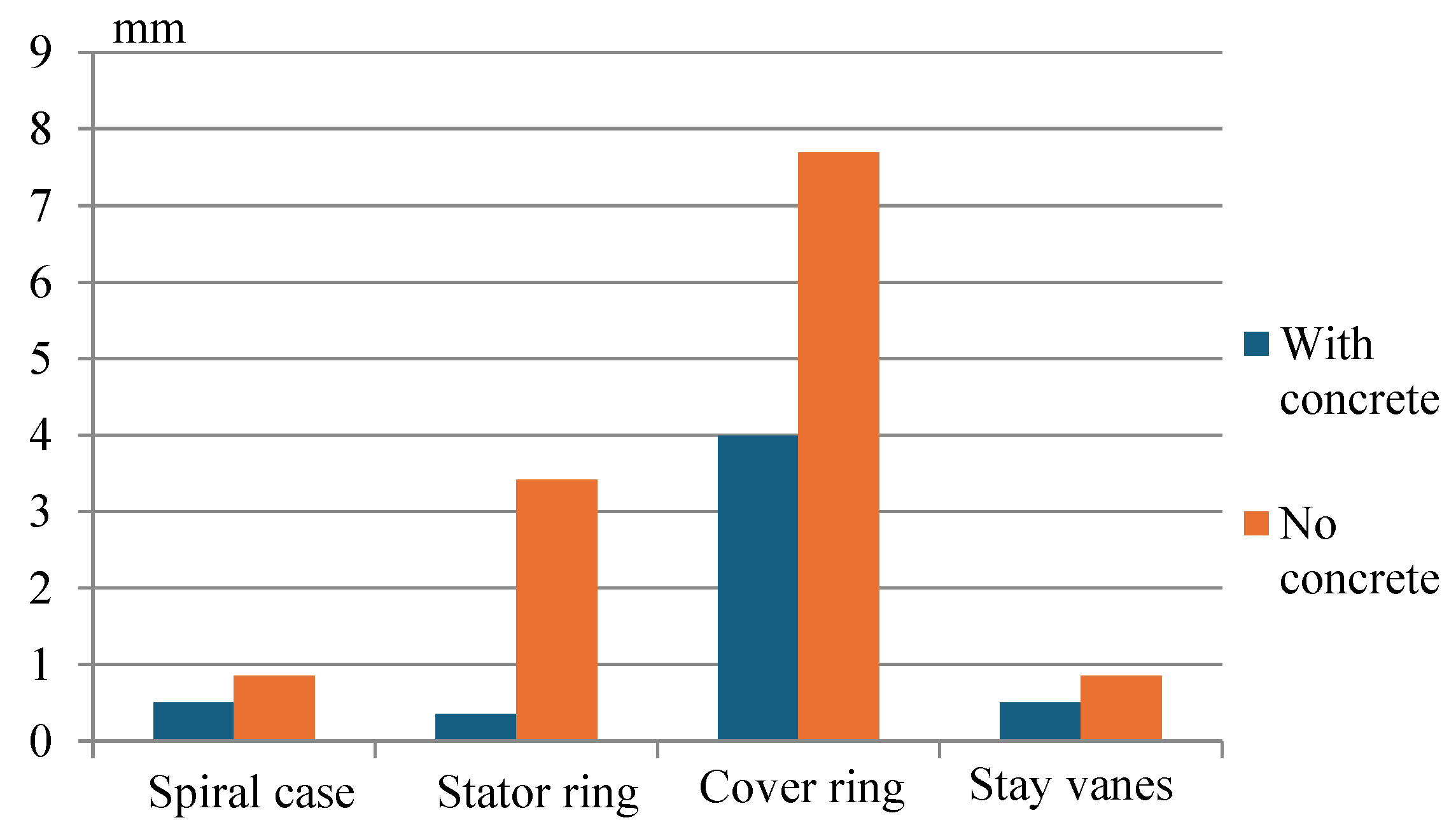
Both models – with and without concrete structure – could be compared as to outline the importance of the concrete structure and its possible influence on overall performance of the examined hydraulic assembly. This comparison is performed on the basis of three indicators, shown in previous chapter – stress, strain and displacement. It is shown as diagrams in Figure 12, Figure 13 and Figure 14.
5. Discussion
Some comments could be stated based on the results of the simulation and on diagrams above i.e.,:
- the influence of the concrete structure support over the maximal stress values is insignificant, as the structure is experiencing plastic deformations in both examined cases;
- the displacements are increased nearly twice, that is due to the decreased rigidity of the structure;
- the plastic strains are increased nearly 40%, leading to definitive possibility for crack initiation.
As it was said above for the A2 simulation (without concrete embedment) only the supporting basement of the turbine is considered without the surrounding concrete of the spiral case. This is because the fact that the gap between the spiral case and its surrounding concrete continuously increases. That is why the stresses in the supporting ring are as a result of the weight of the turbine on the foundation (Figure 10 a) while the stresses in the cover ring are negligible.
6. Conclusions
Based on the numerical experiments conducted, as well as of the consequential analysis the major conclusions for the reasons of the accident of the HA4 in the HEPS are:
- the gap between the concrete and the spiral case continuously increases as a result of the variable contact during operation in different modes and internal pressures which leads to destruction of the concrete (the same conclusion of the Chinese scientists, Figure 3 [25]);
- although the stresses and strains in the cover ring are admissible (Figures 8a, 9b, 10a and 11b) its total deformation (Figures 9a and 11a) are significant;
- the investigations A2 show that if the gap between the turbine and the concrete embedment is significant (no contact) the main loading as a result of the extremely high pressure is on the stay vanes (supporting columns);
- the stresses and strain simulation presented in Figures 8b, 9b, 10b and 11b prove the aforementioned conclusion that parts of the stay vanes are imposed on critical loading during the operational mode.
- it is proven that the contact surfaces between the support ring, the stay vanes (supporting columns) and the cover ring are the places with extremely high plastic stresses;
- concentration of unacceptable stresses in the cross sections of the stay vanes along the sections of the welding are observed;
- realization of the embedment method P (see chapter II) is not effective based on more than 100 years of experience for application of such structures, although some disadvantages could be observed with the other methods of embedment.
The investigations continue on the structure behavior in case of other turbine working conditions, as start stop regime, emergency situations, pumped regime, the effect of cavitation and other possible situations. Further investigations to be carried out on the cover ring, stay ring and supporting columns and possible new design solutions are to be proposed.
Author Contributions
Conceptualization, G.T. and K.K.; methodology, G.T., K.K. and Y.S.; software, B.Z.; validation, I.K. and Y.S.; formal analysis, G.T.; investigation, K.K. and B.Z.; resources, Y.S.; data curation, B.Z. and Y.S.; writing—original draft preparation, K.K.; writing—review and editing, G.T. and K.K.; visualization, Y.S. and B.Z.; supervision, I.K.; project administration, G.T. and I.K.; funding acquisition, I.K.; editing, consultation and review EZ. All authors have read and agreed to the published version of the manuscript.
Acknowledgments and Funding
This study is financed by the European Union-Next Generation EU, through the National Recovery and Resilience Plan of the Republic of Bulgaria, project № BG-RRP-2.004-0005 and by the project КП-06-Н67/8 „Development of a fluid-structural methodology for the study and modernization of HYDRAulic turbomachines, through the TECHnologies of virtual prototyping – HydraTech“.
Data Availability Statement
The data presented in this study are available on request from the corresponding author. The data are not publicly available due to relation to public funding specifics.
Declaration of Conflicts of Interest
The authors declare no conflict of interest. The funders had no role in the design of the study; in the collection, analyses, or interpretation of data; in the writing of the manuscript; or in the decision to publish the results.
References
- Javier, F.; Christian B., Aging of European power plant infrastructure as an opportunity to evolve towards sustainability. International Journal of Hydrogen Energy, 13 July 2017, Volume 42, Issue 28, 18081-18091.
- Kougias, I.; Aggidis, G.; Avellan, F.; Deniz, S.; Lundin, U.; Moro, A;. Muntean, S.; Novara, D.; Juan Ignacio Pérez-Díaz, Quaranta, E.; Schild, Ph.; Theodossiou ,N. Analysis of emerging technologies in the hydropower sector, Renewable and Sustainable Energy Reviews, 2019, Volume 113, 109257.
- Toufani, P.; Nadar, E.; Kocaman, A.S. Operational benefit of transforming cascade hydropower stations into pumped hydro energy storage systems, Journal of Energy Storage, 2022, Volume 51, 104444. [CrossRef]
- Punys, S.; Baublys, R.; Kasiulis, E.; Vaisvila, A.; Pelikan, B.; Steller, J. Assessment of renewable electricity generation by pumped storage power plants in EU Member State, Renewable and Sustainable Energy Reviews, 2013, Volume 26, 190-200. [CrossRef]
- Yang, J.; Robert, B.; Jackson, R.B. Opportunities and barriers to pumped-hydro energy storage in the United States, Renewable and Sustainable Energy Reviews, 2011, Volume 15, Issue 1, 839-844.
- Manikas, K.; Skroufouta, S.; Baltas, E. Simulation and evaluation of pumped hydropower storage (PHPS) system at Kastraki reservoir, Renewable Energy, 2024, Volume 222, 119888. [CrossRef]
- Amirante, R.; Cassone, E.; Distaso, E. Tamburrano, P. Overview on recent developments in energy storage: Mechanical, electrochemical and hydrogen technologies, Energy Conversion and Management, 2017, Volume 132, 372-387. [CrossRef]
- Kucukali, S.; Finding the most suitable existing hydropower reservoirs for the development of pumped-storage schemes: An integrated approach, Renewable and Sustainable Energy Reviews, 2014, Volume 37, 502-508. [CrossRef]
- Wilson. I.A.G.; Barbour, E.; Ketelaer, T.; Kuckshinrichs, W. An analysis of storage revenues from the time-shifting of electrical energy in Germany and Great Britain from 2010 to 2016, Journal of Energy Storage, 2018, Volume 17, 446-456. [CrossRef]
- Favrel, A.; Müller, A.; Landry, C.; Yamamoto, K.; Avellan, F. Study of the Vortex-Induced Pressure Excitation Source in a Francis Turbine Draft Tube by Particle Image Velocimetry, Exp. Fluids, 2015, Volume 56(12), 215. [CrossRef]
- Favrel, A.; Müller, A.; Landry, C.; Yamamoto, K.; Avellan, F. LDV Survey of Cavitation and Resonance Effect on the Precessing Vortex Rope Dynamics in the Draft Tube of Francis Turbines,Exp. Fluids, 2016, Exp. Fluids, Volume 57(11), 168. [CrossRef]
- Alligné, S., Nicolet, C., Tsujimoto, Y., and Avellan, F., Cavitation Surge Modelling in Francis Turbine Draft Tube, J. Hydraul. Res., 2014, Volume 52(3), 1–13. [CrossRef]
- Müller, A.; Favrel, A.; Landry, C.; Avellan, F. Fluid-Structure Interaction Mechanisms Leading to Dangerous Power Swings in Francis Turbines at Full Load, J. Fluids Struct.,2017, Volume 69, 56–71. [CrossRef]
- Panov, L.; Chirkov, D.; Cherny, S.; Pylev, I.; Sotnikov, A. Numerical Simulation of Steady Cavitating Flow of Viscous Fluid in a Francis Hydroturbine, Thermophys. Aeromech, 2012, Volume 19(3), 415–427. [CrossRef]
- Susan-Resiga, R.; Ciocan, G.; Anton, I.; Avellan, F. Analysis of the Swirling Flow Downstream a Francis Turbine Runner,” ASME J. Fluids Eng., 2006, Volume 128(1), 177–189. [CrossRef]
- Rudolf, P.; and Štefan, D. Decomposition of the Swirling Flow Field Downstream of Francis Turbine Runner, IOP Conf. Ser. Earth Environ. Sci., Volume 15(6) 2012, 062008. [CrossRef]
- Dörfler, P.; Keller, M.; Braun; O. Francis Full-Load Surge Mechanism Identified by Unsteady 2-Phase CFD, IOP Conf. Ser. Earth Environ. Sci., Volume 12(1), 2010, 012026. [CrossRef]
- Mössinger, P.; Conrad, P.; Jung, A. Transient Two-Phase CFD Simulation of Overload Pressure Pulsation in a Prototype Sized Francis Turbine Considering the Waterway Dynamics,” IOP Conf. Ser. Earth Environ. Sci., Volume 22(3), 2014, 032033. [CrossRef]
- Chirkov, D.; Panov, L.; Cherny, S.; Pylev, I. Numerical Simulation of Full Load Surge in Francis Turbines Based on Three-Dimensional Cavitating Flow Model, IOP Conf. Ser. Earth Environ. Sci., Volume 22(3), 2014, 032036. [CrossRef]
- Wack, J; Riedelbauch, S. Numerical Simulations of the Cavitation Phenomena in a Francis Turbine at Deep Part Load Conditions, J. Phys. Conf. Ser,2015, Volume 656, 012074. [CrossRef]
- Trivedi, C.; and Cervantes, M.J. State of the Art in Numerical Simulation of High Head Francis Turbines, Renewable Energy Environ. Sustainability, Volume 1, 2016, 20. [CrossRef]
- Yasuda, M.; Watanabe, S. How to Avoid Severe Incidents at Hydropower Plants, International Journal of Fluid Machinery and Systems, 2017, Volume 10, No. 3, 296-306.
- Price, J. W.H.; The failure of the Dartmouth turbine casing, International Journal of Pressure Vessels and Piping, 1998, Volume 75, No 7, 559–566.
- https://www.scribd.com/document/623320017/EP0786594B2 Francis turbine assembly, Kawasaki-shi, Kanagawa-ken 210-8572, European patent EP 0 786 594 B2, Priority: 23.01.1996, Japan patent JP 946696.
- Gao, X.; Fu, D.; Wu, H., Embedment of Steel Spiral Cases in Concrete: Lessons from a Structural Deformation Accident in China. Applied Science, 2022, Volume 12, 8395. [CrossRef]
- Rabbat, B.G.; Russell, H.G. Friction Coefficient of Steel on Concrete or Grout. J. Struct. Eng. 1985, Volume 111, 505–515. [CrossRef]
- Baltay, P.; Gjelsvik, A. Coefficient of Friction for Steel on Concrete at High Normal Stress. J. Mater. Civ. Eng. 1990, 2, 46–49. [CrossRef]
- Tian, Z..; Zhang, Y.; Ma, Z. et al. Effect of concrete cracks on dynamic characteristics of powerhouse for giant-scale hydrostation. Trans. Tianjin Univ., 2008, Volume 14, 307–312. [CrossRef]
- Yu, Y.; Zhang, Q.L.; Wu, H.G. Reinforcement calculation for spiral case embedded with cushion layer of hydropower station. Tianjin Daxue Xuebao (Ziran Kexue yu Gongcheng Jishu Ban), J. Tianjin Univ. Sci. Technol, 2009, Volume 42, 673–677.
- Xu, X.; Li, M.; Ma, Z; Zhang, H.; He, P. Simulation and analysis of the constant internal pressure spiral case with non-uniform gap. Shuili Fadian Xuebao, J. Hydroelectr. Eng, 2009, Volume 28, 75–80.
- Ma, Z.; Zhang, C. Static and dynamic damage analysis of mass concrete in hydropower house of Three Gorges Project. Trans. Tianjin Univ, 2010, Volume 16, 433–440. [CrossRef]
- Panda, S.; Jena J.; Basa, B. Stress analysis around spiral casing of Francis turbine of a Hydel power house by finite element method. In Proceedings of International Conference on Structural Engineering and Mechanics, Rourkela, India, December 20-22, 2013.
- Chen, W.; Xian, L. Analysis and treatment of a raising deformation accident of the No.9 spiral case structure in Xiluodu hydroelectric power plant, Shaanxi Water Resour., 2012, Volume 05, 41–43.
- Zhang, Q.-L.; Wu, H.-G. Advance in research and application of spiral case structure with a membrane in hydroelectric power plant. Shuili Xuebao, J. Hydraul. Eng, 2012, Volume 43, 869–876.
- Zhang, Q.L.; Wu, H.G. Effect of compressible membrane’s nonlinear stress-strain behavior on spiral case structure, Struct. Eng. Mech., 2012, Volume 42, 73–93. [CrossRef]
- Zhang, Q.L.; Wu, H.G. Using softened contact relationship describing compressible membrane in FEA of spiral case structure, 2013, Volume 13, 506–517. [CrossRef]
- Zhang, Q.L; Wu, H.G. Sliding behaviour of steel liners on surrounding concrete in c-cross-sections of spiral case structures. Struct. Eng. Int, 2016, Volume 26, 333–340. [CrossRef]
- Zhang, Q.L.; Wu, H.G. Embedment of steel spiral cases in concrete: China’s experience, Renew. Sustain. Energy Rev, 2017, Volume 72, 1271–1281. [CrossRef]
- Wu, H.; Shen, Y.; Jiang, K.; Shi, J. Structural Analysis of the Embedded Spiral Case in the Three Gorges Hydropower Station, Practice Periodical on Structural Design and Construction, 2012, Volume 17, No. 2, , 41-47. [CrossRef]
- Guo, T.; Zhang, L.; Li, S. Research on three-dimensional simulation algorithm of preloaded filling spiral case with non-uniform gap, Shuili Xuebao, J. Hydraul. Eng, 2015, Volume 46, 1434–1443.
- Zhang, Q.-L.; Hu, C.; Hu, L.; Wu, H.-G. Compression-Resilience Responses of Commonly Used Membrane Materials in Spiral Case Structures of Hydroelectric Power Plants: Experimental Investigation, J. Mater. Civ. Eng, 2018, Volime 30, 06018005. [CrossRef]
- Zhimin Z.; Hegao W.; Changzheng S.; Qiling Z.; Kai S; Lei H. Numerical modeling of preloaded filling spiral case structure, Latin American Journal of Solids and Structures, 2018, Volume 15, No. 8, 110. [CrossRef]
- Yongfeng, Q.; Qin C.; Yaqi, G.; Zhiqiang X. Optimization analysis of giant spiral case with combined embedding method, IOP Conference Series Earth and Environmental Science, September, 2019, Volume 304, No. 3, 032064.
- Guo, T.; Zhang, L.; Li, S. Influences of boundary conditions on the initial gap of preloading water-filled spiral case. Nongye Gongcheng Xuebao/Trans. Chin. Soc. Agric. Eng. 2020, Volume 36, 40–47.
- Birtarescu, E.; Constantin Câmpian, V.; Nedelcu, N. Strength Calculations Performed on the Spiral Casing of a Francis Turbine Operating in Secondary Control Regime, Scientific Bulletin Mechanical Engineering, 2021, Series D, Volume 83, No 2.
- Gao, X.; Wu, H.; Fu, D. Effect of Temporary Internal Water Pressure on Structural Performance of Spiral Case Structure in Pumped-Storage Power Plants. Energies, 2022, Volume 15, 2463. [CrossRef]
- Wenjie, X.; Gang W.; Zhenyue, M; Fei. K. Analysis of the Joint Bearing Capacity of Composite Cushion-Spiral Case Structures for Hydropower Stations Considering the Damage Mechanisms of Surrounding Concrete, Water, 2024, Volume 16, No. 1, 112.
- Todorov, G. D.; Kamberov, K. H. Black box/white box hybrid method for virtual prototyping validation of multiphysics simulations and testing. IOP Conf. Ser.: Mat. Sci. and Eng., 2020, No. 1, 878. [CrossRef]
- Malakov, I.; Zv, V.; Tzeaharinonov, V. Size Ranges Optimization. Proc. Eng., 2015, 791-800.
- Vacheva, G.; Hinov, N. Modeling and simulation of hybrid electric vehicles, Proceedings of the 46th Int. Conf. on App. of Math. in Eng. and Econ., 2021, Sozopol.
Figure 1.
Simple design scheme of a Francis turbine.
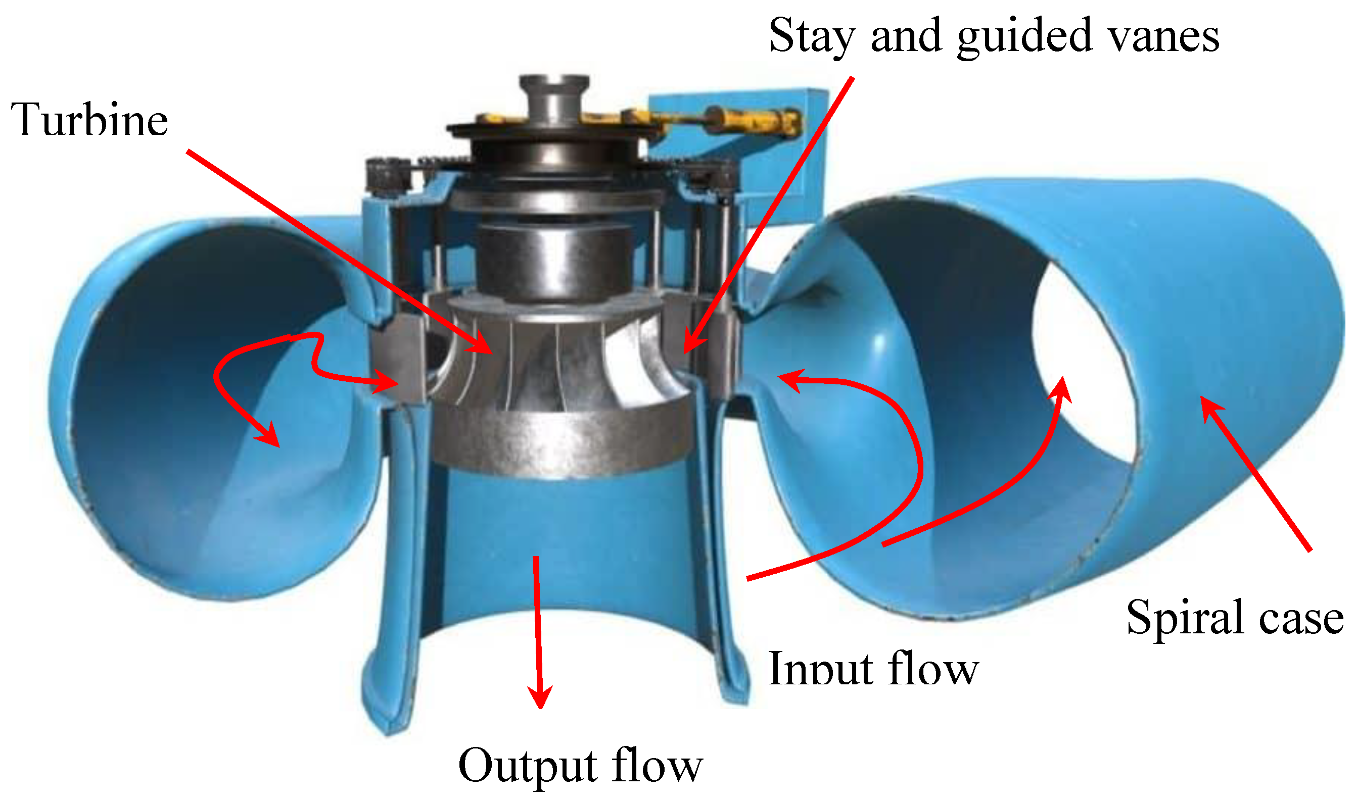
Figure 2.
Embedment of the spiral case in concrete.
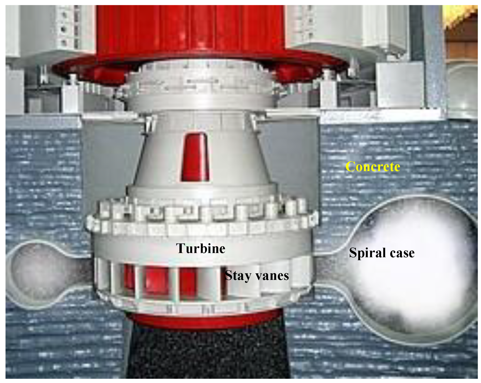
Figure 3.
Erosion and destructions of the basement concrete [25].
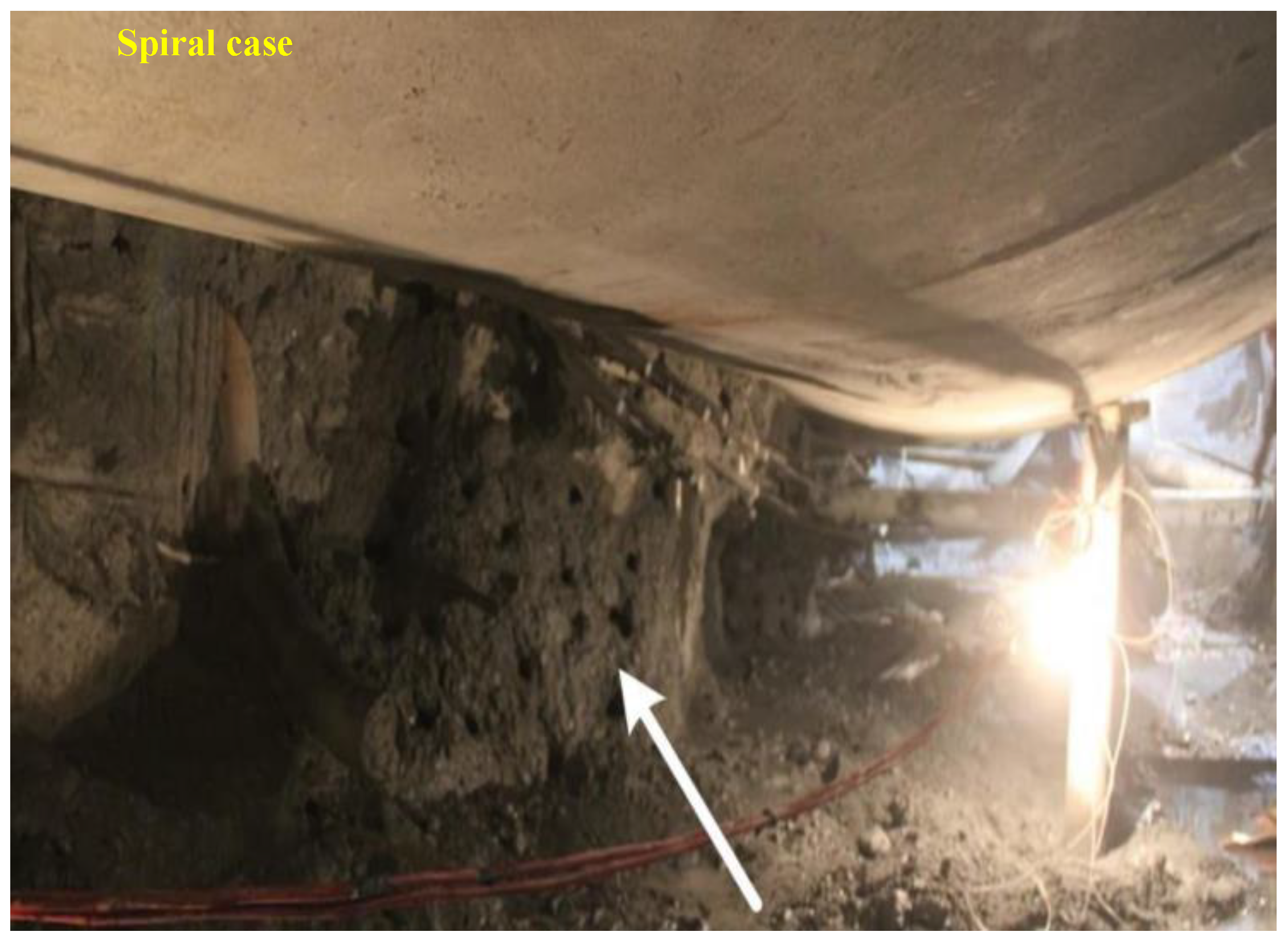
Figure 5.
HA4 Francis turbine: (a) 3D model of spiral case, cover ring and stay vanes; (b) examined static components of the hydraulic units.
Figure 5.
HA4 Francis turbine: (a) 3D model of spiral case, cover ring and stay vanes; (b) examined static components of the hydraulic units.
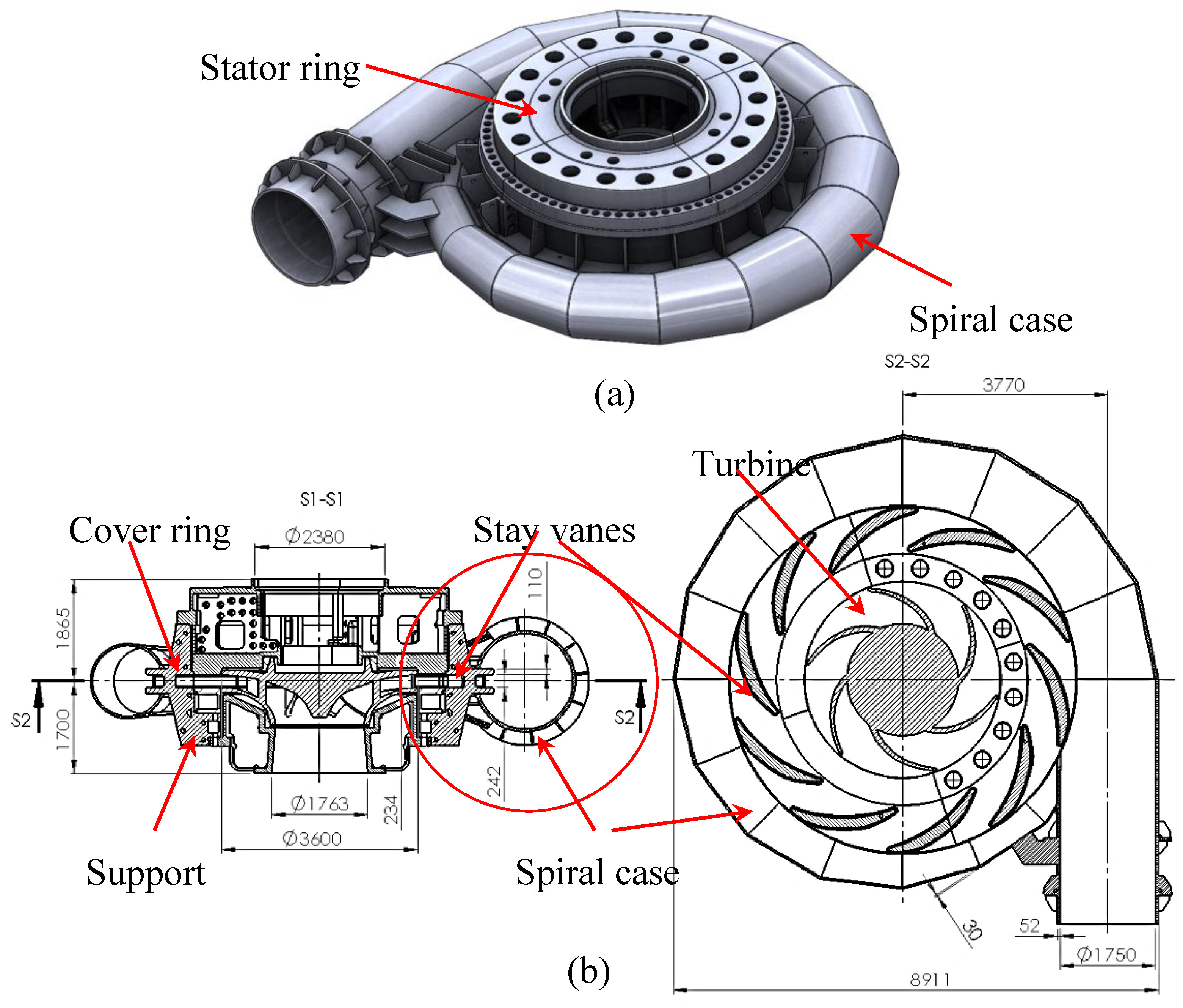
Figure 6.
The embedment of the spiral case with enforced concrete.
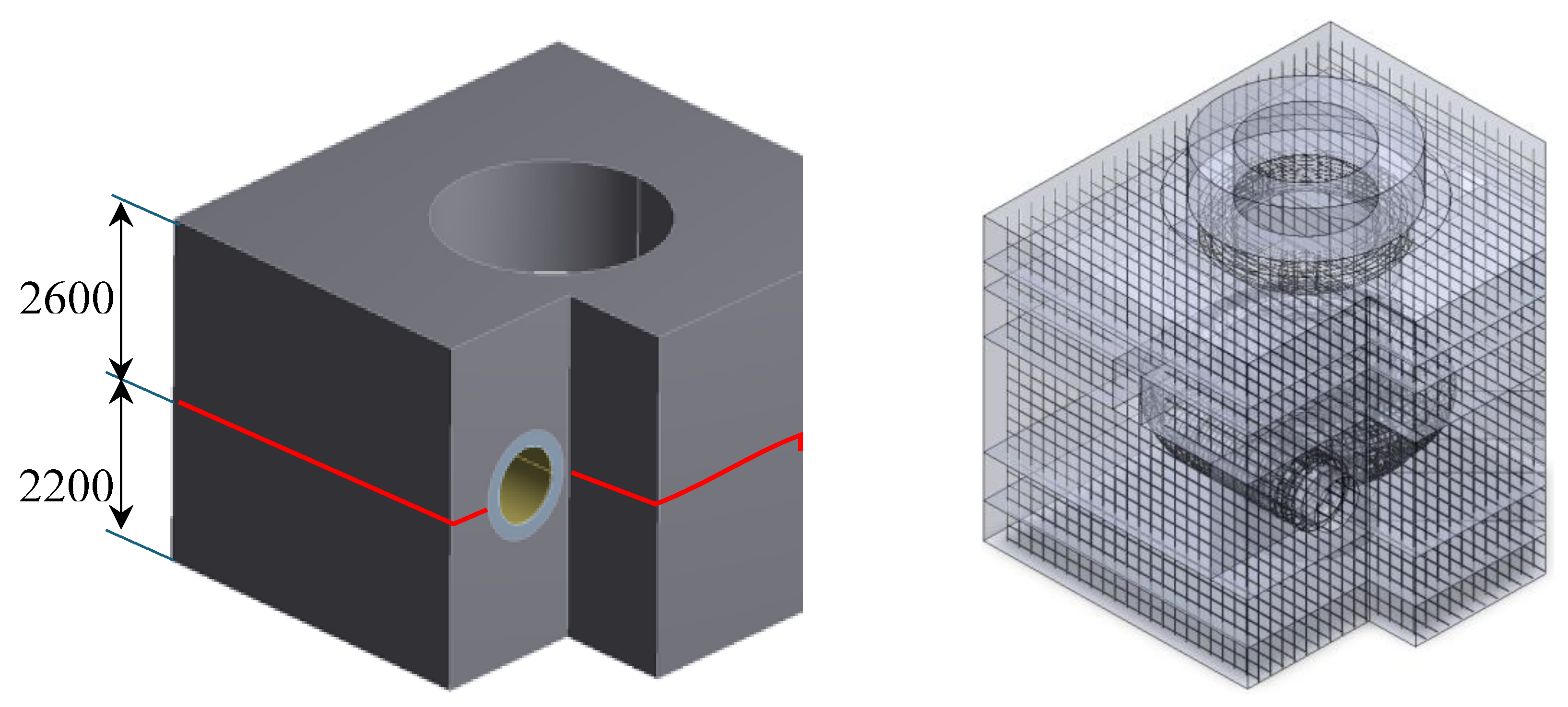
Figure 7.
Generated mesh for the model (a, b) with concrete and local (c, d) sectional zoom of the basement and the stay vanes mesh.
Figure 7.
Generated mesh for the model (a, b) with concrete and local (c, d) sectional zoom of the basement and the stay vanes mesh.
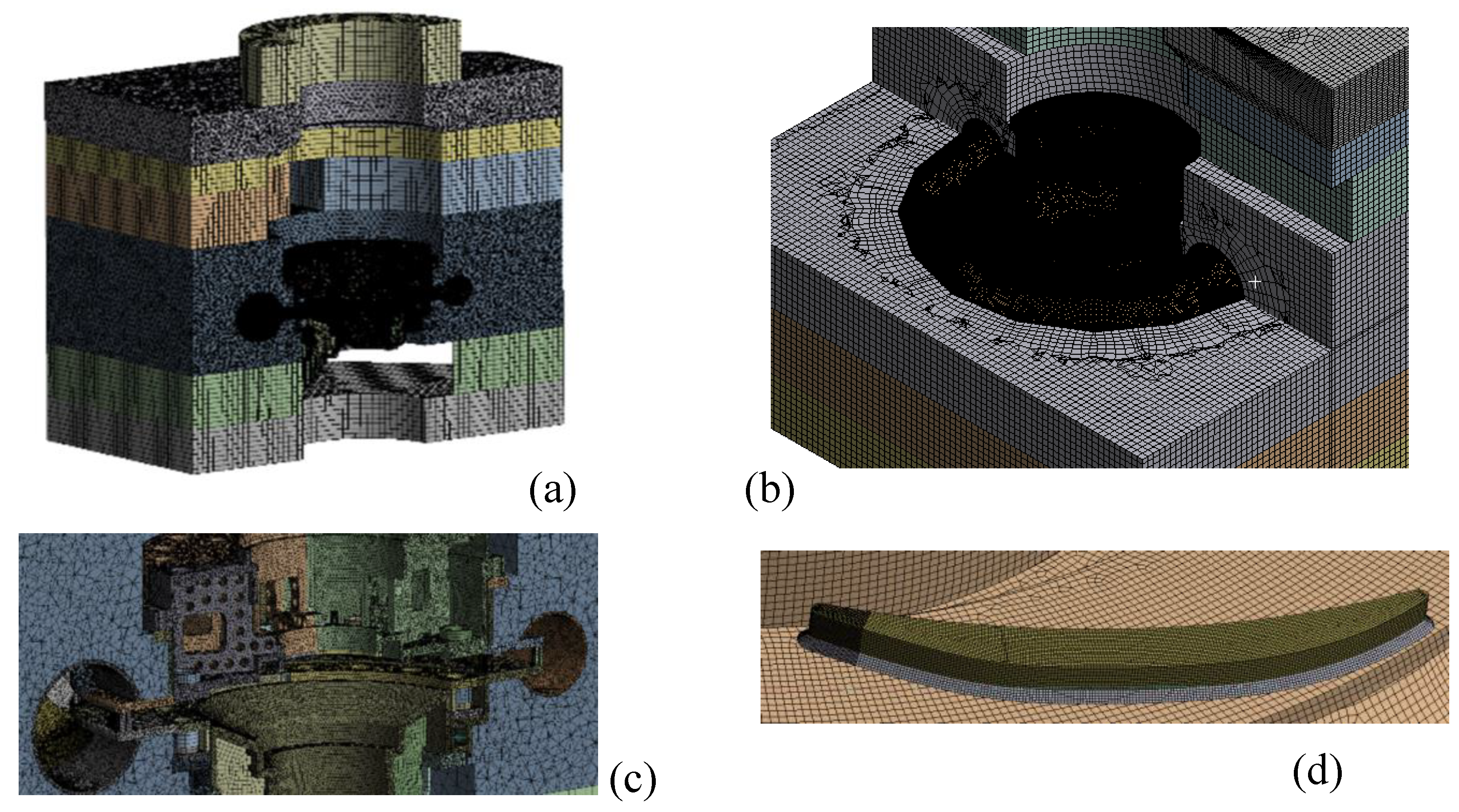
Figure 8.
A1: Equivalent (von Mises) stress distribution MPaм; (a) segment cross sectional view (see Figure 5 b); (b) local section of a stay vane.
Figure 8.
A1: Equivalent (von Mises) stress distribution MPaм; (a) segment cross sectional view (see Figure 5 b); (b) local section of a stay vane.
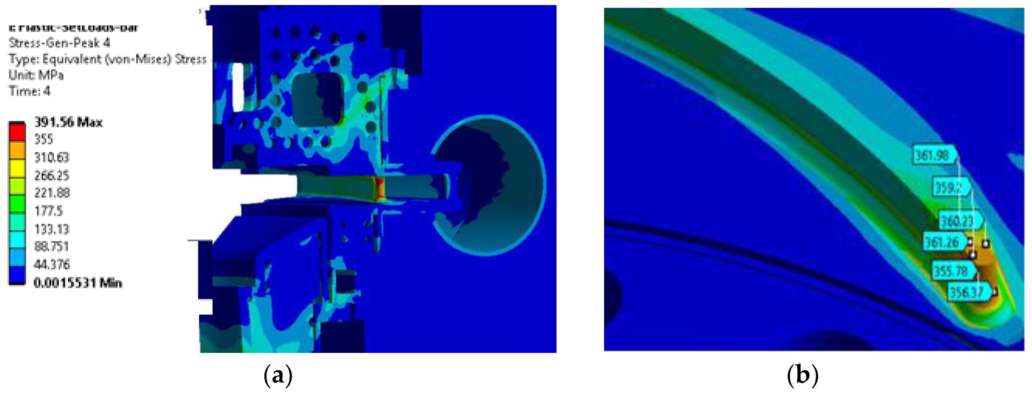
Figure 9.
A1: Displacement and strain distributions; (a) total deformation, mm; (b) plastic strains mm/mm.
Figure 9.
A1: Displacement and strain distributions; (a) total deformation, mm; (b) plastic strains mm/mm.
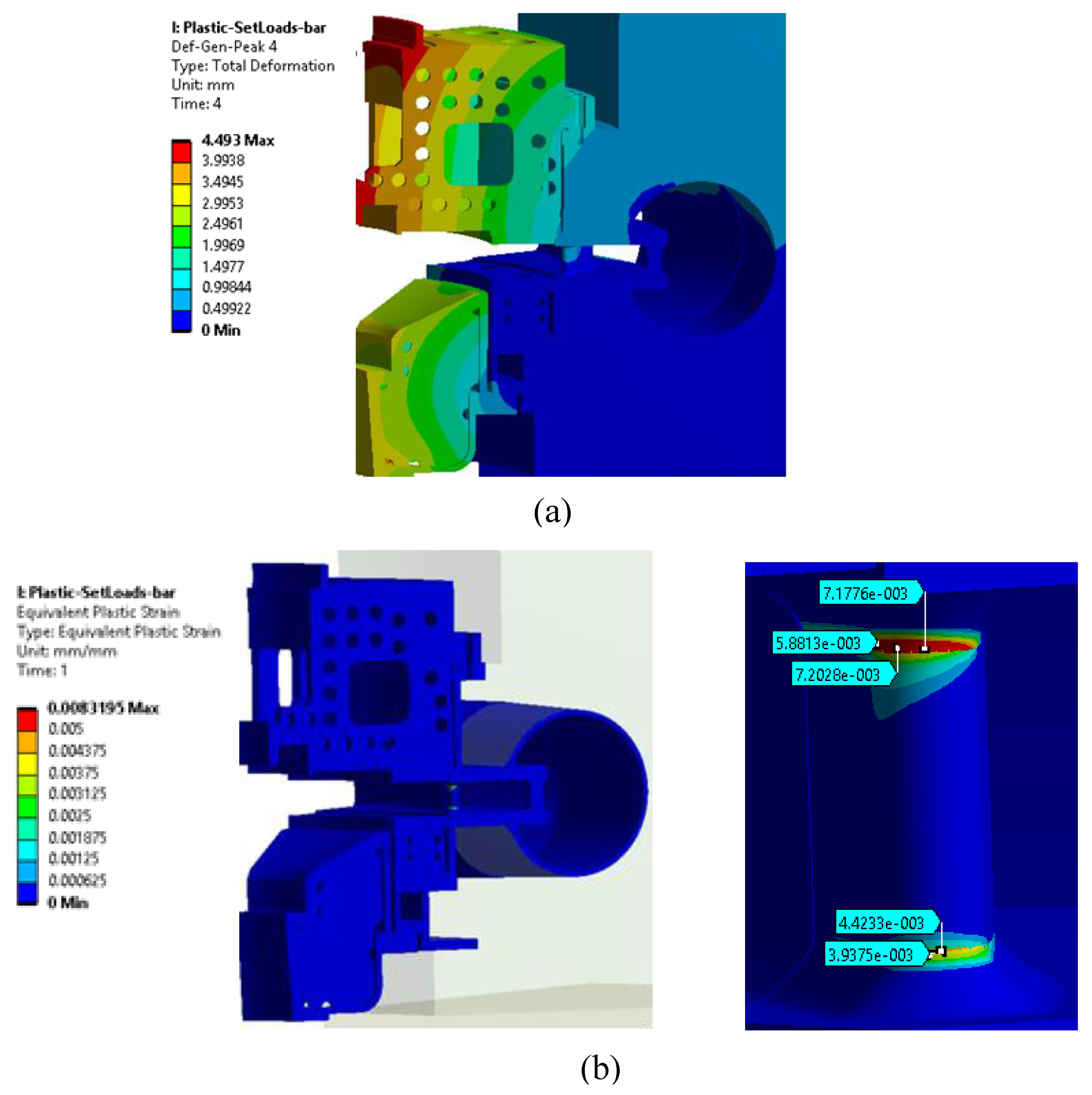
Figure 10.
A2: Equivalent (von Mises) stress distribution, MPa; (a) segment cross sectional view; (b) local section of a stay vane.
Figure 10.
A2: Equivalent (von Mises) stress distribution, MPa; (a) segment cross sectional view; (b) local section of a stay vane.
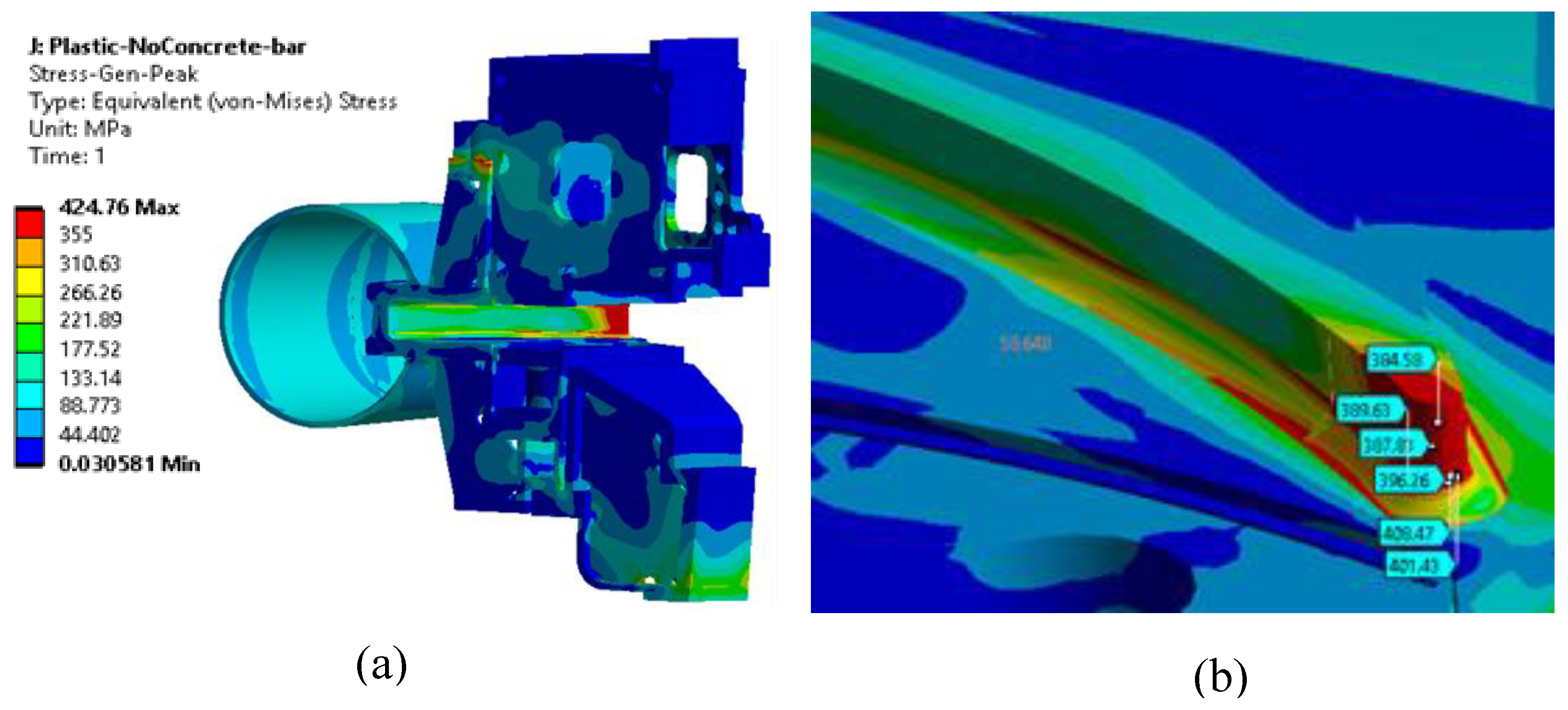
Figure 11.
A2: Displacement and strain distributions; (a) total deformation, mm; (b) plastic strains mm/mm.
Figure 11.
A2: Displacement and strain distributions; (a) total deformation, mm; (b) plastic strains mm/mm.
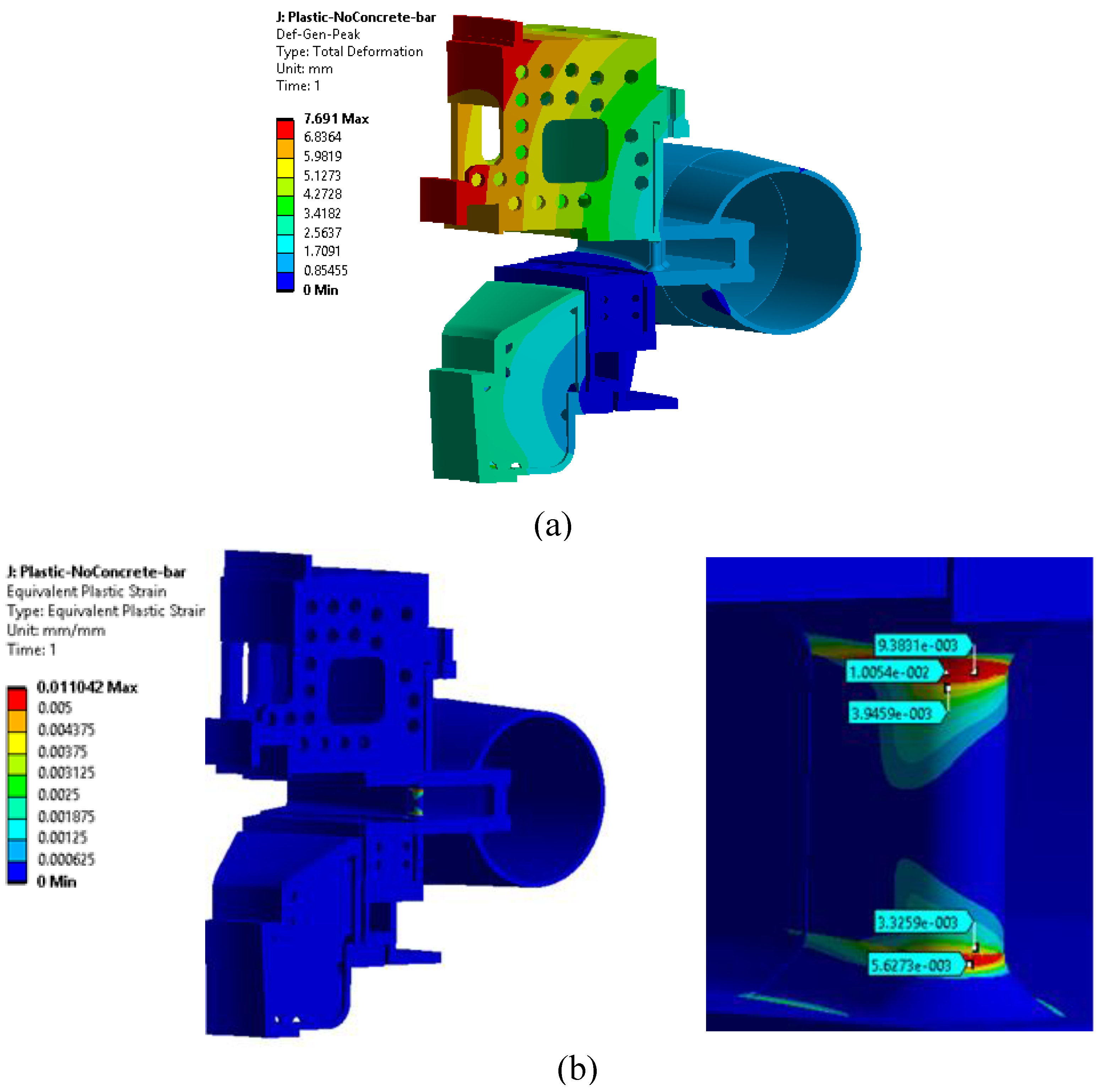
Figure 12.
Equivalent (von Mises) stresses distribution, MPa.

Figure 13.
Plastic strains mm/mm.
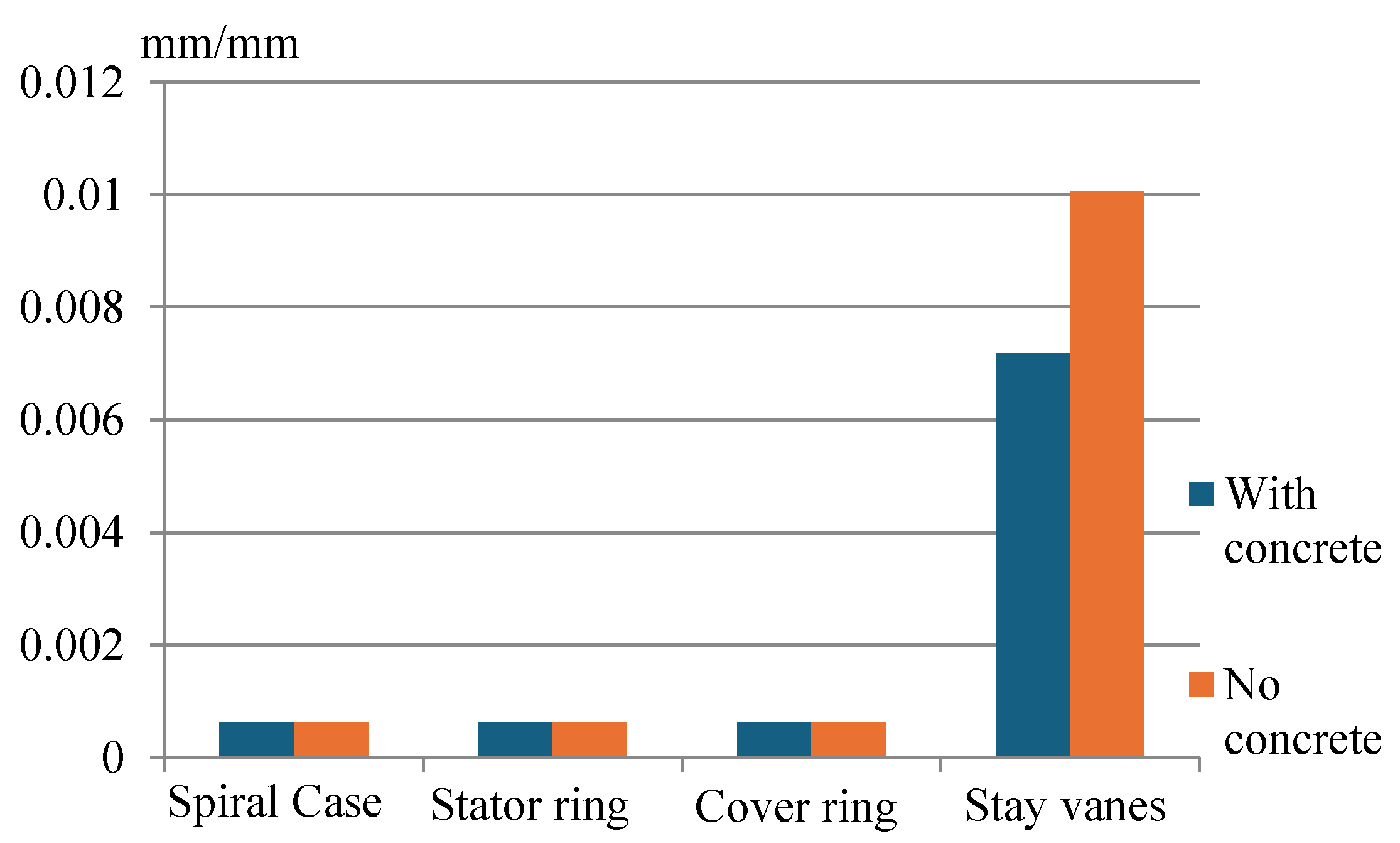
Figure 14.
Total deformation, mm.
Disclaimer/Publisher’s Note: The statements, opinions and data contained in all publications are solely those of the individual author(s) and contributor(s) and not of MDPI and/or the editor(s). MDPI and/or the editor(s) disclaim responsibility for any injury to people or property resulting from any ideas, methods, instructions or products referred to in the content. |
© 2024 by the authors. Licensee MDPI, Basel, Switzerland. This article is an open access article distributed under the terms and conditions of the Creative Commons Attribution (CC BY) license (http://creativecommons.org/licenses/by/4.0/).
Copyright: This open access article is published under a Creative Commons CC BY 4.0 license, which permit the free download, distribution, and reuse, provided that the author and preprint are cited in any reuse.


