Submitted:
10 June 2024
Posted:
12 June 2024
You are already at the latest version
Abstract
The critical systems, which the failure and malfunction may result in human, environment and financial severe damages, are essential components in various sectors and particularly in energy domains. Although unwished, integration error problems in supervision of critical systems occurs, incurring significant expenses because of operator’s subjective analysis and on hardware topology failures. In this work, a malleable model design approach is proposed to formulate and solve the integration error problem in the critical systems supervision in terms of reliability. A real Hybrid Power Plant (HPP) case is considered as a requirement for a study case with simulated data. A method framework with informal approach (C4 diagram) and formal approach (Hierarchical Coloured Petri Nets) in radial spectrum is applied to the HPP supervision design. Using formal methods, a formulation and solution to this problem through structured, scalable and compact mathematical representations are possible. This malleable model intends to guarantee functional correctness and then reliability of the plant supervision system based on system software architecture. Outcomes suggest corroboration that the malleable model is appropriate for energy domain, and can be used for other types of critical systems, bringing all the benefits of this methodology to the context in which it will be applied.
Keywords:
Critical Systems
; Automation System
; Supervision
; Integration
; Reliability
; Malleable Model
; Formal Languages
; Hybrid Power Plant
1. Introduction
Critical systems engineering focuses on blending human skills with Information Technology (IT)-enabled technical systems to achieve societal and industrial objectives, since the failure and malfunction of these systems may result in human, environment and financial severe damages [9,27]. In essence, critical systems are crucial technological backbones that require rigorous design, development and testing processes to ensure their correct operation. In this context, the supervision of these systems has a fundamental role as it provides the needed information, in order to make decisions correctly and timely.
The critical systems are essential components in various sectors like aerospace, banking, manufacturing, and particularly, in energy domains. For example, Hybrid Power Plant (HPP) is a kind of critical system, which can be understood as a physically coupled power-generating facility that converts primary energy (for example, wind, photovoltaic and storage assets) into electrical energy. Typically, a HPP is composed by two or more types of Renewable Energy Source (RES) operating as an integrated system, and is considered as an interesting option to meet the high load demands for electrical energy in an intelligent way.
The operation of HPP is considered complex due to its number of elements, such as assets, transducers, local controllers and data servers which interact each other or with its environment, having distinct properties that arise from these interactions [21]. Besides, the occurrence of uncertainties during the operation related to economic, political, technical, regulatory, environmental, resource availability, social and climate aspects can result in serious problems of generation stability and power quality [8]. Therefore, adequate integration in HPP automation system is mandatory to guarantee the plant supervision and control.
Although unwished, integration error problems in supervision of critical systems occurs. Reports validate that inadequate handling by an unqualified operator leads to incidents in the Supervisory Control and Data Acquisition (SCADA) system, as seen in the Enbridge Incorporated pipeline rupture on July 25, 2010 [2]. Research findings suggest that 30% of all incidents on SCADA systems are attributable to internal staff [5]. Moreover, essential authentic data for evaluating threats posed by operators errors in the SCADA system are not accessible to the public due to privacy concerns, making this type of problem difficult to detect.
Thus, a way to address this type of problem is through reliability studies 1. In the energy domain, reliability is one of the most significant properties of power plants, where problems related to it can have a negative impact on energy supply and security. Currently, traditional reliability modeling approaches such as Reliability Block Diagram (RBD), Fault Tree Analysis (FTA) and Markov Analysis (MA) are widely employed in energy system reliability study and evaluation [18,20].
However, these approaches incorporate subjective analysis because they are typically performed manually by reliability engineers, whose the skills and experience play a considerable role in determining functional correctness 2 of the system. Besides, these methods are dependent on hardware topology whose different types of configuration (simple cascading, redundant cascading, ring, star and hybrid) change the reliability rate and make it difficult to flexibly adjust the system. As the integration and complexity of current energy system develop, reliability engineers find it increasingly challenging to understand the actual behavior of the systems, being more likely to contain errors in obtaining results, which reduces the reliability assessment’s accuracy.
In this context, a critical system must be extremely reliable and maintain this propriety as it evolves, without incurring exorbitant expenditures. Due to this, there is a need to build a solution proposal that does not depend on the operator’s subjectivity nor on the hardware topology, in order to guarantee functional correctness and reliability during the supervision. Thus, a solution based on system software architecture is a promising trend of research in software engineering, in which make possible that engineers work with logical diagrams and casual relationships in different spectra using malleable modeling concept [13].
The ideal degrees of abstraction, strictness and granularity for a malleable model might be achieved with an adaptable blend of informal diagramming and formal modeling. However, this tendency does not indicate a methodological approach for complete implementation of a malleable model, as it deals with this topic from informal 3 to formal 4 perspective and vice versa, without gathering the best aspects of all of spectra of integrated way and applied for supervision system development.
In this work, a malleable model design solution is proposed to formulate and solve the integration error problem in the critical systems supervision, considering all automation layers of a HPP real-unit test case. It is used C4 diagram as an informal approach and also a logical modeling with Hierarchical Coloured Petri Nets (HCPN) as a formal approach powerful tool in the plant supervision design to present the proposed methodology. To do so, the remainder of this work is organized as follows. In Section 2, the theoretical reference is described. In Section 3, the methodology is detailed. In Section 4, a case study is explained. In Section 5 and Section 6, main discussions and conclusions are presented.
2. Theoretical Reference
Critical system requires a high level of reliability to ensure safety and efficiency. Research in the area of critical system reliability emphasizes the importance of hardware topology and operator skill to make decisions. However, there is a growing concern about the lack of studies addressing the reliability from a software perspective of these complex systems with researchers looking to work on domain-specific problems to improve reliability metrics and approaches. Overall, this work highlights the crucial role of software in ensuring the reliability, functionality and safety of various critical systems.
Software architecture 5 overview is used at the beginning of project life cycle to demonstrate logical and physical data flow of the critical system under development. Specifically, software architecture is subject to changes produced by operational decisions taken along the overall the project. From this perspective, a malleable combination of informal diagramming and formal modeling would allow right levels of abstraction, strictness and granularity for the supervisory system. Thus, malleable model is presented in SubSection 2.1.
2.1. Malleable Model
According to Jongeling and Ciccozzi [13], malleable modeling is a flexible and bidirectional interface between static and dynamics behaviors of the software system, regardless of applied technology. Malleable models allow engineers to benefit both from the advantages of informal diagramming and from the benefits of formal modeling simultaneously, while also supporting detail level adjustment for specific uses.
In the malleable modeling, there is a fluid movement along and across the two spectra shown in Figure 1: horizontal spectrum, which goes from informal to formal modeling; and the vertical spectrum, that shows the level of diagram abstraction, ranging from showing less to more detail.
As the information from critical system to be supervised is processed between different subsystems and operators, defining an approach based on componentization help to design the automation software architecture prior to implementation and deployment. In this sense, C4 diagram informal approach is described in SubSection 2.1.1.
2.1.1. C4 Diagram Informal Approach
By definition, C4 diagram (Context, Container, Components, Code) is built upon traditional UML [14,22] based diagramming process. This model is an UML simplified version to help software development teams to describe and communicate software architecture, both during up-front design sessions and when retrospectively documenting an existing codebase [3].
A generic C4 diagram is composed by four levels of architecture diagrams, named as:
- Level 1 (Software system context diagram): high level, referring to the key elements definition of the system context under consideration;
- Level 2 (Container diagram): intermediate level with description of the functioning and relationship among subsystems;
- Level 3 (Components diagram): intermediate level with abstractions of the needed internal components for each container;
- Level 4 (Code diagram): lowest level, referring to the diagrams coding described in the previous levels, using appropriate language close to the actual implementation.
In order to illustrate the link among these levels, a C4 diagram example is shown in Figure 2. In this diagram, the detail increases by level and creates the concept of abstraction, where the main idea is to expand the details as the level gets higher.
In Level 1, software system which is under development is shown. In this level, the way the software system relates to the world in terms of the people who use it and other software systems which it interacts with is also considered. In Level 2, the main diagram is indicated. Depending on the project, this diagram can be the first one to be developed. It has the capacity of expanding and collapsing its contents to reveal its inner workings and components. In Level 3, an internal element of the container is disclosed after unpacking. This diagram should map container abstractions, exhibiting components that make up the container with not much detail about how they work. In Level 4, as the developer unscrambles the component diagram, the coding of elements inside the component diagram will be expressed [4].
Although Level 4 can be considered optional in C4 diagram, integration of dynamics modeling in automation software architecture can be made possible by the malleable models application. By modeling parts of the data from the informal diagrams, this information becomes accessible for understanding of the automation system requirements and definition of new operational strategies. Therefore, the use of a formal approach is interesting for creating models in this circumstance. To do so, Hierarchical Coloured Petri Nets were chosen as the formal approach due to the features described in SubSection 2.1.2.
2.1.2. Basic Principles of Hierarchical Coloured Petri Nets Formal Approach
Coloured Petri Nets (CPN) are a formal method with graphical modeling language to specify concurrent systems, combining control structures described by Petri Nets and data manipulation executed by programming language [10,11]. A representation of the basic graphical elements of a CPN and their characteristics is shown in Figure 3.
In this figure, a place is represented by a circle with initial marking (INITIAL MARKING NAMED), place data type (TYPE OF PLACE) and an identification (NAME); arc is constituted by an arrow and an expression (EXPRESSION) which is an expression that evaluates to a multi-set 6 or a single element; and transition is defined for a rectangle with a guard ([ ]) which is boolean expression that evaluates to true or false, a delay expression (@+) which must be a positive integer and code segments (input(); 7 output(); 8 action(); 9).
A CPN has two types of nodes, places and transitions, with arcs connecting them. Since arcs cannot connect nodes of the same type directly, they must connect place nodes to transition nodes and vice versa, being a network bipartite. The input places for a transition are all those places that have an arc directed from the place to the transition; whereas the output places for a transition are all those places that have an arc directed from the transition to the place.
Any distribution of tokens 10 over the places will represent a configuration of the net called as marking. The initial marking is determined by evaluating the initialization expressions. In an abstract sense related to a CPN diagram, a transition of a CPN may fire if it is enabled, i.e., there are sufficient tokens in all of its input places. When the transition fires, it consumes the required input tokens and creates tokens in its output places, according to the arc expression. A firing is a single uninterruptible step. A CPN changes from one state to another state when a transition “fires”. The marking of each place is a multi-set over the colour set 11 attached to the place. Multi-sets are needed to allow two or more tokens to have identical token colours 12.
By formal definition [10,11], a CPN is given by a 9-tuple (, P, T, A, N, C, G, E, I) which satisfies the following properties:
- is a finite set of non-empty colour sets (types).
- P is the finite set of all places.
- T is the finite set of all transitions.
- A is the finite set of all arcs such that P ∩ T = P ∩ A = T ∩ A = ∅
- N is the node function such that N: A → P × T ∪ T × P
- C is the colour function such that C: P→
- E is the arc expression function such that E: A→ Expr and ∀ a ∈A : [ Type(E(a)) = C(p(a))MS 15∧ Type(Var(E(a))) ⊆], where p(a) is the place of N(a);
- I is the initialization function such that I: P→ Expr and ∀ p ∈P : [ Type(I(p)) = C(p)MS].
In CPN, the current marking of a given place is represented by a small circle, with an integer indicating how many tokens exists, and a text string next to the circle, with a multi-set showing what the individual token colours are, and which coefficients they have. By convention, the circle and the text string for places which have no tokens are omitted. For a given place, all tokens must have colours that belong to a specified type, and thus, coloured tokens can be distinguished from each other. From declarations, it can be seen what the colour sets are. The declarations use a language called CPN ML [23].
Allowing more complex markings also means that the moves in the PN become more complex. To describe this more complex situation, more elaborate arc expressions are needed. It is no longer sufficient to have an integer specifying the number of tokens which are added/removed. Instead arc expressions which specify a collection of tokens - each with a well defined token colour - are needed. In this context, the functionalities of a high-level programming language and the organization of modules are linked to PN, resulting in the emergence of the Hierarchical Coloured Petri Nets (HCPN).
HCPN have been developed to make possible to relate a number of individual CPN to each other in a formal way, i.e., in a way which has a well-defined semantics and therefore allows formal analysis. HCPN supports a method for defining sets of places so that anything that happens to each place in a set also happens to all the other places in the set. The places are then functionally identical. Such places are called fusion places, and a set of fusion places is a fusion set. Moreover, HCPN uses substitution transitions to implement the hierarchy. A substitution transition is a special kind of transition that itself does not fire, instead it contains a sub-net that defines the behaviour that takes place instead. Each HCPN can be translated into a behaviorally equivalent non-hierarchical CPN, and vice-versa. The basic concepts and the analysis methods of non-hierarchical nets can be generalized to HCPN [10,11].
In resume, a CPN module can be expressed as a 4-tuple = (, , , ), where:
- = is a non-hierarchical CPN;
- ⊆T is a set of substitution transitions;
- ⊆P is a set of port places;
- :→ is a port type function that assigns a port type to each port place.
Meanwhile, a HCPN can be expressed as a 4-tuple = [1], where:
- S is a finite set of modules. Each module is a CPN module s = ((, , , ,,, , , ), , , ), it is required that (∪) ∩ (∪) = ∅ for all , ∈ S such that ≠;
- :→S is a submodule function that assigns a sub module to each substitution transition. It is required that the module hierarchy is acyclic;
- is a port-socket relation function that assigns a port-socket relation ⊆× to each substitution transition t, it is required that = , = , and 〈〉 = 〈〉 for all ∈ and all t∈;
- ⊆ is a set of non-empty fusion sets such that = and 〈〉 = 〈〉 for all ∈ and all ∈.
In the context of applying PN in system engineering modeling, the presence of intricate business logic requirements can result in a significant expansion of the state space of a network system, making the process of simulation and performance enhancement exceptionally challenging. The utilization of HCPN formalism, incorporating fusion place, port/socket place and substitution transition (also referred to as aggregated transition), offers a structured approach to addressing this challenge by diminishing the state space’s complexity. Essentially, a comprehensive large-scale CPN model can be segmented into multiple sub-nets, facilitating a more manageable and thorough analysis.
When constructing an HCPN executable model, the generation of full state spaces is possible in accordance with the firing rules. These state spaces, portrayed as a directed graph, encompass all feasible executions of the model through nodes representing reachable markings and arcs indicating occurrence-binding elements. Consequently, within these comprehensive state spaces, one can not only identify all attainable states but also track all alterations in state. This comprehensive analysis enables the validation and assurance of critical system properties like liveness 16, boundness 17 and fairness 18.
From the C4 diagram concepts and the HCPN theory, it is possible to understand the methodological approach proposed for malleable model development in the context of critical systems supervision, as described in details in Section 3.
3. Methodology
The proposed methodology in this work is presented by means of a schematic diagram illustrated in Figure 4. At the top part of this diagram, an ellipse identified as "SUPERVISORY SYSTEM" can be observed, which represents the "OPERATOR’S SKILLS" and the "HARDWARE TOPOLOGY" proposed in the literature, in order to deal with reliability of critical systems under these perspectives. Additionally, the "SOFTWARE" perspective can be noticed as an intersection between these perspectives, and is still an academic gap that requires contributions with efficient solutions aimed focused on this topic.
In the middle part of this diagram, a zoom of the "SOFTWARE" ellipse can be seen. Usually, in the context of software development, there is a continuous and direct flow that starts from "SPECIFICATION", goes through the "REQUIREMENTS" definition and reaches the "PROJECT" development. The purpose of this work is to insert a block called "MALLEABLE MODEL" in this flow, represented by a dashed red ellipse.
At the bottom part of this diagram, a zoom of the "MALLEABLE MODEL" ellipse can be viewed. Inside of this ellipse, there is a flowchart which represents the malleable modeling developed in this work. Initially (BEGIN), an "INFORMAL APPROACH" is used to describe the supervision system componetization, allowing a static comprehension about the physical components and their connections in the software architecture. As a consequence, a "FORMAL APPROACH" is built to link the dynamic behavior modeling of the critical system with the respective component obtained in the software architecture. Then, validation and checking are accomplished in a formal way, in order to guarantee the requirements attendance strictly. If there is a "FAULT" (NO) and an adjustment is needed, a return to a previous step is performed and the method goes after the following steps. Otherwise, if there is NO FAULT (YES), the supervision system project can be achieved (INFORMAL APPROACH) and the method is ended (END).
As a malleable model, it is also proposed in this work to flow by in a new spectrum, the radial spectrum, i.e., from the informal diagram with minimal deployment documentation to strict modeling with extensive dynamic analysis and vice versa, according to the Figure 5.
The detailed steps of building the malleable model in radium spectrum is shown in SubSection 3.1. For implementation of this model, C4 diagram and HCPN were chosen as the informal and formal approaches, respectively, due to the features described in SubSection 2.1.1 e Section 2.1.2.
3.1. Malleable Model Framework
The method framework is composed by 3 (three) steps, as shown in Figure 6. Initially, in an informal way (STEP 1) based on C4 diagram, the software system functional requirements is defined, as well as the system context diagram, the container diagram and the component diagram are built.
Consequently, in a formal way (STEP 2) based on HCPN, the component basic elements to model are identified; the casual relations of each identified element are analyzed; each identified element is modeled; the complex models are composed from each identified element model; these complex models are integrated in a global model; and finally, the global model is analyzed.
After analyzing, if any fault occurs, a return to a previous step is necessary. Otherwise (STEP 3), the global model is inserted into the code diagram and then the code diagram as an Application Programming Interface (API) is deployed. The supervision system consistency must be guaranteed during the development, obtaining architectural diagrams and strict models in both forward and backward directions.
The comprehension how to run the malleable model, particularly STEPS 2 and 3 of the proposed framework, is possible from the coding techniques, which are explained in SubSection 3.1.1.
3.1.1. Coding Techniques
A block diagram of the system entities interfaces to be modeled using HCPN is shown in Figure 7. In a general way, the proposed approach interacts with the critical system to be supervised as follows: "CRITICAL SYSTEM" information is received through the boolean logical functions. In sequence, the "MALLEABLE MODEL" also sends some supervisions to the "SUPERVISORY SYSTEM". In this context, when enabled transitions fire, information from critical system is obtained, aiming to evaluate if decisions need to be made. Each data acquisition from critical system occurs individually. Moreover, a supervision in HCPN is transformed in sub-nets. Sub-nets are composed in nets in a structured and scalable way to formulate and solve the problem of modeling in a formal way.
For example, the pre-condition of the operating state of a device in the critical system can be modeled by a place in the HCPN. A token in place indicates the pre-condition status. The token is a function of the respective events associated to the pre-condition, i.e., a boolean logical function which is activated when any event associated to the pre-condition occurs. In turn, a boolean logical function is a function associated to the needed pre-condition to make decisions on the device, as described in Equation (1).
where: y is pre-condition variable; x is the event associated to the pre-codition; n is an integer number associated to the needed respective pre-condition; m is an integer number associated to the pre-condition respective events to which is related.
The activation of the boolean logical function means that a token is present on the respective place related to this pre-condition. Some events associated to the “status” of the modeling are important. These events are important not only to complement, but also to guarantee reliability and safety of the modeling.
On the other hand, the boolean logical function for the transitions is according to Equation (2).
where: z is the transition variable; y is pre-condition variable; r is an integer number associated to the respective transition which acquires information from the critical system; and s is an integer number associated to the respective pre-conditions to which they refer.
If some pre-condition is not satisfied, an automatic block alarm must be generated because all the pre-conditions are required to start the proposed approach in HCPN. If all the pre-conditions are satisfied, the proposed approach is started. Therefore, the following pre-conditions are needed: (i) start the proposed approach; (ii) analyze the device operating status in the critical system; (iii) no block the proposed approach; (iv) get ready the proposed approach; (v) block the proposed approach; and (vi) check the impeding of the proposed approach.
At this point, an understanding of how analyzing the coded malleable model is indispensable, based on validation and checking phases reported in SubSection 3.1.2.
3.1.2. Performance Analysis
Validation 19 and checking 20 with HCPN are crucial for ensuring the functional correctness, effectiveness and then reliability of critical systems. CPN offer a formal modeling approach that allows construction, validation and checking of system behaviors. In turn, the hierarchical structure of CPN enable a detailed representation of system components and interactions, facilitating thorough analysis and validation processes. This formal modeling approach not only aids in detecting errors and inconsistencies, but also enhances the overall quality and reliability of systems, making it an essential tool for system designers and developers.
In critical systems, it is imperative that the system model is devoid of deadlocks, if they are not desired, and, for every state that can be reached, there must exist a minimum of one state for every transition. Consequently, when conducting behavioral checking of a CPN model, the consideration of the subsequent properties is undertaken:
- Reachability→ it refers to the concept of a specific marking M being classified as reachable in a system whether there is a sequence of firing transitions that enables the system to move from the initial marking to the desired marking M. This concept can be formally expressed as M belonging to the set of reachable markings R(N, );
- Deadlocks→ they occur in a CPN model when a marking M is considered dead due to the absence of any enabled transition. A CPN model is deemed deadlock-free when every reachable marking within it enables at least one transition;
- Dead Transitions→ a transition becomes categorized as inactive when it lacks a reachable marking where the transition can be executed;
- Liveness→ this poperty pertains to a transition t being classified as live when, given any marking M∈ R(), there is a series of transitions enable from M that includes t. To be precise, for all M∈ R(N, ) where there exists M∈ R(N, M): ≤. The concept of liveness serves to guarantee that the CPN model will never experience blocking;
- Boundedness→ a specific location P is deemed k-bounded for a given natural number k if, for every reachable marking, place P does not exceed k tokens at any point, formally expressed as ∀M∈ R(N, ): ≤k. The concept of boundedness plays a crucial role in guaranteeing that the quantity of workpieces in progress remains within a certain limit, consequently contributing to the overall stability of the CPN model;
- Dead Markings→ the information pertaining to dead markings provides insight into markings that lack enabled transitions.
In this work, the HCPN analysis is performed by CPN Tools 21, which constitutes a suite of tools utilized for the purposes of modeling, editing, simulation and analysis of state space. By employing the CPN Tools suite, individuals are able to produce a state space corresponding to a specified PN model through the computation of reachable states (markings). This capability enables the addressing of a wide array of checking inquiries pertaining to the behavior of the system, such as deadlocks, liveness and fairness. Moreover, the state space can be visually depicted by means of a directed graph known as a state space graph, in which states are denoted by nodes and events are represented by arcs. From the practice of state space analysis, it becomes feasible to check the coverage of all feasible executions.
In order to exemplify the implementation of a malleable model in the context of a real critical system, the proposed methodology is applied for a power system, as shown in Section 4.
4. Case Study
In power engineering, the development of methodological tools faces challenges in uncertain environments, focusing on new design options for electric power system. Besides, supervisory system in energy domain utilizes data acquisition for real-time decisions, highlighting the critical role of energy supervision in reliable operations.
In this sense, a HPP is considered as a case study in this work, emphasizing the importance of developing innovative modeling methods for integrated energy systems.
4.1. Eletrobras Chesf Hybrid Power Plant
One of the innovation projects being developed in the Brazilian Northeast region related to HPP is the insertion of a Photovoltaic System (PV) and a Battery Energy Storage System (BESS) for the hybridization of one Wind Farm (WF) at Casa Nova - Bahia, as part of the Research Project Program managed by Eletrobras San Francisco Hydroelectric Company (Eletrobras Chesf), a Brazilian hydroelectric company which generates and transmits electrical energy. This project 22 is being coordinated by Integrated Manufacturing and Technology Center (SENAI CIMATEC).
Eletrobras Chesf PV-WF-BESS HPP under construction, as shown in Figure 8, will contain three RES: 1.5 MW from a wind turbine generator, 1 MW from photovoltaic strings and 1 MWh from BESS. They will supply loads connected to AC Busbar.
The proposed automation system for this HPP follows a hierarchical architecture as presented in Figure 9. From the local controllers connected on each asset through electrical wires, the acquired data are transferred for Remote Terminal Unit (RTU) with Modbus protocol. As consequence, these control devices communicate with Supervisory Control And Data Acquisition (SCADA) system through ISOTCP/IP protocol which share data with the Plant Information Management System (PIMS) using Open Platform Communications Unified Architecture (OPC UA) standard 23. Then, PIMS share data with Intelligence Software through TCP/IP Protocol.
Thus, five layers are established in this architecture for information exchange among their elements:
- Layer 1 (Local Controllers): HPP assets have local controllers which are responsible for managing the generator unit subsystems in which they are inserted as well as receiving set points from external systems to adjust power generation, for example. This layer also includes the protection relays, responsible for ensuring some safety conditions during system operation, acting when short circuits occur;
- Layer 2 (RTU): each one of the local controllers communicates with RTU which is responsible for managing asset operation, controlling and supervising the HPP. RTU is also responsible for receiving orders coming from Layer 3 and communicating with Layer 1;
- Layer 3 (SCADA System): it has an interface with HPP assets, displaying values of electrical measurements and their operating states. At this layer, acquired data from meteorological stations are available; manual commands are made by the operator and information from Layer 4 reaches Layer 2 and vice-versa;
- Layer 4 (PIMS): this is the system which acquires process data from several sources, stores it in a historical database and makes it available by means of several representation forms;
- Layer 5 (Intelligence Software): this is an Artificial Intelligence (AI)-based algorithm that relies on weather forecasts, received from Layer 3 and shared with other layers, and time-varying energy pricing (PLD, its acronym in Portuguese), used to contribute to make decisions about energy dispatch. This dispatch is made through performed maneuvers on the plant, such as energy supply made available only by BESS discharge when there is low wind or sun incidence in the region.
The operation of these RES simultaneously is very challenging and complex. In this context, it is essential to manage and control numerous components which interact each other or with the environment, having properties that arise from these interactions such as non-linearity and spontaneous order, with no integration error. As HPP is a critical system which has eventually to face severe climate conditions and guarantee energy supply in order to avoid social and economic consequences, a supervision system considering these aspects is fundamental to integrate with no error the HPP by means of structured, scalable and graphical representations, allowing to make decisions timely. Therefore, in SubSection 4.2, malleable model development to support HPP supervision systems is addressed.
4.2. Malleable Model Development
In this section, the three steps shown in the proposed methodology in Section 3 are considered in order to build the malleable model of the Eletrobras Chesf PV-WF-BESS HPP supervision system. As described in SubSection 3.1.1, this malleable model is developed by considering initially an intelligent electronic device (IED) status evaluation of the PV plant into Eletrobras Chesf PV-WF-BESS HPP. At this point, firstly, in SubSection 4.2.1, step 1 is introduced.
4.2.1. STEP 1 (INFORMAL): Obtaining Part of C4 Diagram
Initially, a set of Functional Requirements (FR) referring to the Layer 3 (SCADA System) is defined and connected to the HPP case study as follows:
- FR1 (Operational Vision Structure): the SCADA system in its operational view must follow the pattern of three frames with defined dimensions, dividing the screen horizontally. These frames will be named “menu frame”, “main frame” and “alarm frame”;
- FR2 (Overview Screen Renewable Generation System): the SCADA system must have a screen for monitoring the main electrical measurements of the IEDs for each HPP asset;
- FR3 (Renewable Generation System Command Screen): the SCADA system must have a screen that allows the operator to issue IED remote controls (for example, open/close, increase/decrease) initiated by operators;
- FR4 (Renewable Generation System Monitoring Screen): the system must have a screen for monitoring the main electrical quantities and states from IEDs;
- FR5 (Alarm and Event Processing): the SCADA system must be provided with resources and logic functions to perform classification, filtering, routing, annunciation, formatting and archiving of alarm messages and events in general, occurring in the electrical system or in the control system itself.
In sequence, C4 diagram of the supervision system is developed with relative details to the internal and external components of this system as described in SubSection 2.1.1. In Level 1 of this supervision system, the SCADA system represents the software system for the context C4 diagram as shown in Figure 10. In this level, the Operator block refers to the user accessing the SCADA system by means of commands to the asset elements and/or by visualization of the state of theses arranged elements in the supervisory system screens. Besides, the operator can be classified in several types, such as Engineering, Foreman or Maintenance.
As observed in this diagram, the SCADA system is connected directly with other 3 external systems as follows:
- Remote database: it contains the collected information history by the SCADA system to access the PIMS and smart dispatches. It also contains information about WF, PV, BESS, weather forecast, proposed local control set-point and load dispatch schedule made by the Operator;
- Weather seasons: they are located in the HPP and connected to the SCADA system, sending information about weather conditions;
- Industrial switch: it refers to the system or equipment that interfaces the communication network between RTU and SCADA system, providing great capacity in data traffic and robustness to environments with extreme temperature variations. After capturing the information about the asset states, the switch sends it to the SCADA system which processes data.
Expanding to the C4 diagram in Level 2, the SCADA system has 4 internal containers that communicate with 3 external systems as illustrated in Figure 11. These containers were structured as follows:
- Access control: this container is responsible for verifying the hierarchy level and allowing user access to the supervisory system. It consists of the login screen which verifies by algorithm user’s hierarchy and allows user to access operation and monitoring screens;
- History screens: this is the container of the set of screens and algorithms containing the screens of the system elements state history and the function for generating reports. This system has integration with the local SCADA system database where such histories are stored;
- Local Database: this is the database container, containing the history of the WF elements, PV, weather stations, BESS and alarms. This information is collected from operator’s actions on the SCADA system through queries to the remote database and RTU information;
- Supervision and control screens: this is the container of the set of screens, objects and algorithms that allows the supervision and control of the elements contained in the SCADA system.
From zoom in Level 3, the container Supervision and control screens is composed by 5 internal components: Alarm manager; HPP asset elements; Substation elements; Weather data elements and Communication driver as illustrated in Figure 12.
In this context, after introducing step 1 of methodology, an understanding of step 2 is needed and then it is discussed in SubSection 4.2.2.
4.2.2. STEP 2 (FORMAL): Building HCPN Model
In order to formulate and solve the integration error problem in the supervision system, part of code C4 diagram to the Alarm Manager Component in Level 4 of the C4 diagram is built in a formal way using HCPN.
A general unifilar diagram of the Eletrobras Chesf PV-WF-BESS HPP is shown in Figure 13. At the output of each RES, there is a power transformer (630 V/34,5 kV), a power meter (PM) and a circuit breaker with protection relay (PR). Among the typical supervisions considered on PR, there is the breaker opening. In this work, for didactic reasons and in order to exemplify, in HCPN, a representative supervision, that is, breaker opening, is transformed in sub-nets. This supervision is considered in this work for modeling in HCPN part of code C4 diagram of HPP PV section.
For this supervision, if the Breaker 2 in the HPP PV section is opened, PR associated to the Breaker 2 identifies this status and a mandatory alarm associated to the Breaker 2 opening is generated.
Components and Casual Relationships
In this supervision, there are three basic elements which were identified as required to model, i.e., (1) Initiating, (2) Evaluating and (3) Impeding. Causal relations between these elements of the breaker opening supervision are direct and presented as follows: Item 1 refers to modeling of Initiating; Item 2 refers to modeling of Evaluating; and Item 3 refers to modeling of Impeding.
In Figure 14, the connection among these elements is presented, with the arrows which state the relations between the parts of the model during execution. Each one of these elements represents a Page of the modeled HCPN.
Initially, measurements and alarms which generate information about the PV IED status were considered. Then, the needed pre-conditions to identify PV IED status in operation were selected: ready, communication fail and energized.
In order to exemplify the boolean logical function, the pre-condition “Analysis" is taken as reference. The choice of this pre-condition as reference is due to the fact that this is a simple and representative example and didactically more interesting because there are just three events associated to this pre-condition and, therefore, it is not a trivial example with only one event associated to the pre-condition. Thus, the pre-condition “Analysis" resulted in the respective events:
- IED in operation: Event “PV PR in Ready";
- IED communication fail: Event “PV PR Communication Fail";
- IED energized: Event “PV PR Energized".
The event “PV PR in Ready" is alarmed as it is in logical level 0; “PV PR Communication Fail” is alarmed as it is in logical level 0 and “PV PR Energized” is alarmed as it is in logical level 0. The boolean logical function of the pre-condition “Analysis”, , is given by Equation (3).
where: is the variable associated to the event “PV PR in Ready"; is the variable associated to the event “PV PR Communication Fail"; is the variable associated to the event “PV PR Energized".
If the event “PV PR in Ready" or the event “PV PR Communication Fail" or the event “PV PR Energized" is alarmed, the boolean logical function will be in logical level 1 which represents that there is a true token on the associated place to this pre-condition. A true token means there is a fault. If none of the events are alarmed, the boolean logical function will be in logical level 0 which represents that there is a false token on the associated place to this pre-condition. A false token means there is no fault. Similar analysis can be accomplished on the other pre-conditions to observe the behavior of the respective boolean logical functions associated to these pre-conditions.
Global Model
The global model of the breaker opening supervision for 1 (one) breaker is composed by three Pages: Initiating, Evaluating and Impeding. Firstly, the PV plant IED status modeling is needed. To do so, a page - Initiating - is built using CPN Tools, as shown in Figure 15. This page is associated to the PV IED status which characterizes the PV IED as in ready, with no communication fail and energized, in order to perform the breaker opening supervision.
Secondly, the breaker opening supervision evaluation modeling is required. Then, a page - Evaluating - is made using CPN Tools, as illustrated in Figure 16. Finally, the breaker opening supervision impeding evaluation modeling is essential. Then, a page - Impeding - is created using CPN Tools, as illustrated in Figure 17.
In Figure 15, Figure 16 and Figure 17, places are associated to the needed pre-conditions to start breaker opening supervision and “status” of the modeling; transitions represent information acquisitions from HPP, decisions to dispose tokens and alarm. A token in a place means this condition associated to this one is satisfied. Furthermore, the values (val), colours (Colset) and variables (var) used to describe the required information in the places, transitions and arcs are summarized in Table 1.
The meaning of places and transitions in Figure 15, Figure 16 and Figure 17 are detailed in Table 2, Table 3 and Table 4, respectively. Note that in their initial conditions, the places NoBlock and Block do not have any token, indicating the 1 breaker opening supervision no block and block conditions are not defined respectively to these places initially.
The names of the places and transitions are distinct, aiming to have a correct and efficient analysis as the formal analysis of the proposed code diagram approach in HCPN is needed, e.g., state space analysis. With these pages, 1 breaker opening supervision global model in HCPN is formulated.
Generalization
The malleable model that has been constructed through a specific framework enables the achievement of structured and scalable generalization using this approach. To do so, only a few adjustments to the descriptions are necessary and the global model can be used for breakers 1, 3 and 4, in addition to breaker 2.
In Table 5, the value (val) and colour (Colset) specifications adjustments for 4 (four) breakers opening supervisions are presented in a summary way. These specifications serve the purpose of delineating part of the necessary information in the places, transitions and arcs in Figure 15, Figure 16 and Figure 17 with the aim of making these models work for 4 breakers as shown in Figure 13.
4.2.3. STEP 3 (INFORMAL): Inserting the Global Model and Deploying the Proposed Code Diagrams as an Application Programming Interface
In order to verify the 1 breaker opening supervision of the PV plant into Eletrobras Chesf PV-WF-BESS HPP, the proposed code diagram considering the alarm manager case for the specified supervision was developed and turned into an Application Programming Interface (API), whose behaviour is presented in Figure 18.
In this fluxogram, the three cases about the 1 breaker opening supervision are illustrated: (i) if case 1 (OPENED) occurs, 1 is executed; (ii) if case 2 (NOT OPENED) occurs, 2 is executed; and (iii) if case 3 (FAULT) occurs, 3 is executed. These cases are described as follow:
- Case 1 (OPENED): there is no fault and Energized IED (“Data.IEDEnergized") equals to 1 and IED Communication (“Data.IEDCommunication") equals to 1 and Ready IED (“Data.IEDReady") equals to 1 and 1 breaker opening supervision (“Data.BR2.Status") equals to 0.
- Case 2 (NOT OPENED): there is no fault and Energized IED (“Data.IEDEnergized") equals to 1 and IED Communication (“Data.IEDCommunication") equals to 1 and Ready IED (“Data.IEDReady") equals to 1 and 1 breaker opening supervision (“Data.BR2.Status") equals to 1.
- Case 3 (FAULT): there is at least a fault, that is, the other possible conditions beyond these ones presented to Cases 1 (OPENED) and 2 (NOT OPENED) whose the whole pre-condition to accomplish 1 breaker opening supervision with functional correctness are not attended.
In Table 6, Table 7 and Table 8, the conditions with pre-conditions, variables and values of Cases 1 (OPENED), 2 (NOT OPENED) and 3 (FAULT) can be observed, respectively, where the cases executions are distinct. Thus, these test cases contribute to the proof of the alarm manager proposed approach functional correctness and reliability.
After the malleable model development for Eletrobras Chesf HPP, the validation and checking of this model are explained in SubSection 4.3, considering the whole modeling of the 1 breaker opening supervision related to reliability aspects.
4.3. Modeling Results
In SubSection 4.3.1, an example and a counterexample25 related to reliability with respective reports and Message Sequence Chart (MSC) are shown, in order to validate the alarm manager component in the malleable model. In SubSection 4.3.2, formal checking of this component is accomplished with full state space analysis [12] and ASK-CTL temporal logic [6] for important and necessary behaviours related to reliability.
4.3.1. Validation
A way of validating the built malleable model is using simulations of test cases, as described in SubSection 3.1.2. MSC associated with simulations can be prepared automatically. Consider an example scenario for evaluating a 1 breaker opening supervision:
- PV IED state turned on;
- Need of performing 1 breaker opening supervision with functional correctness.
In this context, there is a need to accomplish the 1 breaker opening supervision reliably. To do so, the alarm manager is started, according to some necessary ordered steps as follows.
- Start 1 breaker opening supervision;
- Analyze PV IED state information;
- Execute 1 breaker opening supervision reliably.
A MSC associated to this simulation is shown in Figure 19. In this MSC, nodes in the superior side with associated descriptions represent places of Initiating, Evaluating and Impeding pages, whereas arrows with associated descriptions represent fired transitions of the modeling; reading must be achieved in top-bottom and left-right way because time reference is stated at this way. This MSC shows part of the proposed approach dynamics.
The complete report of this proposed approach simulation is presented as follows.
-
Report generated: Sat May 11 21:08:23 20241 0 Turn_on @ (1:Initiating)- b = br(2)- c = false2 0 Acquire @ (1:Initiating)- c = false- b = br(2)3 0 Get @ (1:Evaluating)- c = false- b = br(2)- h = false4 0 InfOpen @ (1:Evaluating)- h = false- c = false- b = br(2)5 0 Next @ (1:Evaluating)- h = false- c = false- b = br(2)
Note that steps 1 (supervision must be started), 2 (there is no block pre-condition, posterior checking needs to be done from this point, and supervision is ready to be started), 3 (breaker is opened), 4 (evaluation of breaker opening supervision information) and 5 (breaker opening supervision alarm and supervision is ready to be restarted) associated with this simulation were completed successfully as explained in SubSection 4.2.2. With this report, part of the dynamics of the proposed approach can be validated related to this test case. Therefore, a correct behavior of the alarm manager proposed approach can be observed with this test case.
Additionally, consider a counterexample scenario for evaluating a 1 breaker opening supervision, similarly to the one considered in the previous simulation. A MSC associated to this simulation is shown in Figure 20. In this MSC, nodes and arrows have the same meanings of the Figure 19; reading must be achieved at the same way described before. This MSC also shows part of the proposed approach dynamics.
The complete report of this proposed approach simulation is presented as follows.
-
Report generated: Sat May 11 21:09:57 20241 0 Turn_on @ (1:Initiating)- b = br(2)- c = false2 0 Acquire @ (1:Initiating)- c = false- b = br(2)3 0 Get @ (1:Evaluating)- c = false- b = br(2)- h = true4 0 InfNOpen @ (1:Evaluating)- h = true- c = false- b = br(2)
Note that steps 1 (supervision must be started), 2 (there is no block pre-condition, posterior checking needs needs to be done from this point and supervision is ready to be started), 3 (breaker is opened) and 4 (evaluation of breaker opening supervision information) associated with this simulation were completed successfully as explained in SubSection 4.2.2. As the breaker in this case is not opened (step 4 with boolean variable h equals to true), 1 breaker opening supervision goes to step 3. With this report, part of the dynamics of the proposed code diagram approach can be validated related to this test case. Therefore, a correct behavior of the alarm manager proposed approach can be observed with this test case.
If the supervision associated to the 1 breaker opening did not follow these whole steps for the example and couterexample, functional correctness could be compromised and then reliability as well. Thus, misunderstood could occur and wrong decisions could be made, causing severe damage to the power system, society and company. Usually, these steps are not necessarily considered associated to pre-conditions of a supervision, although they should. In this way, it is clear that with these simulations, it is possible to detect problems in design procedures to manage alarm.
4.3.2. Checking
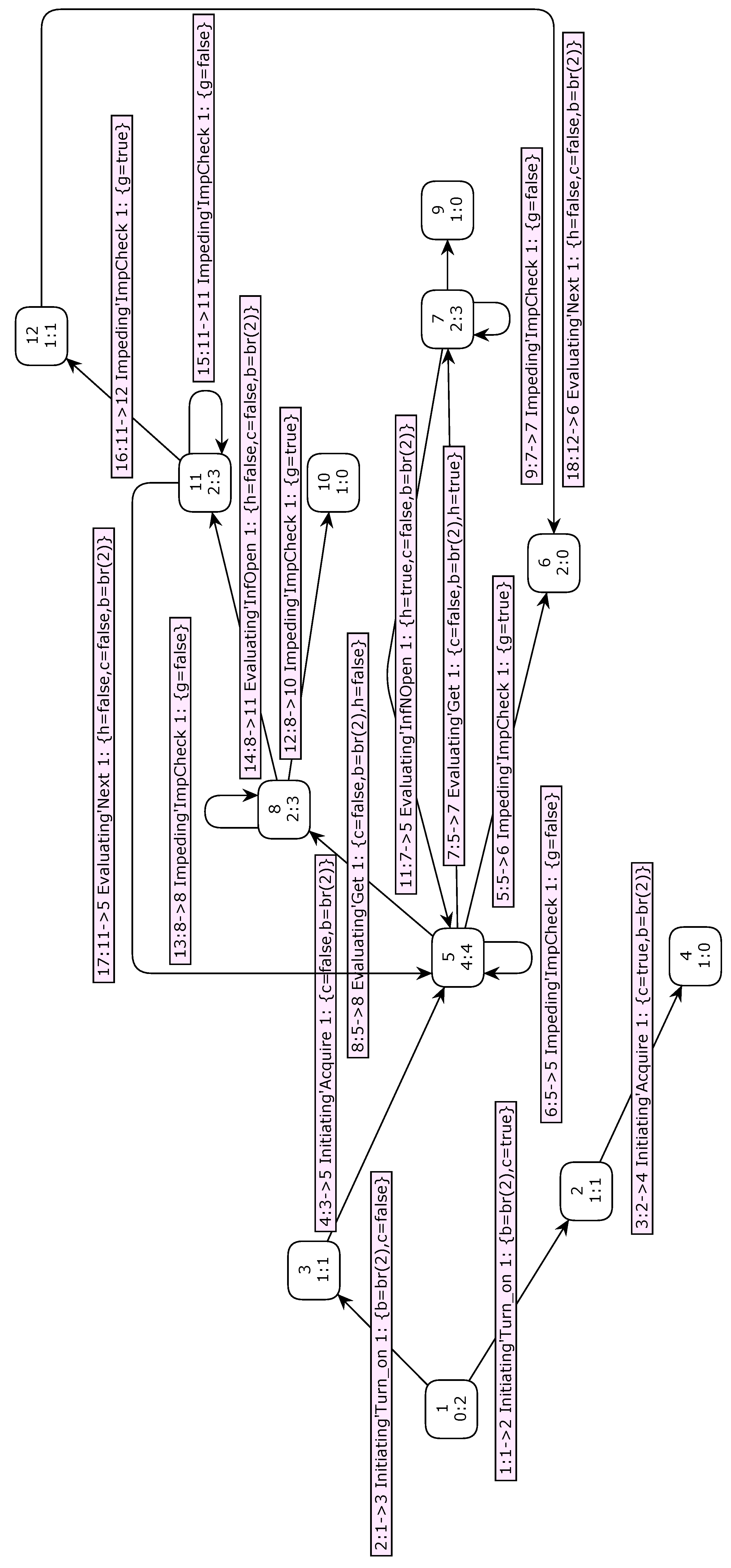
In order to facilitate model checking comprehension, full state space for the alarm manager component is presented in Figure 21. The page names of the initiating, evaluating and impeding modeling are Initiating, Evaluating and Impeding respectively. Each node represents a reachable marking, whereas each arc represents the occurrence of a binding element, taking system marking from source node to destination node. In each node, there is a number in internal and superior side, indicating the respective number associated to this marking. By definition, initial marking is 1. In each node, there are also two numbers separated by ”:” in internal and inferior side: the left number indicates quantity of antecessor nodes and the right number indicates quantity of successor nodes.
In this full state space, marking 3 is reached from marking 1 when transition Turn on fires with binding elements b = br(2) and c = false, indicating no fault occurred with PV IED state associated to breaker 2 opening supervision. Then, marking 5 is reached from marking 3 when transition Acquire fires with binding elements b = br(2) and c = false, indicating 1 breaker opening supervision must be started. Moreover, marking 8 is reached from marking 5 when transition Get fires with binding elements b = br(2), c = false and h = false, indicating breaker 2 status is opened. Then, marking 11 is reached from marking 8 when transition Acquire fires with binding elements b = br(2), c = false and h = false, indicating a breaker 2 opening alarm needs to be generated.
In Appendix 7, the full state space analysis report of the 1 breaker opening supervision model is presented. With this report, analysis of dynamic properties, already presented in SubSection 3.1.2, can be carried out, which are very efficient forms of formal analysis of the proposed model in this work.
In this report, note that some of the wished characteristics to be modeled can be checked, based on the analysis of dynamic properties of the proposed model. For example, two desirable characteristics to model are that there are no live and dead transitions, because these characteristics would indicate erroneous behaviors of the proposed model. Analysis of dynamic properties contributes to proving the functional correctness and then reliability of the proposed approach. Similar checkings to the ones that were previously carried out for dead and live transitions can be carried out through of the analysis of the dynamic properties of the proposed model shown.
In order to check a specific behavior of the alarm manager proposed approach, query codes in ASK-CTL are described with their respective answers and short explanations related to these codes as follow:
-
Query 1:Reachable (11,5)Answer 1:val it = true: boolQuery 1 and its respective answer mean marking 5 can be reached out from marking 11.
Marking 5 is correctly reached out from marking 11 as when transition Next fires with binding elements b = br(2), c = false and h = false, indicating a breaker 2 opening alarm generation, according to the previous descriptions.
-
Query 2:AllReachable ()Answer 2:val it = false: boolQuery 2 and its respective answer mean not all markings are reachable one from the other.
Answer 2 is correct as, for instance, marking 2 can not be reached out from marking 3, according to the previous descriptions.
These queries through CPN ML functional programming language contribute to the proof of the functional correctness and then reliability of the alarm manager proposed approach. Similar analytics through CPN ML language can be accomplished about some other behaviors of the alarm manager proposed approach if a better comprehension of the modeling dynamic proprieties is needed.
After analysing the results of this work, some discussions are highlighted in Section 5.
5. Discussions
At present, conventional methods for reliability modeling in energy systems involve a subjective component due to being predominantly executed manually by reliability engineers. The proficiency and expertise of these engineers significantly influence the system’s functional correctness. Additionally, the hardware topology impacts the system’s reliability rate and complicates the adaptability of the system. With the increasing integration and complexity of contemporary energy systems, reliability engineers face growing difficulties in comprehending system behaviors, leading to a higher likelihood of errors in results acquisition and a consequent reduction in the accuracy of reliability assessments.
In this scenario, there is a clear gap in the literature between operator’s skills and hardware topology in terms of reliability, which demands an academic contribution. In this sense, the proposed malleable model design approach in this work provides a formulation and solution to the integration error problem in critical systems supervision with bidirectional connection between static and dynamics behaviors. This tendency to build flexible models for power system automation has been widely sought after in the last decade [17,19,25,26].
Considering the Eletrobras Chesf PV-WF-BESS HPP as real-unit test case makes the proposed methodology achievable to practical applications. If appropriate adjustments are made, then malleable model can be used for other kinds of energy generation source, such as energy generation from a hydroelectric power plant. Furthermore, as the developed malleable model was built according to a methodology, the structured and scalable generalization with this method can be accomplished not only to other contexts in power system beyond supervisory one, but also with other contexts beyond power system, such as aircraft systems and aerospace sector.
Although PN has not still been used in the context of HPP automation system software architecture, modeling of critical systems through PN is promising because the behavior of these systems can be represented in a very detailed way and through formal methods. Therefore, the use of algorithms and proprieties of this formalism to formal analysis of these systems is possible. Developed mathematical representations are powerful checking and validation tools since they are strict. HCPN guarantees functional correctness by construction and some required proprieties are reached from this formal approach. In this way, malleable model design approach contributes to reliability in the supervision of critical systems and begins current trend in the academy [15,16].
On the other hand, along with the numerous advantages, a significant drawback of CPN analysis can be identified, namely, the issue of state space explosion [7,24], which leads to a notable increase in the computational complexity of the analysis. In order to mitigate this challenge, it is imperative to:
- Construct and examine occurrence graphs through the utilization of computational tools and also use techniques to reduce occurrence graphs while preserving a significant amount of information;
- Employing a hierarchical approach for enhancing system management efficiency and avoid unnecessary states.
Using these techniques to reduce occurrence graphs, a reduced graph can be obtained that contains exactly the same information as the complete occurrence graph. These reduced graphs can be used to investigate all systemic properties that can be investigated through complete occurrence graphs. These reduced graph investigations are much more efficient. In this work, it is used multi-set bounds to reduce the state space graph by bounding the number of tokens in certain places. By restricting the potential sizes of multi-sets in specific places, the combinatorial explosion of states can be reduced in CPN model. This is especially beneficial in scenarios where there exist places with large or unbounded token populations which may result in a considerable state space. More information about these occurrence graph reduction methods can be obtained in [10,11].
Applying hierarchical modelling in CPN may also contribute to the effective management and reduction of the state space in a complex system through the segmentation into smaller and more manageable sub-models. The hierarchical organization plays a pivotal role in controlling state space explosion, thereby facilitating the analysis and checking of the system.
6. Conclusions
The malleable model approach in this work provides an important contribution to the reliability of the critical systems based on software architecture. The presented solution has the advantages of not having dependence on expert knowledge and hardware topology, with the possibility of easy adaptation due to being structured and systematized in informal and formal approaches. In this way, the malleable model can facilitate the maintenance and/or analysis extension of the critical systems, since the development of these systems supervision involves maintaining operation and fault tolerance.
The proposed framework to formulate and solve the integration error problem of the critical systems provides evidence that the method is applicable in power plant supervision. A HPP real- unit test case was considered with all of the automation layers in order to exemplify this framework. As the approach was developed in this work, particularly, for a HPP, it can be used by electrical companies what can represent relevant operational and financial advantages in the long term due to the frequently occurence of large-scale emergency situations and the high cost of errors in business plans.
For informal approach, C4 diagram was used to obtain the software documentation, while a logical modeling with HCPN was used to describe the formal approach. Using HCPN, it is possible to represent in a concise, detailed, direct, structured and practical way the dynamic behavior of the HPP supervision system. Analysis with validation - simulation and MSC - and checking - full state space and ASK-CTL temporal logic - in HCPN was important because this proved and valued the functional correctness of the proposed framework in energy domain. This analysis can also detect some problems in malleable modeling design.
As future work, the generic methodology presented can be developed using other informal and formal approaches, as well as for systems other than HPP supervision, bringing all the benefits of the methodology to the context in which it will be applied. Furthermore, the development of the malleable model will also be carried out in the safety aspects of the critical system, providing robustness to the reliability analysis.
Funding
This research received no external funding.
Data Availability Statement
The presented data in this work are available on request from the corresponding author. The data are not publicly available due to the company’s strategic considerations.
Acknowledgments
The authors would like to thank Eletrobras CHESF for sharing data; technical and financial support to the research; and SENAI CIMATEC for the technical-scientific and financial support to the project from Public Call for R&DI No. 02/2017 and with code PD-00048-0217 in the ANEEL base.
Conflicts of Interest
The authors declare no conflict of interest.
7. Full State Space Analysis Report
7.1. 1 Breaker Opening Supervision Model
CPN Tools state space report for:
/cygdrive/C/Users/LucianoAntonioCalmonLisboa/Paper/
1_Breaker_Opening_Supervision_Rev2_3.cpn
Report generated: Sat May 11 21:20:17 2024
Statistics
_________________________________________________
State Space
Nodes: 12
Arcs: 18
Secs: 0
Status: Full
Scc Graph
Nodes: 9
Arcs: 9
Secs: 0
Boundedness Properties
_________________________________________________
Best Integer Bounds
Upper Lower
Evaluating’Evaluation 1 1 0
Evaluating’NoBlock 1 1 0
Evaluating’Opened 1 1 0
Evaluating’Ready 1 1 0
Impeding’Block 1 1 0
Impeding’Checking 1 1 0
Impeding’NoBlock 1 1 0
Initiating’Analysis 1 1 0
Initiating’Block 1 1 0
Initiating’Checking 1 1 0
Initiating’NoBlock 1 1 0
Initiating’Ready 1 1 0
Initiating’Start 1 1 0
Best Upper Multi-set Bounds
Evaluating’Evaluation 1 1‘(br(2),false,false)++ 1‘(br(2),false,true)
Evaluating’NoBlock 1 1‘a
Evaluating’Opened 1 1‘(br(2),false,false)
Evaluating’Ready 1 1‘(br(2),false)
Impeding’Block 1 1‘a
Impeding’Checking 1 1‘a
Impeding’NoBlock 1 1‘a
Initiating’Analysis 1 1‘(br(2),false)++ 1‘(br(2),true)
Initiating’Block 1 1‘a
Initiating’Checking 1 1‘a
Initiating’NoBlock 1 1‘a
Initiating’Ready 1 1‘(br(2),false)
Initiating’Start 1 1‘a
Best Lower Multi-set Bounds
Evaluating’Evaluation 1 empty
Evaluating’NoBlock 1 empty
Evaluating’Opened 1 empty
Evaluating’Ready 1 empty
Impeding’Block 1 empty
Impeding’Checking 1 empty
Impeding’NoBlock 1 empty
Initiating’Analysis 1 empty
Initiating’Block 1 empty
Initiating’Checking 1 empty
Initiating’NoBlock 1 empty
Initiating’Ready 1 empty
Initiating’Start 1 empty
Home Properties
_________________________________________________
Home Markings
None
Liveness Properties
_________________________________________________
Dead Markings
[4,6,9,10]
Dead Transition Instances
None
Live Transition Instances
None
Fairness Properties
_________________________________________________
Impartial Transition Instances
None
Fair Transition Instances
Initiating’Acquire 1
Initiating’Turn_on 1
Just Transition Instances
None
Transition Instances with No Fairness
Evaluating’Get 1
Evaluating’InfNOpen 1
Evaluating’InfOpen 1
Evaluating’Next 1
Impeding’ImpCheck 1
| 1 | Reliability is an attribute of a system performs its intended function appropriately for a specified period of time or in a defined environment without failure. |
| 2 | Functional correctness is the characteristic of a system to attend to its specification. |
| 3 | Informal methods are more qualitative than quantitative and frequently base their conclusions on the recommendation of experts. |
| 4 | Formal methods are mathematically strict techniques for specifying, developing, analyzing, checking and validating software and hardware systems. |
| 5 | Software architecture can be defined as the high-level structures of a software system, which include the software elements, their relationships and properties, as well as the practices used to select, define, or design these structures. |
| 6 | Multi-set is a variant on the idea of a set in which each of its elements can have more than one occurrence, in contrast to a set. |
| 7 | Input pattern lists the variables that can be used in the code action. |
| 8 | Output pattern lists the variables to be changed as a result of the execution of the code action. |
| 9 | Code action is executed as a local declaration in an environment containing the variables specified in the input pattern. When the code action has been executed, its result is applied to bind the variables in the output pattern. |
| 10 | A CPN’s variable components are named tokens. They reflect the value of a condition and are shown inside of a place. |
| 11 | If a colour set is built up from other colour sets, it is named compound (product colour set, record colour set, list colour set, union colour set, subset colour set and alias colour set); if not, it is named simple (unit colour set, boolean colour set, integer colour set, large integer colour set, real colour set, time colour set, string colour set, enumerated colour set and index colour set). |
| 12 | In a CPN, tokens have a data value associated with them. The data value associated with a token is known as the token colour. |
| 13 | Expr is the set of expressions provided by the CPN ML inscription language which specifies declarations and net inscriptions. This language is an extension of the functional programming language Standard ML. |
| 14 | Type(e) is the type of an expression e∈ Expr, i.e., the type of Var(e) (the values obtained when evaluating e). |
| 15 | The subscript MS denotes the multi-set of the associated place. |
| 16 | The liveness property of a PN refers to the ability of the system to ensure that all transitions can eventually occur, preventing deadlock or livelock situations. |
| 17 | The boundedness property of a PN refers to the condition where the net has limitations on the number of tokens that can be present in each place, ensuring a finite state space. |
| 18 | Fairness in PN is a crucial property ensuring actions in the system model are starvation-free, that is, no component is delayed indefinitely in a composed model, promoting effective reuse and composability checking through PN transformations and analysis techniques. |
| 19 | Validation is the essential procedure of confirming that a software system or component satisfies the specified criteria and operates effectively within its designated environment. The primary goal of this validation stage is to identify and correct any errors in the software to guarantee its compliance with the user requirements and its proper functioning. |
| 20 | Checking refers to the procedure of verifying software artifacts against desired properties using formal checking techniques. The employment of strict methodologies, including formal methods, is underscored in the field of software engineering with the aim of preserving the initial engineered elements of a product and averting designs from straying away from their designated objectives, underscoring the significance of comprehensive verification processes in software development. |
| 21 | More information about CPN Tools can be obtained in https://cpntools.org/. |
| 22 | This work was idealized in the Research, Development and Innovation (R&D+I) Project with code number PD-00048-0217, being regulated by the National Electric Energy Agency (ANEEL). |
| 23 | OPC UA is a cross-platform, open-source, IEC62541 standard for data exchange from sensors to cloud applications developed by OPC Foundation. |
| 24 | In boolean logic, a don’t-care term (X) for a function is an input-bit for which the function output does not matter. |
| 25 | Counterexample is an example that presents an argument in opposition or contradiction to a particular concept or hypothesis. |
References
- Y. An, N. Wu, X. Zhao, X. Li and P. Chein. Hierarchical Colored Petri Nets for modeling and Analysis of Transit Signal Priority Control Systems. Applied Sciences, 8, 141, 2018, pp. 1–24.
- N. T. S. Board. Pipeline Accident Report. N. T. S. Board, Washington, DC, USA. NTSB/PAR-12/01 PB2012-916501. 2010.
- S. Brown. The C4 Diagram for Software Architecture. 2018. Available online: http://c4model.com/.
- S. Brown. Documentation C4 Diagram to Software Architecture. (in Portuguese). Available online: https://www.infoq.com/br/articles/C4-architecture-model/.
- T. Cherifi and L. Hamami. A Practical Implementation of Unconditional Security for the IEC 60780-5-101 SCADA Protocol. International Journal of Critical Infrastructure Protection, Vol. 20, 2018, pp. 68–84.
- S. Christensen and K. Mortensen. Design/CPN ASK-CTL Manual Version 0.9, University of Aarhus, Department of Computer Science, University of Aarhus, Denmark, 1996.
- E. Clarke, O. Grumberg, S. Jha, Y. Lu, and H. Veith. Progress on the State Explosion Problem in Model Checking. Informatics: 10 Years Back, 10 Years Ahead, 2001, pp. 176–194.
- Federal Energy Regulatory Comission (FERC), North American Electric Reliability Corporation (NERC) and Regional Entities (Midwest Reliability Organization, Northeast Power Coordinating Council, Reliability First Corporation, SERC Corporation, Texas Reliability Entity and Western Electricity Coordinating Council). FERC, NERC and Regional Entity Staff Report. The February 2021 Cold Weather Outages in Texas and the South Central United States. 2021. Available online: https://www.ferc.gov/media/february-2021-cold-weather-outages-texas-and-south-central-united-states-ferc-nerc-and.
- J. Huang, T. Meng, Y. Deng and F. Huang. Catching Critical Transition in Engineered Systems. Mathematical Problems in Engineering 2021, 2021, 1–10.
- K. Jensen. Coloured Petri Nets: Basic Concepts, Analysis Methods and Practical Use, Vol. 1, 2nd Edition, New York, United States of America, 1997.
- K. Jensen. Coloured Petri Nets: Basic Concepts, Analysis Methods and Practical Use, Vol. 2, 2nd Edition, New York, United States of America, 1997.
- K. Jensen, S. Christensen and L. Kristensen. CPN Tools State Space Manual, University of Aarhus, Department of Computer Science, University of Aarhus, Denmark, 2006.
- R. Jongeling and F. Ciccozzi. Towards Supporting Malleable Architecture Models. 2023 IEEE 20th International Conference on Software Architecture Companion (ICSA-C), pp. 272-275, Italy, 2023.
- A. Van Lamsweerde. Requirements Engineering: From System Goals to UML Models to Software. Chichester, United Kingdom, John Wiley & Sons, 2009.
- X. Liang, Y. Hou, and M. Zhao. modeling and Analysis of Microgrid Energy Scheduling Based on Colored Petri Net. 2022 IEEE International Conference on Networking, Sensing and Control (ICNSC), pp. 1-6. 2022.
- X. Liu, M. Zhao, Z. Wei and M. Lu. The Energy Management and Economic Optimization Scheduling of Microgrid based on Colored Petri Net and Quantum-PSO Algorithm. Sustainable Energy Technologies and Assessments, Vol. 53, 102670, 2022.
- R. Lopez, A. Moore and J. Gillerman. A Model-Driven Approach to Smart Substation Automation and Integration for Comision Federal de Electricidad. IEEE PES T&D 2010, 2010, 1–8.
- P. M. Nasr. Toward modeling Alarm Handling in SCADA System: A Colored Petri Nets Approach. IEEE Transactions on Power Systems, Vol. 34, N. 6, 2019, pp. 4525-4532.
- P. Neis, A. A. Wehrmeister, M. F. Mendes and J. R. Pesente. Applying a Model-Driven Approach to the Development of Power Plant SCADA/EMS Software. International Journal of Electrical Power and Energy Systems, Vol. 153, 2023, 109336, pp. 1-15.
- F. Salehi, R. Keypour and W. Lee. Reliability Assessment of Automated Substation and Functional Integration. 2016 IEEE Industry Applications Society Annual Meeting, pp. 1-7. 2016.
- SCIENCE - Complex Systems and Networks. Science, 2009. Vol. 325, Issue 5939, 357-504. Available online: https://www.sciencemag.org/content/325/5939.toc.
- P. Stevens and R. Pooley. Using UML: Software Engineering with Objects and Components. Addison-Wesley, 2nd Edition, 2006.
- J. D. Ullman. Elements of ML Programming, ML 97 Edition, 2nd ed. Prentice Hall, 1998.
- A. Valmari. The State Explosion Problem. Proceedings of the Advanced Course on Petri Nets, 1996, pp. 429–528.
- C. W. Yang, V. Vyatkin and C. Pang. Service-Oriented Extension of IEC 61850 for Model-Driven Smart Grid Automation Design. 43rd Annual Conference of the IEEE Industrial Electronics Society (IECON), 2017, pp. 5489-5496.
- N. Zhou, D. Li, V. Vyatkin, V. Dubinin and C. Liu. Toward Dependable Model-Driven Design of Low-Level Industrial Automation Control Systems. IEEE Transactions on Automation Science and Engineering, Vol. 19, Issue 2, 2022, pp. 425-440.
- O. Zielinski, D. Nicklas, H. Colonius, M. Siegel, A. Hahn, J. Meike, F. Köster and K. Lemmer. Interdisciplinary Research Center on Critical Systems Engineering for Socio-Technical Systems. Progress Report. 2015.
Figure 1.
Spectra of the malleable model with artifacts. From: [13].
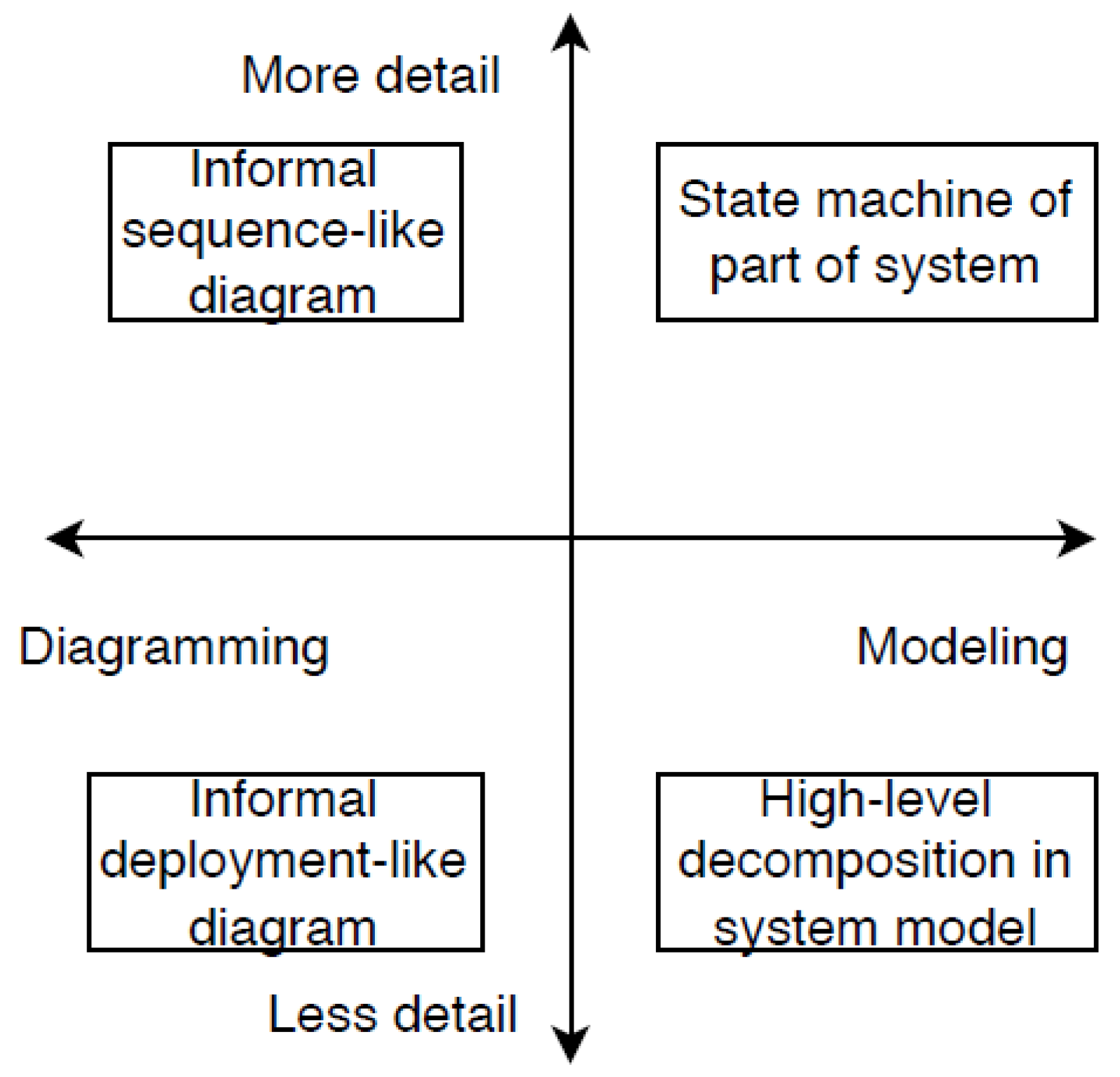
Figure 2.
Representation of the abstraction levels in a C4 diagram [3].
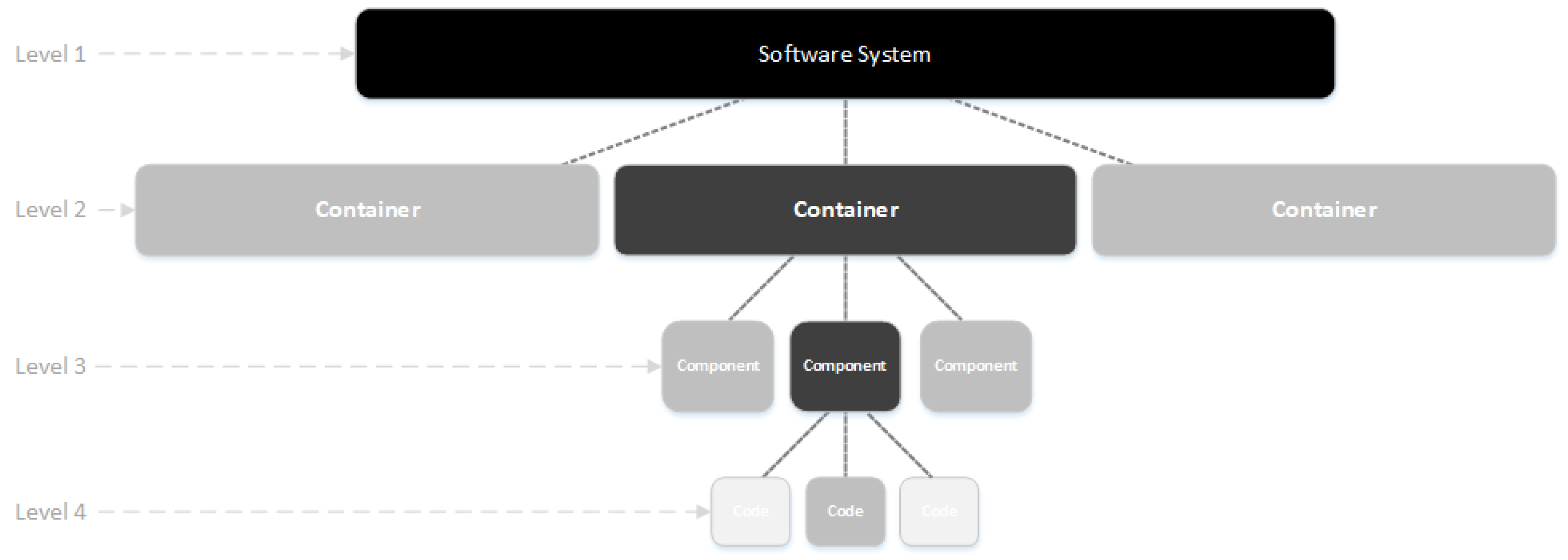
Figure 3.
Basic elements of a Coloured Petri Nets.
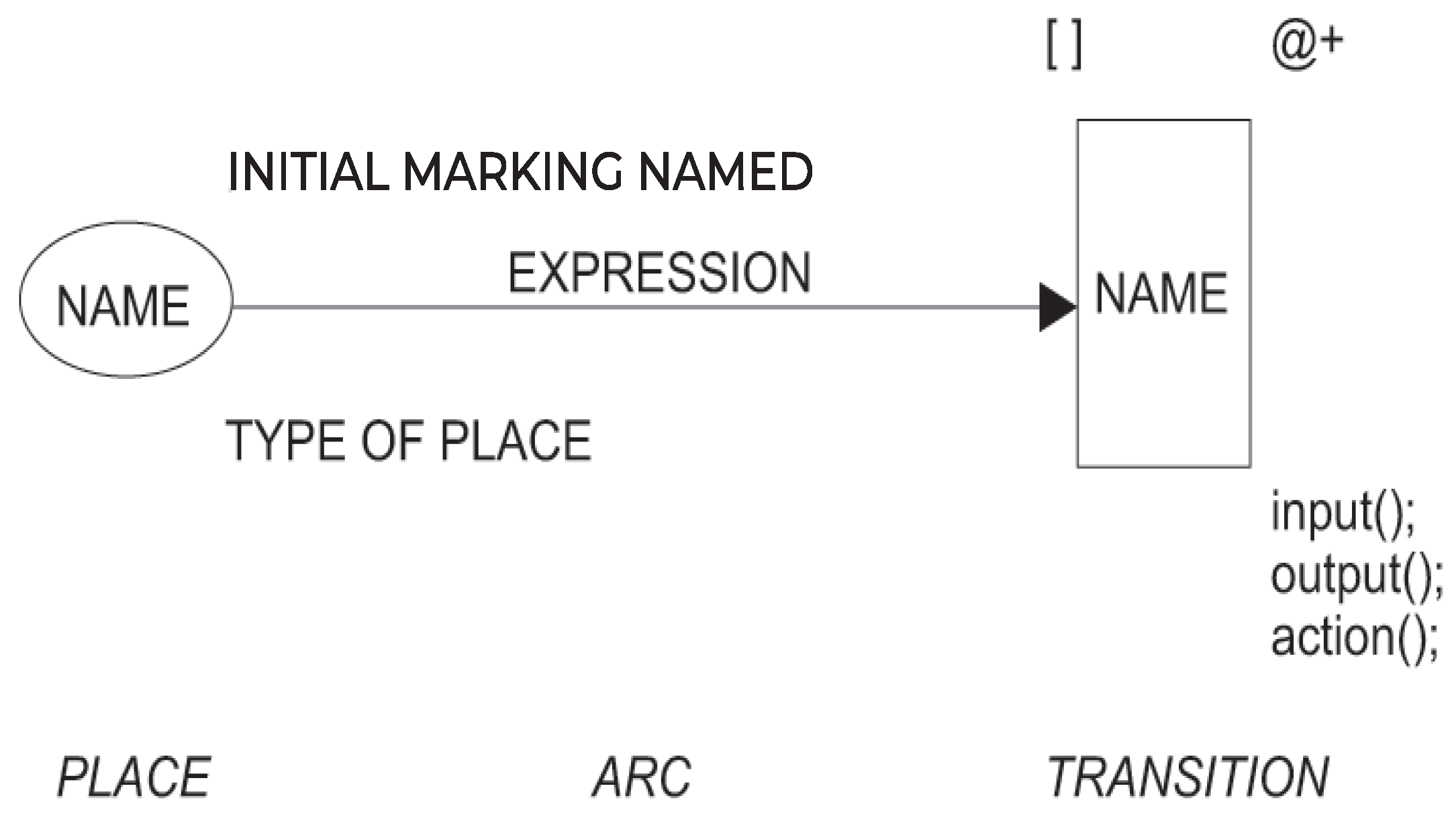
Figure 4.
The schematic diagram for the proposed methodology in the context of critical systems supervision.
Figure 4.
The schematic diagram for the proposed methodology in the context of critical systems supervision.
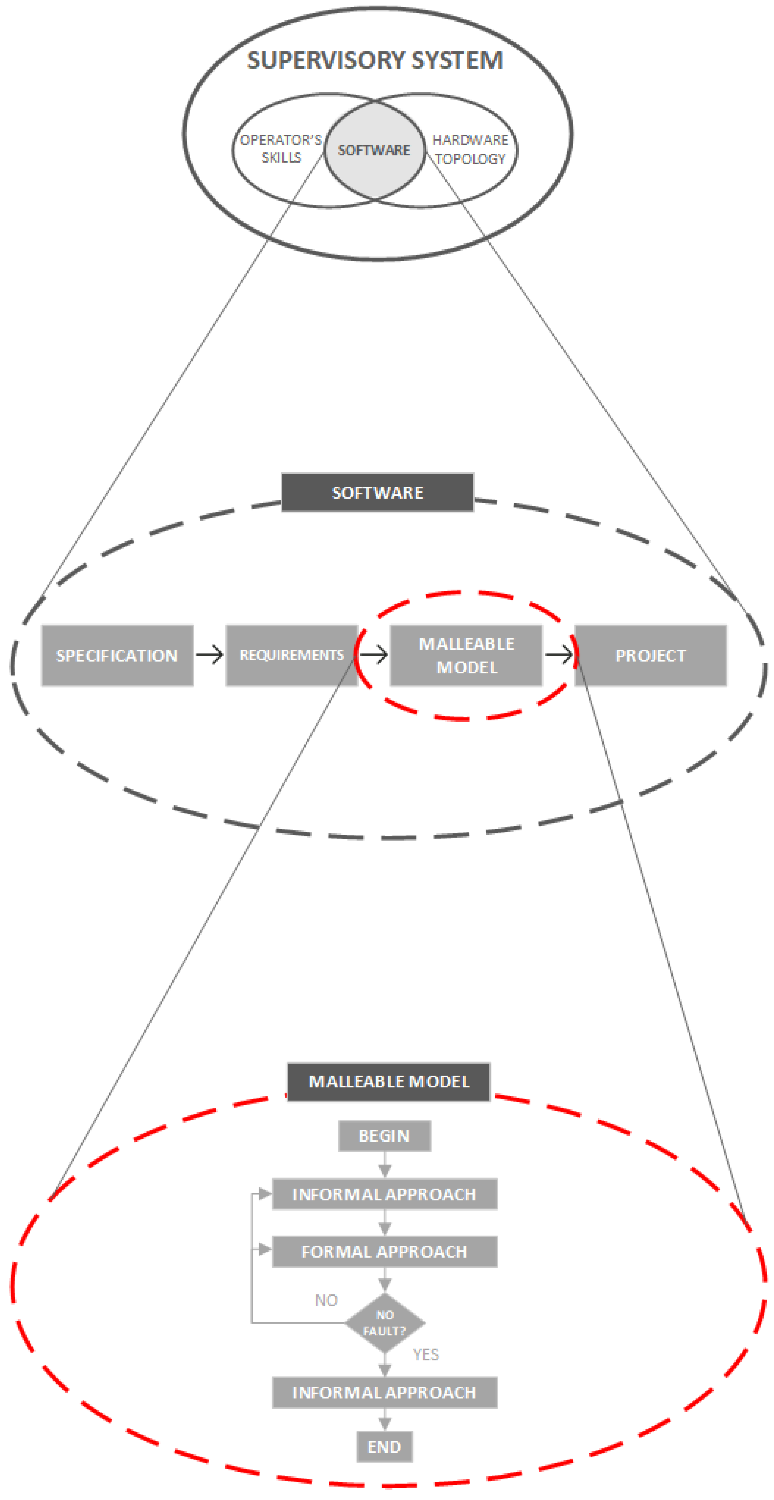
Figure 5.
Spectra of the proposed malleable model with artifacts adopted. Adapted from: [13].
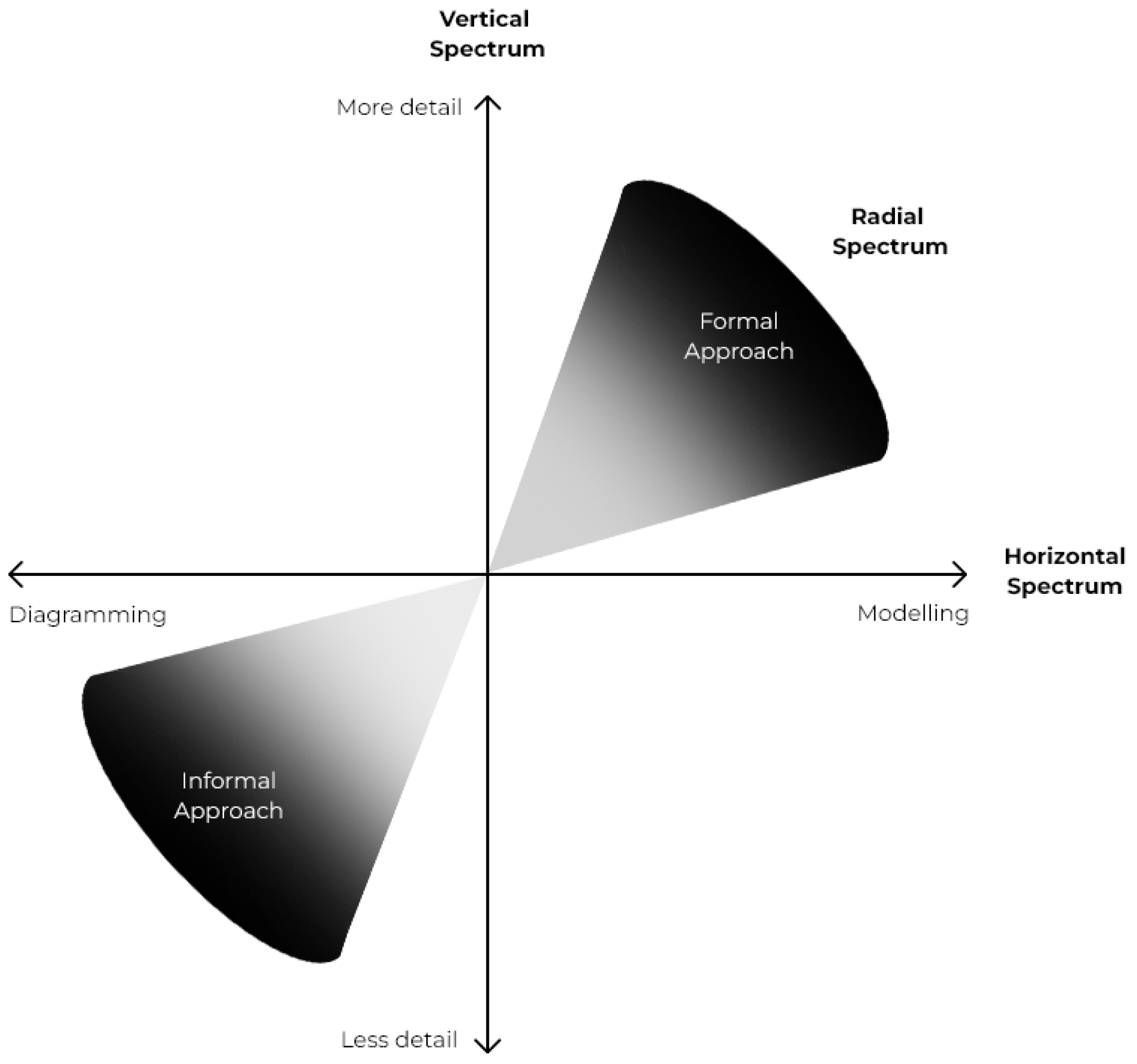
Figure 6.
Detailed proposed framework of building the malleable model using C4 diagram and HCPN.
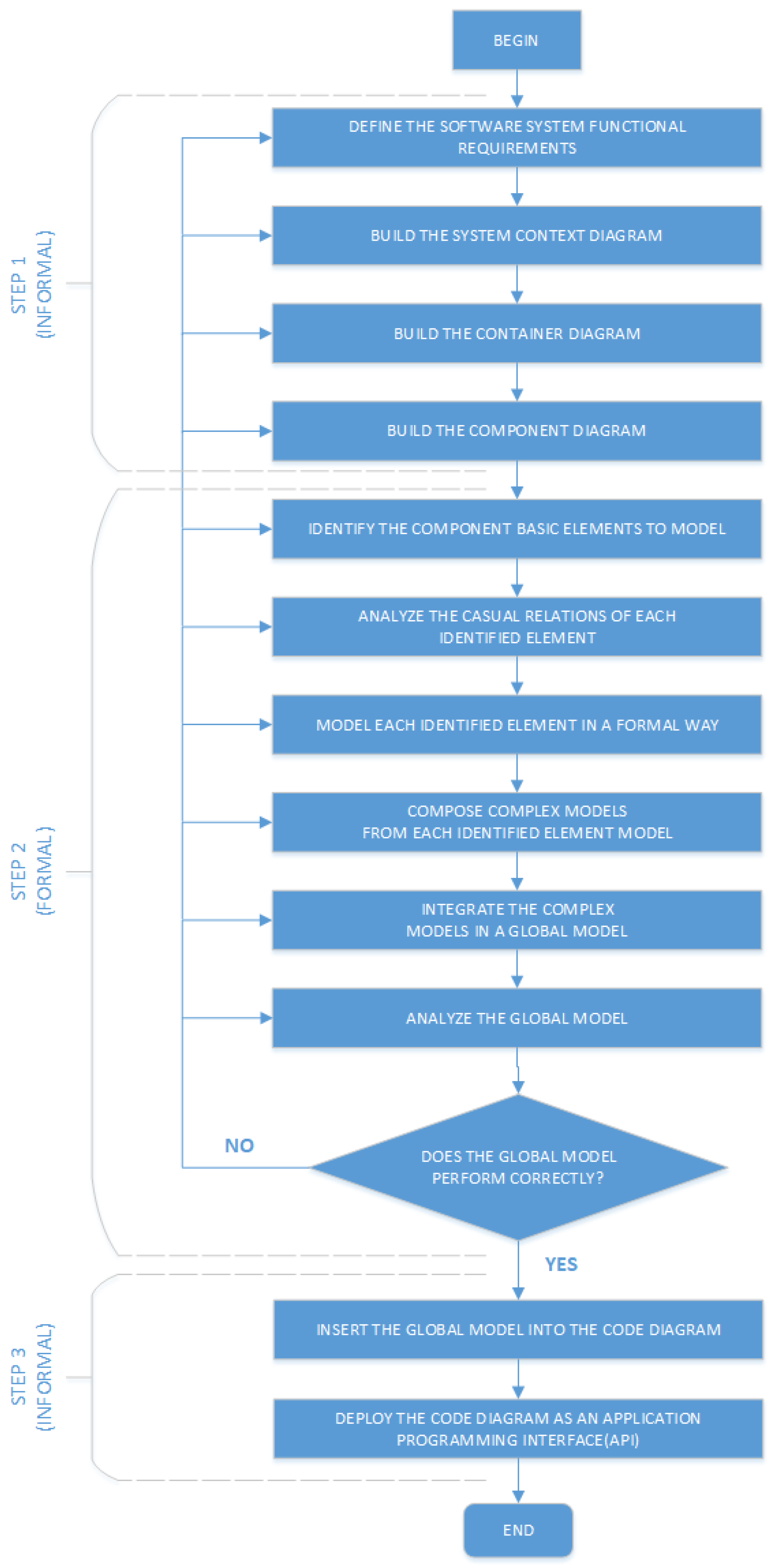
Figure 7.
A block diagram of the system entities interfaces.
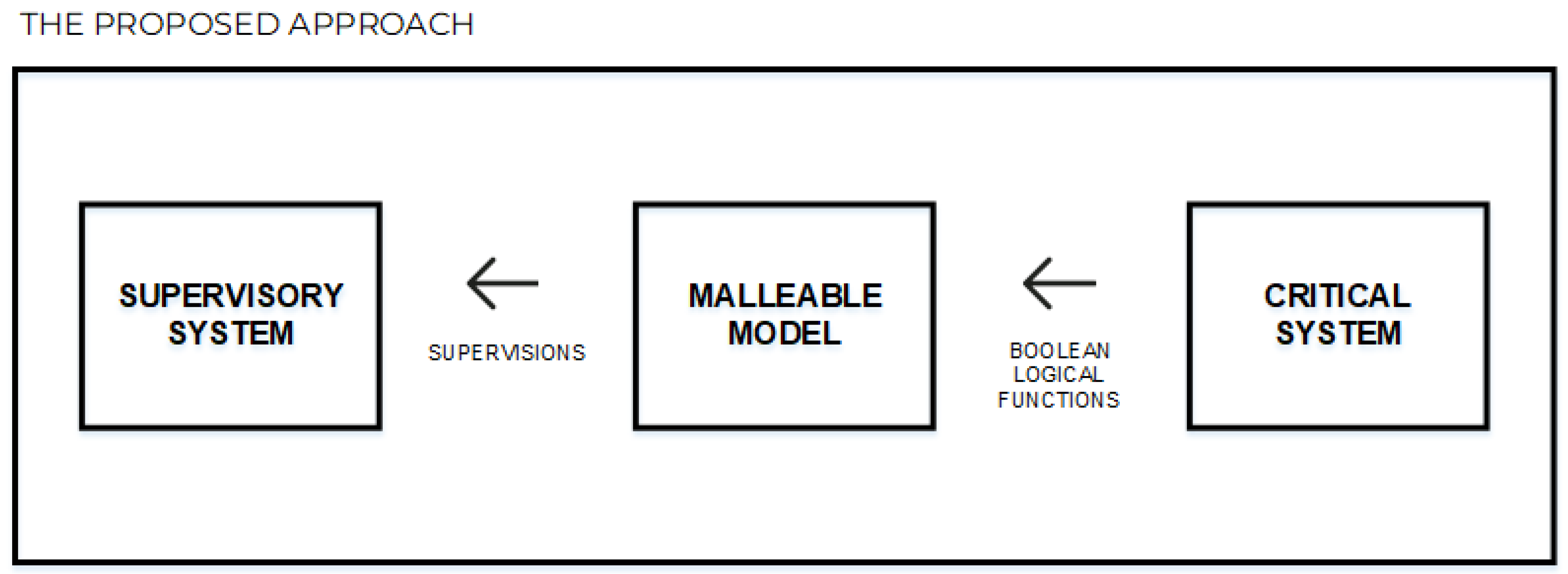
Figure 8.
Eletrobras Chesf PV-WF-BESS HPP general representation.
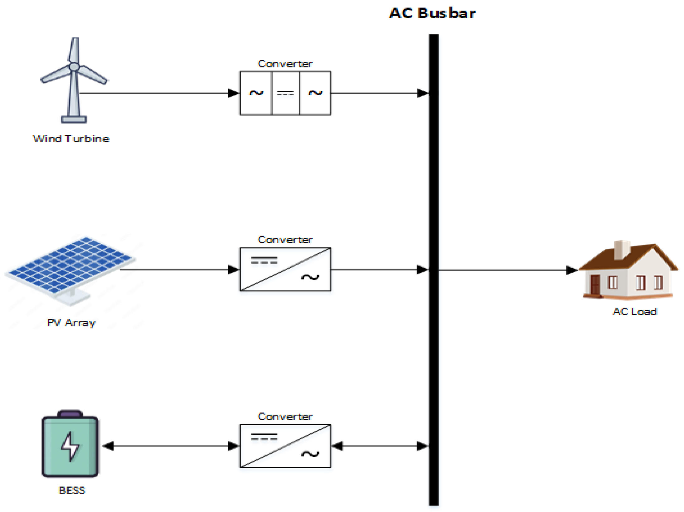
Figure 9.
Eletrobras Chesf PV-WF-BESS HPP automation architecture.
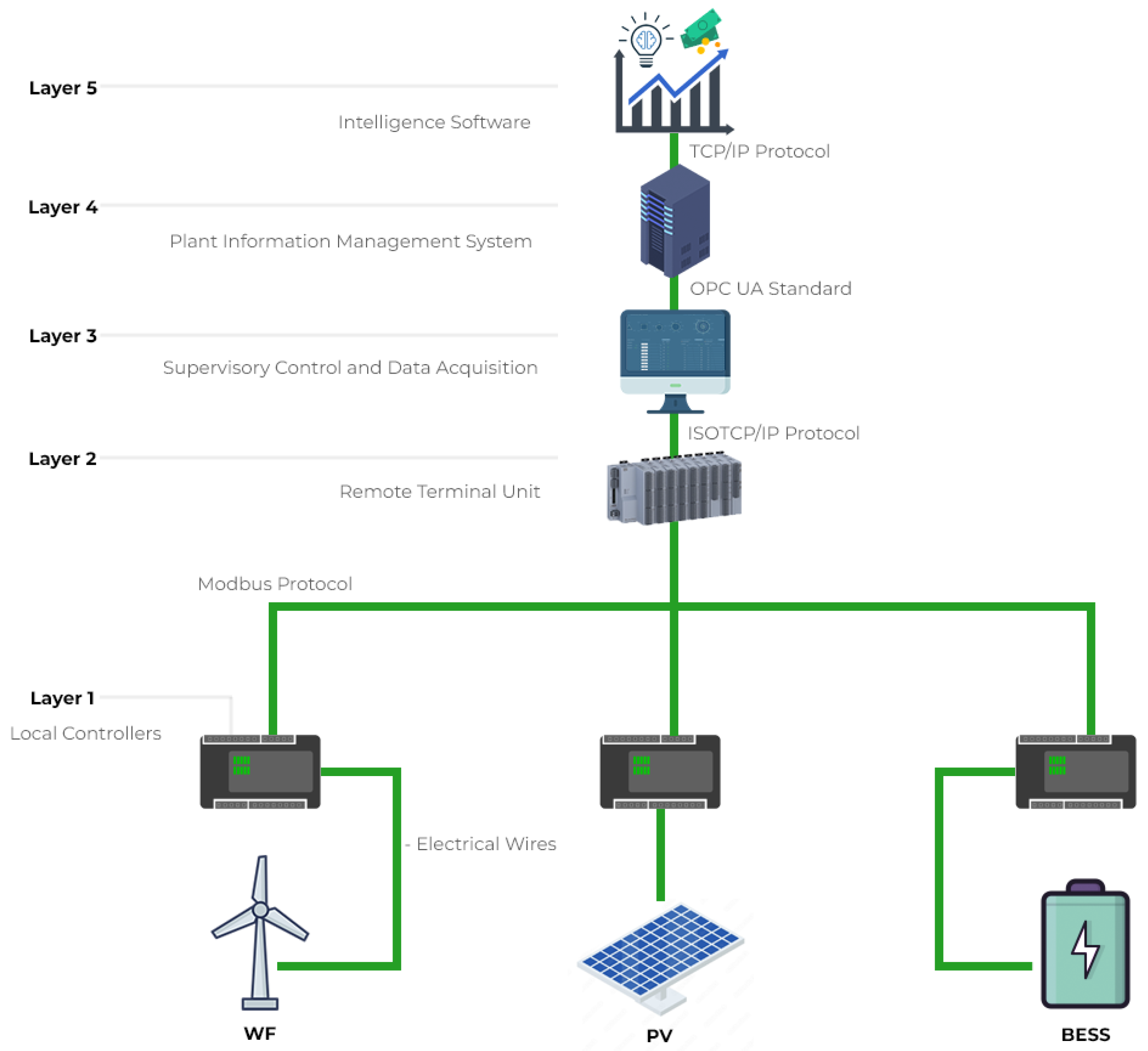
Figure 10.
Context C4 diagram for the Eletrobras Chesf PV-WF-BESS HPP supervision system.
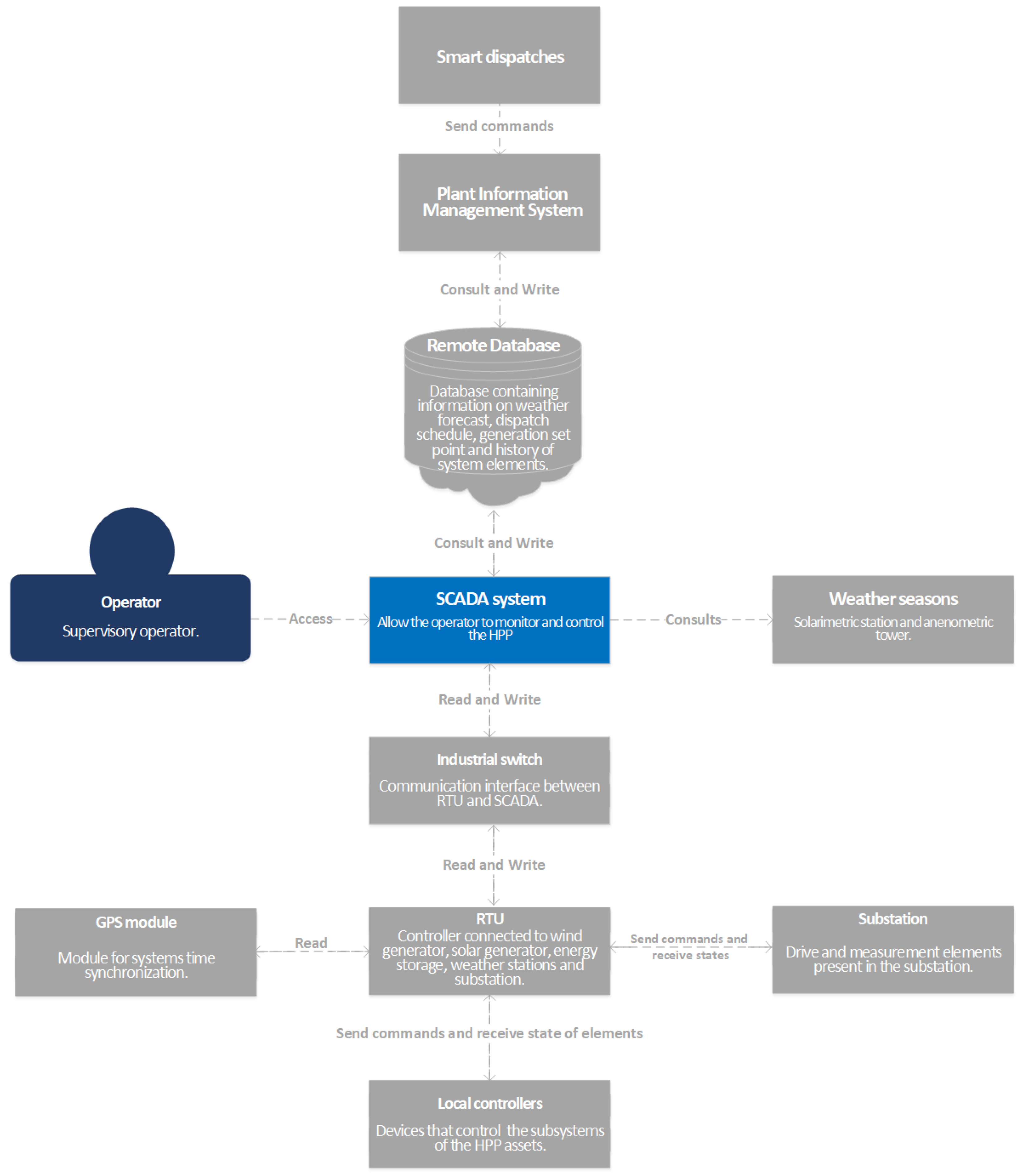
Figure 11.
Containers C4 diagram for the SCADA system.
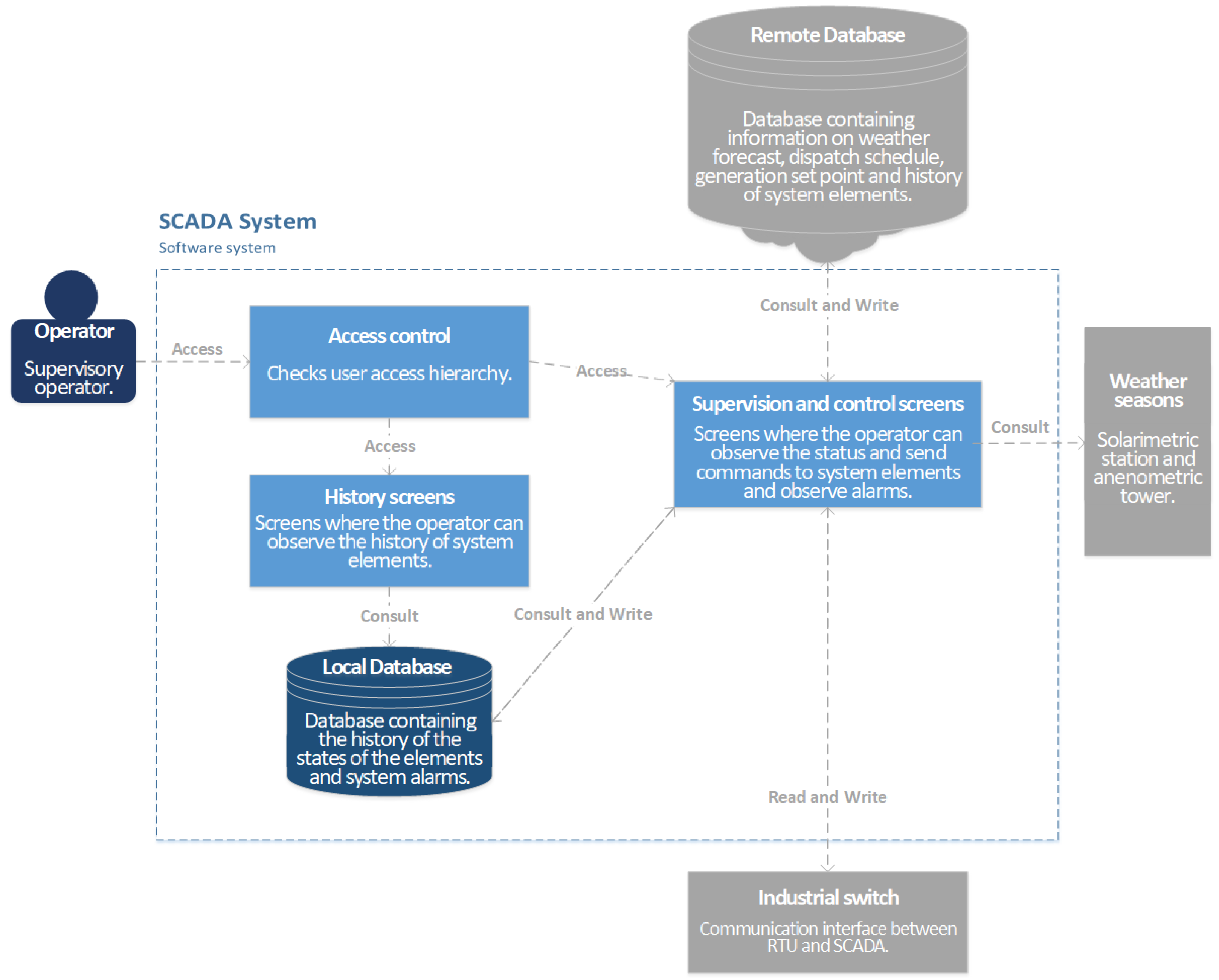
Figure 12.
Components C4 diagram for the Supervision and control screens.
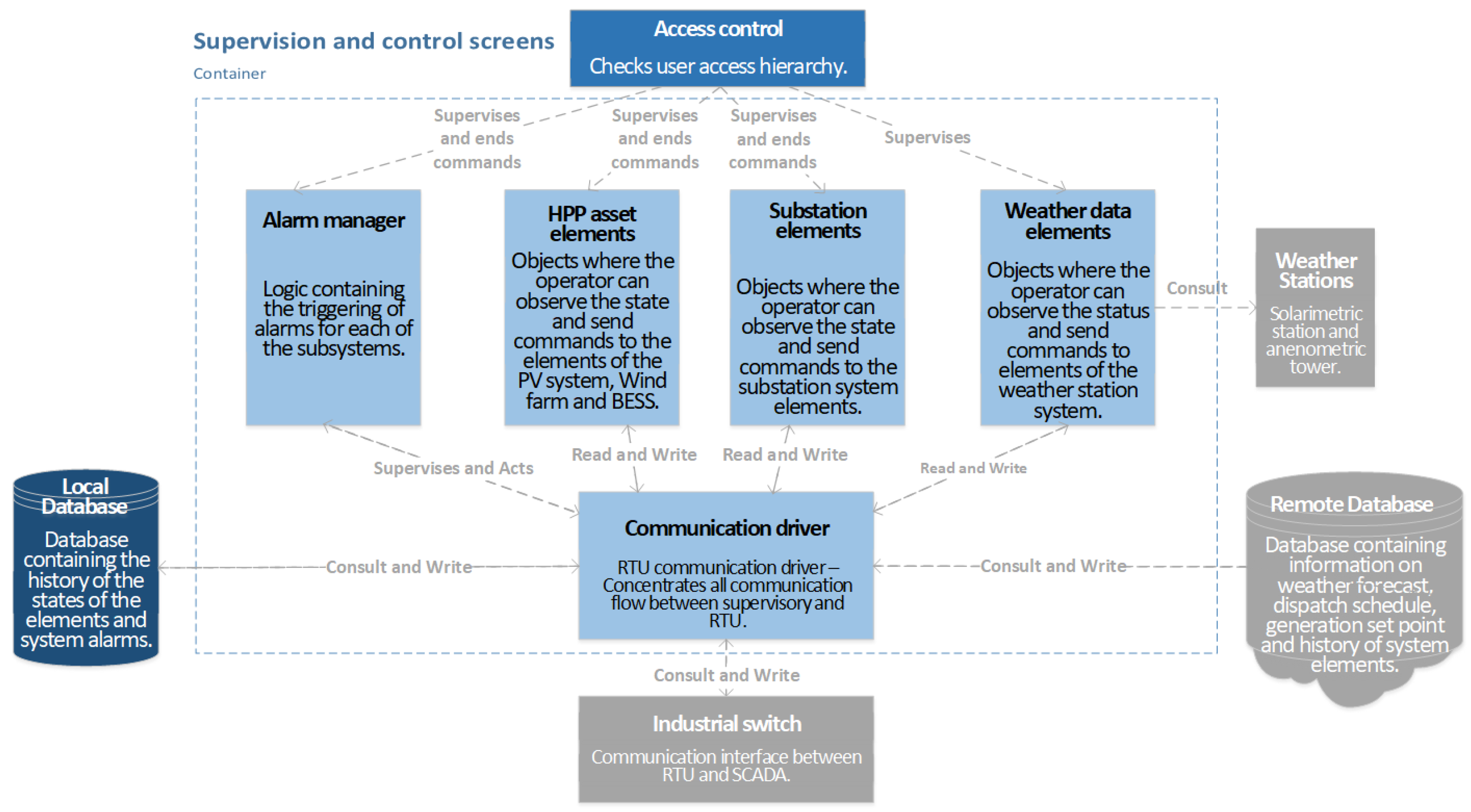
Figure 13.
Eletrobras Chesf PV-WF-BESS HPP general unifilar diagram.
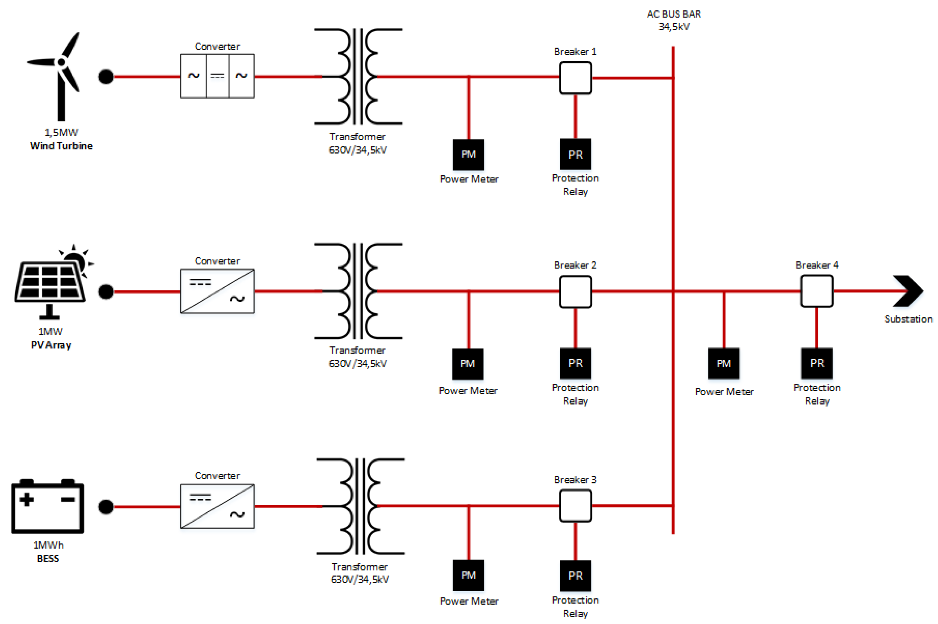
Figure 14.
A Block Diagram of the Pages Interfaces.
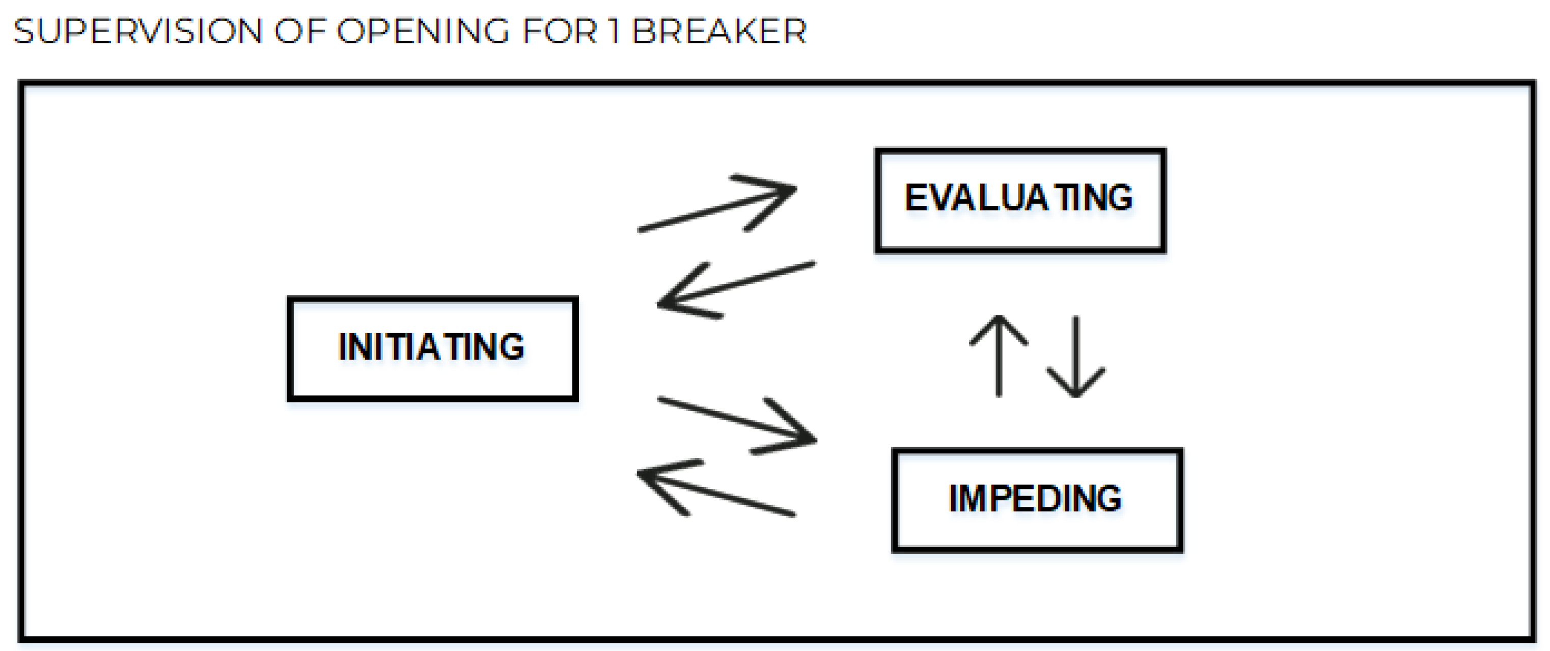
Figure 15.
Page Initiating for 1 breaker opening supervision in initial state.
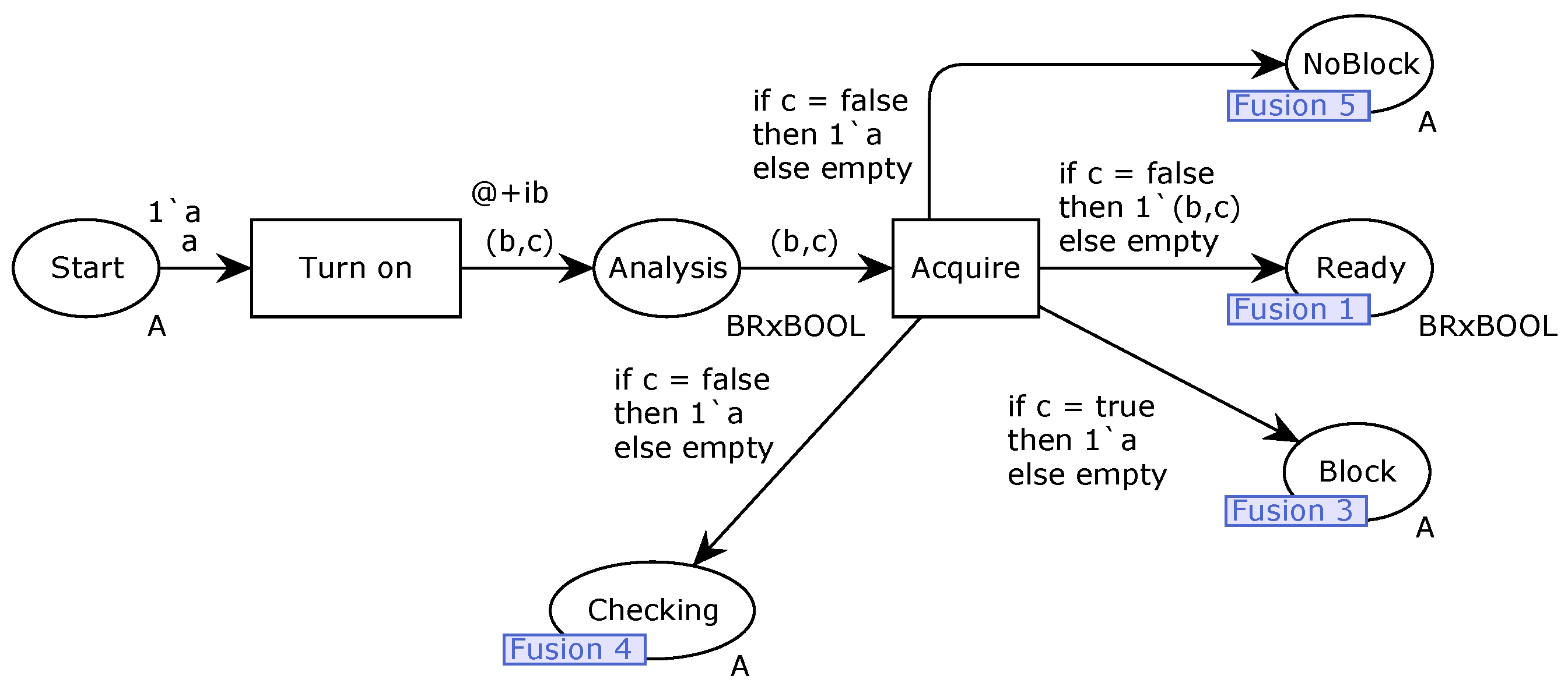
Figure 16.
Page Evaluating for 1 breaker opening supervision in initial state.
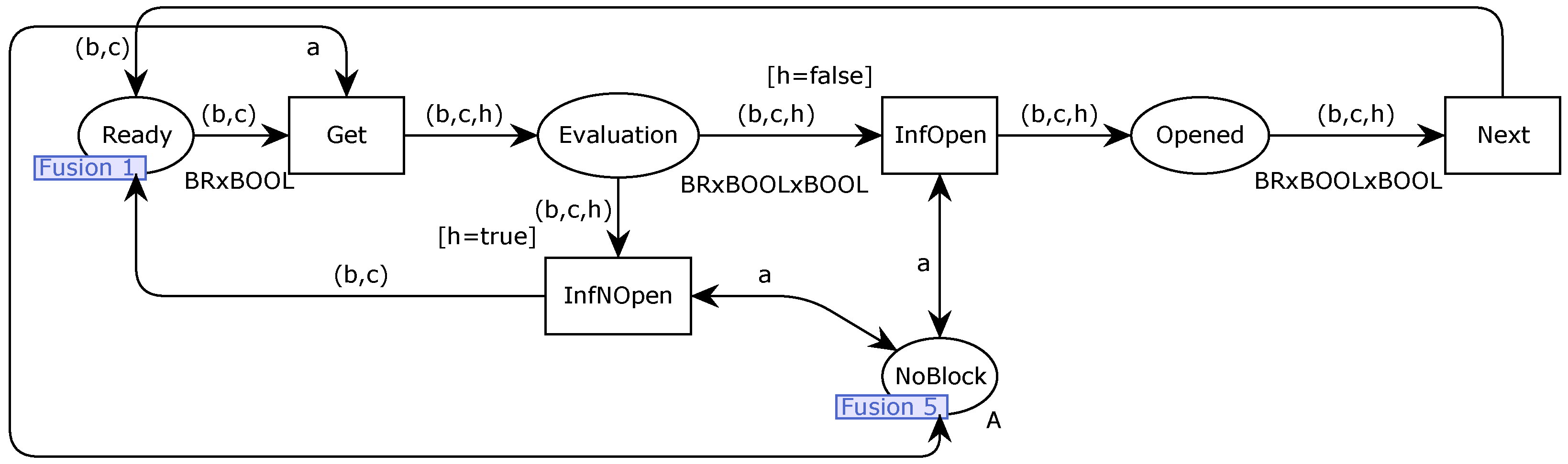
Figure 17.
Page Impeding for 1 breaker opening supervision in initial state.
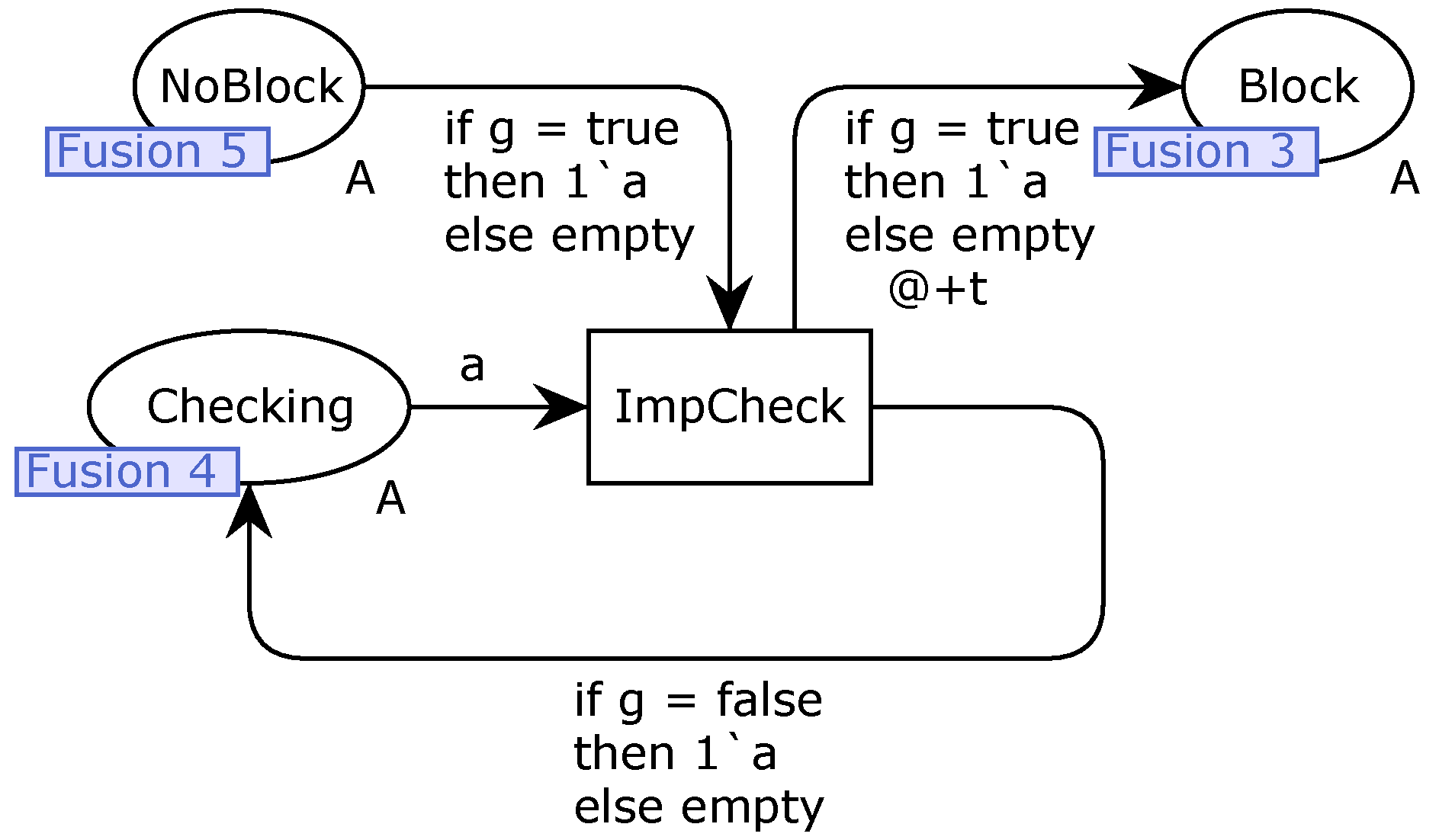
Figure 18.
Proposed Code Diagram Fluxogram for the 1 Breaker Opening Supervision.
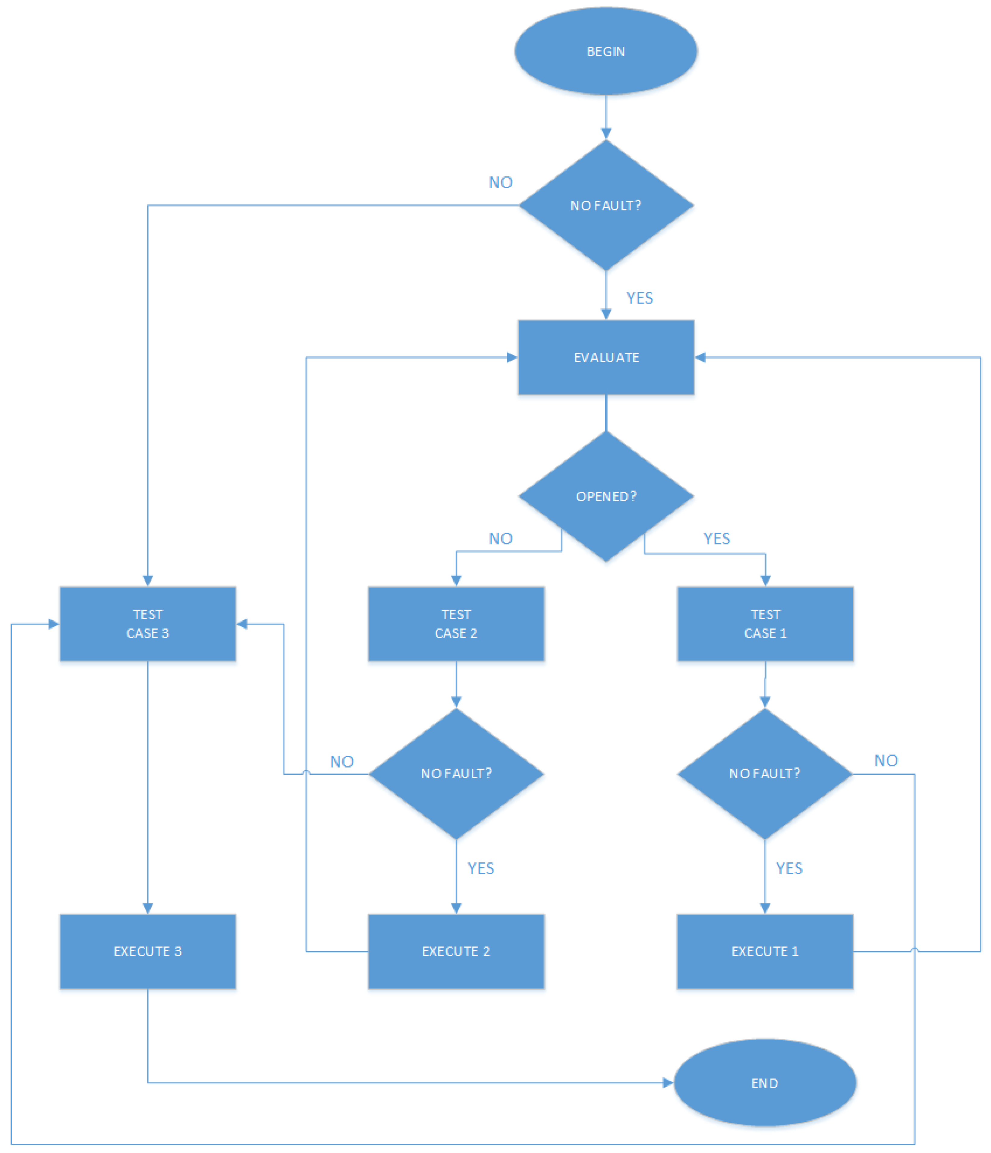
Figure 19.
Message Sequence Chart of Example 1.
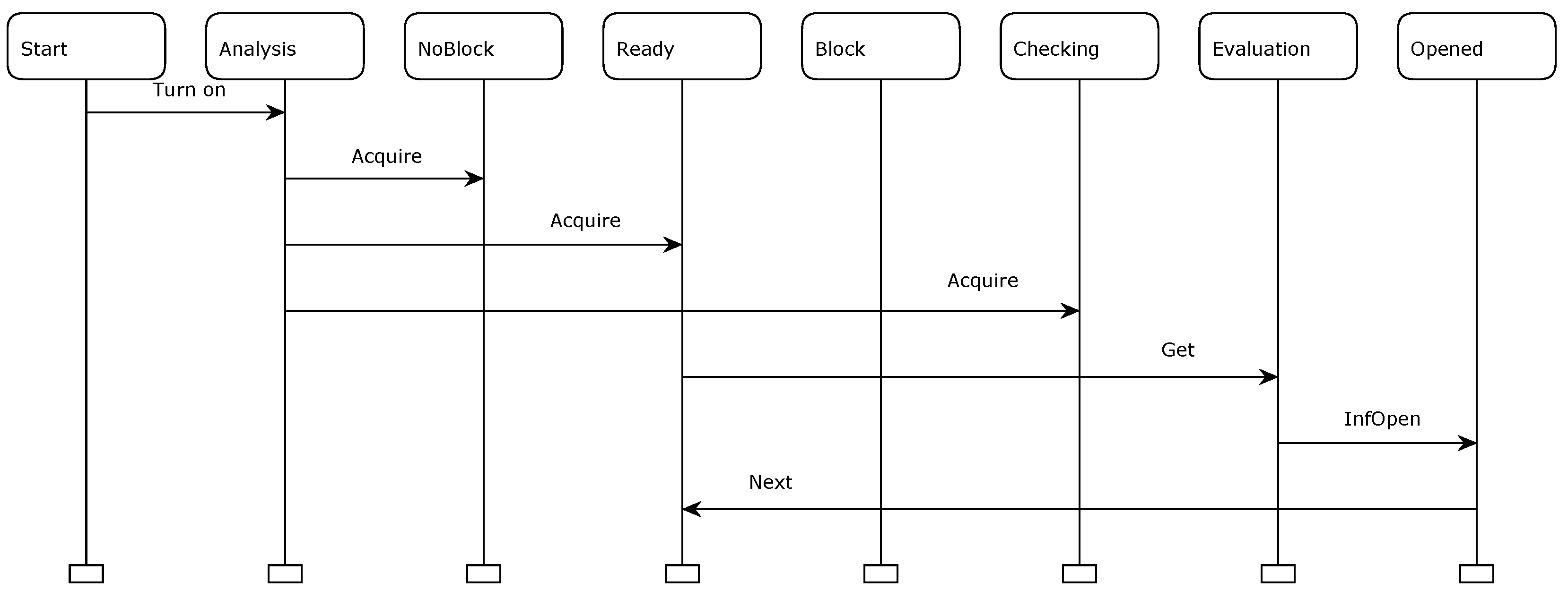
Figure 20.
Message Sequence Chart of Counterexample 1.
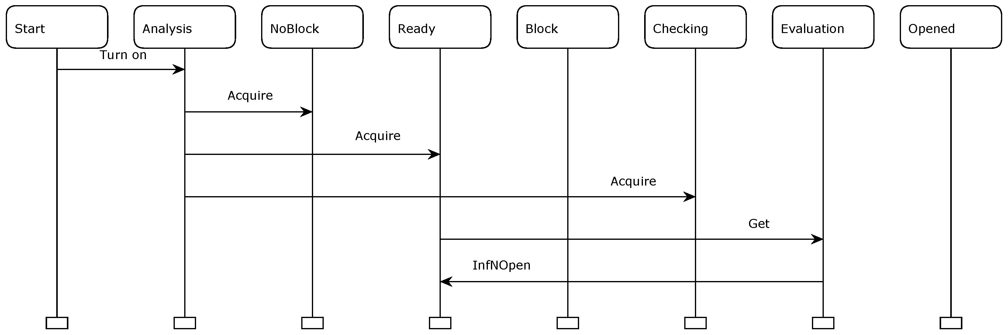
Figure 21.
Full State Space.

| Declarations for 1 Breaker Opening Supervision | |||
| Name | Type | Definition | Meaning |
| iedboot | val | 20 | Estimated time in seconds to the IED boot |
| tmr | val | 1 | Timer value in seconds |
| n | val | 2 | Value used to define Breaker 2 |
| IB | Colset | int with 1..iedboot | Integer data from 1 to iedboot |
| A | Colset | with a | Logical data |
| BOOL | Colset | bool | Boolean data |
| BR | Colset | index br with 2..n | Data to define breakers |
| BRxBOOL | Colset | product BR*BOOL | Product data BRxBOOL |
| BRxBOOLxBOOL | Colset | product BR*BOOL*BOOL | Product data BRxBOOLxBOOL |
| INT | Colset | int | Integer data |
| TIMER | Colset | int with 1..tmr | Integer data from 1 to tmr |
| c, g, h | var | BOOL | Boolean variables |
| ib | var | IB | IB variable |
| t | var | TIMER | TIMER variable |
| b | var | BR | BR variable |
Table 2.
Meaning of places and transitions in Figure 15.
Table 2.
Meaning of places and transitions in Figure 15.
| Page Initiating for 1 Breaker Opening Supervision | ||
| Element | Type | Meaning |
| Start | Place | A token a in this place indicates the 1 breaker opening supervision needs to be started |
| Analysis | Place | According to the information which “authorizes” to start 1 breaker opening supervision, there is a token in this place if the supervision must be started or a token if the supervision must not be started |
| NoBlock | Place | A token a in this place means there is no block pre-condition to the 1 breaker opening supervision |
| Ready | Place | A token in this place means the 1 breaker opening supervision is ready to start |
| Block | Place | A token a in this place means the 1 breaker opening supervision is blocked and supervision can not be achieved due to reliability criteria of the proposed code approach |
| Checking | Place | A token a in this place means some posterior checking needs to be done from this point |
| Turn on | Transition | A token a in place Start enables this transition. When this transition fires, after a timer , if the 1 breaker opening supervision must be started, an information is returned from HPP. Otherwise, an information is returned from HPP. The boolean logical function associated to this transition, , is described by , where is the boolean logical function associated to the pre-condition “Analysis" of the PV IED status |
| Acquire | Transition | This transition evaluates the obtained information about the ”authorization” to start the 1 breaker opening supervision. This information is needed to start the execution in a reliable way. The place Analysis enables this transition. If the supervision must be started, a token is in place Analysis. In this condition, when this transition fires, a token is added to the place Ready. Moreover, a token a is added to the place NoBlock and a token a is added to the place Checking, indicating there is no block pre-condition to the supervision and some posterior checking needs to be done from this point respectively. On the other hand, if the supervision must not be started, a token is in place Analysis. In this condition, when this transition fires, a token a is added to the place Block, indicating a block of the supervision and supervision can not be achieved due to reliability criteria of the proposed code approach |
Table 3.
Meaning of places and transitions in Figure 16.
Table 3.
Meaning of places and transitions in Figure 16.
| Page Evaluating for 1 Breaker Opening Supervision | ||
| Element | Type | Meaning |
| Ready | Place | See Table 2 |
| Evaluation | Place | This transition evaluates 1 breaker status. When the transition Get fires, there is a token in this place if the breaker is opened or a token if the breaker is not opened |
| NoBlock | Place | See Table 2 |
| Opened | Place | After transition InfOpen to fire, there is a token in this place if the breaker is opened |
| Get | Transition | A token in place Ready enables this transition, indicating the 1 breaker opening supervision is ready to start. When this transition fires, if the breaker is opened an information is returned from HPP. Otherwise, an information is returned from HPP. The boolean logical function associated to this transition, , is described by , where is the boolean logical function associated to the pre-condition breaker status |
| InfNOpen | Transition | A token in place Evaluation enables this transition. When this transition fires, a token is removed from place Evaluation and a token is added to the place Ready |
| InfOpen | Transition | A token in place Evaluation enables this transition. When this transition fires, a token is removed from place Evaluation and a token is added to the place Opened |
| Next | Transition | A token in place Opened enables this transition. When this transition fires, a token is removed from place Opened, a token is added to the place Ready and a breaker opening supervision alarm is generated |
Table 4.
Meaning of places and transitions in Figure 17.
Table 4.
Meaning of places and transitions in Figure 17.
| Page Impeding for 1 Breaker | ||
| Element | Type | Meaning |
| Checking | Place | See Table 2 |
| NoBlock | Place | See Table 2 |
| Block | Place | See Table 2 |
| ImpCheck | Transition | This transition evaluates if there is a condition which impedes 1 breaker opening supervision. A token a in place Checking and a token a in place NoBlock enable this transition. When this transition fires, after a timer t, if there is a condition which impedes 1 breaker opening supervision, an information is returned from HPP. Then, a token a is removed from place Checking, a token a is removed from NoBlock and a token a is added to the place Block, indicating a block of the 1 breaker opening supervision. On the other hand, if there is no condition which impedes 1 breaker opening supervision, an information is returned from HPP. Thus, a token a is removed from place Checking and a token a is added to the place Checking, enabling transition ImpCheck. The boolean logical function associated to this transition, , is described by , where is the boolean logical function associated to the pre-condition breaker impeding |
Table 5.
Value and Colour Specifications Adjustments for 4 Breakers.
| Declarations for 4 Breakers Opening Supervisions | |||
| Name | Type | Definition | Meaning |
| n | val | 4 | Value used to define Breakers 1, 2, 3 and 4 |
| BR | Colset | index br with 1..n | Data to define breakers |
Table 6.
Conditions with pre-conditions, variables and values to case 1 (OPENED).
| Conditions to Case 1 (OPENED) | ||
| Pre-Conditions | Variables | Values |
| Energized IED | Data.IEDEnergized | 1 |
| IED Communication | Data.IEDCommunication | 1 |
| Ready IED | Data.IEDReady | 1 |
| Breaker 2 | Data.BR2.Status | 0 |
Table 7.
Conditions with pre-conditions, variables and values to case 2 (NOT OPENED).
| Conditions to Case 2 (NOT OPENED) | ||
| Pre-Conditions | Variables | Values |
| Energized IED | Data.IEDEnergized | 1 |
| IED Communication | Data.IEDCommunication | 1 |
| Ready IED | Data.IEDReady | 1 |
| Breaker 2 | Data.BR2.Status | 1 |
Table 8.
Conditions with pre-conditions, variables and values to case 3 (FAULT).
| Conditions to Case 3 (FAULT) | ||||||||
| Pre-Conditions | Variables | Values | ||||||
| Energized IED | Data.IEDEnergized | 0 | 0 | 0 | 0 | 1 | 1 | 1 |
| IED Communication | Data.IEDCommunication | 0 | 0 | 1 | 1 | 0 | 0 | 1 |
| Ready IED | Data.IEDReady24 | 0 | 1 | 0 | 1 | 0 | 1 | 0 |
| Breaker 2 | Data.BR2.Status | X | X | X | X | X | X | X |
Disclaimer/Publisher’s Note: The statements, opinions and data contained in all publications are solely those of the individual author(s) and contributor(s) and not of MDPI and/or the editor(s). MDPI and/or the editor(s) disclaim responsibility for any injury to people or property resulting from any ideas, methods, instructions or products referred to in the content. |
© 2024 by the authors. Licensee MDPI, Basel, Switzerland. This article is an open access article distributed under the terms and conditions of the Creative Commons Attribution (CC BY) license (https://creativecommons.org/licenses/by/4.0/).
Copyright: This open access article is published under a Creative Commons CC BY 4.0 license, which permit the free download, distribution, and reuse, provided that the author and preprint are cited in any reuse.


