
Submitted:
31 May 2024
Posted:
03 June 2024
You are already at the latest version
Abstract
Hydrodynamic resistance is a critical parameter in microfluidics, affecting device functionality and performance. However, quantifying hydrodynamic resistance in microfluidics is a challenge due to many influencing factors and the difficulties associated with the precise measurements of low flow rates (< 10 L/min) and pressure drops (< 5 kPa). This article presents a simple experimental test method for assessing hydrodynamic resistance, correlating with theoretical and numerical calculations. The results demonstrate good agreement between benchtop and theoretical data, suggesting a potential standardized method for assessing hydrodynamic resistance in microfluidic devices.
Keywords:
hydrodynamic resistance
; microfluidics
; differential pressure
; metrology
; test method
1. Introduction
Hydrodynamic resistance, sometimes referred to as flow resistivity, is a critical parameter in microfluidics, as high levels can lead to high pressures, increased costs, and reduced device performance. High hydrodynamic resistance also leads to high shear stress, which is generally unwanted in devices handling fluids containing biological materials. To address these challenges, controlling and accurately measuring hydrodynamic resistance is essential. Despite the importance of understanding hydrodynamic resistance, microfluidics as a field has not agreed upon definitions, hierarchical lists of important factors and contributions, and analytical methods for understanding flow resistance in microfluidic chip. This study aims to provide solutions to address this gap.
Measurements of hydrodynamic resistance are performed to determine the pressure required to achieve a desired fluid flow rate through a microfluidic system, or conversely, to determine the flow rate corresponding to a given inlet pressure. Hydrodynamic resistance measurements typically involve measuring the differential pressure (or inlet pressure) across a microfluidic system and the flow rate through the same pathway, either simultaneously or sequentially, at multiple operating conditions. The output of this test can be a table of hydrodynamic results and/or a graphical representation of flow vs. pressure, ideally spanning the entire operating range of the device. Hydrodynamic resistance can be expressed in units of Pa∙s/m3.
This article makes use of the definition of hydrodynamic resistance stated in the MFMET activity A2.2.2 report [1] and whitepaper by Copeland et al. [2]. Hydrodynamic resistance describes a relationship between a volumetric flow in a fluid conduit and the pressure difference that is necessary for driving it. The Hagen-Poiseuille equation describes such a relationship for a steady-state flow in a long cylindrical pipe where the fluid is incompressible, Newtonian, and in the laminar flow regime [3]. In accordance with the Hagen-Poiseuille equation, hydrodynamic resistance is defined as the ratio of the pressure differential and the volumetric flow [1,2]:
Here Δp is the pressure differential, Q is the volumetric flow rate, and RH represents hydrodynamic resistance. By rearranging eq. 2, the hydrodynamic resistance is then given as
The objective of this article is threefold – 1) to describe different hydrodynamic resistance quantification methods, 2) compare these methods in a case study by measuring the resistance offered by a microfluidic system, and 3) compare those experimental results against established computational and analytical methods to assess the feasibility of using computational methods to predict the fluid dynamics in the microscale.
A survey of flow control in microfluidics, comprising hundreds of responses from microfluidic contacts of the enablingMNT organization, found that the most common flow rates used are 1 – 100 µL/min [4]. Seeking relevance for broad and common applications, this study aims for flow rates within this range, and adjusts the driving pressure differential accordingly. The methods and results presented in this article are crucial when considering a holistic view of the chip, as they shed light on the intricate relationships between chip design, material and reagent selection, and fabrication nuances. This work establishes a foundation for addressing the complex engineering challenge of integrating these microfluidic factors to achieve a practical solution.
2. Experimental Test Method
2.1. Test Method
The hydrodynamic resistance across a microfluidic device can be measured using pressure sources or controllers, flow sensors (F), pressure sensors (P) and tubing. Four representative setups to measure hydrodynamic resistance are represented in Figure 1.
Configuration B, which features a pressure sensor integrated within the pressure controller and a flow sensor before the microfluidic device, has been chosen for its simplicity and ease of implementation. This setup requires only one flow sensor and one pressure sensor, reducing the risk of leaks and system complexity. Additionally, the reduced tubing configuration minimizes the risk of leaks and improves the overall system compliance (elasticity).
2.2. Geometry
The simulated geometry consists of a square cross section channel with dimensions 100 µm × 100 µm. The channel is fabricated with circular cross section transversal inlet and outlet wider cylindrical connector cups to connect the tubing. The microfluidic path is composed of five parts as depicted in Figure 2. They are: a - cylindric connection for supply tubing, b - cup connector before the channel inlet, c - channel of square cross section, d - cup connector after the channel outlet, and e - cylindrical connector for exhaust tubing.
The length of the setup from one axis of the connector cup to the other is 18 mm (Figure 2i. Since the distance of the connector cup axis from the microchannel inlet is 0.25 mm the length of the microchannel itself is 17.5 mm. The connector cup is shown in detail in Figure 2ii. The dimensions of each of the elements are detailed in Figure 2iii.
2.3. Setup and Test Equipment Recommendations
To facilitate the implementation of microfluidic setups, a list of recommendations has been compiled and is presented below.
Pressure controllers/regulators are crucial components in microfluidics to regulate and maintain precise pressure levels within microfluidic systems. There are three main working principles of pressure controllers/regulators commonly used in microfluidics: pneumatic, piezoelectric and electronic.
Pneumatic pressure regulators control pressure by adjusting the flow of gas (usually air) into the microfluidic system. These regulators are often used in microfluidic setups where the pressure needs to be controlled precisely. They are suitable for applications like droplet generation, cell manipulation, and microreactors. Pneumatic regulators offer fast response times, high precision, and the ability to maintain stable pressures over extended periods.
Piezoelectric pressure controllers use piezoelectric materials to generate precise mechanical displacements when voltage is applied. These displacements are used to adjust pressure within the microfluidic system. They are commonly used in microfluidic setups for applications such as microvalve control, flow rate regulation, and pressure-driven microfluidic systems. Piezoelectric pressure controllers are known for their high precision and responsiveness. They can be used for fine adjustments and are suitable for applications where rapid changes in pressure are required.
Electronic pressure regulators (EPR) use electronic components to control pressure, often by regulating the opening and closing of valves or adjusting pump speed. EPR are versatile and can be used in various microfluidic applications, such as sample injection, chromatography, and pressure-driven flow control in microchannels.
A suitable pressure controller should be chosen that is capable of generating the admissible pressure range in the microfluidic device. Generally, a pressure controller should be used between 10% and 100% of its pressure range capability. The minimum pressure generated by the pressure controller is generally at least 100 mbar to ensure good pressure control and stability.
The stability of the pressure controller must coincide with the accuracy required for the pressure differential, or hydrodynamic resistance measurement. This information should be provided in the datasheet of the pressure controller in percentage of the flow value or flow rate units. Note that the stability can be impacted by the compliance of the entire system and by dead volumes which can entrap air (in the case of a liquid as the test media) and dampen any pressure pulses.
A sufficient pressure level at the pressure source (inlet) of the pressure controller should be provided so that the microfluidic device can function as intended. The minimum and maximum achievable pressure level, as well as the electrical power requirements, should be provided in the datasheet of the pressure controller.
The pressure controller should be at the same height as the microfluidic device to eliminate pressure differences due to the hydrostatic pressure head.
Pressure and flow sensors should be chosen according to the expected range over which the microfluidic device will be operated. Generally, the sensor should be used between 10% and 100% of its pressure range capability.
The accuracy of the sensor should correspond to the accuracy required for the pressure drop, flow or hydrodynamic resistance measurement. Typically, this information can be found in the datasheet of the sensor. Again, the accuracy of the sensor can be negatively impacted by the compliance of the entire test system, including dead volumes that can entrap air in the liquid used as the test media.
To ensure precise results, the pressure sensors should be positioned at the same height as the microfluidic device. When a liquid is used as the test medium, the tubing connecting the pressure sensor to the pressure controller and microfluidic device should be oriented downward so that air bubbles can be expelled or purged downstream of the test system. When a gas is used as the test medium, the tubing connecting the pressure sensor to the pressure controller and microfluidic device should be oriented upward so that liquid droplets (potentially due to condensation of humidity) are expelled or purged downstream of the test system.
All pressure sensors should be calibrated over the expected operating range of the device under investigation in a ISO 17025:2017 accredited laboratory.
Fittings and connectors should be chosen based on their labeled pressure rating, since leakage will introduce measurement errors and will decrease the accuracy of the hydrodynamic resistance measurement. Additionally, the dead volume should be minimized for all fittings and connectors used within the test system.
2.4. Test Conditions and Preparation
Measurements should be performed in a temperature- and humidity-controlled environment. The temperature, ambient pressure, and humidity range should be known, either by measurement using calibrated sensors or by knowledge of the control ranges, since these measurements may be impacted by the environmental conditions. Ideal conditions are 23 ± 2 °C (room temperature) and 55 ± 5% humidity.
All elements of the test setup (pressure controller, measurement sensors, test media, tubing, and microfluidic device under investigation) should be placed in the room where the tests are to be performed, at least 24 h before testing to ensure thermal equilibrium of the microfluidic system within a well-controlled environment indicative of its intended use. Electrically powered elements such as the pressure controllers and pressure sensors should be powered on at least 30 min before beginning any measurement. For systems containing a reservoir, the reservoir should be filled at least 30 min before making any measurement. The entire system, including pressure taps in the case of a differential pressure sensor, should be purged before taking any measurements. Purging or priming the test system can be performed using the test media at the maximum allowable pressure of the pressure controller/pressure sensor/microfluidic device, limited by the component which has the lowest maximum labeled pressure. Note that the outlet of the stainless-steel pipe at the outlet of the flowmeter is equipped with the same fittings and kept at the same height as for the measurement with and without chip.
2.5. Test Protocol
After ensuring all requirements from Section 2.1, Section 2.2 and Section 2.3 are met, the procedure suggested and validated in this work to obtain hydrodynamic resistance of a microfluidic device is as follows:
- Prepare all equipment to be used.
- Connect all test elements together and secure the test setup, making sure that all fittings and interconnections are correctly and tightly connected.
- If necessary, fill the reservoir with the test fluid medium at least 30 min before beginning the tests.
- Connect all required electrical power supplies to the pressure controllers and sensors, and turn on all instrumentation at least 30 min before beginning the tests.
- Prime the test setup using the test media at the maximum admissible pressure, limited by the component (pressure controller, pressure sensors, microfluidic device) which has the lowest maximum labeled pressure.
- Zero the pressure and flow sensors to minimize measurement offsets.
- Set a target pressure for the pressure controller and observe the rise and stabilization of the pressure reading using the pressure sensors.
- After a stable pressure is reached (not drifting upwards of downwards within the stability stated in the pressure controller datasheet), record the measurement of pressure, differential pressure, or flow rate, if possible digitally, to allow higher sampling rate, reducing the effect of collection time impact on a time-averaged pressure value.
- Repeat step 7 and 8 for all the required target pressure, differential pressure or flow rate, encompassing all the operating conditions at which the microfluidic system will be used.
- Additional measurements should be equally carried out at each operating condition without the microfluidic device in the test system. These control tests will serve to measure the pressure differential associated with the location of the pressure taps and the overall setup supporting the experiment.
- Calculate the hydrodynamic resistance associated with each test condition according to eq. 2. The pressure drop associated solely with the experimental setup without the microfluidic device (control) should be subtracted from the test conditions with the microfluidic device (total) to determine the pressure drop within the microfluidic device itself (eq. 3).
In addition, hydrostatic pressure corrections in case of vertical installations (e.g., different height between the pressure sensor(s) and the device under test), and/or capillary pressure elimination (e.g., in case of water freely dripping from an outlet) should be applied.
Finally, to assess a representative assessment of the repeatability and reproducibility of the measurements, several measurement iterations should be performed on the same device under test. Typically, a range of five to thirty repetitions is performed to obtain a statistically representative distribution of measurements. To assess the reproducibility of the hydrodynamic resistance expected for a set of microfluidic devices, the entire measurement procedure should be performed on a set of five to thirty devices under the same environmental conditions and with the same instruments and operator.
2.6. Implementation of the Test Protocol
The test protocol developed within 20NRM02 MFMET project [5] and presented in Section 2.4 was implemented as follows: the device under investigation was a "Fluidic 157" microfluidic chip provided by Microfluidic ChipShop [6]. The microfluidic device material is comprised entirely of Topas (Topas is a COC – cyclic olefin copolymer – resin). Each chip contains 8 identical, parallel channels of 100 µm width, 100 µm depth, and 18 mm length, and an overall footprint of 75.5 mm × 25.5 mm, coincident with the standard dimensions of a microscope slide.
The chip has luer fluidic interfaces (female mini luer ports), integrated directly onto it. At the inlet port of the device under investigation, a luer male to threaded adapter (item #P-683-01, Upchurch Scientific) with an additional threaded female-female elbow (items #P-430, Upchurch Scientific) and flangeless nut (item P-235, Upchurch Scientific), were used to connect the fluidic path to the microfluidic chip. All tubing used to connect the different components of the setup, from the pressure controller to the device under investigation, were 316L stainless steel 1/16" OD tubes for a total length of 30 cm.
Figure3a shows a schematic of the microfluidic device used. The illustrative drawing of the test setup mounted to assess the Fluidic 157 microfluidic device is presented in Figure 3b.
Figure 3c,d show the test setup and a close-up view of the microfluidic channel under investigation, respectively. The hydrodynamic resistance test setup (Figure 3c) used the one ressure controller (Elveflow OB1 MkII). The 0-200 mbar channel of the pressure controller was pre-calibrated and used to control and measure pressure readings. One of two flow sensors (≤ 3 µL/min full range, ML120 plus FlowPlot software, Bronkhorst; ≤ 7 µL/min full range, MFS 2 plus ESI software, Elveflow) were used. The temperature, humidity, and ambient pressure of the environment in which the device was tested were measured with a thermo- ygro-barometer (ROTRONIC LOG-HC2-P1/HC2-C05). All instruments were calibrated over their full operating ranges in accordance with the metrological national primary standard at CETIAT or by ISO 17,025 accredited laboratories.
The fluid used for these tests was ultra-pure degassed water filtered at 0.2 µm (≤ 0.06 µS/cm, 998.2 kg/m3, 1.002 mPa·s, at 20 °C).
To assess the hydrodynamic resistance of the microfluidic channel, both flow and pressure were measured in the system with and without the device under investigation at 5 inlet pressures (1.50, 2.05, 2.50, 3.20, 3.90 kPa). The hydrodynamic resistance could then be determined for the entire system, the test setup without the microfluidic chip in it, and the microfluidic channel by itself (by calculating the difference between the two circuits).
All average measurements of pressure and flow were repeated two times. The measurement uncertainties have been evaluated according to GUM [7] using the law of propagation of uncertainty including calibration, reading, and repeatability uncertainty sources. In this case, the differential pressure is calculated as the measured pressure (at the pressure sensor location) minus the measured atmospheric pressure. The pressure was zeroed prior to testing to account for any discrepancies associated with the hydrostatic pressure head. The associated hydrodynamic resistance was calculated as the ratio of the mean pressure step value (difference between two consecutive values of differential pressure) over the corresponding mean flow rate step value (difference between two consecutive values of flow rate) for each step. The resulting resistivity was then obtained by averaging over the steps. In this procedure, possible constant offsets in differential pressure and flow rate are canceled. The relative expanded uncertainty on the hydrodynamic resistance was calculated as the square root of the quadratic sum of the pressure and flow measurement uncertainties. The final uncertainty of the averaged value of hydrodynamic resistance contains also the corresponding standard deviation of the averaged data (repeatability).
3. Theoretical Calculation of Hydrodynamic Resistance
Hydrodynamic resistance, assuming incompressible fluid, unidirectional flow and steady state, can be analytically obtained using eq. 2 for a microchannel with a square cross-section [2]. The equation was derived by solving the Navier-Stokes equation with no slip boundary condition at the conduit walls. In a particular case of a square cross section (square cross section is a particular case of rectangular cross section where W (width) = H (height)) with length L >> H, White (1991) [8] presents the pressure drop on a channel over a given length y as
Bruus reorganizes this equation to calculate the hydrodynamic resistance theoretically [3], substituting the conduit width w = height h, to describe the flow in a square channel:
Eq. 4 and 5 contain an infinite series, where the terms have a factor decreasing as 1/n5 for increasing odd integers n. Bruus states that this relation results in an error of 13 % in hydrodynamic resistance for the case were h = w. If the only term considered is n = 1, and the approximate numerical values 192/π5 ≈ 0.63 and tanh(π/2) ≈ 0.917 are substituted in eq. 5, one finds eq. 6 [2].
It is additionally assumed that the Reynolds number is small (< 10); that only a small fluid mass per distance unit is used, so gravity can be considered negligible; and that all other sources of resistance besides the 100 µm x 100 µm cross section of the channel contribute negligibly to the overall hydrodynamic resistance in the microfluidic system.
4. CFD Simulations of Hydrodynamic Resistance
Computational fluid dynamics (CFD) simulations of the flow in the microfluidic chip were performed using Comsol Multiphysics V5.2 and OpenFOAM to obtain the simulated hydrodynamic resistance. This served as comparison from simulated to analytical and experimental results, but also to study the possible influence of using different CFD setups to the simulated result. The flow was simulated based on the Navier Stokes equations considering Newtonian, incompressible fluid and assuming laminar and stationary flow. Boundary conditions at the walls were set as no-slip. Properties of the fluid (water) were set at 20 °C as imposed in the experiments. The output of the CFD simulations was either a volumetric flow rate for a given differential pressure between the two ends of the geometry (Comsol) or the differential pressure for a given volumetric flow rate (OpenFOAM).
In Comsol, the Microfluidics module with physics-controlled mesh was used to solve the flow velocity and pressure field. MUMPS solver combined with GMRES solver for fluid flow variables were used. Mesh elements were set through a physics-controlled mesh composed by 3,717,915 tetrahedron, 5648 pyramid, 325,564 prism, 219,956 triangle, 2508 quad, 8135 edge element and 74 vertex elements. Fixed inlet and outlet pressure boundary conditions were imposed, and several simulations were performed for various inlet-outlet pressure differences ranging from 1 kPa to 5 kPa.
In OpenFOAM, the simpleFoam solver was used and a hexahedral mesh with density of 40 × 40 cells in the microchannel cross section was selected based on a mesh convergence study. Total number of cells in the complete geometry was 15 168 000 and no boundary refinement was used because the flow is laminar. A constant value of flow velocity (piston profile) was prescribed at the inlet and several simulations were performed for different inlet velocities corresponding to flow rates from 15.7 µL/min to 38.9 µL/min. Zero velocity gradient condition was used at the outlet and for pressure the zero gradient was used at the inlet and at the wall while a fixed value at the outlet.
5. Results and Discussion
Table 1 shows the experimental results used in the calculation of the hydrodynamic resistance, obtained for Configuration B (Figure 1ii) from the pressure sensor to the outlet of the device under test. Flow and pressure measurements were acquired synchronously at a 50 Hz sampling frequency for 180 s for each plateau at decreasing and increasing pressure and flow steps to include hysteresis effect in the overall hydrodynamic resistance evaluation. The average expanded relative uncertainty on the differential pressure measurement is 0.55% (k=2, with k the coverage factor, and k=2 indicates approximately 95% confidence), and the average expanded relative uncertainty on the flow rate measurement is 2.31% (k=2).
Table 2 shows the experimental results obtained for the measurement of the circuit without chip (control setup). The uncertainties on pressure and flow rate measurements were obtained in a similar manner as to the ones obtained for the setup with the microfluidic chip.
The volumetric flow rate is lower when the microfluidic chip is connected to the setup (Table 1) compared to when it is not (Table 2), for the same pressure drop . Also, the hydrodynamic resistance is greater when the microfluidic chip is connected to the setup, compared to when it is not. Most of the flow resistivity is associated with the microfluidic chip, which is expected considering that the 100 µm × 100 µm microchannel is the smallest flow path cross section of the system.
The hydrodynamic resistance of the microfluidic chip under test is obtained by subtracting the hydrodynamic resistance obtained for the control setup from that of the entire circuit with the microfluidic chip. An average experimental value of 5.63∙1012 Pa∙s/m3 was obtained for the microfluidic chip under investigation across all test conditions, with an overall associated expanded relative uncertainty of 42.8 % (k=2).
This value of expanded relative uncertainty is quite high. This is possibly due to the terms included in the calculations not yet being validated for a microfluidic experiment. This was previously seen on the calculation of uncertainty of the volumetric flow rate in microchannels [9]. Nonetheless, this first step to obtain an average experimental value, although associated with a relatively high relative uncertainty of 42.8 %, demonstrates the viability of the proposed methodology.
Using eq. 6 the hydrodynamic resistance of 4.97∙1012 Pa∙s/m3 is obtained, to which the result from eq. 5 approximates (RH=4.98∙1012 Pa∙s/m3). The relative difference between both hydrodynamic resistances calculated is <1 %. The hydrodynamic resistance calculated from the CFD simulation with the straight microchannel (no connector cups) was RH = 5.00 × 10¹² Pa.s/m3 deviating from the analytical prediction by 0.4 %.
The results of the simulations of the complete microchannel with connector cups are summarised in Figure 4 where the flow rate dependence of the resulting hydrodynamic resistance is shown.
We see that the CFD prediction of the hydrodynamic resistance of the microchannel with connector cups is lower than the experimental result by 7.9 % in case of OpenFOAM and by 6.4 % in case of COMSOL. The analytical prediction which considers the straight square cross section channel only (without the connector cups) is 12 % lower than the experimental value. Silverio & Cardoso present a discussion of microfluidic systems and their associ-ated flow, which covers several effects such as surface tension forces, conduit wall friction, and pressure drops due to contraction and expansion [10]. The theoretical calculation for flow resistivity does not take these effects into account, and it is possible that one or more of these effects are the cause of the discrepancy between experiment and theory. Indeed, Silverio & Cardoso state that entrance effects, i.e., the contraction and expansion at the entrance and exit of a microfluid channel, may account of as much as 30 % of the total pressure drop [10], which is sufficient to explain the observed relative discrepancy of 12 %. Nonetheless, the observed maximum 12 % discrepancy between experimental and theoretical values is deemed not significant within the context of the overall uncertainty, affirming the reliability of the study’s findings.
Comparison of results for hydrodynamic resistance obtained by various methods – experimental (Section 2), analytical (Section 3) and simulations (Section 4) is given in Table 3.
The test setup shown in Figure 1ii (Configuration B), characterizes the hydrodynamic resistance from the outlet of the pressure controller to the outlet of the microfluidic chip or outlet of the test setup. The flow pathway of the system contains not only the microfluidic chip under investigation, but also 1/16’’ tubing, fittings, and the flow sensor. This report presents a step-by-step methodology for how to accurately make hydrodynamic measurements in a microfluidic path and calculate the hydrodynamic resistance associated only with the microfluidic device under investigation. Most of the hydrodynamic resistance is associated with the microfluidic chip, which is expected considering that the 100 µm x 100 µm microchannel is the smallest flow path cross section of the system.
Despite most of the hydrodynamic resistance being associated with the microfluidic chip, the contributions to the hydrodynamic resistance from the flow sensor, tubing, and fittings are still large enough to significantly affect the total hydrodynamic resistance.
These findings highlight the importance of considering the hydrodynamic resistance associated with all the fluid-contacting components of the system under test. This result gives light to the importance of standardization to accurately determine the hydrodynamic resistance of microfluidic devices.
6. Conclusions
The study presented details a comprehensive methodology for accurate measurement of hydrodynamic resistance in a microfluidic chip setup. The experimental results, encompassing measurements from the pressure sensor to the outlet of the device under test, reveal an average hydrodynamic resistance of 5.63∙1012 Pa∙s/m3, subject to an overall expanded relative uncertainty of 42.8 % (k=2). This uncertainty analysis, conducted in accordance with the Guide to the Expression of Uncertainty in Measurement (GUM), underscores the rigor applied in assessing measurement uncertainties, including calibration, reading, and repeatability sources. The high value of 42.8 % highlights the importance of accounting for the correct terms in uncertainty calculation of hydrodynamic resistance in microfluidic devices to ensures accurate prediction of fluid flow and pressure drop, which is critical in applications such as lab-on-a-chip, biomedical devices, and pharmaceutical processing, where small variations in flow rates can have significant consequences.
Comparison with theoretical values, indicates a 12 % deviation from an analytical formula and even lower deviations from CFD computations, which falls within an acceptable range given the associated uncertainty. Furthermore, the study extends its analysis to include a control setup without the microfluidic chip. Despite most of the hydrodynamic resistance being attributed to the microfluidic chip, the interconnected components, such as tubing, fittings, and the flow sensor, significantly contribute to the overall hydrodynamic resistance.
The presented test protocol, provides a standardized framework for measuring hydrodynamic resistance in microfluidic devices. The study emphasizes the importance of considering the contributions of all fluid-contacting components within the test system, highlighting their substantial impact on the total hydrodynamic resistance. This research contributes valuable insights to the field of microfluidics, offering a robust approach to hydrodynamic resistance characterization and encouraging further refinement in measurement techniques.
Author Contributions
software, Jan Sluše, Jan Geršl and Vania Silverio, writing—original draft preparation, Florestan Ogheard, Jan Geršl and Vania Silverio, Jose A. Wippold.; writing—review and editing, Florestan Ogheard, Thomas Schrøder Daugbjerg, Jan Geršl, Vania Silverio, and Jose A. Wippold. All authors have read and agreed to the published version of the manuscript.
Funding
This project (20NMR02 MFMET) has received funding from the EMPIR programme co-financed by the Participating States and from the European Union’s Horizon 2020 research and innovation programme. V.S. would like to acknowledge the FCT, I.P., for funding of the Research Unit INESC MN (UID/05367/2020) through pluriannual BASE and PROGRAMATICO and project LA/P/0140/2020 of the Associate Laboratory Institute for Health and Bioeconomy – i4HB.
Data Availability Statement
Supporting data can be found at the MFMET Zenodo repository: https://zenodo.org/communities/mfmet.
Conflicts of Interest
the authors declare no conflict of interest. The funders had no role in the design of the study; in the collection, analyses, or interpretation of data; in the writing of the manuscript; or in the decision to publish the results.
References
- Copeland, M., Ogheard, F., Batista, E., & Silverio, V. MFMET A2.2.2: Development of test protocols for microfluidic devices. 2023. [CrossRef]
- Copeland, M., Ogheard, F., Batista, E., & Heeren, H. van. Whitepaper flow resistivity testing. 2023. [CrossRef]
- Bruus, H. 2008, Theoretical Microfluidics. Publisher: Oxford University Press.
- van Heeren H. (2015) Results survey on microfluidics flow control https://mfmet.eu/wp-content/uploads/2022/02/2015-Microfluidics-Flow-Control-results-from-survey-enablingMNT.pdf [Accessed 9 November 2023].
- https://MFMET.EU.
- https://www.microfluidic-chipshop.com/catalogue/microfluidic-chips/polymer-chips/straight-channel-chips-microscopy-slide-format/straight-channel-chips-with-eight-parallel-channels-fluidic-157/ [Accessed 22/12/2023].
- BIPM JCGM WG1, GUM - JCGM 100:2008(E) – Evaluation of measurement data — Guide to the expression of uncertainty in measurement.
- White F. M. (1991) Viscous fluid flow, 2nd edition, McGraw-Hill, USA, pp 120, equation 3-48, ISBN 10:0070697132.
- Batista E., Almeida N., Godinho I., Filipe E. (2015) Uncertainty calculation in gravimetric microflow measurements. In Advanced Mathematical and Computational Tools in Metrology and Testing X. 98-104. [CrossRef]
- Silverio, V., Cardoso, S. (2021). Lab-on-a-chip: Systems integration at the microscale. In Drug Delivery Devices and Therapeutic Systems (pp. 63–87). Elsevier. [CrossRef]
Figure 1.
The four configurations (A, B, C, and D) differ in the placement of pressure and flow sensors. i) Configuration A features a single pressure controller, one pressure sensor, and one flow sensor in a straight line, while ii) Configuration B includes a pressure sensor within the pressure controller and a flow sensor before the microfluidic device. iii) Configuration C adds a second pressure sensor at the outlet of the microfluidic chip, and iv) Configuration D features a flow sensor and differential pressure sensor in parallel with the microfluidic device.
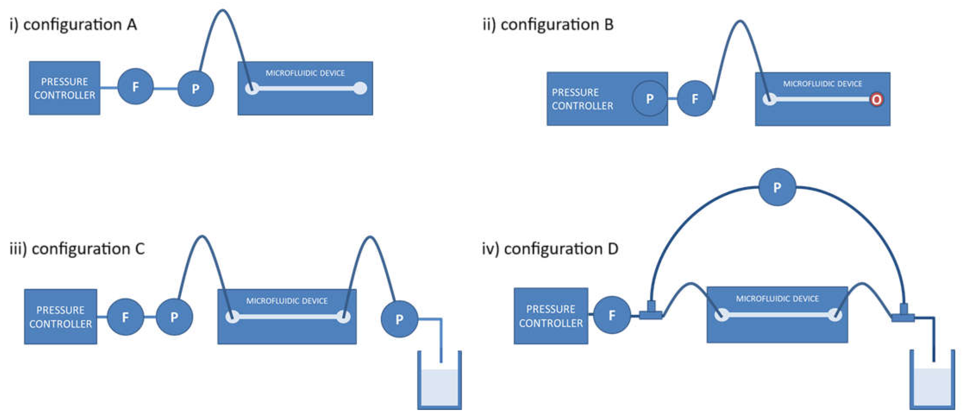
Figure 2.
i) geometry (side view and top view) of the microchannel with the cup elements at both ends, used in the calculations and simulations. ii) Detail of the cylindrical connector cup seen from below. iii) dimensions of the cup connector, in µm. a - cylindric connection for supply tubing, b - cup connector before the channel inlet, c - channel of square cross section, d - cup connector after the channel outlet, e - cylindrical connector for exhaust tubing.
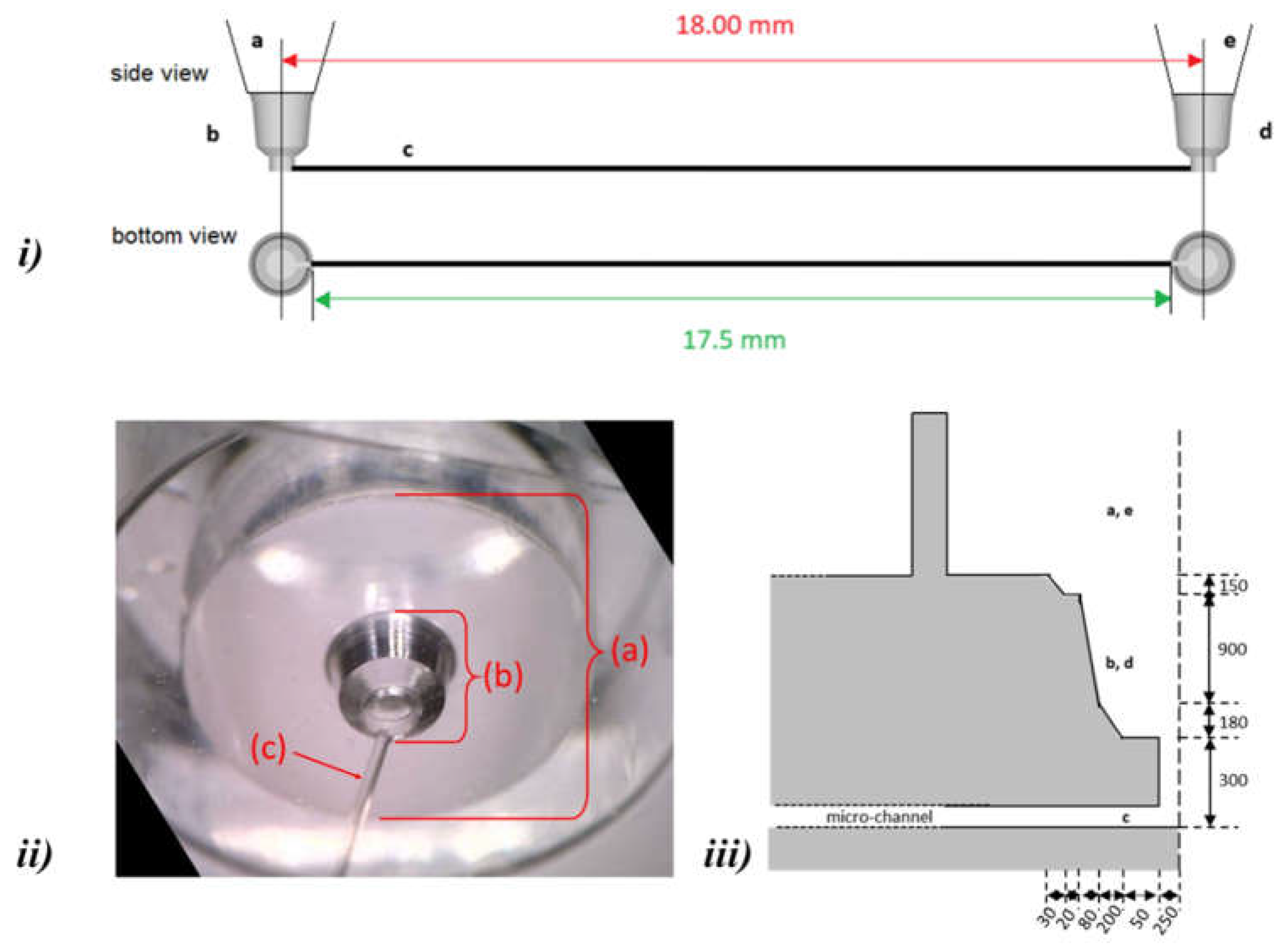
Figure 3.
a) Isometric and top views of Fluidic 157 composed of 8 simple straight channels, with female mini luer ports for fluidic inlets and outlets. b) Schematic of the flow set up used. Images of c) the test setup and d) the chip used in this case study, positioned vertically in relation to the camera lens.
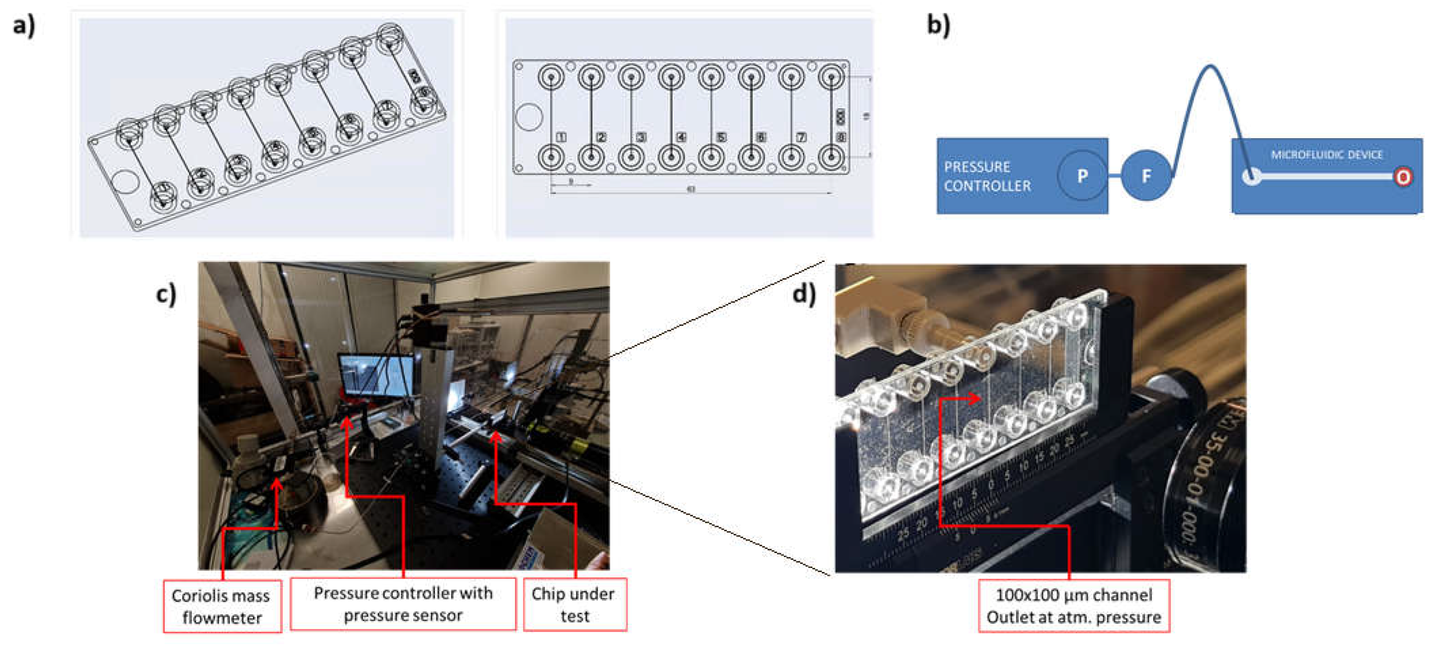
Figure 4.
Hydrodynamic resistance as a function of the flow rate in the microchannel.
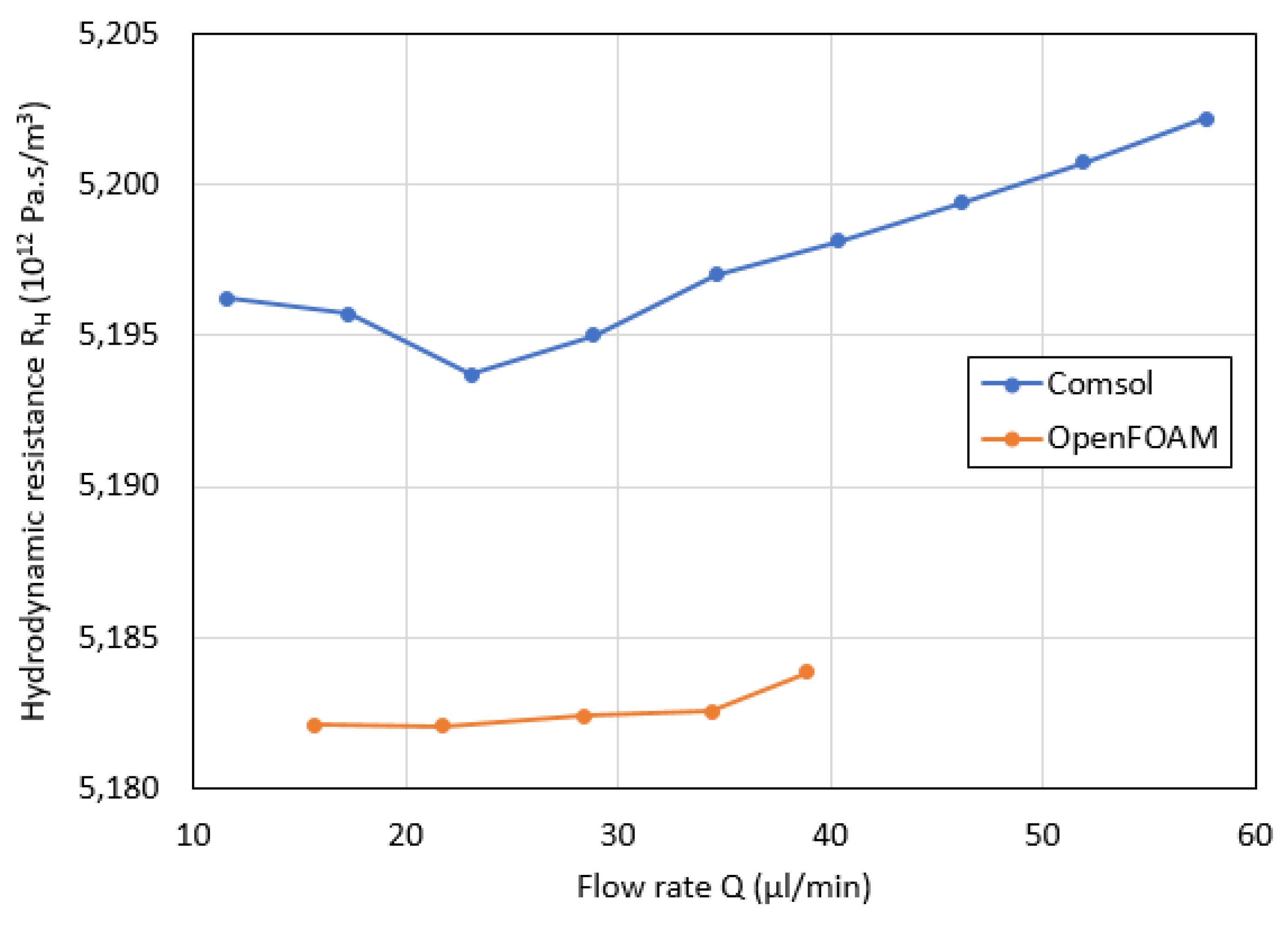

Table 1.
Experimental results with microfluidic chip mounted in Configuration B (Figure 1ii).
Table 1.
Experimental results with microfluidic chip mounted in Configuration B (Figure 1ii).
| Measurements | Calculation (eq. 2) | |||
|---|---|---|---|---|
| 1 | 1 | 2 | 2 | |
| [kPa] | [µL/min] | [kPa] | [µL/min] | [1012 Pa∙s/m3] |
| 3.90 | 18.0 | 3.20 | 14.0 | 10.5 |
| 3.20 | 14.0 | 2.50 | 9.0 | 8.40 |
| 2.50 | 9.0 | 2.05 | 6.0 | 9.00 |
| 2.05 | 6.0 | 1.50 | 2.5 | 9.43 |
| Average | 9.33 | |||
| U (k = 2) | 1.79 | |||
Table 2.
Hydrodynamic resistance calculated from the experimental measurements of volume flow rate after imposing a given differential pressure, in Configuration B (Figure 1ii) without the microfluidic chip (control setup).
Table 2.
Hydrodynamic resistance calculated from the experimental measurements of volume flow rate after imposing a given differential pressure, in Configuration B (Figure 1ii) without the microfluidic chip (control setup).
| Measurements | Calculation (eq. 2) | |||
|---|---|---|---|---|
| 1 | 1 | 2 | 2 | |
| [kPa] | [µL/min] | [kPa] | [µL/min] | [1012 Pa∙s/m3] |
| 3.90 | 57.0 | 3.20 | 48.0 | 4.67 |
| 3.20 | 48.0 | 2.50 | 37.5 | 4.00 |
| 2.50 | 37.5 | 2.05 | 28.0 | 2.84 |
| 2.05 | 28.0 | 1.50 | 18.0 | 3.30 |
| Average | 3.70 | |||
| U (k = 2) | 1.61 | |||
Table 3.
Summary of the hydrodynamic resistances obtained by various methods.
| Setup | Method | RH | Uncertainty |
|---|---|---|---|
| [1012 Pa∙s/m3] | [1012 Pa∙s/m3] | ||
| Circuit Configuration B with chip | experimental measurement | 9.33 | 1.79 |
| Circuit Configuration B without chip – control setup | experimental measurement | 3.70 | 1.61 |
| Chip (Figure 3i, a, b, c, d and e) | calculated from measurements | 5.63 | 2.41 |
| Straight square cross section channel (Figure 3i, c) | eq. 5 | 4.98 | |
| Straight square cross section channel (Figure 3i, c) | eq. 6 | 4.97 | |
| Straight square cross section channel (Figure 3i, c) | COMSOL Multiphysics, $OpenFoam | 5.00 | |
| Chip (Figure 3i, a, b, c, d, e) | COMSOL Multiphysics | 5.27 | |
| Chip (Figure 3i, a, b, c, d, e) | OpenFoam | 5.18 |
Disclaimer/Publisher’s Note: The statements, opinions and data contained in all publications are solely those of the individual author(s) and contributor(s) and not of MDPI and/or the editor(s). MDPI and/or the editor(s) disclaim responsibility for any injury to people or property resulting from any ideas, methods, instructions or products referred to in the content. |
© 2024 by the authors. Licensee MDPI, Basel, Switzerland. This article is an open access article distributed under the terms and conditions of the Creative Commons Attribution (CC BY) license (http://creativecommons.org/licenses/by/4.0/).
Copyright: This open access article is published under a Creative Commons CC BY 4.0 license, which permit the free download, distribution, and reuse, provided that the author and preprint are cited in any reuse.


