Submitted:
31 May 2024
Posted:
04 June 2024
You are already at the latest version
Abstract
In the ongoing transition from fossil fuels to renewable energies, advances are particularly expected regarding safe and cost-effective solutions. Publicising instances of such advances and emphasising safety considerations constitute the rationale for this communication. Knowing that high-strength steels can prove economically relevant for transporting hydrogen in pipelines by limiting the pipe wall thickness required to withstand high pressure, one advance relates to a bench designed for contributing to study the safety of the gaseous transport or renewable-energy-related buffer storage of hydrogen. That bench has been specifically implemented at technology readiness level TRL 6 for testing initially intact, damaged, or pre-notched DN 300/NPS 12, DN 600/NPS 24, and DN 900/NPS 36 pipe sections in order to provide data allowing for the possible validation of fully satisfactory predictive models in terms of hydrogen embrittlement and potential corollary ruin. The other advance relates to the reactivation of a previously fruitful applied research into mass solid-state hydrogen storage through a new public-private partnership. This latest development comes at a time when markets have started driving the hydrogen economy, bearing in mind that phase-change materials decisively allow levelling the heat transfers during the absorption/melting and solidification/desorption cycles and attaining an overall energy efficiency of up to 80% for MgH₂-based compacts doped with expanded natural graphite.
Keywords:
safety concerns
; hydrogen transport
; buffer storage
; solid-state storage
; metal hydrides
1. Introduction
Hydrogen has the highest gravimetric density of all fuels and therefore plays a pivotal role as an energy vector in the ongoing transition from fossil fuels to renewable energies. However, hydrogen has a low volumetric density which so far makes transporting or storing it difficult and expensive [1]. More generally, all alternative fuels like hydrogen have to prove their technical maturity and economic interest while the regulatory framework is still missing in most countries [2]; this is the reason why any achievement of safe and cost-effective improvements is worth mentioning.
Section 2 of this paper serves as a reminder of the safety considerations, codes, and standards as well as of the lessons learnt in relation to hydrogen. This section also serves as an introduction for the following sections that describe two instances of advances which are both committed to improving safety [3,4] and therefore fall within the global search for environmentally friendly energy solutions that are safe by design [5,6,7]. These instances relate to two essential sectors of the hydrogen infrastructure, namely transport and storage.
As regards gaseous-hydrogen transport, the underlying rationale for identifying and qualifying new materials for pipelines stems from the limited amount of hydrogen in ‘hythane’, the methane–hydrogen fuel being a gas mixture generally composed of 20% vol. H₂ and 80% vol. CH₄ which has been given its own name, that existing natural-gas pipelines can transport [8,9]. Although large-diameter pipelines constitute the most economical way to transport hydrogen in large amounts, comprehensive cost analyses have yet to be carried out to determine whether existing pipelines could be repurposed by coating their inner wall with a protective layer or whether new pipelines should be built [10,11,12]. In the latter case, higher-grade steels such as X80 can be used to limit the pipe wall thickness required to withstand high pressure, thereby reducing the overall cost [13]. The greater the technological readiness of this approach, the higher the level of technical testing resources required to validate or challenge the results obtained from predictive damage and fracture codes.
In another area of development, solid-state storage, which involves storing hydrogen in solid materials such as metal hydrides, chemical hydrides, or adsorbents, offers high volumetric energy densities and improved safety compared to gaseous or liquid storage [1,14,15,16]. Magnesium hydride (MgH₂), with its high hydrogen storage capacity, relative lower cost, good reversibility, abundant natural reserves, and environmental friendliness, has been the subject of extensive research over the past decade [4,10,17,18]. Noticeably, whereas McPhy-Energy produced fairly reactive MgH₂-based pellets very early on [19], better conditions for the development of mass applications seem to be emerging now [4].
2. Safety, Codes, and Standards
2.1. Safety Considerations about Gaseous Hydrogen
Hydrogen used for energy appliances is colourless, odourless, tasteless, non-toxic, non-poisonous, and non-corrosive. However, compared to conventional hydrocarbons, hydrogen has certain particularities that must be taken into account in safety studies:
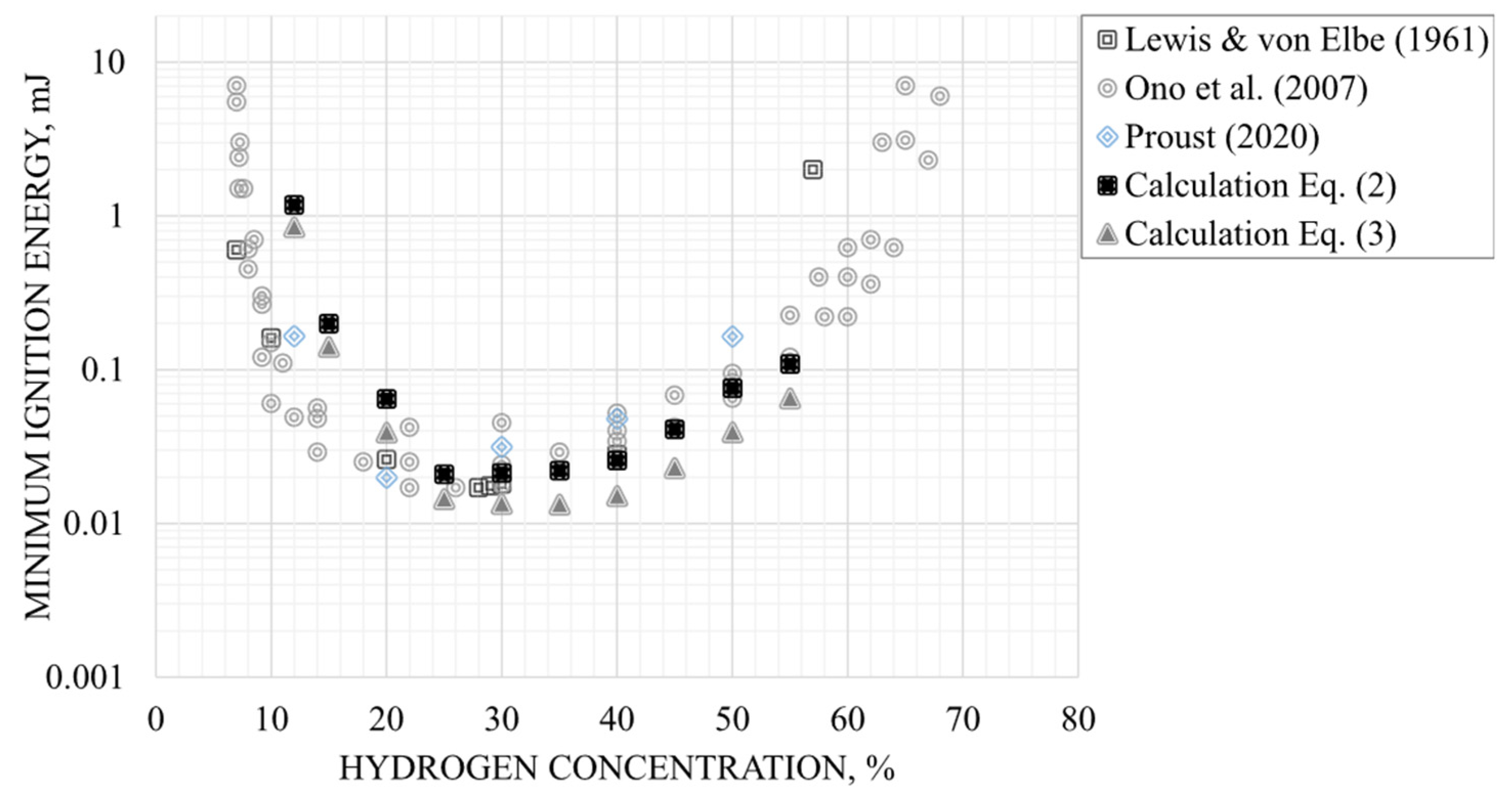
- Hydrogen ignites very easily when it is close to stoichiometric conditions where a minimum ignition energy (MIE) in air is observed at only 17 µJ [21] (Figure 2) – for comparison, an electrostatic discharge just felt by a person is around 1000 µJ – and the MIE even decreases in pure oxygen to 1.2 µJ [22]. This characteristic is reflected by the gas sub-group IIC for equipment used in potentially explosive atmospheres (ATEX) according to the EU legislation Directive 2014/34/EU [23];
- The burning velocity of hydrogen in air at stoichiometric ambient conditions is 2.37 m/s [24] and can even increase up to 3.5 m/s at a concentration of 40.1% [25]. Related to its fast chemical kinetics and high diffusivity, this burning velocity is higher than that of other hydrocarbon fuel – air mixtures and results in a greater chance for a transition of the combustion mode from deflagration to detonation;
- Due to its small-sized molecule, hydrogen leaks are more likely to occur than with other inflammable gases. Furthermore, due to its low viscosity, the volume flow rate is then nearly 3 times higher compared for instance with methane [26];
- At ambient conditions, hydrogen is about 8 times lighter than natural gas and 14 times lighter than air. While released in an open environment, it will typically rise and disperse rapidly. This is a safety advantage in an outside environment for instance with a subsonic or vertically orientated leak, but it has to be carefully taken into account in a confined space by a pertinent leak detection system and a ventilation assuring sufficient air dilution at the leak source;
Figure 1.
Influence of temperature on the lower (LFL) and upper (UFL) flammability limits for hydrogen and methane, respectively [27].
Figure 1.
Influence of temperature on the lower (LFL) and upper (UFL) flammability limits for hydrogen and methane, respectively [27].
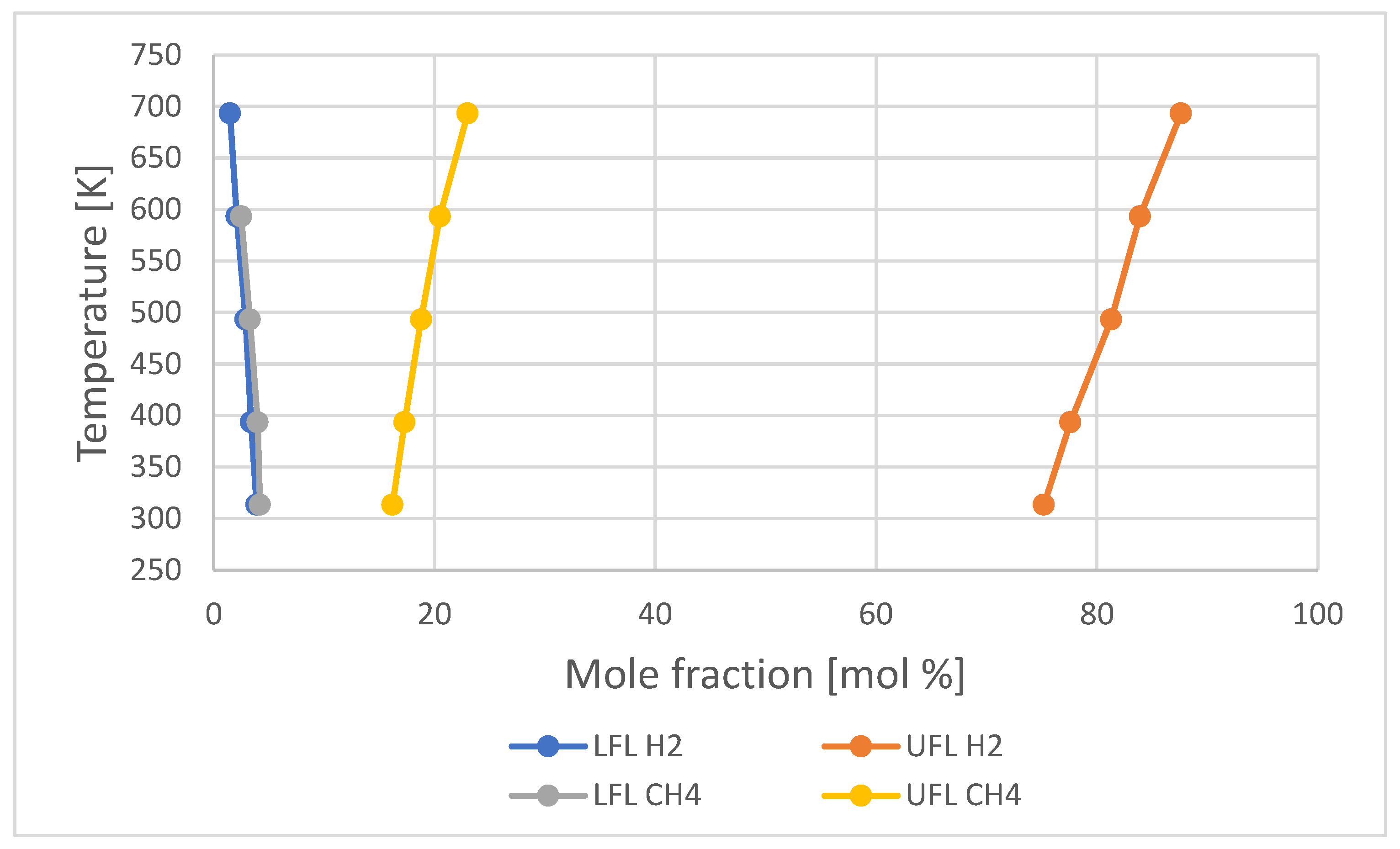
Figure 2.
MIE calculated and experimental as a function of hydrogen concentration in air [28].
Figure 2.
MIE calculated and experimental as a function of hydrogen concentration in air [28].
- A jet fire of hydrogen generates a pale blue flame almost invisible in daylight (Figure 3a). However, its visibility can be increased if particles are entrained in the flame (e.g. dust) and hydrogen flames are also visible at night, as shown in Figure 3b. In air, a premixed stoichiometric blend can lead to a flame temperature of 2403 K [24];
- The dominant energy emission occurs in the mid-infrared, where the peak irradiance is more than 1000 times greater than the peak measured in the ultraviolet. Thermal radiation is therefore very limited and unconventional UV detection is required [29];
- According to different experiences with hydrogen at concentrations below 10% vol. in air [30], the explosion resembles to a flash fire with nearly no pressure rise. At higher concentrations, deflagration is observed where the flame speed is subsonic, and the maximum pressure peak is reached at 8 bar in air and 10 bar in pure oxygen [31]. At supersonic flame speeds, detonation occurs and can be observed at ranges in excess of 12,5% vol. of hydrogen where explosion pressures 15 to 20 times greater than the initial pressure can occur at the detonation front depending on concentration and turbulence conditions in the environment. The most violent reaction occurs when hydrogen is near to its stoichiometric value of 29,5% vol. in air. Table 1 summarises the main differences between deflagration and detonation;
- Various embrittlement mechanisms such as hydrogen-induced cracking or blistering are also possible with hydrogen depending both on the metal, alloy or composite selection and on the process parameters (temperature and pressure typically), so that the choice of the material constitutes a point of vigilance when designing containers or pipelines (Section 3).
Because of the complex process of establishing regulations, they often lag behind innovation. However, the normative framework governing hydrogen safety has benefitted from dynamic updates in recent years. These updates have been driven by committees such as ISO Technical Committee 197, which focuses on standardisation in the field of systems and devices for the production, storage, transport, measurement, and use of hydrogen. In Europe, CEN/TC 268 Working Group 5 deals specifically with hydrogen technology applications in support of Directive 2014/94/EU and its planned revision under the ‘Fit for 55’ package, as requested by the European Commission. In addition, CEN-CENELEC Joint Technical Committee 6 is responsible for devices and connections related to the production, storage, transport, distribution, measurement, and use of hydrogen from renewable and other energy sources.
2.2. Lessons Learnt with Hydrogen
To address correctly the risks, the specific characteristics of hydrogen shall be taken into account in risk analyses. A prudent step before any risk analysis actually is to look at potential lessons learnt from hydrogen regarding the process previously implemented during its lifecycle. There are only two hydrogen-specific free databases in the world:
Additionally, there are some non-specific free databases such as the French database Accident Reporting Information Analysis (ARIA) [35] maintained by the Bureau for Analysis of Industrial Risks and Pollutions (BARPI) which reports 955 incidents with hydrogen therein mainly involved as a chemical product actually and not as an energy carrier, or the Japanese one, the High Pressure Gas Safety Act Database [36] which presents a compilation of statistics on accidents, with a focus on accidents resulting in injury or death, especially those having occurred at manufacturing plants for high pressure gas. Some further databases are described by Campari et al. [37].
The HIAD 2.0 analysis of Wen et al. [38] states that ‘about half of the incidents were related to [organisational] and management factors. Material/manufacturing errors are the second main cause with a share of 35%. Other main factors include individual and human factors (29%), system design errors (27%) and job factors (14%). Only 11% of the incidents were related to installation errors. An important message from this analysis is that the “soft factors” play just as big a role in the causes of incidents as technical factors’ (Figure 4).
A similar conclusion has been drawn by BARPI for incidents involving hydrogen in the chemical, petrochemical, refining, and nuclear industries, as well as in transport (Table 2). Indeed, an analysis shows that in over 70% of the cases, the organisational and human factor played a predominant role in the root causes for these accidents to occur. BARPI therefore stressed that constant vigilance must be exercised at all levels - management, field operatives, subcontractors - bearing in mind that in the presence of hydrogen, the risk of ignition is permanent [39]. It can be noted that, owing to the typology of the accidents and to the fast kinetics of the associated phenomena, the human consequences of these accidents mainly concern the employees of the damaged sites, the first responders and the public being rarely affected. For example, whenever the status of the victim·s was provided, the fatal outcomes turned out to concern employees (the five cases recorded for France were all linked to maintenance work).
3. Gaseous Transport and Buffer Storage
The materials for the transport of gaseous hydrogen are subject to numerous studies. By limiting the pipe wall thickness required to withstand high pressure, high-strength steels can prove economically relevant for safely transporting large hydrogen gas quantities over a long distance in pipelines although this gas raises specific constraints [13]:
- In many circumstances, hydrogen gas can weaken metallic materials, notably high-strength steels containing ferritic phases;
- The volumetric density of hydrogen gas being much lower than that of natural gas, the pressure has to be increased in order to deliver the same amount of energy whereas, thanks to the higher compressibility factor of hydrogen, its pressure drop in a pipeline over a long distance is significantly lower than that of natural gas.
The renewable-energy-related buffer storage of hydrogen shall also be considered because it induces more severe constraints than its transport in terms of cycling. This buffer storage allows the conversion of excess electricity into hydrogen to compensate for the intermittency inherent to both photovoltaic panels and windfarms as the stored gas can be reinjected at the appropriate times either into the electricity network (after reconversion) or into the gas one (by methanation) or, of course, be directly used as a clean fuel (green hydrogen).
Addressing those concerns has led to assessing the case of the high-strength X80 steel. This has been engaged in a collaborative way with ENGIE and CEA-LITEN [40,41]. The test bench herein presented entered that collaborative way and has been designed for carrying out tests on defect-bearing pipe sections under hydrogen that should help quantifying the impact of hydrogen on failure pressure and lifespan. Two subsequent phases have been followed:
- Validation phase: the main objective was to demonstrate the capacity of the implemented bench to test a selection of representative pipe sections under cyclic loading at a low frequency (40 s per cycle typically). The possibility to test under monotonic loading was also to be demonstrated.
- Operational phase: a series of bursting tests under monotonic loading has been implemented on pre-notched pipe sections. The pressurised medium was pure hydrogen, which corresponds to a ‘worst-case’ scenario, for the effect to be as more significant as possible. In each case, a reference test has been carried out under nitrogen pressure for comparison with the results obtained under hydrogen. SEM observations initially aimed to determine the fragile or brittle nature of the fractures.
Those two phases are detailed below.
3.1. Validation Phase
The test bench co-owned by CNRS and ENGIE has been implemented for several purposes, the first two ones being of prime interest for safety considerations:
- To validate defect failure assessment models by comparing their numerical results with the experimental ones obtained on the test bench;
- To study the stability or instability of internal as well as external defects on hydrogen pipelines, considering the fact that, in highly populated areas such as Western Europe, the most frequent incidents on natural-gas pipelines are due to mechanical damage in relation to third-party aggressions [42]. Internal corrosion-type defects are in the minority, or even nonexistent, due to the non-corrosive qualities of the transported gas, but there may be occurrences of internal defects at the girth welds (Figure 5c);
- To validate the transferability of the fracture-mechanics results obtained on laboratory specimens to a real structure;
- To possibly serve as an instrumented hydrogen reservoir to be coupled for instance with an electrolyser, as in the case of a renewable-energy-related buffer storage.
More particularly, the test bench has been designed and implemented for reproducing real operating conditions in terms of:
- presence of idealised or realistic defects identical to those identified by the industrial partner (Figure 5);
- same gas/defect interactions as for a distribution pipeline;
- bi-axial stress state in the pipeline section.
In comparison with usual laboratory tests, compliance with the above conditions was deemed to mean that the test bench would best reproduce the real operating conditions of a gas transport pipeline. It is in this regard that it has been implemented as a complementary means of investigation compared to those available at ENGIE and CEA-LITEN. Technical requirements included specifications for conducting monotonic bursting tests up to 300 bar or cyclic ones between 40 and 100 bar, in hydrogen or nitrogen, and the test cell (Figure 6) was itself designed for possibly testing 500 mm-long DN 900/NPS 36 (Ø 914.4 mm), DN 600/NPS 24 (Ø 609.6 mm), or DN 300/NPS 12 (Ø 323.9 mm) pipe sections. Coupled with the representative operating conditions mentioned above, these dimensions are large enough for the test bench to be considered at TRL 6 level in terms of technological readiness. The operating conditions are in accordance with the main diagram shown on Figure 7; a controllable valve has been added to integrate any refilling of the buffer cylinder into the pilot program, so that cycling is not interrupted even in the event of micro-leakage.
The purity required to evaluate any embrittlement effect (less than 1 ppm mol O₂ and less than 3 ppm mol H₂O) can be satisfied through the use of the commercial high-quality 'Alphagaz 2' hydrogen gas (Air Liquide) which contains less than 0.1 ppm mol O₂ and less than 0.5 ppm mol H₂O.
The description and the characteristics of the ATEX zones, as imposed by explosive-atmosphere-related safety rules, for the room hosting the test bench (the control computer is located outside this room) were established during the zoning; the internal volume of the protective bell (filled with nitrogen gas until the pipe section bursts) and its upper vent fall within Zone 1, while its external volume inside the mobile hood equipped with a continuously operating air-extraction duct (Figure 6b) falls within Zone 2. The possibility of performing tests with CH₄ – H₂ or N₂– H₂ mixtures would not derogate from these provisions. Filling volumes are placed between the pipe-section wall and the test-cell core in order to reduce the volume of hydrogen as much as possible (Figure 6a) for both safety and operating reasons, the free volume being only intended for the occasional installation of severely dented pipe sections (Figure 5a).
The most salient constraint regarding the test-bench specifications was to ensure a bi-axial stress state in the pipe section. The possibility of introducing axial stresses (up to 21.5 MPa typically for 100 bar applied in a DN 300 pipe) has nevertheless been validated by clamping both ends of thick-walled pipe sections, where ‘thick-walled pipe’ refers to a 7.7 mm wall thickness for a DN 300 pipe as compared to 4.2 mm for a ‘thin-walled pipe’; both pipe sections shall however be considered as ‘thin-walled’ cylinders in terms of high-pressure containment (ratio between the outer and inner diameters below 1.1). The introduction of axial stresses aims at replicating real operating conditions, namely no axial stresses (the length of the pipe section can decrease freely as a result of the increase in internal pressure) or constrained axial deformations (clamped pipe section) for replicating above-ground and underground pipelines, respectively.
3.2. Experimental Phase
For low-strength steels, prevailing contentions [43] posit that embrittlement under static load would be the result of the synergetic action of shear localisation and decohesion mechanisms, but could be intergranular under cyclic load. Fractographic evidence indeed suggests that hydrogen-assisted transgranular fracture under static loading is induced by void or microcrack initiation through decohesion at internal interface (precipitate/inclusion or phase boundaries) ahead of a crack/notch accompanied by shear localisation leading to the linking of the void/microcrack with the tip of the crack.
For high-strength steels such as X80, modelling consists in taking into account its ferritic-pearlitic microstructure. A thorough study dealing with the hydrogen embrittlement susceptibility of the X80 steel had previously been performed [45] and the respective involvement of different hydrogen populations (adsorbed, diffusible, or trapped) on the associated embrittlement mechanisms had been addressed through tensile testing at various strain rates and hydrogen pressures. Changes of gas (hydrogen or nitrogen) during loading had also been imposed in order to be able to discriminate amongst the potential hydrogen embrittlement mechanisms proposed in the literature. The results of these tests have shown that hydrogen induces several kinds of damage including decohesion along ferrite/pearlite interfaces and microcrack initiations on the external surface.
Several other studies had been performed ; one of them (Figure 8) showed a dramatic effect of hydrogen on elongation for two different strain rates, as compared to tests in air and in nitrogen gas at the same gas pressure of 300 bar [44].
Defects in microstructure, particularly precipitates, as well as dislocations are known to act as trap sites for hydrogen but the hydrogen effect on mechanical properties may also be reinforced in the presence of highly triaxial stress states. It had therefore been decided to test unclamped DN 300 pipe sections with a notch sized for an anticipated failure at 67 ± 15 bar under monotonic loading with a ramp of 0.1 bar.s-1. The external notch was machined at equal distance from both ends and was oriented in the longitudinal direction of the pipe section. Pre-notched pipe sections were also equipped in their external part with several type CEA-06-125UT-350 'rosettes' (Vishay Micromesures), each with two strain gauges set at 90°. Conditions for the proper diffusion of hydrogen before testing were also specified ; they set the minimum exposure time to 12 h under slight overpressure. All tests were succesfully performed and resulted in ruptures with full opening of the pipe section (Figure 9).
Fractographic investigations usually focus on the characterisation of the either ductile or brittle mode of rupture; both modes were however observed on every tested pipe section. This dual behaviour is relevant with the strong texture that exists in the API 5L X80 steel where the orientation of the ferritic-pearlitic microstructure is reinforced by rolling at the elaboration stage.
4. Safe Mass Storage in the Solid State
Between production and uses of hydrogen, one of the main bottlenecks in its clean-energy-based chain is related to its distribution and consequently to the mass storage of this light element. Concerns to be addressed include:
- Physical or chemical operations as simple as possible for long-time operations;
- Kinetics fast enough to anticipate production and delivery that are both mostly intermittent;
- Safe modes of management.
In terms of densification, comparison between hydrogen in molecular form H₂ either as liquid at 20.4 K or as gas under a pressure of 700 bar and a solid atomic form such as MgH₂ leads to figures of merit of 71, 42, and 106 kg/m3, respectively. Solid-state storage also eliminates the safety problems associated with gaseous hydrogen. Incidentally, many other solid forms are actively considered with wide panels of specific performances within reach: e.g. d-metal-based metals and alloys, complex metal hydrides (alanates and boranates), nano-carbonaceous adsorbers, molecular organic frameworks, and liquid organic hydrogen carriers. As shown in Figure 10, during the past 20 years, there was a huge increase of published reviews dealing with hydrogen storage, about 40% of them being, however, specifically devoted to magnesium-based systems.
Compared to the many metals and alloys able to absorb hydrogen reversibly, magnesium exhibits very interesting advantages as well as some drawbacks. It is the seventh more abundant element in the Earth’s crust and its extractive and refinement metallurgies are well developed. Consequently, it is not so expensive compared to aluminum. Also, recycling Mg by-products is rather easy since it is a bio-compatible element. It forms a mono-element hydride MgH₂ that will not be subject to disproportionation during adsorption/desorption cycles. Furthermore, the maximum hydrogen uptake is amongst the best for a solid-state metal hydrogen carrier, namely 7.6 wt%.
However, two main drawbacks have appeared when handling the reaction Mg ↔ MgH₂:
- The reaction is particularly slow, even when starting from raw powdered samples;
- Active reaction takes place at over 300 °C but, interestingly, under a few bars of hydrogen pressure.
Considering the first point, the kinetics can be promptly accelerated by mechanical treatment of the metal particles. Since Mg is a ductile metal, the well-known method to promote a reactive material is to use the high-energy ball-milling technology, which can be applied to the pre-hydrogenated particles exhibiting the same fragile character as ceramics. The ball-milling treatment leads to reduce the size of the particles, which themselves contain nano-sized crystallites, to a few micrometres. Thanks to this mechanical treatment, the specific surface for hydrogenation reaction is considerably increased and many defects (such as nucleation centres to form MgH₂) are distributed in the structure. Moreover, additives of many types, such as metal, alloys, oxides, halides, or alanates, which work as catalysts when introduced during the ball-milling operation, are proving to be markedly efficient in terms of hydrogenation/dehydrogenation kinetics. However, the ball-milling method is of limited value for the purpose of mass production, due also to energy, manpower and safety (highly pyrophoric) concerns.
Alternative routes have been found by using severe plastic deformation (SPD) techniques [47] enabling to develop in bulk Mg-based materials the conditions required for a rapid nucleation. SPD techniques indeed result in multiplying the crystal defects such as dislocations and twins, densifying the grain boundary network, and eventually delivering an ultrafine-grained structure. The main in-lab techniques used for demonstration are high-pressure torsion [48,49], equal-channel angular pressing [50,51], multiple cold rolling, accumulative roll bonding [52,53] and fast forging [55,56]. Once again, energy efficiency will be the key to effective implementation on a very large scale.
The second main drawback mentioned above proves critical for the low-temperature metal hydrides based on d-transition metals since they can reversibly store around 2 wt% H₂ at moderate temperature and mostly work under a maximum hydrogen pressure of a few tens of bars. The enthalpy of reaction of H₂ with Mg to form MgH₂, ΔH ~ - 74 kJ/molH₂, leads to exothermic absorption and endothermic desorption. It corresponds to a third of the heat of combustion of hydrogen, which is ~ 33 kWh/kgH₂. This means that the thermal part of the energy must be managed and better integrated throughout the process, using appropriate materials and tanks. In this respect, the combined use of Expanded Natural Graphite (ENG) mixed with MgH₂-based compacts and of an ancillary tank containing a Phase-Change Material (PCM) allows to increase the total storage performance up to an 80% energy efficiency [56,57,58,59].
To obtain such results, the level of doping with ENG has, on the one hand, to markedly improve the conductivity of the MgH₂-based compacts and, on the other hand, the melting temperature of the PCM must be adjusted between the absorption and desorption temperatures of the compacts, as shown in Figure 11. In such a configuration, ideal absorption can be achieved at 10 bar with a temperature maintained down to 350 °C, while desorption achieved at almost 310 °C leads to delivering a pressure of about 2 bar.
Interestingly, autonomous mass storage units can be optimised with the heat of the absorption transferred for melting the PCM and then automatically re-used when solidifying the PCM to desorb the MgH₂ compacts [19,60].
The MgH₂ compacts have been tested up to ~ 7500 adsorption/desorption cycles without significant loss of either the maximum H-uptake or of the kinetics of the reactions. By doing so, elementary tanks (~100 kgMgH₂:~15 kgH₂) can be assembled into large containers to eventually form storage units ranging from one hundred kilowatts to tens of megawatts.
Alongside these performances and capacities, research and development activities should pay attention to the potential permeation of hydrogen with regard to all the shells and other items of equipment involved in this technology, for their safest use. Also, the different walls, pipes and the ancillary equipment of the tanks having to withstand hydrogen gas pressure, mechanical efforts, and temperature variations, either separately or concomitantly, need to be analysed in terms of potential hydrogen embrittlement [61].
Industries that need large quantities of hydrogen, such as the steel, cement, chemical, or glass industries, as well as large refuelling stations, will eventually be able to use large solid-state hydrogen storage units operating on site and supplied with green hydrogen (renewably-sourced) in complete safety (pressure < 15 bar) [4].
Author Contributions
Conceptualisation, P.L.; methodology, P.L. and F.L.; validation, F.L., B.W., P.L. and D.F.; writing—original draft preparation, B.W., D.F. and P.L.; writing—review and editing, P.L., B.W., D.F. and F.L.; supervision, F.L. All authors have read and agreed to the published version of the manuscript.
Funding
The implementation of the test bench described in Section 3 was funded by the French research-funding Agence Nationale de la Recherche through grants number ANR-05-PANH-006 and ANR-09-HPAC-003.
Acknowledgments
P.L. and F.L. would like to thank their former partners Rémi Batisse and Stéphane Hertz-Clémens at ENGIE for their long-lasting collaboration. Although anticipated by the coming of Shin Ueda and Yuki T. Williams to Villetaneuse, the planned collaborative study of burst pipe sections using the FRASTA fractographic technique at Ritsumeikan University did not materialise following the passing away of Professor Akira Ueno, to whom this paper is dedicated.
Conflicts of Interest
The authors declare no conflict of interest.
References
- Zhang, L.; Jia, C.; Bai, F.; Wang, W.; An, S.; Zhao, K.; Li, Z.; Li, J.; Sun, H. A comprehensive review of the promising clean energy carrier: Hydrogen production, transportation, storage, and utilization (HPTSU) technologies. Fuel 2024, 355, 129455. [Google Scholar] [CrossRef]
- Pique, S.; Weinberger, B.; de Dianous, V.; Debray, B. Comparative study of regulations, codes and standards and practices on hydrogen fuelling stations. Int. J. Hydrogen Energ. 2017, 42, 7429–7439. [Google Scholar] [CrossRef]
- Darkrim Lamari, F.; Weinberger, B.; Girodon-Boulandet, N.; Fagnon, N.; Batisse, R.; Briottet, L.; Langlois, P. High-pressure hydrogen storage for on-board applications and for coupling renewable energies to the electric grid. High Pressure Res. 2009, 29, 660–664. [Google Scholar] [CrossRef]
- Fruchart, D.; Jehan, M.; Skryabina, N.; de Rango, P. Hydrogen Solid State Storage on MgH2 Compacts for Mass Apllications. Metals 2023, 13, 992. [Google Scholar] [CrossRef]
- Guo, L.; Su, J.; Wang, Z.; Shi, J.; Guan, X.; Cao, W.; Ou, Z. Hydrogen safety: An obstacle that must be overcome on the road towards future hydrogen economy. Int. J. Hydrogen Energ. 2024, 51, 1055–1078. [Google Scholar] [CrossRef]
- Calabrese, M.; Portarapillo, M.; Di Nardo, A.; Venezia, V.; Turco, M.; Luciani, G.; Di Benedetto, A. Hydrogen Safety Challenges: A Comprehensive Review on Production, Storage, Transport, Utilization, and CFD-Based Consequence and Risk Assessment. Energies 2024, 17, 1350. [Google Scholar] [CrossRef]
- Kazemi, M.; Brennan, S.; Molkov, V. Hydrogen Safety by Design: Exclusion of Flame Blow-Out from a TPRD. Hydrogen 2024, 5, 280–292. [Google Scholar] [CrossRef]
- Di Lullo, G.; Oni, A.O.; Kumar, A. Blending blue hydrogen with natural gas for direct consumption: Examining the effect of hydrogen concentration on transportation and well-to-combustion greenhouse gas emissions. Int. J. Hydrogen Energ. 2021, 46, 19202–19216. [Google Scholar] [CrossRef]
- Di Lullo, G.; Giwa, T.; Okunlola, A.; Davis, M.; Mehedi, T.; Oni, A.O.; Kumar, A. Large-scale long-distance land-based hydrogen transportation systems: A comparative techno-economic and greenhouse gas emission assessment. Int. J. Hydrogen Energ. 2022, 47, 35293–35319. [Google Scholar] [CrossRef]
- Yang, M.; Hunger, R.; Berrettoni, S.; Sprecher, B.; Wang, B. A review of hydrogen storage and transport technologies. Clean Energy 2023, 7, 190–216. [Google Scholar] [CrossRef]
- Makaryan, I.A.; Sedov, I.V.; Salgansky, E.A.; Arutyunov, A.V.; Arutyunov, V.S. A Comprehensive Review on the Prospects of Using Hydrogen–Methane Blends: Challenges and Opportunities. Energies 2022, 15, 2265. [Google Scholar] [CrossRef]
- Tsiklios, C.; Hermesmann, M.; Müller, T.E. Hydrogen transport in large-scale transmission pipeline networks: Thermodynamic and environmental assessment of repurposed and new pipeline configurations. Appl. Energy 2022, 327, 120097. [Google Scholar] [CrossRef]
- Briottet, L.; Batisse, R.; de Dinechin, G.; Langlois, P.; Thiers, L. Recommendations on X80 steel for the design of hydrogen gas transmission pipelines. Int. J. Hydrogen Energ. 2012, 37, 9423–9430. [Google Scholar] [CrossRef]
- Sakintuna, B.; Lamari, F.; Hirscher, M. Metal hydride materials for solid hydrogen storage. Int. J. Hydrogen Energ. 2007, 32, 1121–1140. [Google Scholar] [CrossRef]
- Cao, Z.; Habermann, F.; Burkmann, K.; Felderhoff, M.; Mertens, F. Unstable Metal Hydrides for Possible On-Board Hydrogen Storage. Hydrogen 2024, 5, 241–279. [Google Scholar] [CrossRef]
- Lázár, M.; Mihálik, I.; Brestovič, T.; Jasminská, N.; Tóth, L.; Dobáková, R.; Duda, F.; Kmet’ová, L.; Hudák, Š. A Newly Proposed Method for Hydrogen Storage in a Metal Hydride Storage Tank Intended for Maritime and Inland Shipping. J. Mar. Sci. Eng. 2023, 11, 1643. [Google Scholar] [CrossRef]
- Li, Z.-Y.; Sun, Y.-J.; Zhang, C.-C.; Wei, S.; Zhao, L.; Zeng, J.-L.; Cao, Z.; Zou, Y.-J.; Chu, H.-L.; Xu, F.; et al. Optimizing hydrogen ad/desorption of Mg-based hydrides for energy-storage applications. J. Mater. Sci. Technol. 2023, 141, 221–235. [Google Scholar] [CrossRef]
- Skryabina, N.; Aptukov, V.; Fruchart, D. Role of induced elastic deformations at the Mg/MgH2 transformation. J. Alloy. Metall. Systems 2024, 5, 100064. [Google Scholar] [CrossRef]
- Jehan, M.; Fruchart, D. McPhy-Energy's proposal for solid state hydrogen storage materials and systems. J. Alloys Compd. 2013, 580, 343–348. [Google Scholar] [CrossRef]
- Regulation (EC) No 1272/2008 of the European Parliament and of the Council of 16 December 2008 on classification, labelling and packaging of substances and mixtures, amending and repealing Directives 67/548/EEC and 1999/45/EC, and amending Regulation (EC) No 1907/2006. Available online: http://data.europa.eu/eli/reg/2008/1272/2023-12-01 (also at web.archive.org).
- Schroeder, V.; Holtappels, K. Explosion Characteristics of Hydrogen-Air and Hydrogen-Oxygen Mixtures at Elevated Pressures. In Proceedings of the 1st International Conference on Hydrogen Safety, Pisa, IT, 8-10 September 2005. Available online: http://conference.ing.unipi.it/ichs2005/Papers/120001.pdf (also at web.archive.org). [Google Scholar]
- Lewis, B.; von Elbe, G. Combustion, flames and explosions of gases, 2nd ed.; Academic Press: New York and London, 1961. [Google Scholar] [CrossRef]
- Kuchta, J.M. Investigation of fire and explosion accidents in the chemical, mining, and fuel-related industries. Bull., U.S. Dept. Inter. Bur. Mines 1985, 680, 1–66. [Google Scholar]
- Cirrone, D.; Makarov, D.; Proust, C.; Molkov, V. Minimum ignition energy of hydrogen-air mixtures at ambient and cryogenic temperatures. Int. J. Hydrogen Energ. 2023, 48, 16530–16544. [Google Scholar] [CrossRef]
- Directive 2014/34/EU of the European Parliament and of the Council of 26 February 2014 on the harmonisation of the laws of the Member States relating to equipment and protective systems intended for use in potentially explosive atmospheres. Available online: https://eur-lex.europa.eu/eli/dir/2014/34/oj (also at web.archive.org).
- Verfondern, K. Hydrogen fundamentals. In Hydrogen Safety for Energy Applications: Engineering Design, Risk Assessment, and Codes and Standards, 1st ed.; Kotchourko, A., Jordan, Th., Eds.; Butterworth-Heinemann, 2022; pp. 1–23. [CrossRef]
- Kroener, M.; Fritz, J.; Sattelmayer, T. Flashback limits for combustion-induced vortex breakdown in a swirl burner. J. Eng. Gas Turbines Power 2003, 125, 693–700. [Google Scholar] [CrossRef]
- Hormaza Mejia, A.; Brouwer, J.; Mac Kinnon, M. Hydrogen leaks at the same rate as natural gas in typical low-pressure gas infrastructure. Int. J. Hydrogen Energ. 2020, 45, 8810–8826. [Google Scholar] [CrossRef]
- Hydrogen vehicle burn test, Vienne Fire and Rescue Service (France). Available online: https://www.youtube.com/embed/ow47SePNz-s (accessed on 22 March 2024).
- Schefer, R.W.; Kulatilaka, W.D.; Patterson, B.D.; Settersten, T.B. Visible emission of hydrogen flames. Combust. Flame 2009, 156, 1234–1241. [Google Scholar] [CrossRef]
- Proust, C. Fire and Explosion Safety in Hydrogen Containing Processes: State of the Art and Outstanding Questions. In Proceedings of the 9th International Seminar on Fire and Explosion Hazards, Saint Petersburg, RU, 21-26 April 2019; pp. 28–40. [Google Scholar] [CrossRef]
- Kuznetsov, M.; Grune, J. Experiments on flame acceleration and DDT for stoichiometric hydrogen/air mixtures in a thin layer geometry. In Proceedings of the 7th International Conference on Hydrogen Safety, Hamburg, DE, 11-13 September 2017. Available online: https://hysafe.info/uploads/papers/2017/199.pdf (also at web.archive.org). [Google Scholar]
- Hydrogen Incident and Accident Database. https://hysafe.info/hiad-2-0-free-access-to-the-renewed-hydrogen-incident-and-accident-database/ (also available at web.archive.org).
- Hydrogen Lessons Learned Reporting Tool. https://h2tools.org/lessons (also available at web.archive.org).
- French database ARIA ‘Analyse, Recherche et Information sur les Accidents’. https://www.aria.developpement-durable.gouv.fr/?lang=en (also available at web.archive.org).
- Reports of the High-Pressure Gas Safety Institute of Japan. https://www.khk.or.jp/english/ (also available at web.archive.org).
- Campari, A.; Nakhal Akel, A.J.; Ustolin, F.; Alvaro, A.; Ledda, A.; Agnello, P.; Moretto, P.; Patriarca, R.; Paltrinieri, N. Lessons learned from HIAD 2.0: Inspection and maintenance to avoid hydrogen-induced material failures. Comput. Chem. Eng. 2023, 173, 108199. [Google Scholar] [CrossRef]
- Wen, J.X.; Marono, M.; Moretto, P.; Reinecke, E.-A.; Sathiah, P.; Studer, E.; Vyazmina, E.; Melideo, D. Statistics, lessons learned and recommendations from analysis of HIAD 2.0 database. Int. J. Hydrogen Energ. 2022, 47, 17082–17096. [Google Scholar] [CrossRef]
- Accidentologie de l’hydrogène, Synthèse ARIA. 2009. Available online: https://www.aria.developpement-durable.gouv.fr/wp-content/files_mf/1373986645SYHydrogene2008.pdf (also at web.archive.org).
- Batisse, R.; Briottet, L.; de Dinechin, G.; Wastiaux, S.; Langlois, P. Ability of X80 steel for hydrogen gas transmission pipelines. In Proceedings of the 12th International Conference on Fracture; p. 3015.
- Briottet, L.; Moro, I.; Lemoine, P. Quantifying the hydrogen embrittlement of pipe steels for safety considerations. In Proceedings of the 3rd International Conference on Hydrogen Safety, Ajaccio, FR, 16-18 September 2009; Available online: https://conference.ing.unipi.it/ichs2011/papers/186.pdf (accessed on 22 May 2024).
- Bolt, R. A Guideline: Using or Creating Incident Databases for Natural Gas Transmission Pipelines. Report of IGU Study Group 3.4, 23rd World Gas Conference, Amsterdam, NL, 1-5 June 2006.
- Sofronis, P.; Robertson, I.M.; Johnson, D.D.; Somerday, B. Hydrogen Embrittlement-Fundamentals, Modeling, and Experiment. DOE Hydrogen Pipeline Working Group Meeting, Aiken, US-SC, 23-26 September, 2007.
- Batisse, R.; Cuni, A.; Wastiaux, S.; Briottet, L.; Lemoine, P.; de Dinechin, G.; Chagnot, C.; Castilan, F.; Klosek, V.; Langlois, P.; et al. Investigation of X80-steel grade for hydrogen gas transmission pipelines. In Proceedings of the 6th International Gas union Research Conference, Paris, FR, 8-10 October 2008. [Google Scholar]
- Moro, I.; Briottet, L.; Lemoine, P.; Andrieu, E.; Blanc, C.; Odemer, G. Hydrogen embrittlement susceptibility of a high strength steel X80. Mater. Sci. Eng. A 2010, 527, 7252–7260. [Google Scholar] [CrossRef]
- Pasquini, L.; Sakaki, K.; Akiba, E.; Alendorf, M.D.; Alvares, E.; Ares, J.R.; Babai, D.; Baricco, M.; Bellosta von Colbe, J.; Bereznitsky, M.; et al. Magnesium- and intermetallic alloys-based hydrides for energy storage: Modelling, synthesis and properties. Prog. Energy 2022, 4, 032007. [Google Scholar] [CrossRef]
- Edalati, K.; Akiba, E.; Botta, W.J.; Estrin, Y.; Ricardo, F.; Fruchart, D.; Grosdidier, T.; Horita, Z.; Huot, J.; Li, H.-W.; et al. Impact of Severe Plastic Deformation on Kinetics and Thermodynamics of Hydrogen Storage in Magnesium and Its Alloys. J. Mater. Sci. Technol. 2023, 146, 221–239. [Google Scholar] [CrossRef]
- Edalati, K.; Yamamoto, A.; Horita, Z.; Ishihara, T. High-pressure torsion of pure magnesium: Evolution of mechanical properties, microstructures and hydrogen storage capacity with equivalent strain. Scripta Mater. 2011, 64, 880–883. [Google Scholar] [CrossRef]
- Révész, Á.; Kánya, Z.; Verebélyi, T.; Szabó, P.J.; Zhilyaev, A.P.; Spassov, T. The effect of high-pressure torsion on the micro-structure and hydrogen absorption kinetics of ball-milled Mg70Ni30. J. Alloys Compd. 2010, 504, 83–88. [Google Scholar] [CrossRef]
- Skrypnyuk, V.M.; Rabkin, E.; Estrin, Y.; Lapovok, R. The effect of ball milling and equal channel angular pressing on the hydrogen absorption/desorption properties of Mg–4.95 wt% Zn–0.71 wt% Zr (ZK60) alloy. Acta Mater. 2004, 52, 405–414. [Google Scholar] [CrossRef]
- Skryabina, N.; Aptukov, V.; Romanov, P.; Fruchart, D.; de Rango, P.; Girard, G.; Grandini, C.; Sandim, H.; Huot, J.; Lang, J.; et al. Microstructure Optimization of Mg-Alloys by the ECAP Process Including Numerical Simulation, SPD Treatments, Characterization, and Hydrogen Sorption Properties. Molecules 2019, 24, 24010089. [Google Scholar] [CrossRef] [PubMed]
- Huot, J.; Tousignant, M. Effet of Cold Rolling on Metal Hydrides. Mater. Trans. 2019, 60, 1571–1576. [Google Scholar] [CrossRef]
- Floriano, R.; Leiva, D.R.; Melo, G.C.; Ishikawa, T.T.; Huot, J.; Kaufman, M.; Figueroa, S.J.A.; Mendoza-Zélis, L.A.; Damonte, L.C.; Botta, W.J. Low temperature rolling of AZ91 alloy for hydrogen storage. Int. J. Hydrogen Energ. 2017, 42, 29394–29405. [Google Scholar] [CrossRef]
- Skryabina, N.; Aptukov, V.; de Rango, P.; Fruchart, D. Effect of temperature on fast forging process of Mg-Ni samples for fast formation of Mg2Ni for hydrogen storage. Int. J. Hydrogen Energ. 2020, 45, 3008–3015. [Google Scholar] [CrossRef]
- de Rango, P.; Fruchart, D.; Aptukov, V.; Skryabina, N. Fast forging: A new SPD method to synthesize Mg-based alloys for hydrogen storage. Int. J. Hydrogen Energ. 2020, 45, 7912–7916. [Google Scholar] [CrossRef]
- Chaise, A.; de Rango, P.; Marty, P.; Fruchart, D.; Miraglia, S.; Olivès, R.; Garrier, S. Enhancement of hydrogen sorption in magnesium hydride using expanded natural graphite. Int. J. Hydrogen Energ. 2009, 34, 8589–8596. [Google Scholar] [CrossRef]
- Garrier, S.; Delhomme, B.; de Rango, P.; Marty, P.; Fruchart, D.; Miraglia, S. A new MgH2 tank concept using a phase-change material to store the heat of reaction. Int. J. Hydrogen Energ. 2013, 38, 9766–9771. [Google Scholar] [CrossRef]
- de Rango, P.; Marty, P.; Fruchart, D. Hydrogen storage systems based on magnesium hydride: From laboratory tests to fuel cell integration. Appl. Phys. A 2016, 122, 126–146. [Google Scholar] [CrossRef]
- Delhomme, B.; de Rango, P.; Marty, P.; Bacia, M.; Zawilski, B.; Raufast, C.; Miraglia, S.; Fruchart, D. Large scale magnesium hydride tank coupled with an external heat source. Int. J. Hydrogen Energ. 2012, 37, 9103–9111. [Google Scholar] [CrossRef]
- Garrier, S. Conception et simulation d'un réservoir à hydrure de magnésium avec récupération de la chaleur de réaction à l'aide d'un matériau à changement de phase. Ph.D. Thesis, Université de Grenoble, Grenoble, FR, 2011. https://theses.hal.science/tel-00940452/document. [Google Scholar]
- Djukic, M.B.; Bakic, G.M.; Zeravcic, V.S.; Rajicic, B.; Sedmak, A.; Wasim, M.; Perisic, J. Hydrogen embrittlement mechanisms in steels at different length scales. In Proceedings of the Communication at the 1st International Conference on Innovative Materials in Extreme Conditions, Belgrade, RS, 24–25 March 2022. [Google Scholar]
Figure 3.
Visibility of hydrogen flames: (a) Light-duty vehicle burn test [32]; (b) Space shuttle launch [29].
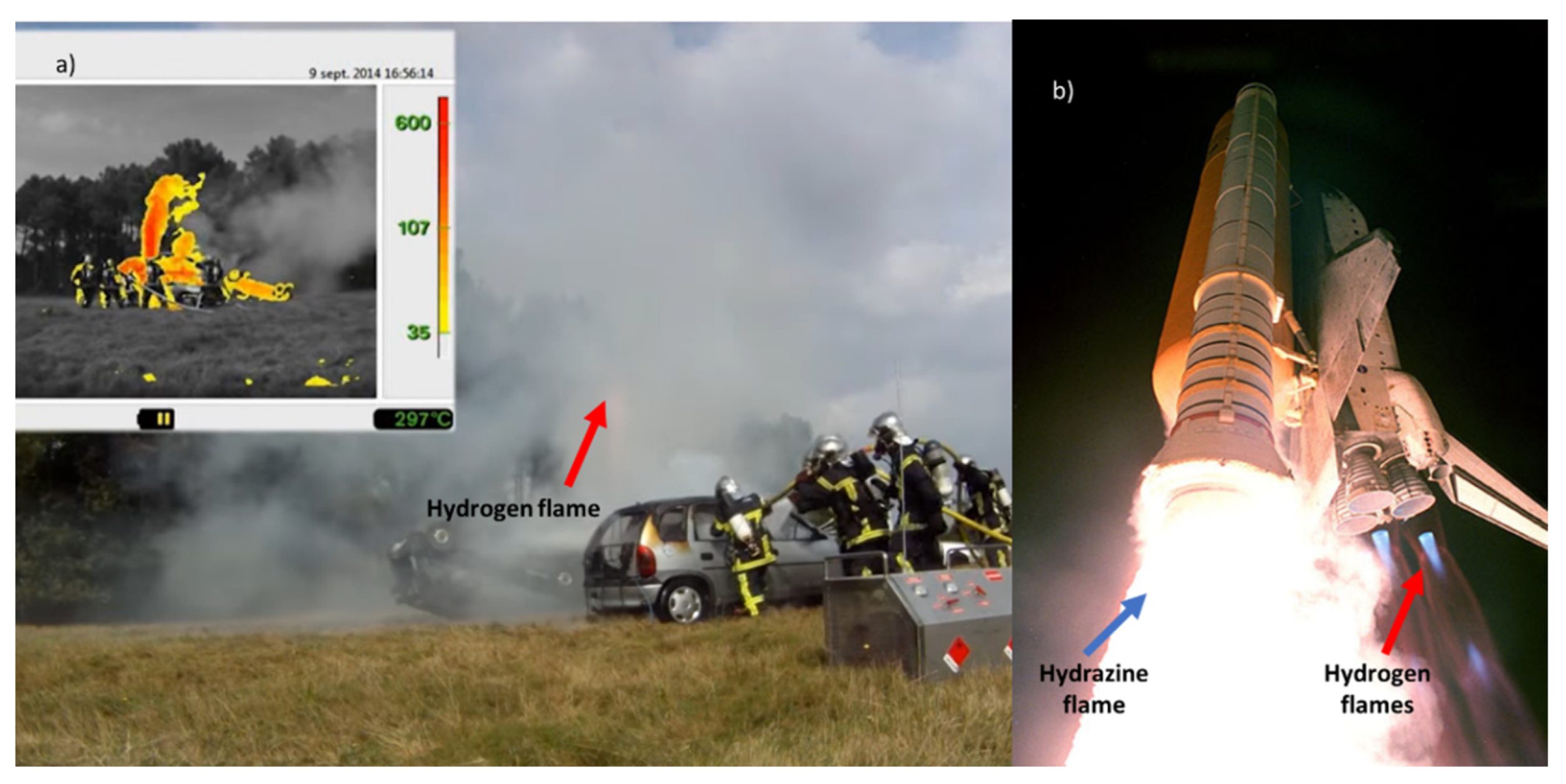
Figure 4.
Analysis of the HIAD database [38] in percentages of the events initiated by hydrogen or non-hydrogen systems (outer circle) and those related to different consequences (the inner circle).
Figure 4.
Analysis of the HIAD database [38] in percentages of the events initiated by hydrogen or non-hydrogen systems (outer circle) and those related to different consequences (the inner circle).
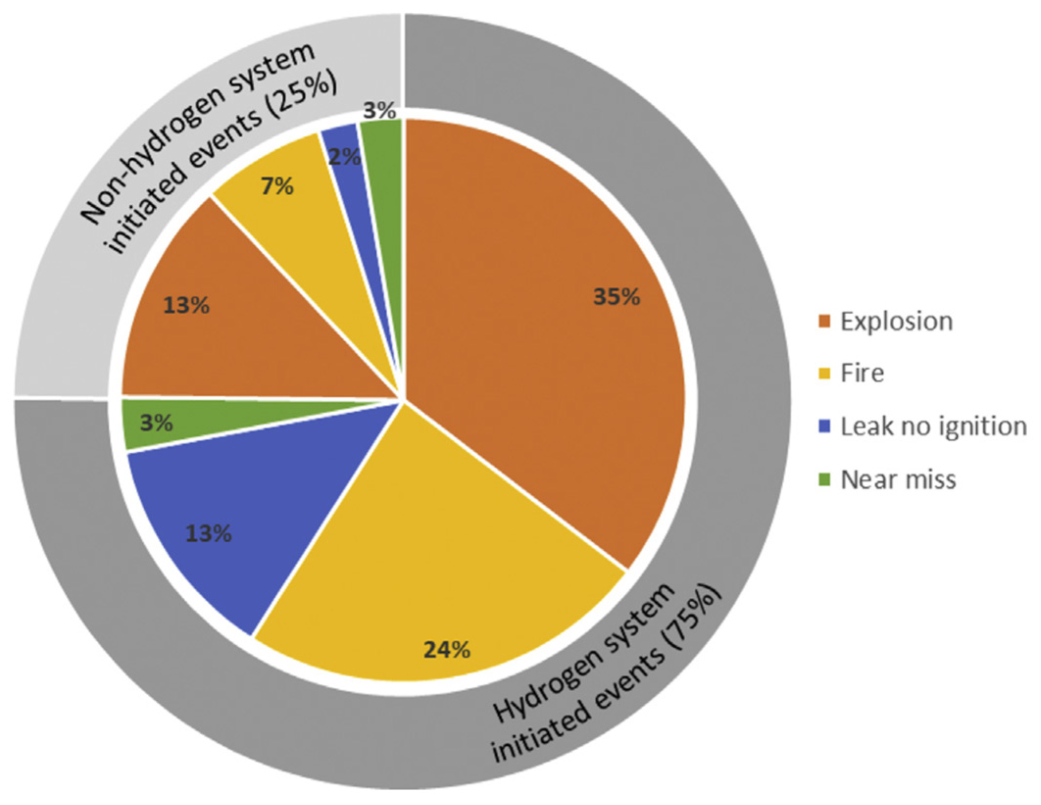
Figure 5.
Types of defects on pipelines: (a) Dents; (b) Gouges; (c) Welding defects; (d) Corrosion.
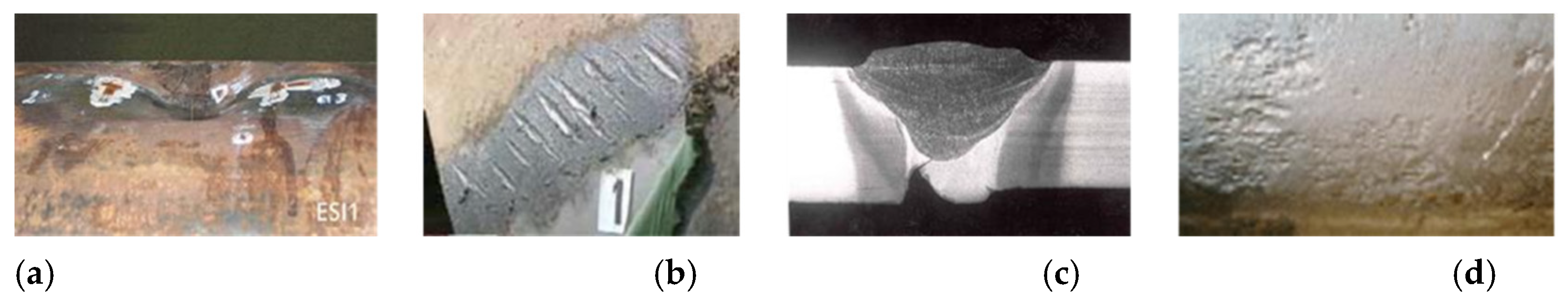
Figure 6.
(a) 3D cross-section of the test cell; (b) Mobile hood and air-extraction duct surrounding the test cell during hydrogen testing.
Figure 6.
(a) 3D cross-section of the test cell; (b) Mobile hood and air-extraction duct surrounding the test cell during hydrogen testing.
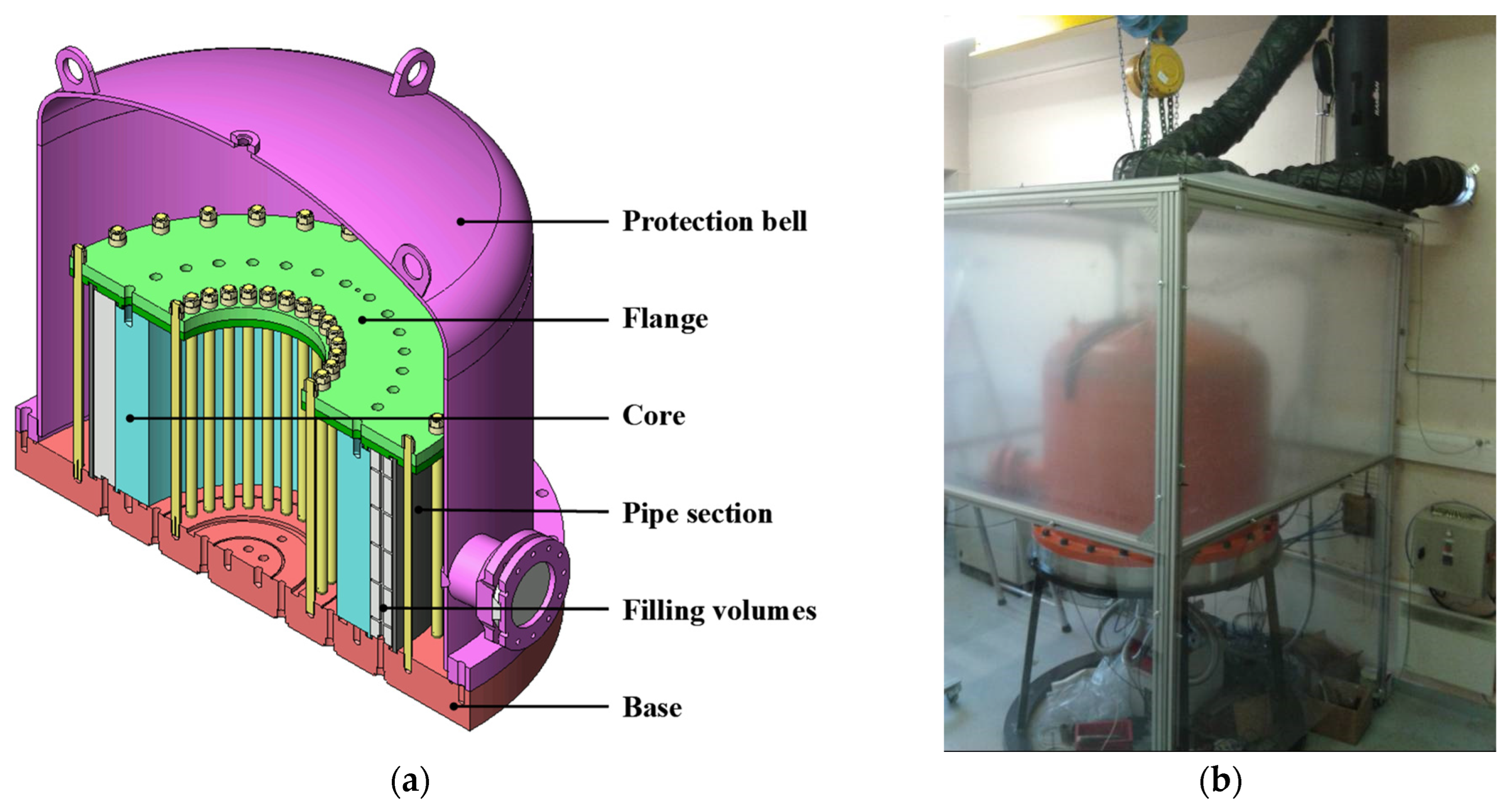
Figure 7.
Overall diagram of the test bench.

Figure 8.
Hydrogen impact on tensile properties as compared to air (blue curves) and nitrogen gas (green curves) [44].
Figure 8.
Hydrogen impact on tensile properties as compared to air (blue curves) and nitrogen gas (green curves) [44].
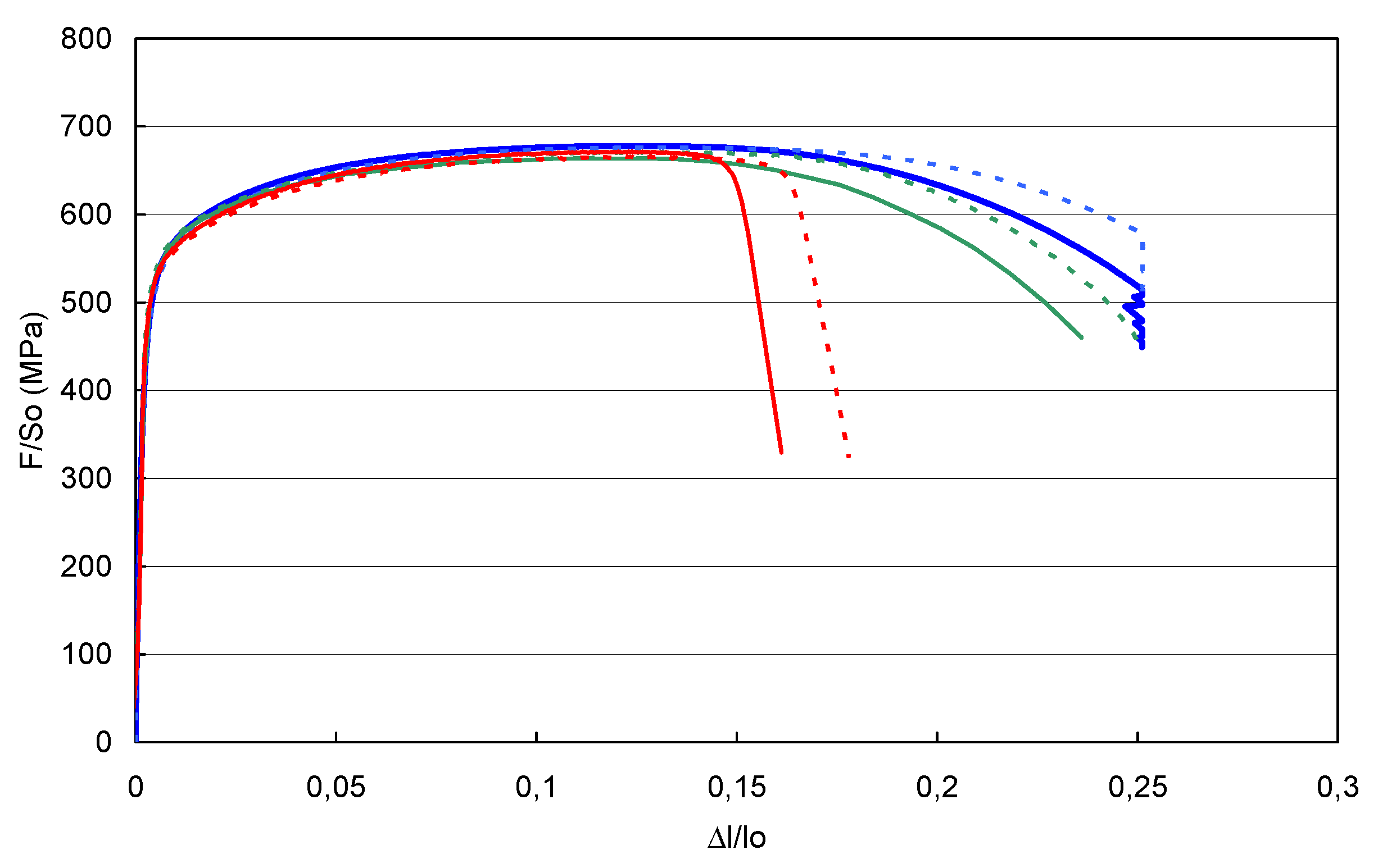
Figure 9.
Burst DN 300 pipe section still mounted on the test cell (a) and removed (b).

Figure 10.
Number of scientific reviews per year published along the 20 past years dealing with hydrides (black) or intermetallic systems (blue) and, more specifically, with magnesium-based hydrides only (red) (source Scopus) [46].
Figure 10.
Number of scientific reviews per year published along the 20 past years dealing with hydrides (black) or intermetallic systems (blue) and, more specifically, with magnesium-based hydrides only (red) (source Scopus) [46].

Figure 11.
Equilibrium diagram of the system Mg + H₂ ↔ MgH₂ showing for the PCM a melting temperature Tf ~340 °C intermediate between the absorption (Tabs) and desorption (Tdes) temperatures of the compacts.
Figure 11.
Equilibrium diagram of the system Mg + H₂ ↔ MgH₂ showing for the PCM a melting temperature Tf ~340 °C intermediate between the absorption (Tabs) and desorption (Tdes) temperatures of the compacts.
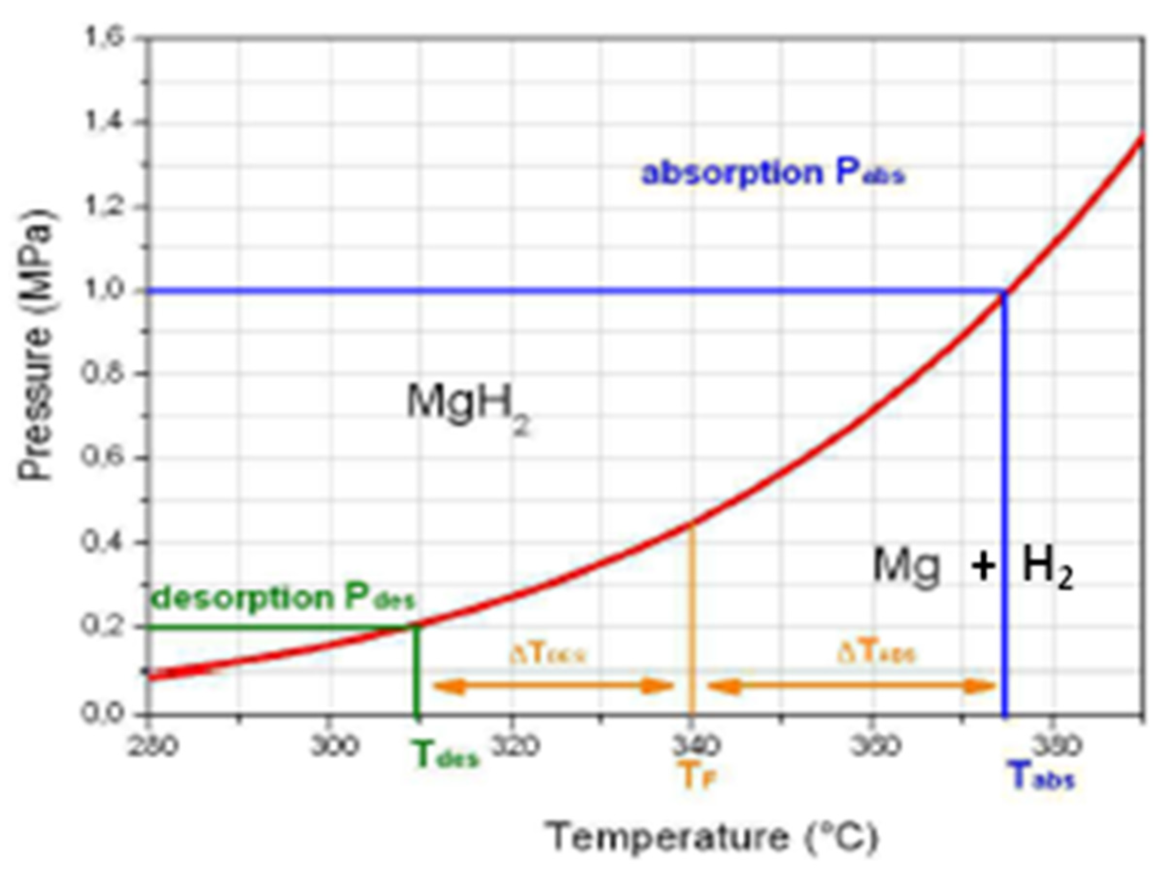

Table 1.
Main differences between deflagration and detonation.
| Deflagration | Detonation | |||
|---|---|---|---|---|
| Speed of flame propagation |
Subsonic, e.g. never exceeding the level of 10 m/s for lean hydrogen-air mixtures in a smooth 10 mm-thick channel |
Supersonic, e.g. for stoichiometric hydrogen – air mixtures: 1,600 to 2,000 m/s |
||
| Mechanism of propagation |
The flame front propagates by transferring heat and mass to the unburnt hydrogen–air mixture ahead of the front |
Powerful pressure wave compressing the unburnt gas ahead of the wave up to a temperature above the auto-ignition temperature |
||
| Protection by venting | Effective explosion protection | Ineffective protection |
Table 2.
Severity of the accidents (consequences and frequency) [39].
Table 2.
Severity of the accidents (consequences and frequency) [39].
| Consequence | Number of accidents* | % |
|---|---|---|
| Fatal outcome·s | 25 | 12 |
| Serious injuries | 28 | 13 |
| Injuries (serious ones included) | 70 | 33 |
| Onsite damage | 183 | 86 |
| Offsite damage | 17 | 8 |
| Operating losses | 89 | 42 |
| Population evacuation | 8 | 3.8 |
| * Out of 213 accidents where consequences are known, as collected until 2010 by BARPI. | ||
Disclaimer/Publisher’s Note: The statements, opinions and data contained in all publications are solely those of the individual author(s) and contributor(s) and not of MDPI and/or the editor(s). MDPI and/or the editor(s) disclaim responsibility for any injury to people or property resulting from any ideas, methods, instructions or products referred to in the content. |
© 2024 by the authors. Licensee MDPI, Basel, Switzerland. This article is an open access article distributed under the terms and conditions of the Creative Commons Attribution (CC BY) license (http://creativecommons.org/licenses/by/4.0/).
Copyright: This open access article is published under a Creative Commons CC BY 4.0 license, which permit the free download, distribution, and reuse, provided that the author and preprint are cited in any reuse.


