Submitted:
05 May 2024
Posted:
06 May 2024
You are already at the latest version
Abstract
Using the phenomenon of transpiration, plants are able to raise soil water to a height of about 100 meters. According to the Cohesion - Tension theory, water moves through the capillaries of plant along a gradient of negative water potential in a single unified flow along a single route from roots to leaves, entering on its way into living cells for their nutrition and evaporating into the atmosphere in significant amounts in the leaves. The paper shows that in a case of artificial transpiration devices (ATD), the flow of rising water can be divided into two streams - the transpiration stream and the passive water stream - and as a result, such devices become capable of raising water to any given height. As proof, the working variant of two-stream ATD is proposed. The development of this ATD was carried out in two stages, discussed in details in the paper. At the first, experimental stage, a physical model was designed and manufactured, in which the flow of rising water was divided into two streams moving along two independent routes. The first route is used exclusively for the purpose of transpiration of water - transporting it into an artificial evaporator for complete evaporation into the atmosphere. The second route is used exclusively to transport passive water using the energy obtained in the first route during the process of transpiration. During many hours of testing, the physical model demonstrated a stable ability to bring masses of passive water, maintaining normal atmospheric pressure in them, to a small height, even in the extreme case not exceeding 10 meters. At the second, analytical stage, this two-stream model was developed into a two-stream multi-stage model, capable of raising water to any given height by choosing the number of stages. The number of stages can be very large, and portions of water can be delivered to any given height, remaining under normal atmospheric pressure. The conclusion part of the paper discusses the prospects of creating on the basis of the developed two-stream ATDs large systems that can, using the phenomenon of transpiration, become a sources of clean energy, similar to how it is realized in the mass of plants.
Keywords:
transpiration
; artificial transpiration devices
; synthetic trees
; clean energy
INTRODUCTION
In the struggle for the main resource on the planet - sunlight - plants have to expend enormous forces. An example is the organization of the transpiration mechanism in tall trees, when they have to compete with other trees to raise their evaporative elements (crown leaves) to the maximum achievable height and provide these elements with a huge sucking force. In the process of such competition, the tree has to spend more than 95% of the total volume of water raised along the trunk for evaporation into the atmosphere, and only about 5% of the water remains to support plant life [1]. The advantage of artificial transpiration devices (ATD) is that in this case there is no need to always raise the evaporative elements to the maximum height and provide these elements with the maximum achievable suction force. As a result, in some ATD, the flow of rising water can be divided using simple technical solutions into two independent and comparable in performance streams in such a way that the energetically active process of transpiration is concentrated within the first stream, following the first route; in the second stream, following the second route, the process of raising passive water to consumers (analogues of living plant cells) is concentrated. Built in accordance with this two-stream model, multi-stage ATDs are capable of raising water to any given height. The present work is devoted to proving this statement.
The proof is organized according to the following scheme.
First and foremost, we took into account an important fact that simplifies the task considerably: in this case, we can limit ourselves to proving the possibility of developing a single (at the discretion of the researcher) variant of ATD capable of raising passive water to the given height, avoiding consideration of the entire set of possible variants or the general case.
The development of this variant was carried out in two stages: an experimental stage and an analytical stage.
At the experimental stage, preliminary physical modeling of the simplest ATDs was carried out in order to find ways to artificially divide the flow of liquid they raise into two streams. Technical solutions suggested by the whole variety of ATD types (such as kerosene lamps, heat pipes and capillary pumps, and synthetic trees) were taken into account. As a result of the search, a device resembling both a kerosene lamp (due to the presence of a wick in the device) and a miniature water wheel was chosen, called a water wheel of transpiration design (WWTD), the schematic of which is shown in Figure 1. The WWTD clearly reveals a two-stream (and two-route) organization of fluid motion. The first, transpiration, route is formed by a capillary T and an evaporator E, acting together as a wick. The second route is formed by a capillary V, through which the passive water rises to a given height. After the final selection of parameters, a physical model of WWTD was made and tested, proving the ability of ATD to raise water by two independent streams to a limited height in accordance with the specified parameters.
At the analytical stage, a sequence of constructive transformations was carried out, gradually transforming the WWTD model into two types of water rise models. First, the WWTD model was transformed into a one-stage two-stream ATD model for raising water to a limited height. Then, this model was transformed into a multi-stage two-stream ATD model capable of raising water to any given height, the final goal of the proof. To prove the operability of the two ATD models constructed in the second stage, it is not necessary to make and test their physical models: their operability is proven as a consequence of the operability of the WWTD physical model underlying them.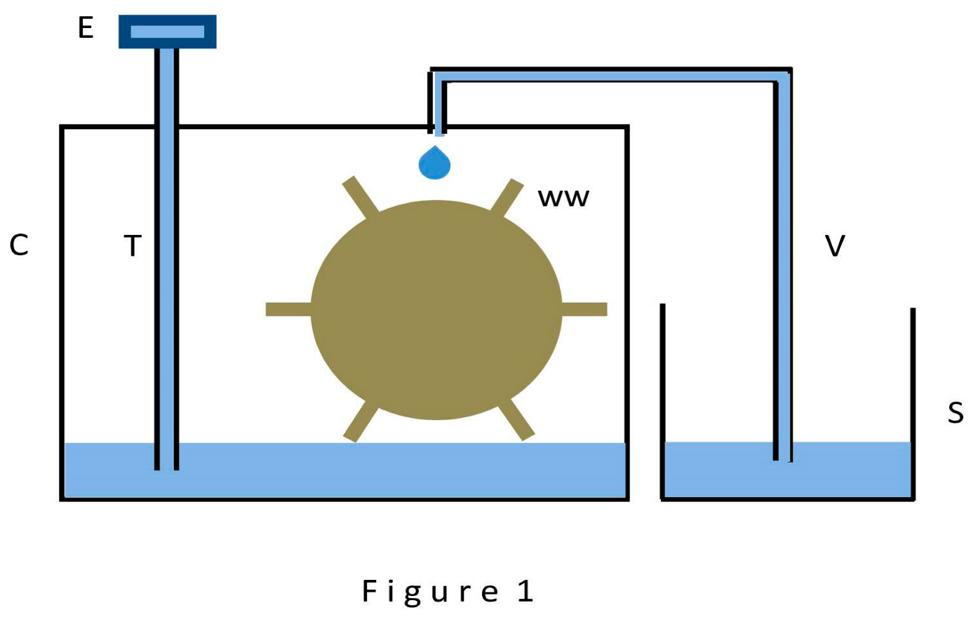
The following is a detailed description of both stages.
EXPERIMENTAL STAGE
The report of the experimental stage is given here from the phase of fabrication of the WWTD model. From the point of view of this proof, the process of finding the WWTD design has no practical interest.
Water movement in WWTD (Figure 1) is carried out along two independent routes. The first, transpiration, route is formed by a capillary T completely filled with water, the upper end of which is hermetically connected to the evaporator E, and the lower end is penetrated into the hermetically sealed cell C and is lowered into water, partially filling the cell. The second route - the route for the rise of passive water - is formed by a capillary B, the lower end of which is lowered into the water of an open source S, and the upper end is hermetically penetrated from above into the cell C so that the droplets of water sucked out of it fall precisely on the blades of the water wheel WW and make it to rotate and perform useful mechanical work. (In making the physical model, the mechanical detail of the water wheel was not envisioned and was left only to the imagination of the researcher. However, the concept of a water wheel turns out to be convenient in many of the considerations and the possibility of its presence is implied until the end of the paper). It was assumed that immediately after assembling such a structure, the process of water evaporation (transpiration) through the evaporator E begins, leading to the emergence and growth of rarefaction in the cell C, the suction of water droplets from the upper end of the capillary V and their falling onto the wheel WW (or falling down from a height within cell C, in the absence of a wheel). Successful testing of such a two-stream model becomes the first step in developing the proof.
The following goal was pursued when fabricating the physical model of the WWTD: the model should be easily reproducible in laboratory conditions, have dimensions convenient for measurements, and clearly demonstrate the dynamics of the passage of water streams along the routes. As a result, the model parameters turned out to be as follows. The only active element in the WWTD model is the transpiration unit or wick, formed in this case by the evaporator E and the capillary T. The parameters of the remaining elements depend almost exclusively on the suction power of the wick and its performance. It was decided to limit ourselves to the manufacture of a wick with a low suction force of the order of 200 millimeters of water column in absolute measurement. A simple calculation showed that a wick with such a suction force is able to provide simultaneously the rise of water through the capillary T to a height of 70 millimeters, through capillary V to 60 millimeters, and also to ensure the process of formation of droplets sucked out of the capillary V with an internal diameter of no more than 0.4 millimeter. (The heights of 70 and 60 millimeters were chosen for purely design reasons). To make a wick with such suction force, an ordinary round cotton wick with a diameter of 3 millimeters was used, which is still used in kerosene (oil) lamps. The wick was made in two steps.
In the first step, a capillary T with an internal diameter of 3 millimeters and a length of 200 millimeters was used. It was tightly filled along its entire length with a cotton wick in such a way the cotton wick remnant at least 20 centimeters long came out of the upper end of the capillary. From this remnant the evaporator E was made: it formed into a flat spiral as the wick remnant was wound tightly around a common center. Once the free surface of the spiral (both sides) available for water evaporation reached 1000 square millimeters, the remainder of the cotton wick was trimmed and the spiral was tightly fixed in a horizontal position perpendicular to the capillary T. This wick assembly technique guarantees a tight connection between the evaporator E and the water volume at the bottom of the cell C. The size of the area of the evaporator E (1000 square millimeters) was chosen to ensure a wick performance of at least 300 cubic millimeters of water per hour in laboratory conditions, which is necessary to ensure the visibility of the movement of water flows in the process of testing the model. The test of the wick was carried out within 72 hours after lowering the lower end of a capillary T into the water of an open source of water. Measurements have confirmed that the suction force of the evaporator E exceeds in absolute measurement 200 millimeters of water column (i.e. the height of the capillary T, to which the wick has to raise the source water, overcoming the rarefaction that occurs at this height), and its performance (the rate of transit and evaporation of water) in laboratory conditions satisfies the specified level - at least 300 cubic millimeters per hour.
In the second step, the capillary T was shortened to a length of 80 millimeters and the physical model of WWTD was finally assembled in accordance with Figure 1. The final dimensions became as follows. Capillary T hermetically penetrates cell C, its lower end is lowered into the water of the cell so that the evaporator E is 70 millimeters above the water level. The upper end of the capillary V with an internal diameter of 0.4 millimeter hermetically penetrates cell C from above, its lower end is lowered into the open source S so that the droplets sucked from its upper end into cell C are raised to a height of 60 millimeters relative to the source S.
The transpiration process started immediately after assembly of the model and was observed for at least 720 hours. It was characterized by high stability: evaporator E evaporated about 300 cubic millimeters of water per hour throughout the entire period, sucking it out of cell C and creating in it the rarefaction sufficient to suck water from the upper end of capillary V; exactly the same amount of water (300 cubic millimeters per hour) was released in the form of droplets, falling to the bottom of cell C from the upper end of capillary V so that the water level in the cell remained unchanged; the volume of water in the open source S was constantly decreasing at the same rate of 300 cubic millimeters per hour. The model transparently demonstrated a two-stream (and two-route) organization of the water movement process. Both routes operated simultaneously. Along the first route, the water moved through the capillary T to a height of 70 millimeters along the water negative potential gradient emerging in accordance with the Cohesion - Tension theory [2,3,4] in the process of water transpiration, and evaporated into the atmosphere in the evaporator E. Simultaneously, the same quantity of water rose along the second route along capillary V to a height of 60 millimeters and, having formed into droplets, could use its potential energy either to perform useful mechanical work (in the presence of a water wheel), or to convert this potential energy into kinetic energy (if there is no wheel) as it falls to the bottom of the cell C. Externally, the operation of the whole structure is reduced to continuous pumping of water from the source S to evaporate it into the atmosphere at a rate of 300 cubic millimeters per hour and to generate mechanical energy, which is released on the shaft of the water wheel WW. The first route in this case transparently turns out to be an engine that consumes the incoming water as a kind of fuel and gives up part of the generated energy to organize water ascent through the second route and transforming this energy into mechanical work performed by the WW wheel.
The literature search for experiments similar to the described one and for analogues of the WWTD, gave the following results. Despite the abundance of information on devices that utilize the phenomenon of transpiration to some extent, and the centuries-long history of such devices, there is no mention of experiments aimed at creating, by means of transpiration, a rarefaction in the source area of the supplied liquid (be it kerosene, oil, water or other liquid) and using this rarefaction to generate energy to raise liquid through a second route or to transmit this energy to external consumers, as is done by the WW wheel in the WWTD device. Analogues of WWTD should be considered devices of the following types: oil and kerosene lamps, known since ancient times [5], heat pipes and capillary pumps [6,7,8,9], known since the mid-20th century, synthetic trees [10,11,12], the active design of which began in the 21st century. The active element of the listed devices is the wick. In heat pipes and capillary pumps, the wick design no longer resembles the wick in the form in which it is used in lamps. In synthetic trees, the wick is formed by one or more capillaries, hermetically connected to an evaporator made of nanoporous material. In all of the above cases, the wick is an energetically advantageous element due to the process of constant evaporation of the liquid, which produces energy expended in the mechanical movement of the liquid or its vapor. In the case of lamps, this is the rise of liquid up the wick. In the case of heat pipes and capillary pumps, this is the forced movement of liquid and generated vapor along the extended bodies of these devices. In the case of synthetic trees, this is the rise of water to a given height (for evaporation). In all of the above devices, the movement of liquid (and the vapors) is carried out along a single route. This is the first difference between these devices and WWTD. The second difference is that none of these devices are used to utilize the rarefaction generated at the inlet for practical purposes. In lamps, the reason for the lack of such attempts lies, perhaps, in the weak amplitude of such a rarefaction. In the case of heat pipes and capillary pumps, the reason may be that the wicks here perform a “push” function in relation to vapor and condensate, and putting them to “pull” function is not of importance. In the case of synthetic trees, the work of a nanoporous evaporator may translate into a rarefaction at the base of the wick, close to a vacuum state and worthy of practical use. However, even in this case, there is no information about attempts of practical use of rarefaction. In general, the above mentioned allows us to speak about the novelty of the WWTD device.
ANALYTICAL STAGE
The analytical stage aims to transform the WWTD model first into a one-stage two-stream device, then into a multi-stage two-stream device.
The transformation of the WWTD model into the simplest one-stage, two-stream device is accomplished in two steps.
The first step results in the transitional structure shown in Figure 2. Here the capillaries T and V continue to fulfill their previous functions, but now obeying the actions of the locks L0 - L3, capable of hermetically closing water or air flows. There are already two hermetic cells C0 and C1 and two open sources S0 and S1 in the device. It is important to note that in the devices from Figure 2, there is a need to monitor the consistency of water level in the sources. To obviate this need, we will assume that the water level in the sources does not change during the course of the experiment. This can be achieved, for example, by using vessels with a significant open surface of water, so that small volumes of water entering or flowing from the sources (in our case it is 300 cubic millimeters per hour) do not lead to a noticeable change of the level. We will depict such sources as elongated open vessels, as in Figure 2. At the initial moment of time, it is assumed that the water level in cell C0 coincides with the water level in source S0, and the level in cell C1 coincides with the level in the source S1. With these reservations in mind, the operation of the device can be described as follows. When the lock L1 is open and the others are closed, the entire device is similar to the device in Figure 1, with the difference that water flows through the capillary V and (in the form of droplets) into the cell C1, located 50 millimeters above the cell C0, constantly accumulating in it, and the water level in the cell C0 is constantly decreasing due to its outflow through the capillary T into the evaporator E for evaporation into the atmosphere. When the lock L1 is closed and the others are open, water begins to flow from the source S0 into the cell C0 and from the cell C1 into the source S1. Water overflow is carried out by gravity: from the vessel with a higher level water flows into the vessel with a lower level. This flow takes insignificant time compared to the time spent on the slow process of transpiration. Such periodic acts of depressurization occurring, for example, once an hour and lasting a few seconds, cannot have a noticeable effect on the operation of the device; yet they allow to perform the important function of restoring the water supply in cell C0 and transferring excess water accumulated in cell C1 to the source S1. The height of 50 millimeters to which water is eventually raised from source S0 to cell C1 (and then to source S1) is chosen as follows. The maximum height to which water can rise through the capillary V in the second route is 60 millimeters. In order not to hinder the process of droplets formation, we assume that the water level in cell C1 is 10 millimeters below these 60 millimeters, that is, at a level of 50 millimeters above the water level in source S0. As a result, the operation of the device as a whole is reduced to continuous lifting of passive water from the source S0 by 50 millimeters upward into the source S1.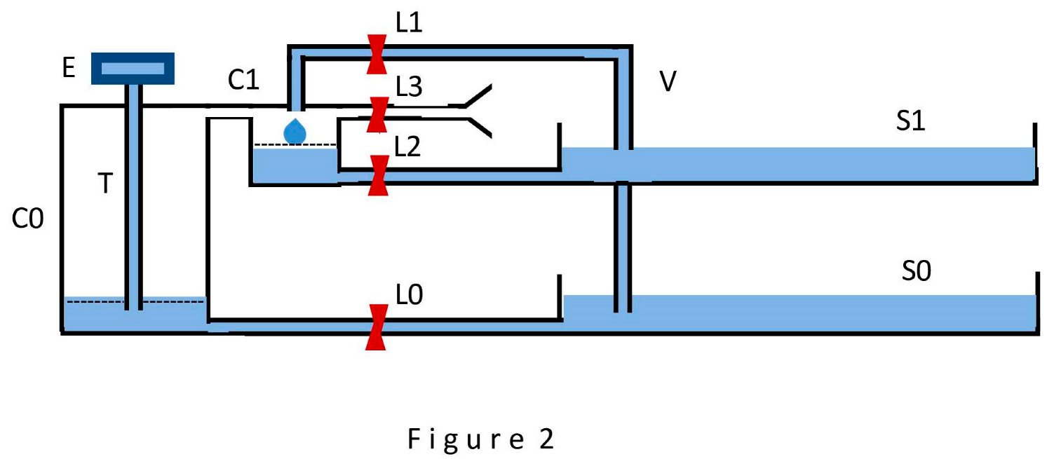
This step consists in abandoning the obviously artificial drip method of water transfer from the source S0 to the cell C1. Capillary V in Figure 3 connects the water volumes of source S0 and cell C1 directly. The process of water movement in this case is described in the following expressions. With the lock L1 open and L0, L2, L3 closed, the movement of water from source S0 into cell C1 will always occur when the rarefaction in the cell C1 (as well as in the cell C0) will exceed by absolute value the pressure in the water column inside the capillary V (taking into account the thickness of the water layer in the cell C1). When the water level in cell C1 reaches the dotted line (the water level in cell C0 decreases at the same rate), the slow movement of water in the device is interrupted, and a short period of its depressurization is started (lock L1 is closed, L0, L2, L3 are open), as a result of which the water levels in cells C0 and C1 are restored, while the portion of water raised into cell C1 flows into the source S1, the consumer of the raised water.
As a result of the transformations, Figure 3 shows a schematic of a simplest device for raising water to a limited height. This device solves the problem of continuously raising water to a height of 50 millimeters from source S0 to source S1. The task of switching the L0 to L3 locks correctly in laboratory conditions may well be left to the operator, which does not contradict the objectives of this proof. In the case of experiments of long duration, it is also incumbent on the operator to maintain water level constancy in the sources S0 and S1 for long periods of time. This device turns out to be a two-stream (and two-route) device. The first route performs the function of an engine that provides energy for the movement of water through the second route. The water at the second route outlet is always available at normal atmospheric pressure. Also, this device is one-stage device, each portion of water in it rises in one step directly to the maximum height, 50 millimeters.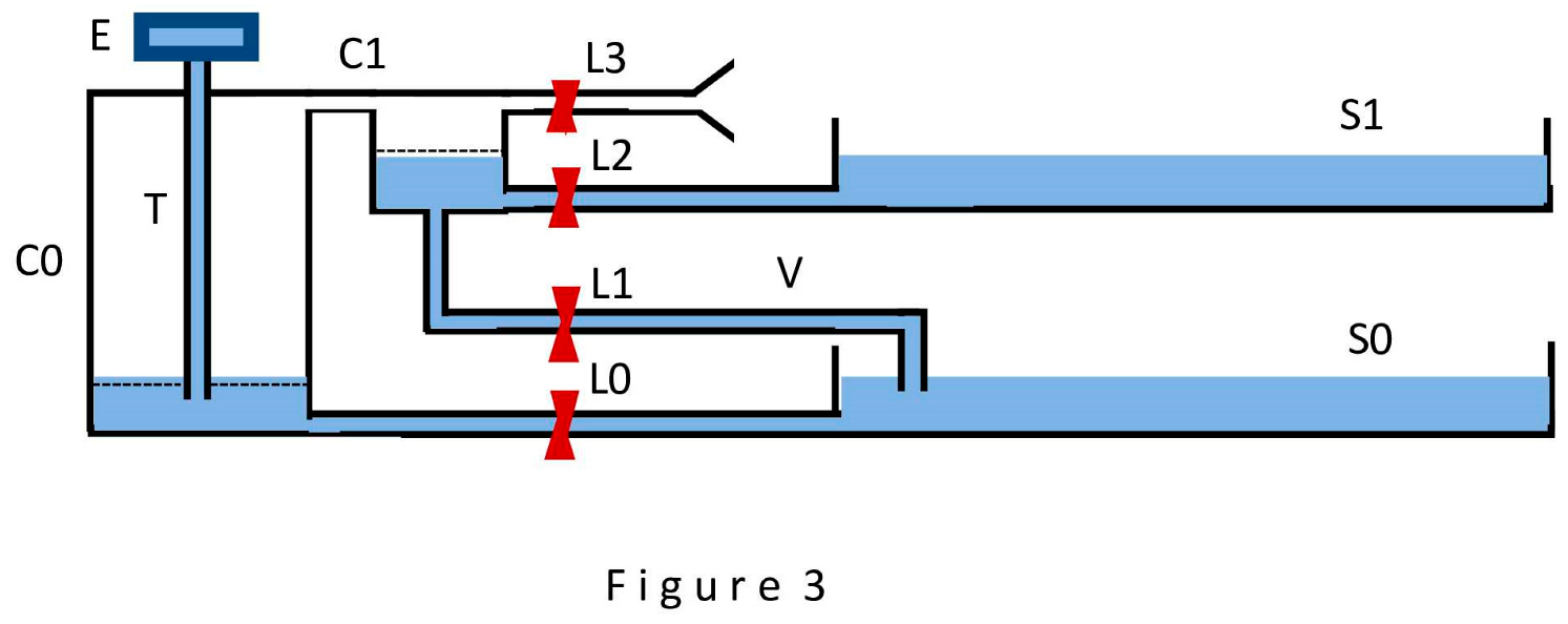
One-stage devices cannot raise water to a height of more than 10 meters, because the rarefaction in the cells C0 and C1 cannot exceed the state of full vacuum. The only way to continue transformations in order to build a model of water raising to any given height is the way of building multi-stage device, when each next stage raises water to a limited height, but the number of stages can be unlimited. Taking this path, we assume that all stages of the multi-stage device are identical and are described in Figure 3, and that each stage is capable of raising water exactly 50 millimeters.
The easiest and most transparent way to build a multi-stage model is in the case where there are many copies of one-stage device shown in Figure 3. In this case, it is enough to place these devices in a vertical order one above the other by exactly 50 millimeters (that is, by as much as the device in Figure 3 raises the transferred portion of water) and connect them in such a way that each device takes a portion of water at the outlet of the previous device and, in the process of transpiration, transfers it to the input of the next device (this water is under normal atmospheric pressure). As a result, each portion of water will overcome as many steps of ascent as there are copies of the device.
In our proof, we turn to another variant of constructing a multi-stage device which is more convenient to consider in a short article.
The transition from a one-stage device (Figure 3) to a multi-stage one in this variant is accomplished by increasing the complexity of the switching mechanism and the number of cells and water sources. Figure 4 shows a schematic of a four-stage two-stream device, the final goal of the transformation. The choice of four stages is not accidental: this even number allows to build considerations that can be easily transferred to devices with any number of stages, avoiding the development of more complex structures.
Multi-stage devices are capable of raising water step by step (in our case, by 50 millimeters each time) in several ways. The serial and serial-parallel ways should be considered as the main ones. In the first case, the transfer of portions of water is carried out sequentially from the first stage to the second, then from the second to the third, and so on until the top stage. This method turns out to be simple to understand, but extremely slow in the case of a large number of stages. In the second case, the transfer of portions of water is carried out in parallel (that is, simultaneously) in a large part (in the extreme case, in half) of the stages, which greatly accelerates the process of water movement upwards. Figure 4 is suitable for describing both of these methods; each method is realized by appropriate organization of the switching mechanism operation (locks L0, L11 - L43).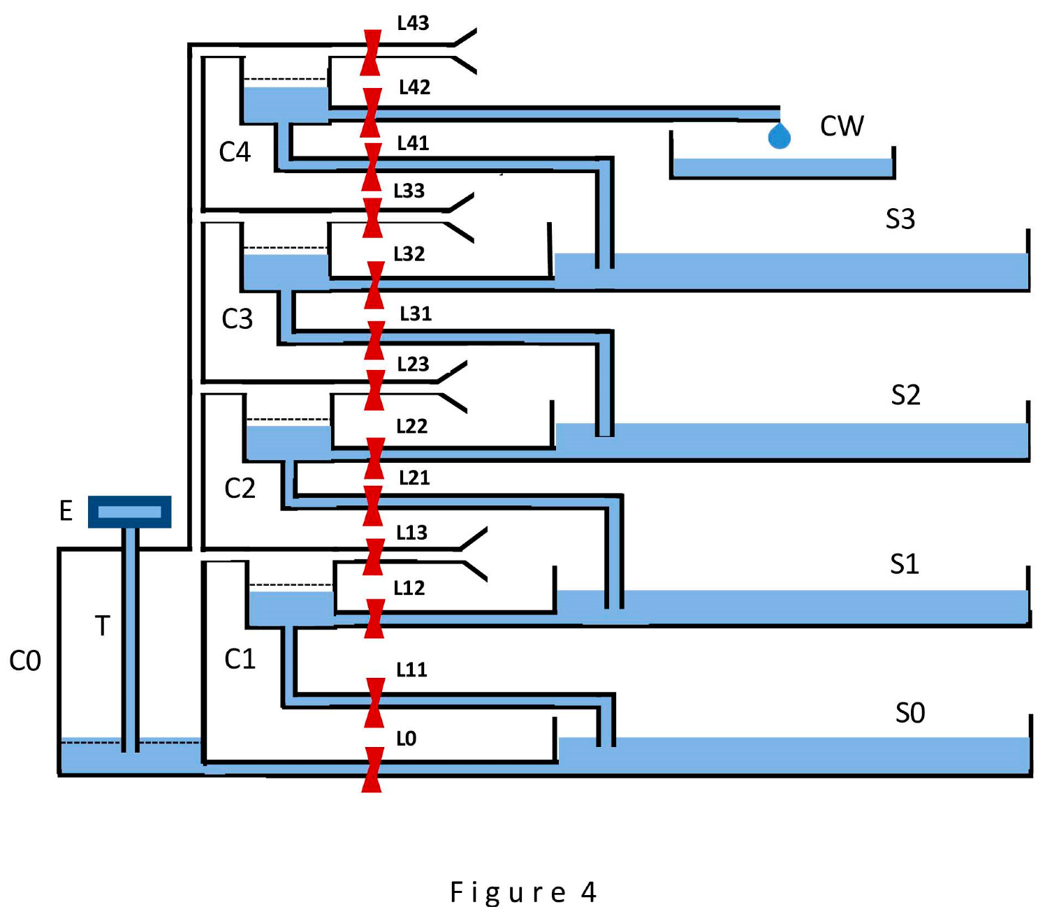
At this point, it is necessary to make a general remark. Only the second route, the passive water rise route, undergoes transformation into a multi-stage design; the design of the first route remains unchanged. Accordingly, as the number of stages increases, the height of the device increases only in part of the second route; the evaporator E of the first route invariably remains at a constant moderate height above the source S1. In turn, the issue of the final consumer of the raised water is, for simplicity, addressed as follows. In Figure 4, the final consumer of water is a CW vessel. It is assumed that it is capable of consuming unlimited quantities of water entering it by gravity after opening the L42 lock, and this does not lead to a noticeable increase in the water level in it. It should be repeated that water enters the CW unit at normal atmospheric pressure.
The implementation of a serial method is achieved by the following control organization of the switching mechanism in Figure 4. It is assumed that the whole device is in a steady-state process, and all sources S0 - S3 have a steady-state water supply. To raise a portion of water from source S0 to the first stage in the first step, lock L11 is opened, the rest remain closed. The rarefaction transmitted from cell C0 to cell C1 causes the water from source S0 to rise into cell C1, gradually raising the level in it to the dotted line. Once this line is reached, lock L11 is closed and locks L0, L12, L13 are opened for a few seconds. During these few seconds, the water levels in cells C0 and C1 are restored, and the volume of source S1 increases due to the portion of water coming from cell C1. To raise this portion from source S1 to the second stage in the second step, lock L21 is opened, the rest are closed. Immediately (after the rarefaction in the cells is restored), water begins to rise from source S1 to cell C2, and all the actions described for the first stage in the first step are performed. As a result of the second step, a portion of water is transferred to the source S2. This process continues until, at the last, fourth step, a portion of water is transferred to the consumer CW. This scheme for transferring a portion of water is valid in structures with any specified number of stages.
The implementation of the serial-parallel method (the option of raising water simultaneously in half of these four stages) is achieved as follows. At each odd step, locks L11, L31 are opened, the rest are closed. The rarefaction growing in cell C0 and transmitted to all other cells causes water from sources S0 and S2 to flow into cells C1 and C3. After the water level in cells C1 and C3 reaches the dotted lines, locks L11 and L 31 are closed, and locks L0, L12, L13, L32, L33 are opened for a few seconds to restore the water level in the cells while simultaneously transferring portions of water to the sources S1, S3. At each even step, locks L21, L41 are open, the rest are closed. Now portions of water flow from sources S1 and S3 into cells C2 and C4. After the water level in them reaches the dotted lines, locks L21 and L41 are closed, and locks L0, L22, L23, L42, L43 are opened for a few seconds to restore the water level in the cells with simultaneous transfer of portions of water to the source S2 and the consumer CW. Thus, each successive portion of the raised water reaches the final consumer CW at every second step, rather than at every fourth step, as in the serial method. When the number of stages is increased, for example, to 40, each successive portion of water will still flow to the final consumer CW at every second step. This can be easily verified by transferring the above reasoning to the case of 40 stages. With this serial-parallel method of raising water, the portion of water transferred from stage to stage inevitably decreases (it is assumed that evaporator E continues to evaporate, regardless of the number of stages, a constant volume of water, 300 cubic millimeters of water per hour, as in the case of WWTD). So, in the case of four stages, this portion will be two times less than in the case of one stage, and in the case of 40 stages - 20 times less.
The above considerations are easily transferred to devices with an arbitrary even number of stages, and there is no need to depict their schematics in separate figures. Both devices (one-stage and multi-stage) are modified versions of WWTD and their operability is proven as a consequence of the operability of the WWTD model, manufactured and tested at the experimental stage.
Thus, the possibility of developing an ATD capable of raising passive masses of water to any given height, maintaining normal atmospheric pressure in them, can be considered proven.
CONCLUSIONS
Starting to analyze the value of the proof, we first find out the position occupied in the world of active elements by the three developed devices (WWTD, one-stage and multi-stage devices, shown in Figures 1, 3, 4). Under the conditions of the proof, all three have the ability, unaided, to raise 300 cubic millimeters of water per hour to a height of 50 millimeters, that is, to develop a power of about 0.04 microwatt, part of which can be taken away as energy gain. (The concept of the water wheel as a part of WWTD helps to understand the meaning of the last words). Despite the small power value, these devices can find application in practical areas, for example, as autonomous sources of microscopic power energy. However, attention is drawn to a different approach to evaluating the results obtained. Let us comment on the power of the three devices, by comparing it with the power developed in the process of natural transpiration by one leaf of a tree capable of raising 200 liters of water during 15 hours of daylight to a height of 20 meters, which coincides with the average productivity of real trees on the planet [13]. It is easy to calculate that such a tree develops a power of about 0.7 watt during daylight time. Assuming that the crown of such a tree contains 200,000 leaves, we find that one leaf during the process of transpiration develops a power of about 3.5 microwatts, that is, a power of the same order as that of our devices. (The compared powers - 0.04 and 3.5 microwatts - differ by almost 90 times, that is, in a very noticeable way; however, this difference is due to the use in our devices, to simplify the proof, of an evaporator of the simplest design, made of a cotton wick, and in case of modification, their power can approach the power of one leaf of a tree and even exceed it). This comparison leads to the following important conclusion. The analysis of the value of the obtained results should be carried out on the grounds of not so much individual ATD devices, but on the grounds of large systems built from many thousands of such devices, just as one tree contains many thousands of leaves. In other words, it is necessary to carry out the analysis, focusing it on the use of large artificial transpiration two-stream systems (ATTSS), containing many thousands of devices similar to our devices, and capable of raising water in volumes worthy of practical use to any given height.
The potential value of the proposed large ATTSS, copying the world of trees, is logical to evaluate with an eye to the value of the real trees themselves in the world. In recent years, a quantitative assessment of the work performed by living plants on the planet (mainly trees) in the process of transpiration when soil water rises to the height of the canopy has been carried out [14]. In total, the energy expended by plants turns out to be comparable to the energy obtained from all hydroelectric power stations existing in the world. This impressive estimate can serve as a guide in determining the expediency of developing ATTSS. Unlike living trees, in the case of ATTSS there is no need to expend transpiration energy solely on raising water to the height of the canopy; this energy can be almost entirely taken from ATTSS as clean energy for practical human use. So, despite the weakness of individual parts of ATTSS, the totality of such systems can make a significant contribution to the production of environmentally friendly energy.
The second use of ATTSS is suggested by their ability to raise significant masses of water to a significant height without the use of external energy sources, keeping the water at normal atmospheric pressure. This ability is particularly useful in the construction of water storage stations. Examples include water towers for a wide variety of purposes, installed in unsettled locations and used for irrigation of arid land and for firefighting, as well as installations for lifting water from underground sources.
References
- Sterling, T. Transpiration: water movement through plants Journal of Natural Resources and Life Science Education, Volume 34, Issue 1, p. 2005. [Google Scholar] [CrossRef]
- Dixon, H. , Joly J. On the ascent of sap. Ann. Bot. 1894, 8, 468–470. [Google Scholar] [CrossRef]
- Kim H, Park J, Hwang I. Investigating water transport through the xylem network in vascular plants Journal of Experimental Botany, Volume 65, Issue 7, 2014, pp. 1895 – 1904. pp. 1895 – 1904. [CrossRef]
- Galston, A. , Satter R. The life of the green plant Benjamine Comings ( 1980.
- Thuro C. Oil lamps: the kerosene era in North America Echo point books & media (2018).
- Ivanovskii, M. , Sorokin V., Yagodkin I. C: The physical properties of heat pipes Oxford, 1982. [Google Scholar]
- Maydanik, Y. Loop heat pipes. Appl. Therm. Eng. 2005, 25, 635–657. [Google Scholar] [CrossRef]
- Nemec, P. Heat removal from bipolar transistor by loop heat pipe with nickel and copper porous structures. The scientific world journal, Volume 2014, ID 724740. [CrossRef]
- Zimmermann, M. , Schmid H. , Hunziker P., Delamarch E. Capillary pumps for autonomous capillary systems Lab on a Chip 2007, 7, 119–125. [Google Scholar] [CrossRef]
- Eyegheleme, N. , Peng K., Boreyko J. Modeling transpiration in synthetic trees International Journal of Heat and Mass Transfer, Volume 183, Part B (2022). [CrossRef]
- Wheeler, T. , Stroock A. The transpiration of water at negative pressure in a synthetic tree Nature 455, 208 – 212 (2008). [CrossRef]
- Shi, W. , Dalrymple R., McKenny C., Morrow D., Rashed Z., Surinach D., Boreyko J. Passive water ascent in a tall, scalable synthetic tree Sci. Rep. 10, 230 (2020). [CrossRef]
- Wullschleger, S. , Meinzer F., Vertessy R. A review of whole-plant water use studies in tree Tree Physiol. 1998 Aug – Sept; 18 (8_9): 499 – 512. [CrossRef]
- Quetin, G. , Anderegg L., Konings A., Trugman A. Quatifying the global power needed for sap ascent in plants (2022) Journal of Geophysical Research: Biogeosciences 127 (8). [CrossRef]
Disclaimer/Publisher’s Note: The statements, opinions and data contained in all publications are solely those of the individual author(s) and contributor(s) and not of MDPI and/or the editor(s). MDPI and/or the editor(s) disclaim responsibility for any injury to people or property resulting from any ideas, methods, instructions or products referred to in the content. |
© 2024 by the authors. Licensee MDPI, Basel, Switzerland. This article is an open access article distributed under the terms and conditions of the Creative Commons Attribution (CC BY) license (https://creativecommons.org/licenses/by/4.0/).
Copyright: This open access article is published under a Creative Commons CC BY 4.0 license, which permit the free download, distribution, and reuse, provided that the author and preprint are cited in any reuse.


