
Submitted:
29 April 2024
Posted:
01 May 2024
You are already at the latest version
Abstract
An important issue concerning the inspection of the technical condition of electrical power components and systems is thermal imaging investigation. This paper presents how the thermograms obtained from these measurements should be interpreted correctly according different standards and how operators should react when a specific anomaly is detected. It is also a review article in which all currently applicable international standards are referred to. The motivation of the article relates to the fact that these standards seems to be too general and not cover all practical situations even though in many countries thermal imaging diagnostics of overhead lines or overhead outdoor and indoor power stations has been used for years on the basis of industry standards or good practices. The purpose of writing this article is precisely to encourage and provoke the global community of metrologists, scientists and engineers involved in thermographic measurements to discuss, strengthen efforts and establish relevant international standards for the interpretation of thermograms containing the relevant temperature anomalies.
Keywords:
electrical power system
; thermographic measurements
; standards in thermovision measurements
; thermographic diagnostic
; interpretation of thermograms
1. Introduction
Wherever any cause generates heat, thermal imaging measurements become an indispensable diagnostic tool [1,2,3,4]. Thermal imaging can be effective method for tracking various processes whose course is associated with changes in emissivity or temperature over time or with variations in the thermal images of individual objects [5,6]. To assess, for example, the type of damage in electrical installation on the basis of thermograms, it is additionally necessary to carry out numerous tests and comparative analyses. A comparison with X-ray methods comes to mind here, where, without being a specialist, it is not possible to properly interpret an X-ray image. In the field of thermal imaging measurements, as in X-ray, specialization is also required, taking into account the characteristics of the individual fields of application and the ability to perform examination, and interpret correctly the results [7,8].
In general, it can be said that thermal imaging measurements in power engineering among others, are used for [9]:
- -
- detection of cracks and material inhomogeneities,
- -
- detection of thermal bridges in the insulation of electric furnaces, overheating points due to damage to the insulation of chamber furnaces, continuous furnaces, melting furnaces, dryers, boilers and pipelines,
- -
- testing of internal combustion engines and turbines,
- -
- wind turbines integrity testing,
- -
- -
- -
- -
- testing photovoltaic panels and installations [13].
- -
- In the process of inspecting and assessing the condition of power line components, thermal imaging measurements can furthermore be used to, among other things:
- -
- detecting overloads, damage or partial ruptures of cables,
- -
- detection of load asymmetry,
- -
- detection of leakage occurring on the insulation surfaces,
- -
- the ongoing monitoring of the correct functioning of transformers.
- -
- It should be noted that the lists given above is not fully exhaustive. The fault reason can be:
- -
- insulation deterioration and aging [12],
- -
- surface or internal cracks,
- -
- external pollution,
- -
- excessive ambient temperature,
- -
- weak mechanical connection,
- -
- partial short circuits,
- -
- eddy current,
- -
- cooling system failure,
- -
- wear of electric brushes.
- -
- semiconductor failure (photovoltaic panels) [12].
It is not possible to include a full description of possible applications within the limited framework of this article. Some of these examples particularly related to electrical power engineering are discussed in more details below. The examples given are only a modest illustration of the area and it is to be believed that specialists in the respective fields of knowledge will be able to considerably expand the field of application of thermal imaging measurements. Furthermore, it should be emphasized that thermal imaging measurements are a complementary method to other diagnostic methods [10,11,14].
2. Discussion on Thermal Imaging Diagnostics in Electrical Power Engineering
Some examples of applications of thermographic testing in electrical power engineering are given in Figure 1. The places with increased temperature are caused by weak connection - Figure 1a,1b and 1d - or leaking effects – Figure 1c. One of the most commonly used measurements is that of connectors on 110, 220 and 400 kV transmission lines. The subjects of the tests are the lashing clamps on the immunity poles - Figure 1d - and the mid-span connectors. Thermal imaging methods can also be used to determine the location of overheating at a disconnected or pressed connection of a line wire. The use of a helicopter to fly around the line makes it possible to inspect a significant length of electric line at one time and obtain results in a relatively short time.
When applying IRT (InfraRed Thermography) to the condition monitoring and diagnostics it is strongly recommended that severity assessment criteria be established [15]. In practice no singular severity assessment criterion is universally applicable to the variety of situations needed to be considered. These criteria can be general categories that identify temperature levels, versus levels of criticality or applied to specific components. First approach is checking the measured temperature is lower or not that absolute temperature limit given in the technical documentation for tested element. It should be noted that the temperature of line components is very much influenced by atmospheric conditions changing the heat transmission between object and surroundings. For example, Figure 2 shows the effect of wind on the temperature difference between the clamp and the conductor. It can be seen that the wind velocity has a significant effect on the temperature difference for the same current load. For example, for current load I=500 A and wind speed v=7.2 m/s, i.e. almost 26 km/h, the temperature rise can be six times lower than for no wind conditions. Another weather factor causing similar effects are rainfall or snowfall. Therefore, conclusions based on the temperature reading without taking into account other factors may lead to incorrect assessments and decisions. Furthermore, there are also other relevant factors related to the drawback of thermography like influence of emissivity of the surface of tested object on temperature readings, reflected radiation of other objects, small difference between object and ambient temperatures, air transparency decreased by fog, some contaminating gases or smokes.
Thermal imaging measurements are most often used to determine the condition of an electrical wires after many years of use, when, due to ageing effects, it becomes covered with a oxide or contamination layer of relatively high emissivity. In the case of thermal imaging measurements carried out on a new line, the thermogram obtained does not fully reflect the thermal condition of its components. There are much greater differences in emissivity coefficients and stronger radiation reflections in the new elements, recorded by the camera on the thermogram. This often masks the real technical condition. This causes considerable difficulty in relying on absolute maximum permissible temperature criterion [15] due to high uncertainty of such measurement. In paper [16] ambient, rated and maximal temperatures for different material used to build the electrical components as PVC), polyethylene, silicone rubber, connectors and terminations (copper, copper alloy or aluminum), fuses, coils and relays are given and discussed.
Therefore, it is most often not the temperature of the power line element under test that is important, but the temperature difference between a damaged and a good element. Another solution is comparing measurement with historical data taken for the same environmental and operational conditions. Generally, these difference temperature criteria are usually reported as the temperature rise of the anomaly above the temperature of a defined reference. By taking multiple measurements of similar components over time, statistical analysis can be used to set operational limits for trending and predicting the temperature performance [15].
There will be discussed some approaches taken from published papers an standards. Practical criteria for evaluating the results of measuring the temperature differences between a good and an overheated clamp (contact or joint) are given in Table 1 [17]. Based on these criteria, it can be determined whether there is a need for immediately replacement or repair (IMM), it can be done later, for example during next scheduled maintenance (UR). Determining the line load is crucial, as the temperature rise is proportional to the square of the current rise: ΔT~(ΔI2) and high temperature can be accepted as being normal for high currents. For correct assessment we need to consider percentage of nominal current load, wind speed and registered by IR camera temperature rise. As discusses previously due to effect of object cooling by wind, for higher wind speeds the lower temperature differences are indication for technical review an maintenance. For example, for a measured temperature rise of ΔT=20K at a 40% of a rated load, if the load is twice as high - 80%, the temperature rise will be 4 times higher and will be ΔT=80 K.
2.1. Low-Voltage Installations
Slightly different recommendations and criteria presented in Table 2 and Table 3, are given in the work [18]. The study assumes that the load remains constant for at least 45 minutes before measurements are taken and meantime in work [19] 15 minuts is suggested as being enough to obtain stready state and constant temperatures. The German VDE standard [20] states 15-30 min for low-voltage and 15-60 min for high-voltage oinstallations up to 20kV. As we see there exist a least few proposals on it and therefore this issue is needs further analysis and discussion.
In addition, the measurements should be carried out at the time of the highest possible current load. The measurements can not be performed if tested element is conducting a negligible current, i.e. under 20% of nominal load according to the authors [19].
Three general indications are commonly accepted, signalling the need to repair the equipment, i.e. if:
- -
- for a symmetrical three-phase load, a temperature difference between clamps on three neighbouring phases ΔT >3 K,
- -
- clamp and ambient temperature difference T – To>35 K,
- -
- clamp temperature T >70 OC.
In many situation the condition on nominal load is not met. Furthermore the temperature rise is affected by condition of heat transfer to the surroundings. These both factors are consdered in work [18] and two methods are recommended for determining the severity of overheating. To apply them, the value of the current load I of the installation must be known.
Method 1. Table 2, is used in three-phase systems for symmetrical loading of each phase line. The measured temperature difference between the overheated and good phase ΔT, for the current load I, is converted into a temperature difference ΔTn, corresponding to the nominal load in according to the formula:
where:
k = 1.6 ÷ 2.0 - exponent depending on heat transfer conditions, i.e. weather condition: k = 1.6 - good, k = 1.8 - fairly good, k = 2.0 - poor heat transfer conditions.
Method 2. The second method is used in single-phase and three-phase installations when there is load asymmetry in individual phases. It can be used to determine whether the permissible temperature has been exceeded at a given clamp, for a given load I. In this case, the reference temperature is the ambient temperature To.
If overheating occurs in a closed switchboard (panelboard switchgear), the switchboard must be kept closed until the temperature of the overheated clamp reaches a constant value. The switchboard is then opened and the temperature of the overheated terminal is measured immediately. The measured temperature difference between the overheated phase temperature T and the ambient temperature To, for the current load I, is converted into a temperature difference ΔTon, corresponding to the rated load In, according to the formula:
where:
T, To - clamp and ambient temperature for the current load I, K,
Tn, Ton - clamp and ambient temperature for rated load In, K.
The permissible values of ΔTn are specified in Table 2.
In paper [21] an another, this time linear formula has been obtained for the temperature of the hot spot as a function of the current. It allows to evaluate the temperature that would be reached if the nominal current circulated through the circuit. The drawback of it is that heat conditions are not considered as previously.
2.2. High-Voltage Installations
In this case, a distinction is made between two types of clamps: shielded and uncovered. The values for permissible temperature rise are given for them in Table 3. What can be surprosing in contrast to the low-voltage installations the another fault classes are defined. Instead of 3 classes only two are propossed – the last class "observe” is removed. This is justified by more difficult condition for technical inspections and finally higher costs and even fully confirmed by experience of the authors of this manuscript conducting this kind of inspections for power transmission lines in Poland.

Table 3.
Assessment of the need to repair clamps and conductors of high-voltage power lines based on the calculation of the temperature rise ΔTn for the rated load In [18]. abbreviations: UR - urgently, NSSI – during the next scheduled service inspection
Table 3.
Assessment of the need to repair clamps and conductors of high-voltage power lines based on the calculation of the temperature rise ΔTn for the rated load In [18]. abbreviations: UR - urgently, NSSI – during the next scheduled service inspection
| Fault class | Shielded connection | Exposed connection | ||
|---|---|---|---|---|
| ΔTn, K | Recommendations | ΔTn, K | Recommendations | |
| 1 | > 3 | UR | > 20 | UR |
| 2 | 1 – 3 | NSSI | < 20 | NSSI |
Example
Let us consider the measurement situation shown in Figure 3. We will test the middle phase as its temperature is much higher than right-side reference pahase. According to equation (1), let us assume the most unfavorable value of k = 2 - bad heat transfer conditions and that:
- there is a 50 % load on each phase
Considering the values given in Table II, the result obtained indicates that repairs should be carried out immediately ‘IMM’.
- there is a 100 % load on each phase
Considering the values given in Table II, the result obtained indicates that repairs should be carried out urgently ‘UR’.
- there is a 200 % load on each phase
Considering the values given in Table 2, the result obtained already indicates the need to observe ‘O’ for this pair of electrical wires.
For low- and high-voltage installations, certain deviations from the values of permissible temperature increases ΔTn indicated in Table 1, Table 2 and Table 3 are acceptable as fitted to the technical and financial circumstances. These factors are the possibility of obtaining higher loads (which is associated with an increase in the temperature of the junction), the technical and organizational feasibility of shutting down the field (daily service operations, weather conditions), financial consequences of failure or shutdown for maintanance. As stated in the introduction, the main purpose of this article is to encourage discussion with a view to developing relevant international standards for the interpretation of thermograms obtained from thermovision measurements and how operators should react when a specific anomaly is detected. This is because it appears that the guidelines in this respect given, for example, in other standards as an example provided in [22] - Table 4, seems to be really insufficient and not covering real life occurring situations. The most questionable seems to making decision on criterion with low temperature levels as 1-3 K presented in Table 3 and Table 4. The measurements of so low differences is difficult with high uncertainty due to limited accuracy of IR camera, comparison to reference object working in the same conditions and load. The key issue, as mentioned in the standard itself, are qualifications of the person performing the electrical inspection that must be thoroughly trained and experienced concerning the apparatus and systems being evaluated as well as knowledgeable of thermographic methodology [22].
An even different interpretation of the anomalies obtained from thermal imaging measurements is presented in the works [20,23] - see Table 5. These recommendation are obligatory for example only in selected countries like Germany and open question is how do they correspond to others presented in above tables. Are they more realistic being better suited to practical cases? Obviously, relying on first class reported as 0 < ΔT < 10 K is more resist and protecting against false indication for maintenance – unjustified and costly shutdowns and repairs.
3. Future Directions
Existing well accepted standards are very general and are not enough supporting the needs of examination of components of electrical power systems. For example the standard [24] describe mainly the standard terms. The documents [25,26] provide general principles for infrared thermographic testing in the field of industrial non-destructive testing. The standards [27,28] are focused on features and properties of experimental instruments. The following items are specified: objective lens, detector, image processor, display, thermal stimulation source, accessories. The procedure for examining electrical equipment with infrared thermography is also very general and not relating to high voltage power engineering, unfortunately. More constructive discussion and arrangements are needed to set a valuable standard. It is worth noting that the lack of such standardization of existence too many standards is very inconvenient when interpreting results obtained from thermal imaging measurements. This is clearly illustrated in the work [29] showing this problem from the insurance company’s point of view. Another issue that defies attempts at standardization is data pre- and processing data techniques for obtaining reliable and repetitive results. As stated in [9] with the increase of manpower cost and the expansion of system scale, automation and intelligence are the inevitable trend of the development of IRT of power equipment. The problem are related not only with sophisticated techniques as deep learning methods [30,31] but relatively simple techniques used for image pre-treatment, image segmentation, target identification, temperature information extraction, fault identification and diagnosis [9]. This is caused by influence of chosen techniques and their parameters on the final results.
4. Conclusions
The conclusion on future work is as follows – we have to continue research on finding solution being included in international standards and fully acceptable by industry. Today, there are at least several standards in force presenting different approaches to the assessment of anomalies in which different temperature thresholds are used. Because trying to generalize, if not impossible, at least seems to be very difficult. A rational solution seems to be the preparation of standards dedicated to specific types of facilities or devices in the area of power engineering because we have to remember the basic principle that decision on repairing belongs to the owner or manager of installation or facility.
Author Contributions
“Conceptualization, W.M. and S.G.; writing—original draft preparation, W.M.; writing—review and editing, S.G.; supervision, W.M, funding acquisition, S.G. All authors have read and agreed to the published version of the manuscript.”.
Funding
This work was developed within the framework of the project PM-II/SP/0003/2024/02 entitled Standardization of the Procedure for Defect Dimensioning by Active Infrared Thermography, and co-financed from the Minister of Education and Science, Poland under the program “Polish Metrology II”, amount of funding: PLN 910,690.00, total value of the project: PLN 910,690.00.
Conflicts of Interest
The authors declare no conflict of interest.
References
- Minkina, W. , Dudzik S. Infrared Thermography – Errors and Uncertainties; John Wiley & Sons Ltd, Wiley – Blackwel: Chichester, 2009, https://www.wiley.com/en-us/Infrared+Thermography:+Errors+and+Uncertainties -p-9780470682241; ISBN 978-0-470-74718-6. [Google Scholar]
- Minkina, W. Theoretical basics of radiant heat transfer – practical examples of calculation for the infrared (IR) used in infrared thermography measurements. Quantitative InfraRed Thermography Journal 2021, vol. 18, no. 4, pp. 269-282. https://www.tandfonline.com/doi/full/10.1080/17686733.2020.1738164.
- Minkina, W. How Infrared Radiation Was Discovered – Range of This Discovery and Detailed, Unknown Information. Applied Sciences 2021, vol. 11, no. 21, pp. 1-14. [CrossRef]
- Minkina, W. , Dudzik S. Simulation analysis of uncertainty of infrared camera measurement and processing path. Measurement 2006, vol. 39, no. 8, pp. [CrossRef]
- Więcek, B. , De Mey G. Termowizja w podczerwieni – podstawy i zastosowania. (Infrared thermal imaging - fundamentals and applications); Wydawnictwo PAK, Warsaw, Poland, 2011, ISBN: 978-83-926319-7-2 (in Polish).
- Budzier, H. , Gerlach G. Thermal Infrared Sensors – theory, optimisation and practice; John Wiley & Sons Ltd, Wiley – Blackwell, Chichester, Great Britain, 2011, ISBN 978-0-470-87192-8. https://www.wiley.com/en-us/Thermal+Infrared+Sensors%3A +Theory%2C+Optimisation+and+Practice-p-9780470976753.
- ISO. ISO 18436-7, Condition monitoring and diagnostics of machines - Requirements for qualification and assessment of personnel - Part 7: Thermography. International Organization for Standardization, 2014 (reviewed and confirmed in 2019).
- ISO. ISO 9712, Non-destructive testing - Qualification and certification of NDT personnel, International Organization for Standardization, 2021.
- Xia, C. , Ren M., Wang B., et al., Infrared thermography-based diagnostics on power equipment: State-of-the-art. High Voltage 2021, vol. 6, pp. 387–407. [CrossRef]
- Minkina, W. Problems of remote temperature measurement of small objects of electricity power systems - on the example of lashing clamps of bridge connections on high voltage poles. Energies 2021, vol. 14, no. 16, pp. 1-11. https://doi.org /10.3390/en14165041.
- Gryś, S. , Minkina W. Noninvasive methods of active thermographic investigation: short overview of theoretical foundations with an example of application. Energies 2022, vol. 15, 4865, pp. 1-22. [CrossRef]
- Bolun Dua, Yigang Hea, Yunze Heb, Chaolong Zhang. Progress and trends in fault diagnosis for renewable and sustainable energy system based on infrared thermography: A review. Infrared Physics and Technology 2020, vol. 1033; 83. [CrossRef]
- IEC. IEC TS 62446-3. Technical specyfication. Photovoltaic (PV) systems – Requirements for testing, documentation and maintenance – Part 3: Photovoltaic modules and plants – Outdoor infrared thermography, International Electrotechnical Commission, 2017.
- Madding R. P., Orlove G. L., Lyon B. L. The importance of spatial resolution in IR thermography temperature measurement – three brief case studies. In Proceedings of the InfraMation Proceedings, 22.05.2006, ITC 115 A.
- ISO. ISO 18434-1:2008(E), Condition monitoring and diagnostics of machines — Thermography. Part 1: General procedures, International Organization for Standardization, 2008.
- Hadziefendic, N. , Trifunovic J., Zarev I., et al. The importance of preventive thermographic inspections within periodic verifications of the quality of low-voltage electrical installations. Int. Scientific Journal, Machines. Technologies. Materials 2020, issue 2, pp. 78-82.
- Rudowski, G. Termowizja i jej zastosowania. (Infrared thermal imaging and its applications); WKiŁ, Warsaw, Poland, 1978, (in Polish).
- Perch-Nielsen T., Sørensen J. C. Guidelines to thermographic inspection of electrical installations, In Proceedings of the SPIE, vol. 2245, Thermosense XVI, march 1994, An Int. Conf. on Thermal Sensing and Imaging Diagnostic Applications, edited by: J.R. Snell, pp. 2-13. https://www.spiedigitallibrary.org/conference-proceedings-of-spie/2245/0000/Guidelines-to-thermographic -inspection-of-electrical-installations/10.1117/12.171170.short?SSO=1.
- Zarco-Perinian, P.J. , Martínez-Ramos J.L. Influential factors in thermographic analysis in substations. Infrared Physics & Technology 2018, vol. 90, pp. 207–213. https://doi. org/10.1016/j.infrared.2018.03.014.
- VdS-Richtlinien für Elektrothermografie, Thermografische Untersuchungen elektrischer Anlagen – Prüfrichtlinien für den anerkannten Elektrothermografen, VdS 6021, Herausgeber und Verlag: VdS Schadenverhütung GmbH, 2022.
- Zarco-Perinan P., J. , Martinez Ramos J. L., and Zarco-Soto J. A novel method to correct temperature problems revealed by infrared thermography in electrical substations. Infrared Physics & Technology 2021, vol. 113. https://www.sciencedirect.com/science/article/abs/pii/S135044952030671X.
- ANSI/NETA. Standard for maintenance testing specifications for electrical power equipment and systems. American National Standards Institute, 2011.
- Berührungslose Temperaturmessung (Thermografie) – Hinweise für die Praxis, Publikation der deutschen Versicherer (GDV e. V.) zur Schadenverhütung, VdS 2851, Herausgeber: Gesamtverband der Deutschen Versicherungswirtschaft e. V. (GDV), Verlag: VdS Schadenverhütung GmbH, 2021.
- NDIS. NDIS 3005, Glossary of standard terms for nondestructive testing by infrared thermography, 2017.
- DIN. DIN 54190-1, Non-destructive testing - Thermographic testing - Part 1: General principles. German Institute for Standardization, 2004.
- ISO. ISO 10880, Non-destructive testing - Infrared thermographic testing - General principles. International Organization for Standardization, 2017.
- ISO. ISO 18251-1, Non-destructive testing - Infrared thermography - Part 1: Characteristics of system and equipment. International Organization for Standardization, 2017.
- ASTM. ASTM E 1934-99a, Standard guide for examining electrical and mechanical equipment with infrared thermography. American Society for Testing and Materials, 2018.
- Lochet, N. , Technical Topic - Infrared Thermography Inspections, vol. 21, Allianz Global Corporate & Specialty SE, 2020.
- Lin, Y. , Zhang W. In , et al. An intelligent infrared image fault diagnosis for electrical equipment. In Proceedings of the 5th Asia Conference on Power and Electrical Engineering (ACPEE), Chengdu, China; 2020; pp. 1829–1833. [Google Scholar] [CrossRef]
- Mohd Shawal Jadin, Soib Taib. Recent progress in diagnosing the reliability of electrical equipment by using infrared thermography. Infrared Physics & Technology 2012, vol. 55, issue 4, pp. 236-245. [CrossRef]
Figure 1.
Overheated screw connection clamps on: a) transformer insulator, b) knife switch; c) location of insulation weakening point; d) overheating of lashing bracket on immune pole.
Figure 1.
Overheated screw connection clamps on: a) transformer insulator, b) knife switch; c) location of insulation weakening point; d) overheating of lashing bracket on immune pole.

Figure 2.
Dependence of the temperature difference ΔT between the wire and the clamp on the current flow at different wind speeds v, m/s [17].
Figure 2.
Dependence of the temperature difference ΔT between the wire and the clamp on the current flow at different wind speeds v, m/s [17].
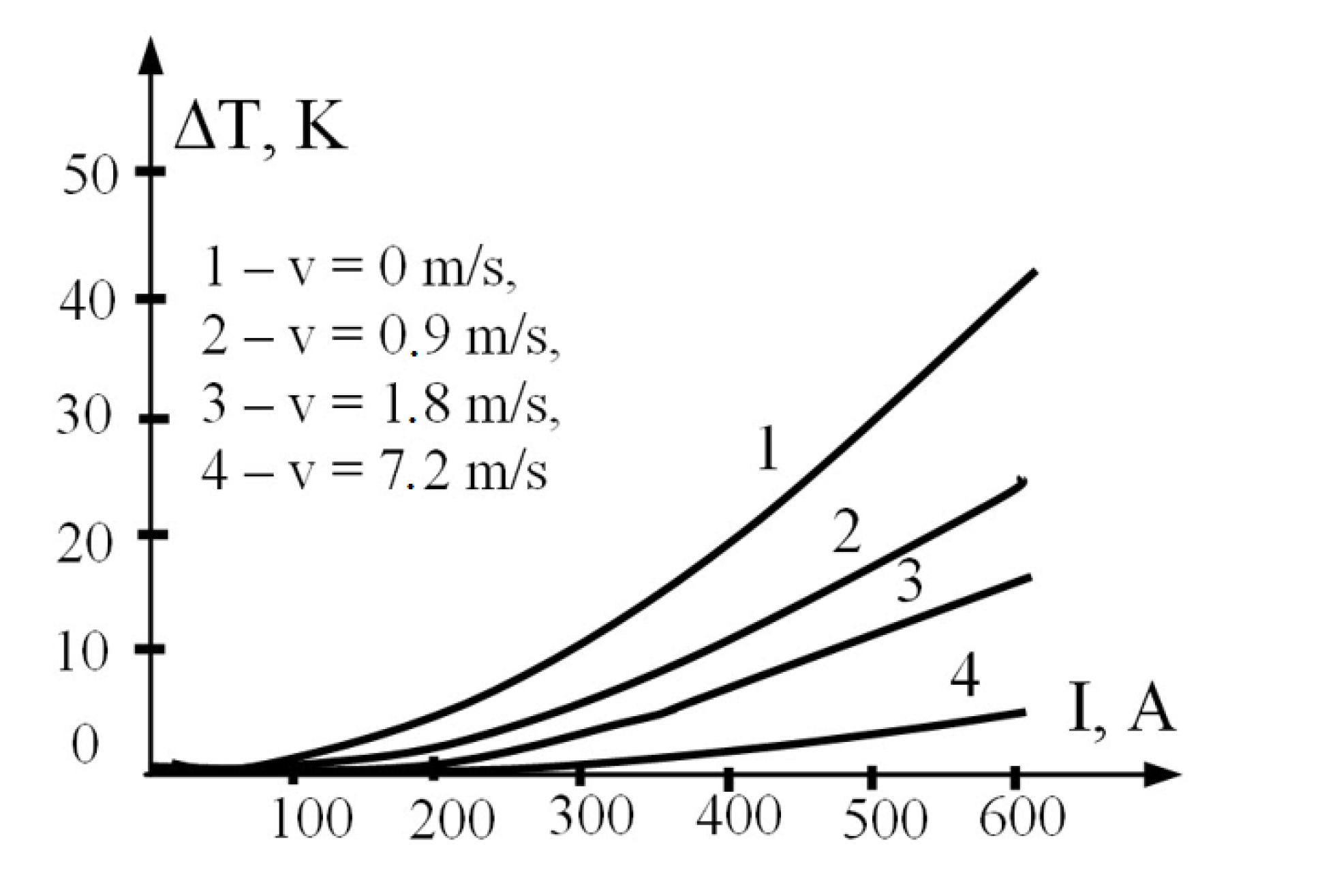
Figure 3.
Thermogram showing mid-phase superheating.
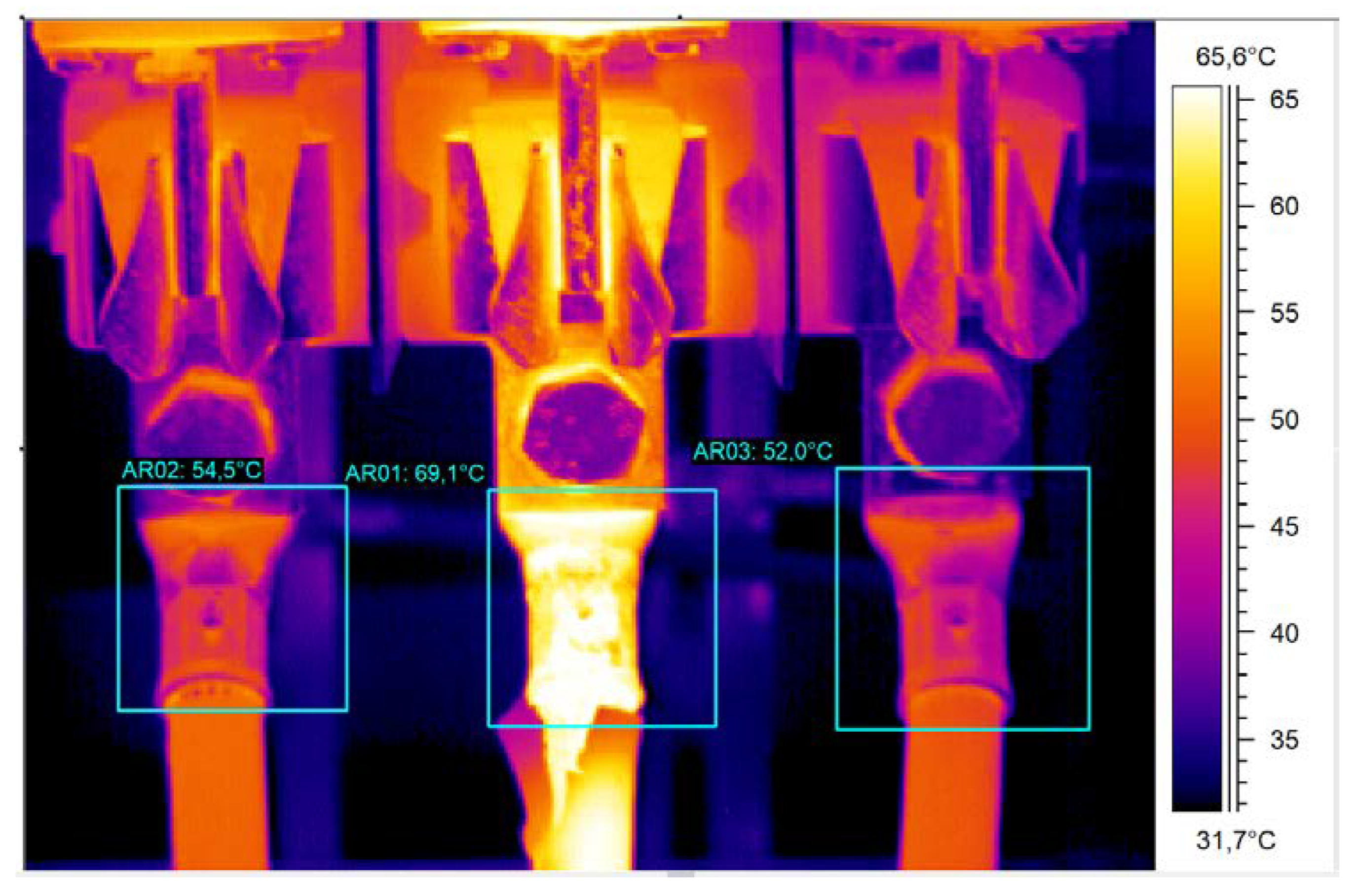
Table 1.
Assessment of the need to repair clamps (contact or connection) and power line conductors [17]. abbreviations: IMM - immediately, UR – urgently.
Table 1.
Assessment of the need to repair clamps (contact or connection) and power line conductors [17]. abbreviations: IMM - immediately, UR – urgently.
| Line load in % of nominal load | Assessing the condition of a component for need of replacement or repair | |||||||
|---|---|---|---|---|---|---|---|---|
| Wind speed < 2 m/s | Wind speed > 2 m/s | |||||||
| 10 - 30 K | 31 - 50 K | 51 - 70 K | > 70 K | 10 - 20 K | 21 - 35 K | 36 - 50 K | > 50 K | |
| 40 - 60 | UR | IMM | IMM | IMM | UR | IMM | IMM | IMM |
| 60 - 80 | UR | IMM | IMM | IMM | UR | IMM | IMM | IMM |
| > 80 | UR | UR | UR | IMM | UR | UR | UR | IMM |
Table 2.
Assessment of the need to repair the clamps and conditions of a low-voltage installation based on the calculation of the temperature rise ΔTn for the nominal load In [18]. abbreviations: IMM - immediately, UR - urgently, O – observe
Table 2.
Assessment of the need to repair the clamps and conditions of a low-voltage installation based on the calculation of the temperature rise ΔTn for the nominal load In [18]. abbreviations: IMM - immediately, UR - urgently, O – observe
| Fault class | ΔTn, K | Recommendations |
|---|---|---|
| 1 | > 30 | IMM |
| 2 | 5 – 30 | UR |
| 3 | < 5 | O |
Table 4.
Suggested actions suggested by the American National Standards Institute based on temperature rise [22].
Table 4.
Suggested actions suggested by the American National Standards Institute based on temperature rise [22].
| Temperature difference ΔT based on comparisons between similar components under similar loading | Temperature difference ΔT based upon comparisons between component and ambient air temperatures | Recommended action |
|---|---|---|
| 1 - 3 K | 1 - 10 K | Possible deficiency, warrants investigation |
| 4 - 15 K | 11 - 20 K | Indicates probable deficiency, repair as time permits |
| - | 21 - 40 K | Monitor until corrective measures can be accomplished |
| > 15 K | > 40 K | Major discrepancy, repair immediately |
Table 5.
Interpretation of the anomalies obtained from thermal imaging measurements according to the works [20,23].
| Fault class | Temperature rise ΔT, K | Recommended action |
|---|---|---|
| 1 | 0 < ΔT < 10 K | There is no need to take any action, but observe |
| 2 | 10 < ΔT < 35 K | Eliminate the weak point at the next shutdown - rectify if possible |
| 3 | 35 K < ΔT < 70 K | Eliminate of the weak point during the next planned maintenance, but within maximum 6 months |
| 4 | ΔT > 70 K | Immediate eliminate of a weak point |
Disclaimer/Publisher’s Note: The statements, opinions and data contained in all publications are solely those of the individual author(s) and contributor(s) and not of MDPI and/or the editor(s). MDPI and/or the editor(s) disclaim responsibility for any injury to people or property resulting from any ideas, methods, instructions or products referred to in the content. |
© 2024 by the authors. Licensee MDPI, Basel, Switzerland. This article is an open access article distributed under the terms and conditions of the Creative Commons Attribution (CC BY) license (http://creativecommons.org/licenses/by/4.0/).
Copyright: This open access article is published under a Creative Commons CC BY 4.0 license, which permit the free download, distribution, and reuse, provided that the author and preprint are cited in any reuse.


