
Submitted:
26 April 2024
Posted:
26 April 2024
You are already at the latest version
Abstract
In this study, the NiCrAlY coating was prepared using the atmospheric plasma spraying (APS). The sample was then exposed to a continuous fiber laser beam. Laser surface melting (LSM) can effectively homogenize the composition of the coating. It also reduced the defects and roughness. The coating was examined using optical microscopy (OM), scanning electron microscopy (SEM), and X-ray diffraction (XRD) analysis. The process parameters of the LSM consist of laser power and scan rate. The high-temperature oxidation test was conducted for 200 hours at a temperature of 1100 °C. After a period of 200 hours, the primary coating demonstrated the emergence of an aluminum oxide layer, along with the presence of harmful spinel oxides. The laser remelting technique was used to modify the surface, which led to the uniform growth and development of an aluminum oxide layer (α-Al₂O₃) during the oxidation examination. Therefore, it appears that the reduction in grain size caused by laser remelting prevents the wrinkling of Al2O3 oxide. This process represents a novel and alternative approach to modifying MCrAlY coatings.
Keywords:
Laser surface melting
; Surface modification
; NiCrAlY
; oxidation
1. Introduction
MCrAlY coatings were developed for the purpose of protecting the hot section of gas turbine engines [1,2]. These coatings use the symbol “M” to represent either nickel (Ni), cobalt (Co), or a combination of both elements [3]. This coating serves to minimize the occurrence of thermal expansion between the substrate and the ceramic layer, thereby reducing the potential for damage or delamination. The NiCrAlY coating consists of Ni as the carrier matrix, Cr for corrosion resistance at high temperatures, Al for governing the oxidation process, and Y for enhancing mechanical properties and promoting adhesion of the thermal-grown oxide layer (TGO) [4,5]. Thermal-grown oxide is formed when the thermodynamic growth rate of MCrAlY is reduced [6]. This oxide provides protection against high-temperature oxidation for alloys. The functionality of oxides is influenced by their composition, production techniques, and the surrounding environment. The γ and β phases play crucial roles in the coating’s properties. Specifically, the γ phase contributes to the enhancement of toughness and improvement of resistance to thermal fatigue. The β phase is a brittle source of aluminum supply. The growth of TGO is influenced by various oxidation conditions, including temperature and the partial pressure of oxygen. Furthermore, surface conditions play a significant role, encompassing factors such as surface chemical composition and surface roughness, among others [7,8,9]. Additionally, the microstructure of the material, including crystallographic defects and grain size, also plays a crucial role in TGO growth. The surface roughness of MCrAlY coatings has the potential to influence both the thermally grown oxide phase and the overall durability of the thermal barrier coating (TBC). Roughness is a fundamental characteristic of APS coatings. Roughness causes surface unevenness (convex and concave area) in the coating. The rapid growth in the convex region leads to the formation of brittle external spinel (Ni, Co) (Cr, Al)2O4 and α-Al2O3 [10,11]. In addition, Y-Al oxides are included in the convex region. These oxides can provide short-circuited ways for the transport of oxygen inside. As a result, the rate of growth is accelerated locally. The Y and Al reduction rate is dependent on Sa. Thus, it can lead to accelerating the rate of growth. The morphology of the TGO changes with variations in the roughness profile. The distribution of Y-Al oxide within the TGO layer hinders the diffusion of cation’s along the grain boundaries. As a result, the high-temperature oxidation resistance of the MCrAlY coating is enhanced [12,15]. The atmospheric plasma spray technique is employed for the production of monolithic metal coatings and thermal barrier coatings.
Remelting has been found to effectively enhance the high-temperature oxidation resistance of the MCrAlY coating [16,17]. After irradiation, Al2O3 oxides are formed on the remelted layer. The dimensions of these oxides are on the nanoscale. The creep strain of the oxide layer has an inverse relationship with the grain size. Therefore, remelting prevents the deformation and wrinkling of the oxide layer [18]. The femtosecond laser polishing technique, with a high pulse frequency, can effectively reduce surface roughness. It is possible to achieve the desired level of roughness by precisely controlling the timing and laser power [15]. The research has shown that oxidation of remelting coating by pulsed electron beam method includes a transition stage and a steady state stage [18].
The effect of laser remelting on the high-temperature oxidation resistance of NiCrAlY-APS coatings has been investigated in several studies. Laser surface modification has been found to improve the coatings’ surface performance and increase their resistance to hot corrosion and calcium-magnesium aluminosilicate (CMAS) attack [19]. Laser cladding of IN718 on Cr5Mo substrate has shown positive effects on the high-temperature oxidation resistance, with the eutectic quantity precipitation being positively correlated with the mass gain of the coating [20]. Electro spark deposition of NiCrAlY coatings on NiCrAlY alloy substrates has also demonstrated improved high-temperature oxidation resistance [21]. Laser cladding of NiCoCrAlYSi coatings on nickel-based high-temperature alloys, followed by high current pulsed electron beam (HCPEB) treatment, has resulted in a rather stable, continuous, and slow-growing α-Al2O3 layer on the surface, effectively reducing the growth rate and thickness of the thermally grown oxide (TGO) [22]. Laser remelting of high-velocity arc-sprayed FeNiCrBSiNbW amorphous coatings can significantly impact their microstructure and corrosion behavior. Studies have shown that laser remelting can lead to the recrystallization of the structure, resulting in increased hardness and improved tribological properties. [24]. Laser remelting on H13 steel enhances surface hardness through grain refinement, dislocation, and precipitation strengthening mechanisms, improving mechanical properties for mass production of hardened steel molds [25]. Laser remelting of WC-CoCr/HVOF coatings enhances microstructure, hardness, and wear resistance. Low energy density promotes W2C and Co3W3C formation, while high energy density leads to fragile phases and reduced performance [26]. Laser re-melting improved microstructural properties, resulting in a more stable microstructure for high entropy alloys. Laser re-melted HEAs showed lower oxide layer thickness, growth rates, and inner oxide formation after oxidation tests, indicating enhanced oxidation performance. CCrFeNiAl0.5 alloy exhibited the best oxidation performance due to the presence of Al-rich phases enabling the formation of an alumina layer on the surface [27]. High-current pulsed electron beam irradiation improved the oxidation resistance of the NiCrAlY bond coat, resulting in a smoother surface and a 3–5 μm thick remelting layer. The irradiation led to a decrease in the thickness of the thermal growth oxide layer, significantly enhancing the oxidation resistance of the bond coat. The main oxidation product observed after the treatment was Al2O3 [28]. Laser remelting treatment improved the compactness of the MCrAlY coating, eliminating defects like pores and inclusions. The highest laser power and scanning speed for complete melting is 385 w and 4 mm/s. The hot corrosion behavior of the TiAl alloy was significantly enhanced by the plasma-sprayed MCrAlY coating, further improved after laser remelting. Main corrosion products generated during hot corrosion included Al2O3, Cr2O3, NiO, NiCr2O4, Ni3S2, and CrS. Internal sulfurization reaction was found to not be beneficial for the improvement of the heat-resistant corrosion property of the coating [29]. The laser remelting treatment significantly improved the micro hardness and wear resistance of the Al85Ni8Y4Ce3 amorphous coating. The remelting process led to the formation of a crystalline structure in the coating, enhancing its mechanical properties [30].
In the present study, APS-NiCrAlY coating was chosen as the target material. The surface of the coating was modified through the utilization of a continuous fiber laser (CLSM). The parameters were chosen based on specific criteria, which included surface roughness, depth of the melted layer, and reduction of wastage of aluminum oxide and yttria. Following this, an investigation and analysis were conducted on the high temperature oxidation behavior of the coating, both prior to and subsequent to the CLSM process.
2. Methodology
According to the tests, the type of substrate is different. For the high-temperature oxidation test, Hastelloy X was applied to act a substrate. The substrate’ chemical composition is presented in Table 1. The 420 stainless steel was employed for the purpose of measuring thickness, roughness, and studying microstructure.. The substrate was then sandblasted to remove dirt and make it rough before spraying. Atmospheric plasma spraying machine was used for coating. MCrAlY powder with Ni-22Cr-11Al-1Y composition having spherical granulation was also used as the raw material. The powder granulation distribution is between 46 and 81 µm. Figure 1 represents the electron microscopic image related to the considered powder. APS parameters are presented in Table 2. The surface of the NiCrAlY coating was melted by using a continuous fiber laser with the maximum power of 1 kW. The laser machine had a four-axis Computer Numerical Control (CNC). Laser surface melting with 50% overlap was applied to the coating [31].The LSM process was performed by changing two parameters: laser power and speed. The molten pool’s surface was protected using the argon gas. The process parameters of LSM are presented in Table 3. The coating’s properties were then subjected to evaluation by applying optical and electron microscopes. In this research study, to check the coating’s resistance against oxidation, the considered samples were then placed in a furnace at the temperature of 1100 degrees Celsius for different periods of 50, 100, 150, and 200 hours. The TGO layer’s thickness was then measured by using an electron and optical microscope. This thickness was considered as a measure against oxidation. To measure the thickness and depth of the melted layer, the ImageJ image analysis software was used. X-ray diffraction analysis (XRD) was studied with emphasis on the phases in the TGO layer using a Philips X’Pert-MPD device with Cu Kα beam (λ=0.15406nm) under 30kV voltage and 40mA current. Phase detection was also determined by applying the Xpert High Score software.
3. Results and Discussion
3.1. NiCrAlY-APS Coating
The NiCrAlY coating with the thickness of 250±10 μm was utilized on the Hastelloy X substrate. In this relation, Figure 2a,b represents the cross-sectional as well as surface morphology of the considered original coating of NiCrAlY-APS. The wave-shaped coating was composed of melted and unmelted particles. APS coating has porosity and oxide streaks. The coating’s surface roughness was measured as Ra=8.25 µm, Rq=16.25 µm, Rz=26.45 µm. In the APS method, the particles are melted in flight. Then due to passing through the cold zone of the plasma jet, they are solidified again. In the following, it is placed as unmelted particles in the microstructure of the coating [16]. Due to the high spraying temperature, the impact of the splats on the substrate during cooling creates stress in the coating and causes cracks and holes in the surface of the coating. During the oxidation process, oxygen enters the coating through pores and cavities. This could affect the performance of the coating.
3.2. Remelting
The LSM laser surface melting process led to the surface modification of the coating. Surface melting parameters are presented in Table 4. Laser melting of NiCrAlY-APS was evaluated as single-pass and multi-pass with 50% overlap. (Figure 3). In the LSM process, heat control is necessary to achieve a smooth surface. The laser power and scanning speed for achieving complete melting are 385 W and 8mm/s, respectively. The parameters G1508 and G1504 lack the necessary laser power to melt the entire coating (Figure 3g). Partial surface melting was observed in some places. As can be seen in Figure 3l, about 50%, and Figure 3m,n about 70% of the coating were melted. Surface holes were observed in Figure 3p. Holes and cracks were observed at low speed and high laser power. The reason for this is the gas release in the porous areas and elements’ movement. The elements Y and Al with low solubility tend to combine with oxygen. The formation energies of various oxides in the thermodynamic state are as follows:
The molten pool is protected by the argon gas during the LSM process. Oxygen is released in the porous areas. Irradiation of laser beam on the surface causes melting, evaporation, and temperature rise. The EDS results are shown in Table 5. The elements yttrium and aluminum undergo a reaction with the oxygen present in the coating.. The Y-Al deposit in Figure 3e moves from the center to the edge because of vapor pressure. This happens parallel to the laser beam’s direction on the coating’s surface. During multi-pass melting, Y-Al deposits were formed as a strip (Figure 3n). By reducing the laser scanning speed, Y-Al oxide was dispersed on the coating’s surface. These findings conform to the previous research done in this field [18]. Laser melting width is more sensitive to laser power. The rise of laser power increases the molten pool’s temperature. So, the molten pool’s width increases [26,32]. To check the depth of the melted layer, the coating’s cross-section was cut by a wire. With the increase of laser power, the melted layer’s depth was increased from 25 m to 244.88 m (Figure 4). With the rise of the energy density in the LSM process, the melted layer’s depth was raised. A smooth surface of the coating was created. The melted layer’s depth has a linear relationship in regard to the parameter of laser power. At higher laser powers, heat transfer and evaporation occurred in the molten pool. The laser power of 150W controls the consumption of aluminum and yttrium elements. At the150W constant laser power, the rise of the speed from 4 mm/s to 8 mm/s caused surface polishing of the sample. A very small thickness of the sample was melted. In the sample G1504, a homogeneous layer with the thickness of 25 µm was obtained. At the constant laser power of 257W, aluminum and yttrium wastage was prevented by raising the speed from 4 mm/s to 8 mm/s. The remelting layers are homogeneous and completely free of porosity. Increasing the laserpower in G3854 and G3858 samples had a great impact on the remelting layer’s depth.
X-ray analysis was used to check the formed phases. The XRD pattern of the main coating includes NiAl-β، γ-Ni and Ni3Al- γ’. The related characteristic diffraction peaks were (111), (200) and (220). During the LSM process, the NiAl-β phase underwent a transformation into γ-Ni and Ni3Al-γ’ as a result of the release of aluminum elements in the background.. The peaks of γ-Ni and Ni3Al- γ’ were sharpened, which indicates the optimal grain orientation after the LSM process.. Investigations showed that the (111) and (220) peaks moved to lower angles, while the (200) peak moved to a higher angle.. It seems, therefore, that remelting and residual stress were the causes of angle change. Surface melting caused the excessive loss of aluminum and yttrium elements (Figure 5a). In the LSM process, input heat control is significant. The consumption of aluminum, yttrium, and peak intensity was increased in the sample G2574. As a result, Y-Al oxide was formed. In the sample G2578, the duration of the interaction of the laser beam with the surface was increased. Increasing the speed prevented the loss of the aluminum element. The XRD analysis showed two main phases in the coating and the samples G1504, G1508, and G2578. The phases were γ-Ni and Ni3Al- γ’. The XRD results also showed the presence of Ni، Ni3Al، Al2O3، Al5Y3O12, and Y2O3 phases in G2574, G3854 and G3858 samples. The increased heat in these samples caused aluminum and yttrium to be lost. It is, therefore, necessary to control the input heat (Laser power) to control the depth of the melted layer and focus on preventing the aluminum element’s loss and the formation of the NiAl-β phase Controlling the interaction of the laser beam with the surface is accomplished by changing the speed. Changing the laser power leads to the sharpening of the peaks. Research has shown that laser scanning speed does not affect the coating’s composition. The laser power change has resulted in sharper peaks and a more favorable grain orientation [14]. Thus, G1504, G1508 and G2578 parameters were used to check the oxidation test.
3.3. Surface Roughness
Roughness is an essential parameter for the coatings’ oxidation resistance. Roughness at the interface between TGO and metal coating leads to the destruction of the MCrAlY coating [17]. The main cover has a rough surface. The coating’s surface roughness after the LSM process was calculated to be Ra = 1.321 m, Rq = 1.5 m, and Rz = 1.6 m. Increasing the laser power from 150w to 385w could decrease roughness of the coating (Figure 6). The smoothness decreases when molten materials flow due to surface tension and gravity. [11]. The surface structure was changed by irradiating the laser beam to the coating surface. The layer obtained at low laser powers was free of pores.. Research has shown that reducing the surface roughness is a prerequisite for increasing the useful life of the MCrAlY coating and TBCs [24]. For the original coating with rough surfaces, oxidation occurs in the convex areas. After the LSM process, the oxide layer grows uniformly and slowly on the coating’s flat surface. The related results of the oxidation were further analyzed.
3.4. High-Temperature Oxidation Behavior
The related high-temperature oxidation behavior was evaluated before and after the LSM process at 1100 ℃ for 200. Figure 7 represents the XRD pattern of the coating prior to and following the LSM process. The original NiCrAlY coating underwent oxidation for 200 hours. This resulted in the formation of Cr2O3, and Ni(Cr,, and a small amount of . Meanwhile, after the LSM process, α-Al2O3 phase and garnet were formed. The TGO layer’s growth on the NiCrAlY coating surface involves three stages.
In the first step aluminum has a low Gibbs free energy, and the oxide Al2O3 is dominant over other oxides. Upon further heat exposure, γ- Al2O3 oxides are transformed into θ-Al2O3 oxides, and the rest are converted to α-Al2O3 oxides. The conversion of θ-Al2O3 to α-Al2O3 occurs in the second stage of oxidation. This process is referred to as transitional oxidation. Then, due to its preferred oxidation, aluminum tends to form a shell layer as a protective and stable oxide shell. At this stage, thermodynamically stable oxides grow. This stage is considered as the stable oxidation stage.
Observations showed that after 200 hours, an α-Al2O3 and spinel layer formed on the coating surface.. The layer formed on the coating was uneven and had varying thicknesses throughout. The average thickness of the TGO layer for the main coating was 4.20 µm. This study discovered that laser beam radiation improved the oxidation of NiCrAlY-APS coating. After 200 hours of oxidation, the LSM coating formed a protective layer of α- Al2O3. The monolayer that has been formed is continuous, dense, and possesses a uniform thickness.. The TGO monolayer is made up of Al2O3. It also has small areas with the mixed oxides (bright phases). The Y-Al oxides could be identified as YAG (Al3O5Y12) using EDS and XRD analysis. After 200 hours (at 1100 degrees Celsius), there is still no trace of a thick layer or mixed oxide islands (spinel). After 200 hours of oxidation, Y-rich particles are formed on the grain border of aluminum oxide. It, therefore, seems that the oxidation has entered a stable stage. Figure 8 shows the coating oxidation before and after the LSM process. A single oxide layer is formed in all coatings. In the NiCrAlY-APS core coating, there are gaps between the oxide layers. In the LSM sample, the oxides that are formed on the smooth coating’s surface are uniform and dense. Following 200 hours of oxidation, the EDS analysis revealed that the main coating had formed a layer. This layer is made up of two parts: an Al2O3 layer and a spinel one that contains Ni and Cr elements. Following the 200 hour oxidation, an aluminum oxide dense layer is formed on the smooth LSM coating. The LSM process reduced the Al2O3 anisotropic nucleation sites by reducing the height as well as width related to the considered coating. The grain size of the nucleation sites is a factor in the nucleation rate. This process decreased the aluminum oxide layer’ heterogeneous storage capacity, as compared to the original coating. These findings are the same as those obtained in the other research study [31,32,33,34].
Oxygen enters the coating through the grain boundaries of Al2O3. TGO growth rate is depends on rate at which oxygen anions are diffused into the coating. After the LSM process, a layer rich in Al2O3 is formed on the coating surface. This layer decreases the oxygen partial pressure at the interface between the coating and the TGO layer. As a result, it decreased the chance of oxygen reacting with other metal cations. The original coating’s rough surface made more oxygen ions be diffused into the TGO. Figure 9 represents the changes occurring in the TGO layer thickness following 200 h oxidation. The rougher the coating surface, the larger the surface area becomes. Consequently, the path of penetration increases significantly. The roughness of the main coating intensifies the penetration of aluminum, resulting in an increase in the thickness of the TGO layer during oxidation.
This investigation found that the TGO layer in the main coating was thicker than the LSM one. The oxygen activity at the interface of the main coating is high. This caused a brittle spinel phase to replace the protective aluminum oxide. This led to TGO layer separation and internal oxidation. Performing the LSM process decreased of grain size. This grain size reduction prevented the TGO layer from wrinkling. The parameters were selected in a manner to do the prevention of evaporation and the aluminum excess consumption. The laser remelting process has a high cooling rate. As a result, it creates more places for the formation of Al2O3. The performance of the Y element affects the growth of the TGO layer in the coating during the laser remelting process.. The laser melting process redistributed the Y element. It was in the form of Y-Al deposits on the coating surface. These deposits acted as oxide nails to improve the adhesion strength of TGO [14]. These deposits could also serve as suitable sites for the nucleation of α-Al2O3 oxide. Figure 10a displays Y-Al oxides which were present in the considered coating. These oxides act as non-penetrating nucleation sites and enhance the oxides nucleation.
These Y-Al oxides grain boundaries can serve as the short-circuit diffusion paths for Al ions. After the LSM process, the Al-Y deposits were enclosed in the remelting layer. Since the affinity of oxygen with Y outweighs that of Al, Y is diffused faster than Al when the oxygen pressure is high, and the considered temperature is the same [25,26]. Rapid oxidation of Y is inevitable when exposed to high- temperatures Thus, the rate of oxidation increases in the primary oxidation stage. The α-Al2O3 oxide in the LSM sample has a hexagonal structure. This structure prevents metal cations from getting to the surface. YAG particles are found in the grain boundaries of aluminum oxide, providing a path for oxygen anion to enter the coating. EDS analysis showed a series of oxides on the surface of both coatings (Figure 11a–c). Once α- Al2O3 oxide is formed and stabilized, the layer becomes thick. Meanwhile, the bright areas show spinel oxides. After the LSM process, the TGO layer is smoother than the oxide layer on the original coating surface. The results obtained from EDS analysis are also consistent with the XRD analysis. The oxide α- Al2O3 layer thickens over time. Y-rich particles were observed in α- Al2O3 oxide after 200 h of oxidation. Aluminum oxide relies on Y particles to stabilize scale adhesion [12]. Laser remelting made the grain size smaller to prevent the oxide shell from wrinkling. To summarize, selecting the correct parameters for remelting the coating is crucial. It helps to prevent the loss of Al and Y elements. After the LSM process, the coatings exhibited enhanced oxidation resistance owing to the reduction in surface roughness. As a result, the microstructure was reconstructed and the Y element was redistributed.
5. Conclusion
The APS process creates a metal coating porous with oxide streaks. Porosity is the right way for oxygen to penetrate into this coating. The aluminum in these coatings helps to create a protective oxide layer. The TGO layer plays a crucial role in providing protection. The penetration of oxygen causes the consumption of aluminum. Depletion of aluminum from the coating results in the heterogeneous and substantial growth of spinel and NiO on the Al2O3 layer, leading to the heterogeneous and accelerated growth of the TGO. The laser beam interacts with the coating surface and controls the incoming heat. This reduces surface roughness. The LSM process reduces roughness to avoid excessive aluminum consumption in rough areas. Laser remelting resulted in a dense and uniform TGO layer on the coating surface. This layer prevents the penetration of oxygen and other elements. The process caused slow growth and protected against oxidation for 200 hours. Original coating had a much higher growth rate. It also had bonding of the mixed oxides and internal oxidation.. Remelting helps increase surface area by reducing roughness and prevents excessive shrinkage by controlling the growth of Al2O3 and the presence of YAG particles. The results showed that performing the LSM process increased high-temperature oxidation resistance in NiCrAlY-APS coatings.Controlling parameters effectively mitigate the occurrence of excessive heat accumulation, thereby enhancing surface quality by minimizing defects and reducing roughness. Consequently, the utilization of this approach has significantly broadened the scope of fiber laser implementation in surface modification of coatings and the enhancement of turbine component longevity.
References
- Padture, N.P. Advanced structural ceramics in aerospace propulsion. Nat. Mater. 2016, 15, 804–809. [Google Scholar] [CrossRef] [PubMed]
- Clarke, D.R.; Oechsner, M.; Padture, N.P. Thermal-barrier coatings for more efficient gas-turbine engines. MRS Bull. 2012, 37, 891–898. [Google Scholar] [CrossRef]
- Brandl, W.; Grabke, H.; Toma, D.; Krüger, J. The oxidation behaviour of sprayed MCrAlY coatings. Surf. Coatings Technol. 1996, 86-87, 41–47. [Google Scholar] [CrossRef]
- Evans, A.G.; Mumm, D.R.; Hutchinson, J.W.; Meier, G.H.; Pettit, F.S. Mechanisms controlling the durability of thermal barrier coatings. Prog. Mater. Sci. 2001, 46, 505–553. [Google Scholar] [CrossRef]
- Ghadami, F.; Aghdam, A.S.R.; Ghadami, S. Microstructural characteristics and oxidation behavior of the modified MCrAlX coatings: A critical review. Vacuum 2020, 185, 109980. [Google Scholar] [CrossRef]
- Nijdam, T.J.; Kwakernaak, C.; Sloof, W.G. The effects of alloy microstructure refinement on the short-term thermal oxidation of NiCoCrAlY alloys. Met. Mater. Trans. A 2006, 37, 683–693. [Google Scholar] [CrossRef]
- Gil, A.; Shemet, V.; Vassen, R.; Subanovic, M.; Toscano, J.; Naumenko, D.; Singheiser, L.; Quadakkers, W. Effect of surface condition on the oxidation behaviour of MCrAlY coatings. Surf. Coatings Technol. 2006, 201, 3824–3828. [Google Scholar] [CrossRef]
- Zakeri, A.; Bahmani, E.; Aghdam, A.S.; Saeedi, B. A comparative study on the microstructure evolution of conventional and nanostructured MCrAlY powders at high-temperature. Surface and Coatings Technology 2020, 389, 125629. [Google Scholar] [CrossRef]
- Chen, Y.; Zhao, X.; Xiao, P. Effect of microstructure on early oxidation of MCrAlY coatings. Acta Materialia 2018, 159, 150–162. [Google Scholar] [CrossRef]
- Golightly, F.A.; Stott, F.H.; Wood, G.C. The influence of yttrium additions on the oxide-scale adhesion to an iron-chromium-aluminum alloy. Oxid. Met. 1976, 10, 163–187. [Google Scholar] [CrossRef]
- Qian, W.; Cai, J.; Xin, Z.; Ye, Y.; Dai, F.; Hua, Y. Femtosecond laser polishing with high pulse frequency for improving performance of specialised aerospace material systems: MCrAlY coatings in thermal barrier coating system. Int. J. Mach. Tools Manuf. 2022, 182, 103954. [Google Scholar] [CrossRef]
- Huang, L.; Sun, X.; Guan, H.; Hu, Z. Improvement of the oxidation resistance of NiCrAlY coatings by the addition of rhenium. Surf. Coatings Technol. 2006, 201, 1421–1425. [Google Scholar] [CrossRef]
- Dragos, U.; Gabriela, M.; Waltraut, B.; Ioan, C. Improvement of the oxidation behaviour of electron beam remelted MCrAlY coatings. Solid State Sci. 2005, 7, 459–464. [Google Scholar] [CrossRef]
- Ansari, M.; Razavi, R.S.; Barekat, M. An empirical-statistical model for coaxial laser cladding of NiCrAlY powder on Inconel 738 superalloy. Opt. Laser Technol. 2016, 86, 136–144. [Google Scholar] [CrossRef]
- Cai, J.; Yao, Y.; Gao, C.; Lyu, P.; Meng, X.; Guan, Q.; Li, Y.; Han, Z. Comparison of microstructure and oxidation behavior of NiCoCrAlYSi laser cladding coating before and after high-current pulsed electron beam modification. J. Alloy. Compd. 2021, 881, 160651. [Google Scholar] [CrossRef]
- Feng, Y.; Dong, T.-S.; Li, G.-L.; Wang, R.; Zhao, X.-W.; Liu, Q. High temperature oxidation resistance and TGO growth mechanism of laser remelted thermal barrier coatings. J. Alloy. Compd. 2020, 828, 154266. [Google Scholar] [CrossRef]
- Saharkhiz, R.; Valefi, Z.; Mirjani, M.; Abdollahi, A.; Taghi-Ramezani, S. Effect of hydrogen and argon shrouding gas flow rate on high-temperature oxidation behavior of NiCrAlY coating by solid shielding shrouded plasma spray (SSPS). Surf. Coatings Technol. 2020, 394, 125818. [Google Scholar] [CrossRef]
- Tolpygo, V.K.; Clarke, D.R. Surface rumpling of a (Ni, Pt)Al bond coat induced by cyclic oxidation. Acta Mater. 2000, 48, 3283–3293. [Google Scholar] [CrossRef]
- Cai, J.; Li, C.; Yao, Y.; Lyu, P.; Guan, Q.; Li, Y.; Lu, J. Microstructural modifications and high-temperature oxidation resistance of arc ion plated NiCoCrAlYSiHf coating via high-current pulsed electron beam. Corros. Sci. 2021, 182, 109281. [Google Scholar] [CrossRef]
- Avcı, A.; Karabaş, M.; Eker, A.A.; Akman, E.; Aslan, C. Hot corrosion and CMAS degradation of laser-glazed YSZ coating with optimum parameter. Proc. Inst. Mech. Eng. Part L: J. Mater. Des. Appl. 2023, 237, 2322–2334. [Google Scholar] [CrossRef]
- Xu, Z.; Wang, F.; Peng, S.; Liu, W.; Guo, J. Effects of Process Parameters on Microstructure and High-Temperature Oxidation Resistance of Laser-Clad IN718 Coating on Cr5Mo Steel. Coatings 2023, 13, 197. [Google Scholar] [CrossRef]
- Huang, L.; Zhou, Z.; Yang, L.; Qiao, Y. The Oxidation Properties of a NiCrAlY Coating Fabricated by Arc Ion Plating. Coatings 2022, 13, 22. [Google Scholar] [CrossRef]
- Wang, R.Y.; Feng, X.L.; Yang, C.; Guo, C.A.; Zhang, J. High-temperature oxidation resistance of NiCrAlY columnar microcrystalline coating deposited by EDS. Chalcogenide Lett. 2022, 19, 285–299. [Google Scholar] [CrossRef]
- Buchtík, M.; Březina, M.; Mrňa, L.; Palán, M.; Filipenský, J.; Doležal, P.; Nečas, D.; Frýza, J.; Kajánek, D.; Wasserbauer, J.; et al. Effect of Laser Remelting of Fe-Based Thermally Sprayed Coating on AZ91 Magnesium Alloy on Its Structural and Tribological Properties. Coatings 2023, 13, 1033. [Google Scholar] [CrossRef]
- Xie, J.; Di, R.; Li, J.; Liu, Y.; Raoelison, R.N.; Rachik, M. Effect of laser scanning velocity on the microstructural changes and mechanical properties of the H13 steel part treated by laser surface remelting. InIOP Conference Series: Materials Science and Engineering 2023, 1274, 012012. [Google Scholar] [CrossRef]
- Castro, R.d.M.; Curi, E.I.M.; Inacio, L.F.F.; Rocha, A.d.S.; Pereira, M.; Silva, R.G.N.; Pereira, A.d.S.P. Laser remelting of WC-CoCr surface coated by HVOF: Effect on the tribological properties and energy efficiency. Surf. Coatings Technol. 2021, 427, 127841. [Google Scholar] [CrossRef]
- Doleker, K.M.; Erdogan, A.; Zeytin, S. Laser re-melting influence on isothermal oxidation behavior of electric current assisted sintered CoCrFeNi, CoCrFeNiAl0.5 and CoCrFeNiTi0.5Al0.5 high entropy alloys. Surf. Coatings Technol. 2020, 407, 126775. [Google Scholar] [CrossRef]
- Mei, X.; Zhang, X.; Zhang, L.; Li, N.; Zhang, P.; Guo, Y.; Koval, N.N. Enhancing the Oxidation Resistance of NiCrAlY Bond Coat by High-Current Pulsed Electron Beam Irradiation. Coatings 2021, 11, 912. [Google Scholar] [CrossRef]
- Wang, D.S. Effects of Laser Remelting on Microstructural Characteristics and Hot Corrosion Behavior of MСrAlY Coating Prepared by Plasma Spraying. Mater. Sci. Forum 2019, 971, 70–76. [Google Scholar] [CrossRef]
- Pei, C.G.; Guo, Z.X.; Xiao, J.G. Effect of laser remelting treatment on Al85Ni8Y4Ce3 amorphous coating. Surf. Eng. 2020, 37, 642–649. [Google Scholar] [CrossRef]
- Jahromi, M.G.; Razavi, R.S.; Valefi, Z.; Naderi-Samani, H.; Taghi-Ramezani, S. Evaluating laser surface melting of NiCrAlY-APS coating and its effect on high-temperature oxidation behavior of NiCrAlY/YSZ thermal barrier coating before and after surface melting. Heliyon 2023, 9, e23094. [Google Scholar] [CrossRef] [PubMed]
- Gil, A.; Shemet, V.; Vassen, R.; Subanovic, M.; Toscano, J.; Naumenko, D.; Singheiser, L.; Quadakkers, W. Effect of surface condition on the oxidation behaviour of MCrAlY coatings. Surf. Coatings Technol. 2006, 201, 3824–3828. [Google Scholar] [CrossRef]
- Yu, C.; Pu, W.; Li, S.; Bao, Z.; Cheng, R.; Jiang, C.; Liu, Z.; Zhang, W.; Zhang, L.; Zhao, S.; et al. High-temperature performance of Pt-modified Ni-20Co-28Cr-10Al-0.5Y coating: Formation mechanism of Pt-rich overlayer and its effect on thermally grown oxide failure. Surf. Coatings Technol. 2023, 461. [Google Scholar] [CrossRef]
- Zhang, C.; Cai, J.; Lv, P.; Zhang, Y.; Xia, H.; Guan, Q. Surface microstructure and properties of Cu-C powder metallurgical alloy induced by high-current pulsed electron beam. J. Alloy. Compd. 2017, 697, 96–103. [Google Scholar] [CrossRef]
Figure 1.
Electron microscopic image of NiCrAlY metal powder.
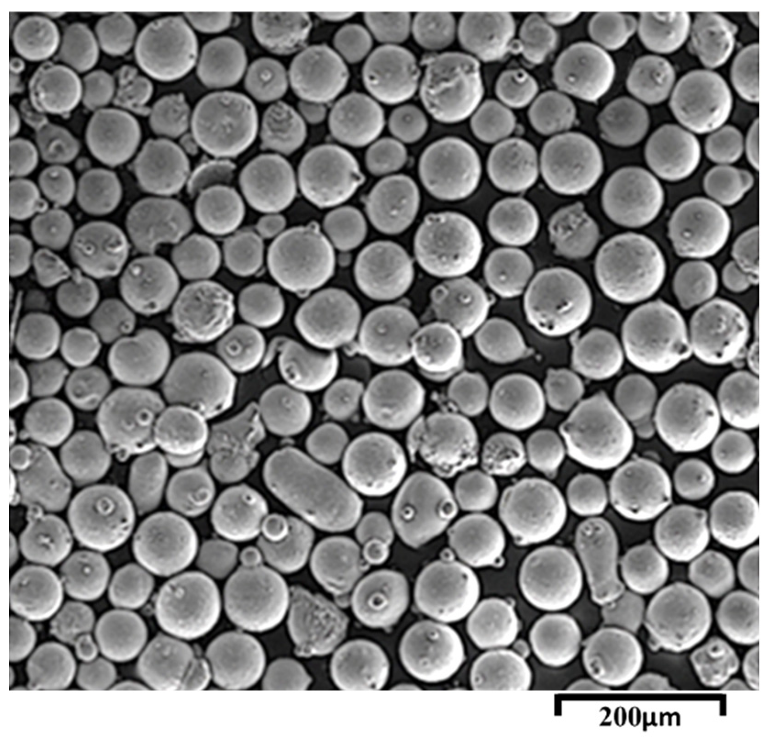
Figure 2.
(a) OM image of the cross section of the coating, and (b) SEM image of the NiCrAlY coating surface.
Figure 2.
(a) OM image of the cross section of the coating, and (b) SEM image of the NiCrAlY coating surface.
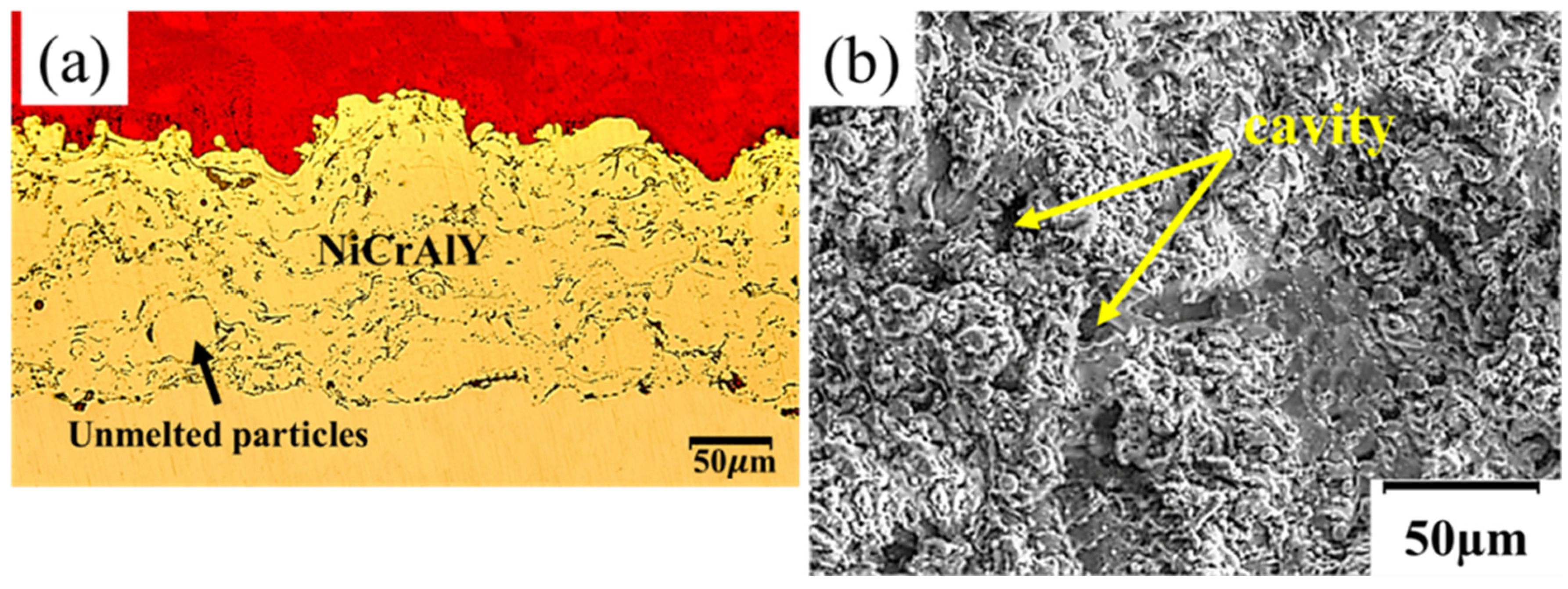
Figure 3.
SEM image related to (a) single-pass remelting and (b) multi-pass remelting.
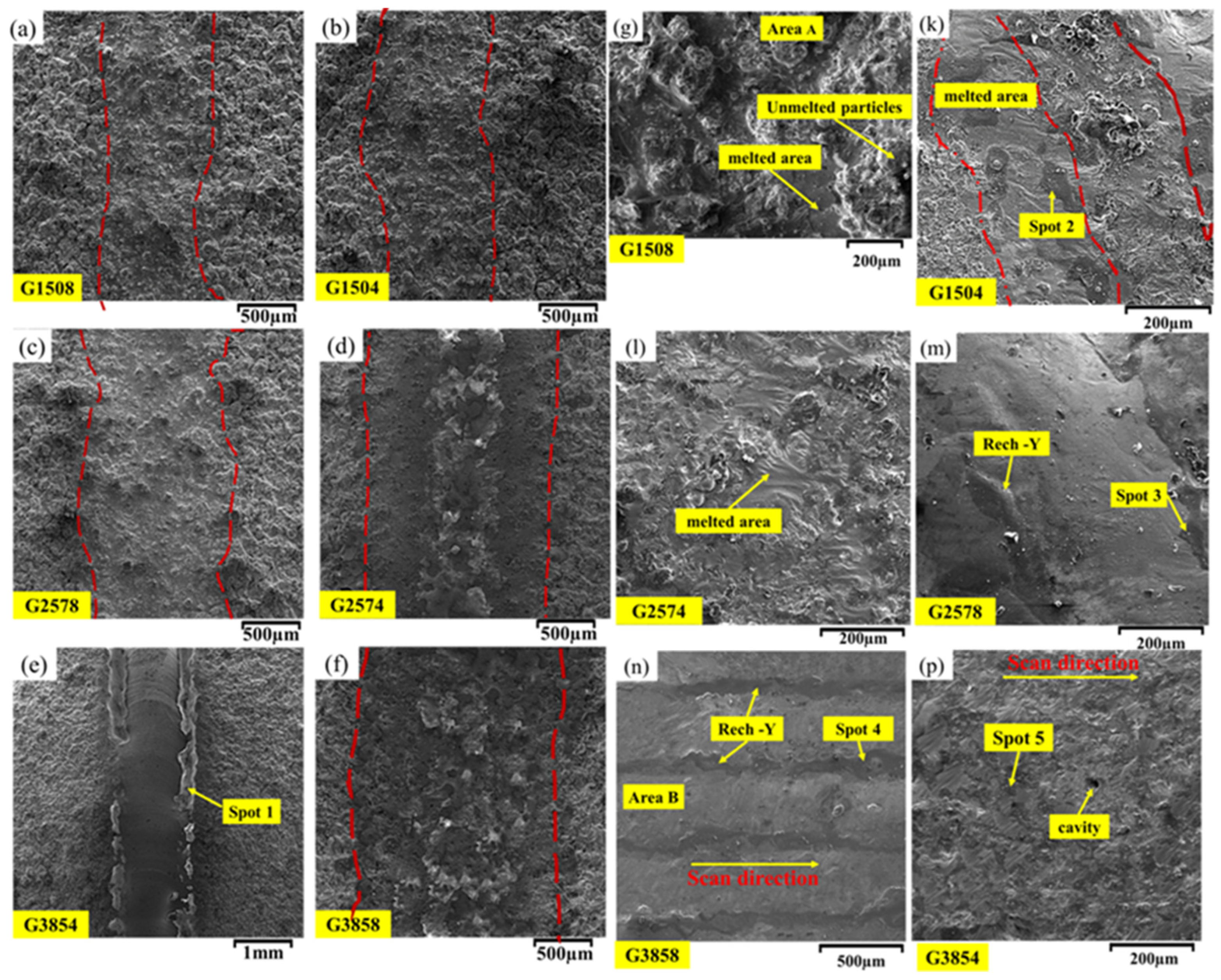
Figure 4.
(a–f) Cross-sectional morphologies of the coatings after remelting with different P0 and F0, and (g–h) the EDS map of a and e.
Figure 4.
(a–f) Cross-sectional morphologies of the coatings after remelting with different P0 and F0, and (g–h) the EDS map of a and e.
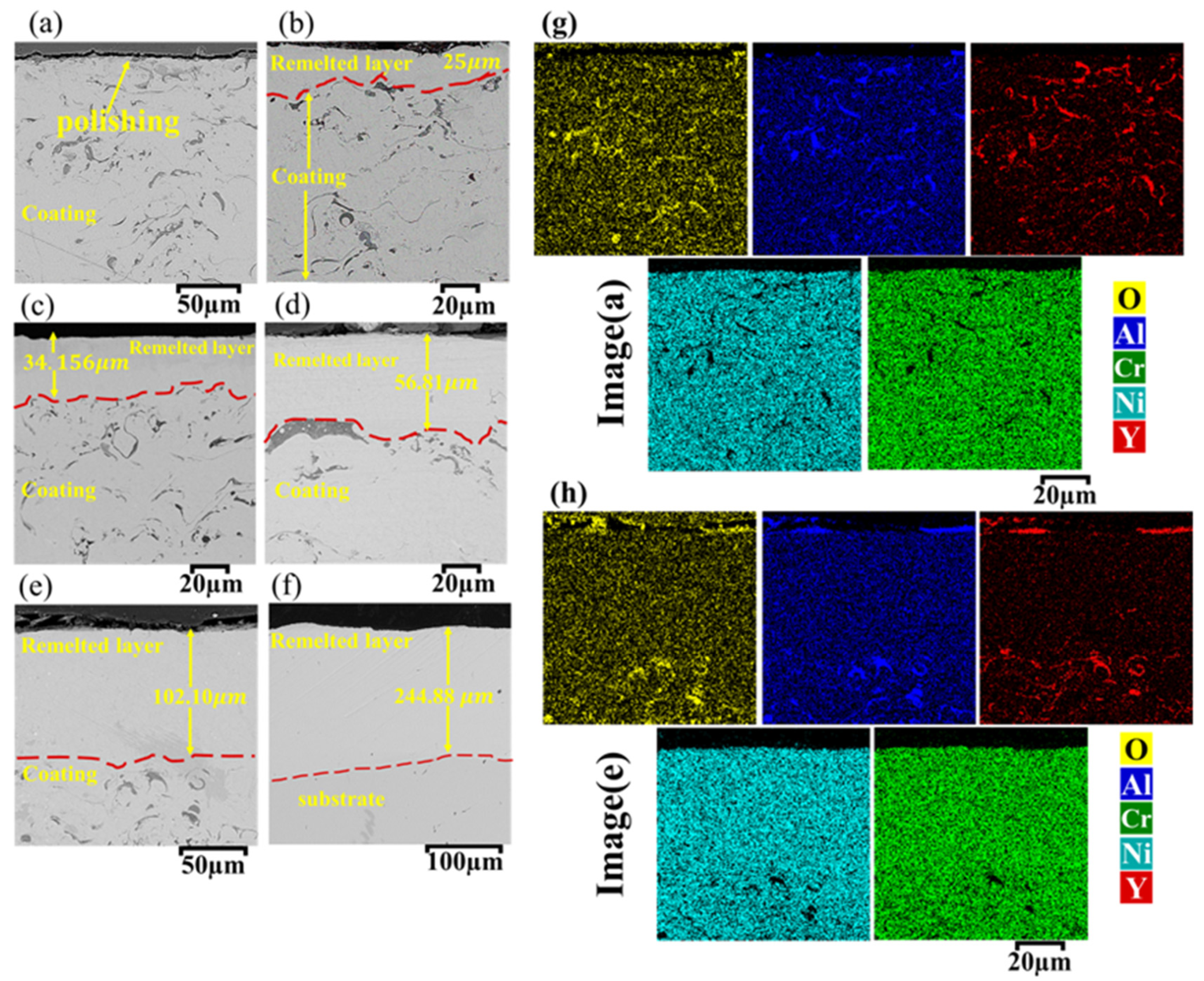
Figure 5.
X-ray pattern of the NiCrAlY coating before and after LSM process with different P0 and S0, (a) original coating and G2574, G3854 and G3858, (b,c) original coating and G2578, G1504 and G1508 parameters.
Figure 5.
X-ray pattern of the NiCrAlY coating before and after LSM process with different P0 and S0, (a) original coating and G2574, G3854 and G3858, (b,c) original coating and G2578, G1504 and G1508 parameters.
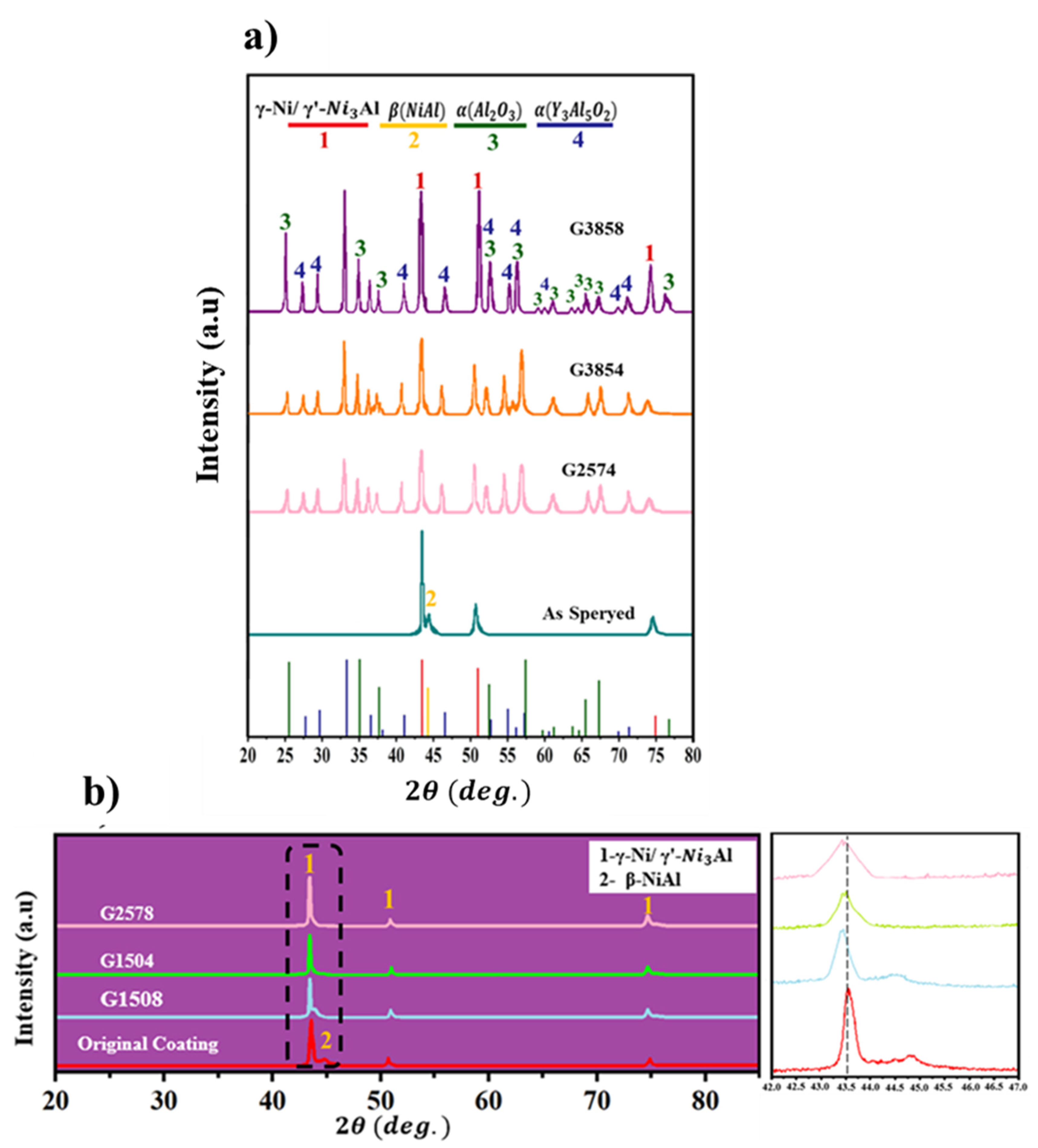
Figure 6.
The effect of different parameters (P0, F0) on the coating surface roughness.
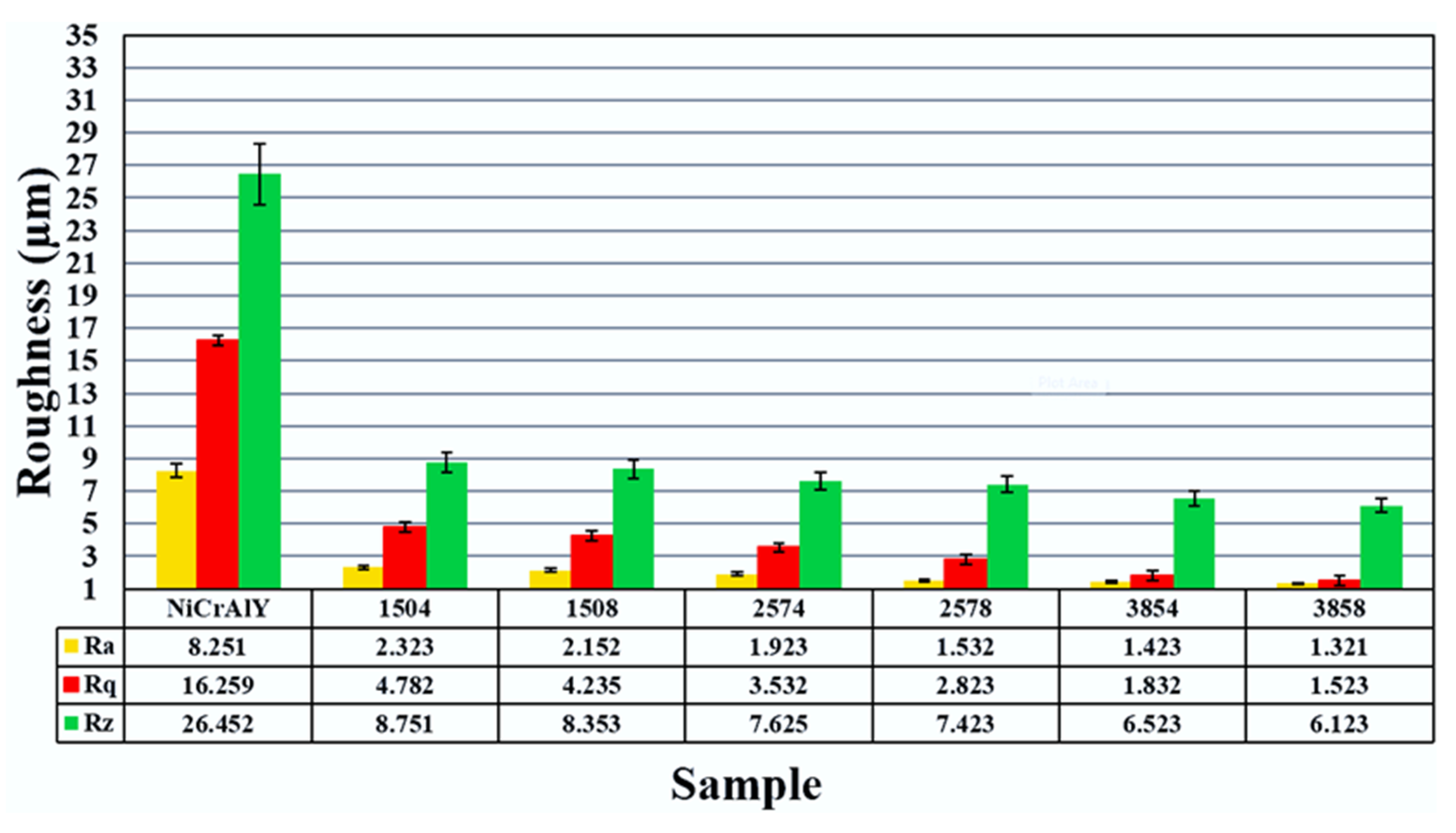
Figure 7.
XRD patterns of the NiCrAlY coating before and after the LSM process at 1100℃ for 200 hours.
Figure 7.
XRD patterns of the NiCrAlY coating before and after the LSM process at 1100℃ for 200 hours.
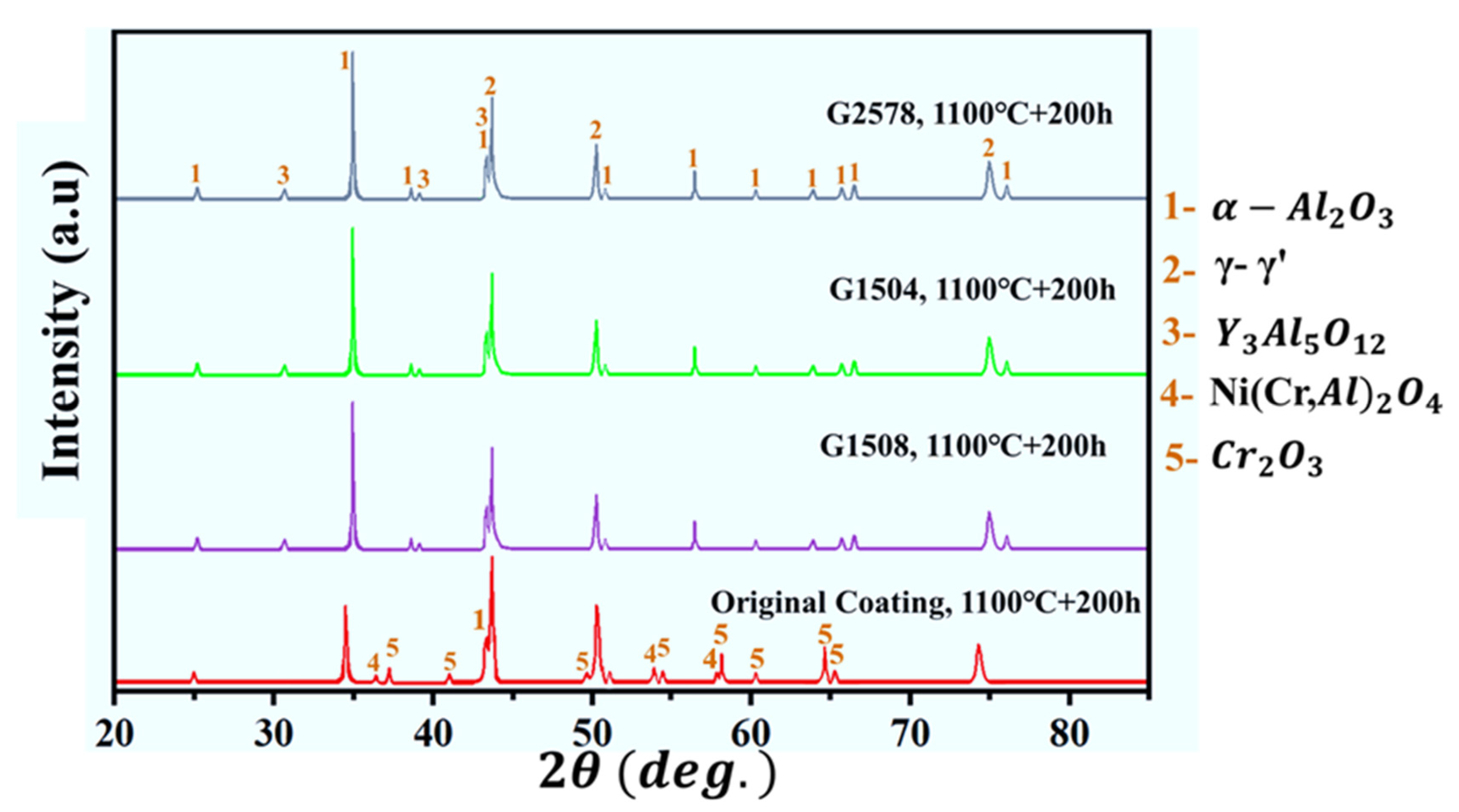
Figure 8.
Cross-sectional morphologies of NiCrAlY coatings following LSM with different parameters after 200 hours of oxidation at 1100 degrees Celsius, (a) original coating, (b) G1508, (c) 1504, (d) G2578, and (e) EDS analysis related to the points determined in (a–d).
Figure 8.
Cross-sectional morphologies of NiCrAlY coatings following LSM with different parameters after 200 hours of oxidation at 1100 degrees Celsius, (a) original coating, (b) G1508, (c) 1504, (d) G2578, and (e) EDS analysis related to the points determined in (a–d).
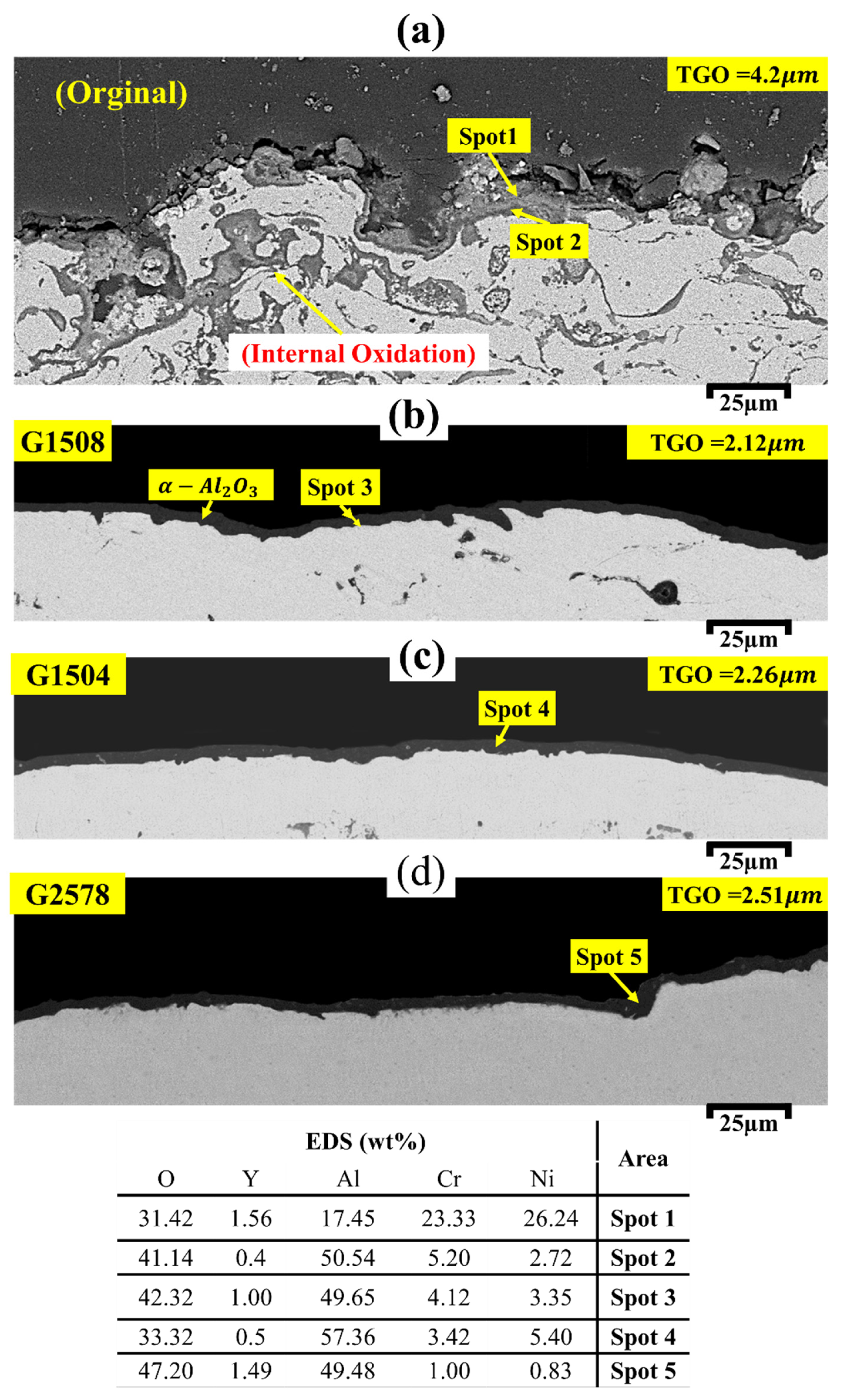
Figure 9.
Thickness of the TGO layer of the NiCrAlY coating before and after the LSM process.
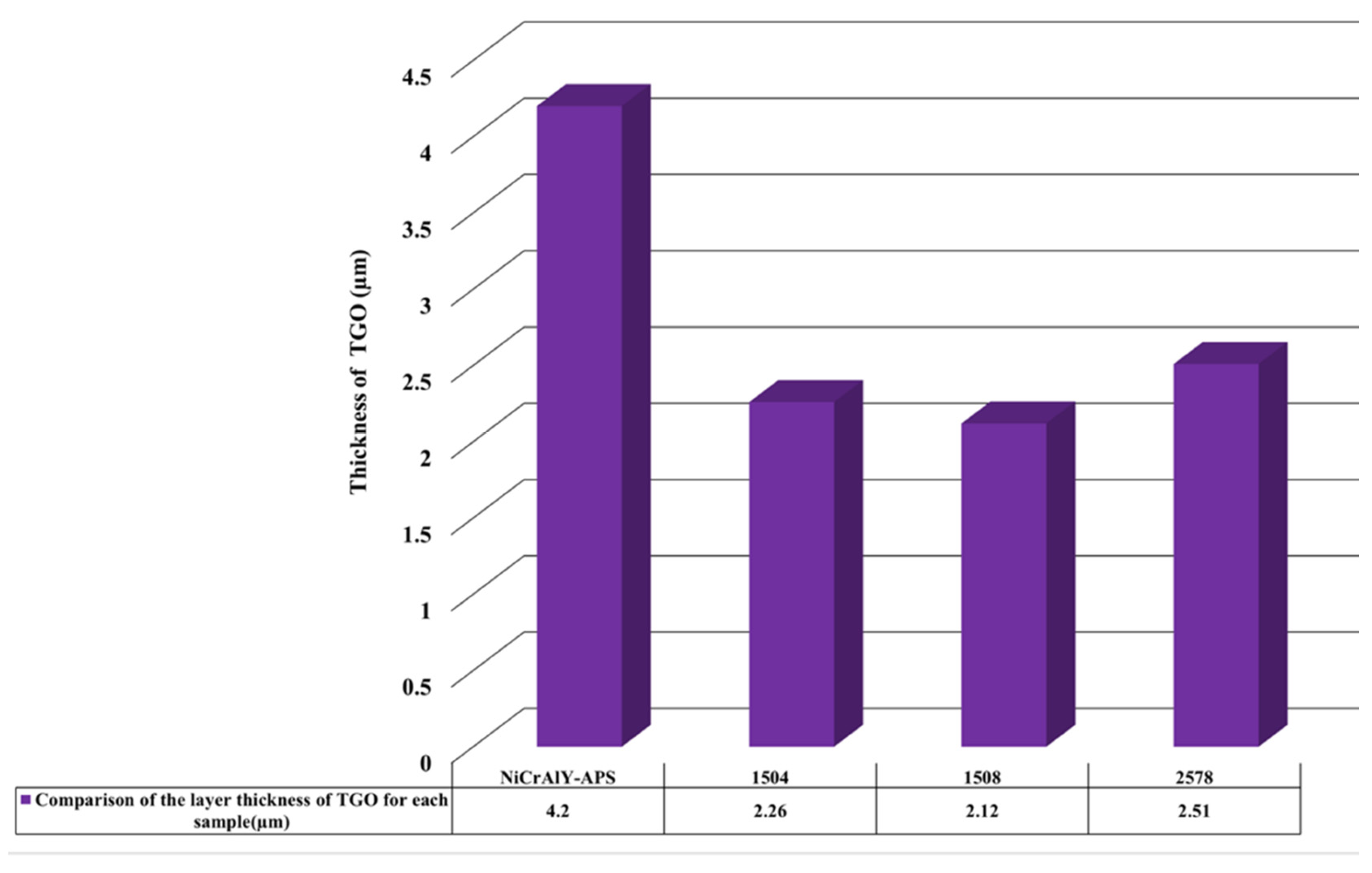
Figure 10.
SEM image at high magnification (a) G1504 and (b) original coating.
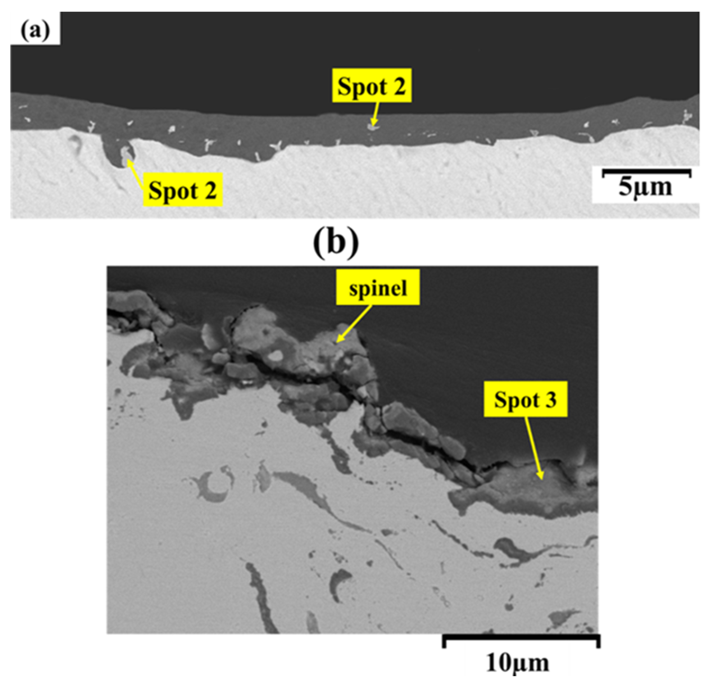
Figure 11.
The results of the EDS analysis related to the points determined in Figure 10.
Figure 11.
The results of the EDS analysis related to the points determined in Figure 10.
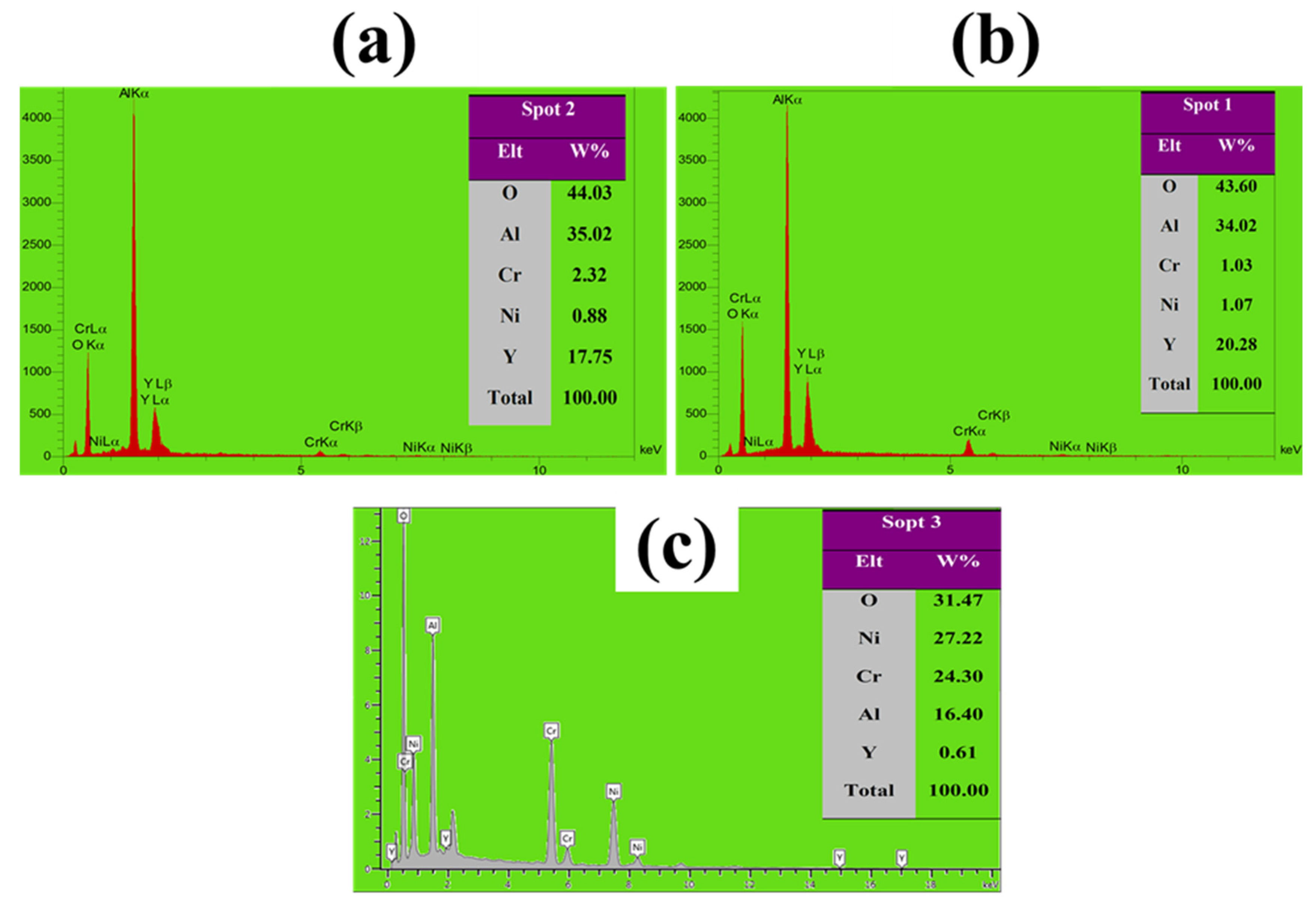

Table 1.
Chemical composition of the substrate.
| Ni | Cr | Fe | Mo | Co | W | Si | C | Mn | Al | S | Ti | B | element |
|---|---|---|---|---|---|---|---|---|---|---|---|---|---|
| 48.80 | 21.47 | 1 | 7.50 | 8.98 | 1.23 | 0.67 | 0.49 | 0.095 | 0.42 | 0.059 | 0.13 | 0.005 | Wt% |
Table 2.
APS process parameters in the NiCrAlY coating.
| NiCrAlY | Unit | Parameter |
|---|---|---|
| 550 | A | current |
| 75 | l/min | Argon gas flow rate |
| 11 | SLPM | Hydrogen gas flow rate |
| 2.5 | l/min | Powder carrier gas flow rate (argon) |
| 15 | g/min | Powder feed rate |
| 120 | mm | Spray distance |
Table 3.
LSM process parameters.
| Laser type | Continuous fiber |
|---|---|
| Wavelength (nm) | 1080 |
| Diameter of laser beam | 30 |
| Line distance | d1=d2=40 |
| Laser Power (w) | 150-257-385 |
| Scan speed (mm/s) | 4-8 |
Table 4.
Parameters used in the LSM process.
| Laser Power (W) | Scan speed (mm/s) |
|---|---|
| 150 | 4 |
| 257 | 4 |
| 385 | 4 |
| 150 | 8 |
| 257 | 8 |
| 385 | 8 |
Table 5.
The results of EDS analysis related to the points determined in Figure 3.
Table 5.
The results of EDS analysis related to the points determined in Figure 3.
| EDS (wt%) | Area | ||||
|---|---|---|---|---|---|
| O | Y | Al | Cr | Ni | |
| 5.7 | 0.48 | 14.32 | 20.9 | 58.6 | Area A |
| 4.3 | 0.84 | 10.3 | 24.26 | 60.3 | Area B |
| 52.64 | 9 | 37.33 | 0.38 | 0.65 | Spot 1 |
| 49.06 | 4.3 | 258.83 | 6.51 | 14.31 | Spot 2 |
| 25.80 | 12.56 | 22.90 | 11.13 | 27.61 | Spot 3 |
| 50.71 | 3.28 | 23.95 | 7.79 | 14.27 | Spot 4 |
| 40.60 | 22.90 | 34.16 | 1.27 | 1.07 | Spot 5 |
Disclaimer/Publisher’s Note: The statements, opinions and data contained in all publications are solely those of the individual author(s) and contributor(s) and not of MDPI and/or the editor(s). MDPI and/or the editor(s) disclaim responsibility for any injury to people or property resulting from any ideas, methods, instructions or products referred to in the content. |
© 2024 by the authors. Licensee MDPI, Basel, Switzerland. This article is an open access article distributed under the terms and conditions of the Creative Commons Attribution (CC BY) license (http://creativecommons.org/licenses/by/4.0/).
Copyright: This open access article is published under a Creative Commons CC BY 4.0 license, which permit the free download, distribution, and reuse, provided that the author and preprint are cited in any reuse.


