Submitted:
23 April 2024
Posted:
23 April 2024
You are already at the latest version
Abstract
To achieve rapid post-earthquake repair of self-centering ribbed floor flat beam frame structures, a ductile hybrid joint consisting of dog bone weakened energy dissipating steel bars connected to the upper and lower column sections through high-strength threads based on the damage control design concept is proposed. By moving the ductile energy dissipating zone out to the locally weakened section of the energy dissipating steel bars and the locally unbonded prestressed steel bars in the core area, the residual deformation was limited and the seismic performance was improved. Based on the working principle of hybrid joints, low cycle loading tests were conducted on two joint specimens to analyze the influence of lateral prestress on the seismic performance of the hybrid joints. Numerical modeling methods were used to compare the position of the energy-consuming steel bars in the composite layer and the friction performance of joints. The research results indicated that the hybrid joint had stable load-bearing, deformation, and energy dissipation capabilities, with damage primarily concentrated on the energy-consuming steel bars. Even at an inter-story displacement angle of 5.5%, the upper and lower column segments remained elastic. After unloading, the connection seam at the joint was closed, and the self-centering performance was good. When the inter-story displacement angle reached 5.5%, the lateral prestress increased from 150 kN to 250 kN, the ultimate bearing capacity of the joint increased by 16.3%, and the cumulative energy consumption increased by 30.0%. The influence of the friction coefficient of the joint surface on the structural performance was set at a threshold of 0.7. When it was less than the threshold, the ultimate bearing capacity and initial stiffness of the joint increased with an increase in the friction coefficient. After reaching the threshold, the increase in the ultimate bearing capacity of the joint slowed down, and the rate of stiffness degradation gradually accelerated. This joint had excellent seismic performance and can also achieve post-earthquake repair of structures.
Keywords:
Prestressed friction joint
; low frequency cyclic loading
; Energy dissipation performance
; Hybrid joint
; Low damage
1. Introduction
The self-centering ribbed floor flat beam frame structure was first created by the Institute for Testing of Materials Republic of Serbia and is abbreviated as the "Yugoslav plate (IMS) structural system." It has been widely adopted due to its excellent seismic resistance and construction speed. The current seismic design concept of "small earthquakes are not harmful, medium earthquakes are repairable, and large earthquakes are not collapsing" ensures the overall seismic energy dissipation capacity and collapse resistance of the structure by allowing plastic deformation of components or joints. These irreversible plastic residual deformations often have a serious impact on the normal use of a structure and require repair after an earthquake. However, the repair work not only hinders the normal operation of the building but sometimes even exceeds the cost of demolition and reconstruction.
The National Institutes of Standards and Technology (NIST) [1-5] research project and the Precast Seismic Structural Systems (PRESSS) program in the United States have proposed the use of prestressing technology to control residual deformation of prefabricated concrete structures while reducing damage to structural components by dissipating energy through joint energy dissipation systems. Morgen [6] designed and conducted experiments on setting friction damping energy dissipation devices at both ends of prestressed prefabricated beam column joints. The results indicated that pre-stressed prefabricated friction joints equipped with friction dampers had good energy dissipation performance. Huang Linjie[7-8] completed 14 sets of prestressed concrete frame joint tests with variable friction dampers (VFDs) placed in the joint area. The results showed that this type of joint had good load-bearing capacity and ductility while effectively solving the problems of high-order modal effects of self-centering structures, the reduced stiffness of joints after pressure reduction, and excessive inter-story lateral displacement. To solve the problem of the difficult installation of energy-consuming steel bars at the bottom of prefabricated beams with prestressed prefabricated joints, Guo Haishan [9-10] proposed an asymmetric reinforcement structure of precast prestressed efficiently fabricated frame (PPEFF) joints and conducted joint and overall frame tests. The research showed that the PPEFF system had a fast construction speed, low labor consumption, and excellent seismic and continuous collapse resistance performance. Wang Xianming [11]completed a quasi-static test of an IMS prestressed slab column interlayer model with four columns and two panels. The results showed that the frictional bending moment accounted for approximately 45% of the ultimate bending capacity of the joint.
Currently, there has been relatively little research on the impact of friction torque at the end of the IMS system composite beam on the seismic performance of joints, and there are problems with the insufficient energy consumption of joints and difficulty in repairing the seismic toughness of prefabricated components after earthquakes. To address the aforementioned issues, this article proposes a ductile hybrid joint based on the concept of damage control that is connected to the upper and lower column segments by high-strength threaded connections using dog bone weakened energy-dissipating steel bars. Based on the working principle of hybrid joints, low cycle loading tests are then conducted on two joint specimens, and numerical modeling methods are used to compare the position of the energy-consuming steel bars in the composite layer and the friction performance of the joints. The load-bearing, deformation, and energy dissipation capacity of the joints are studied in order to achieve rapid post-earthquake repair of a structure by replacing damaged energy-consuming steel bars and prestressed steel bars in the open channel for secondary tensioning.
2. Overview of Hybrid Joints
A hybrid joint with replaceable energy-consuming steel bars was constructed, as shown in Figure 1. Prefabricated columns and bi-directional ribbed floor slabs were assembled together using the post tensioning method to form a spatial frame structure with a laminated beam at the bottom, and the concrete in the core area of the joint was in a triaxial compression state. The difference between the lower prefabricated and upper cast-in-place composite beams of the prestressed prefabricated frame structures and the upper cast-in-place composite beams is that the IMS system composite beams are "sandwich" shaped (prefabricated at both ends and cast-in-place in the middle), and the vertical connection surface of the "sandwich" type composite beam is more conducive to bearing the bending moment at the beam end than the horizontal connection surface of the upper and lower composite beams. On the basis of utilizing the construction space provided by the open channel combined with the weakening method of the "dog bone" joint beam flange in steel structures, the designated ductile energy dissipation zone was moved outward to the local weakening section, and a hybrid connection prefabricated dense rib plate column joint was proposed.
As shown in Figure 2a, due to the channels on the corners of the IMS system floor slab and the double-sided flat connection with the columns, this connection method is different from the traditional single-sided flat connection of prefabricated beams and columns where the stress on the two faces of the corners is interrelated. For the IMS system of rectangular columns, the bending moment on one surface becomes the torque on another surface, and the torque in turn becomes the bending moment on another surface, which is the torsional moment generated by the frictional shear force. This torque is called the frictional torque at the end of the composite beam. The unique frictional torque at the end of the laminated beam in the IMS system joint can generate relative sliding friction energy dissipation through the plate column interface under large deformation, which has the same effect as the energy dissipation devices added outside the joint. The spatial deformation and force principle of the joint are shown in Figure 2b. The bending load at the end of the slab is transmitted to the joint of the slab and column through the edge ribs and the post poured open channel of the prefabricated slab. Under the action of earthquakes, the relative rotation between prefabricated columns and prefabricated slabs causes close contact on one side of the prefabricated slab and column, forming a rotation center. The open channel on the closer side undergoes slight compression deformation, while the open channel on the farther side undergoes significant elongation deformation, causing plastic damage to primarily concentrate on the contact section between the open channel and the prefabricated column. In response to the phenomenon of poor energy consumption in this type of joint, a hybrid connection structure of the energy-consuming steel bars and prestressed steel bars is proposed in the joint open channel. The setting of energy-consuming steel bars can significantly improve the energy consumption performance and post-earthquake repairability of the joint. Lateral prestressed and composite beams provide out of plane constraints to ensure sufficient and stable energy consumption capacity.
3. Experimental Overview
3.1. Test Piece Design
To study the seismic performance and functional recoverability of hybrid joints, two specimens with the same overall geometric dimensions were designed in the experiment, numbered A1 and A2. The overall dimensions of the specimens are shown in Figure 3a. The total height of the prefabricated column was 1600 mm, with a cross-sectional size of 360 mm × 360 mm. The concrete strength of the open channel and the composite layer was C40. The thickness of the protective layer of the specimen was 15 mm, the width of the open channel was 100 mm, the rib height of the prefabricated floor slab was 150 mm, and the thickness of the composite floor slab was 120 mm. The magnitude of the lateral prestress in the experimental design was used as a variable to study the influence of the frictional torque at the end of the composite beam on the seismic performance of the joint. A total initial prestress of 400 kN was applied to the longitudinal open channel prestressed reinforcement. The total initial prestress applied to the transverse open channel prestressed reinforcement was 150 kN and 250 kN, with a protective layer thickness of 15 mm. Holes were reserved inside the prefabricated column, and steel bar connectors were embedded. The research on the bearing capacity failure and failure mechanism of the cast-in-place beam slab column joints under earthquake action is relatively mature, so no comparative tests were conducted on the cast-in-place beam slab column joints.
The structure of the specimen joint is shown in Figure 3b. The longitudinal bars connecting the upper and lower portions of the composite beam to the column were locally weakened and treated without bonding. They were arranged in an open channel, and the longitudinal bars were connected to the pre-embedded steel bars in the column through a steel thread connector. The prestressed bars near the core area of the joint were changed from originally bonded to locally unbound. The prestressed steel strands were wrapped with double-layer polyethylene tape for local unbound treatment, and the length of the unbonded section was 500 mm. The length of the weakening section of the energy-consuming steel bar was 120 mm, and the proportion of the section weakening was 15%. The prefabricated components and prestressed steel bars were made of 1×7 Φ S15.2 steel strand with a steel strand strength of fptk = 1928 MPa and fpy = 1786 Mpa and designed according to current specifications [12]. The size structure and reinforcement are shown in Figure 4.
3.2. Material Properties
According to GB/T 228.1-2010[13] "Tensile testing of metallic materials - Part 1: Room temperature test method," samples were collected from the internal steel bars of various key components (all HRB400 grade), and material tensile tests were conducted. The mechanical performance indicators of the steel bars with different diameters are shown in Table 1.
The design strength grade of the precast concrete components was C40. At the same time as pouring each specimen, 150 mm × 150 mm × 150 mm cubic test blocks were constructed and cured under the same conditions as the components. The average compressive strength of the concrete cube measured during specimen loading was 41.0 MPa. To improve the early compressive strength and final flexural strength of the grouting material, a high-strength non shrinkage grouting material mixed with steel fibers was selected. The material properties are shown in Table 2.
3.3. Experimental Loading and Measurement Plan
3.3.1. Loading Device
The low cycle repeated loading test was conducted at the Engineering Structure Center of Hebei Agricultural University. The loading device is shown in Figure 5a, and it consisted of one 1000 kN vertical hydraulic jack, two 500 kN bidirectional CNC hydraulic jacks with ball joints, one set of ball joint column caps with horizontal pull rods, and a reaction frame. The hydraulic jack was connected to the loading point at the plate end using anchoring screws, steel clamps, and vertical hydraulic jacks to apply axial pressure to the top of the column, and these could freely slide along the horizontal direction with the specimen. To prevent out of plane overturning, rigid triangular supports were installed at a distance of 20 mm from both sides of the specimen and fixed to the rigid ground by anchor bolts.
3.3.2. Measurement Plan
The arrangement of the displacement gauges is shown in Figure 5b. Displacement gauges D1—D8 were used to measure the displacement that occurs during the loading of the specimen. Displacement gauges D1 and D2 measured the vertical displacement at the loading point of the plate end, while displacement gauges D3 and D4 were used to monitor the vertical and horizontal displacement of the column respectively during the loading process. Displacement gauges D5—D8 were placed at the connection between the prefabricated column and the composite beam to measure the relative rotation of the joint. Strain gauges were symmetrically arranged on both sides of the open channel at the bottom of the composite beam at the core area of the joint to monitor the strain changes of the cross-section at the maximum bending moment. In addition, areas with complex local strain distributions, such as the haunching area of the prefabricated panels and the upper portion of the prefabricated panels, were sprayed with white latex paint to monitor plastic development. The displacement, strain, and load data of the loading device mentioned above were all collected using the DH5902 system .
3.3.3. Loading System
The experiment used quasi-static cyclic loading. First, a vertical axial force was applied at the top of the column according to the nominal axial compression ratio (0.32) designed, and this was maintained constant. We then used vertical displacement control loading at the plate end. The vertical displacement loading system referred to the JGJ/T101-2015 "Code for Seismic Testing of Buildings" standard[15], as shown in Figure 6. Before formal loading, preloading was used to check whether the specimen connection was secure and whether the instrument was working properly. Loading was conducted step by step to evaluate the remaining bearing capacity of the IMS joints after a major earthquake and to ensure loading safety. The final inter-story displacement angle was loaded to 5.5%. Among them, the inter-story displacement angle referred to the ratio of the plate end displacement D to the length (1415 mm) from the plate end loading point to the column end. During the loading process, it was specified that the vertical displacement of the bidirectional tension and compression jack was positive when extrapolated and negative when pulled back.
4. Test Result and Discussions
4.1. Experimental Phenomena and Failure Modes
The test phenomena of the A1 and A2 test specimens were similar. Significant cracks appeared at the joint between the plate and the column as the loading progressed in test specimen A1, and eventually there was significant opening and closing. When the inter-story displacement angle reached 1%, cracks appeared on the surface of the plate above the lateral open channel and expanded toward the direction of the prefabricated column. Vertical cracks appeared in the haunching area at the bottom of the prefabricated plate. When the inter-story displacement angle reached 2.5%, the concrete in the haunching area at the bottom of the prefabricated plate was crushed and peeled off. Figure 7 shows that as the interlayer displacement angle increased by 5%, the maximum opening gap between the plate and column reached 18 mm. Due to the repeated tensile and compressive buckling of the energy-consuming steel bars, the concrete at the bottom of the exposed channel slab swelled, and the concrete protective layer at the root of the composite beam collapsed and peeled off. After loading stopped, there was significant residual deformation at the joint. Throughout the entire loading process, the prestressed steel bars were basically in an elastic state, and the lateral bending friction torque provided by the lateral prestressed steel bars always provided effective constraints.
The longitudinal prestress of specimen A2 was the same as that of specimen A1, but the lateral prestress was different. During the early stage of loading, the test phenomenon was similar to that of specimen A1. After joint cracking , the energy-consuming steel bars deformed. However, as the inter-story displacement angle increased, the column corner was crushed and peeled off at the intersection of the plate and column. When the inter-story displacement angle reached 5%, the opening width at the joint reached 16 mm, and the concrete at the bottom of the laminated beam that connected to the column was crushed and peeled off. The horizontal cracks on the side of the haunched area at the bottom of the slab continued to expand and extend. When loaded to the final displacement angle, the specimen floor experienced significant out of plane displacement, causing tearing between the prefabricated panel and the laminated layer. When the test loading was completed, the joint still maintained good shear resistance and self-centering ability.
4.2. Hysteresis Curves and Skeleton Curves
The hysteresis curves of the plate end load interlayer displacement angle for each specimen are shown in Figure 8. It can be seen that the hysteresis performances of the joints in the positive and negative directions were different due to the influence of the floor slab. Due to the characteristics of "small deformation rigid consolidation and large deformation flexible energy dissipation" of joints, they resisted the shear force at the beam end and consumed seismic energy, resulting in a fuller hysteresis curve after increasing the lateral constraint load. During the initial stage of loading, the hysteresis curve showed a linear variation. As the inter-story displacement angle increased, the energy-consuming steel bars gradually yielded. As the number of cyclic loading increased, the concrete at the positive end of the slab cracked, and the joints cracked into plastic hinges; the hysteresis curve showed obvious bending, gradually transitioning to a bow shape, with significant pinching phenomenon. After the specimen reached its peak load, the bonding force between the energy-consuming steel bars and concrete gradually failed, and the overall stiffness of the structure decreased more significantly. The hysteresis curve becomes fuller, and the residual deformation rapidly increased after unloading. A comparison showed that an improvement in the lateral prestress significantly improved the seismic performance of the joints under large earthquakes. This was primarily because the lateral prestress was directly proportional to the lateral friction torque of the composite beam column. When the bidirectional friction joint bended and deformed in one direction, the prestress in the other direction produced compression, embedding, and constraint balance effects, thereby improving the energy dissipation performance of the joint.
Figure 9 shows the skeleton curves of each specimen. It can be seen that the development trends of the skeleton curves of the two specimens were basically consistent. After the yield of the energy-consuming steel bars, each specimen entered the plastic strengthening stage, and the load on each specimen increased. After reaching the peak load, the bond strength between the prestressed steel bars and the concrete was gradually destroyed, and a decreasing section quickly appeared. After increasing the lateral prestress of the specimen by 100 kN, the positive peak load increased by 16.3% and the negative peak load increased by 17.8%. In addition, it was calculated that the positive displacement ductility coefficient and negative displacement ductility coefficient of specimen A2 were increased by 18.9% and 26.3%, respectively, compared to specimen A1, indicating that an increase in the lateral prestress improved the ductility of the joint and significantly increased its seismic toughness.
4.3. Accumulated Energy Consumption
Based on the hysteresis curve of the specimen in Figure 8, the area of each half cycle hysteresis loop was calculated and accumulated sequentially to obtain the cumulative energy consumption change curve of each specimen, as shown in Figure 10. As the number of loading cycles increased, the cumulative energy consumption of each specimen continuously increased. The cumulative energy consumption curve of specimen A2 was consistent with the basic trend of specimen A1, showing a different energy consumption performance after a displacement angle of 1.5%. When the displacement angle was 5.5%, the cumulative energy consumption of specimen A2 was 30.0% higher than that of specimen A1. The experiment showed that increasing the frictional torque at the end of the composite beam enhanced the constraint effect of joint torsion. Due to the plastic failure of the plate bottom haunching area and the plate column joint surface, most of the energy was absorbed. In summary, under large deformation conditions, the frictional torque at the end of the composite beam made a significant contribution to the energy dissipation of the joint.
5. Finite Element Analysis
5.1. Model Establishment
As shown in Figure 11, ABAQUS software was used to model the experimental joints in a three-dimensional solid manner. The geometric dimensions, boundary conditions, and loading methods of the model were consistent with those of the experiment. The separated modeling method was used, and steel that used a three-dimensional truss linear element, T3D2, concrete, and steel plates all used solid elements . Considering the effects of large deformation and contact in the simulation, C3D8R elements were used for the edge beams, columns, and exposed channel concrete, while linear non-coordinated mode elements, C3D8I, were used for the joint mortar and prefabricated floor slabs. To more effectively simulate the pinching effect of the hysteresis curves, the PQ fiber [16] user material subroutine developed by Tsinghua University was used. The concrete plastic damage (CDP) model considers the constraint of hoop reinforcement on concrete and uses different uniaxial compressive stress-strain relationships of concrete to describe the components in the model. For the composite layer and post poured concrete in the open channel, the plain concrete model provided in attachment [17] was used. For the concrete in prefabricated columns and slabs, the model provided by Légeron [18] was used.
5.2. Finite Element Results and Analysis
A comparison of the hysteresis curve test and simulation results of the low cycle reciprocating loading of joints is shown in Figure 12. It can be seen that the overall trend of the simulation results was the same as that of the test hysteresis curve. The relative error between the test ultimate load and the finite element simulation load was basically within 15%. The unloading stiffness in the simulation matched well with the test hysteresis curve. Due to the idealization of the boundary conditions and the connection between the test components in the finite element model, there was a certain degree of separation between the finite element simulation curve and the test curve. However, overall, the finite element results were in good agreement with the test results, indicating that the established finite element model better simulated the stress characteristics of joints in IMS under repeated loads.
Figure 13a,b show the stress cloud maps of the steel reinforcement skeleton and concrete at a loading displacement angle of 1/20 for joint A1. It can be seen that the stress on the upper left end and lower right end of the composite beam at the joint was relatively high, primarily due to the large bending moment at that location. The bottom energy-dissipating steel bars increased the ductility of the joint under repeated action during the yield stage, which was consistent with the deformation of the joint area and the strain of the steel bars during the experiment. According to the Mises stress cloud map of the concrete cross-section in the core area, there was a significant stress concentration in the column corner area and the haunch area at the bottom of the slab. This result was in good agreement with the failure mode observed during the loading process.
5.3. Parametric Analysis
Figure 14 shows that due to the pre-stressed assembly type ribbed plate column structure, the prefabricated plate corners had grooves and were connected to the columns on both sides, which was different from the traditional single-sided flat connection of prefabricated beams and columns. The stress on the two faces of the plate corners was interrelated. For the rectangular column IMS joints, the bending moment on one face will become the torque on the other face, and the torque will become the bending moment on the other face. This is the torsional moment generated by frictional shear force that is called the frictional torque at the end of the composite beam. The unique frictional torque at the end of the laminated beam in the IMS system joint generated relative sliding friction energy dissipation through the plate column interface under large deformation, and this had the same effect as the energy dissipation devices added outside the joint. To investigate the influence of frictional torque at the end of the composite beams on the seismic performance of the pre-stressed assembled ribbed plate column joints, the numerical model of specimen A1 was used as an example. In addition, the friction coefficient of the plate column contact surface and the thickness of the post poured composite layer were selected as the primary influencing factors for parameter analysis.
5.3.1. Friction Coefficient
The friction coefficient of the plate column contact surface is an important parameter that affects the frictional torque at the end of the laminated beam in IMS joints. Referring to the recommended values in the specifications and considering unfavorable factors such as poor construction quality of the contact surface, the friction coefficients were set at 0.2, 0.4, 0.6, 0.7, 0.85, and 0.9 for the parameter analysis. The load displacement angle skeleton curves under different friction coefficients are shown in Figure 15. It can be seen that the friction coefficient of the plate column joint surface had a significant impact on the bearing capacity, stiffness, and ductility of the joint. The larger the friction coefficient of the joint surface between the plate and column, the greater the peak load of the joint. During the early stage of loading, the joint was in the elastic stage, and the initial stiffness curve trend was basically consistent. After the specimen yields, the maximum bearing capacity of the joint increased with an increase in the friction coefficient, but the increase was no longer significant after reaching 0.7. When the friction coefficient of the specimen exceeded the ultimate load, the skeleton curve was relatively stable. The joint had good ductility, but the bearing capacity was not high. Therefore, in practical engineering, structural measures should be taken to ensure that the friction coefficient of the plate column joint surface is greater than 0.7 to ensure that the joint has high bearing capacity and ductility.
5.3.2. Laminated Layer
Due to the non-prestressed state of the composite layer and the post poured concrete in the exposed channel, when the precast component concrete was damaged, the post poured concrete in the composite layer and the exposed channel did not yet reach the ultimate compressive strain. The setting of the composite layer helped to improve the ductility of the joint and delay a decrease in the joint's bearing capacity. The thicknesses of the composite layer were set to 50, 75, and 100 mm for the parameter analysis. The load displacement angle skeleton curves for the different thicknesses of the composite layer are shown in Figure 16. It can be seen that the composite layer had a significant impact on the bearing capacity and ductility of the joint after yielding. As the thickness of the composite layer increased, the bearing capacity of the joint increased at the same displacement angle. The peak load of the specimen with a composite layer thickness of 50 mm was approximately 21.32% greater than that of the specimen without a composite layer. The peak load of the specimens with a composite layer thickness of 75 mm and 100 mm was 7.6% and 15.38% greater than that of the specimen with a composite layer thickness of 50 mm, respectively. The bearing capacity of the specimen without a composite layer decreased significantly after the peak load, and the ductility and integrity were poor. Therefore, to ensure high strength and ductility of IMS joints, the thickness of the cast-in-place layer of the composite floor slab should be greater than 75 mm and a certain amount of composite floor slab reinforcement should be configured.
6. Conclusion
(1) The hybrid joints had stable load-bearing, deformation, and energy dissipation capabilities, with damage primarily concentrated on the energy-consuming steel bars. Even at an inter-story displacement angle of 5.5%, the upper and lower column segments remained elastic. After unloading, the connection seam at the joint was closed, and the self-centering performance was good. The lateral prestress increased from 150 kN to 250 kN, and the ultimate bearing capacity of the joint increased by 16.3%. When the loading displacement angle was 5.5%, the cumulative energy consumption was 30.0% higher .
(2) The IMS composite layer and the post poured concrete in the exposed channel were in a non-prestressed state. When the precast component concrete failed, the post poured concrete in the composite T-beam had not yet reached the ultimate compressive strain. Setting a composite layer can not only enhance the overall integrity and reliability of a structure but can also help improve joint ductility and delay a decrease in the joint bearing capacity.
(3) The friction coefficient threshold of the joint surface is 0.7, which can have an impact on the structural performance. When it was less than the threshold, the ultimate bearing capacity and initial stiffness of the joint increased with an increase in the friction coefficient. After reaching the threshold, the increase in the ultimate bearing capacity of the joint slowed down, and the rate of stiffness degradation gradually accelerated. This joint had excellent seismic performance and also achieved post-earthquake repair of the structure.
Author Contributions
Hongyu Chen performed the experimental tests, data analysis and drafted the manuscript. Fei Wang is the project leader and revised the manuscript. Likun Li developed the research plan. Qixuan Liu assisted in the experimental tests. Xiandong Kang contributed innovative ideas, set the overall layout and revised the manuscript.
Funding
The research is supported by the Special Fund for Open Research of Large Multi-functional Vibration Array Laboratory of Beijing University of Architecture,the Spark Project of China Earthquake Administration and Science and Technology Projects of Beijing Earthquake Agency. (Grant NO.20220908, No.XH23002A and No.BJMS-2024004, respectively). What’s more ,Thank my wife's support at work and this paper will be dedicated to our soon to be born baby.
Data Availability Statement
The data presented in this study are available on request from the corresponding author.
Conflicts of Interest
The authors declare no conflict of interest.
References
- CHEOK G S, Stone W C, Kunnath S K.Seismic Response of Precast Concrete Frames with Hybrid Connections. ACI Structural Journal,1998,95(5): 527-539. [CrossRef]
- STANTON J, Stone W C, Cheok G S. A Hybrid Reinforced Precast Frame for Seismic Regions. PCI Journal, 1997. 42(2): 20-23. [CrossRef]
- STONE W C, Cheok G S,Stanton J F.Performance of Hybrid Moment-Resisting Precast Beam-Column Concrete Connections Subjected to Cyclic Loading. ACI Structural Journal, 1995. 92(2): 229-249. [CrossRef]
- PRIESTLEY M J N, Macrae G A. Seismic tests of precast beam-to-column joint subassemblages with unbonded tendons. PCI Journal,1996,41(1):64-81. [CrossRef]
- PRIESTLEY M J N, Tao J R. Seismic response of precast prestressed concrete frames with partially debonded tendons. PCI journal, 1993, 38(1): 58-69. [CrossRef]
- MORGEN B, Kurama Y. A friction damper for post-tensioned precast concrete beam-to-column joints. PCI J, 2004, 49(4): 112-133.
- HUANG Linjie,Clayton Patricia M.,Zhou Zhen. Seismic design and performance of self-centering precast concrete frames with variable friction dampers. Engineering Structures,2021,245. [CrossRef]
- HUANG Linjie,Zhou Zhen,Liu Hao,Si Yi. Experimental Investigation of Hysteretic Performance of Self-Centering Glulam Beam-to-Column Joint with Friction Dampers. Journal of Earthquake and Tsunami,2021,15(01). [CrossRef]
- GUO Haishan, Shi Pengfei, Qi Hu, et al. Full-scale experimental study on post-tensioned prestressed precast frame structures. Journal of Building Structures, 2021, 42(7):14. [CrossRef]
- GUO Haishan, Qi Hu, Pan Peng, et al. Study on a novel precast unbonded post-tensioned concrete beam-column connection. Journal of Building Structures, 2019, 1(14) .
- WANG Xianming, Shen Jumin, Yan Xinghua. Experimental research on a seismic behavior of slab-column structural system assembled by prestressing. China Civil Engineering Journal, 1988(3):26-38.
- CECS 52:2010 Technical code for columnslab buliding assembled by monolithic prestressing. Beijing: China Planning Press,2010.
- Metallic materials: tensile testing: part 1: method of test at room temperature: GB/T 228.1—2010. Beijing: Standards Press of China, 2010..
- Standard for test methods of concrete physical and mechanical properties:GB/T 50081—2019. Beijing: China Architecture & Building Press, 2019..
- Specification for seismic test of buildings: JGJ /T 101—2015. Beijing: China Architecture & Building Press, 2015.
- QU Zhe, Ye Lieping. Strength deterioration model based on effective hysteretic energy dissipation for RC members under cyclic loading. Engineering Mechanics, 2011, 28(6): 45-51.
- ATTARD. MM, Setunge S. Stress-strain relationship of confined and unconfined concrete. ACI Materials Journal, 1996, 93(5): 432-442. [CrossRef]
- LȄGERON F, Paultre P. Uniaxial confinement model for normal and high-strength concrete columns. Journal of Structural Engineering, ASCE, 2003, 129(2): 241-252. [CrossRef]
Figure 1.
Hybrid joints with replaceable energy consuming steel bars.
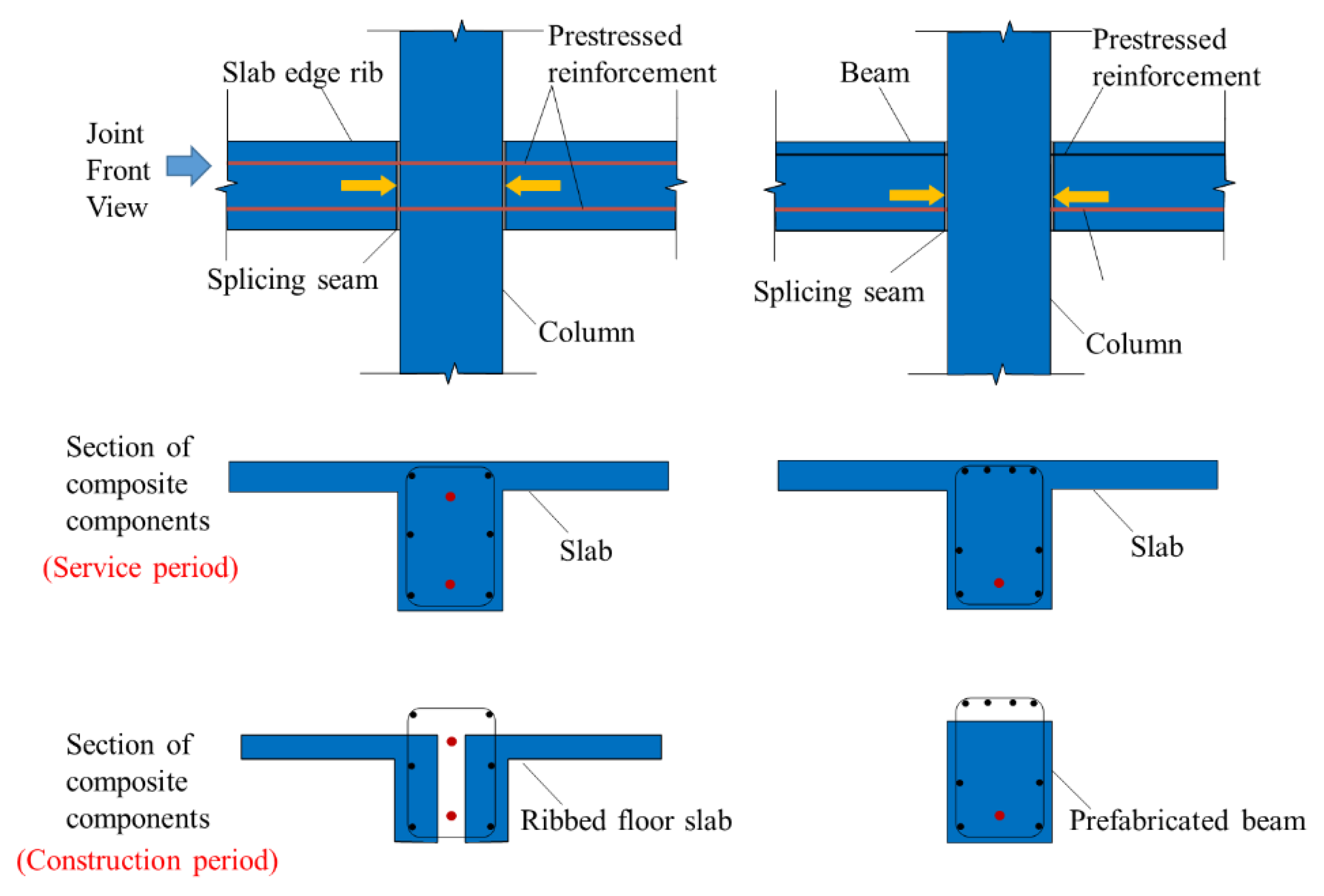
Figure 2.
Schematic diagram of joint deformation.
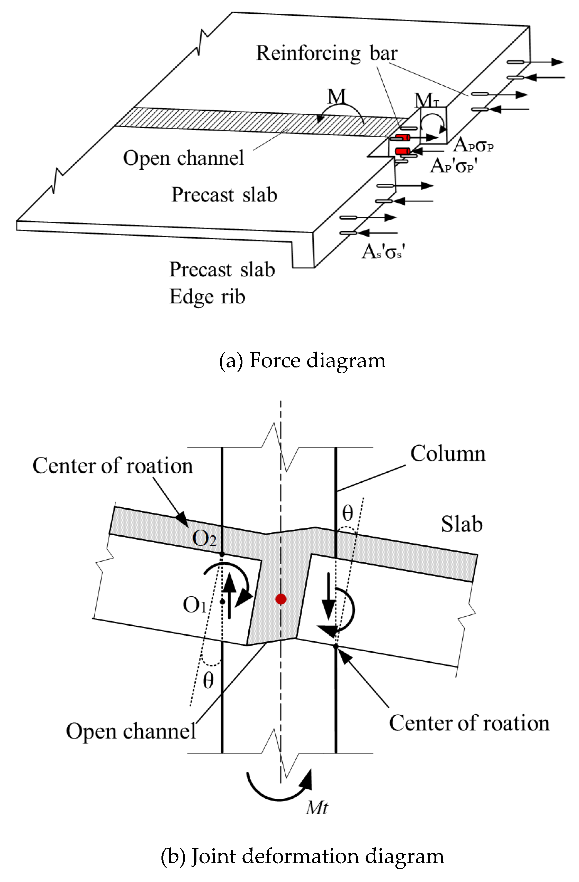
Figure 3.
Configuration and dimensions of specimens.
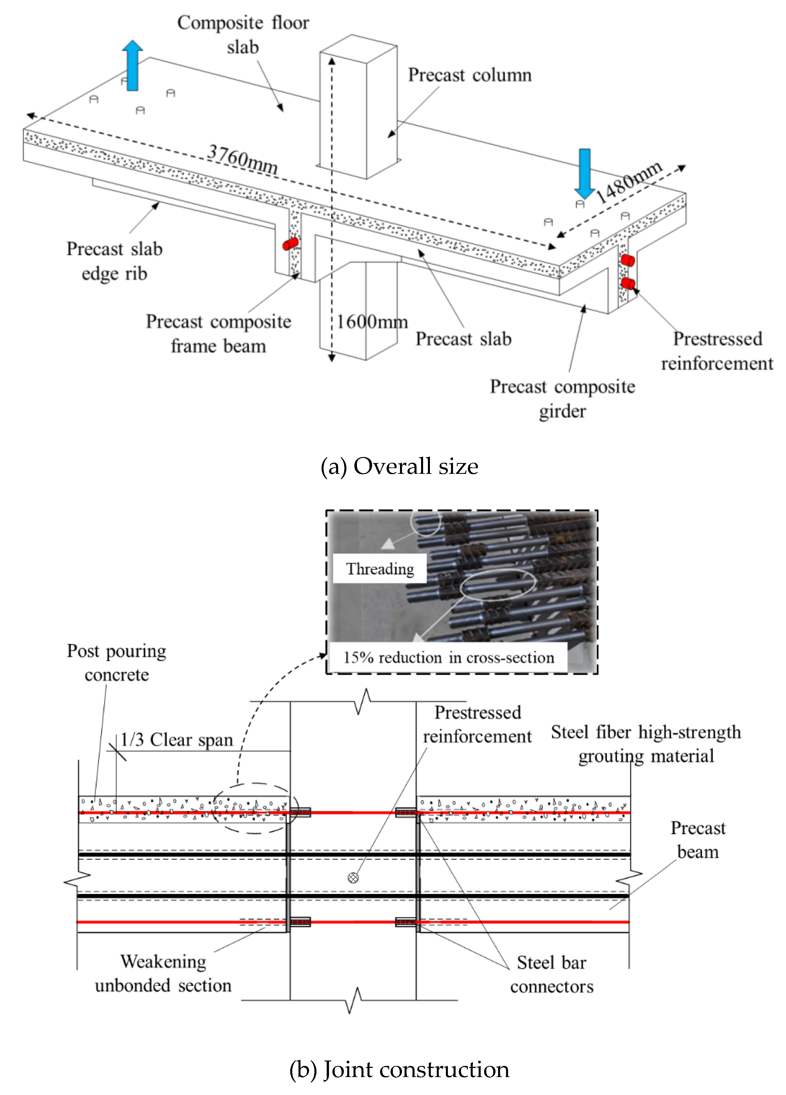
Figure 4.
Reinforcement details of specimens.
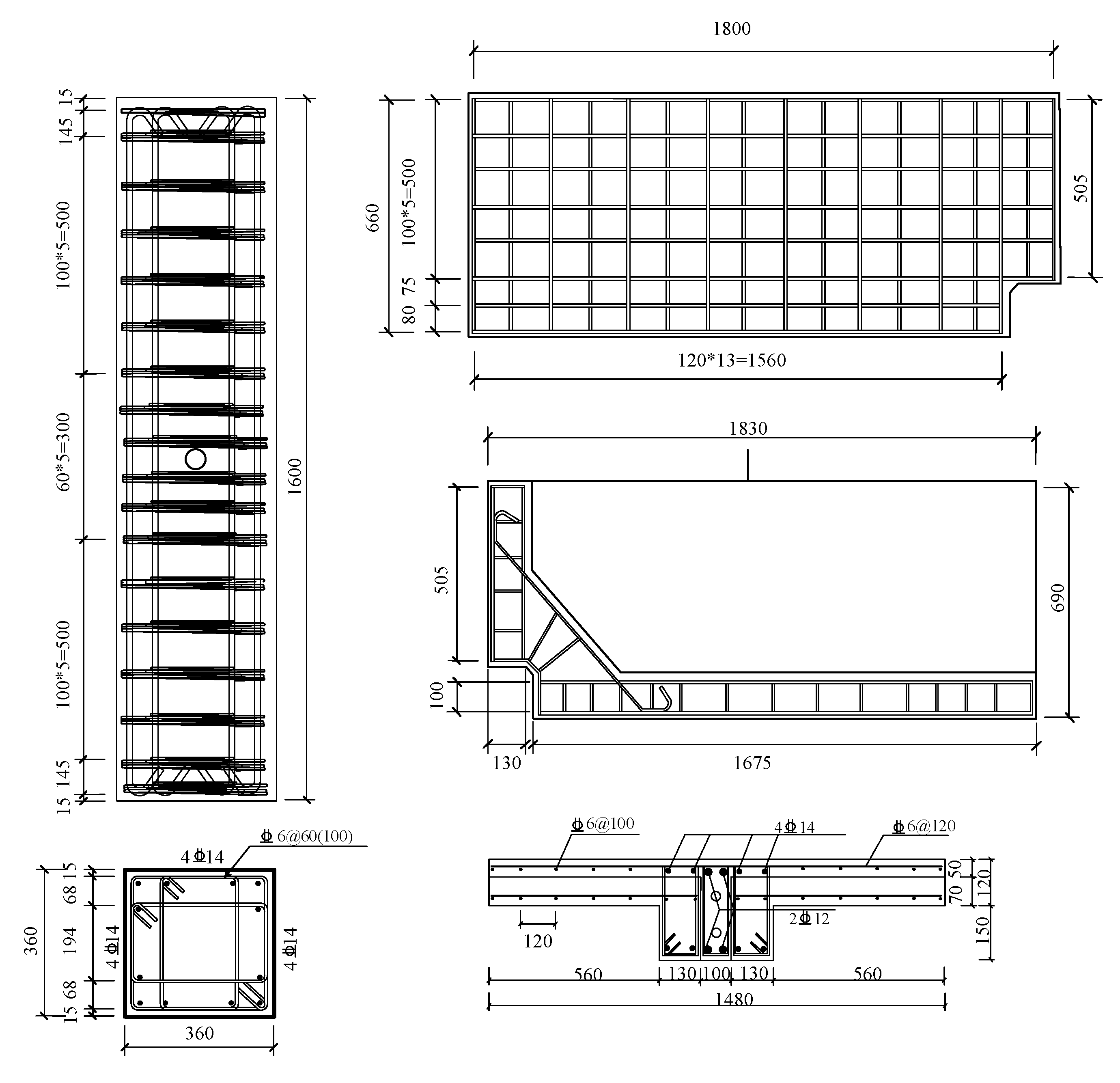
Figure 5.
Test setup.
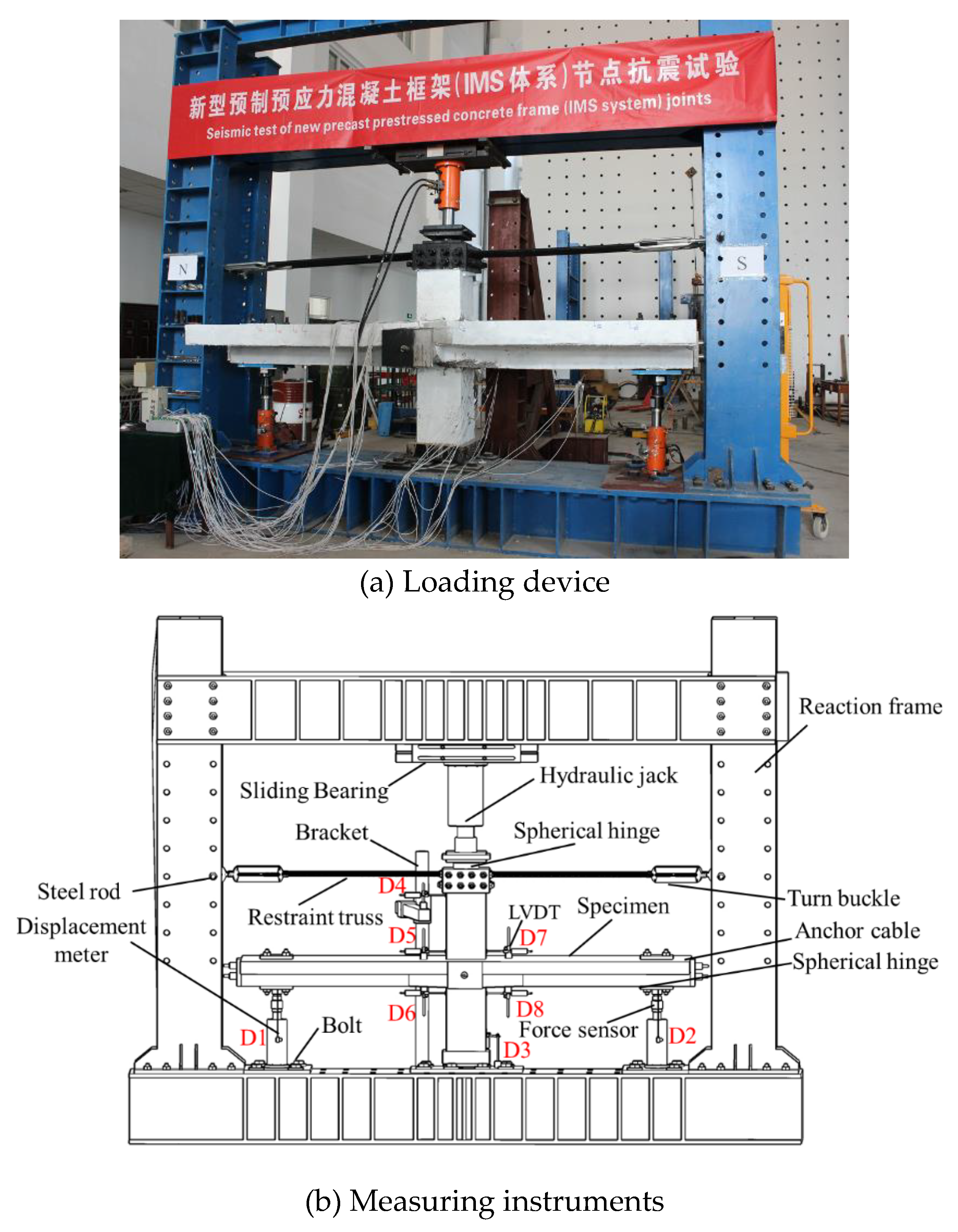
Figure 6.
Test loading process.
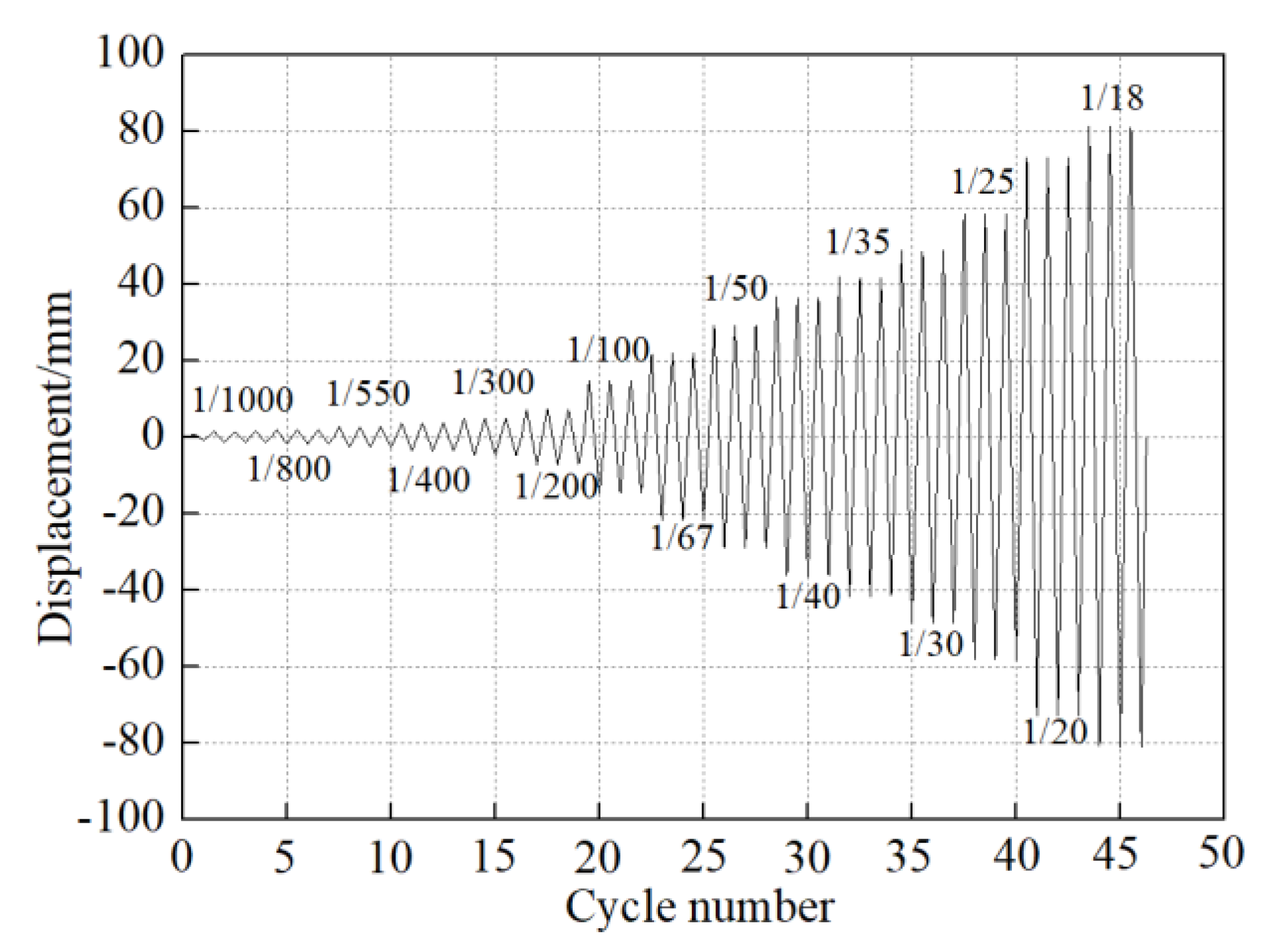
Figure 7.
Test phenomena during loading.
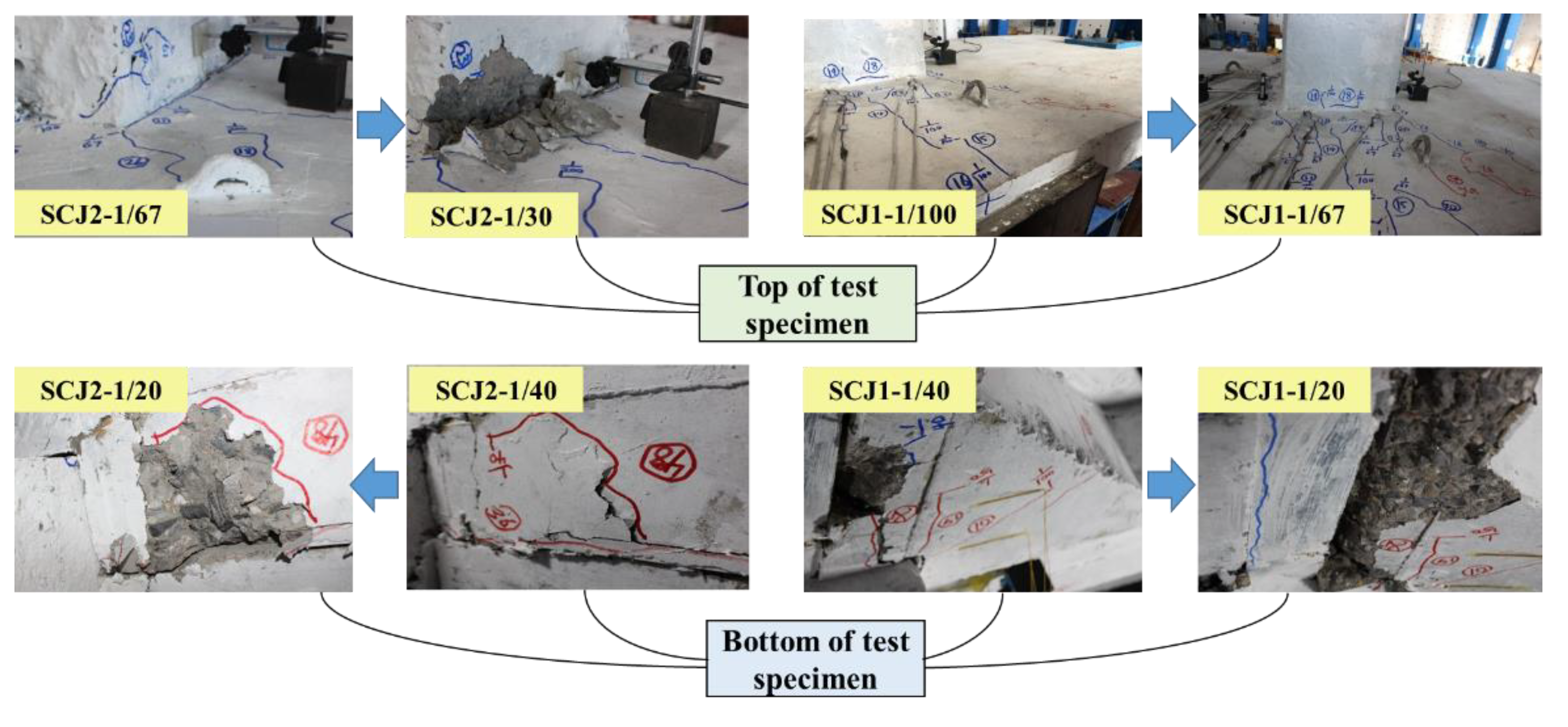
Figure 8.
Load-displacement curve.
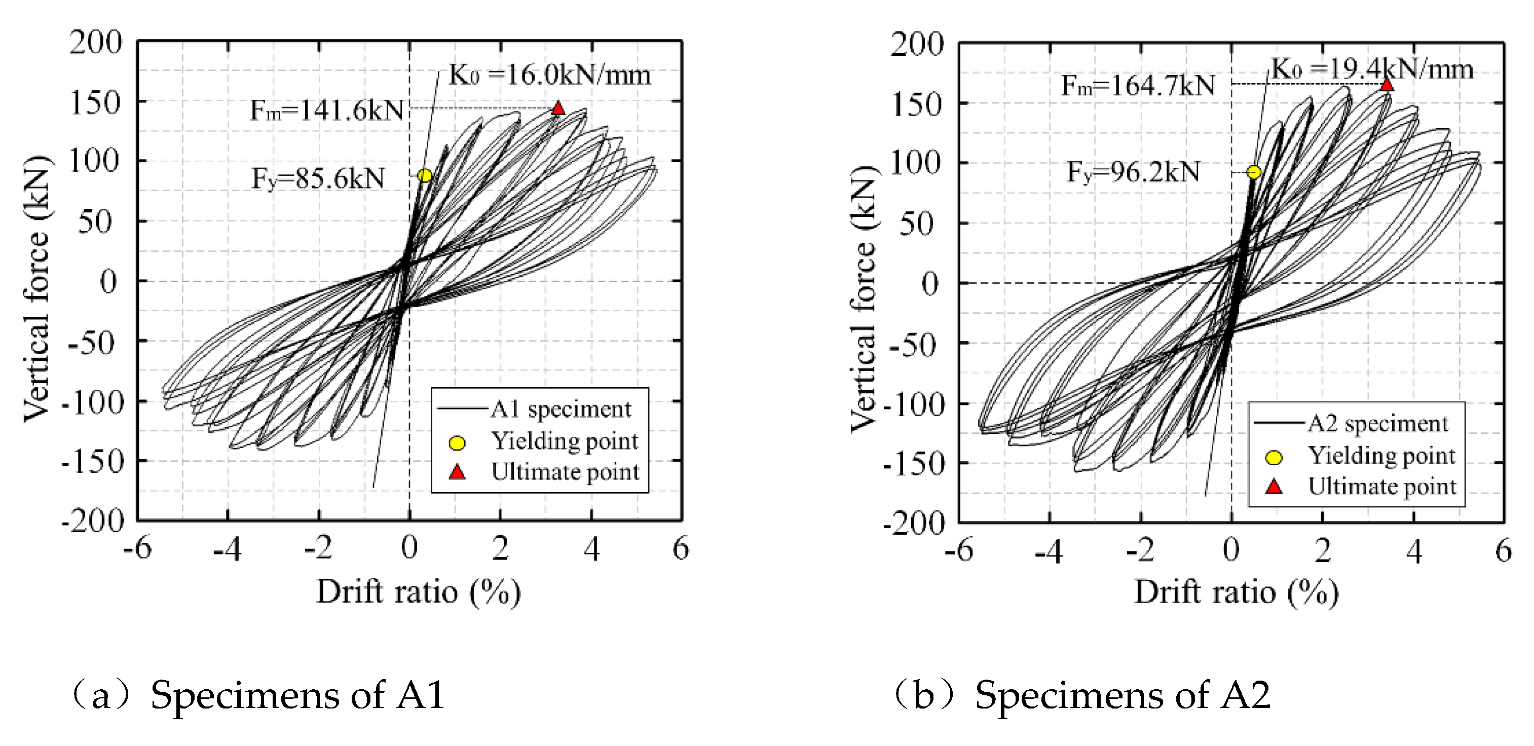
Figure 9.
Skeleton curves.
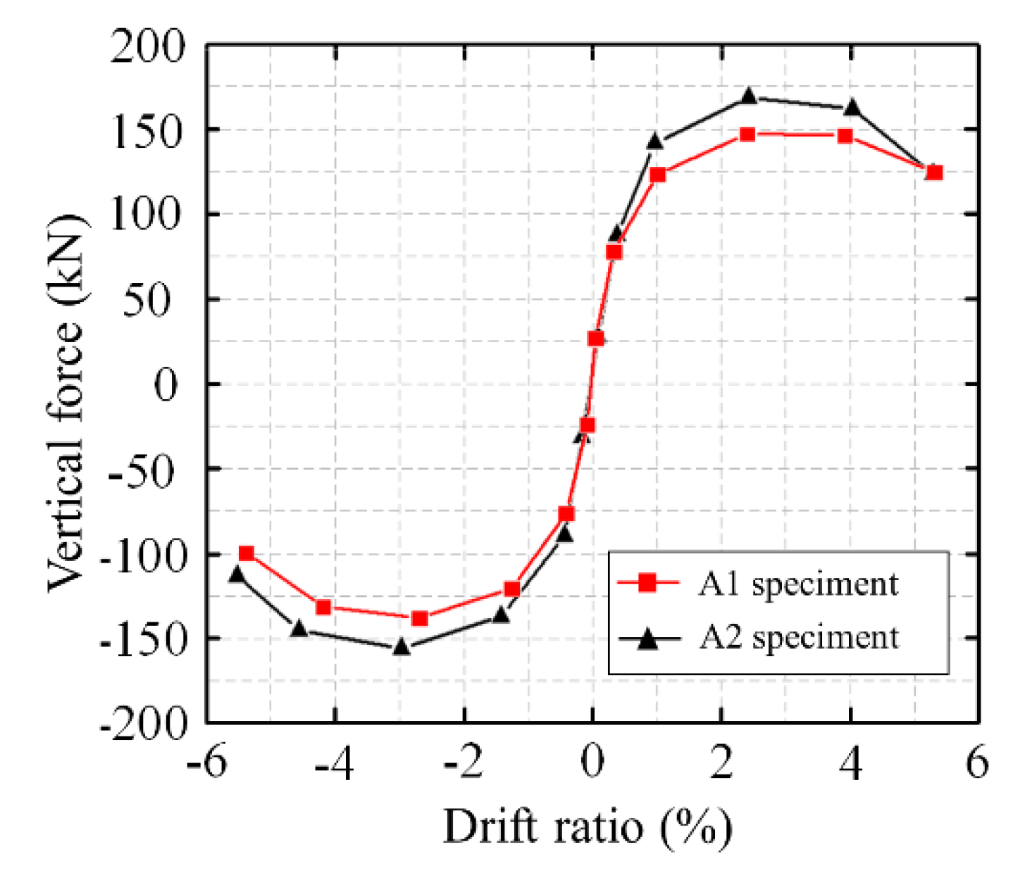
Figure 10.
Cumulative energy dissipation curves.
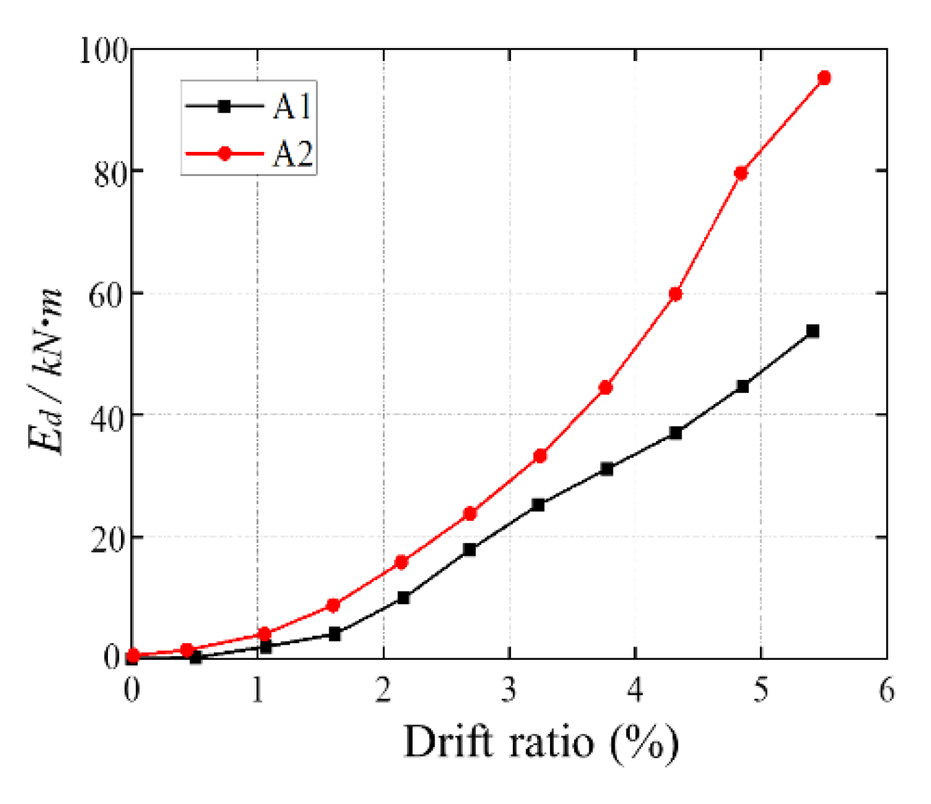
Figure 11.
Finite element model of middle joint specimen.
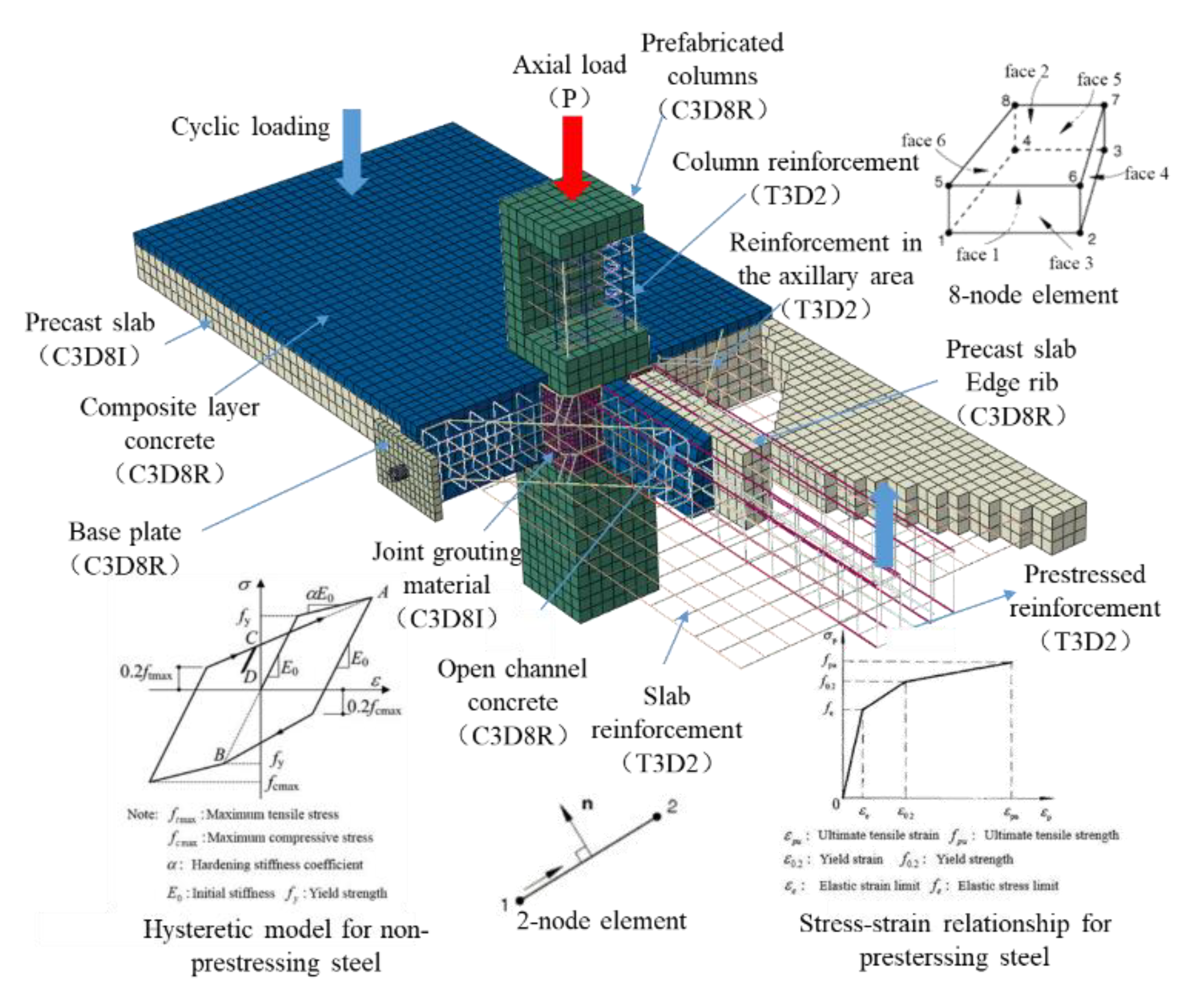
Figure 12.
Simulation and test hysteretic curves.
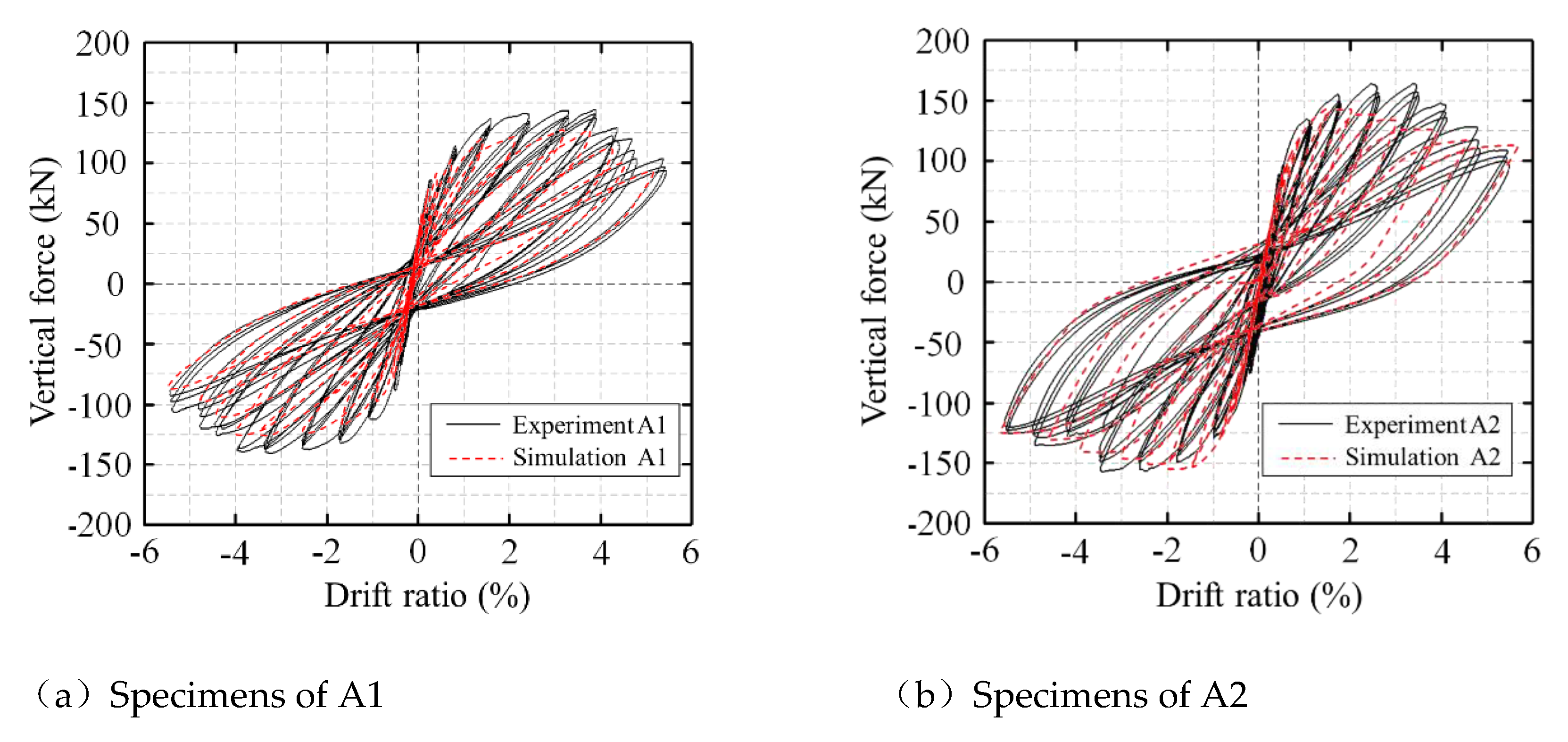
Figure 13.
Stress nephogram of A1 reinforcement and concrete.
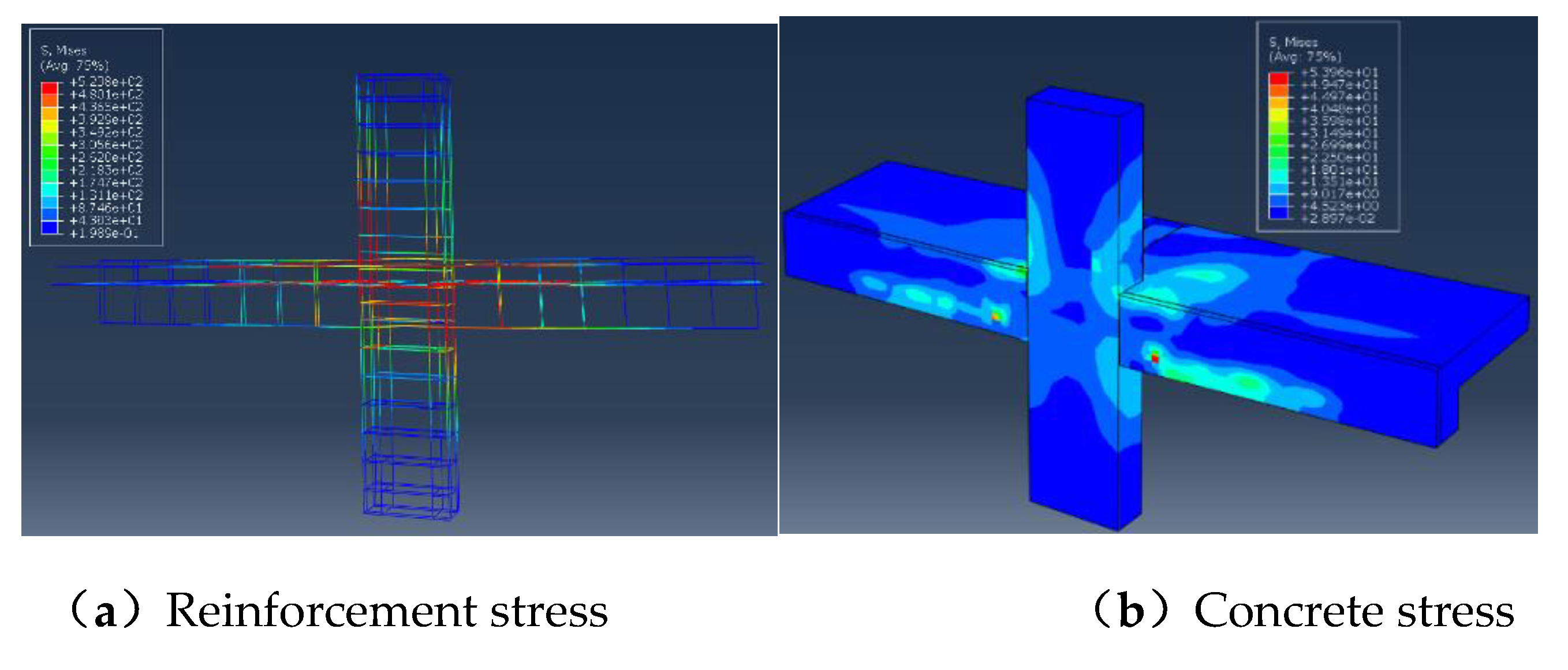
Figure 14.
Influence of overlay settings on joint deformation.
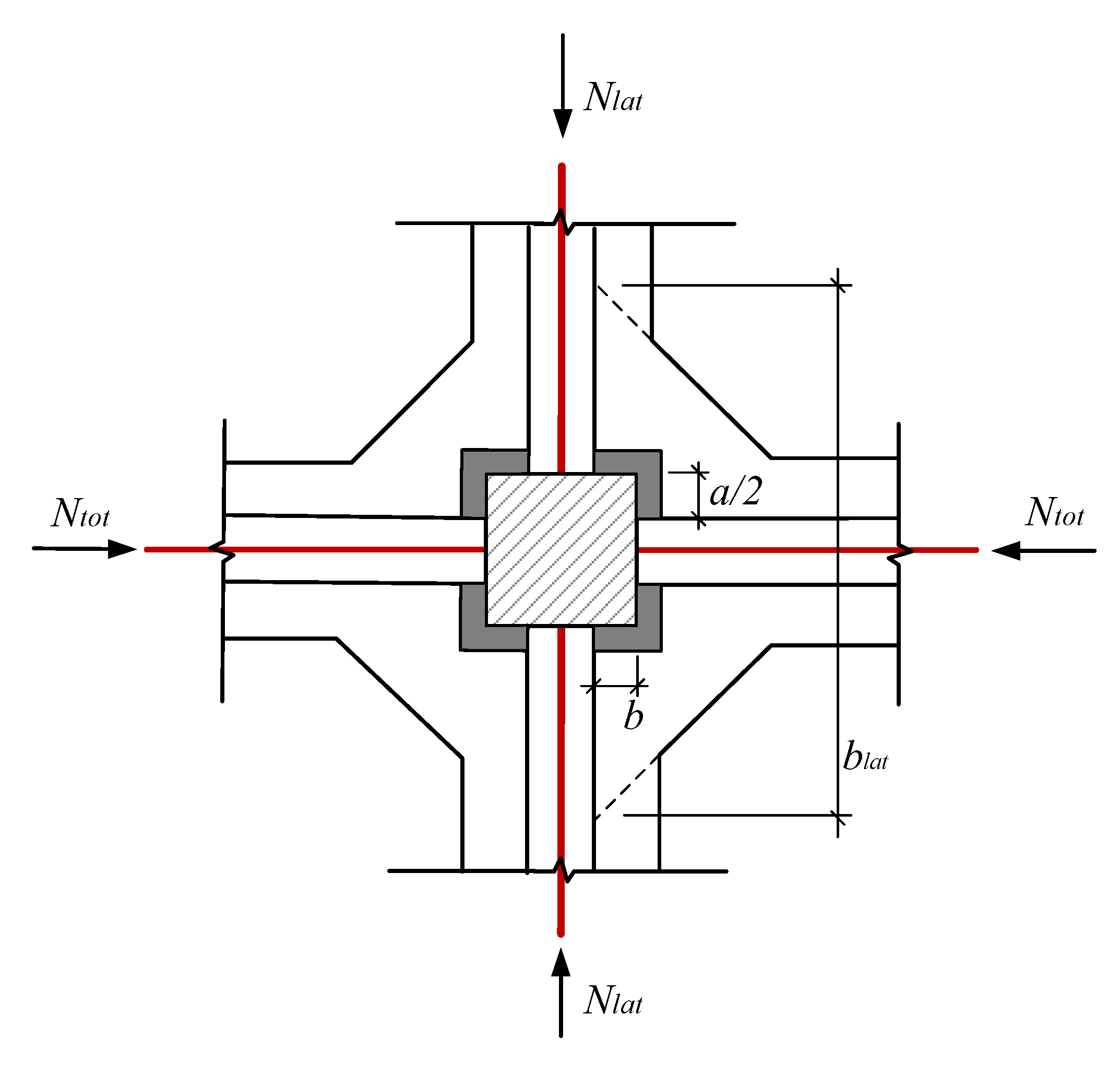
Figure 15.
The skeleton curves of A1 under different friction coefficients.
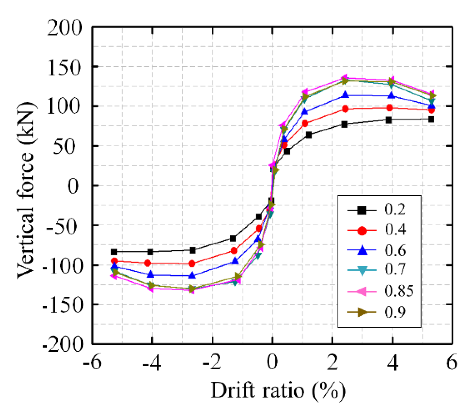
Figure 16.
The skeleton curves of A1 under different laminated layer.
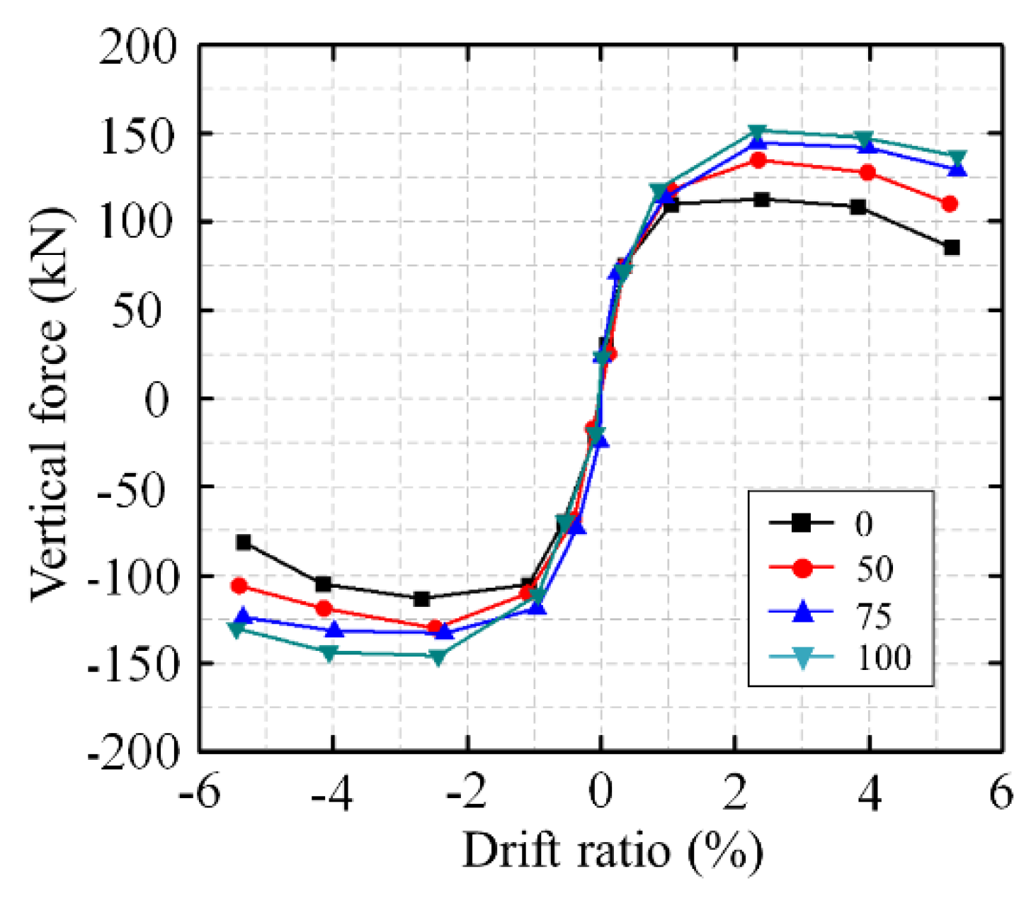

Table 1.
Mechanical properties of steel.
| Steel type | Diameter (mm) | Strength/ Mpa | Elastic modulus/(Mpa) | Elongation Agt/% |
|
| Yielding | Ultimate | ||||
| Reinforced bar | 16 | 482 | 657 | 2.17e5 | 20.1 |
| 12 | 441 | 603 | 2.05e5 | 22.6 | |
| 8 | 428 | 584 | 2.11e5 | 23.7 | |
| 6 | 406 | 552 | 2.05e5 | 24.3 | |
| Strands | 1×7Φs15.2 | 1786 | 1928 | 1.98e5 | 6.5 |
Note: the mechanical property data is the average of the test results of 3 specimens[14].
Table 2.
Test mix proportion parameters and results.
| Water cement ratio | Volume content/% | Compressive strength/MPa | Flexural strength/MPa | Fluidity /mm |
|||||
| 1d | 3d | 28d | 1d | 3d | 28d | Initial value | 30min | ||
| 0.145 | 1.5 | 65.0 | 72.7 | 80.5 | 8.4 | 11.8 | 10.9 | 305 | 285 |
Disclaimer/Publisher’s Note: The statements, opinions and data contained in all publications are solely those of the individual author(s) and contributor(s) and not of MDPI and/or the editor(s). MDPI and/or the editor(s) disclaim responsibility for any injury to people or property resulting from any ideas, methods, instructions or products referred to in the content. |
© 2024 by the authors. Licensee MDPI, Basel, Switzerland. This article is an open access article distributed under the terms and conditions of the Creative Commons Attribution (CC BY) license (http://creativecommons.org/licenses/by/4.0/).
Copyright: This open access article is published under a Creative Commons CC BY 4.0 license, which permit the free download, distribution, and reuse, provided that the author and preprint are cited in any reuse.


