Submitted:
22 April 2024
Posted:
23 April 2024
You are already at the latest version
Abstract
This study presents an effective control algorithm to improve the robustness of fast steering mirror (FSM)-based laser beam steering systems against dynamic disturbances such as repetitive disturbances resulting from operating conditions. A stable control system must be able to maintain the required high-precision control even when dynamic disturbances affect the FSM system. In this study, an improved control method is proposed using an internal model principle (IMP)-based nonlinear controller with a disturbance observer (DOB) for the FSM system. This IMP-based controller with DOB can attenuate the residual control error signal under dynamic disturbance conditions.
Keywords:
laser beam steering
; fast steering mirror
; adaptive feedforward control
; tip-tilt control system
; internal model principle
; disturbance observer
1. Introduction
Fast steering mirror (FSM)-based laser beam steering (LBS) systems are used in various optical tracking control systems, such as long-range laser communication, line-of-sight (LOS) stabilization, and adaptive optics [1,2,3,4]. In addition, these systems are increasingly mounted on moving platforms, such as spacecraft, satellites, airplanes, ships, and vehicles [5,6,7,8]. However, the LBS control system must be maintained the aiming point in the target plane while minimizing factors that cause jitter in the presence of disturbances. In applications, jitter usually is caused by vibration of the optical bench through which the laser beam travels [9].
The goal of designing a high-precision tip-tilt controller for FSM systems is ensuring that the voice coil actuator (VCA) or piezoelectric (PZT) actuator maintains an extremely small rotational position in the presence of dynamic disturbances to fulfill the required operational conditions. Therefore, FSM systems should be designed with a tip-tilt controller to realize highly precise control with fast response and good disturbance-rejection performance [10]. Gu G Y et al. suggested that the effects of vibration on PZT actuators should be eliminated [11]. Secondly, to eliminate the main resonant modes of FSM systems, Ling et al. and Wadikhaye S P et al. developed the notch filter as an effective method [12,13]. Clayton G M et al. and Wang G et al. developed a feedforward controller [14,15]. Schitter G et al. and Gul G Y et al. developed the input-shaping controller and integral resonant controller, respectively [16,17].
In general, several methods can be adopted to improve the dynamic disturbance-rejection performance of the high-precision control system. Particularly, to cancel out the periodic disturbances resulting from the operational condition of the target platform, repetitive controllers and adaptive feedforward cancellation (AFC) schemes have been applied [18]. Repetitive control technologies are the most widely used, either as internal or external model-based controllers [19] Discrete-time repetitive controllers based on the internal model principle (IMP) have been synthesized and analyzed [20]. The most common approach is based on the IMP, which states that a model of the disturbance generation system must be included in the feedback system to realize disturbance cancellation. However, owing to the hardware limitations of the servo loop in our FSM control system, classical AFC schemes cannot be used to precisely control the rotational position.
Adding a disturbance observer (DOB) to the base feedback controller greatly generally enhances disturbance attenuation. The DOB structure is suitable for real-time implementation owing to its simplicity. DOB implementation typically imposes a very light computational burden, and it is inexpensive because additional sensors are not required. Recently, several studies have developed robust FSM control systems by using DOB-based controllers to improve tip-tilt control performance.
In this study, we propose a more reliable tip-tilt control algorithm by using an IMP-based controller with DOB for the FSM system to reduce the control error signal (CES) in the presence of dynamic disturbances. In experiments involving an analysis of periodic disturbances under operating conditions, we report the use of IMP-based control with a DOB to attenuate disturbances of a few frequencies. The remainder of this the paper is organized as follows: Section 2 introduces the basic FSM control system. In Section 3, a IMP-based controller with a DOB is described, and its performance is analyzed. Section 4 describes the experiments conducted to verify the proposed method. Finally, our concluding remarks are presented in Section 5.
2. FSM Control System
2.1. Dynamic Characteristics of Piezoelectric (PZT) Actuator
The conventional approach to designing a high-precision FSM control system for tip-tilt control involves the use of a piezoelectric (PZT) actuator. The frequency response function (FRF) of the actuating plant is usually obtained using the sine-sweep method. The real plant consists of a PZT actuator, DC-DC-converter-type amplifier, and sensor amplifier. The dynamic specifications of the real plant indicate that the resonance frequency is 450.2 Hz. Additionally, the DC sensitivity, gain of the voltage amplifier, and gain of the sensor amplifier are 168.3 µrad/V, 10 V/V, and 0.0059 V/ µrad, respectively. Therefore, the real plant can be modeled as a fifth-order transfer function, as follows:
The FRF of the real actuator and its modeling plant are illustrated in Figure 1. In addition, the dynamic characteristics of the real plant are summarized in Table 1.
Moreover, the open-loop transfer function of a nominal plant is expressed as follows:
where ζ and ωn are the damping ratio and resonance frequency of the actuator, respectively. KFSM denotes the DC gain of the nominal plant (i.e., FSM actuation system), which is composed of the DC gain of the PZT actuator and the gains of the position sensor and PZT actuator driver.
The real plant and digital signal processor (DSP) platform used to evaluate the control performance of the FSM control system are depicted in Figure 2. A Scalexio AutoBox (dSPACE) is used to control the FSM control system. In addition, an S-340 piezo tip-tilt platform and an amplifier module (PI Ceramic GmbH) are used in the tip-tilt actuating platform.
2.1. Tip-Tilt Controller of FSM Control System
Proportional-integral (PI) controllers are widely used in real control systems as the tip-tilt controllers of FSM control systems. Moreover, tip-tilt controllers are designed to achieve the designed gain margin, phase margin, crossover frequency, and loop gain. Although it is feasible to obtain a wide crossover frequency, the crossover frequency is limited by the sampling frequency of the DSP, feedback sensor signal, and other components. The open-loop transfer function of the PI controller designed for the FSM control system in this study is depicted in Figure 3, and its crossover frequency, gain margin, phase margin, and loop gain are 91.1 Hz, 11.8 dB, 68.7 °, and >30 dB, respectively. Moreover, the disturbance-rejection performance of the designed PI controller for the FSM control system is illustrated in Figure 4.
3. Disturbance-Rejection Control Algorithm for FSM System
3.1. IMP-Based Controller
To enhance tip-tilt control performance under dynamic disturbance conditions, the control algorithm in the linear feedback loop with IMP-based controller can be proposed for the FSM control system. Because it is possible to implant a disturbance model internally that is identical to a periodic disturbance, in a feedback controller with IMP, the disturbance can be cancelled out faster and more accurately than in an unmodified tip-tilt controller, as illustrated in Figure 5. In addition, the proposed IMP-based controller modifies the AFC algorithm more easily considering the frequencies of various disturbances. However, when the rotational position exceeds the predefined threshold in the presence of nonperiodic disturbances such as external shock, the feedback loop through the IMP-based controller is opened, as depicted in Figure 5, because the control performance of the system for nonperiodic disturbances may degrade. Therefore, IMP-based controllers are typically used in control systems as nonlinear controllers.
The transfer function for implementation in the feedback loop using the IMP-based controller is denoted CIMP. The sampling time, periodic frequency, adaptive gain, and control gains of the IMP controller are denoted Ts, ω, g, and ϕ, respectively. The transfer functions for continuous time and discrete time are denoted by CIMP(s) and CIMP(z), respectively, and expressed as follows:
For cancellation of periodic disturbances, the control input has the following form in discrete time:
The parameter update laws are as follows:
where parameter e(k) is the control error, and g is the adaption gain of the IMP controller. Because g is obtained experimentally, if it is large, the transient response is amplified. Nonetheless, the control performance of the system can be extremely unstable in other frequency regions because the sensitivity transfer function of the control system in those regions may attenuate in accordance with the Bode integral theorem. Therefore, the fundamental design of the IMP-based controller is such that the linear feedback system eliminates the disturbances whose frequencies correspond to those at which the control gain of the IMP is infinite. In addition, the IMP control gain ϕ at ω (periodic frequency) is calculated as follows:
where P(s) is the designed FSM control system, and Co(s) is the PI controller.
As illustrated in Figure 6, according to the results of the experiment conducted to analyze uncompensated CES, periodic disturbances of several frequencies in the CES are generated primarily by the operating conditions. In particular, in the analyzed residual CES, periodic disturbance characteristics are generated during tip-tilt control owing to vibration of the platform cooling fan. The power spectrum of the uncompensated CES shows that the disturbance occurs at integer multiples of the fundamental rotating frequency of the cooling fan. In addition, two specific peaks are formed at 65 and 71 Hz, and they are not harmonic frequency components of the fundamental rotating frequency of the cooling fan. These disturbance frequencies may be attributed to mechanical resonances of the platform. The first harmonic frequency component (i.e., 60 Hz) was originally used for PI control of the FSM system. Therefore, to eliminate periodic disturbances such as the harmonic component resulting from rotation conditions of the cooling fan and mechanical resonance frequencies of the platform, the FSM control system is designed using an IMP-based controller, as illustrated in Figure 7 and Figure 8. The control input is calculated using the control law expressed in Eq. (5). The phase angles of the closed-loop transfer function at ω1 = 60 Hz, ω2 = 65 Hz, and ω3 = 71 Hz are estimated as ϕ1 = 80°, ϕ2= 78°, and ϕ3= 77°, respectively. This phase information is used in the adaptation law, which is expressed in Eqs. (6) and (7). As depicted in Figure 7 and Figure 8, the adaptive gain of g in case of the IMP-based controller is set to a suitable value. Consequently, the control performance of the IMP-based controller is over 20 dB greater than that of the PI controller for a few frequency components.
According to the experimental results of the PI controller for FSM control with and without the IMP-based AFC, the target rotational position was maintained successfully at 500 μrad. Figure 12 shows that the power spectrum of the residual CES for the PI controller without the IMP-based controller was 7.97 μrad. When we used the IMP-based controller at 60, 65, and 71 Hz in the FSM control system, the RMS values of the CES were 7.43, 7.17, and 6.05 μrad, respectively, as illustrated in Figures 12(a)–(c). Additionally, we applied the IMP-based controller to multiple frequency components. When the IMP-based controller was used at 60 and 65 Hz in the FSM control system, the RMS value of the CES was 6.00 μrad. Furthermore, when the IMP-based controller was used at 60 and 71 Hz in the FSM control system, the RMS of the CES was 5.41 μrad, as illustrated in Figure 9(d) and (e). These results indicated that the IMP-based controller was efficient at suppressing periodic disturbances in the FSM system.
3.2. IMP-Based Controller with DOB
The design of the IMP-based controller with DOB, which aims to compensate for the presence of disturbances, is simple to implement because the IMP-based controller with DOB can be fabricated by attaching the DOB and IMP to the original FSM control system. Theoretically, the IMP-based controller with DOB can be designed as an extended structure in the feedback control loop.
In general, the DOB is composed of an inverse nominal plant and a low-pass Q filter. In this study, we used a binomial Q filter as the DOB. Figure 10 presents a schematic diagram of the FSM control system with the DOB. The open-loop transfer function of a continuous system is expressed as follows:
where t is a time constant, and ami represents the binomial coefficients calculated as (m! / m − i)! i!), where m and n are the orders of the denominator and numerator, respectively (m ≥ n). Generally, the stability of a control system is in a trade-off relationship with the bandwidth of the Q filter. Therefore, the bandwidth of the Q filter must be selected experimentally to maximize the stability of the control system. In this study, the binomial Q20 and Q30 filters were used as the DOB-based controller of the FSM system, as illustrated in Figure 11. This is because the stability of the control system can be estimated from the residual CES, which is the experimental result. When the Q20 and Q30 filters were used, the FSM control system was able to suppress disturbances effectively. Moreover, the FSM control system was able to suppress disturbances effectively in low-frequency regions with bandwidths of 15 and 30 Hz.
The loop gain of the control system should be high in the frequency domain of dynamic disturbances. Therefore, the loop gain of the FSM control system using the IMP-based controller with DOB was set to be higher than the loop gain of the IMP-only-based controller. Moreover, the control loop gain was improved by increasing the bandwidth of the Q filter. As the control performance, the open-loop transfer functions of the overall FSM control system using the IMP-based controller with DOB are illustrated in Figure 12, Figure 13, Figure 14 and Figure 15. The open-loop transfer function of the FSM control system using the IMP with the DOB is expressed as follows:
4. Experimental Results of DOB-Based FSM Control System
In this study, we compared two main cases. First, in the IMP-based controller, the Q20 filter was used as the DOB. Second, in the IMP-based controller, the Q30 filter was used as the DOB. Moreover, the bandwidths of each of the binomial Q20 and Q30 filters were set to 15 Hz and 30 Hz. The target rotational position was successfully maintained at 500 μrad. As illustrated in Figure 15, the power spectrum of the residual CES of the IMP-based PI controller was 7.97 μrad. In the first case, when we used the IMP-based controller with the DOB (Q20 filter 15 Hz) at 60, 65, and 71 Hz in the FSM control system, the CES values were 6.96, 6.75, and 5.73 μrad, respectively, as illustrated in Figure 16(a). When we used the IMP-based controller with the DOB (Q20 filter 30 Hz) at 60, 65, and 71 Hz in the FSM control system, the CES values were 6.76, 6.57, and 5.51 μrad, respectively, as illustrated in Figure 16(b). In the second case, when we used the IMP-based controller with the DOB (Q30 filter 15 Hz) at 60 Hz, 65 Hz, and 71 Hz in the FSM control system, the CES values were 6.49, 6.28, and 5.36 μrad, respectively, as depicted in Figure 16(c). When we used the IMP-based controller with the DOB (Q30 filter 30 Hz) at 60, 65, and 71 Hz in the FSM control system, the CES values were 6.18, 6.05, and 5.24 μrad, respectively, as depicted in Figure 16(d).
To enhance the control rejection performance of the FSM system, we applied the IMP-based controller with multiple frequency components. For the IMP-based controller with a Q20 filter having bandwidths of 15 and 30 Hz as the DOB, respectively, the CES values were 5.51 and 5.57 μrad, respectively. For the IMP-based controller with a Q30 filter having bandwidths of 15 and 30 Hz as the DOB, the CES values were 5.36 and 5.24 μrad, respectively, as depicted in Figures 16(a)–(d). These results indicated that the performance of the IMP-based controller with the DOB was efficient in terms of suppressing periodic disturbances in the FSM system.
4. Conclusions
In this study, we improved the disturbance-rejection performance of an FSM control system by using an IMP-based controller with DOB to improve the control performance.
When the IMP-based controller with DOB (Q20 filter 15 Hz) was used at 60, 65, and 71 Hz, the CES values decreased by approximately 12.67, 15.3, and 28.1%, respectively, compared to those when using the IMP-based controller alone. When the IMP-based controller with DOB (Q20 filter 30 Hz) was used at 60, 65, and 71 Hz, the CES values decreased by approximately 15.1, 17.5, and 30.9%, respectively, compared to those when using the IMP-based controller alone. When the IMP-based controller with DOB (Q30 filter 15 Hz) was used at 60, 65, and 71 Hz, the CES values decreased by approximately 18.5, 21.1, and 32.8%, respectively, compared to those when using the IMP-based controller alone. When the IMP-based controller with DOB (Q30 filter 30 Hz) was used at 60, 65, and 71 Hz, the CES values decreased by approximately 22.4, 24.1, and 34.2%, respectively, compared to those when using the IMP-based controller alone.
Furthermore, to improve the disturbance-rejection performance of FSM control system by using IMP-based controller with DOB, the IMP-based controller was set to have multiple frequency components. As summarized in Table 3, when we used the IMP-based controller with DOB, the CES values were lower than those obtained when using the IMP-based controller alone. These results indicated that the performance of the proposed controller was superior to that observed in a previous study of FSM control systems.
Acknowledgments:
This work was supported by an Agency for Defense Development (ADD) grant funded by the Government of the Republic of Korea in 2024.
Conflicts of Interest
The authors declare no conflicts of interest.
References
- Sun, C.; Ding, Y.; Wang, D.; Tian, D. Backscanning step and stare imaging system with high frame rate and wide coverage. Appl. Opt. 2015, 54, 4960–4965. [Google Scholar] [CrossRef] [PubMed]
- Chen, N.; Potsaid, B.; Wen, J.T.; Barry, S.; Cable, A. Modeling and control of a fast steering mirror in imaging applications. In Proceedings of the IEEE International Conference on Automation Science and Engineering (CASE 2010); 2010; pp. 27–32. [Google Scholar]
- Park J H, Lee H S, Lee J H, et al. “Design of a piezoelectric-driven tilt mirror for a fast laser scanner,” JAP. 2012, 51(9S2): 09MD14.
- Liu, W.; Yao, K.; Huang, D.; Lin, X.; Wang, L.; Lv, Y. Performance evaluation of coherent free space optical communications with a double-stage fast-steering-mirror adaptive optics system depending on the Greenwood frequency. Opt. Express 2016, 24, 13288–302. [Google Scholar] [CrossRef] [PubMed]
- Wang C, Hu L, Xu H, et al. “Wavefront detection method of a single-sensor based adaptive optics system,” Opt. Exp. 2015, 23, 21403–21414.
- Pan J W, Chu J, Zhuang S, et al. “A new method for incoherent combining of far-field laser beams based on multiple faculae recognition,” In: Proc. SPIE 10710, Young Scientists Forum. 2017, 1071034.
- Loney G L, “Design of a small-aperture steering mirror for high-bandwidth acquisition and tracking,” Opt. Eng. 1990, 29, 1360–1365.
- Merritt, P.H.; Albertine, J.R. Beam control for high-energy laser devices. Opt. Eng. 2013, 52, 021005–1. [Google Scholar] [CrossRef]
- Perram, G.P.; Marciniak, M.A.; Goda, M. High-energy laser weapons: technology overview. In Defense and Security. In Proceedings of the SPIE 5414, Laser Technologies for Defense and Security; 2004; pp. 1–25. [Google Scholar]
- Ghai D P, Venkatesh A, Swami H R, Kumar A, “Large aperture, tip tilt mirror for beam jitter correction in high power lasers”. Defense Sci. J. 2013, 63, 606–610. [CrossRef]
- Kluk, D.J.; Boulet, M.T.; Trumper, D.L. A high-bandwidth, high-precision, two-axis steering mirror with moving iron actuator. Mechatronics 2012, 22, 257–270. [Google Scholar] [CrossRef]
- Nam B U, Gimm H I, Kang D W, et al. “Design and analysis of a tip-tilt guide mechanism for the fast steering of a large-scale mirror,” Opt. Eng. 2016, 55, 106120.
- Nam B U, Gimm H I, Kim J G, et al. “Development of a fast steering mirror of large diameter,” In: Proc. SPIE. 2017, 10249, 102490R.
- Gu G Y, Zhu L M, Su CY, et al. , “Modeling and control of piezo-actuated nanopositioning stages: A survey,” IEEE Trans. Auomation Sci. Eng. 2016, 13, 313–332.
- Ling, J.; Feng, Z.; Ming, M.; Xiao, X. Damping controller design for nanopositioners: A hybrid reference model matching and virtual reference feedback tuning approach. Int. J. Precis. Eng. Manuf. 2018, 19, 13–22. [Google Scholar] [CrossRef]
- Wadikhaye, S.P.; Yong, Y.K.; Bhikkaji, B.; Moheimani, S.O.R. Control of a piezoelectrically actuated high-speed serial-kinematic AFM nanopositioner. Smart Mater. Struct. 2014, 23, 025030. [Google Scholar] [CrossRef]
- Clayton, G.M.; Tien, S.; Leang, K.K.; Zou, Q.; Devasia, S. A Review of Feedforward Control Approaches in Nanopositioning for High-Speed SPM. J. Dyn. Syst. Meas. Control. 2009, 131, 061101. [Google Scholar] [CrossRef]
- McEver, M.A.; Cole, D.G.; Clark, R.L. Adaptive feedback control of optical jitter using Q-parameterization. Opt. Eng. 2004, 43, 904–910. [Google Scholar] [CrossRef]
- Wang G, Chen G, Bai F, “High-speed and precision control of a piezoelectric positioner with hysteresis, resonance and disturbance compensation,” Microsyst. Technol. 2016, 22, 2499–2509.
- Schitter, G.; Thurner, P.J.; Hansma, P.K. Design and input-shaping control of a novel scanner for high-speed atomic force microscopy. Mechatronics 2008, 18, 282–288. [Google Scholar] [CrossRef]
Figure 1.
Frequency response and linear transfer function of real plant.
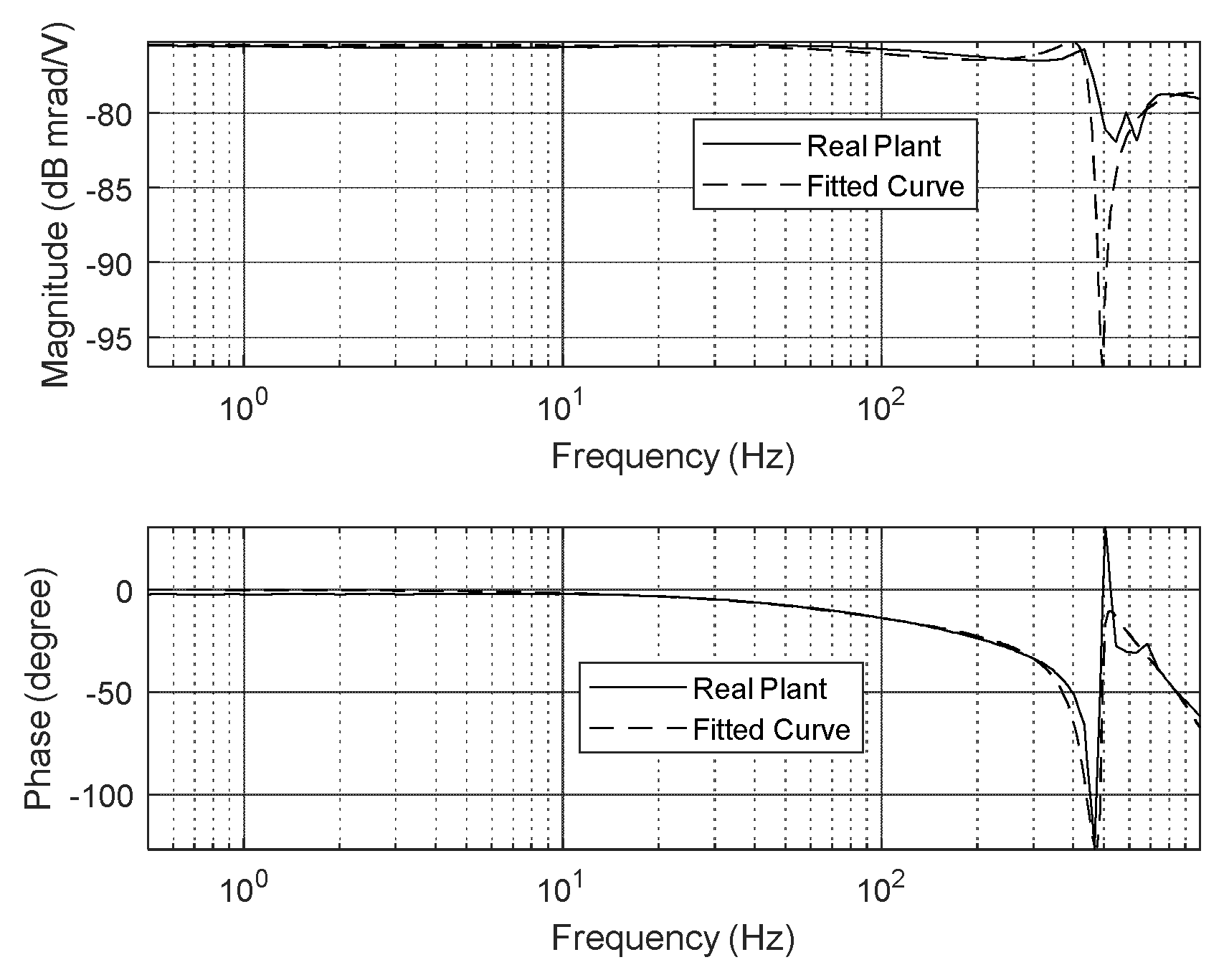
Figure 2.
Experimental setup for fast steering mirror (FSM) control system: (a) Scalexio AutoBox (dSPACE), and (b) tip-tilt actuating platform (PI Ceramic GmbH).
Figure 2.
Experimental setup for fast steering mirror (FSM) control system: (a) Scalexio AutoBox (dSPACE), and (b) tip-tilt actuating platform (PI Ceramic GmbH).
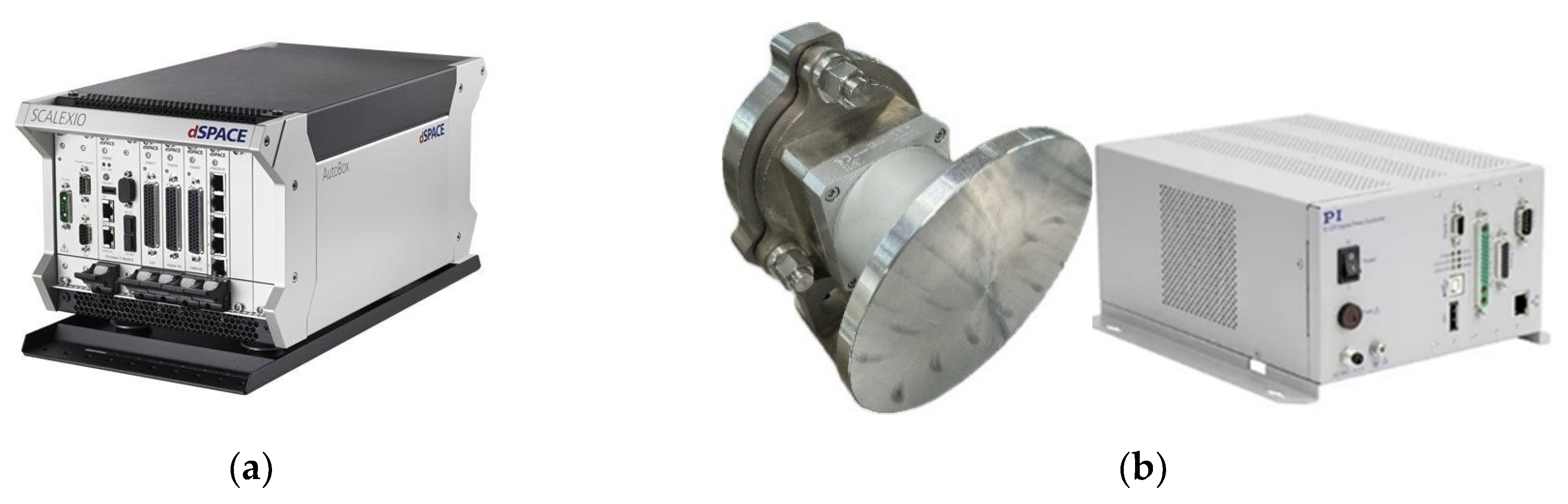
Figure 3.
Open-loop transfer function of proportional integral (PI) controller in FSM control system.
Figure 3.
Open-loop transfer function of proportional integral (PI) controller in FSM control system.
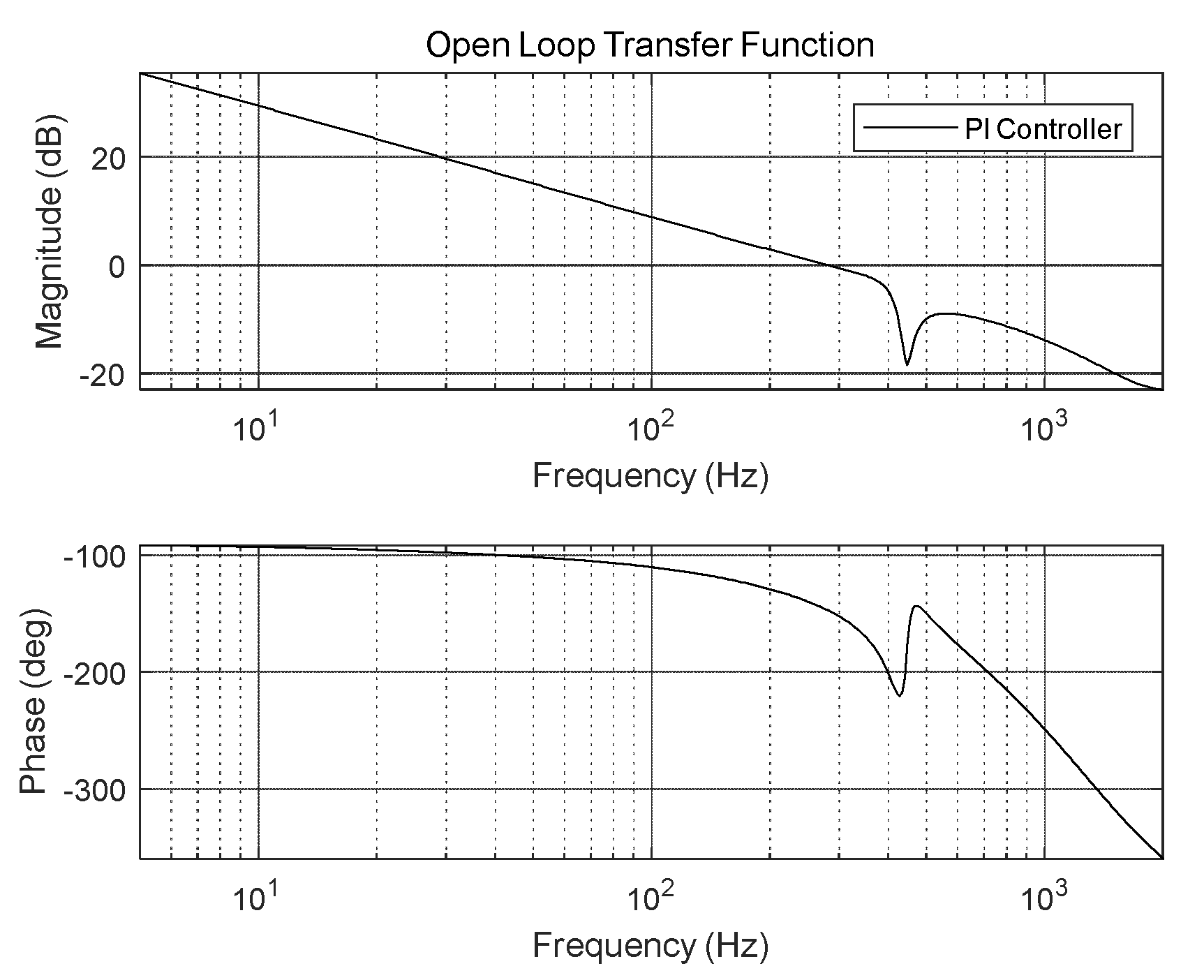
Figure 4.
Disturbance-rejection performance of FSM control system.
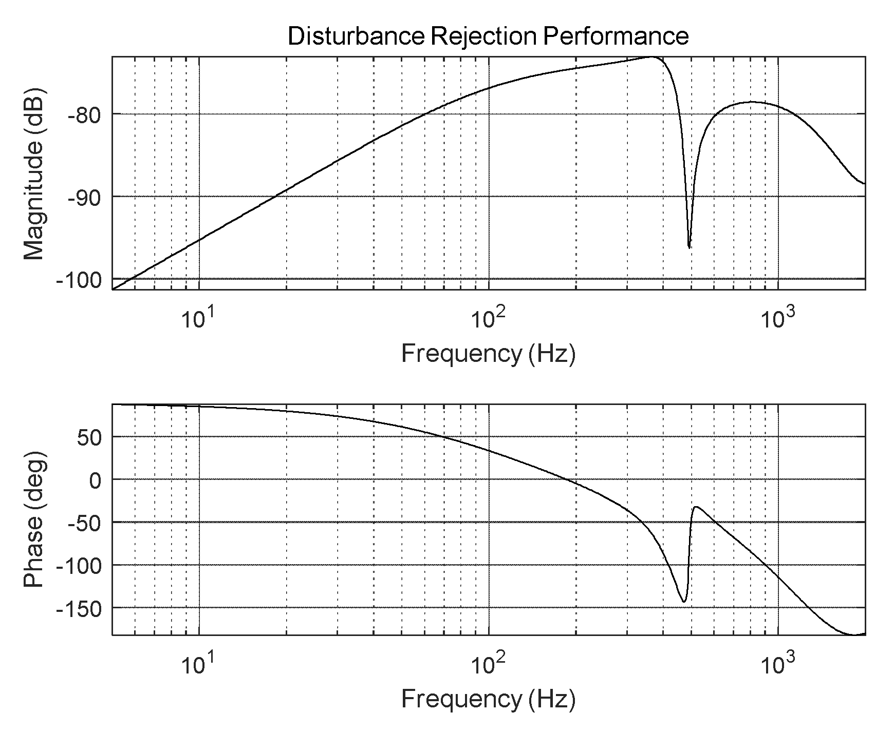
Figure 5.
Disturbance-rejection performance of FSM control system.
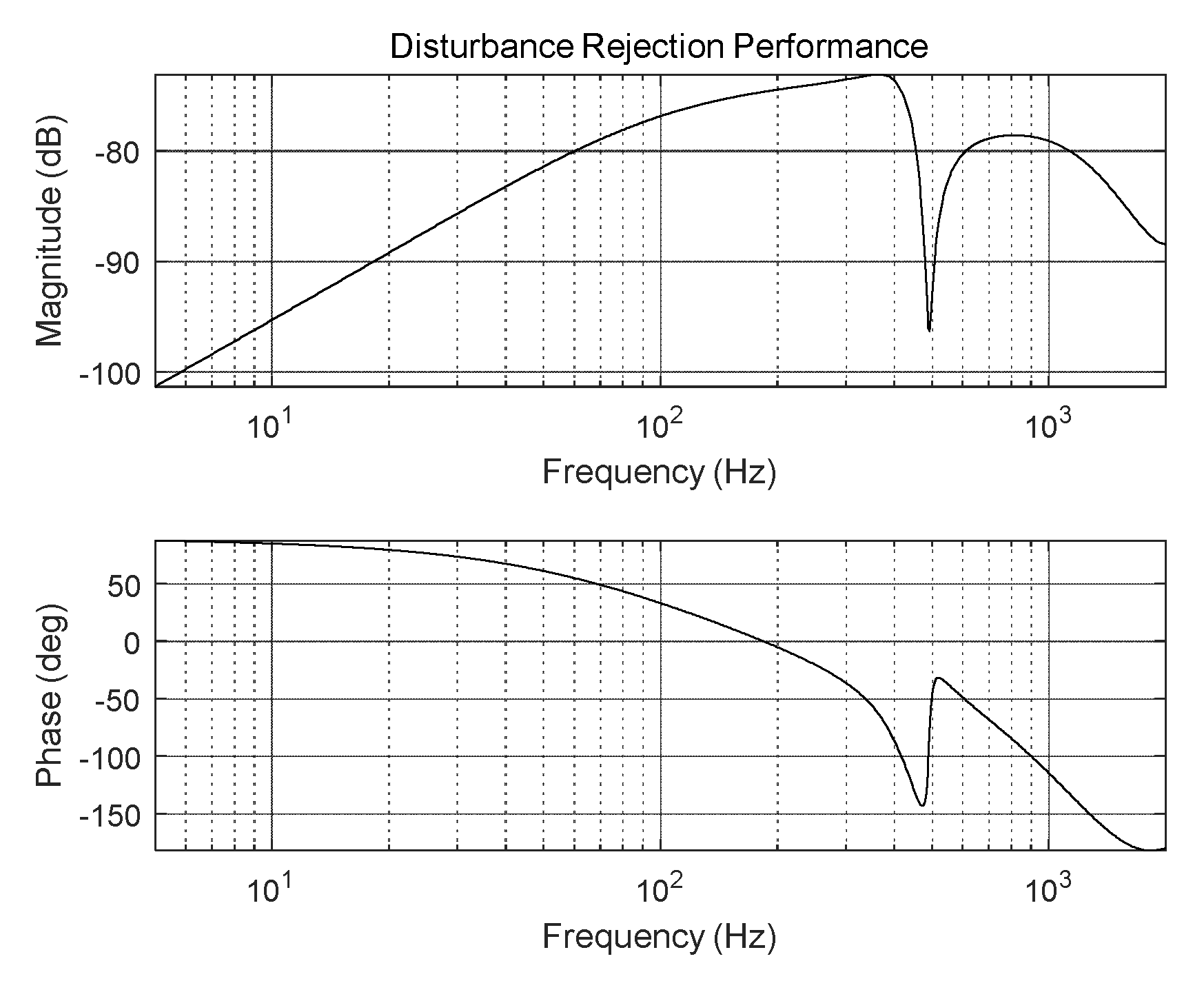
Figure 6.
Disturbance-rejection performance of FSM control system.
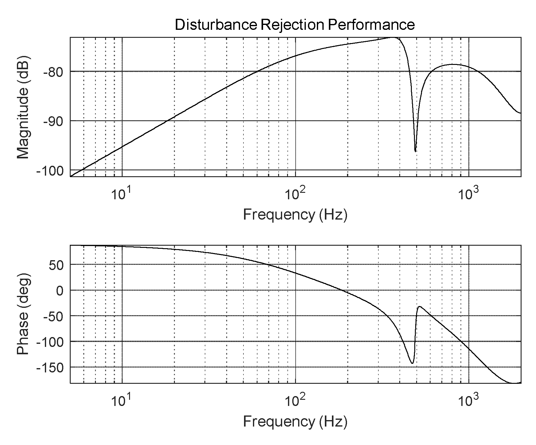
Figure 7.
Open-loop transfer function of IMP-based controller (at 60 and 65 Hz).
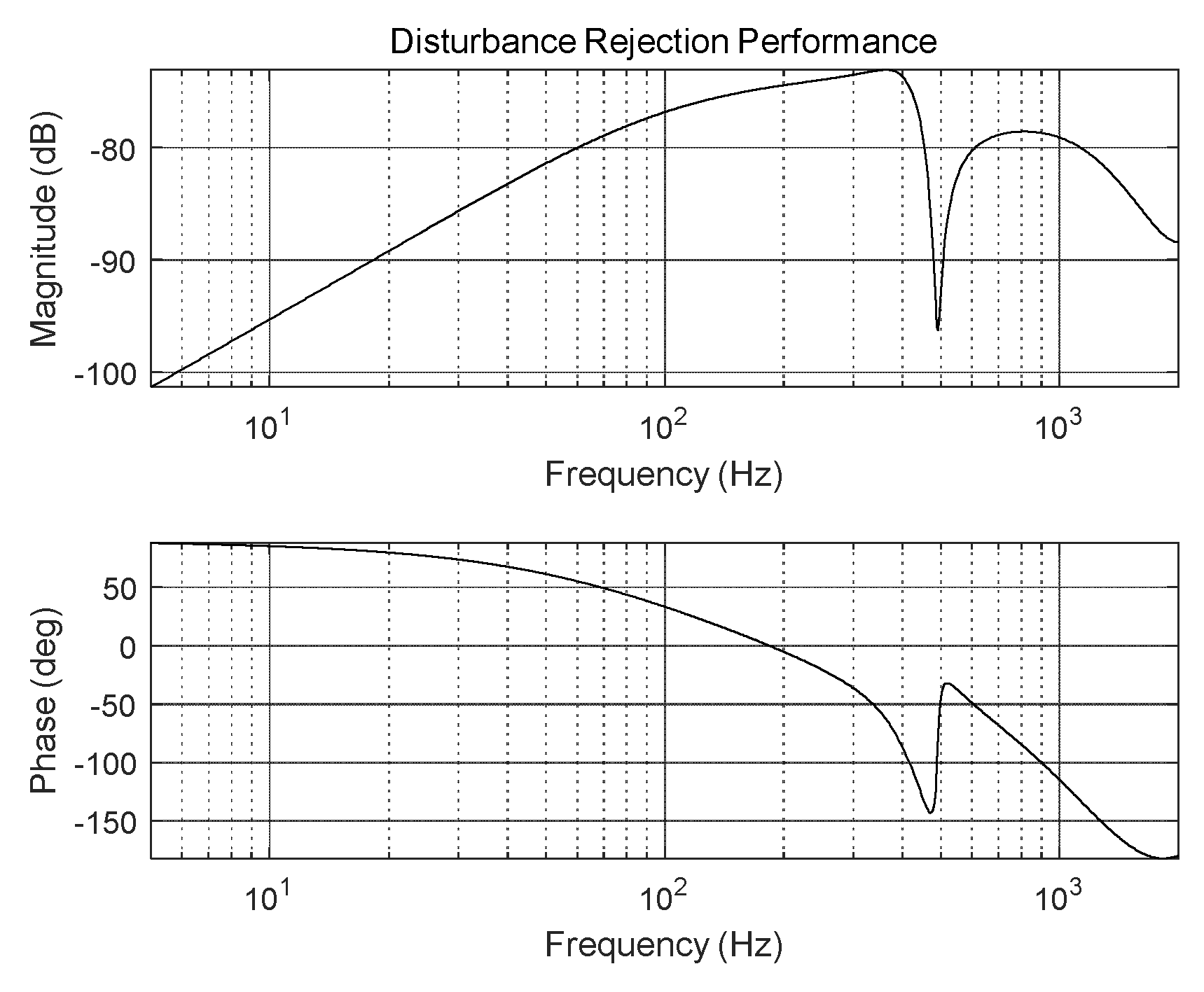
Figure 8.
Open-loop transfer function of IMP-based controller (at 60 and 71 Hz).
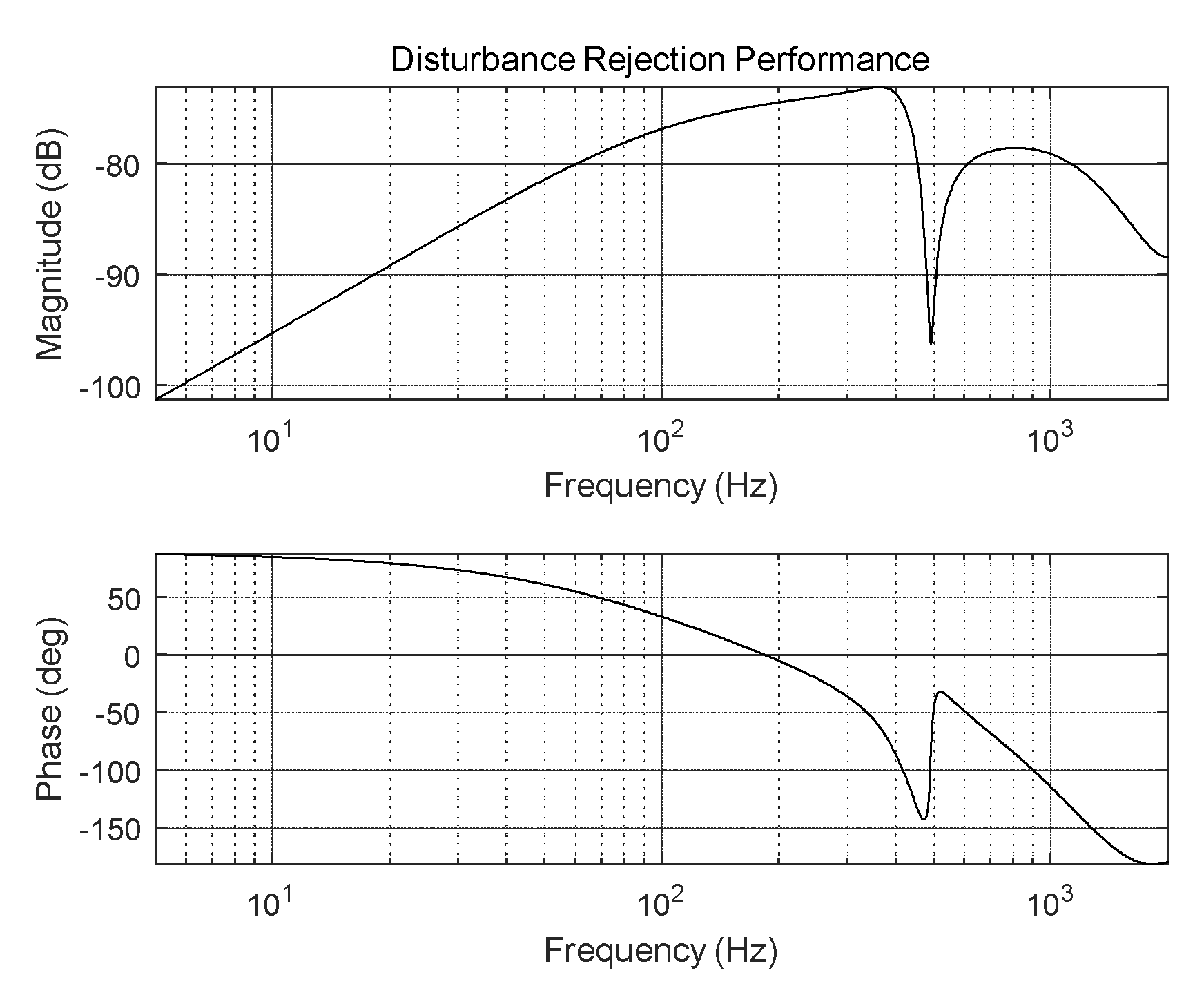
Figure 9.
Experimental results of FSM control system: (a) IMP (at 60 and 65 Hz), and (b) IMP (at 60 and 71 Hz).
Figure 9.
Experimental results of FSM control system: (a) IMP (at 60 and 65 Hz), and (b) IMP (at 60 and 71 Hz).
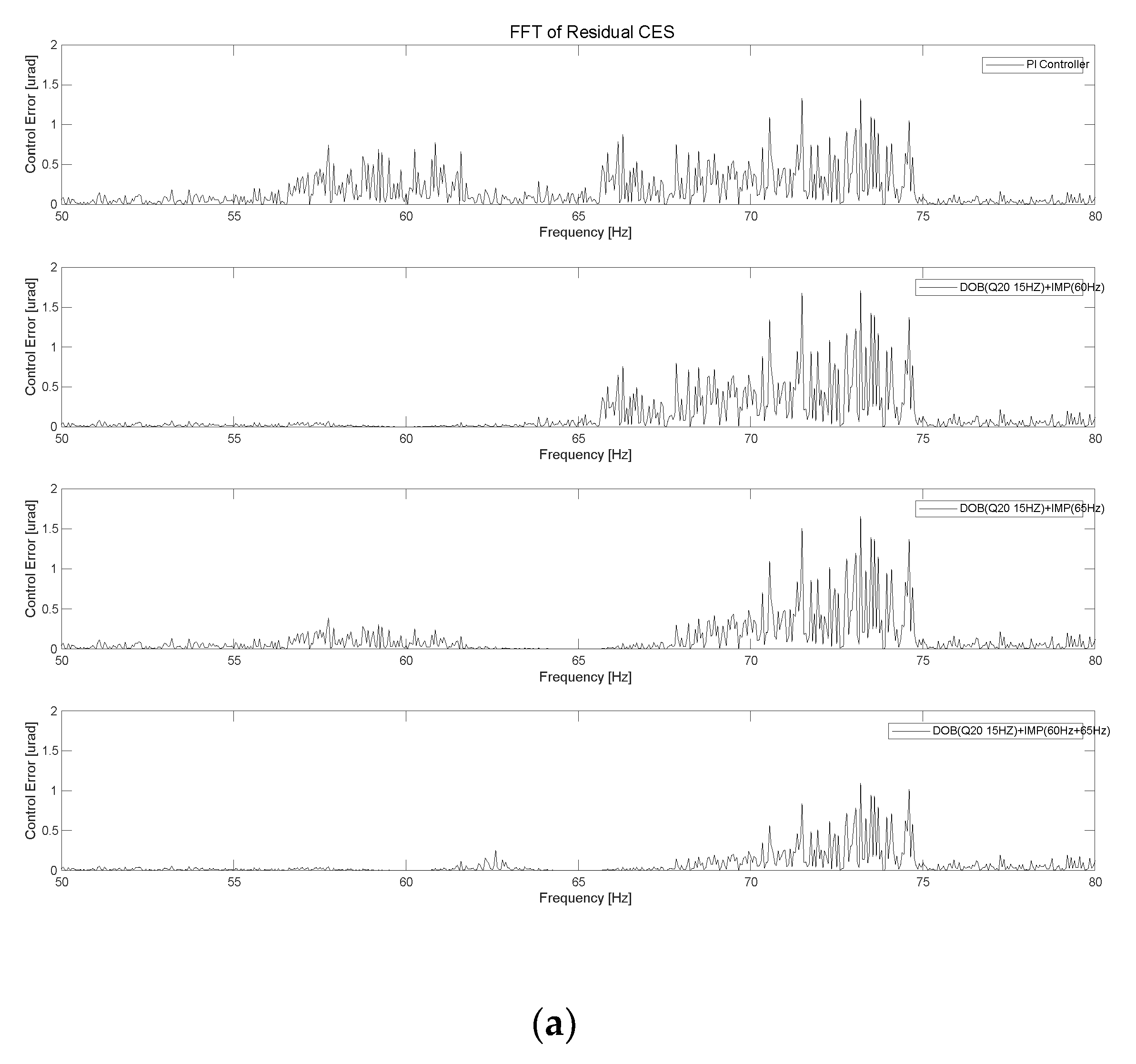
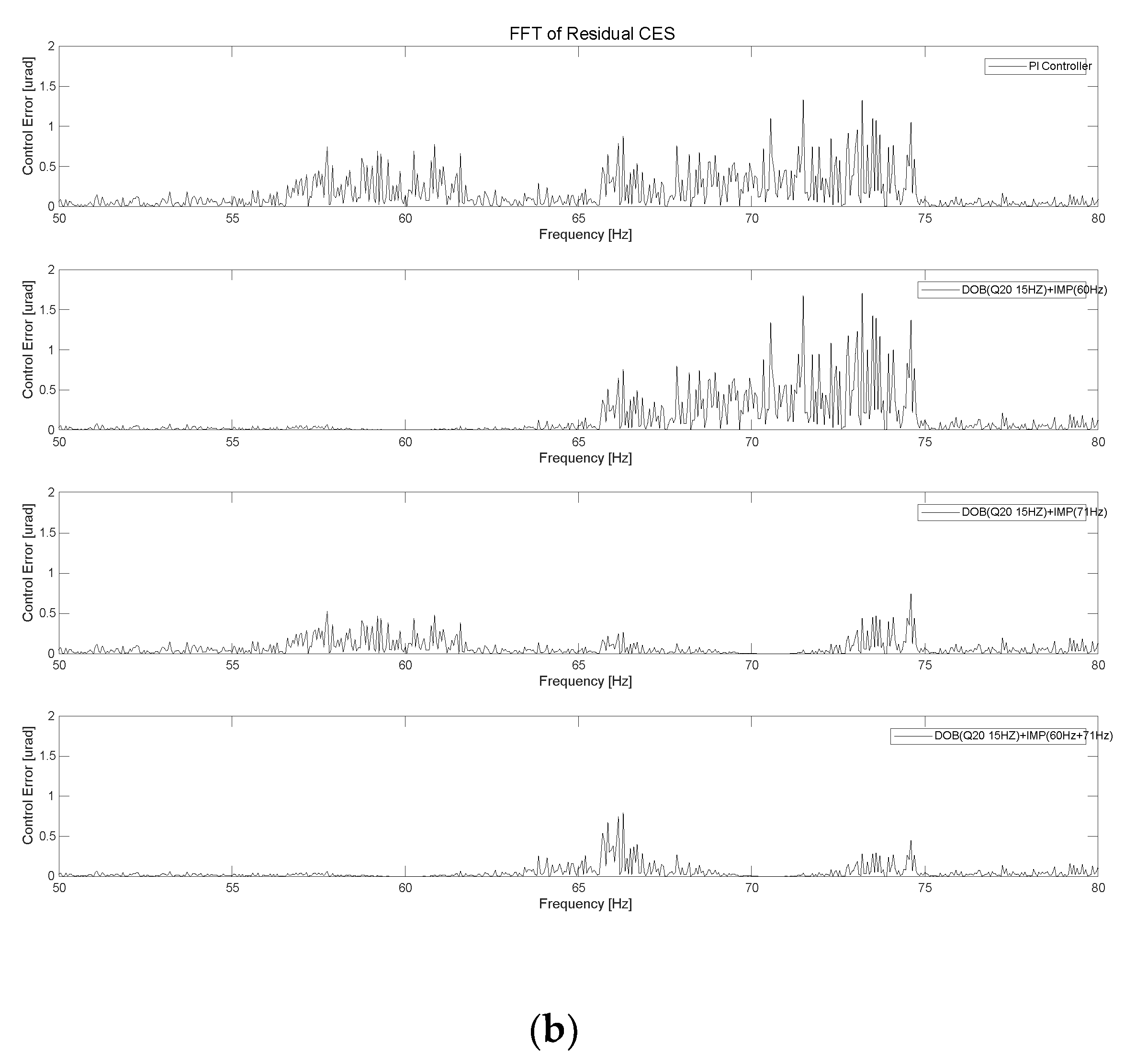
Figure 10.
Schematic diagram of FSM control system using IMP-based controller with DOB.
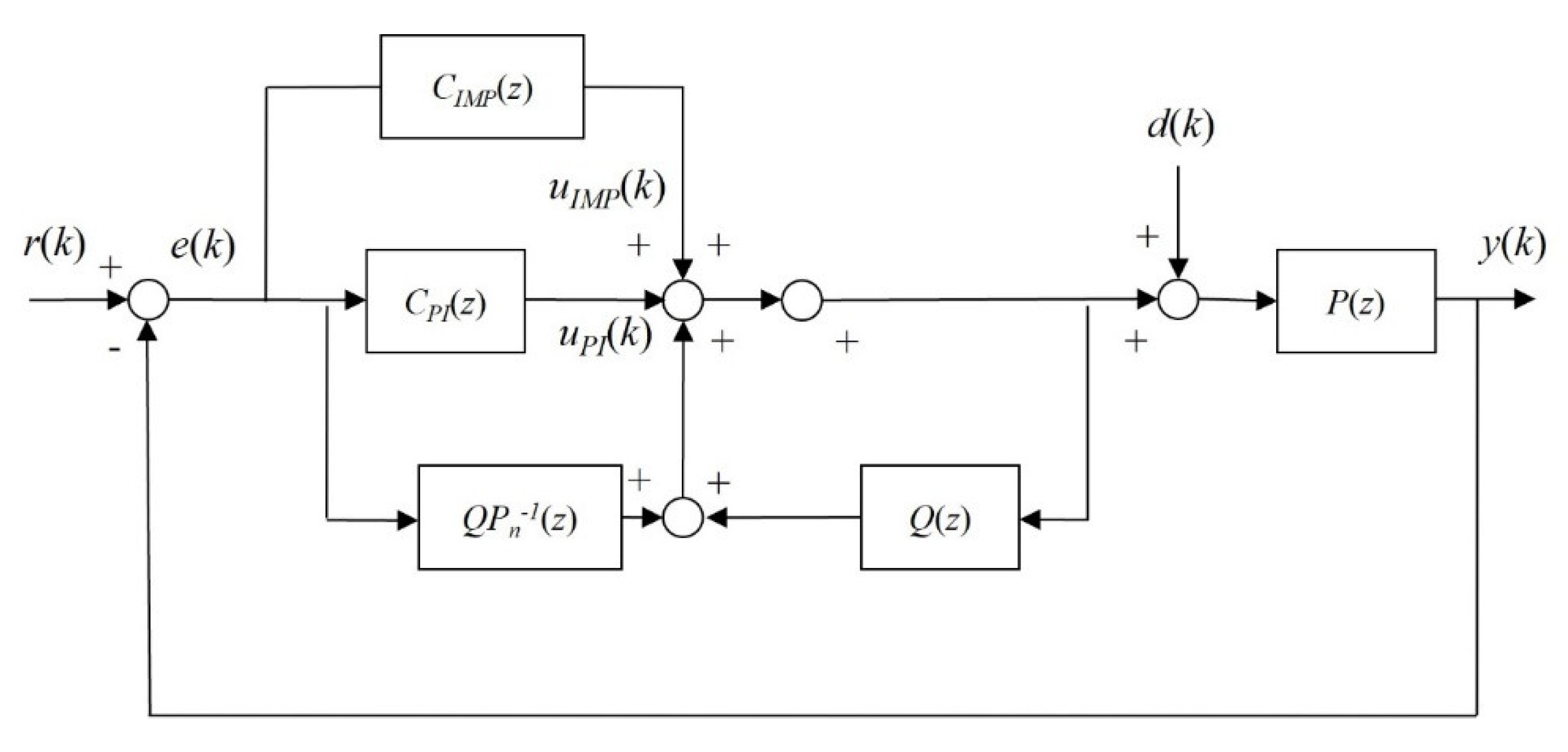
Figure 11.
Open-loop transfer function Q filter for FSM control system: (a) Q20, and (b) Q30.
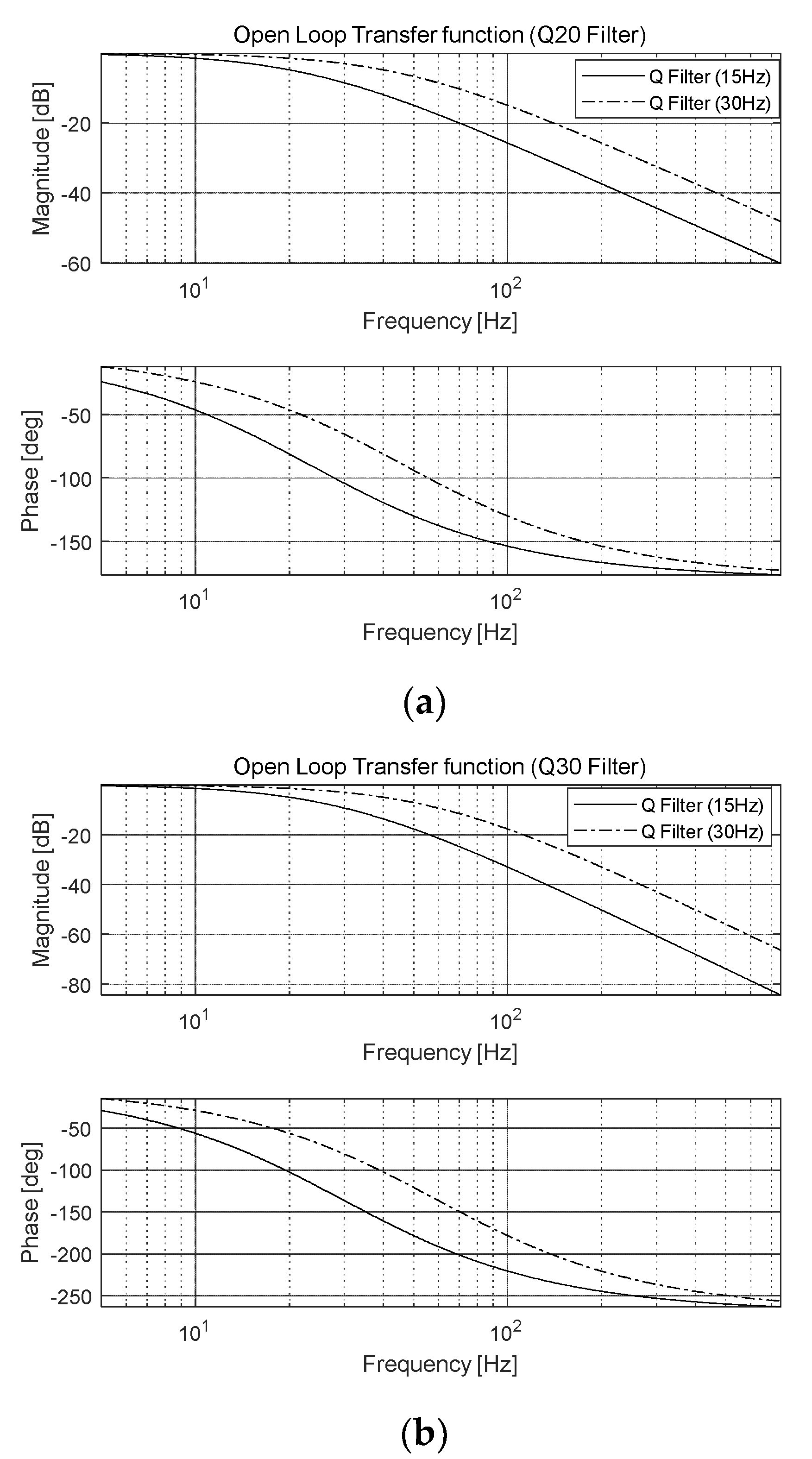
Figure 12.
Open-loop transfer function of IMP-based controller (at 60 and 65 Hz) with DOB (Q20 filter).
Figure 12.
Open-loop transfer function of IMP-based controller (at 60 and 65 Hz) with DOB (Q20 filter).

Figure 13.
Open-loop transfer function of IMP-based controller (at 60 and 65 Hz) with DOB (Q30 filter).
Figure 13.
Open-loop transfer function of IMP-based controller (at 60 and 65 Hz) with DOB (Q30 filter).
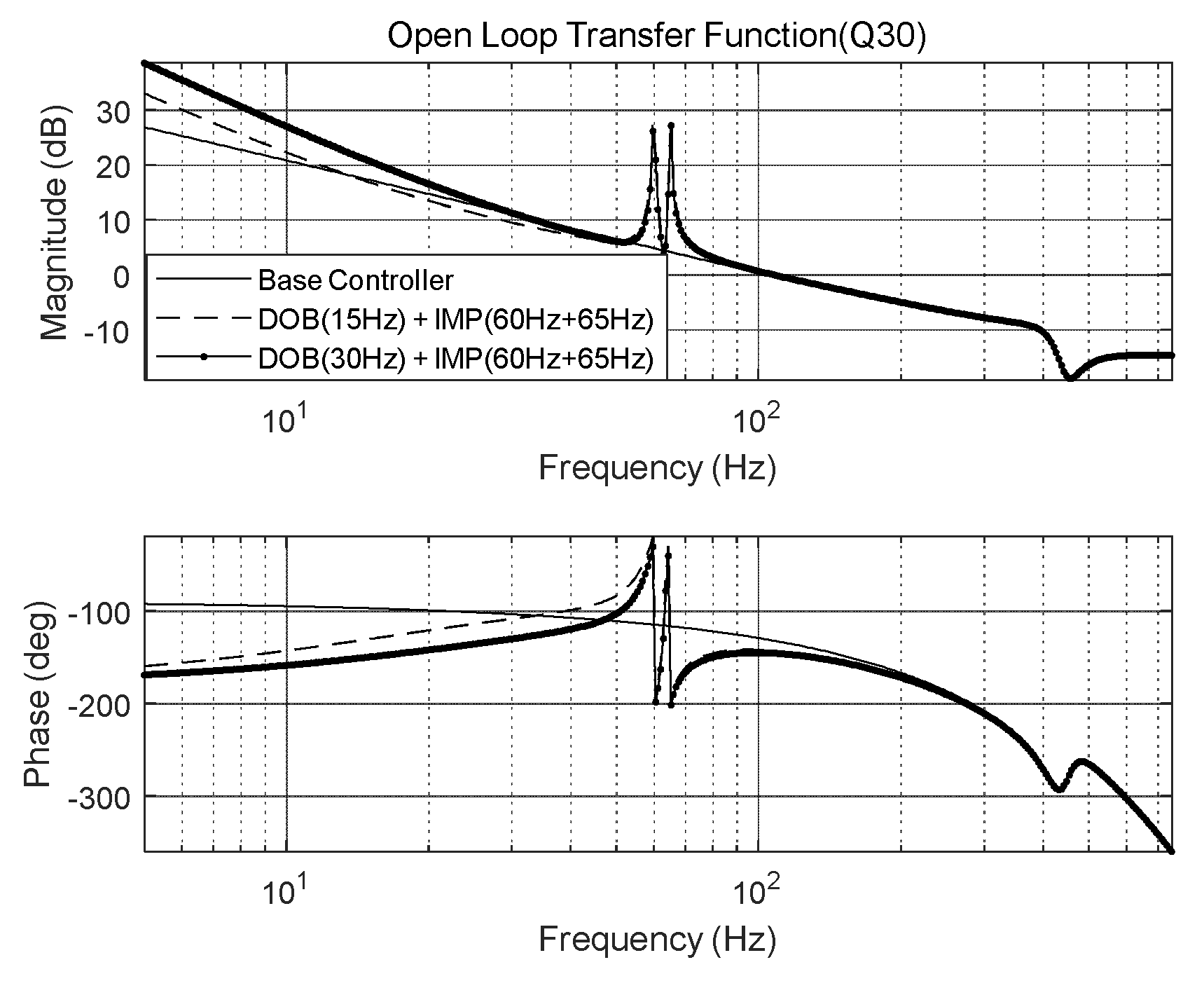
Figure 14.
Open-loop transfer function of IMP-based controller (at 60 and 71 Hz) with DOB (Q20 filter).
Figure 14.
Open-loop transfer function of IMP-based controller (at 60 and 71 Hz) with DOB (Q20 filter).
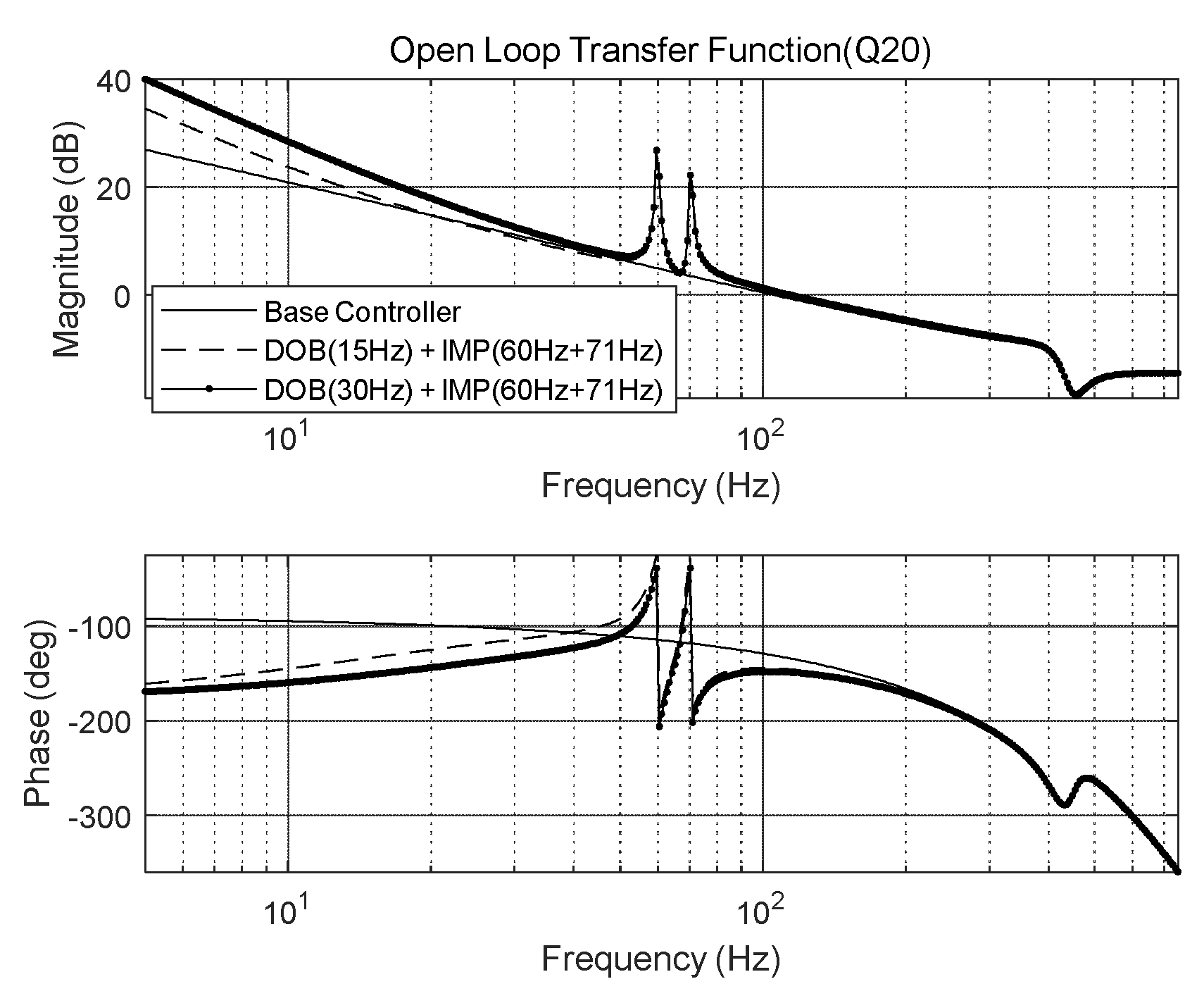
Figure 15.
Open-loop transfer function of IMP-based controller (at 60 and 71 Hz) with DOB (Q30 filter).
Figure 15.
Open-loop transfer function of IMP-based controller (at 60 and 71 Hz) with DOB (Q30 filter).
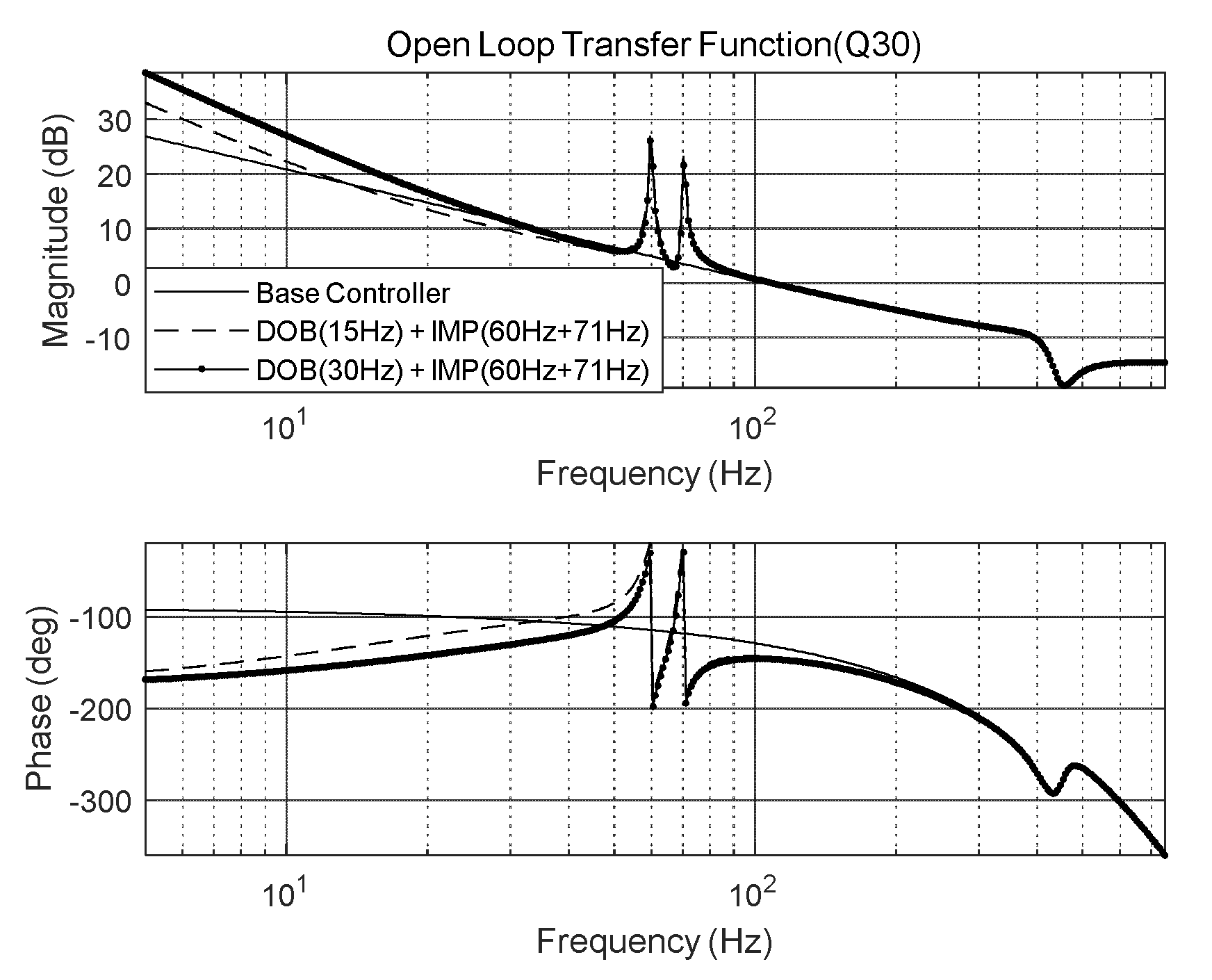
Figure 16.
Experimental results of FSM control system when using IMP with DOB: (a) Q20 (15 Hz), (b) Q20 (30 Hz), (c) Q30 (15 Hz), and (d) Q30 (30 Hz).
Figure 16.
Experimental results of FSM control system when using IMP with DOB: (a) Q20 (15 Hz), (b) Q20 (30 Hz), (c) Q30 (15 Hz), and (d) Q30 (30 Hz).
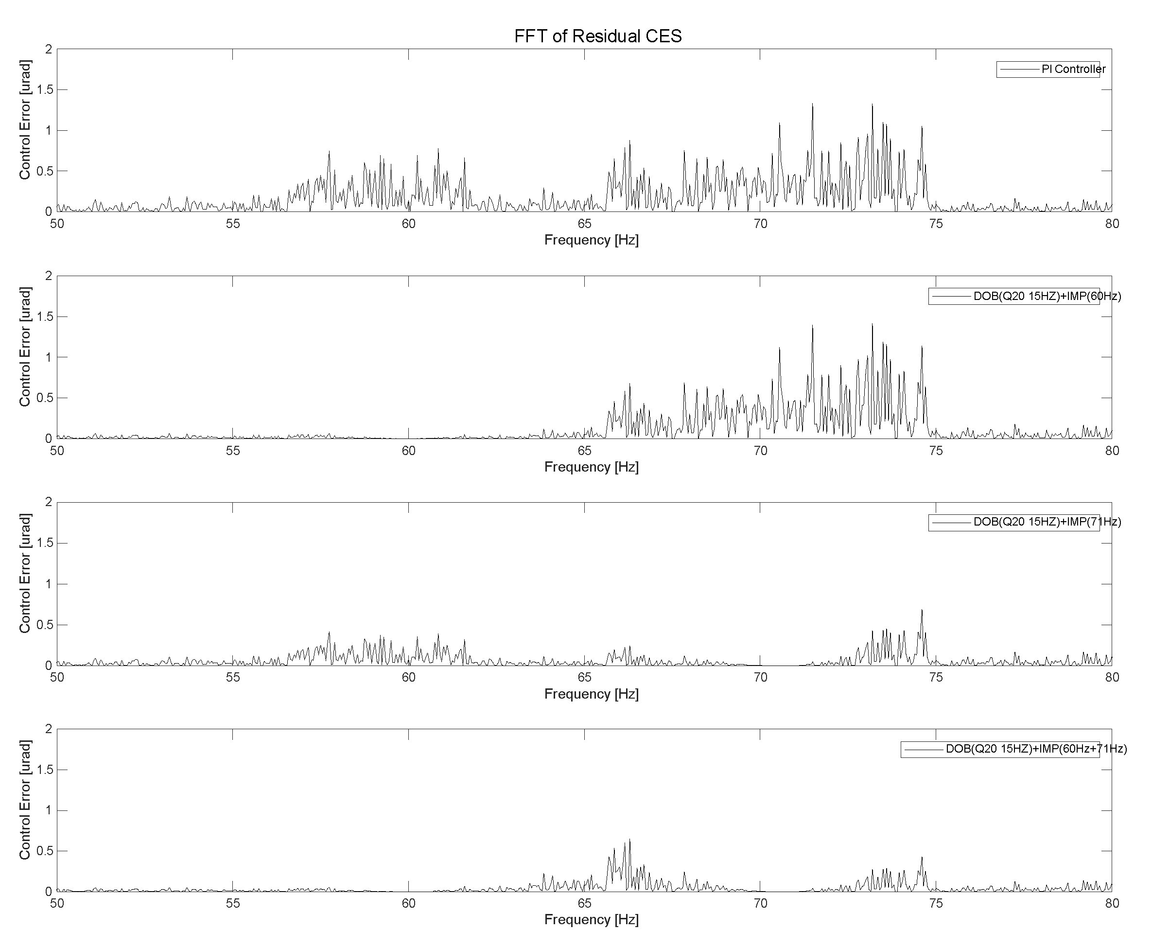
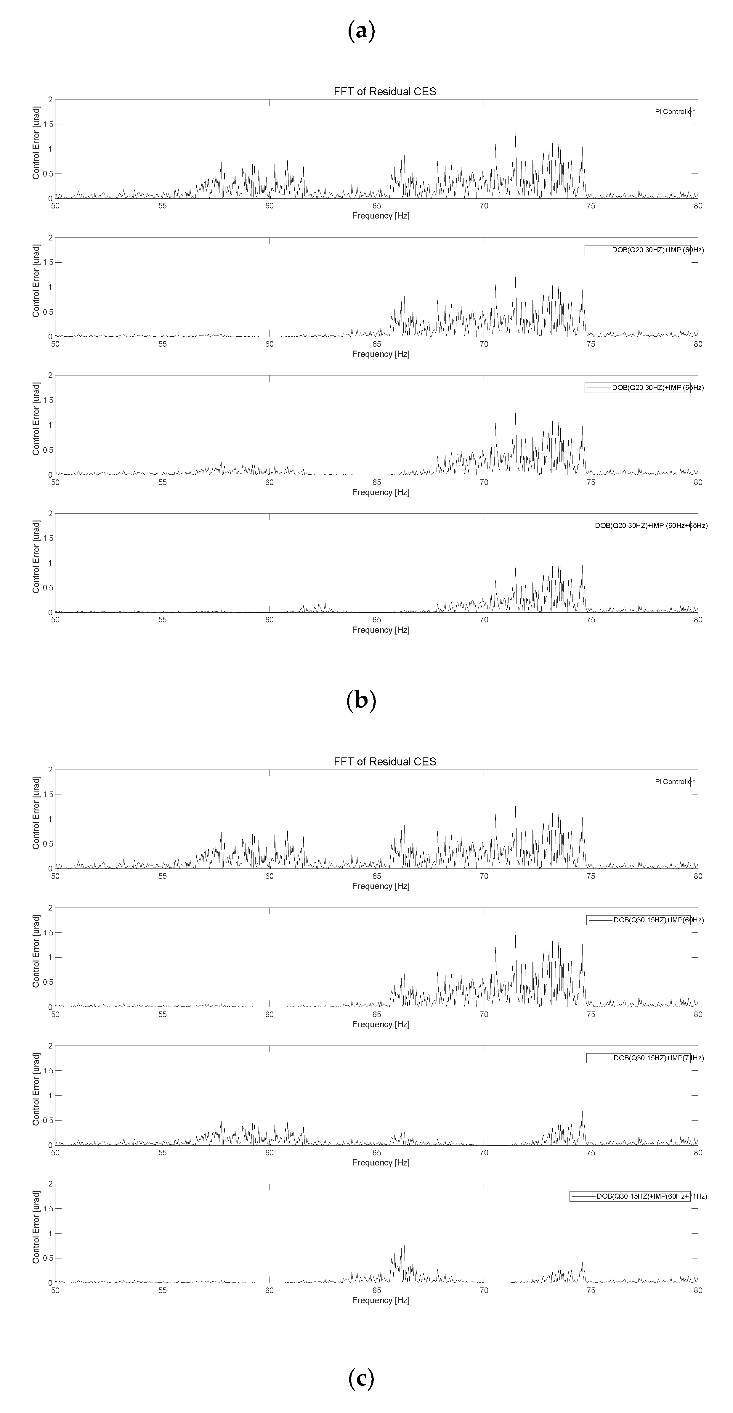
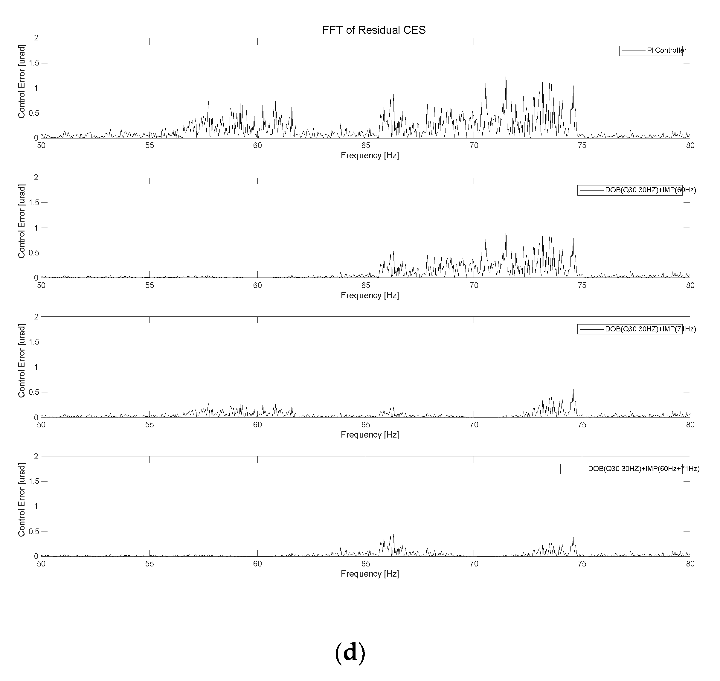

Table 1.
This is a table. Tables should be placed in the main text near to the first time they are cited.
Table 1.
This is a table. Tables should be placed in the main text near to the first time they are cited.
| Specification | Value |
|---|---|
| Resonance frequency | 450.2 Hz |
| 5 Hz sensitivity | 168.3 µrad /V |
| Gain of voltage amplifier | 10 V/V |
| Gain of sensor amplifier | 0.0059 V/ µrad |
Table 3.
Overall experimental results of FSM control system using IMP.
| Specification | PI controller |
IMP (60 Hz) |
IMP (65 Hz) |
IMP (71 Hz) |
IMP (60/65 Hz) |
IMP (60/71 Hz) |
|
|---|---|---|---|---|---|---|---|
| Only IMP |
Control error (μrad rms) |
7.97 | 7.43 | 7.17 | 6.05 | 6.00 | 5.41 |
Table 3.
Overall experimental results of FSM control system using IMP with and without DOB.
| Specification | PI controller |
IMP (60 Hz) |
IMP (65 Hz) |
IMP (71 Hz) |
IMP (60/65 Hz) |
IMP (60/71 Hz) |
|
|---|---|---|---|---|---|---|---|
| Only IMP |
Control error (μrad rms) |
7.97 | 7.43 | 7.17 | 6.05 | 6.00 | 5.41 |
|
Q20 filter (15 Hz) |
6.96 | 6.75 | 5.73 | 5.51 | 5.21 | ||
|
Q20 filter (30 Hz) |
6.76 | 6.57 | 5.51 | 5.57 | 5.06 | ||
|
Q30 filter (15 Hz) |
6.49 | 6.28 | 5.36 | 5.04 | 4.82 | ||
|
Q30 filter (30 Hz) |
6.18 | 6.05 | 5.24 | 5.12 | 4.84 | ||
Disclaimer/Publisher’s Note: The statements, opinions and data contained in all publications are solely those of the individual author(s) and contributor(s) and not of MDPI and/or the editor(s). MDPI and/or the editor(s) disclaim responsibility for any injury to people or property resulting from any ideas, methods, instructions or products referred to in the content. |
© 2024 by the authors. Licensee MDPI, Basel, Switzerland. This article is an open access article distributed under the terms and conditions of the Creative Commons Attribution (CC BY) license (http://creativecommons.org/licenses/by/4.0/).
Copyright: This open access article is published under a Creative Commons CC BY 4.0 license, which permit the free download, distribution, and reuse, provided that the author and preprint are cited in any reuse.


