

Submitted:
15 April 2024
Posted:
17 April 2024
You are already at the latest version
Abstract
Electrification of society, increasing renewable energy sources and mobility charging lead to new loading patterns for power transformers. Dynamic load conditions induce enhanced mechanical stress on the transformers’ windings, potentially causing degradation of the solid insulation over time and compromising the transformer's short-circuit withstand capability. Thermal expansion of the windings, caused by losses in the copper conductors, occurring as the transformer is load-ed, increases the stress. Conversely, magnetic losses in the core and tie plate expansion contribute to a reduction in stress. This paper presents the effect of step changes in core losses and copper losses by on-line measurements of the clamping pressure, to better understand the mechanical stresses acting upon the solid insulation cellulose materials.
Keywords:
Power transformer
; clamping pressure
; transformer energisation
; transformer loading
; short-circuit performance
; on-line measurements
1. Introduction
Transformers are cornerstones of the electric production and distribution system, enabling transmission of electric power while minimising losses, by shifting the voltage levels. Electric power typically passes through 4-5 transformers on the route from producer to consumer. Sufficient winding clamping pressure is required for the transformer to resist the strong forces arising from through-current faults, and is therefore essential for the short-circuit performance of a power transformer [1]. Transformer failure is a rare event, but it has been reported that more than one in four failures were due to short circuit events [2].
The main function of a power transformer is achieved by having conductors, coiled in windings, wound around a magnetic core. The conductors in the windings are electrically insulated, typically by resin and paper. An electrically insulating liquid is used to cool the windings by transporting heat, and this heat is removed by a heat exchange, typically radiators, on the outside of the transformer tank. The liquid insulation also has an impregnation function on the solid insulation, protecting it and slowing degradation processes. To allow for liquid flow within the windings, pressboard spacers are used to create ducts for liquid flow. The windings are clamped together, compressing the conductors and the solid insulation (cellulose) to the design-required clamping pressure, to ensure the mechanical integrity of the system, which shall resist electric and magnetic forces acting upon the windings.
On short time scales, the winding clamping pressure will vary following the thermal expansion and contraction of the various parts of the clamping system. On longer time scales, changes in humidity and aging of cellulose materials will change their stiffness and will thus affect the clamping pressure [3,4,5]. New transformer loading patterns, caused by the integration of renewable energy production and mobility charging, subject the insulation materials to more rapid thermal and mechanical stresses. The effect this may have on the long-term clamping pressure is not well understood.
The integrity of the windings and of the clamping structure can be assessed indirectly through electrical (frequency response analysis) [6] or mechanical (vibrational analysis) measurements. However, novel sensors also allow for quantitative measurements, directly on the clamping system [7]. The interpretation of these on-line measurements can be used for condition-based maintenance. Many parameters and effects can impact a transformers’ winding stability, which are not discussed in this article, as for example: the sizing (pre-drying of coils under pressure in the factory), the clamping pressure of the winding per se, moisture increase in operation and related insulation swelling, moisture migration between solid and liquid insulation, and decomposition of cellulosic insulation because of aging. This paper presents winding clamping pressure and temperature variations on-line measurements from a recently commissioned new power transformer. Particularly, step changes of loading with and without prior energisation are reported.
2. Materials and Methods
Traditionally, transformers can be equipped with sensors to monitor the loading, ambient temperature, and top oil temperature. Monitoring of the winding hot spot temperature is often included, as this is the critical temperature for aging of the paper in the windings [8]. Such sensors are commonly fibre optic types, since high electric and magnetic fields in the windings exclude many types of sensors.
A 40 MVA substation transformer (T3) placed in south-eastern part of Norway, see Figure 1. The cooling system of the T3 is of ONAN type, i.e., heat exchange between the oil and the windings through natural convection, and heat exchange between the oil and the ambient air, also through natural convection. The transformer T3 is equipped with sensors for measuring the clamping pressure on-line (fibre Bragg grating), as well as with several temperature sensors (fibre GaAs type) in the windings, see Figure 2. There are fibre-optic temperature sensors for the hot spot and in the middle of both the helix LV- and disc-type HV-windings, as well as for oil temperature into and out of the windings. The temperatures at outlet to, and inlet from, one radiator are also measured. In addition there is a resistive temperature sensor (Pt100) for top oil temperature and the ambient temperature is measured some distance below the radiators.
The transformer clamping system consists of top and bottom clamping beams, connected by tie plates mounted along the core legs, see Figure 2. The windings, the laminated wooden blocks and plates, and the insulation materials are compressed between these beams. The purpose of the clamping system is to maintain sufficient pressure on the windings to keep the turns/discs/conductors in place. The initial clamping pressure is set during the final stages of fabrication. This is typically achieved by jacking up the winding stack to a high pressure and adjusting the height of the top blocks to fit, such that the designed pressure remains after removing the jacks.
There are eight clamping pressure sensors installed on the leg of the central phase. These are located on top of the upper winding plate, and underneath the wooden insulation blocks positioned below the steel clamping beams, see Figure 2. The pressure measurements presented in this paper is the average of the seven sensors still in function. Clamping pressure act to compress the sensor unit which leads to strain that can be measured. The clamping pressure sensor unit consists of a temperature sensor and a strain sensor, both on the same fibre. The operating principle of fibre Bragg grating sensors is that the grating acts as a dielectric mirror, for a frequency given by the grating distance. As such, the grating distance can be measured by sending a wide frequency wave package into the fibre, and then measuring the peak frequency of the reflected wave. Mechanical strain and thermal expansion change the grating distance, and thus the reflected frequency. The sensors are calibrated by fitting a third-order polynomial for both the temperature and the mechanical strain sensor. Importantly, the temperature measurement is used to compensate for temperature expansion of the strain sensor when calculating the pressure. The operational details of the sensors and measurements from the transformer heat run test were presented earlier [7].
Steel (the tie plates), copper (the windings), and insulation materials (wood, paper, and pressboard) have different mechanical and thermal properties. Thermal expansion coefficients are typically 12⋅10-6/K, 17⋅10-6/K, 70⋅10-6/K, for steel, copper, and pressboard (out of plane), respectively. The insulation materials are much softer and have a higher thermal expansion coefficient than the metals. Increasing the temperature will cause expansion of all the parts, but less for the steel tie plates than the windings, increasing the tensile stress in the tie plates and the compressive stress in the windings. The higher thermal expansion of copper than steel adds to this, but the major effect is the difference between the pressboard and the steel. Conversely, cooling the entire system will reduce the pressure in the clamping system. In general, the system is not in thermal equilibrium, neither during normal operation, nor following step changes. The varying temperature throughout the system will influence thermal expansion of the windings and clamping system, which in turn affects the clamping pressure.
Energising the transformer is done by connecting the HV windings, which magnetises the core. Magnetic losses in the core cause core heating, affecting the tie plates placed along the core legs. The subsequent thermal expansion of the tie plates will reduce the clamping pressure. Core heating affects the temperature of the transformer as a whole, but the tie plates more directly than the windings. On the other hand, when loading the transformer, current flows through the windings, and copper losses heat the conductors, and in turn the paper, pressboard, and insulation liquid. This affects the windings more directly than the tie plates and will increase the clamping pressure.
The transformer (T3) is placed in the grid, as one of two in a newly constructed substation. This is a typical configuration, following the “N-1” requirement to be able to supply power, even with one transformer failing. The configuration also enables the shifting of load between them, see Figure 3. Loading and unloading T3 is done by operating the low voltage circuit breaker (CB-18T3), while the high voltage circuit breaker (CB-132T3) is closed. Energising and de-energising T3 is done by operating the high voltage circuit breaker (CB-132T3), while the low voltage circuit breaker (CB-18T3) is open.
A step loading programme of T3 can be performed as follows:
- Resting time. Keep the transformer T3 de-energised and unloaded while T1 takes all load of the substation.
- Energise T3 by connecting the high voltage side (CB-132T3).
- Share load between T1 and T3 by connecting the low voltage side (CB-18T3).
- Disconnect the low voltage side of T1 (CB-18T1) such that T3 takes all the load.
- Stabilisation time. Keep the transformer energised and loaded.
The operations 1-3, or the reverse, can be done within a minute. The result is a step increase in load for T3, from a resting unloaded condition, to taking all the load of the substation. A series of such operations was performed in February 2023, see Figure 4.
The scheme of operations for transformer T3 was as follows:
- O1: De-energise after resting without load for one day.
- O2: Energise and load, one day after O1.
- O3: Unload and de-energise, two days after O2.
- O4: Energise, one day after O3.
- O5: Load, one day after O4.
- O6: Unload and de-energise, two days after O5.
- O7: Energise and load, two days after O6.
- O8: Unload and de-energise, one day after O7.
The main goal of the experiment was to investigate the clamping pressure dynamics while loading and unloading the transformer. The scheme was designed such that the influence of energisation (core losses) can be separated from loading (copper losses). The different operations were performed at intervals of one to two days, to allow the system some time to equilibrate between the operations. The substation is constructed for the future, having a low loading for now, reaching about 60 % of nominal during the heavy loading in winter times. The maximum load obtained for T3 during the experimental period presented in this this paper was about 50 % of rated power.
3. Results
A series of operations was performed in February 2023, from which a selection is shown in Figure 4. The operations consist in loading/unloading and energising/de-energising the transformer. The figure shows how energisation and loading influenced the LV hot spot temperature, the top oil temperature, and the clamping pressure. The losses are 16 kW the core (no load losses) and 120 kW for the windings at rated power. For a loading of 15 MVA (37.5 % of rated power), the core and copper losses will be comparable, while at 20 MVA (50 % of rated power) the copper losses will be the double of the core losses. As such, at low loads, the core losses contribute significantly to the total produced heat, and thus to the temperature rise of the transformer. Energisation (O4) and de-energisation (O1) had a significant influence on the clamping pressure, yielding about a 20 % change. During normal operation, e.g., the days after O2 or O5, the clamping pressure followed the trend of the loading, see Figure 4. This is due to load and associated winding temperature variation, causing thermal expansion and contraction effects on the clamped windings. The ambient temperature was rather low but stable, within the range from -2 °C to 8 °C, throughout the period of 11 days.
Figure 5 shows the operations O5 and O7, applying a step load from zero to about half the rated power. In both cases, the hot spot temperature increased almost linearly in the beginning, before approaching an exponential behaviour, and then flattening out. One may argue on whether the response is linear for the first part, or whether this is just the beginning of an exponential curve. However, for the first part of the graphs, the temperature out to the radiator does not change, implying that the oil temperature from the radiator, the bottom oil, and the oil into the windings does not change either. The thermal siphon through the windings is not yet properly active, and as long as that is the case, the heating is close to linear. The response was somewhat flatter for O5 than O7, but with prior energisation, the oil started at a higher temperature and the hot spot increase was also somewhat higher. In both cases, there was a delay before the temperature of the oil to the radiator increased. The initial level for the radiator temperature was much higher for O5, while the delayed increase was more prominent for O7. Oil circulation was not developed in the windings during the unloaded state and will take some time to develop once loading was applied. The temperature of the hot spot was expected to increase linearly until the flow was developed, and then exponentially when the thermal siphon was active, and oil cooled the windings. There will be a further delay for the hot oil to reach the radiators, which also depends on whether the flow in the radiators was already developed (previous energisation) or not (from de-energised). The time to develop the flow is expected to depend on the loading and losses. The initial linear rise was indeed steeper and shorter for the heat run test performed as part of the factory acceptance testing [7].
The difference in clamping pressure between O5 and O7 in Figure 5, leading from energised and de-energised, respectively, was profound. For O5, it increased with the increasing winding temperature, as expected. However, O7 showed a clamping pressure having a higher initial value, briefly dropping as the transformer was energised, then increasing for some time while the windings warmed, but thereafter reducing in value. The reduction seemingly corresponded to the heating of the oil, as evident by the temperature out to the radiator. The initial pressure drop O7 was an instantaneous reduction of about 0.03 MPa. Instantaneous, that is, from one second to the next, as the sensors readings were recorded once per second. This reduction was likely caused by magnetic forces compressing the windings, causing a reduction of pressure in the clamping system. The magnitude of the reduction is somewhat distorted in Figure 5, since the data presented there are averaged minute for minute.
Energisation and de-energisation caused the clamping pressure to change over the course of several hours, presumably following heating and cooling, respectively, of the tie plates and the core. The brief, instantaneous reduction in pressure when energising and loading, was quickly dwarfed by the increase in pressure following the heating of the windings, see Figure 5. However, over the course of some hours, the pressure was again reduced as the transformer and clamping structure warmed up. Removing the load had a similar, but inverse effect, where the cooling of the windings initially reduced the pressure, but cooling of the tie plates, quickly counteracted this, when the transformer was also de-energised.
The effect of core losses (heating) on the clamping structure can be separated from copper losses (heating) by energising and de-energising the transformer under no-load conditions, see O1 and O4 shown in Figure 6. The latter, energisation in O4, showed an immediate drop in pressure, followed by a continued reduction. The response when energising and loading (O7), can be explained by superimposing energising (O4) and loading with prior energisation (O5). Interestingly, there was no sudden pressure change when de-energising (O1), just a continuous increase. In both cases, the oil temperature to the radiator changed, yet with significant delay in the case of energisation O4, see Figure 6. The change to the core temperature, and specifically to the tie plates, would be the main contributor to these pressure changes. It would have been beneficial for this study if these temperatures had been measured as well.
Removing load from the transformer is associated with cooling of the windings and the oil, as shown in Figure 7. Corresponding to Figure 5, the clamping pressure followed the hot spot temperature, when the energisation was maintained, see O5 and O8. However, when both the load was taken off and the energisation was not maintained (O6), the trend of the clamping pressure reflected a superposition of de-energising (O1) and removing the load (O8).
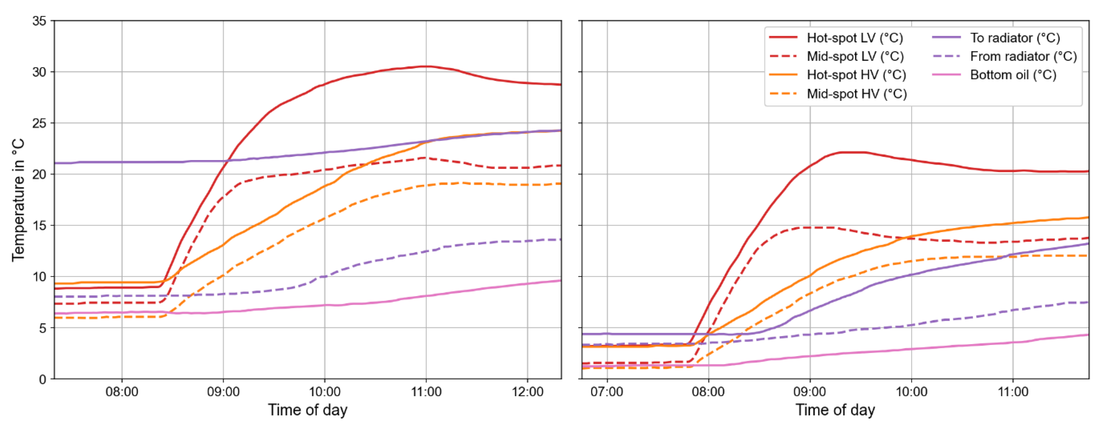
Figure 5 gives details on the effect on the clamping pressure when loading with (O5) and without (O7) prior energisation, while Figure 8 gives further details on the temperatures in the different parts of the transformer. For O7, all temperatures were between 0 °C and 5 °C. For O5, most temperatures were about 5 °C higher, expect the oil to the radiator, which differed significantly, exceeding 20 °C. In both cases, the windings warmed linearly initially, and there was a delay of about half an hour before the oil temperature to the radiator began to increase, with a change more prominent for the second case (O7). The mid-spot sensors stabilised faster and at a lower temperature than the hot spot sensors, while the temperature rise was much steeper and stabilised faster for LV than for HV. The difference between the mid-spot and the hot-spot sensors is an indication to how the thermal siphon develops and the time it takes before fresh oil from the bottom cool the windings. These findings are in line with expectations from the heat run test [7]. However, the heat run test was performed by the short circuit method, i.e., with very low core losses and copper losses exceeding nominal (compensating for no core losses). As such, there was a steeper temperature increase and a much higher increase in clamping pressure compared to this study.
5. Conclusions
In this study, thermal effects and interactions within the winding clamping system of a 40 MVA transformer are discussed, interpreting on-line pressure measurements during and after the step-events of energisation, loading, unloading, and de-energisation. The substation is newly constructed with a long term prospective of future loads, its utilisation is currently about 50 %, considering the N-1 requirement. As such, about 50 % of rated power is about the highest attainable for the transformer, but this is expected to increase in the future. Larger load changes are of further interest but were presently not possible.
The pressure in the clamping system varied with the thermal expansion of the windings and the tie plates. Under normal operation, the pressure varied mainly with the temperature of the windings. However, core energisation and subsequent heating of the tie plates also had a distinct impact on the clamping pressure. This was best demonstrated when the transformer was energised but not loaded. However, the effect of stopping or maintaining energisation was also visible when loading and unloading the transformer. Energising and loading, or unloading and de-energising, at the same time, reduced the fluctuations in the clamping pressure, contrary to loading and de-loading while keeping the transformer energised. How multiple pressure changes over time affect the solid insulation of a transformer is unknown at this stage. It is desirable to investigate the effects of step loading to higher loads, closer to nominal, if possible, in the future.
On-line monitoring of the clamping pressure can be a basis for future condition-based maintenance and is promising with regards to improving the security of energy supply by measuring a key indicator of the transformer’s short circuit performance. The integration of more renewable power sources and mobility charging in future will increase transformer loading changes. Monitoring can be a particular interested in applications where transformers are subjected to heavy and fluctuating loading. Better understanding the mechanical stress experienced by the cellulose materials during such conditions can support estimations of the remaining winding clamping force, indicating the remaining robustness against short-circuit stresses, and thus improve the operational safety.
Supplementary Materials
The following supporting information can be downloaded at the website of this paper posted on Preprints.org.
Author Contributions
IM performed the investigation, data curation, visualisation, and wrote the original draft. AM contributed with the resources. All authors contributed to conceptualisation, review and editing of the manuscript, and have read and agreed to the published version of the manuscript.
Funding
The work was supported by the DynaLoad project partners: Electricité de France (EDF), Elvia AS, Kolektor Etra, Siemens Energy, SP Energy Networks, Statkraft Energy, Statnett SF, and Weidmann Electrical Technology. DynaLoad is a Knowledge-building Project for Industry supported by The Research Council of Norway under the contract 319289. For more information, see https://prosjektbanken.forskningsradet.no/project/FORISS/319289.
Data Availability Statement
The data are available in the Supplementary Materials.
Acknowledgments
The authors are grateful to the technical personnel and control centre at Elvia who carried out the physical operations and compiled the sensor data, in particular Kjetil Kjølerbakken and Marius Johansen.
Conflicts of Interest
The authors declare no conflict of interest.
References
- CIGRE WG A2.37 TB 642 - Transformer reliability survey; CIGRÉ, 2015.
- Smeets, R.P.P.; Paske, L.H.; Leufkens, P.P.; Fogelberg, T. Thirteen years test experience with short-circuit withstand capability of large power transformers. In Proceedings of the 6th Southern Africa Regional Conference; CIGRE: Capetown, South Africa, 2009.
- Krause, Ch.; Goetz, W. The change of the clamping pressure in transformer windings due to variation of the moisture content - Tests with pressboard spacer stacks. In Proceedings of the CIGRE SC 12 Transformers, Workshop on Short Circuit Performance of Transformers; Budapest, 1999.
- Krause, Ch.; Goetz, W.; Heinrich, B. The impact of drying and oil impregnation conditions and of temperature cycles on the clamping force of power transformer windings. In Proceedings of the Conference Record of the 2002 IEEE International Symposium on Electrical Insulation; Boston, USA, 2002; pp. 350–353.
- Naranpanawe, L.; Ekanayake, C.; Saha, T.K. Measurements on pressboard to understand the effect of solid insulation condition on monitoring of power transformer winding clamping pressure. IET Sci. Meas. Technol. 2019, 13, 186–192. [Google Scholar] [CrossRef]
- CIGRE WG A2.53 TB 812 - Advances in the interpretation of transformer Frequency Response Analysis (FRA); CIGRÉ, 2020.
- Madshaven, I.; Lundgaard, L.; Enoksen, H.; Jaufer, S.; Krause, C.; Prasnikar, B.; Mjelve, A. On-line direct clamping pressure monitoring of power transformer windings. In Proceedings of the 7th International Advanced Research Workshop on Transformers (ARWtr); IEEE: Baiona, Spain, 2022; pp. 115–120.
- Lundgaard, L.E.; Hansen, W.; Linhjell, D.; Painter, T.J. Aging of oil-impregnated paper in power transformers. IEEE Trans. Power Deliv. 2004, 19, 230–239. [Google Scholar] [CrossRef]
Figure 1.
The three-phase 40 MVA power transformer in operation in the substation. The photo focuses on the auxiliary equipment: the radiators in the front, the HV-bushings and the surge arresters on the top, and the oil expansion tank in the back.
Figure 1.
The three-phase 40 MVA power transformer in operation in the substation. The photo focuses on the auxiliary equipment: the radiators in the front, the HV-bushings and the surge arresters on the top, and the oil expansion tank in the back.
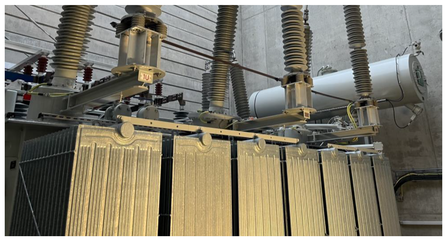
Figure 2.
Principal sketch of clamping system, windings, and sensor layout (blue circles).
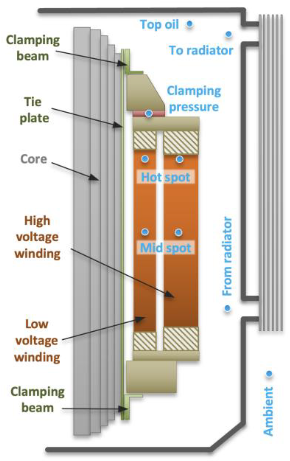
Figure 3.
Simplified single line diagram for 132/18 kV substation. The circuit breakers (CB) are operated to energise and load the transformers T1 and T3 individually.
Figure 3.
Simplified single line diagram for 132/18 kV substation. The circuit breakers (CB) are operated to energise and load the transformers T1 and T3 individually.
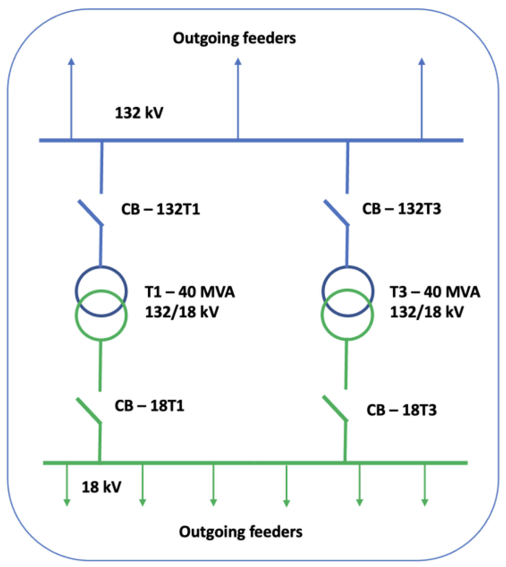
Figure 4.
Scheme of operations during the experiment. The arrows indicate the following operations: O1 – de-energise; O2 – energise and load; O3 – remove load and de-energise; O4 –energise; O5 – load; O6 – remove load and de-energise; O7 - energise and load; and O8 – remove load.
Figure 4.
Scheme of operations during the experiment. The arrows indicate the following operations: O1 – de-energise; O2 – energise and load; O3 – remove load and de-energise; O4 –energise; O5 – load; O6 – remove load and de-energise; O7 - energise and load; and O8 – remove load.
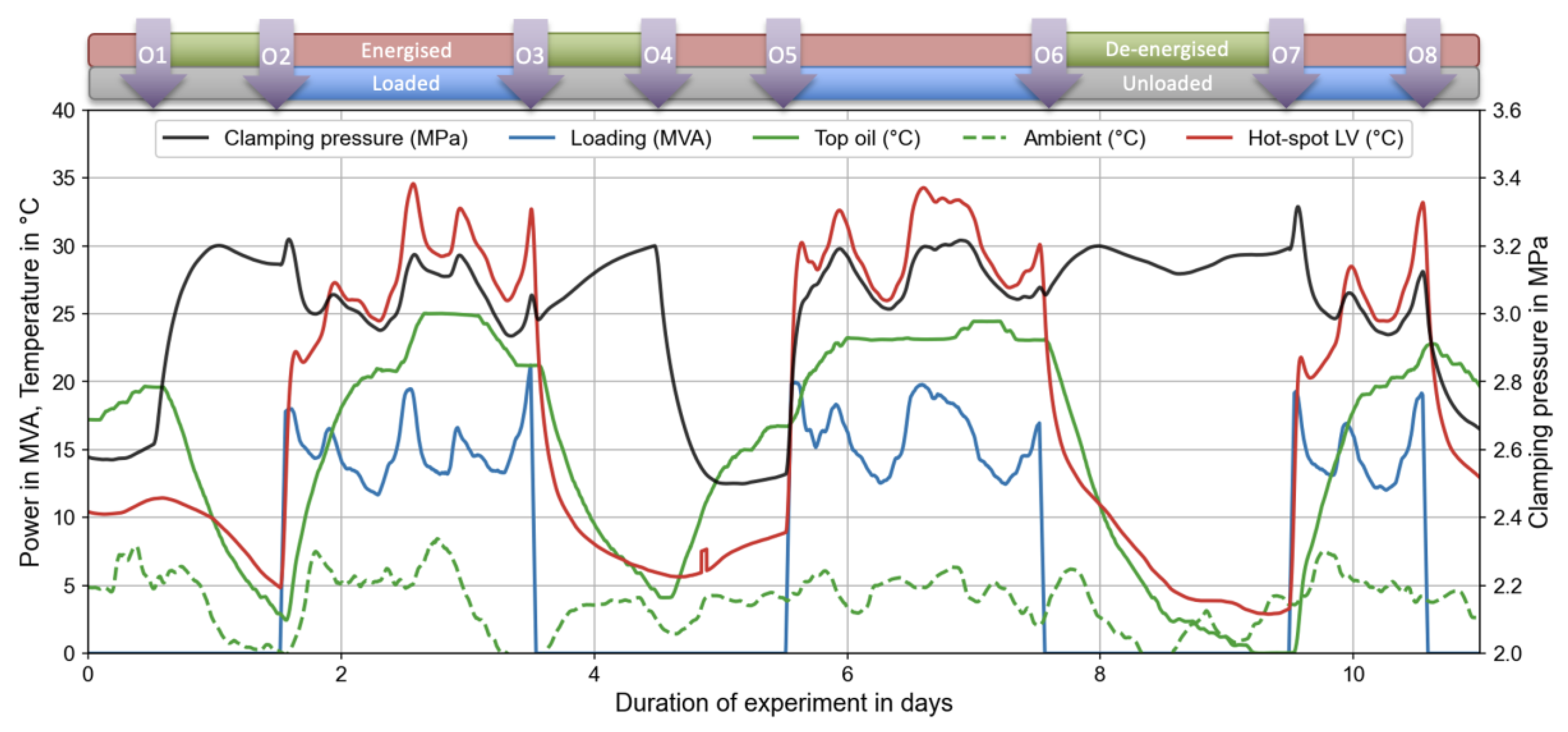
Figure 5.
Applying step load to the transformer, with (left, O5) and without (right, O7) prior energisation.
Figure 5.
Applying step load to the transformer, with (left, O5) and without (right, O7) prior energisation.
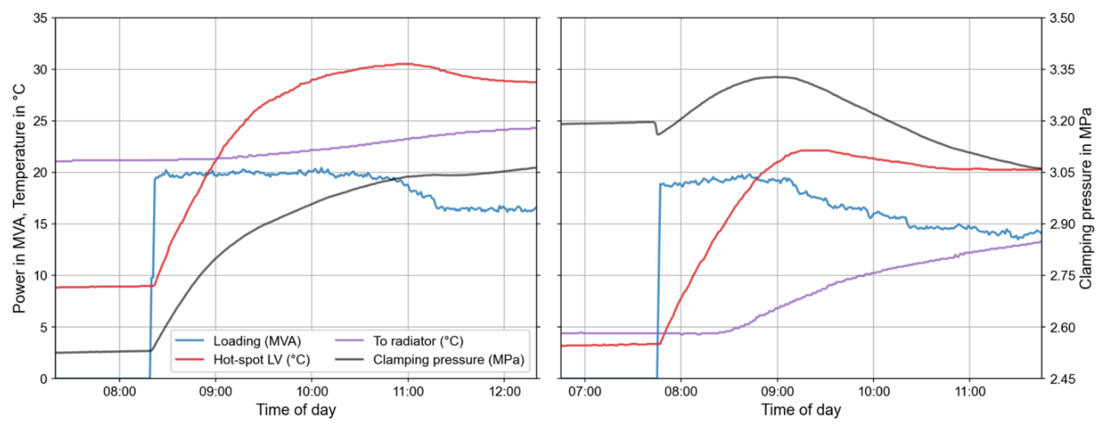
Figure 6.
De-energising (left, O1) and energising (right, O4) the transformer under no load. Note that the loading here is zero and hardly visible on the zero line of the figures, but it is kept in the legend to be consistent with the other similar figures.
Figure 6.
De-energising (left, O1) and energising (right, O4) the transformer under no load. Note that the loading here is zero and hardly visible on the zero line of the figures, but it is kept in the legend to be consistent with the other similar figures.
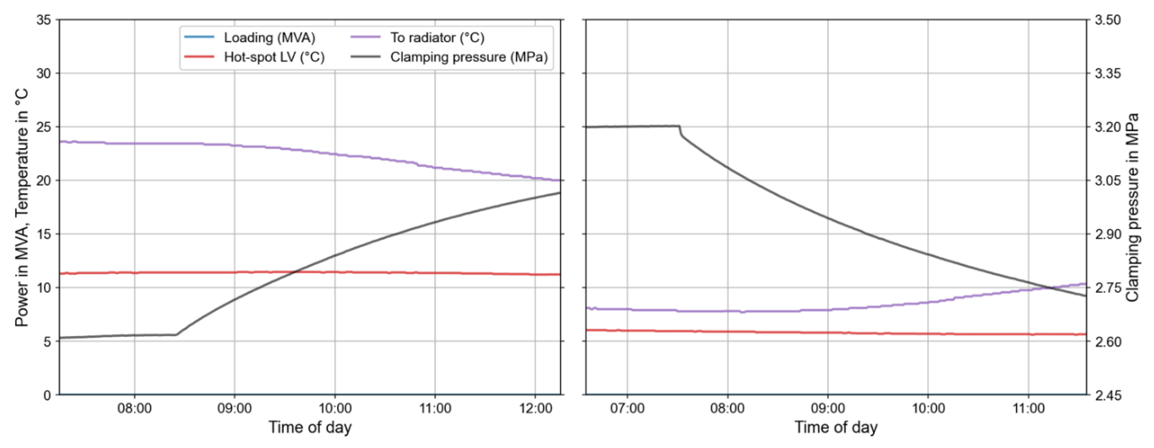
Figure 7.
Removing the load of the transformer, then keeping energisation (left, O8) and removing energisation (right, O6).
Figure 7.
Removing the load of the transformer, then keeping energisation (left, O8) and removing energisation (right, O6).
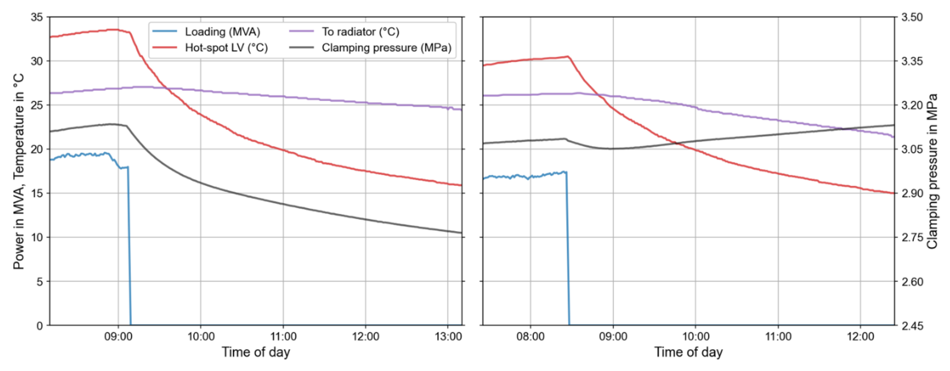
Figure 8.
Thermal response of the transformer when applying step load to about 20 MVA, with (left, O5) and without (right, O7) energisation.
Figure 8.
Thermal response of the transformer when applying step load to about 20 MVA, with (left, O5) and without (right, O7) energisation.
Disclaimer/Publisher’s Note: The statements, opinions and data contained in all publications are solely those of the individual author(s) and contributor(s) and not of MDPI and/or the editor(s). MDPI and/or the editor(s) disclaim responsibility for any injury to people or property resulting from any ideas, methods, instructions or products referred to in the content. |
© 2024 by the authors. Licensee MDPI, Basel, Switzerland. This article is an open access article distributed under the terms and conditions of the Creative Commons Attribution (CC BY) license (http://creativecommons.org/licenses/by/4.0/).
Copyright: This open access article is published under a Creative Commons CC BY 4.0 license, which permit the free download, distribution, and reuse, provided that the author and preprint are cited in any reuse.


