
Submitted:
09 April 2024
Posted:
10 April 2024
Read the latest preprint version here
Abstract
The thesis proposes a argument that a mass point moving in a horizontal circle on the Earth's surface can generate a radial centrifugal force of the Earth's center of mass, thus realizing an unconventional anti-gravity path. And through the theoretical analysis of the difference in the distribution of gravitational acceleration at different latitudes caused by the rotation of the earth, and the centrifugal force of a mass point moving in a horizontal circle on the earth's surface is analyzed, the validity of the argument is demonstrated. At the same time, the paper puts forward two possible basic principles, and makes theoretical analysis and demonstration. Conceive of the concrete experimental verification of principle two is proposed. Four technical schemes for antigravity ascent are proposed and basic analysis is made. On the premise of not fully considering the practical technical ability, it is theoretically proved that three of them have realistic operability and development potential. In theory, this paper opens up a different way of anti-gravity for human beings, which will bring new ideas and prospects for human beings to get rid of the bondage of gravity.
Keywords:
gravitation
; Centrifugal force
; Gravity
1. Introduction
Getting rid of the gravitational pull of the Earth or the sun is an important human aspiration.
In addition to some traditional antigravity pathways, are there other antigravity pathways? The answer is that there must be, but it is limited to the level of scientific understanding and technological development of mankind, and it has not been discovered or can not be done.
The author proposes that a mass point moving in a horizontal circle on the Earth's surface can generate a radial centrifugal force of the Earth's center of mass, thus realizing an unconventional anti-gravity path. The difference in the distribution of gravitational acceleration in different latitudes caused by the rotation of the earth is analyzed theoretically, and the conclusion is drawn that the mass point moving in a conical plane circular around the Earth's center of mass (The circumference of the motion is not in the same plane as the Earth's center of mass, and the apex of the cone is the Earth's center of mass, such as horizontal circular motion at the surface) can produce the radial centrifugal force of the Earth's center of mass, thus affecting the weight of the mass point. Through further theoretical analysis of mass points moving in a horizontal circle on the Earth's surface, it is obtained that the mass points moving in a conical plane circle around the Earth's center of mass and the mass points moving in a two-dimensional plane circle around the Earth's center of mass(The circumference of the motion is in the same plane as the Earth's center of mass, such as the orbit of the satellite moving in a circle around the Earth), with other parameters being the same, The radial centrifugal force of the Earth's center of mass produced by the two is equivalent. Of course, there is also a big difference between the two, the difference is that the mass point moving in a conical plane circular around the Earth's center of mass, in addition to producing the equivalent radial centrifugal force of the Earth's center of mass, will also produce a larger horizontal circular radial centrifugal force. Here, there are two different concepts, one is the radial centrifugal force at the center of a horizontal circle; The other is the radial centrifugal force of the Earth's center of mass.
This paper also proposes an experimental verification hypothesis. Although I do not have the ability to complete this experimental verification, but the technical difficulty of this experiment is not large, a little technical and financial strength of the unit or individual can be completed. Through this experiment, we can prove whether an important part of the thesis is true.
The thesis of this paper is mainly to explore a new anti-gravity way in theory, maybe there are still great difficulties in realizing it technically. However, if this idea is feasible through theoretical analysis and experiment, human beings can continue to make breakthroughs in technology to achieve it. To this end, the author also put forward four anti-gravity technology path implementation scheme, and the corresponding application feasibility analysis is carried out. On the premise of not fully considering the practical technical ability, from the theoretical point of view, it proves that three of the technical solutions have practical operability and development potential.
If the anti-gravity principle proposed by the author can be verified by the experiment, it is proved to be valid. Then, mankind will get a different way of anti-gravity, will open up new prospects for mankind to get rid of the bondage of gravity.
2. Theoretical analysis and demonstration
We know that the linear velocity of an Earth satellite moving uniformly in a circle around the Earth's low Earth orbit must be greater than or equal to the first cosmic velocity (i.e., 7.9km/s). When the satellite reaches the first cosmic velocity, even if there is no other driving force (and no atmospheric drag), the satellite will remain in a state of suspension and will not fall to the Earth's surface. There should be no objection to this conclusion, because it is an objective fact that has been proven. In this conclusion, the linear velocity is a key parameter. At the same time, this conclusion holds regardless of how the tangent direction of the velocity changes. For example, this conclusion (that the satellite will also remain suspended and will not fall to the Earth's surface) holds regardless of the Angle between the satellite's orbital plane and the Earth's equatorial plane. Of course, this velocity has a precondition problem of the reference frame, that is, the reference frame must be a spherical reference frame with the Earth's center of mass as the origin, and is absolutely stationary relative to the Earth's rotation. In order to avoid over-complicating the problem, increasing the difficulty of understanding. This paper basically avoids the problem of reference frame. For more serious readers interested in this frame of reference issue, please read references [1,2,3].
Now let us suppose that at the same height above the Earth's surface (outside the atmosphere) a mass point (or satellite) moves uniformly in a horizontal circle around the center of a circle with radius r (suppose r is 4, 6 meters, etc.). If its linear velocity also reaches the first cosmic velocity (avoid the question of how this can be done, although this is important and will be discussed later), would the mass point also remain suspended and not fall to the surface of the Earth?
My answer is that it will remain suspended and will not fall to the surface of the Earth. Because the velocity of this mass point is always a stationary reference frame with the Earth's center of mass as the origin and the tangent velocity of the same radius (there are some differences in the absolute tangent velocity caused by the earth's rotation, for the time being, do not consider it, so as not to cause confusion). The difference is that the direction of this tangential velocity also changes regularly. According to "This conclusion holds regardless of how the tangent direction of the velocity changes." The view of, like a satellite moving in a constant circle around the Earth, this mass point will remain suspended too. Of course, there are big differences between them. First, the geometry of the movement is different; In the same frame of reference with the Earth's center of mass as the origin, the geometric pattern of uniform circular motion around the earth (that is, the orbital plane does uniform circular motion around the earth's center of mass) is called: two-dimensional plane circular motion around the Earth's center of mass; The geometric pattern of uniform motion in a horizontal circle of the earth's surface around the center of a circle with radius r is called: circular motion in a conical plane around the center of mass of the Earth. Second, the force structure of the mass point (or satellite) is different; These questions will be discussed in detail later.
Generalize about: A mass point moving in a horizontal circular motion on the Earth's surface (a circular motion in a conical plane around the Earth's center of mass) can generate a radial centrifugal force on the Earth's center of mass, thus achieving an unconventional anti-gravity path.
Therefore, this paper makes a theoretical analysis and demonstration of this argument from three aspects.
2.1. Analysis of Gravitational Acceleration at Different Latitudes of the Earth
We already know that the acceleration of gravity is not the same everywhere on the Earth's surface. There are many factors affecting it, but from the analysis of the factors of the earth itself, there are two main reasons. First, the earth is not a standard normal circle, and the radius of the earth's center of mass (or center of gravity) at different points on the surface is not the same, resulting in a slight difference in the acceleration of gravity. Second, due to the rotation of the earth, the linear velocity of the fixed mass point on the surface of the earth at different latitudes is not the same, forming the difference in centrifugal force, resulting in some differences in the acceleration of gravity.
Due to the rotation of the Earth, there are two basic geometric modes of motion of fixed mass points on the Earth's surface. One is the two-dimensional planar circular motion geometry around the Earth's center of mass; Like mass points on the surface of the equator. The second is the geometric pattern of circular motion in a conical plane around the earth's center of mass; Other than the equator, all fixed mass points on the Earth's surface have this geometric pattern of motion. Both of these basic geometric motion patterns affect the acceleration of gravity, and the physical principles are the same. That is, because the linear velocity around the Earth's center of mass is different, the radial centrifugal force of the Earth's center of mass is different, resulting in different gravitational acceleration. That is to say, the physical principle of the influence of two different geometric motion modes on the acceleration of gravity is equivalent, that is, the physical principle of generating the radial centrifugal force of the earth's center of mass is equivalent.
The geometry of a mass point moving in a horizontal circle on the Earth's surface is exactly the same as the geometry of a fixed mass point moving on the Earth's surface at a certain latitude due to the Earth's rotation. That is, they all belong to the geometric pattern of circular motion in a conical plane around the Earth's center of mass. Therefore, the physical principle that produces the radial centrifugal force of the Earth's center of mass should also be equivalent.
Therefore, "due to the rotation of the earth, the linear velocity of the fixed mass point on the surface of the earth at different latitudes is not the same, forming the difference in the radial centrifugal force of the Earth's center of mass, resulting in some differences in the acceleration of gravity" this view is valid. This proves that "a mass point moving in a horizontal circle on the Earth's surface (circular motion in a conical plane around the Earth's center of mass) can generate a radial centrifugal force on the Earth's center of mass." The argument holds.
Based on Newtonian mechanics and related theories of geophysics [4], a simple analysis of the acceleration of gravity at different latitudes caused by the rotation of the earth is made to explore the basic principle of the difference in the acceleration of gravity.
Let a stationary mass point m on the ground at latitude φ of the Earth's centroid, Its radius from the Earth's axis of rotation is r, the radial centrifugal force vector at the center of a fixed mass point moving in a circle around the axis of rotation due to the rotation of the earth is Fr, the component of the radial centrifugal force vector of the Earth's centroid generated by the mass point m is F'R, and the radial gravitation force of the Earth's centroid subjected by the mass point m is FR, as shown in Figure 1.
Fr=ma
Among:
a=vm2/r
Therefore:
Fr=mvm2/r
F’R=Frcosφ
Because:
cosφ=r/R
Therefore:
where: vm is the linear velocity of the mass point (caused by the rotation of the Earth).
F’R=mvm2/R
vm=2πr/T=2πRcosφ/T
T is the time it takes the Earth to rotate once, taking 86,164 seconds. R is the distance of the mass point from the Earth's center of mass:
where: a is the equatorial radius of the Earth. f is the oblateness of the Earth, it is 3.3528679×10⁻³.
R≈a(1-fsin2φ)
Then the actual gravitational force Fφ and gravitational acceleration gφ of a mass point at the Earth's centroid latitude φ are:
Fφ=FR-F’R
FR=GMm/R2
Fφ=GMm/R2-mvm2/R=mgφ
gφ=GM/R2-vm2/R=GM/R2-4π2R(cosφ)2/T2
A mass point located on the equator of the earth's surface, φ=0; To the Earth's centroid radius R0=a=6378137 meters (Note: data from [4] page 68, Table 2.1); T=86164s; GM=3.986004418×10¹⁴(m3/s2).
g0=9.798285-0.033916=9.764369(m/s2)
Let the earth centroid latitude 450, φ=45 degrees,
R45≈a(1-fsin2φ)=6367444.5 meter
g45=9.831221-0.016929=9.814292(m/s2)
Let the geographical latitude be φ',
φ’=φ+fsin(2φ)=45.0033530
Located at the Earth latitude 900 (rotation pole), φ=90 degrees, R90=6356752 meters.
g90=9.864322(m/s2)
Under the above ideal condition, the theoretical calculation results are highly consistent with the actual values, and the reason for a little error should be the deviation of the actual distance from the mass point to the earth's centroid and the influence of other factors(e.g. the gravitational influence of the sun, moon, etc.). Taking away the difference in radius from the Earth's center of mass, The earth's rotation causes the maximum linear velocity on the equator, and the radial centrifugal force formed by the Earth's center of mass is also the largest, so the gravitational acceleration on the equatorial surface is the smallest; The Earth's rotation does not create linear velocity on the surface of the poles (spin axis poles), nor does it generate radial centrifugal force at the Earth's center of mass, so its gravitational acceleration is maximum. Prove that formula (07) is correct, and therefore formula (03) must also be correct. From formula (03), it can be concluded that: A mass point moving in a conical plane around the earth's center of mass (the apex of the cone is the center of the Earth's center of mass) can produce radial centrifugal force, which affects the weight of the mass point. At the same time, it was proved that "a mass point moving in a horizontal circle on the Earth's surface (moving in a conical plane circle around the Earth's center of mass) can generate a radial centrifugal force on the Earth's center of mass." This argument is also valid.
2.2. Centrifugal Force Analysis of Mass Points in Horizontal Circular Motion on the Earth Surface
According to the above conclusions, it is inferred that a mass point moving in a horizontal circular motion on the Earth's surface is also a conical horizontal circular motion around the Earth's center of mass, and the geometry of its motion is exactly the same as that of a fixed mass point on the surface formed by the earth's rotation under the same frame of reference. Therefore, this mass point will also produce the radial centrifugal force of the Earth's center of mass, and the physical principle of producing the radial centrifugal force of the Earth's center of mass is the same. As shown in Figure 2:
Therefore, formula (03) is also suitable for calculating the magnitude of the radial centrifugal force of the Earth's center of mass for a mass point moving horizontally in a circle on the Earth's surface.
According to formula (03) F’R=mvm2/R, the magnitude of the radial centrifugal force of the earth's centroid of a mass point moving in a horizontal circle on the Earth's surface is determined by three parameters: the mass m of the mass point, the linear velocity vm of the mass point (expressed as v on the line of FIG. 2) and the distance R of the mass point from the Earth's centroid. And there is no direct relationship with the radius r of the circumference of the horizontal circular motion. Formula (01) and formula (03) are exactly the same except that the radius (distance) parameters are different. It is also proved that the different radial centrifugal force vectors generated by the circular motion of different geometric types are equivalent in physical principle. It's just that the parameters of the radial radius distance are different.
Set up an efficiency parameter, that is, the ratio of the radial centrifugal force F’R of the Earth's centroid generated by the mass point to the weight of the mass point, referred to as the gravity ratio ρ :
g is the gravitational acceleration.
ρ=F’R/mg=v2/gR=v2R/GM
It is obvious that only when ρ≥1, the mass point that produces the radial centrifugal force of the earth's center of mass may be suspended or soar because the centrifugal force is greater than or equal to the gravitational force (mass point weight), so as to achieve the purpose of anti-gravity.
Set ρ≥1, from (08) can be obtained:
V0≥(gR)1/2 =(GM/R)1/2
V0 is the critical velocity for suspension.
Take the earth as an example, R takes the radius of the earth 6.378×10⁶ meters, and calculates according to the formula (09), obtaining:
V0≥(3.986×10¹⁴/6.378×106)1/2≥7905.45m/s
The results are basically consistent with the first cosmic velocity, It shows that, theoretically speaking, the radial centrifugal force generated by the conical plane circular motion of a mass point around the Earth's center of mass and the two-dimensional plane circular motion around the earth's center of mass are exactly equivalent when other parameters are the same.
2.3. Analysis of Two Possible Basic Principles
According to the above analysis, there may be two basic principles for the radial centrifugal force generated by the conical plane circular motion of a mass point around the Earth's center of mass:
Principle 1: The radial centrifugal force F’R of the Earth's center of mass of a mass point is a component of the radial centrifugal force Fr of the center of its horizontal circle; That is, F’R is determined by Fr, and F’R is not an independently generated centrifugal force.
Principle 2: The radial centrifugal force F’R of the Earth's center of mass of a mass point and the radial centrifugal force Fr of its horizontal circle are two relatively independent centrifugal forces. There are three reasons for this:
First, the essence of centrifugal force is that the linear velocity of a mass point is always perpendicular to the radial direction of the earth's center of mass or the radial direction of the horizontal circle. When a mass point moves in a conical plane circle around the Earth's center of mass, the linear velocity of the mass point is always perpendicular to the Earth's center of mass and also perpendicular to the center of the horizontal circle. Therefore, two independent radial centrifugal forces should also be generated separately.
Second, according to formula (03), the radial centrifugal force F’R of the Earth's centroid of a mass point has no direct relationship with relevant parameters of the horizontal circumference (such as the radius r of the horizontal circumference). It is only directly related to the mass of the mass point, the linear velocity of the mass point and the distance of the mass point from the Earth's center of mass. Therefore, the radial centrifugal force F’R of the Earth's center of mass of a mass point should be independently generated.
Thirdly, according to the analysis in 2.2, the radial centrifugal force generated by the conical plane circular motion of a mass point around the Earth's center of mass is equivalent to that generated by the two-dimensional plane circular motion around the Earth's center of mass when other parameters are the same. Therefore, the conical plane circular motion of a mass point around the Earth's center of mass can be regarded as the same as the two-dimensional plane circular motion around the Earth's center of mass, and the radial centrifugal force of the Earth's center of mass can be independently generated.
Either principle one or principle two must be true. Although the formula for calculating the radial centrifugal force of the particle center of the Earth in Principle 1 and Principle 2 is the same, the physical meaning generated by the two principles is different.
Under normal circumstances, principle one is relatively easy to understand and easy to be accepted by everyone. Principle two is more difficult to understand and requires a proper experiment to verify.
3. Experiment to Verify the Hypothesis of Principle 2
Whether principle 2 is true or not has extremely far-reaching theoretical value and physical significance for the in-depth research and development of macro and micro physics (this issue is not the subject of this paper, and will not be further discussed in this paper). Therefore, it is necessary to carry out experimental verification.
3.1. Basic Assumptions of the Experiment
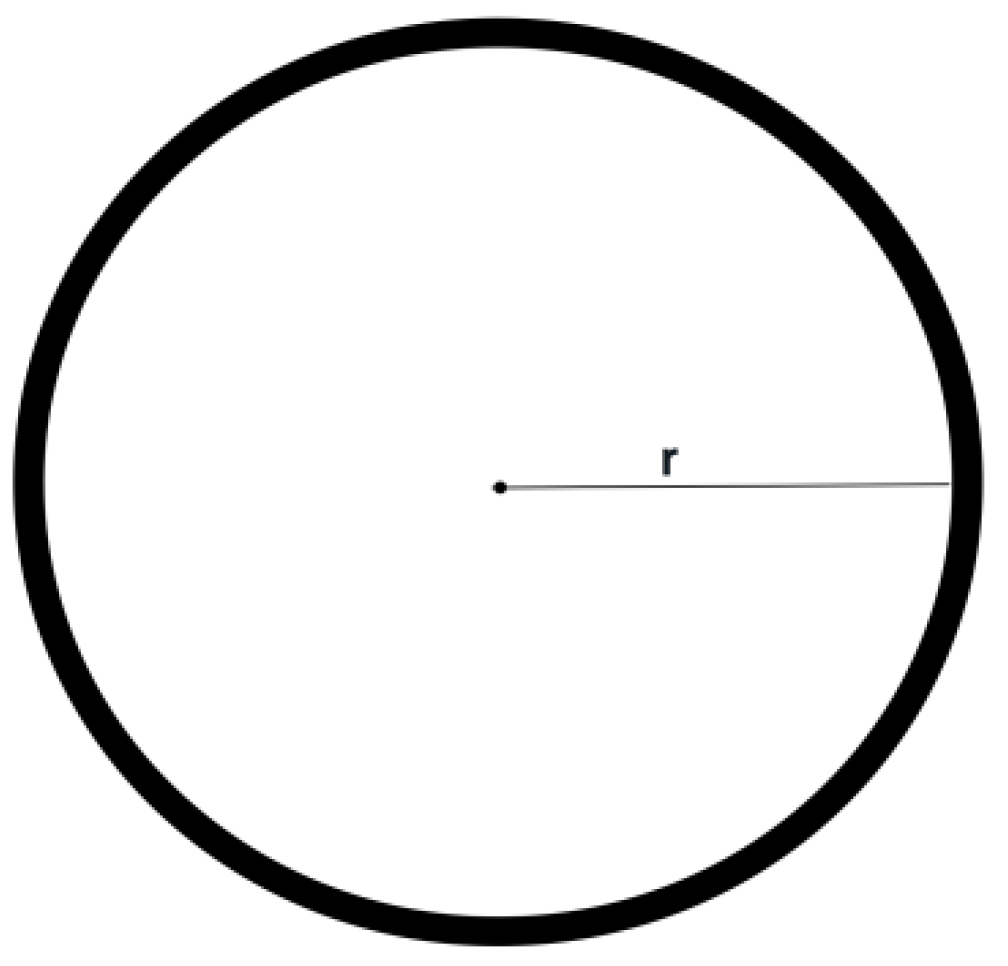
Make a rigid body ring with an inner radius of r and a stationary weight of m (as shown in Figure 3). If a rigid body ring moves in a horizontal circle around its center, each particle on the rigid body ring must generate centrifugal force in the radial direction of the circle center. However, due to the binding of the rigid body, the radial centrifugal force of the center of the ring will form the internal stress between the molecules inside the rigid body, but will not form the external centrifugal force. Therefore, if principle 2 is not true, because the radial centrifugal force outside the rigid body ring does not exist, then the rigid body ring does not produce the radial centrifugal force component of the Earth's center of mass. If the second principle is true, then the radial centrifugal force of the earth's center of mass is generated by the ring stiffness, which reduces the weight of the rigid body ring.
3.2. Composition of Experimental Device
The experimental facility consists of two sets of systems (devices), a high-speed rotating circular rigid body system device and a weight measurement system device.
The high-speed rotating circular ring rigid body system device comprises a rigid body ring, a connecting rod and a shaft sleeve connected with a rotating shaft; Power drive system; Independent power supply system; Horizontal Angle adjustment device of rigid ring; Rotary speed recording, display and adjustment device for rigid ring.
The weight measuring system device is a suitable electronic scale. The main requirements are appropriate weighing range and weighing accuracy.
3.3. Basic Requirements
To ensure the accuracy of the experiment and the reliability of the data, reduce various interference factors. In addition to some of the device requirements mentioned above, there must be some basic requirements for the experimental device:
One is to try to avoid the experimental error caused by mechanical vibration. Therefore, the high-speed rotating circular rigid body system device should have higher machining accuracy and vibration reduction measures.
Second, try to avoid the error caused by air disturbance to the experiment. Therefore, the high-speed rotating circular rigid body system can not produce lift or fall force brought by air; And try to take internal and external air isolation measures to avoid errors caused by air disturbance.
3.4. Parameter Setting and Calculation of the Experiment
The rest weight of the rigid ring is considered 10-40 kg, With a radius of 0.5 to 1 meter; The speed should consider that the particle line speed on the rigid ring is lower than the sound speed to avoid unnecessary influence on the experiment.
Assuming that the rest weight of a rigid ring is m0=20kg, radius r=0.5 m, GM=3.986004418×10¹⁴(m3/s2 ), the linear velocity of the particle is 0.9 times the sound speed v=306 meters, then the rotation speed of the ring rigid body n=v/2πr=97.4 RPM/s, take the integer n=100 RPM/s.
where: R is the distance between the rigid ring and the Earth's center of mass, taking 6378 km.
Δm=-F’R/g=-m0v2/gR=-4m0(πrn)2/gR=-4m0R(πrn)2/GM
Δm=-0.03145kg=-31.45g
The above calculation does not take into account the error caused by other factors such as mechanical vibration and air disturbance, as well as the error caused by the radial thickness of the rigid ring and the omission of the connecting rod and the sleeve. According to the technical and economic conditions of the experimenter, the above parameters can also be adjusted and calculated accordingly.
According to the above parameter experiments, if the total weight of the high-speed rotating circular rigid body system is reduced by about 30 grams than its static state, principle 2 must be established. If the total weight of the high-speed rotating circular rigid body system is reduced by very little compared to its rest state, within the possible margin of error, then principle 2 is not true.
4. Anti-Gravity Technology Realization Path Assumption
This paper mainly constructs the realization path of anti-gravity technology in theory, and does not discuss the practical technology and capability. At present, it is not possible to confirm which of the two basic principles is correct, so the realization path of anti-gravity is synthesized according to the two principles.
In addition, an antigravity system is composed of a variety of devices, the total weight of the system must exceed the weight of the horizontal circular motion of the object providing the antigravity. For this purpose, a gravity ratio parameter ρz considering the total weight M of the antigravity system is set up.
ρz=mv2/gMR
v≥(gMR/m)1/2
At the same time, set up an anti-gravity lift-to-weight ratio parameter (similar to the thrust-to-weight ratio of aircraft engines) Q:
Q≤M/m=(v/v0)2
4.1. Technical Path of Horizontal Circular Motion of a Rigid Body Particle
According to formula (09), when a rigid body particle does horizontal circular motion, its linear velocity must reach 7905.45 m/s or more, in order to have actual anti-gravity value. Its critical speed is 23.3 times the speed of sound. In the range of the Earth's atmosphere, there may be too much drag and high temperature to achieve. Therefore, it is necessary to consider the horizontal circular motion of a rigid particle in a vacuum environment.
There are two options.
Scheme 1: In the vacuum of the circular pipe, according to the electromagnetic gun and magnetic levitation principle (can also consider the application of superconducting technology), by the number of n independent rigid body particles, in accordance with the equidistant queuing way to do horizontal circular high-speed movement.
The advantage of scheme 1 is that it can be applied regardless of whether Principle 1 or principle 2 is true.
Technical difficulties:
First, how much is the speed limit of rigid particle; According to reports, the speed of the electromagnetic gun can reach 11 km/s, and the potential speed is about 100 km/s. In a vacuum environment, and a rigid particle can be accelerated for a long time, its potential velocity should be very large.
The second problem is the control of the motion trajectory of a rigid particle. That is, the rigid particle must be in a magnetic levitation state in all directions, and can not collide and friction with the tube wall and the rigid particle.
Third, in the case of ultra-high speed, the rigid body particle will inevitably produce a great centrifugal force in the radial center of the circular motion, and what is the limit of this centrifugal force borne by the system.
Assume that the weight of each rigid body particle is 6 kg, the circle radius of the vacuum circular ring pipe is 2 meters, the distance between the rigid body particle is 6 cm, the total number is about 200, the total weight is 1200 kg; The maximum linear speed is 50 km/s. Then:
Q=(v/v0)2=(50/7.92)2=39.85
M≤1.2×39.85=47.8 tonne
Its physical meaning is that under the conditions of the above parameters, it can theoretically drive the anti-gravity system with a total weight of less than 47.8 tonnes to achieve suspension and flight. Therefore, without considering the technical realization ability, scheme I has operability and development potential.
In addition, in order to control the rotation of the anti-gravity system in suspension state as a whole, the device for horizontal high-speed circular motion of rigid body particles should be configured with two sets of devices with opposite rotation directions. That is, one set of devices does clockwise horizontal rotation, and the other set does counterclockwise horizontal rotation. Alternatively, the rotation of the anti-gravity system can be controlled by other means.
Scheme 2: In the vacuum circular pipe, according to the principle of electromagnetic gun and magnetic levitation (can also consider the application of superconducting technology), a rigid body ring is placed and the horizontal high-speed rotation movement is done.
The advantages of scheme 2 are: first, the ability to resist the radial centrifugal force of circular motion is greatly improved; A rigid ring and an electromagnetic device can be combined to resist the radial centrifugal force of the center of the circle in circular motion. Secondly, it is much easier to control the motion path of rigid ring than scheme 1. The disadvantage is that scheme 2 only applies to the premise that principle 2 is established, if principle 2 is not established, scheme 2 cannot be established. Other technical parameters are the same as scheme 1. Scheme 2 also has operability and development potential under the premise that Principle 2 is established.
4.2. Path of Charged Particle Ring Accelerator
Scheme 3: In a horizontal ring particle accelerator [5], due to the high speed of particles that can be obtained in the accelerator, according to the above principle analysis, high-speed particles should not only generate radial centrifugal force at the center of the ring, but also radial centrifugal force at the center of the Earth's mass, so as to achieve the purpose of anti-gravity.
At present, particle speeds close to the speed of light can be obtained in particle accelerators. In order to obtain the best performance, the ratio of the total weight of the device to the total mass of the high-speed particles in the accelerator must be resolved in the best performance state.
It is assumed that the maximum speed of particle acceleration is limited to 0.4C, and the optimal beam density of particles in the accelerator is n particles/unit volume, the total resting mass of particles in the accelerator is nm0U, m0 is the rest mass of a single particle, and U is the total volume of the vacuum pipe of the ring accelerator. Then:
v=0.4C=1.2×10⁸ (m/s)
v/v0=15151.5
Q=M/m=2.3×108
m=nm0U/(1-v2/c2)1/2
Therefore, the beam density n is one of the most important parameters.
From the basic data of the above analysis, it is assumed that scheme 3 has a very high development potential without taking into account other physical and technical factors.
Of course, there will be many other technical problems, but what is to be considered in the envisioning phase is the theoretical possibility of the path being realized. Therefore, whether it can be done technically can not be considered for the time being.
4.3. Path of a Circular Superconductor Coil (or a Combination Thereof)
Scheme 4: A circular superconductor coil (or a combination thereof) in the horizontal state inputs a large amount of current. Because the electrons have mass, and the drift speed in the superconducting toroidal coil is relatively high. Therefore, according to the above principle analysis, in addition to the radial centrifugal force of the ring, the radial centrifugal force of the earth should also be generated, so as to achieve the purpose of anti-gravity.
According to informal data, electrons drift through superconductors at a speed of about 52 meters per second, v/v0 is only about 6.5×10⁻³, ρ=8.3×10⁻⁷. It is obvious that this proposed path does not achieve anti-gravity operability in reality from the current theoretical and technical point of view.
5. Conclusions and Recommendations
- 5.1
- Starting with the theoretical analysis of the difference in the distribution of gravitational acceleration caused by the earth's rotation, this paper draws the conclusion that a mass point making a conical plane circular motion around the Earth's center of mass (the conical apex is the Earth's center of mass) can produce radial centrifugal force of the Earth's center of mass, thus affecting the weight of the mass point.
- 5.2
- Through further theoretical analysis of mass points moving horizontally in circular motion on the Earth's surface, it is concluded that the radial centrifugal force generated by conical plane circular motion around the Earth's center of mass and two-dimensional plane circular motion around the earth's center of mass are equivalent when other parameters are the same.
- 5.3
- Through comprehensive analysis, it is proposed that there may be two basic principles for the radial centrifugal force of the Earth's center of mass generated by the conical plane circular motion of a mass point around the earth's center of mass, and one of the two principles must be valid. The possibility of principle 2 is analyzed, and the theory proves that principle 2 should be established.
- 5.4
- For principle 2, the hypothesis of experimental verification is proposed. The method and basis for judging whether the principle 2 is true are put forward.
- 5.5
- According to the theoretical basis of this paper, four anti-gravity technology paths are proposed. And the corresponding application feasibility analysis is carried out. On the premise of not fully considering the practical technical ability, from the theoretical point of view, there are three schemes with operability and development potential.
Due to the preliminary discussion and assumption, the breadth and depth of theoretical analysis are far from enough, and the discussion, analysis and assumption are only broad lines, and many problems are not taken into account. I hope that aspiring colleagues can put forward more criticism and suggestions, and jointly in-depth research and development.
In addition, the second principle proposed in this paper is very valuable for in-depth research and development of physics. It provides a new research direction for the study of the repulsive force of macroscopic universe and microscopic particles. It is hoped that capable units or individuals can complete the experimental verification of principle 2 in this paper.
References
- Zhao, S.; Zhao, Y. On the Hafele-Keating Experiment and the Geostationary Orbit Satellite Problem Further Analysis and Discussion. Preprints 2024, 2024021554. [CrossRef]
- S. Zhao, "Discussion on Physical Space Issues," 2023 Photonics & Electromagnetics Research Symposium (PIERS), Prague, Czech Republic, 2023, pp. 183-185. [CrossRef]
- Zhao, S.; Luo, J. An Analysis of the Basic Principles of Relativity and the Elaboration and Demonstration of Different Space-Time Concepts. Preprints 2024, 2024020347. [CrossRef]
- William Lowrie. Geophysical Equations (In Chinese) [M]. Translated by Zhang Liyun et al. Beijing: China Machine Press,2022.
- GUI Wei-Xie. Principle of Charged Particle Accelerator (In Chinese) [M]. Beijing: Tsinghua University Press,1994.
Figure 1.
Schematic diagram of the stress structure of fixed surface mass points at different latitudes caused by the rotation of the Earth.
Figure 1.
Schematic diagram of the stress structure of fixed surface mass points at different latitudes caused by the rotation of the Earth.
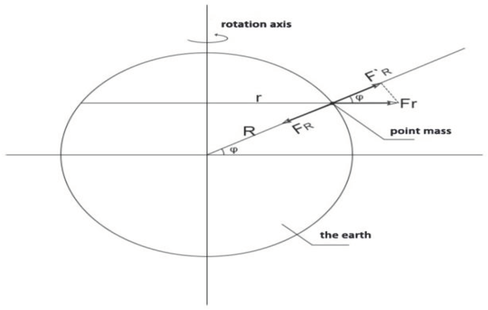
Figure 2.
Schematic diagram of the force structure of mass points in horizontal circular motion on the earth surface.
Figure 2.
Schematic diagram of the force structure of mass points in horizontal circular motion on the earth surface.
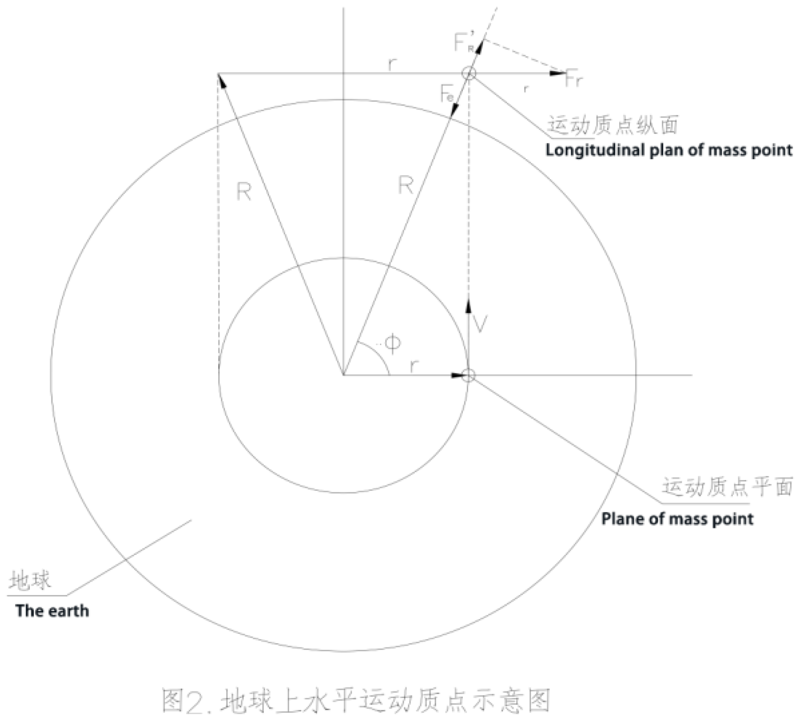
Figure 3.
Schematic diagram of a rigid ring.
Disclaimer/Publisher’s Note: The statements, opinions and data contained in all publications are solely those of the individual author(s) and contributor(s) and not of MDPI and/or the editor(s). MDPI and/or the editor(s) disclaim responsibility for any injury to people or property resulting from any ideas, methods, instructions or products referred to in the content. |
© 2024 by the authors. Licensee MDPI, Basel, Switzerland. This article is an open access article distributed under the terms and conditions of the Creative Commons Attribution (CC BY) license (http://creativecommons.org/licenses/by/4.0/).
Copyright: This open access article is published under a Creative Commons CC BY 4.0 license, which permit the free download, distribution, and reuse, provided that the author and preprint are cited in any reuse.


