
Submitted:
14 March 2024
Posted:
15 March 2024
You are already at the latest version
Abstract
The design complexity of the new generation of civil aero-engines results in higher demands on engines’ components, higher component temperature, higher heat generation, and, finally, critical thermal management issues. This paper will propose a methodological approach to create physics-based models for heat loads developed by sources as well as a systematic sensitivity analysis to identify the effects of design parameters on the thermal behaviour of civil aero-engines. The ranges and levels of heat loads generated by heat sources (e.g., accessory gearbox, bearing, pumps, etc.) and heat absorption capacity of heat sinks (e.g., engine fuel, oil, and air) are discussed systematically. The practical research challenges for thermal management system design and development for the new and next generation of turbofan engines will then be addressed through a sensitivity analysis of the heat load values as well as the heat sinks flow rates. The potential solutions for thermal performance enhancements of propulsion systems will be proposed and discussed accordingly.
Keywords:
Thermal Management System
; Heat Loads
; Aero Engines
1. Introduction
Thermal Management Systems (TMS) play an essential role in aircraft engines performance enhancement by dealing with the excess heat loads generated in heat sources components (e.g., bearings, gearboxes, pumps, generators, etc.) at different flight phases. The main objective of the TMS is to transfer these excess heat values to aircraft heat sinks (e.g., fuel, oil, air) and use this source of energy to enhance the performance of the propulsion system and the aircraft accordingly. Another objective of the TMS is to control the surface temperature of the propulsion system components to protect them against over-temperature that affects the performance of the components especially Power Gearbox (PGB) in geared turbofan engines, Accessory Gearbox (AGB), and electrical components in More Electric Aircraft (MEA). Respect to the very tight regulations set in the net zero 2050 strategy and Flight Path 2050 as well as increasing values of heat loads in new generation of aircraft engines, the optimal design of thermal management system is vital to enhance the performance of the propulsion system and to reduce the emission level of aircraft accordingly. A typical architecture of a TMS for the state-of-the-art propulsion system is shown in Figure 1. As sketched in this figure, the TMS works in two levels: the propulsion system level and the airframe level. In the propulsion level, the engine oil loop and fuel loop should be designed and integrated in an optimal way. At the airframe level, the avionics and environmental control system thermal management should also be taken into account. The lubrication oil is normally used as the coolant in the components to absorb the generated heat. The hot oil will then go through heat exchangers (e.g., Fuel Oil Heat Exchanger (FOHE) and Air Oil Heat Exchanger (AOHE)) to transfer the absorbed heat to either engine fuel or air. The fuel with a higher temperature will enhance the performance of the engine and the cooled oil will be back in the tank to close the TMS loop. If the fuel has not had enough capacity to take all the absorbed heat (due to certification limitations or operating temperature limits), the engine bypass and/or ram air could be used as another heat sink. The amount of oil flow rate, the order of lubricating the components, and the architecture of the thermal management system will strongly depend on the heat load values and available heat sinks at different flight phases.
As a summary, the TMS should cope with three main challenges including component surface temperature, the temperature of the working fluid, and increasing thermal load values in new and next generation propulsion systems [2]. The consequences of these issues will negatively affect the aircraft’s fuel consumption and emissions level due to its sensitivity to weight, ram and/or external aerodynamic drag caused by installing cooling systems [3]. Figure 2 lists some key examples showing how the selection of suitable heat sinks has varied over time. The larger the size of the air vehicle, the more variety of heat sinks is required for dealing with the thermal loads generated in the aircraft.
A more comprehensive literature review shows that more than 1400 documents were published from 1964 that were completely or partially related to aircraft TMS study. It is clear that the research interest in TMS is increasing dramatically due to the increasing power demand and visibly the thermal loads of aero engines (Figure 3).
In general, based on Pal and Severson [5], the TMS procedure includes 5 steps as shown in Figure 4, which are heat loads developed in heat sources, heat acquisitions, thermal transport, heat rejection, and heat absorption in the terminal heat sink. Heat sources can be systems or components that generate excess heat either as a by-product of their function (such as energy-inefficient systems) or as their primary function (like cabin heaters) that need to be managed [3]. Heat acquisition will take place in the heat source components to transfer the excess heat to the coolant (e.g., oil). As the use of local cooling may only sometimes be feasible in some cases, and waste heat must be transported over longer distances to heat sinks, so this is where thermal transport mechanisms are required. The heat rejection mechanisms work in a similar manner to heat acquisition mechanisms or on the reverse principle. Finally, the terminal heat sinks refer to the destination of the thermal energy (e.g., fuel, air). In aircraft, fuel is an important heat sink since there is usually a large supply available which can be transported from one part of the aircraft to another. Preheating fuel before inserting it into the combustion chamber also has a thermodynamic advantage in enhancing the thermal efficiency of the engine; however, the use of fuel as a heat sink is not without risks and limitations, such as its flammability and tendency to coke when heated above certain temperatures.
Therefore, it is important to have an accurate vision of the value and levels of heat loads generated by heat sources to develop the propulsion system heat map. This heat map will then be used as the input in the design procedure of the thermal management system based on Figure 4 philosophy. This paper will present and classify heat load values generated by heat sources at different classes of turbofan engines. A preliminary sensitivity analysis will also be carried out to illustrate the trend of technology in TMS design for new and next generation propulsion systems.
2. Methodology and Approach
In this section, the methodology and approach employed will be outlined. Initially, an overview of the heat sinks and heat sources in a standard civil-aero engine will be provided. Following this, the modeling process used to calculate power losses in various components will be presented.
2.1. Aero Engines Heat Sources and Sinks
As mentioned above, the thermal management system in gas turbine aero engines is to get the thermal loads produced in engine heat sources, use coolant to transfer the loads to heat sinks and distribute the thermal loads to engine heat sinks based on their capacity at different flight phases. So, depends on the number of heat sources, the value of the thermal loads generated at different flight phases, the type and characteristics of the coolant, the size and capacity of the heat sink, the architecture of the thermal management system and the cooling mechanism used in that would be defined. The typical heat sources, sinks, and coolants used in aero engines are listed in Table 1.
The procedure of design and simulation of an aero-engine thermal management system could be started with physics-based modelling of engine heat sources in which a mathematical thermal model for engine bearings, gearboxes, pumps, etc., will be developed to calculate the values of the thermal loads generated in each source in various operating conditions. There is an in-house developed software at Cranfield University for this purpose [6,7,8], and a brief description of the models, how they can be developed and validated, and the related pseudo codes and equations are provided in the below section.
2.2. Modelling Procedure
The accessory gearbox (AGB) drives the accessories of the engine like the generator, fuel and oil pumps, hydraulic pumps, etc. Accordingly, it is an essential element for the operation of the engine or the aircraft on which it is mounted. The power loss mechanisms inside the gearbox can be separated into two groups: non-load dependent losses and load-dependent losses. Non-load dependent losses include churning losses caused by gears, seals, and bearings, and load-dependent losses are frictional losses caused by gears and bearings [9]. The power gearbox (PGB) is a reduction gearbox between the fan and the low-pressure (LP) shaft allowing the latter to run at a higher rotational speed thus enabling fewer stages to be used in both the LP turbine and the LP compressor, increasing efficiency, and reducing weight. In PGB, the load-dependent loss is the sum of the bearing friction loss and the gear mesh loss. There are mechanical losses associated with friction between mating gear teeth, which generate these losses. There are three types of load-independent losses: bearing churning losses, gear windage losses, and oil seal losses. In comparison with other heat-producing mechanisms, the latter is usually ignored since its contribution is very small. Fluid-dynamic effects, bearing viscous losses, and trapped fluid between gear teeth all contribute to these losses [6]. In summary, the total power loss can be the sum of non-load dependent and load-dependent losses.
Furthermore, the heat loads generated in bearings are friction losses caused by several types of movements, such as sliding and rolling, and drag between the lubricant can not and rolling elements [10]. Sliding friction losses are mainly happened at low speeds due to micro slip of one surface over another one in rolling motions. Rolling friction losses are due to deformation effects and elastic hysteresis. Other heat loss mechanisms including drag friction and seal friction are normally generated when lubricant acts as friction force against the direction rolling elements and by the heat generated between the contact surfaces between the seal rubber and shaft respectively. SKF proposed a formula for bearing loss [11]. Figure 5, Figure 6 and Figure 7 show the methodology to calculate heat losses in AGB, PGB, and bearings.
3. Results
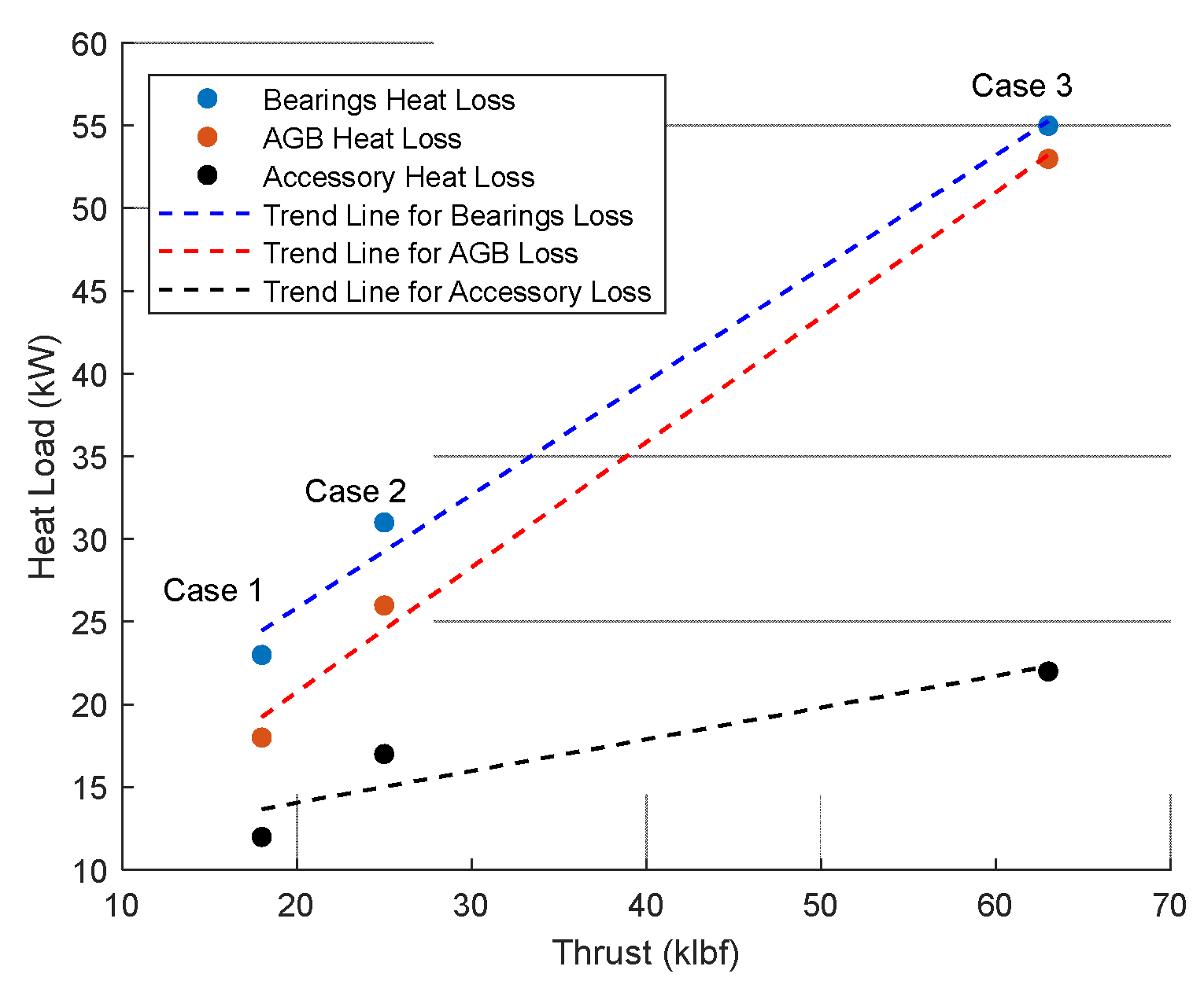
The result of these research works show that the size of the engine (maximum thrust) has the biggest effect on the thermal load values, which is the main parameter in the thermal management system design procedure. In order to discuss this effect, typical values of the heat loads at take-off conditions. generated in different sizes of civil turbofan engines are listed in Table 2. Three case studies have been selected for this purpose:
- The first case is a CFM-56 size engine with a take-off thrust of 18 klbf (80 kN). The simulation results obtained by Cranfield in-house developed toolbox shows that 53 kW of heat load should be transferred to the engine oil at take-off condition, including 18 kW from the accessory gearbox, 23 kW from the engine shaft bearings, and another 12 kW from the engine pumps, seals, etc. The validity of the results is verified through the MTU paper [12].
- The second case study shows that by increasing the size of the engine from a conventional turbofan engine to a geared one, a PW1100G size engine with a take-off thrust of 112 kN (25 klbf), the total heat to oil will be increased dramatically. The results of the physics-based model developed for the TMS system of this engine show that the power gearbox is the main source of generated heat loads in geared turbofan engines. Although the efficiency of planetary gearboxes used in this type of engine is normally very high (above 97%), the heat load generated in this component is still very high due to the huge value of the transferred power by this component [6].
- For the third case study, one of the versions of the UltraFan engine (an Ultra High Bypass Turbofan with a take-off thrust of 280kN) has been simulated. The results show that even with the state-of-the-art technology in the PGB with the efficiency of above 99%, 592 kW of heat load will be generated in this component during the take-off (the engine low-pressure shaft power is around 64 MW [13]). The heat load values in bearings and accessory gearbox have also been increased proportional to the thrust of the engine.
3.1. Sensitivity Analysis of Heat Sources
An interesting result has been obtained from analysing of the heat loads at different case studies through a preliminary sensitivity check as illustrated in Figure 5. The thrust (in klbf) and the heat loads produced by bearings, AGBs, and accessories (in kW) seem to be linearly related and correlated. however, it can be seen that the effect of AGB in heat loss generation increases with thrust. This can be taken into account for future high-power demand engine design procedures. Moreover, despite the fact that results derived from the physics-based models for accessories did not show a very sensitive relationship with thrust, it is possible to explain this by taking into account that, in most cases, the amount of load for accessories does not change significantly. Although more real data and case studies are needed to strengthen the conclusions, some quick remarks can be listed as follows:
- In low thrust values, the amount of the thrust (in klbf) is correlated well with the value of AGB heat load (case studies 1 and 2).
- By increasing the thrust value, the correlation is more obvious with the bearing heat loads rather than those of the AGB.
- The slope of the bearing heat load values is higher than those of AGB and accessories. In other words, the thermal management system architecture design procedure is more sensitive to bearings characteristics than to AGB characteristics. This should be taken into account in the TMS design and development procedure as well as in the definition of degradation management strategies.
- As a rule of thumb, a linear relationship could be fitted to the values of heat loads generated in bearings and accessory gearbox as a function of thrust value. A more accurate curve-fitting procedure could be done by adding more case studies and experimental data to the
Figure 8.
Heat loads of different components vs engine thrust.
Another important aspect of the TMS that need to be discussed is the variation of PGB mechanical efficiency across the flight mission. For PGBs, it is true that their efficiency is typically high (more than 95% in modern engines); nevertheless, the amount of heat loss is still considerably high due to the huge amount of power that needs to be transferred by this component. Figure 9 shows PGB heat loss at different flight phases for the 3rd case study. The heat load generated in the PGB is a function of many parameters including low-pressure shaft power, rotational speed, geometry, oil characteristics, and material. The most important parameters in this regard are the shaft power and the rotational speed. So, the maximum heat load is being generated at take-off and the beginning of the climb.
Figure 10 shows the variation of mechanical efficiency in the PGB at different flight phases (numbers represent each phase as per Figure 6 legend). It should be noted that the efficiency is being changed at each flight phase (results are coming from the physics-based model presented in [6]) but except for the idle condition, this value is always above 97%. So, another rule of thumb says that the value of the heat load generated by the PGB in geared turbofans could be constrained as follows:
3.2. Sensitivity Analysis of Heat Sinks
After discussing the heat sources and their values, an initial study is conducted to determine the effects of oil mass flow on PGB, AGB, and bearings exit oil temperature. Two scenarios have been defined and simulated in this regard:
- Scenario I: Increase/decrease the oil mass flowrate in all components (changing the size of the oil pump and the oil tanks accordingly).
- Scenario II: changing the distribution of the oil flowrate in the components (in this scenario the size of the oil pump and other TMS components is fixed but the characteristics of the 3-way valve that distributes the oil flowrate to bearing, AGB, and PGB compartment will be changed).
Figure 11 shows the result of scenario I. It can be seen that decreasing the oil mass flow rate will affect the surface temperature (and therefore the performance) of all components. However, the PGB is the most sensitive component to the oil flow rate decrease. In other words, the results illustrate the importance of a precise health monitoring system for PGB lubrication in geared turbofan engines. Although the increase of the oil flowrate will positively decrease the temperature of the compartment, but it should be noted that this increase will result in a bigger oil tank and a heavier thermal management system that either may not be feasible from the design and manufacturing point of view or affect the performance of the whole propulsion system due to adding new weight to it.
Further, Figure 12 presents the results of the scenario II in which in one set of results 90% of the oil flowrate will go through the PGB, 5% to the AGB, and 5% to the bearings. In another set of results, 75% of the oil will be circulated in the PGB, and 15% for bearings and AGB will be used. The results show that the temperatures at the AGB exit oil were more affected by distribution differences than those of other exit oil temperatures. In other words, the design of bearings and PGB are approaching the optimum architecture in which the change of the oil flow rate will not have a huge effect on the oil exit temperature. According to [14], for the engine components, there is an optimum design point where oil mass flow should not significantly affect the exit temperature of the heat sources. Consequently, the optimal design of AGB for turbofan engines could be a very challenging topic for future research studies.
the broadest context possible. Future research directions may also be highlighted.
4. Conclusions
This paper presented a methodological approach in analysing the heat sources and heat sinks behaviour in thermal management of propulsion systems. Three civil engines with different values of thrust (including a high-bypass turbofan, a geared turbofan, and an ultra-high bypass turbofan) have been selected as case studies to discuss the heat load values in engine bearings, accessory gearbox, and power gearbox. The sensitivity of the heat load values to the engine thrust is also discussed to illustrate how these parameters are correlated. Moreover, a preliminary sensitivity analysis on the effects of coolant flow rate on engine components’ temperature is presented. The results of this study show the importance of having an accurate thermal management monitoring system in the next generation of propulsion systems, especially for power gearbox in geared turbofan engines, as well as the optimal thermal design of accessory gearbox to reduce its sensitivity to the coolant flowrate.
Author Contributions
Conceptualization, S.J. and A.E.; methodology, A.E. and S.J.; software, S.J., A.E., and T.N.; validation, A.E. and S.J.; formal analysis, A.E., and S.J.; investigation, A.E.; resources, S.J.; writing—original draft preparation, A.E.; writing—review and editing, A.E., S.J., T.N.; supervision, S.J., and T.N.; project administration, S.J, and T.N. All authors have read and agreed to the published version of the manuscript.
Funding
This research received no external funding.
Conflicts of Interest
The authors declare no conflict of interest.
Nomenclature
| Symbol | Unit | Meaning |
| Ai | m2 | Immersion surface area |
| b | m | Tooth face width |
| d | mm | Bearing bore diameter |
| D | m | Diameter of the rotating element |
| D1 | inch | Bearing bore diameter |
| D2 | inch | Outside diameter |
| DI | m | Planet bearing bore diameter |
| di | m | Shaft diameter |
| dm | mm | Pitch circle diameter |
| f | - | Friction coefficient |
| f0 | - | Bearing coefficient of loss |
| FA | N | Axial load |
| fe | - | External mesh coefficient of friction |
| Fr | - | Froude number |
| FR | N | Radial load |
| h | m | Immersion depth |
| Hν | - | Gear loss factor |
| M | N.mm | Friction moment |
| M0 | Nm | No-load torque planet bearing |
| Me | - | External mesh mechanical advantage |
| n | rpm | Shaft rotational speed |
| nB | rpm | Planet bearing rotational speed |
| P | N | Load of the bearing |
| PBL | kW | Bearing power loss |
| Pin | kW | Power input |
| PLB | kW | Power loss in bearings (AGB) |
| PLB0 | kW | Bearing churning loss (AGB) |
| PLG | kW | Power loss in meshing gear (AGB)s |
| PLG0 | kW | Gear churning power loss (AGB) |
| PMLE | kW | Friction power loss at sun/planet mesh |
| PMLI | kW | Friction power loss at planet/ring mesh |
| PSeal | kW | Seals churning loss |
| Pw | kW | Power loss due to windage |
| Q | kW | Thermal load |
| Re | - | Reynolds number |
| t | m | Disk thickness |
| TBL | Nm | Torque loss per bearing |
| TP | Nm | Planet gear torque |
| Voil | m3 | Oil volume |
| W | lb | Equivalent total load |
| βe | degree | Sun/planet angle |
| ϑ | mm2/s | Operating viscosity |
| μ | - | Friction coefficient |
| μ | Pa s | Lubricant dynamic viscosity |
| μm | - | Mean friction coefficient |
| ν | m2/s | Lubricant kinematic viscosity |
| ρ | kg/m3 | Lubricant density |
| ω | inch | Bearing width |
| Ω | rad/s | Rotational speed |
References
- Werner J. A. Dahm. Thermal Management in Aerospace Systems. 2008.
- Srinath AN, López ÁP, Fashandi SAM, Lechat S, Di Legge G, Nabavi SA, Nikolaidis T, Jafari S. Thermal Management System Architecture for Hydrogen-Powered Propulsion Technologies: Practices, Thematic Clusters, System Architectures, Future Challenges, and Opportunities. Energies 2022, Vol 15, Page 304. 2022 Jan 3 [cited 2022 Oct 12];15(1):304. Available from: https://www.mdpi.com/1996-1073/15/1/304/htm.
- van Heerden ASJ, Judt DM, Jafari S, Lawson CP, Nikolaidis T, Bosak D. Aircraft thermal management: Practices, technology, system architectures, future challenges, and opportunities. Progress in Aerospace Sciences. 2022 Jan 1;128:100767.
- Donovan AB, Bracey M, Roberts R, Wolff M, Yerkes K. American Institute of Aeronautics and Astronautics Cleared for public release: Distribution A case number Enhanced ECS/Generator Models in an Integrated Air Vehicle Platform. 2016 [cited 2022 Oct 12]; Available from: http://arc.aiaa.org.
- Pal D, Severson M. Liquid cooled system for aircraft power electronics cooling. undefined. 2017 Jul 25;800–5.
- Jafari S, Nikolaidis T, Van Heerden ASJ, Lawson CP, Bosak D. Physics-Based Thermal Model for Power Gearboxes in Geared Turbofan Engines [Internet]. 2020. Available from: http://asmedigitalcollection.asme.org/GT/proceedings-pdf/GT2020/84058/V001T01A021/6614031/v001t01a021-gt2020-14637.pdf.
- Jafari S, Nikolaidis T, Sureddi R. Physics-Based Thermal Management System Components Design for All-Electric Propulsion Systems. Proceedings of the ASME Turbo Expo. 2021;Volume 5B.
- Jafari S, Bouchareb A, Nikolaidis T. Thermal Performance Evaluation in Gas Turbine Aero Engines Accessory Gearbox. International Journal of Turbomachinery, Propulsion and Power. 2020;5(3). Available from: https://www.mdpi.com/2504-186X/5/3/21.
- Martins RC, Cardoso NFR, Bock H, Igartua A, Seabra JHO. Power loss performance of high pressure nitrided steel gears. Tribol Int. 2009 Dec 1;42(11–12):1807–15.
- Tu, M. Validation and modeling of power losses of NJ 406 cylindrical roller bearings.
- SKF Group Company. Friction and Temperature Rise. [cited 2023 Mar 29]. Available from: www.ntnglobal.com/en/products/catalog/pdf/2202E_a10.pdf.
- Streifinger H. Fuel/Oil System Thermal Management in Aircraft Turbine Engines, Symposium, Design principles and methods for aircraft gas turbine engines. In: RTO MEETING PROCEEDINGS- NORTH ATLANTIC TREATY ORGANIZATION RESEARCH AND TECHNOLOGY ORGANIZATION RTO MP, Design principles and methods for aircraft gas turbine engines, Symposium, Design principles and methods for aircraft gas turbine engines. NATO; ; 1999. p. 12. Available from: https://www.tib.eu/de/suchen/id/BLCP%3ACN029454648.
- Press releases | Rolls-Royce - Rolls-Royce UltraFan power gearbox tops world aerospace record [Internet]. [cited 2023 Mar 28]. Available from: https://www.rolls-royce.com/media/press-releases/2021/31-08-2021-rr-ultrafan-power-gearbox-tops-world-aerospace-record.aspx.
- Changenet C, Ville F, Velex P. Thermal Behavior of a High-Speed Gear Unit. [cited 2022 Oct 19]; Available from: www.geartechnology.com].
Figure 1.
Conventional TMS architecture for aircraft application (adapted from [1]).
Figure 1.
Conventional TMS architecture for aircraft application (adapted from [1]).
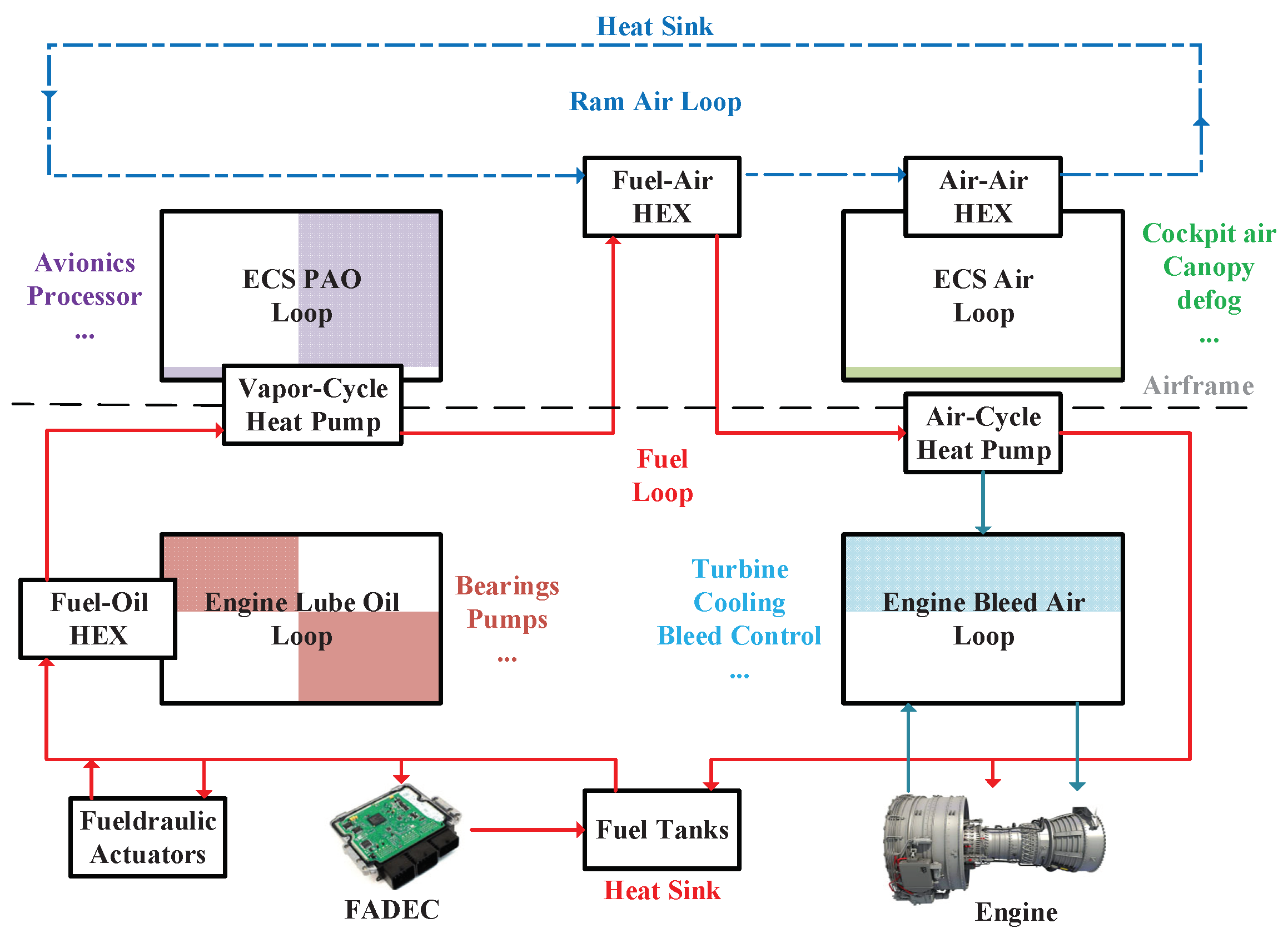
Figure 2.
Thermal loads over time (adapted from [4]).
Figure 2.
Thermal loads over time (adapted from [4]).
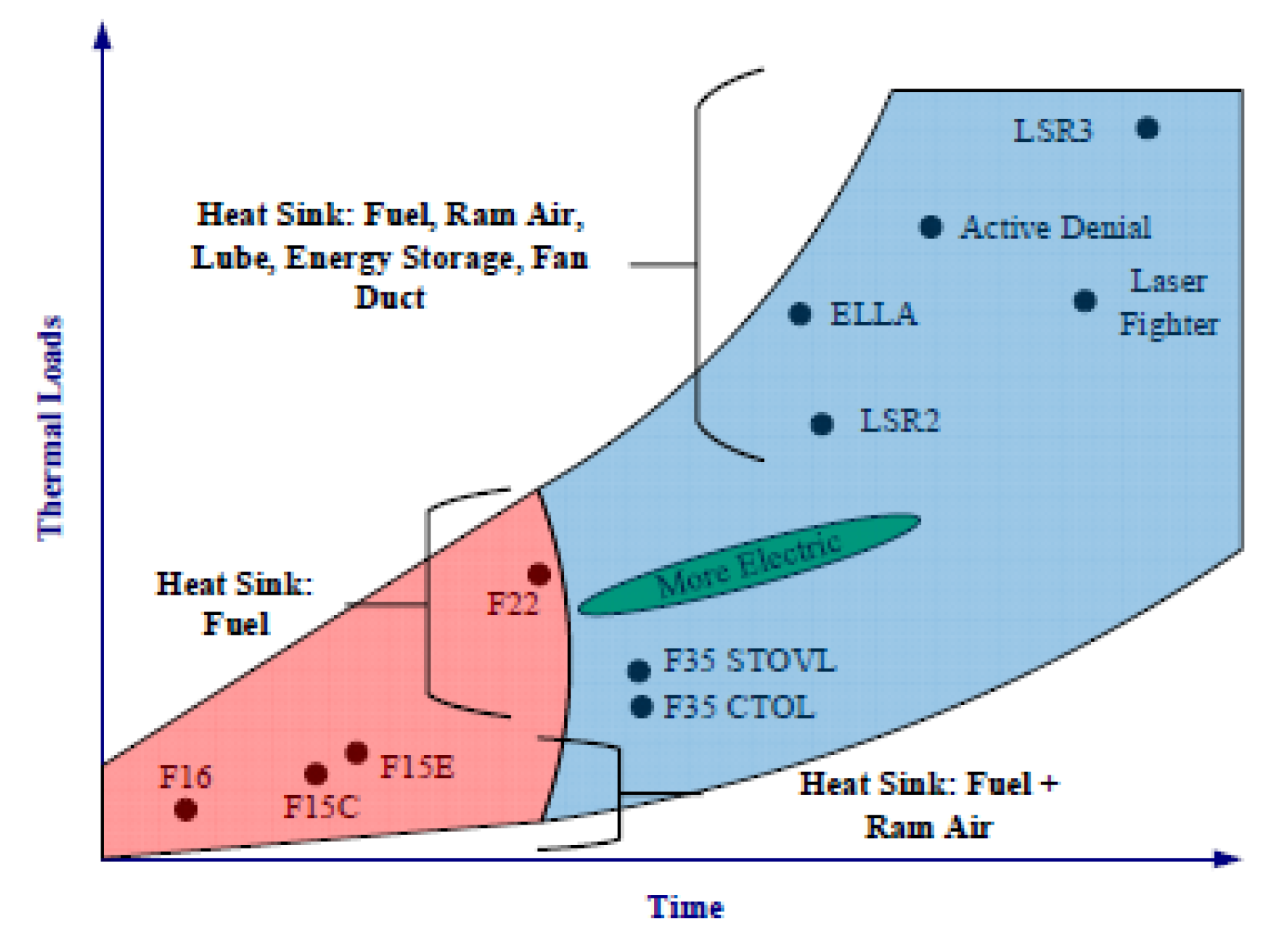
Figure 3.
Publication distribution over time about aircraft TMS.
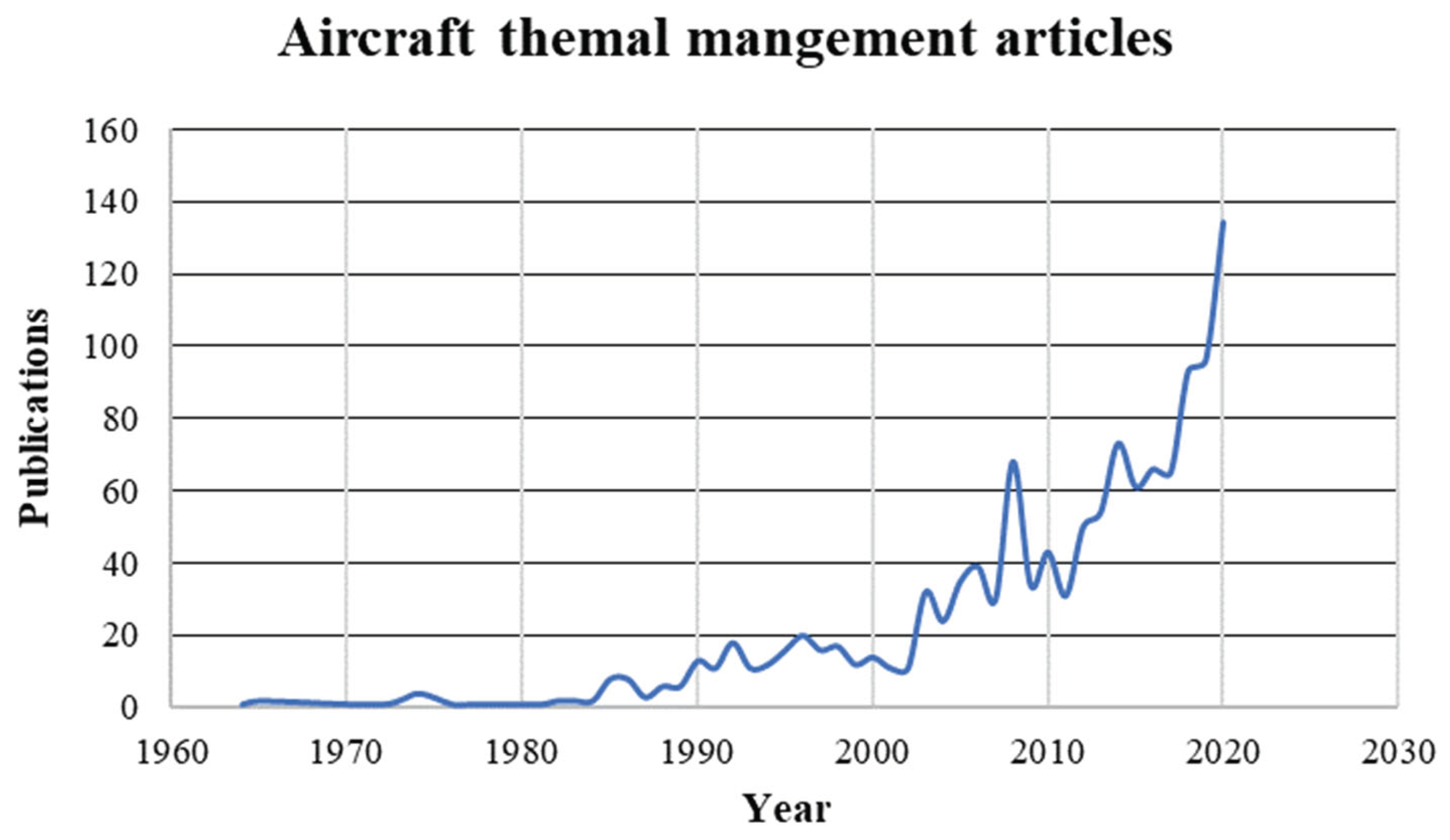
Figure 4.
Thermal Management Procedure.
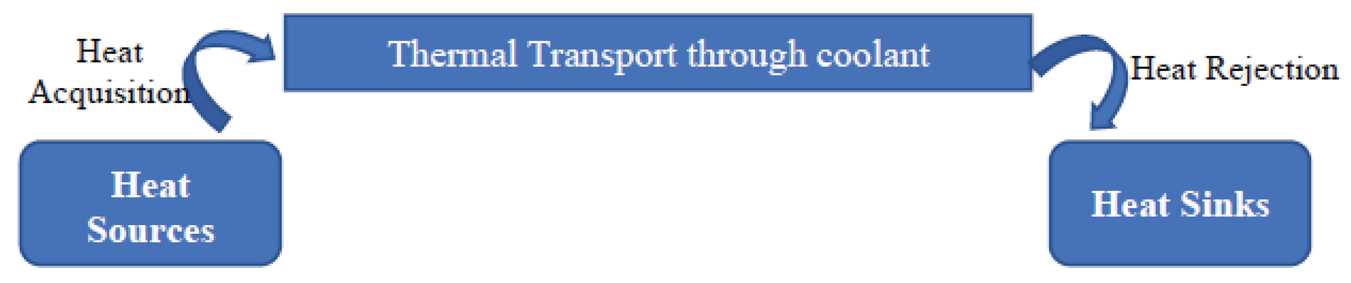
Figure 5.
AGB heat loss calculation.
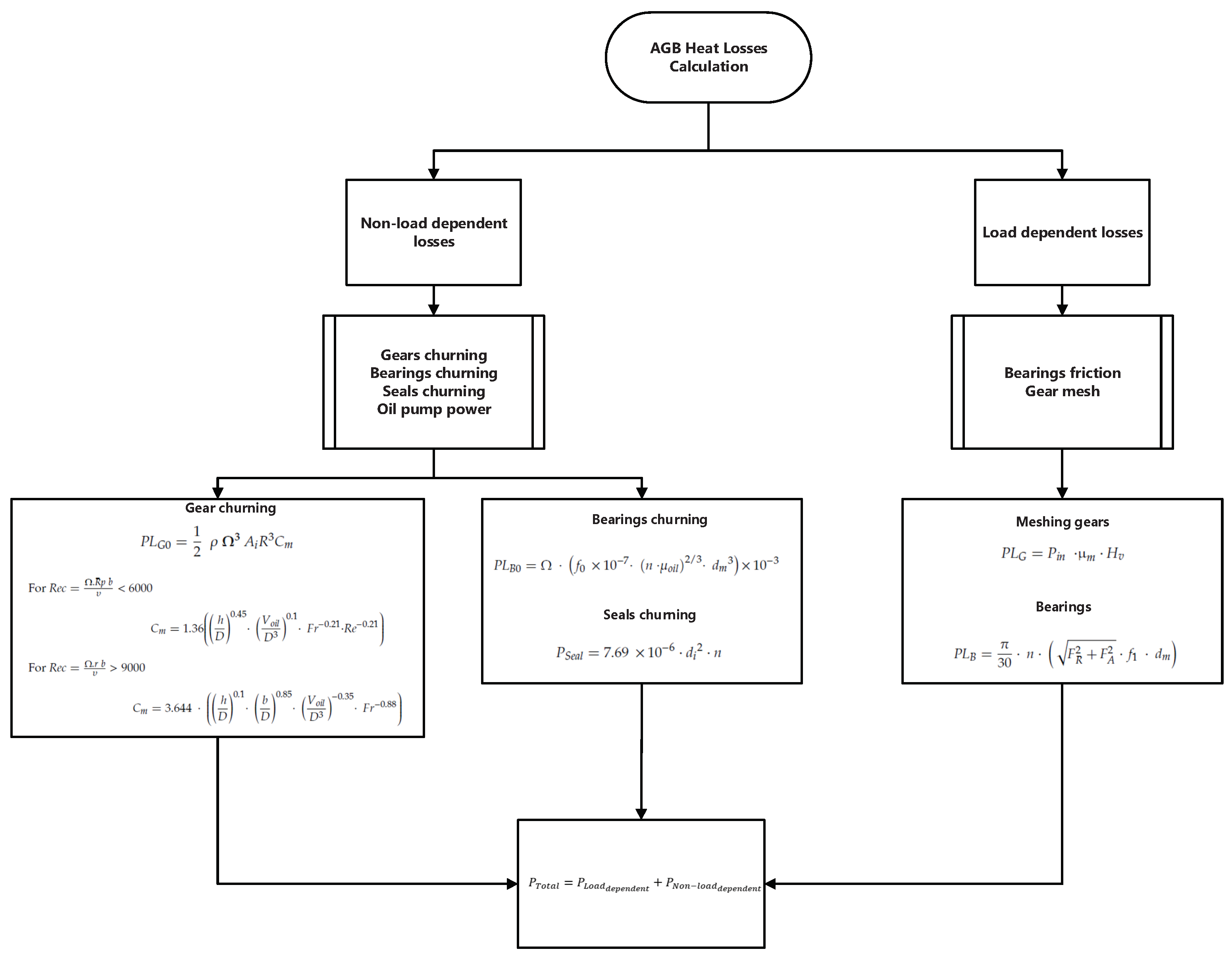
Figure 6.
Bearing heat loss calculation
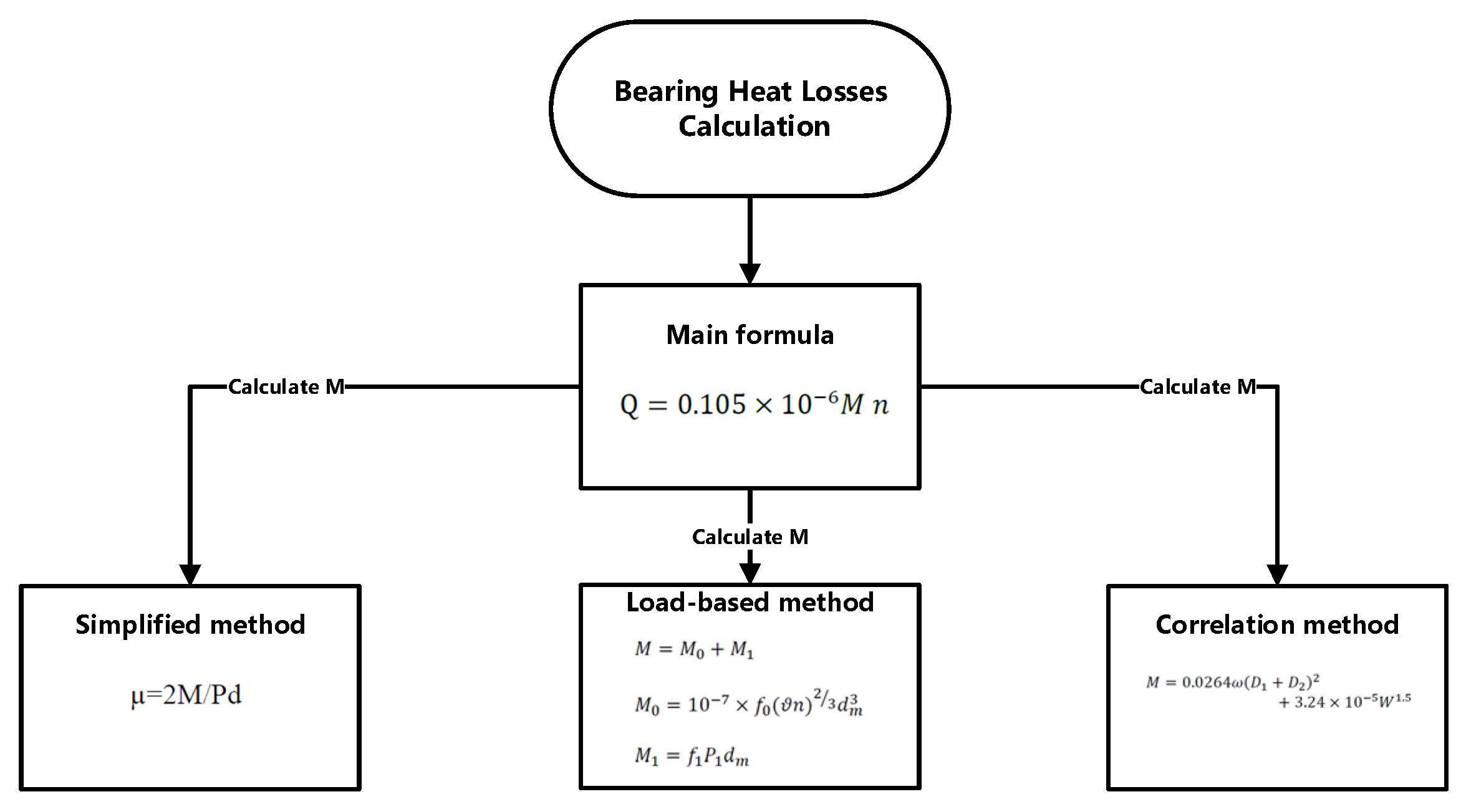
Figure 7.
PGB heat loss calculation
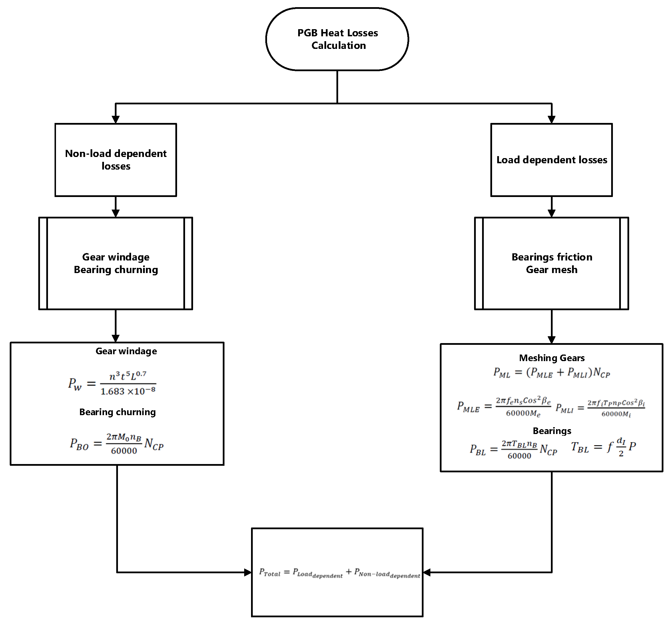
Figure 9.
PGB heat loss during flight.
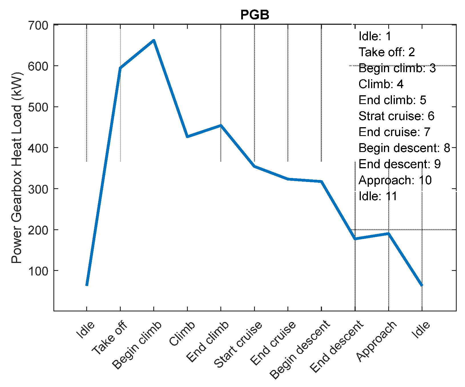
Figure 10.
PGB mechanical efficiencies during flight.
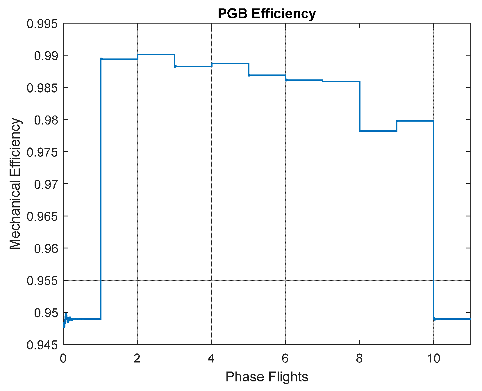
Figure 11.
Effect of oil mass flow rate on exit temperature (Scenario I).
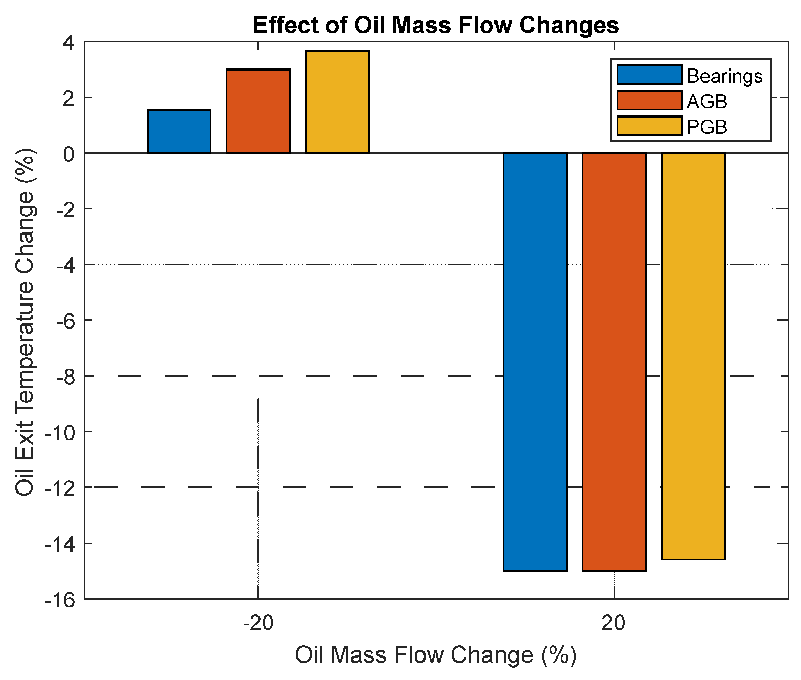
Figure 12.
Effect of oil mass flow distribution on exit temperature (Scenario II).
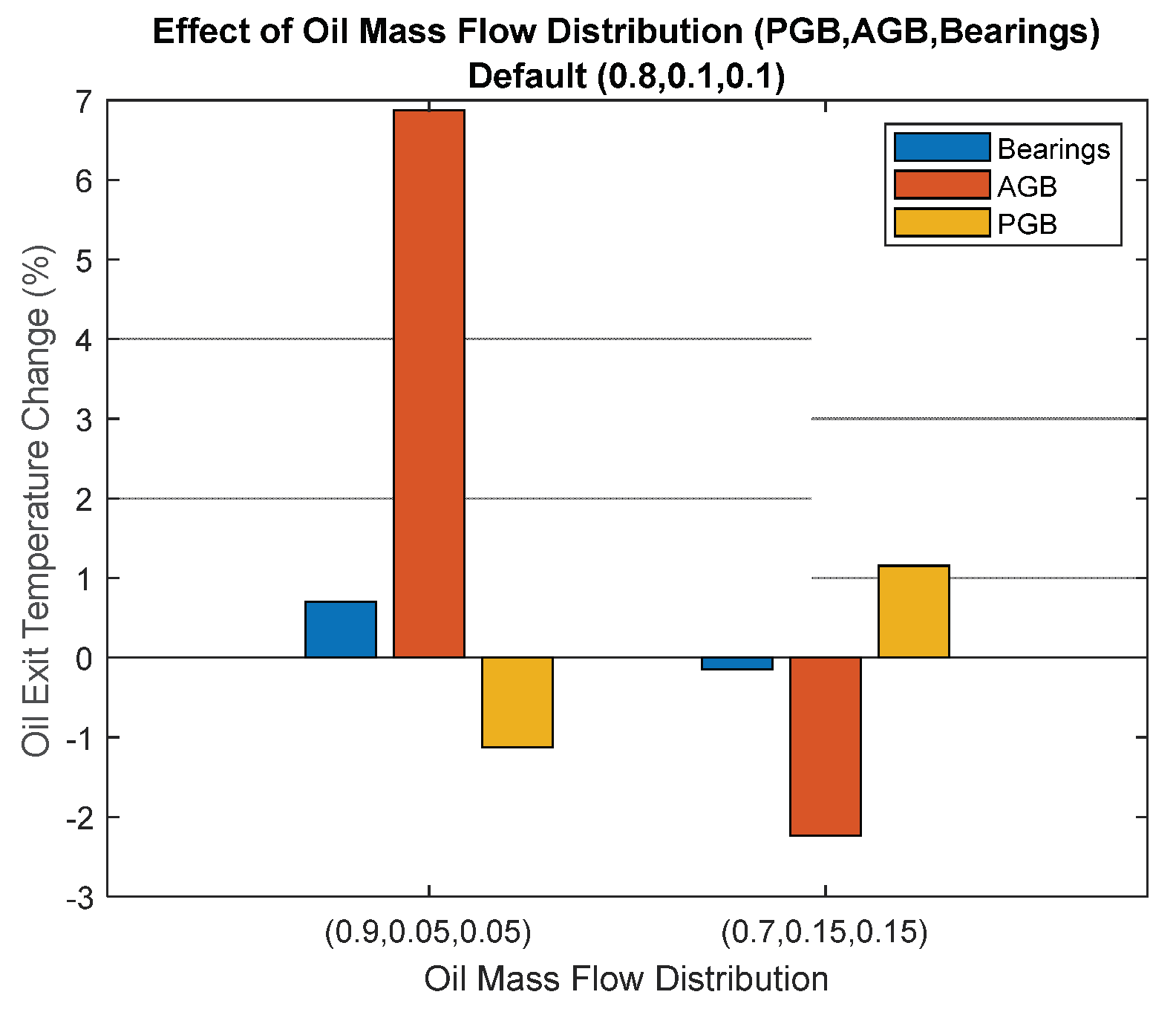

Table 1.
Heat sources, heat sinks and coolants used in aero engines.
| Heat Sources | Coolant | Heat Sinks |
|
|
|
Table 2.
Heat loads generated at take-off condition in different size of turbofan engines.
| Case study | Take-off thrust (klbf) | Bearings heat load (kW) | AGB (kW) | PGB (kW) | Pumps, seals, etc. (kW) | Total heat (kW) |
| CFM56 size | 18 | 23 | 18 | - | 12 | 53 |
| PW1100G size | 25 | 31 | 26 | 223 | 17 | 297 |
| UltraFan size | 63 | 55 | 53 | 592 | 23 | 722 |
Disclaimer/Publisher’s Note: The statements, opinions and data contained in all publications are solely those of the individual author(s) and contributor(s) and not of MDPI and/or the editor(s). MDPI and/or the editor(s) disclaim responsibility for any injury to people or property resulting from any ideas, methods, instructions or products referred to in the content. |
© 2024 by the authors. Licensee MDPI, Basel, Switzerland. This article is an open access article distributed under the terms and conditions of the Creative Commons Attribution (CC BY) license (http://creativecommons.org/licenses/by/4.0/).
Copyright: This open access article is published under a Creative Commons CC BY 4.0 license, which permit the free download, distribution, and reuse, provided that the author and preprint are cited in any reuse.


