Submitted:
22 February 2024
Posted:
22 February 2024
You are already at the latest version
Abstract
A novel process design for damage-free and highly accurate positional integration of an optical multi-axial force sensor into a hollow tube by means of rotary swaging is introduced. Numerical simulations reveal relevant process phenomena of thin disc joining inside a pre-toothed hollow tube and help to find an optimal process design. Experimental trials show a significant effect of axial material flow and the number of tools in a rotary swaging process. By taking these effects into account, a successful form- and force-fit joining of the sensor carrying discs into the tube can be achieved. A successful joining of an optical sensor for bending forces and torque measurement shows hysteresis-free sensory behavior and thus backlash-free joining of the sensor carrier discs. The paper finishes with presenting an approach for closed-loop position controlling during the joining process and numerically investigation of the process design.
Keywords:
sensory structure
; joining by forming
; high accurate joining by forming
1. Introduction
Joining by plastic deformation has gained considerable relevance in recent years due to its advantages in terms of cost, productivity, application range and environmental friendliness compared to conventional joining methods, such as welding, adhesive bonding or bolted joints[1]. This joining technology is particularly attractive due to the possibility of joining parts made of different materials, thus enabling lightweight construction approaches as well as the integration of functional elements into massive metallic structures [2,3]. Compared to welding of weldable materials, the absence of a high-temperatures is a significant advantage, since the quality, accuracy and reliability of the joined parts are not affected by temperature [2].
Joining by forming is becoming increasingly utilized, particularly in applications with precise final geometry [4,5], or for the integration of sensitive sensor elements into metallic structures [6]. Previous works on sensor integration using recess [7] and infeed [8] rotary swaging show the process ability for target-oriented pre-stress conditions. Moreover, in-situ measuring of the preload at the integrated sensor enables process control [9] and in-process calibration of the sensory structures produced [10]. In these investigations, adjusting a targeted pretension condition is an essential key feature for the joining process. Achieving a specific multi-axis pre-tension of the integrated sensor inside the structure is challenging. Krech reports a conflict in generating axial and tangential pre-tension when integrating torque and bending force transducers [11].
To overcome the current limitation of creating multi-axial sensory load-bearing structures and machine elements, an optical non-contact measuring concept was introduced in [12]. In contrast to previous investigations on the integration of electromechanical sensors by plastic deformation [13], which require specific stress conditions, the optical sensor is characterized by contactless detection of displacements. As a result, the properties of the sensor, such as measuring range, measuring resolution and number of measuring axes, are much less dependent on a specific pre-tension condition within the structure, but rather on the positional accuracy when joining the two sensor parts.
In this paper, we investigate the feasibility and the process phenomena of rotary swaging based joining by forming for the integration of the developed two-part multiaxial optical sensor.
The paper is structured as follows: First, the optical image-based sensor is introduced and the positioning accuracy requirements for sensor integration into tubular structures are specified. A process design for form- and force-fit joining of the sensor parts with minimal joining forces is then presented. Subsequently, the key process parameters are investigated numerically and their influence on the joining mechanism is discussed. The numerically determined optimal process parameters are then investigated experimentally and sensor integration tests are carried out. Finally, the paper presents an approach for position-controlled joining by forming, including a control strategy and results of numerical process simulation.
2. Materials and Methods
2.1. The optical image-based force/torque sensor
The developed optical image-based multi-axial force/torque sensor, Figure 1, is capable of detecting the applied loads on the hollow structure by measuring the relative multi-axial plane displacements of two planes inside the hollow structure [14,15].
Figure 1 shows a hollow structure with two integrated carrier discs on which optical elements are mounted. When the structure is loaded, the position of the two discs relative to each other changes accordingly. These changes cause a shift of the two light beams (red and green, in Fig. 1) on the surface of the image sensor. These shifts are captured and then analyzed. The positioning accuracy requirements for sensor assembly are determined by the sensor configuration. For proper sensor functionality, the two parts of the sensor must be installed within the specified distance and tilt tolerances. For an optical configuration for a sensor with a distance of 80 mm between its two parts, the maximum allowable deviation for the distance is ±1 mm, while the maximum allowable deviation for the tilt is ±0.4°.
2.2. Process and joining partner design
Joining a thin disc within a hollow structure by reducing the inner diameter of the hollow structure poses a buckling problem. The radially acting compressive forces on the disc could cause sudden buckling of the disc. This, in turn, gives rise to axial-acting forces that significantly affect the desired positional accuracy of the disc inside the structure. Additionally, the carrier disc would only be joined into the structure by force-fit joining.
In our approach, the carrier disc comprises a relatively rigid core on which the optical elements are mounted, and a slightly deformable rim that interacts with the inside of the tube to form the joint. Inside the tube, internal toothing is applied, which enables the thin edge of the sensor-carrying disc to easily penetrate the tube with low joining forces right at the beginning of the joining process.
In this way, the position of the disc is locked at the beginning of the forming process. As the diameter is further reduced, the disc penetrates deeper into the teeth until it makes contact with the inner wall of the hollow structure. This increases the contact areas between the edge of the disc and the inner contour of the hollow structure until there is contact along the entire circumference of the disc. The resulting radial compressive stresses in the disc increase until elastic deflection occur. This results in creating a force-fit in addition to the form-fit connection. The following figure illustrates the process.
Figure 2.
(a) Design of the joining partners [13].
Figure 2.
(a) Design of the joining partners [13].
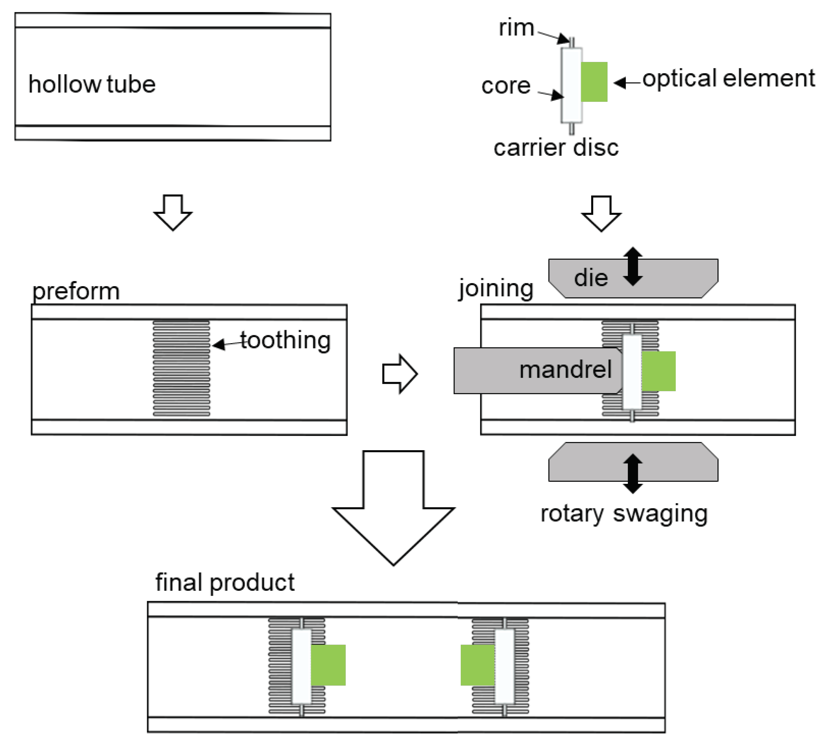
As can be seen in Figure 2, the sensor elements are fixed to a disc consisting of a thick core and a relatively thin rim. The tube is pre-toothed at the pre-defined joining position. The purpose of this approach is to create areas of low stiffness in the two joining partners. This allows for a form-fit joining with relatively low joining forces. At the very beginning of the joining process, the disc is firmly positioned inside the tube and can withstand further forming steps. By utilizing a mandrel, the disc is positioned inside the tube and fixed within during the rotary swaging process. In this case, the stiffness ratio between the rim and the toothed tube determines the degree of the desired form- and force-fit joining.
3. Numerical process simulation
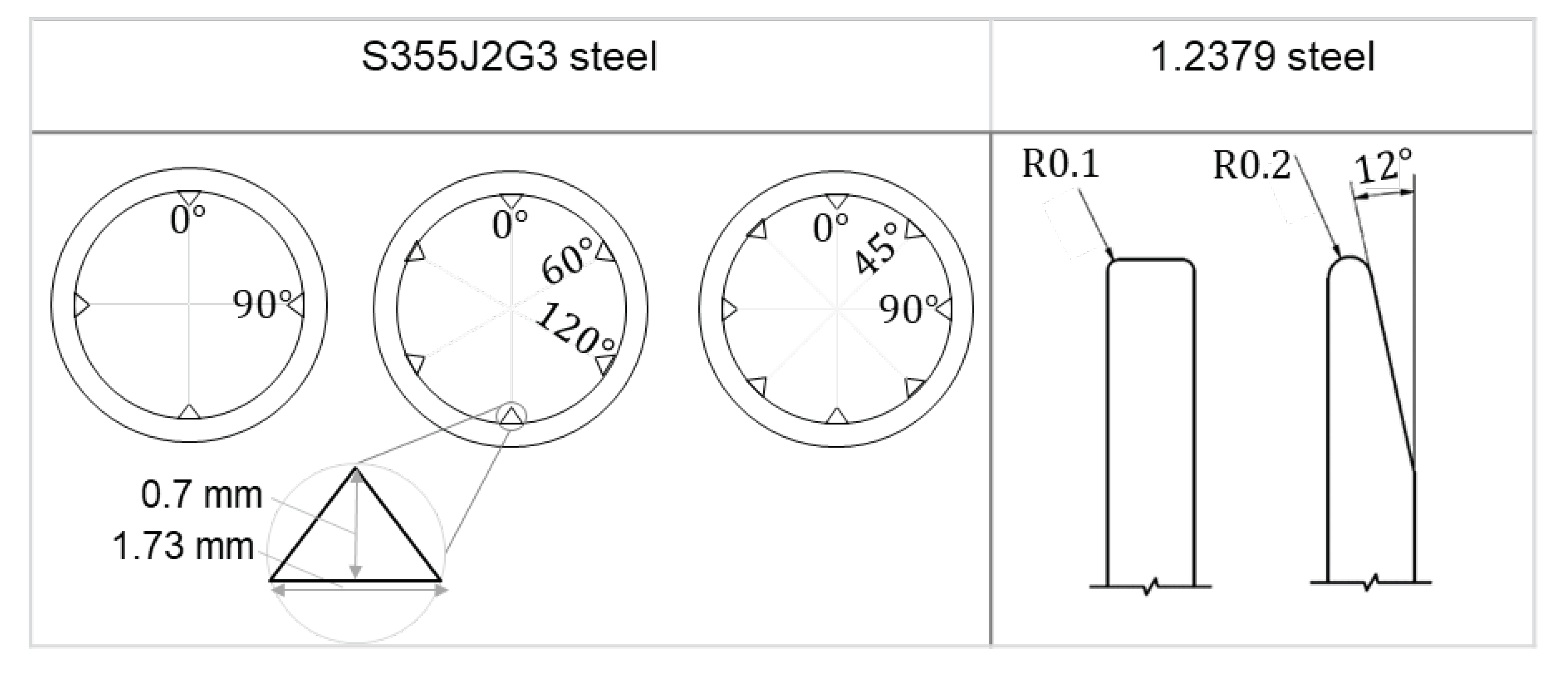
The stiffness ratio between the components being joined can be influenced by their material properties or geometric design. To prevent premature plastic deformation of the rim as it engages with the tooth, the disc is assumed to be constructed from 1.2379 steel with a high yield strength (σ_y = 420 MPa), while the tube is made of S355J2G3, which has a relatively lower yield strength (σ_y = 355 MPa). The numerical simulation considered two configurations for the rim edge: one with a chamfered edge and one without. The number of teeth was also varied, with configurations featuring 4, 6, and 8 teeth, as detailed in Table 1.
Table 1 shows the simulated parameters of the joining partners. The tooth has a height of 0.7 mm, a base of 1.73 mm, and a flank angle of 100 °. The integration is simulated with 4, 6 and 8 teeth. The sensor-bearing disc consists of a core diameter of 10 mm and a rim diameter of 22 mm. The disc edge is simulated as chamfered and not chamfered. Increasing the number of teeth increases the required force for the disc penetration and reduce the form-fit of the joint. A similar behavior can be observed when increasing the contact surface on the disc’s rim. With the aid of numerical investigations, the geometric design of the carrier disc and the internal toothing are analyzed with respect to the resulting force and the form-fit.
To set up the simulation model, preliminary investigations are driven upon a small segment of the entire model using the explicit Abaqus solver. Furthermore, to reduce the computational time for the numerical investigation of the complex rotary swaging process, only 10 tool strokes are set to achieve the final diameter reduction. Since torsional loads occur during workpiece rotation when the forming tools are closed during rotary swaging, the influence of torsion during rotary swaging is neglected and the simulation model is set up for torsion-free rotary swaging of the tube, so that the workpiece only rotates when the tools are open, Figure 4, (b).
3.1. Preliminary simulation and basics of model parameters
Due to the high deformation of the teeth during the disc penetration, the mesh shape and the mass scaling need to be optimized to improve the accuracy of the simulation. In a standard Abaqus mesh algorithm, the inner elements become very small in a triangular shape, like a tooth. As a result, these elements become completely flat at larger deformations and the simulation will be aborted. In order to avoid this problem, internal paths with specific node distribution are created. Figure 3 a shows the standard mesh at the top with internal elements getting smaller and the created mesh with the designed nodes paths in red at the bottom. Furthermore, the Arbitrary Lagrangian-Eulerian Algorithm for remeshing (ALE) was used to create a more uniform aspect ratio within the mesh. Figures 3b and c show the simulation parameters and the resulting deformation behavior during the joining process.
The different materials allow the tooth to undergo plastic deformation earlier, making it easier for the rim to penetrate. When the rim reaches the bottom of the tooth, the compressive stress increases and the rim begins to deflect, see Figure 3c. To accurately simulate the joining behavior of the disc between the teeth and the disc, a 3D section with a thickness and a height of 5 mm of the tube is modeled, Figure 4a. This allows the joining behavior to be modeled with higher accuracy in both the axial and radial directions. The modeled tube section includes a variable number of teeth, the carrier disc and the four tools.
Figure 4.
a) Model setup for the simulation of the design parameters and b) tool kinematics.
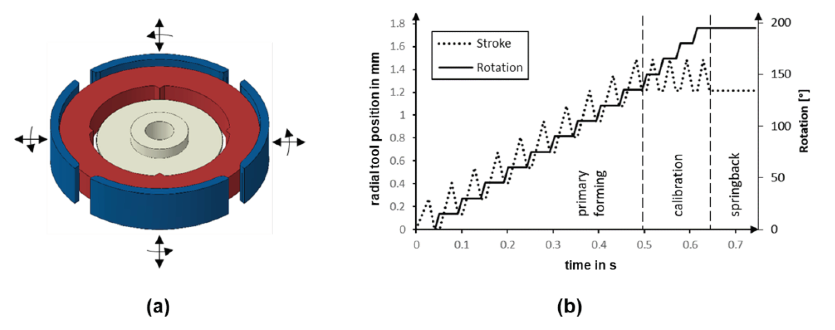
Figure 4, (b) shows the movement of the tools. After ten forming strokes, four calibration strokes are carried out to ensure a uniform stress distribution between the disc and the tube teeth. At the end of the forming process, the boundary condition that fixes the disc is removed. Due to the stress relief and the resulting springback, the disc reaches its final position.
3.2. Investigating the effect of the rim geometry
As shown in Table 1, the influence of the geometry of the rim edge is investigated by comparing two main variants: a chamfered and a non-chamfered rim edge. In the non-chamfered rim edge variant, the contact surface is twice as large as in the variant with the chamfered edge. Therefore, it is expected to require a higher radial joining force and achieve a lower penetration depth in this case.
In addition to evaluating the deformations, the force fit is also analyzed using the radial stress. The simplifying assumption is made that after the integration of the carrier disc, only radial stresses appear at the boundary between the thick core and the rim, as visualized in Figure 5b.
The evaluation of the penetration depth shows that the chamfered rim achieves only about 10 % higher penetration depth (Figure 5a) and about 3 % lower maximum radial stress (Figure 5b) compared to the non-chamfered edge. However, a significant difference can be observed in the axial deflection behavior of the two rim geometries shown in Figure 5c.
As can be seen in Figure 5c, both disc variants show a wave-like axial deflection with peaks at the teeth resulting from disc penetration. However, the chamfered variant shows significantly higher peaks. An increased alternate rim deflection between the toothed and non-toothed areas indicates a higher axial disc grip within the teeth. Both disc variants are subjected to nearly identical radial and axial forces, whereby the radial force results from the radial forming tools and the axial force results from the material flow in the axial direction. However, the chamfered rim variant experiences a higher axial deflection due to the chamfer geometry, see Figure 5d. Due to the higher penetration depth and the correlated increase in alternate axial rim deflection, the chamfered disc variant is considered in subsequent investigations.
3.3. Investigating the number of teeth
Increasing the number of teeth obviously increases the contact area between the teeth and the disc, which increases the required joining force and decreases the achievable penetration depth. To investigate the effect of the number of teeth on the formation of the joint, the number of teeth is varied between 4, 6 and 8 in the following tests. In this variant, the disc with the chamfered rim was used. The simulation results show no significant differences in the depth of the disc penetration, Figure 6a. On the other hand, the radial stress distribution is more dependent on the number of teeth, as can be seen in Figure 6b. The difference in radial stress between four and eight teeth is approximately 40 MPa.
However, the results indicate that increasing the number of teeth seems to lead to unsymmetrical disc penetration into the teeth as well as an inhomogeneous distribution of radial stress on the disc. The radial stress distribution appears to have four distinct amplitudes regardless of the number of teeth. To clarify this behavior, both the disc penetration and the development of radial stress during the rotary swaging process were analyzed. See Figure 7.
The average penetration in all teeth (blue curve) and the deviation in tooth penetration (error bars) are shown in Figure 7 (a) for the three cases. It can be observed, that in the case of four teeth, there is a linear development of the disc penetration at almost the same level in all teeth. In the case of 6 and 8 teeth, the penetration becomes less linear and shows significant deviation between the teeth. This deviation is even more distinct in the case of the 6 teeth and the progression of the penetration appears to be more non-linear.
The reason for this behavior was identified as radial force propagation from the tools into the tube during the rotary swaging process. Since only four oscillating tools strike the tube each time, some of the teeth are located outside the path of the acting radial force. At this point, the tube material starts to flow in the unloaded gap between the tools, causing the previously established radial stress to be released. Figure 7 (b) illustrates the material flow at three teeth for the case of 8 teeth during a forming increment.
As can be seen in Figure 7 (b), the axial material flow of the teeth in the area of the gaps between the tools is much higher than for the teeth in the tool engagement zone. This alternating reduction of the previously established radial stress through incremental tool striking and workpiece rotation explains why, regardless of the teeth variants, the resulting stress distribution shows the same pattern. This pattern is determined by the number of the rotary swaging tools.
Although this typically has less effect on the roundness and surface finish of rotary swaging workpieces, it leads to a distortion of the radial stress created between the disc and the die. To mitigate this issue, the teeth should ideally be arranged so that they remain within the effective tool area during rotation.
4. Experimental investigations
4.1. Preliminary trails:
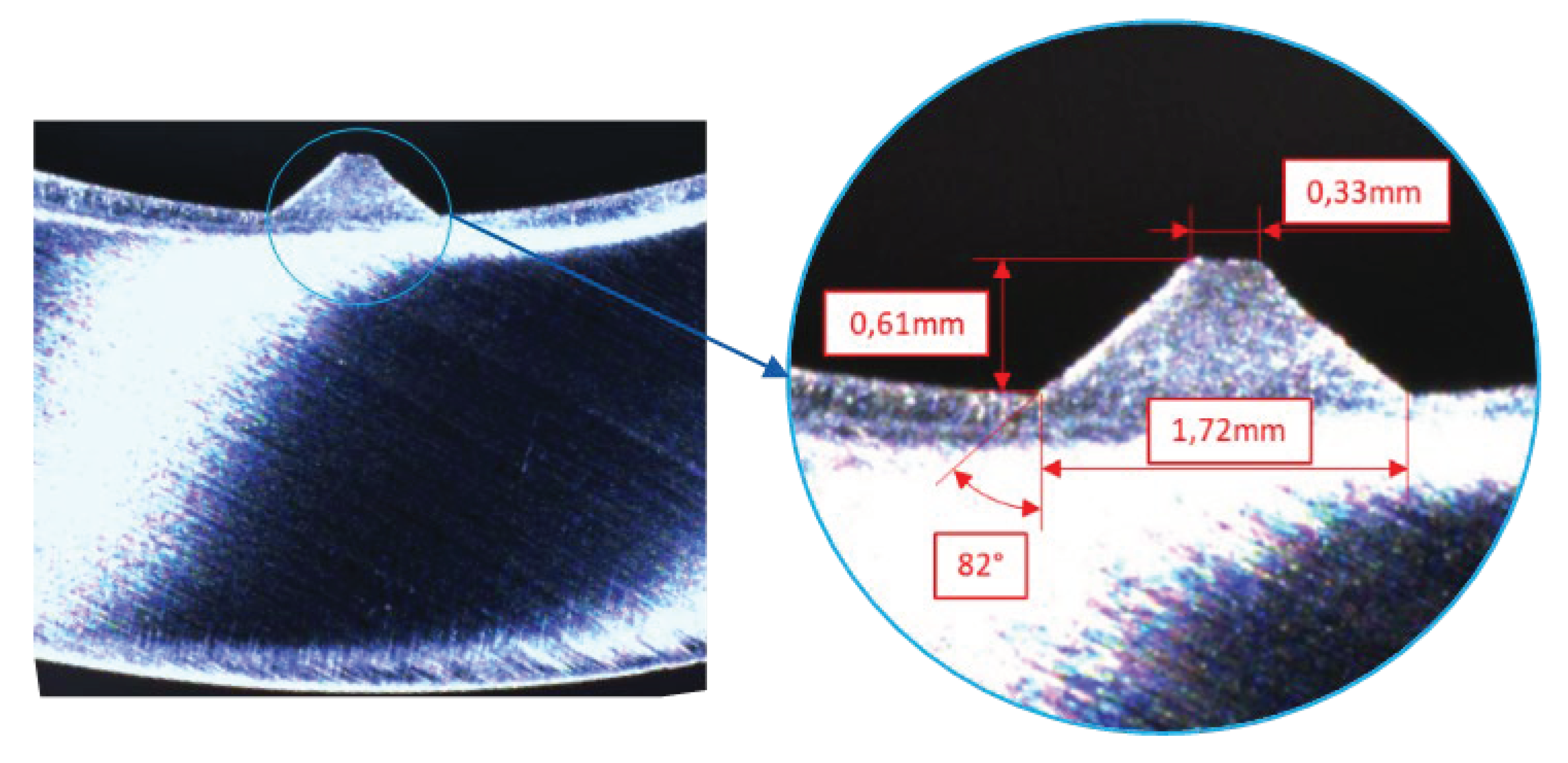
In this work, the internal toothing of the tube is created by rotary swaging. A mandrel with toothed cavities is inserted into the tube during rotary swaging. As the rotary swaging proceeds, the material flows into these cavities, forming the internal teeth. The tube was pre-toothed with 8 teeth, due to the higher achievable radial stress. The following figure presents a cross-section of the resulting tooth geometry.
Figure 8.
Cross section of the resulting tooth geometry.
After the tube is toothed, the discs are attached to a mandrel and positioned within the pre-toothed section inside the tube. The tube diameter is then reduced by infeed rotary swaging and the disc is joined inside the tube. The disc-fixing mandrel is designed to move freely along the axial direction, allowing for axial displacement of the disc following initial penetration and preventing excessive rim deflection. Subsequently, the quality of the joint is determined visually using metallographic cross-section images. In addition to the penetration depth t, the deflection of the disc a is also evaluated as a characteristic of the force-fit joining. To prevent springback during cutting, the specimens are fully embedded in resin. As can be observed in Figure 9a, the disc undergoes considerable axial compression as a result of the radially acting joining force with a minimal deflection of a = 1.1 mm and a penetration depth of t = 0.35 mm. Comparing the deformation behavior of the disc between the simulation and the experimental results in Figure 9d, shows a higher plastic deformation at the contact regions with the teeth in the experiment. This is attributed to not considering the strain hardening effect in the teeth during the preforming process. As the simulation primarily focused on analyzing the penetration behavior of the disc into the teeth and due the challenges associated with mesh generation, as discussed in Section 0, the pre-toothing process was not considered in the simulation.
4.2. Sensor integration
After successfully integrating the two discs with attached optical elements into the tube, experiments were carried out to join two discs with a specific distance between them. For a set distance of 80 mm between the two discs, a distance of 79.6 mm was achieved after joining. However, the two discs were tilted by 0.8° relative to each other, which is still not tolerable for the optical sensor. This tilting would affect the mirrored beam, preventing the reflected light beam from reaching the image sensor. The observed disc tilt might be caused by a non-symmetrical forming of the tube due to tiny deviations in the timing of the strokes of the different tool segments or because the wall thickness is not perfect uniform. Since the alignment of the two mirrors to each other has the tightest tolerance in the designed sensor (Figure 1), the design was simplified to measure only in-plane displacement (torsion and bending loads) and the mirrors were removed. Figure 10 shows a successfully integrated optical sensor along with a schematic illustration of the sensor.
The integrated sensor is used to non-destructively evaluate the quality of the joint. The sensor tube is subjected to three-point bending and torsional load on testing machines, which is detected by the integrated sensor. An inadequate joint would result in a hysterical behavior or a zero-point shift in the sensor signal. The tube is incrementally loaded with a maximum bending force of 1500 N and a maximum torsional load of 300 Nm. During the bending test, the load is applied in the midpoint between the two integrated discs.
Figure 11.
Sensor behavior of the forming integrated optical-based sensor under a) torsional load and b) 3-point bending load.
Figure 11.
Sensor behavior of the forming integrated optical-based sensor under a) torsional load and b) 3-point bending load.
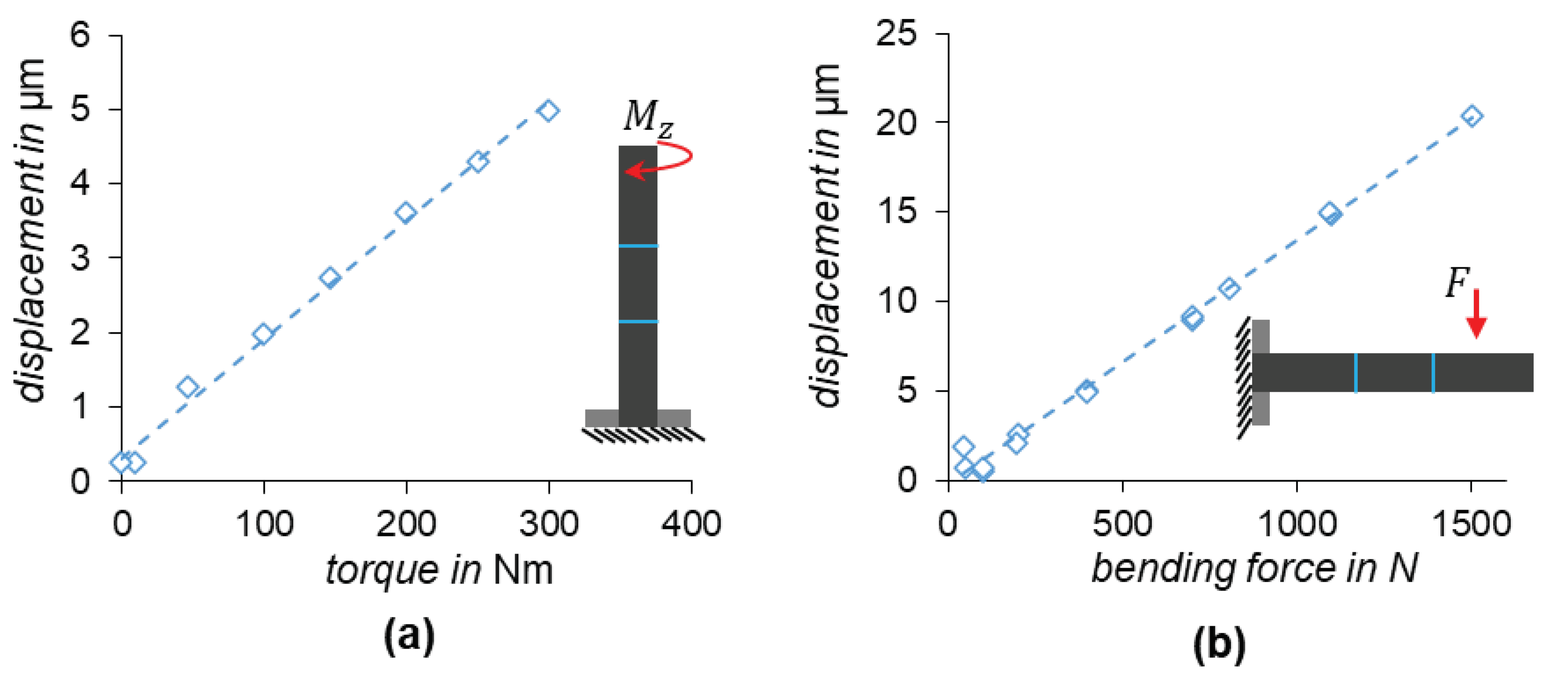
Both sensor signals in Figure 11 show hysteresis-free and zero-point stable behavior, confirming a successful integration.
5. Approach for position-controlled sensor joining controlling the disc tilting
Ensuring the required parallel alignment of the built-in mirrors in the presented sensor design (Figure 1) is the key challenge during integration into the tube. To address this challenge, it is imperative to prevent or control possible disc tilting during the rotary swaging process through the implementation of a closed-loop controller. In essence, closed-loop position control requires both in-process measurement of the actual position and the ability to manipulate it. Assuming that the built-in sensor can detect position deviations occurring between the two discs, the use of the 3D Servo Press (3DSP) as a 3D press with three degrees of freedom in ram motion [16] offers a promising approach for implementing position-controlled disc joining. This possible approach is discussed below.
5.1. Process design
To achieving position-controlled disc joining is to use the integrated image sensor to detect positional deviations in three dimensions, e.g. disc tilt, by analyzing image contrast values in different regions. The 3D ram motion of the 3DSP is then used to adjust the disc position, thereby correcting any deviations along the z-axis or tilting in the x-y plane.
To achieve this approach, we designed a new compact rotary swaging machine for use within the 3DSP, see Figure 12b. The machine includes separate controlled drives for tool rotation and radial motion, which allows for torsion-free tool swaging.
As shown in Figure 12, a mini rotary swaging unit is placed inside the 3DSP to swaging the tube. The disc is mounted to the ram of the 3DSP via a mandrel. A deviation in the reference position between the two discs xref. is determined by the image contrast over the whole image and calculated into the corresponding ram position via a pre-trained CNN model. This is fed into the ram controller of the 3DSP, where the actual position is determined by an observer.
5.2. Numerical process simulation and results
Numerical simulations were conducted to investigate the possibility of compensating for disc tilting and to examine the available time window for correcting the disc position during disc joining. In the numerical investigation, the disc is initially tilted by , 1° and . See Figure 13a. For an initial tilt of 1 °, a disc tilt is corrected at four different process advance times, which is driven from the previous investigations. See Figure 13b. Figure 13c shows the results for an initial tilt of 2 ° for two candidate process times.
As can be seen in Figure 13, the simulation results demonstrate that the earlier the misalignment is corrected and the smaller the error is, the smaller the remaining angle error. The stiffness ratios between the two joining partners ensure a form-fit connection despite the subsequent change in position for tilt correction.
6. Conclusions
In this study, we investigated the possibility of integrating highly sensitive optical sensors with the required high positional accuracy using rotary swaging. The investigations have demonstrated the possibilities offered by appropriate design of the joining parameters and the joining process. Additionally, the studies have shown that the number of tools and the contact area during rotary swaging directly affect the distribution of radial stresses in the integrated disc. When a tooth is located in the gap between the tools during a forming increment, the material flow at that point results in a partial reduction of the previously created radial stress. As the tube rotates and the gap between the teeth changes, a non-linear radial stress is created that increases with the depth of penetration. The integration of two discs at a specific distance to each other resulted in a deviation of only 0.6 % from the desired distance, but the total tilt of the discs of 0.8 °. To permit higher tilting, the sensor carrying discs required a simplification of the optical sensor design to ensure its functionality. Full functionality with no hysteresis is provided by the integrated sensor for bending force and torque measurement. To achieve higher positional accuracy during the disc joining process, the paper has presented a possible approach for a position-controlled disc joining by means of the 3DSP to improve the achievable positional accuracy. Numerical results show a potential to correct possible angle tilt errors during the joining process. In future work, this control approach will be implemented and experiments will be conducted.
References
- L. M. Alves, F. L. R. Silva, R. M. Afonso, and P. A. F. Martins, “A new joining by forming process for fixing sheets to tubes,” International Journal of Advanced Manufacturing Technology, 2019. [CrossRef]
- K. I. Mori, N. Bay, L. Fratini, F. Micari, and A. E. Tekkaya, “Joining by plastic deformation,” CIRP Annals - Manufacturing Technology, 2013.
- A. Schubert, V. Wittstock, S. F. Jahn, B. Müller, and M. Müller, “Joining by forming of piezoceramic macro-fiber arrays within micro-structured surfaces of aluminum sheets,” Production Engineering, 2014. [CrossRef]
- L. M. Alves, C. M. A. Silva, and P. A. F. Martins, “End-to-end joining of tubes by plastic instability,” Journal of Materials Processing Technology, vol. 214, no. 9, pp. 1954–1961, Sep. 2014. [CrossRef]
- L. M. Alves, R. M. Afonso, C. M. A. Silva, and P. A. F. Martins, “Boss forming of annular flanges in thin-walled tubes,” Journal of Materials Processing Technology, vol. 250, pp. 182–189, 2017. [CrossRef]
- N. Al-Baradoni and P. Groche, “Sensor-integrated structures in mechanical engineering: challenges and opportunities for mechanical joining processes,” Production Engineering, vol. 16, no. 2–3, pp. 423–434, 2022. [CrossRef]
- M. Brenneis, M. Türk, and P. Groche, “Integration of smart materials by incremental forming,” in Applied Mechanics and Materials, 2012. [CrossRef]
- P. Groche and M. Krech, “Efficient production of sensory machine elements by a two-stage rotary swaging process—Relevant phenomena and numerical modelling,” Journal of Materials Processing Technology, 2017. [CrossRef]
- M. Krech, A. Trunk, and P. Groche, “Controlling the sensor properties of smart structures produced by metal forming,” Journal of Materials Processing Technology, 2018.
- N. Al-Baradoni, M. Krech, and P. Groche, “In-process calibration of smart structures produced by incremental forming,” Production Engineering, 2020. [CrossRef]
- M. Krech, Adaptive forming process for the production and simultaneous calibration of metallic structures with component-integrated force and torque sensors. Adaptiver Umformprozess zur Herstellung und simultanen Kalibrierung von metallischen Strukturen mit bauteil. Düren: Shaker Verlag, 2020.
- N. Al-Baradoni and P. Groche, “Sensor integrated load-bearing structures: Measuring axis extension with dic-based transducers,” Sensors, vol. 21, no. 12, p. 4104, Jun. 2021.
- N. Al-Baradoni and P. Groche, “Sensor-integrated structures in mechanical engineering: challenges and opportunities for mechanical joining processes,” Production Engineering, vol. 16, no. 2–3, pp. 423–434, Jan. 2022. [CrossRef]
- N. Al-Baradoni and P. Groche, “Sensor Integrated Load-Bearing Structures: Measuring Axis Extension with DIC-Based Transducers,” 2021.
- N. Al-Baradoni and P. Groche, “Identification of the sensory properties of image-based multi-axis force/torque sensors,” in Sensors and Measuring Systems; 21th ITG/GMA-Symposium, 2022, pp. 1–6.
- P. Groche, F. Hoppe, and J. Sinz, “Stiffness of multipoint servo presses: Mechanics vs. control,” CIRP Annals - Manufacturing Technology, 2017.
Figure 1.
Schematic design of the optical sensor [15].
Figure 1.
Schematic design of the optical sensor [15].
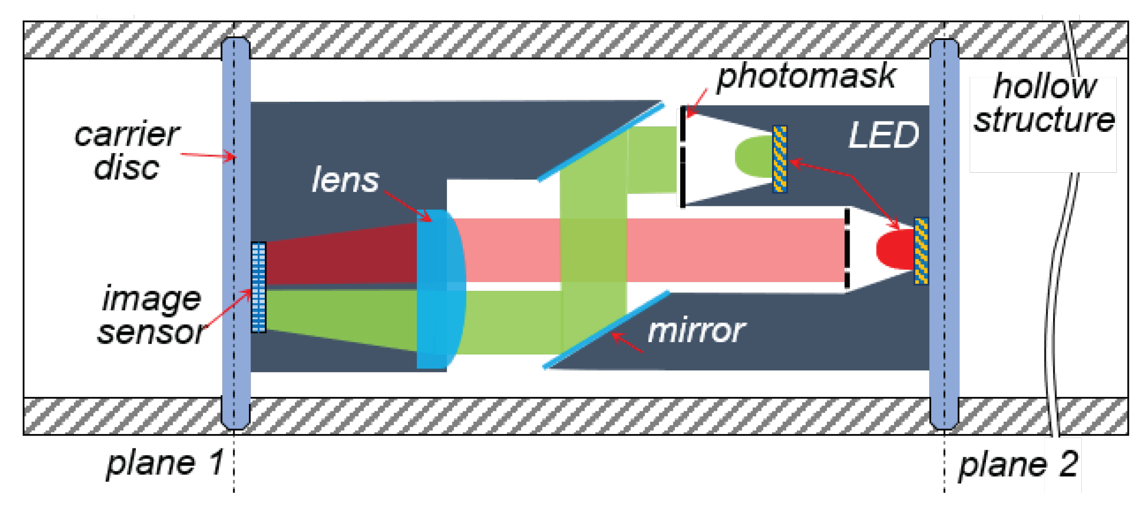
Figure 3.
Preliminary simulation and basics of model parameters. a) tooth mesh design, b) simulation set parameters and c) achieved disc penetration behavior .
Figure 3.
Preliminary simulation and basics of model parameters. a) tooth mesh design, b) simulation set parameters and c) achieved disc penetration behavior .
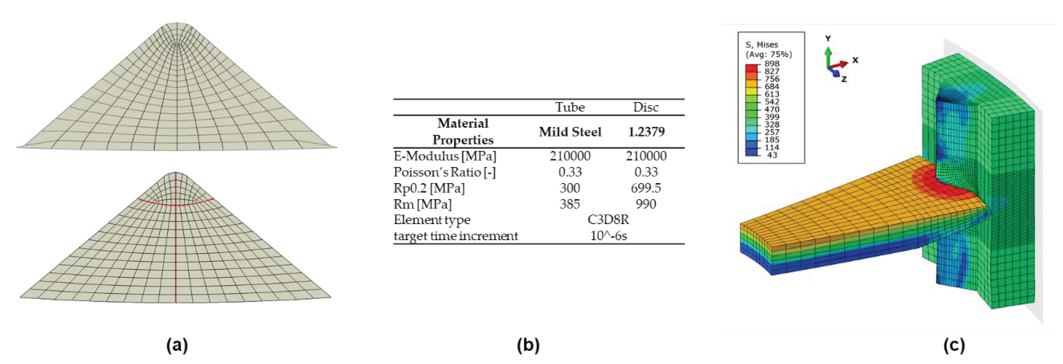
Figure 5.
Effect of rim edge on the joining process, a) on the depth of penetration, b) on the radial joining force, (c) axial edge deflection over the whole disc circumference and (d) visualization of the influence of the chamfer on the force distribution at the rim.
Figure 5.
Effect of rim edge on the joining process, a) on the depth of penetration, b) on the radial joining force, (c) axial edge deflection over the whole disc circumference and (d) visualization of the influence of the chamfer on the force distribution at the rim.
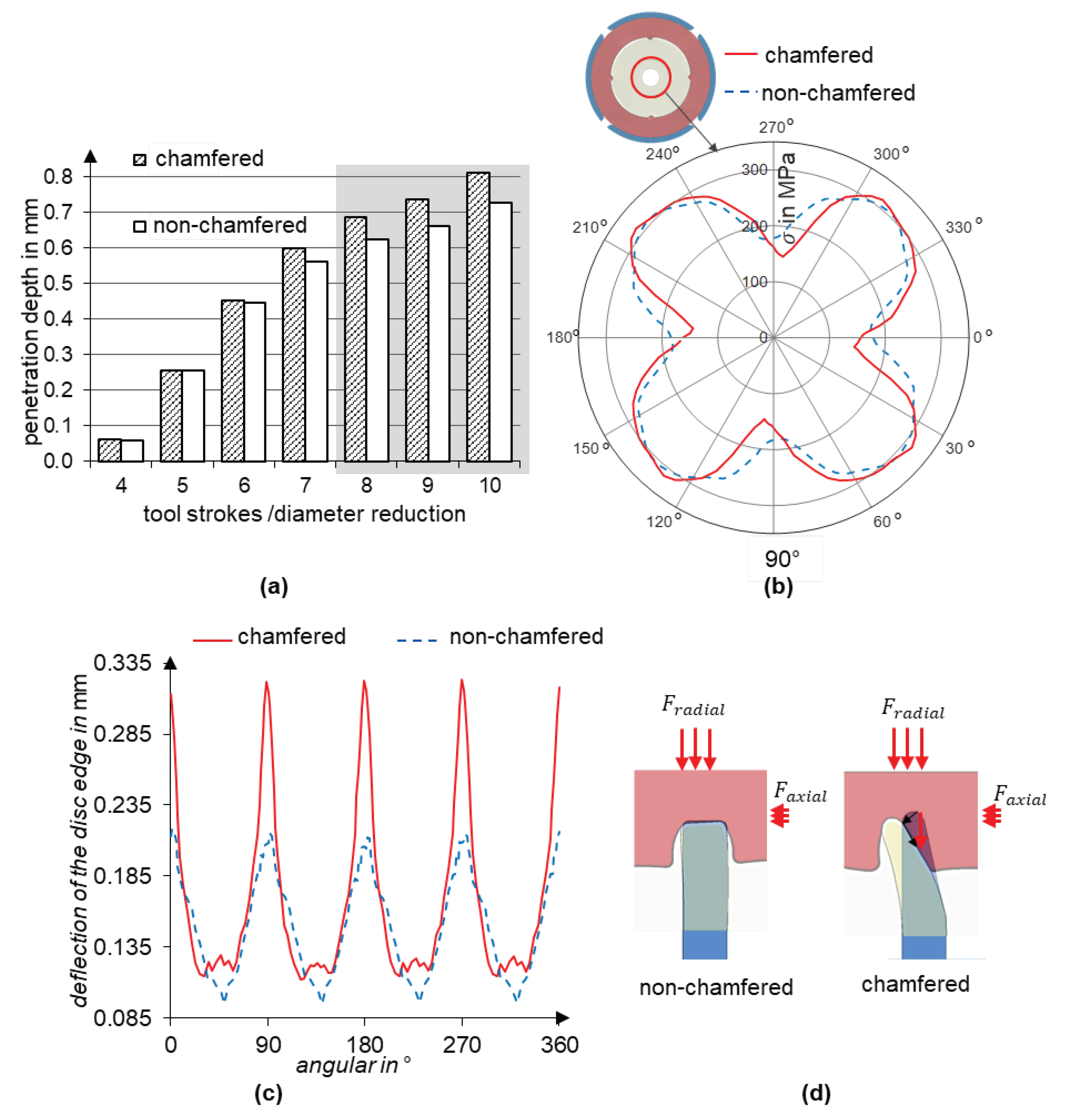
Figure 6.
Effect of number of teeth on the joining process a) on the penetration depth at the teeth, b) on the radial stress distribution at the disc.
Figure 6.
Effect of number of teeth on the joining process a) on the penetration depth at the teeth, b) on the radial stress distribution at the disc.
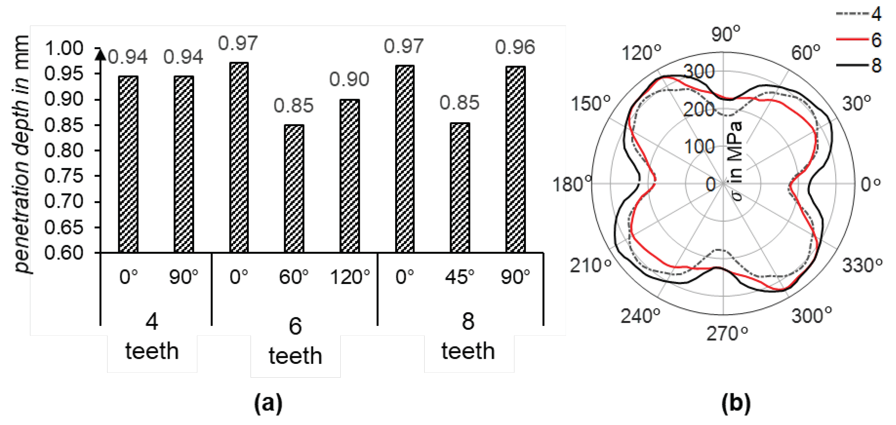
Figure 7.
Formation of the joining during tube rotary swaging. a) disc penetration in the last three increments for the teeth variation and b) axial material flow at the teeth during the swaging process.
Figure 7.
Formation of the joining during tube rotary swaging. a) disc penetration in the last three increments for the teeth variation and b) axial material flow at the teeth during the swaging process.
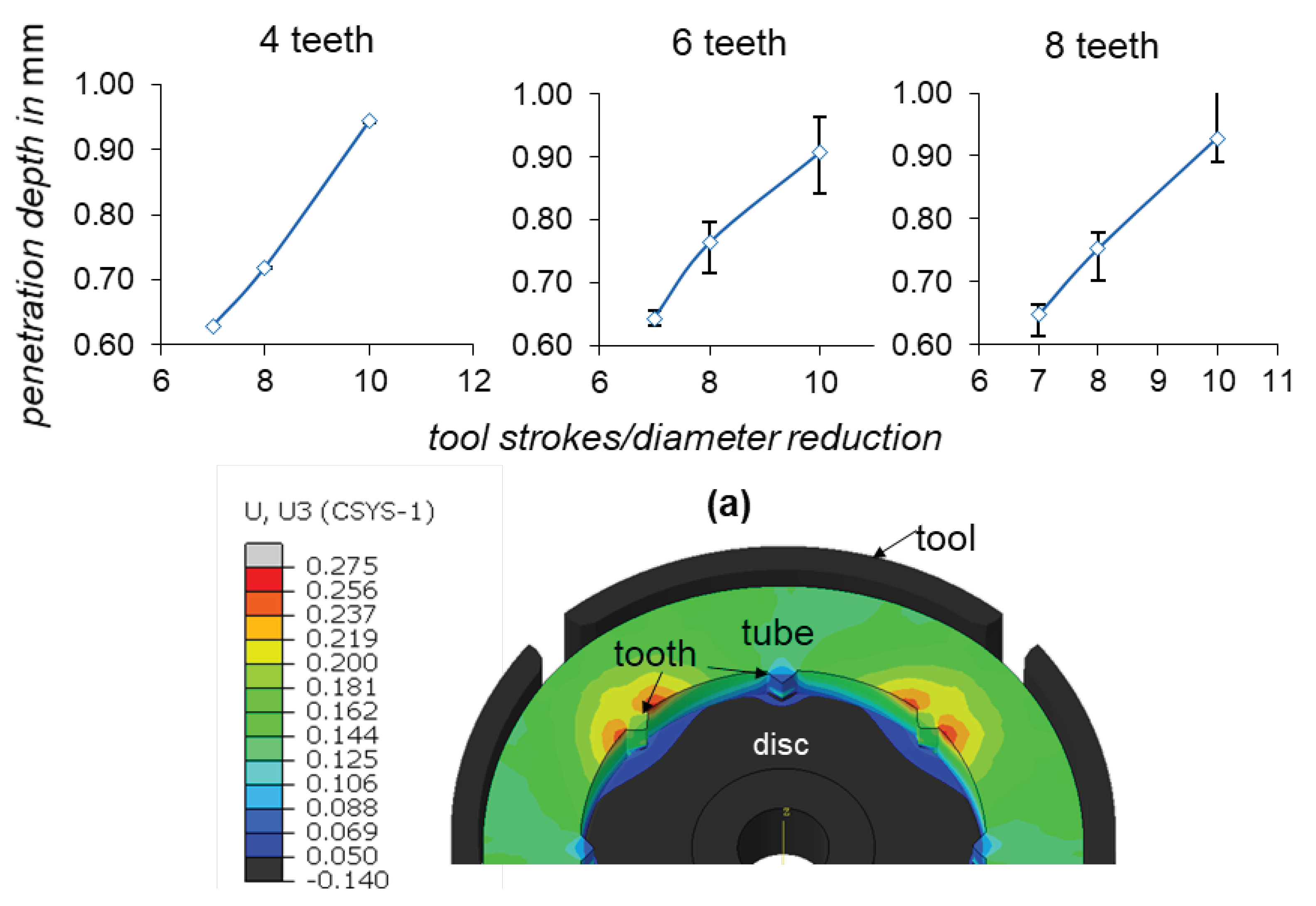
Figure 9.
Successful disc integration into the tube. (b) and (c) Integrated disc inside the tube, (a) cross-section images of the integrated disc and (d) deformation behavior compared to the simulation.
Figure 9.
Successful disc integration into the tube. (b) and (c) Integrated disc inside the tube, (a) cross-section images of the integrated disc and (d) deformation behavior compared to the simulation.
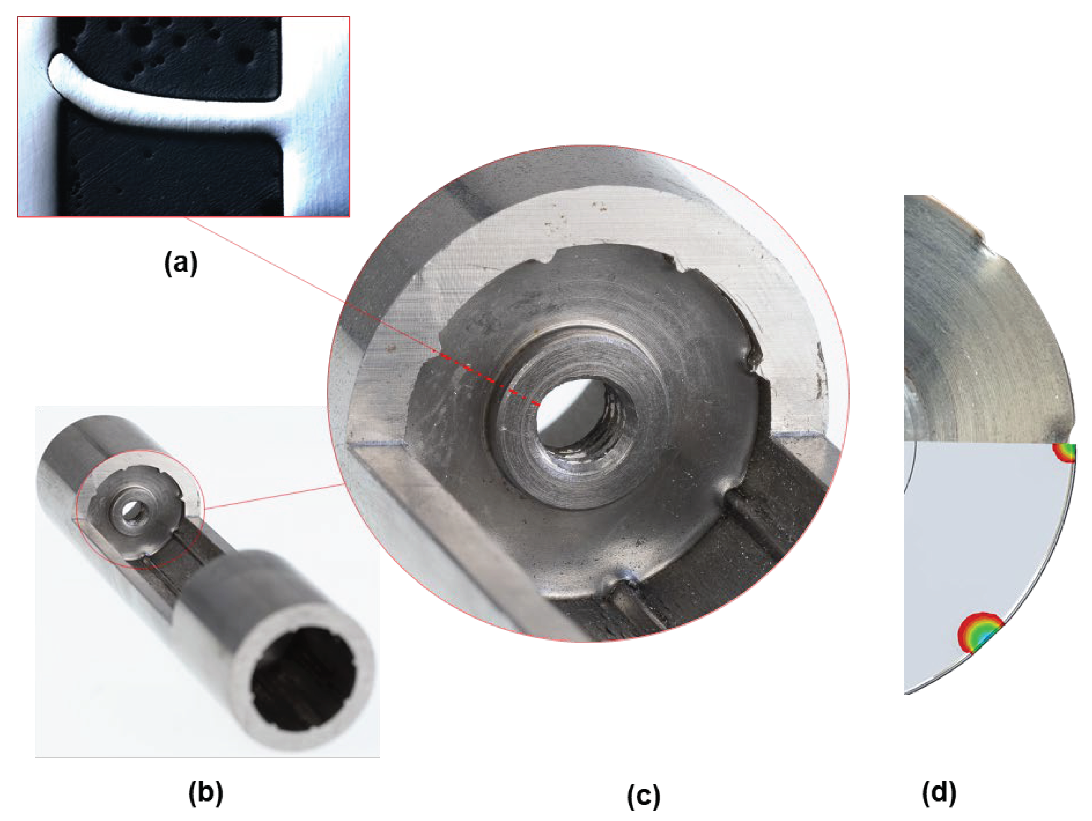
Figure 10.
Successfully integrated optical sensor for measuring bending and torsional loads with an illustration of the integrated sensor.
Figure 10.
Successfully integrated optical sensor for measuring bending and torsional loads with an illustration of the integrated sensor.
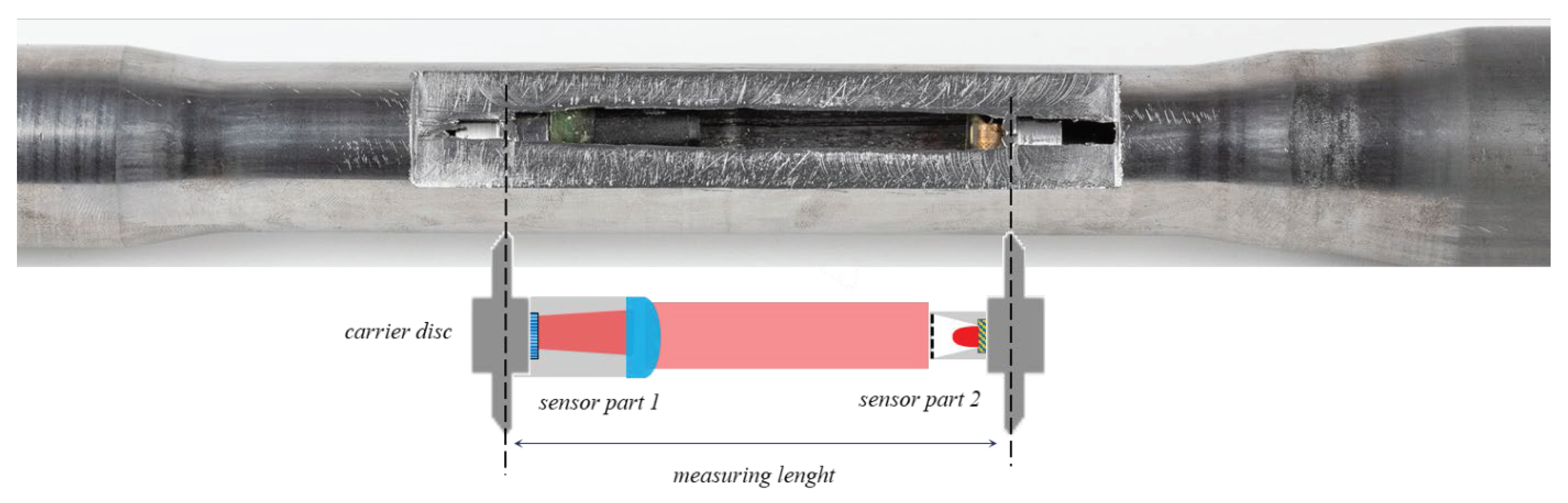
Figure 12.
Process design for position-controlled sensor integration. (a) schematic visualization, (b) rotary swaging unit, (c) 3DSP and (d) control strategy.
Figure 12.
Process design for position-controlled sensor integration. (a) schematic visualization, (b) rotary swaging unit, (c) 3DSP and (d) control strategy.
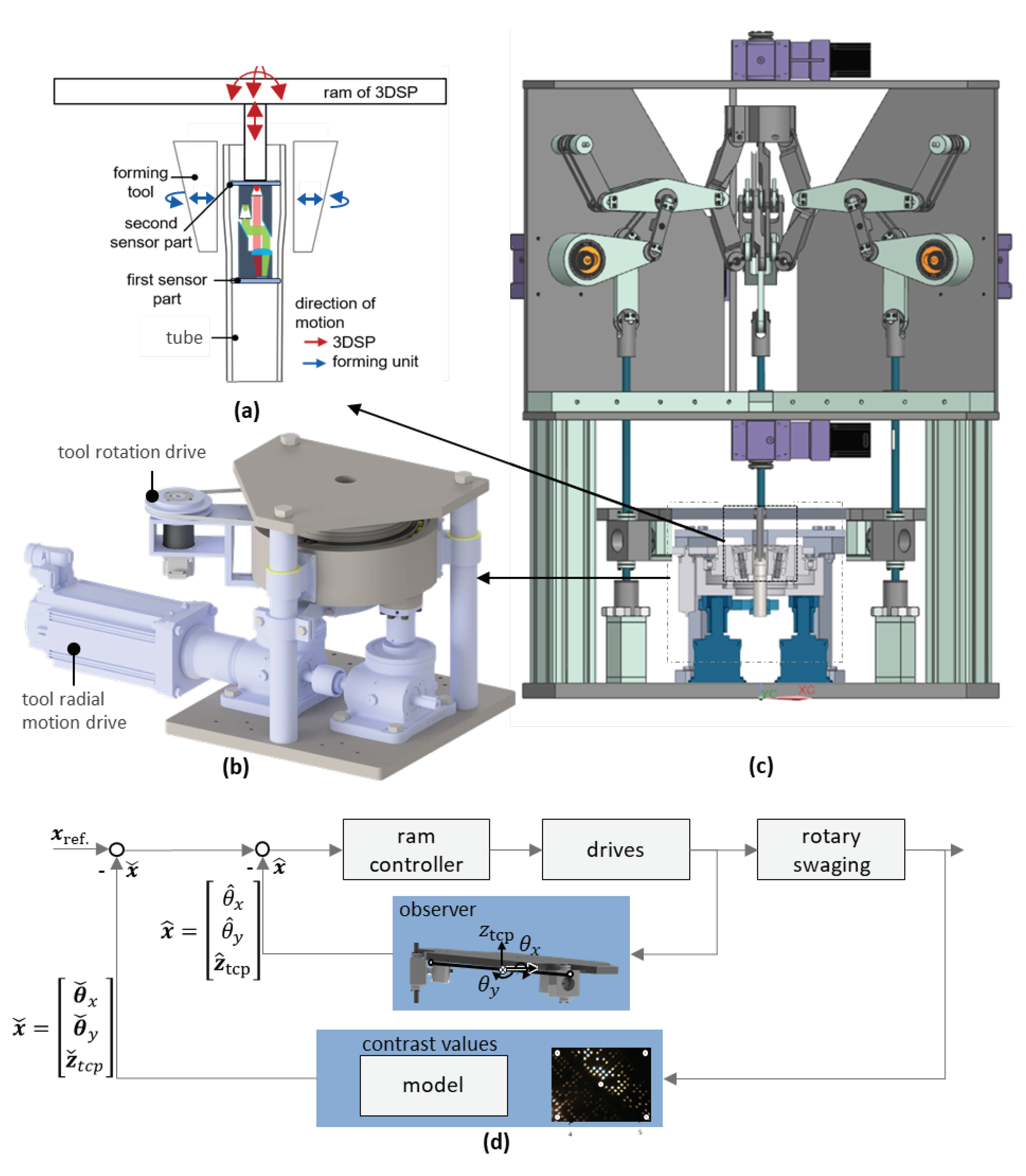
Figure 13.
Simulation position-controlled disc integration. Simulation model set-up (a) and remaining titling after tilt correction at different process stages for initial error of 1° (c) and 2° (d).
Figure 13.
Simulation position-controlled disc integration. Simulation model set-up (a) and remaining titling after tilt correction at different process stages for initial error of 1° (c) and 2° (d).
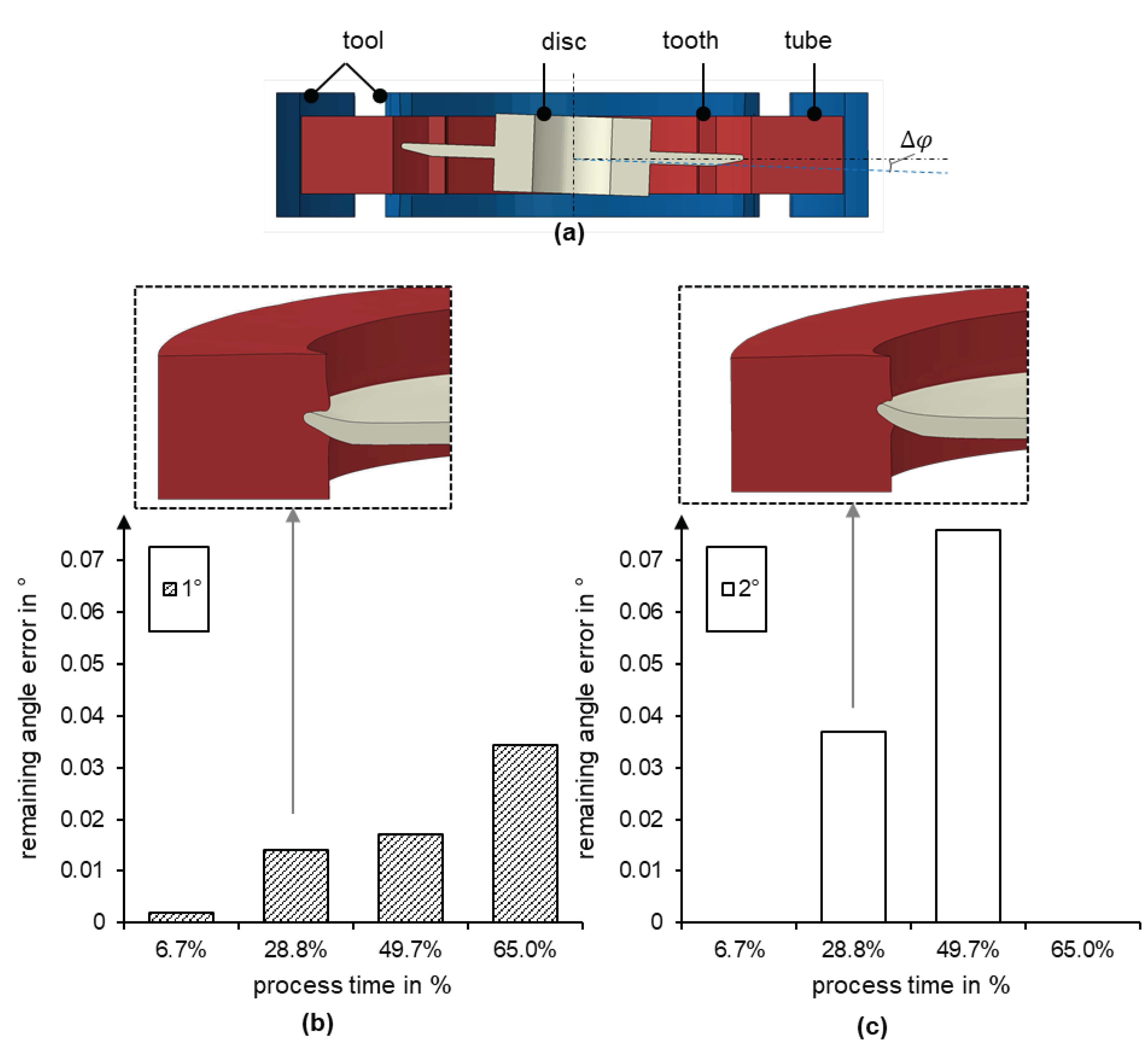

Table 1.
Material and parameter variation for both joining partners.
Disclaimer/Publisher’s Note: The statements, opinions and data contained in all publications are solely those of the individual author(s) and contributor(s) and not of MDPI and/or the editor(s). MDPI and/or the editor(s) disclaim responsibility for any injury to people or property resulting from any ideas, methods, instructions or products referred to in the content. |
© 2024 by the authors. Licensee MDPI, Basel, Switzerland. This article is an open access article distributed under the terms and conditions of the Creative Commons Attribution (CC BY) license (http://creativecommons.org/licenses/by/4.0/).
Copyright: This open access article is published under a Creative Commons CC BY 4.0 license, which permit the free download, distribution, and reuse, provided that the author and preprint are cited in any reuse.


