
Submitted:
08 February 2024
Posted:
09 February 2024
You are already at the latest version
Abstract
In the paper, a study of the performance of unmanned ground vehicle (UGV), establishes numerical simulation model of the chassis system by three-dimensional software and finite element analysis software. Based on the numerical modelling and analysis, the work focuses on study of the strength and stiffness of the vehicle's chassis and researched the distribution of stress and deformation under the extremal condition. The paper also presents an autopilot design with new cascade control system for an autonomous motion of an unmanned ground vehicle based on Proportional-Integral-Derivative (PID) and Feed-Forward (FF) control. The PID-FF controller is a part of dedicated for presented UGV used in a hybrid control system for precise control and stabilization, necessary to increase the vehicle motion stability and maneuvers precision. The hybrid PID-FF control system proposed for the ground vehicle model gives a satisfactory quality of control, while maintaining the simplicity of the control system. Presented tests performed in area of mechanical design and control analysis gives good results and proves usefulness of designed unmanned device.
Keywords:
finite element method
; mechanical stress and deformation
; airport pavement
; unmanned ground vehicle
; autopilot
; proportional-integral-derivative control
; feedforward control
1. Introduction
The use of autonomous robotic systems such Autonomous Unmanned Ground Vehicles (UGV) in the military world has increased, especially for air and land forces. UGV integrate modern technology into civil or military units, by sensing the environment through remote management or by means of sensor systems, and performing basic tasks within the scope of the requirements. Autonomous UGVs, which are available in different sizes and configurations for different needs, have gained qualities that can fulfill many tasks. One of these is airport industry and airport technology (e.g., surface imaging, defects detection, pavement testing, surface assessment etc.), the incorporation of new, hi-tech platforms is constantly growing in civil and military engineering research [1,2,5]. Engineers still planning to target the airport industry as a commercial market for unmanned ground vehicle (UGV) system, especially dedicated for pavement testing and surface assessment [3,4]. Routine inspection and maintenance of pavement surface is of utmost importance, especially in runway strips designed for take-off and landing of aircrafts at significantly higher speeds.
Airport UGVs should ensure a precise assessment of the load-bearing capacity of natural airport surfaces in a continuous way. This specific type of surface occurs at airports and airstrips for private, civil and military use [23].
Natural airport surfaces share one goal: minimization of the negative impacts when an aircraft uses an Airport Functional Element (AFE). Therefore, there is an urgent need to design and implement an autonomous, unmanned measuring device that will continuously determine the load capacity of natural airport surfaces, and thus increase the safety of flight operations [21]. A thorough review of some of the existing strategies for pothole detection along highways was conducted by [16,20]. There are four types for sensor modalities – vibration-based, vision-based, thermography-based, and LiDAR-based – to acquire data for pavement inspection. In case of vibration-based methods, authors of work [19] developed a specialized data acquisition hardware mounted on a vehicle for conducting preliminary evaluation of pavement conditions related to potential cracks along pavement surfaces. Also in [17], researchers developed a Pothole Patrol method for detecting and reporting surface conditions of runaways. In the vision-based area for pothole detection, the work [15] proposed an unsupervised vision-based method for pothole detection, without any requirement for additional filtering or training, moreover the authors of [18] proposed an algorithm for pothole detection using stereo-vision.
The paper proposes a new hi-tech UGV called BIZON as an autonomous measuring platform to determine load bearing capacity of natural airport runway pavements and pavement layers from unbound mixtures. Figure 1 shows UGV BIZON views.
The vehicle dedicated to pavement measure of natural airport surfaces using three-wheeled mechanical system. The system consists of one measuring wheel that immerse in the ground pushing for a few centimeters groove with controlled hydraulic pressure. The pressure is scaled in a pavement ratio. Another two wheels are used as measuring guide wheels and they work within much lower pressure value.
The measuring system is rigidly coupled with the BIZON platform chassis, thus very important from the control and navigation point of view is that the navigation algorithms have been supplemented with software mechanisms to protect a failure of the measurement system during the planned mission. Shortly, the software elements performs a continuous analysis of the measuring wheels actual position by linear encoders inbuilt to hydraulic actuators and the current cruise deviation generated by the control systems. In specific conditions, the measuring wheels are raised up on command of the mission plan operator’s, sometimes caused by the vehicle stop.
The platform also equipped with BZYG - unmanned aerial device, allows the introduction to the geotechnical industry of an innovative method which will be significantly better than currently available methods. The result of the study of the state of the art and analysis of solutions offered by competing entities showed a lack of a product with similar features and functionalities on a global scale.
The state-of-the-art analysis for UGV modelling, control and applications provides a wide spectrum of approaches, both model-free and model-based [22]. In this paper and research, using the advantages of both, we proposed a hybrid method, in which the proportional-integral-derivative with feedforward, shortly writing PID-FF control technique is used to control the UGV’s position and speed, while the suitable introduced FF component will increase the precision level in tracking the UGV. The novelty and added value of our work is the development of an original autopilot conception based on cascade hybrid PID-FF equipped with saturation and filtering subsystem, as well as comparative simulation tests for the problem of stabilization of the device orientation and position.
The paper is organized as follows: In Section 2 the ground vehicle mechanics model with strain simulations is presented. Section 3 contains a description of UGV model considering non-holonomic constraints and autopilot design. UGV used in simulation experiments, their comprehensive report and analysis, one may find also in Section 3. Finally, the conclusion is drawn in Section 4.
2. Mechanical Design and Analysis
2.1. Methodology
Nowadays, there is many software packages to analyze and simulate real engineering problems that are well known under the term, Computer Aided Engineering (CAE). The stress and strains distribution, deformations and displacements of the mechanical system can be obtained using SOLIDWORKS Simulation software module. The module is a good tool for solving mentioned problems through the application of Finite Elements Method (FEM) [7]. It is well known that FEM consists of a numerical technique to find solutions, where distributed model of the system is described by Partial Differential Equations (PDE). In other, FEM is a method for dividing up a very complicated problem into small elements that can be solved in relation to each other. The main features of FEA method are the entire solution domain is divided into small finite segments and over each element the behavior is described by the displacement of the elements and the material law. All elements are assembled together and the requirement of continuity and equilibrium are satisfied between neighboring elements while provided that the boundary conditions of the actual problem a satisfied a unique solution can be obtained to the overall system of algebra equation with large and sparse matrices [6].
In recent years the finite element method has been applied to mechanics problems other than those of structural analysis, i.e., fluid flow and thermal analysis. It has been extended to permit the solution of nonlinear as well as linear problems, those of large deformation geometric nonlinearity and/or material property nonlinearity, for example. It is hard to think of any field in which finite elements are not extensively used to provide answers to problems which would have been unsolvable only a few years ago [6,7].
Briefly describing, the equations in discrete form of the FEM approach are generated from the Galerkin form [8,9]
where b is the vector of external body forces, D is a symmetric positive-definite matrix of material constants, t is the prescribed traction vector on the natural boundary , u is trial functions, is test functions and is the symmetric gradient of the displacement field.
The approach uses the following trial and test functions
where n is the number of the nodal variables of the element, is the nodal displacement vector and is the shape function matrix.
By substituting the approximations, and , into the weak form and invoking the arbitrariness of virtual nodal displacements, equation (1) yields the standard discretized algebraic equation system
where K is the stiffness matrix; f is the element force vector that are assembled with entries of
and
with the strain gradient matrix
where integrations (4) and (5) are performed for assumed finite elements with defined interpolation functions, which define the variation of the displacement matrix within the element and on its surface. Since the displacement vector u must be continuous over the entire region, it follows that the displacements at the common nodes of the internal element boundary of two adjoining elements must be the same and that the functional representations of the displacements over the common boundary must be identical [6,8].
2.2. Numerical Analysis
The main mechanical part of the platform is chassis. The UGV platform chassis works under vertical forces from a two packs of power batteries and hydraulic devices used in the vehicle as a power control system for measuring actuators.
With this assumption the analysis is based on models developed in SolidWorks software package for the stress and deformation computations with the mesh based on tetrahedral elements [7]. Figure 2 shows chassis geometry, where each part is made from steel. Figure 3 shows meshes of mentioned platform chassis component.
For the analysis purpose, an upper vertical load is examined computing chassis deformation and stress. Static simulations are performed for the force that acts on chassis upper elements. Simulations consisted of finding deformations and stress for the force push F=3000kG as shown in figure 4.
Figure 4.
Platform chassis deformation.
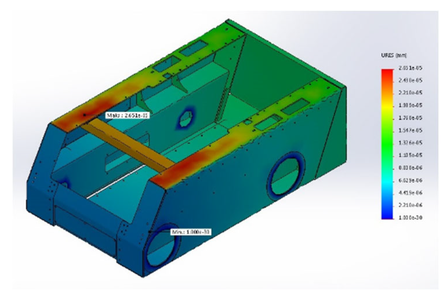
Static analysis performed for each above mentioned case, shows how working forces exciting stress and deformation of analyzed chassis components and indicates areas where the deformation/displacement is most dangerous.
Considering static displacement computation for 3000kg load (presented at Figure 4), as shown, maximum value of displacement is only mm. It means that the construction strongly satisfies its performance.
Another important element of the mobile platform, a set of actuators with fixed beam is examined. The set of actuators creates a platform measuring system for airport pavement testing. Geometry of the subsystem is shown in Figure 5.
The element is very important from the mechanical point of view, because during measurement process the middle hydraulic actuator works with big pressure conditions. The pressure in the actuator reaches 160 bar, but another actuators works also with about 10% of this value. Deformation of applied actuators with mounting beam and fork as wheel support system shows Figure 6.
The result of simulation using SolidWorks software package is shown in Figure 6. Considering static displacement computation for extremal forces working on analyzed beam (left side) shows that maximum value of displacement is equal only 0.56 mm. In case of the fork of wheeled measuring system (right side), the value of maximum displacement is significantly lower and results only about 0.0086 mm. It means that the construction of the measuring system is well designed and can be applied to use in designed UGV platform.
3. Modelling and Control
Small tracked vehicle models [10,11,12] can be approached by differential two-wheeled mobile platforms. A characteristic feature of a two-wheeled vehicle is that it has only two points of contact to the surface. When neglect the slip of the tracks phenomena, then a perfect contact to the ground is achieved. Transformation from tracked vehicle model to the wheeled model is commonly obtained by the virtual wheel method [1,5,12]. Tracked mobile platform approximation employing wheeled platform model with differential drive is simple, more universal and very useful from a control point of view.
3.1. Mathematical Model
As shown in Figure 7, the model of the Bizon platform can be described considering generalized coordinates in global reference frame XY. The body frame origin lies in the center of mass CoM, where a pair describes the CoM position, are angles of right and left wheels and is the platform heading angle.
As described in [22], the mobile platform dynamics can be represented by following motion equation considering friction, Coriolis and centrifugal forces but also non-holonomic constraints:
In Equation (7) is a mass and inertia matrix, is a Coriolis and centrifugal vector
where is the mass of platform base, is the mass of wheels with track, is the substitute wheel radius, is the base moment of inertia, and are moments related to the wheels, is the platform width and is the distance between center of mass and wheels axis. Mass coefficients , , , are defined as follows:
Another matrices in (7) denotes: is a constraints matrix, is a
friction coefficients matrix and is a matrix related to the wheels torques
where , are coefficients related to the linear motion and , are coefficients related to angular speed. Matrix is introduced to omit constraints of the mobile vehicle and performs . The matrix has a following form
Multiplying Equation (7) by
and introducing wheels speed , the platform coordinates first derivation is
and second derivation
Finally, respecting (9) and (8), a one global state-space affine system of equation describes the platform dynamics
or in form
where is an input torque vector.
3.2. Control System and Autopilot Design
The autopilot for the UGV Bizon [24,25] is depicted in Figure 8. The main purpose is to follow reference trajectory or path and speed commands issued in the path planner.
The structure consists of a path planner, reference path (reference motional position) and speed converter, feedback loop controller of the heading angle rate and wheel torques based on PID technique. The autopilot also includes the FF - feedforward component and a reference model that specifies the desired response to a step command. Finally, the turn angle and wheels torque signals are fed to the mixer that converts it to the right and left wheel torque or speed scaled in domain of inverter frequency.
In general, based on introduced waypoints and current platform position, the autopilot determines trajectory in two modes: with and without tightening (a special function to obtain better accuracy of mission, it means tightening to reference trajectory minimizing tracking error). When the tightening function is off, only actual position and reference position is considered in the control process. When the tightening mode is on, the additionally a cross-track error XTE is considered as function of the distance from reference trajectory, in this case the line between two waypoints. A sum of the position error and XTE is considered to determine motion trajectory and heading angle of the platform. In case of the very slow platform speed, the motion trajectory computation is problematic and inaccurate.
As shown in Figure 8, one of the simplified module that includes in the autopilot structure is PID and FF controller. PID controller performs UGV control and stabilization in the context of heading angle , additionally equipped in FF component to get its quick and rapid response due to the reference values. Figure 9 shows the structure of the PID-FF controller and explains its role in the control system.
PID control respectively stands for proportional, integral and derivative control and is the most commonly used control technique in industry [13,14]. It works in the closed-loop configuration to minimize control error . Feedforward control FF is a strategy to reject persistent disturbances from that cannot adequately be rejected with feedback PID control. Feedforward control is added to feedback control and is not implemented alone. In this situations, the performance of control systems can be enhanced greatly by the application of feedforward control. The output of a PID-FF controller is calculated in the time domain from the feedback heading angle and its reference error as follows:
where , , are proportional, integral, derivative gains, and is feed forward gain as compromise between reference and process gains.
In case when feedback control does not provide predictive control action to compensate for the effects of known or measurable disturbances, then feedforward controllers are capable of achieving perfect control if they are of course physically realizable. However, to make effective use of feedforward control, at least an approximate process model should be available. In particular, it is important to know how the controlled variable responds to changes in both the disturbance and manipulated variables. Hence, the quality of feedforward control depends on the accuracy of the plant model. Working together with feedback PID controller, with good UGV dynamics modelling or approximation, may chance to be very useful and effective controller.
The PID-FF controller output, must be bounded implementing subsystems that introduces saturation, because of the stability problem. In practice, it is obvious, that all quantities has upper and lower limit. In addition to improve the disturbance rejection task, a dedicated low pass filter LPF is desirable.
3.3. Experiment and Measurement
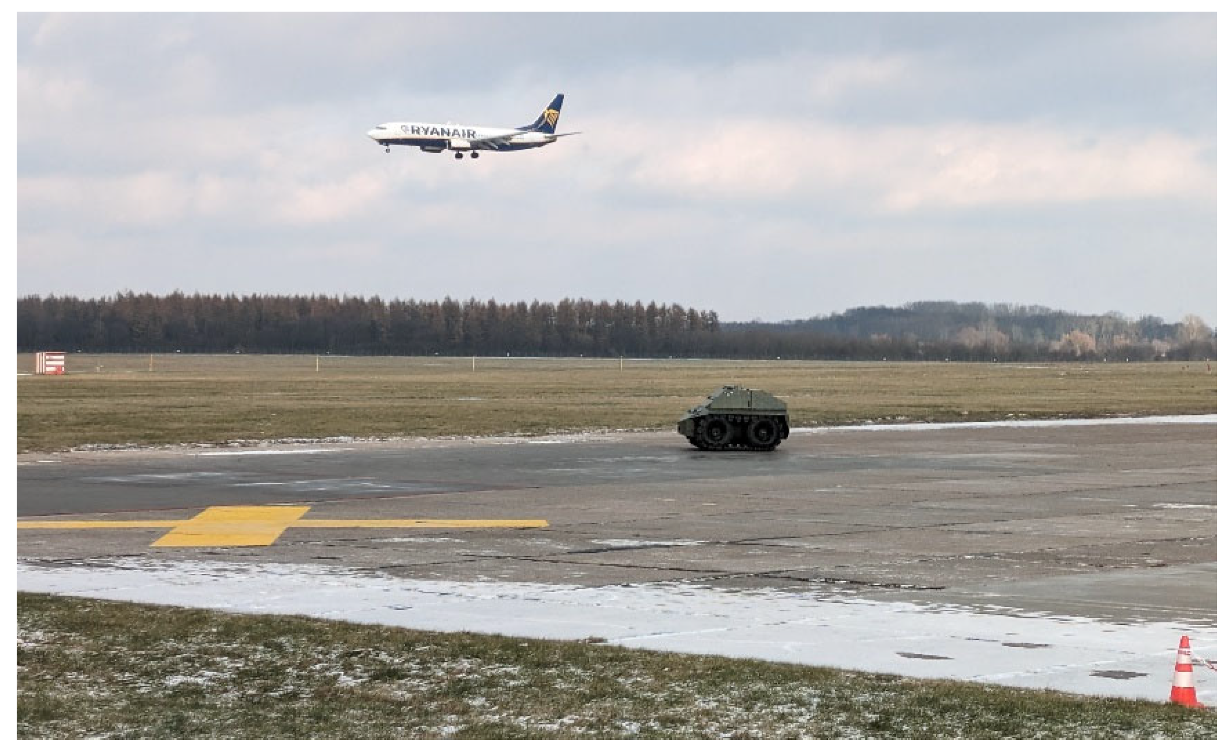
To demonstrate effectiveness and usefulness of proposed unmanned device in the context of trajectory tracking by autopilot and drives, as well as designed mechanics, the mobile robotic platform BIZON was tested in real working condition on the airport board.
Figure 10.
UGV BIZON on the airport board.
To check a correctness of the mechanics and control system of the device, a waypoint trajectory was applied on autopilot and tested considering two cases:
- a)
- typical PID-FF trajectory control,
- b)
- the PID-FF with tightening to the trajectory.
Realized trajectory was compared to simulation of the vehicle behavior considering model (11) – (12) and control law (13). The most important BIZON parameters are presented in Table 1. Included parameters are defined in chapter 3, which describes modelling and control technique.
Reference trajectory data was inserted to the autopilot as a waypoints. This way lines that connects inserted via points defines a trajectory. For the purpose, using the GNSS RTK module mounted in the robotic platform, determined its geographic coordinates. The coordinates are presented in Table 2.
Heading angle [0]
The data can be also stored in the Remote Control Station (RCS) to the moment, when the radio wireless connection works. Autopilot connecting with the RCS has implemented a special diagnostic algorithm to check the automatic control mode (full autonomy mode) performance. In critical situations, the algorithm may not allow to work in full automatic mode, then a check list of failures and inefficient elements is generated.
Before experiment, the trajectory coordinates was introduced to the platform device via special software package of RCS and visualized using Google Earth tool. Visualization is presented in Figure 11 a) and Figure 11 b).
Firstly, the simulations of the control system and waypoint trajectory realization was examined. For the tests purpose, the device model described in subsection 3.1 was considered. The device model was started from point no. 1 with assumed zero initial position and zero initial speed: and . At each waypoint the initials was zeroing whole the all tracking process.
Result of numerical simulations are presented in Figure 12.
Defined waypoint trajectory, shown in Figure 11, was realized by the mobile platform with desired cruise speed 5 km/h. The tightening function was also activated to compare with classic PID-FF control. Figure 13 shows trajectory performance by UGV when tightening function was deactivated.
Figure 14 shows realized waypoint trajectory by UGV with activated tightening function.
For better visualizing, realized cases can be compared and shown at one common picture. Figure 15 presents the two cases: PID-FF and PID-FF with activated tightening function. The difference is clearly visible.
The PID-FF-based control algorithm allows UGV to realize path designated by trajectory via points, also called waypoints. This way the course path consists of line sections that connects indicated waypoints. Hence, basing on the current platform position, the platform moves to the destination point (waypoint) with desired driving course obtained from heading angle computation. It means, that in results the platform does not realizes course by the line between waypoints, but only next to or along it. The situation is different when tightening function is activated. Then, having actual platform position and orientation i.e. distance between platform to path line, a course correction is computed and added to control. This way, the platform can move exactly along line section determined from two indicated waypoints.
Performed tests proved usefulness and effectiveness of implemented control and navigation algorithms in autopilot subsystem. Considering RTK correction in the navigation system GNSS RTK/INS, the accuracy of tracking in the context of geographic coordination did not exclude 0,1 m, but in case of relative position the accuracy was lower than 0,01 m. Neglecting the RTK correction, the autopilot system realized trajectory with accuracy about 0,4 m.
Additionally, performing the waypoint trajectory, i.e. platform mission, an effectiveness and correctness of software important elements were tested in the context of a failure of the measurement system. When the platform works in the tightening mode, a huge values of the heading angle may cause the platform stop and hide the measurement subsystem. To drop of the subsystem, a many conditions must be performed. One of them is the value of heading angle error or cruise error, XTE and finite time criteria related to performing trajectory.
4. Conclusions
Presented in this paper study of the performance of unmanned ground robotic device (in other UGV) shows performance of mechanical design. Numerical simulation of the chassis system and pavement measurement subsystem by three-dimensional finite element analysis confirms the strength and stiffness of the most important vehicle’s mechanical parts and shows the distribution of stress and deformation under the extremal condition.
The paper also presents an autopilot design based on Proportional-Integral-Derivative (PID) and Feed-Forward (FF) control. Presented tests of the control system shows and confirms that precise trajectory control works and gives a satisfactory quality.
Presented tests and measurements, prove that the mechanical design and control system works and performs the objective respecting the precise tracking, speed control and positioning. The control method due to the vehicle dynamics, seems to be promising method for airport or ground airstrip analyzing or testing pavement.
The future work can be related to implementing a new control system based on suboptimal techniques that increases autonomy of the vehicle related to our conception of the most autonomous UGV BIZON. After implementation the new control, we plan to test the vehicle behavior at the airport and compare its work due to actually implemented PID-FF control.
Author Contributions
methodology: Marcin Chodnicki and Paweł Pietruszewski; hardware and software: Marcin Chodnicki and Paweł Pietruszewski; validation: Mariusz Wesołowski and Sławomir Stępień; writing–original draft preparation: Sławomir Stępień; writing–review and editing: Mariusz Wesołowski and Sławomir Stępień; supervision: Mariusz Wesołowski, Mirosław Nowakowski and Sławomir Stępień. All authors have read and agreed to the published version of the manuscript.
Funding
This research was partially funded by the National Centre for Research and Development in Poland, project no.: POIR.01.01.01-00-0919/19.
Acknowledgments
The authors would like to thank Damian Dobrowolski (Dobrowolski LLC Company) for his support during the design of the mechanical system and the production of the device. We would like also to express our sincere appreciation to Damian for his valuable and constructive talks, suggestions and comments during writing and development of this research work.
Conflicts of Interest
The authors declare no conflict of interest.
References
- Singh S. The DARPA Urban Challenge: Autonomous Vehicles in City Traffic. Springer, 11 2009.
- Naranjo, J. E.; Clavijo, M.; Jimenez, F.; Gomez, O.; Rivera, J. L. and Anguita, M. Autonomous vehicle for surveillance missions in off-road environment. In Proceedings of IV IEEE Intelligent Vehicles Symposium, 2016, 98–103.
- Chang, J.-R.; Tseng, Y.-H.; Kang, S.-C.; Tseng, C.-H.; Wu, P.-H. The Study in Using an Autonomous Robot for Pavement Inspection. In Proceedings of the 24th International Symposium on Automation and Robotics in Construction, Kochi, India, 19–21 September 2007; 229–234.
- Tseng, Y.-H.; Kang, S.-C.; Chang, J.-R.; Lee, C.-H. Strategies for autonomous robots to inspect pavement distresses. Autom. Constr. 2011, 20, 1156–1172. [CrossRef]
- Pazderski D. Waypoint Following for Differentially Driven Wheeled Robots with Limited Velocity Perturbations. Asymptotic and Practical Stabilization Using Transverse Function Approach. Journal of Intelligent & Robotic Systems 2017, 85, 1-23. [CrossRef]
- Kurowski P.M., Engineering Analysis with SW Simulation Professional 2006. SDC Publishing 2006.
- Akin J. Ed, Finite Element Analysis Concepts via SolidWorks, World Scientific 2009.
- Dohrmann C.R., Key S.W., Heinstein M.W., Jung J., A least squares approach for uniform strain triangular and tetrahedral finite elements. International Journal for Numerical Methods in Engineering 1998, 42, 1181–1197.
- Puso M.A., Solberg J., A formulation and analysis of a stabilized nodally integrated tetrahedral. International Journal for Numerical Methods in Engineering 2006, 67, 841–867.
- Al-Milli, S., Seneviratne, L.D. and Althoefer, K. Track-terrain modelling and traversability prediction for tracked vehicles on soft terrain, Journal of Terramechanics 2010, 47, 151–160. [CrossRef]
- Liu, C., Chen, W.H. and Andrews, J., Optimisation based control framework for autonomous vehicles: algorithm and experiment, 2010 International Conference on Mechatronics and Automation (ICMA), August (2010, 1030–1035.
- Wong, J.Y., Theory of Ground Vehicles, John Wiley & Sons, New York, USA, 2008.
- Silva F. O. E. and Ferreira L. H. D. C., Design and implementation of a PID control system for a coaxial two-wheeled mobile robot, IEEE International Symposium on Industrial Electronics, Taipei, Taiwan 2013, 1-6.
- Khalaji A. K. and Moosavian S. A. A., Stabilization of a tractor-trailer wheeled robot, J. of Mechanical Science and Technology 2016, 30, 421-428.
- Buza, E., Omanovic, S., and Huseinovic, A., 2013. Pothole detection with image processing and spectral clustering. In Proceedings of the 2nd International Conference on Information Technology and Computer Networks (Vol. 810, p. 4853).
- Coenen, T. B., and Golroo, A., 2017. A review on automated pavement distress detection methods. Cogent Engineering, 4(1), 1374822. [CrossRef]
- Eriksson, J., Girod, L., Hull, B., Newton, R., Madden, S., and Balakrishnan, H., 2008. The pothole patrol: using a mobile sensor network for road surface monitoring. In Proceedings of the 6th international conference on Mobile systems, applications, and services (pp. 29-39). ACM.
- Zhang, Z., Ai, X., Chan, C. K., and Dahnoun, N., 2014. An efficient algorithm for pothole detection using stereo vision. In 2014 IEEE International Conference on Acoustics, Speech and Signal Processing (ICASSP) (pp. 564-568). IEEE.
- Yu, B. X., and Yu, X., 2006. Vibration-based system for pavement condition evaluation. In Applications of Advanced Technology in Transportation (pp. 183-189).
- Kim, T., and Ryu, S. K., 2014. Review and analysis of pothole detection methods. Journal of Emerging Trends in Computing and Information Sciences, 5(8), 603-608.
- Mei, A.; Zampetti, E.; Di Mascio, P.; Fontinovo, G.; Papa, P.; D’Andrea, A. ROADS—Rover for Bituminous Pavement Distress Survey: An Unmanned Ground Vehicle (UGV) Prototype for Pavement Distress Evaluation. Sensors 2022, 22, 3414. [CrossRef]
- Korayem, M.H., Nekoo, S.R. and Korayem, A.H. Finite time SDRE control design for mobile robots with differential wheels. J Mech Sci Technol 30, 4353–4361 (2016). [CrossRef]
- Nowakowski M. (2023). Perception technology for conversion of off-road vehicles for the purposes of unmanned missions. Journal of civil engineering and transport. 5(4), 15-27, ISSN 2658-1698, e-ISSN 2658-2120. [CrossRef]
- Dobrowolski LLC Company, www.dobrowolski.com.pl.
- Air Force Institute of Technology. https://itwl.pl.
Figure 1.
BIZON – unmanned ground platform view, (a) front view, (b) rear view.
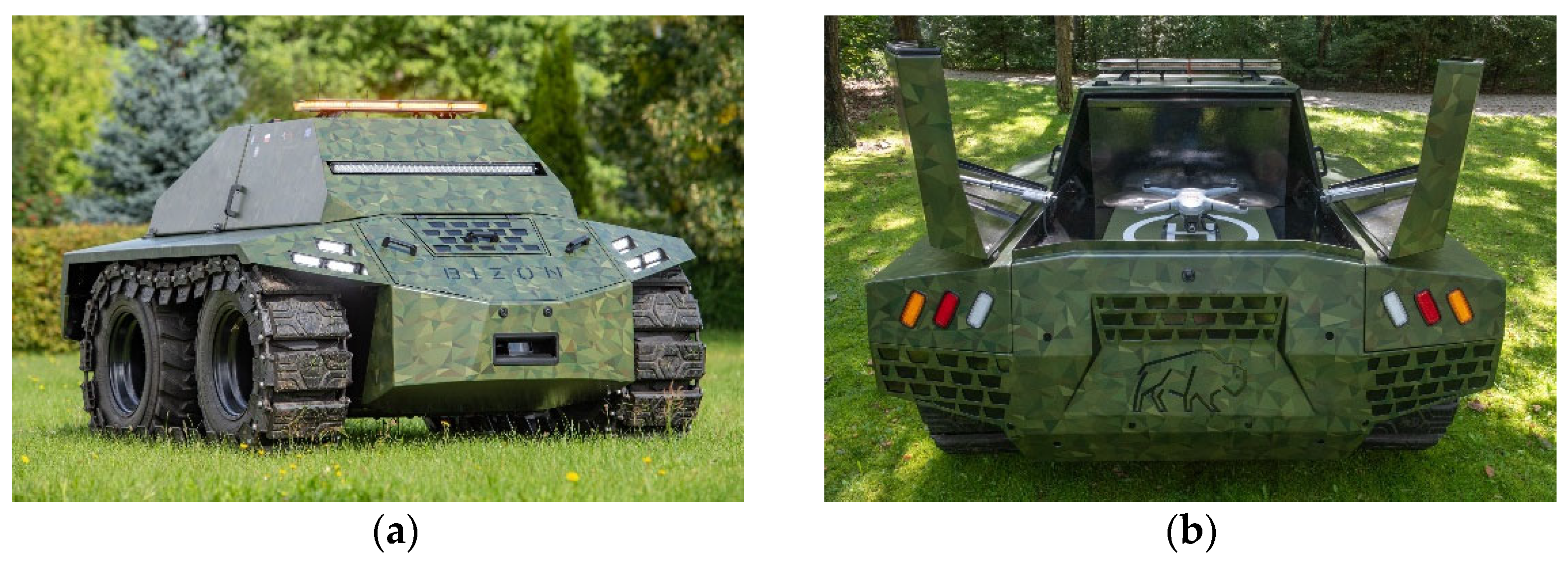
Figure 2.
Platform chassis geometry.
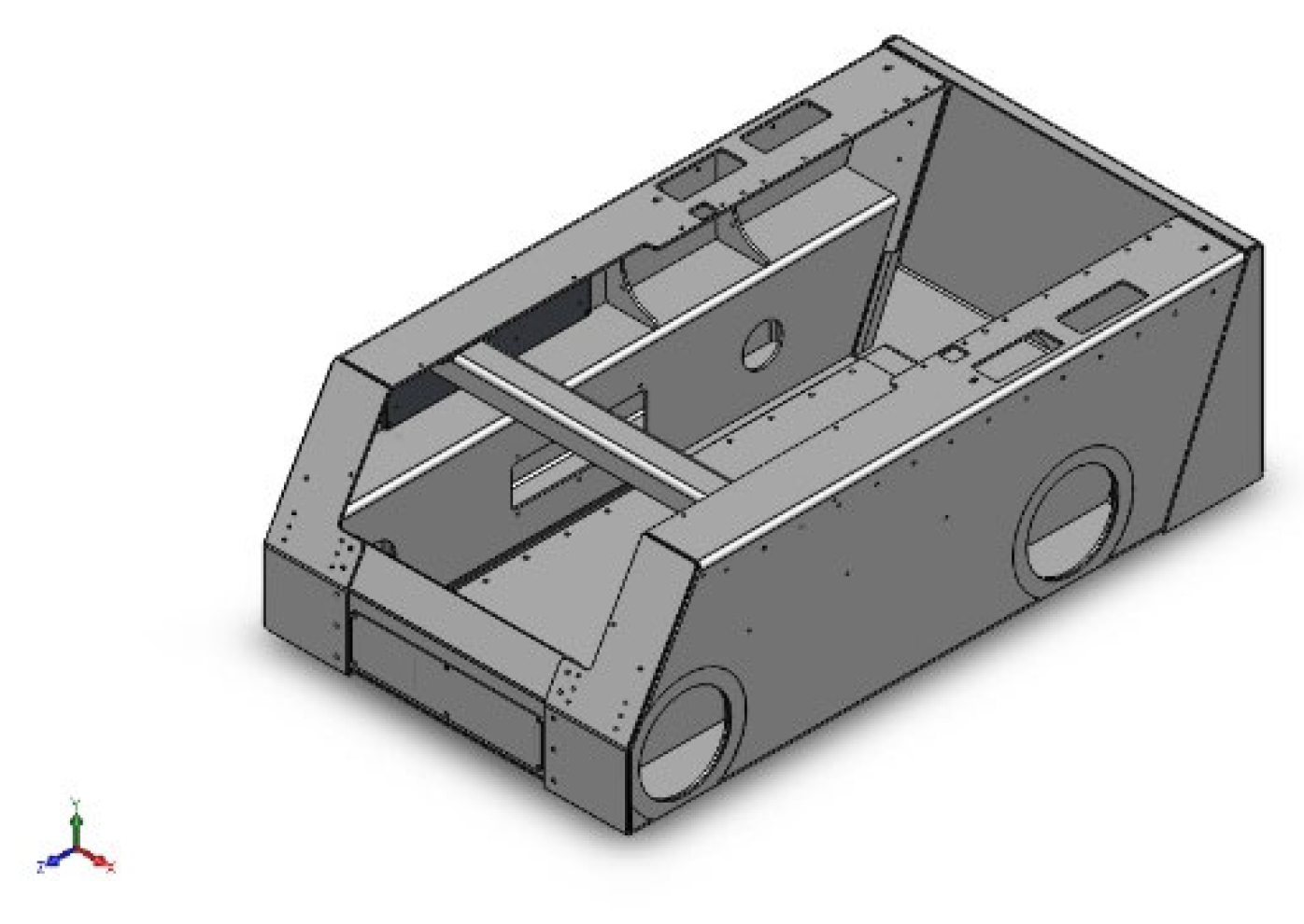
Figure 3.
Mesh of the chassis.
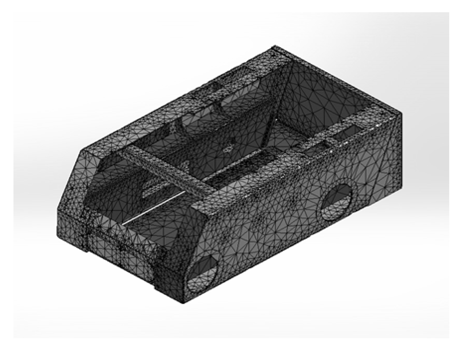
Figure 5.
Geometry of the measuring system.
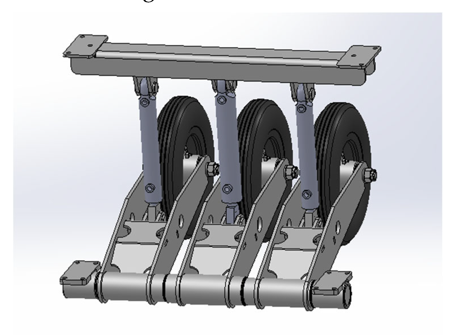
Figure 6.
Deformation results: a) actuators-beam, b) fork of wheel system.
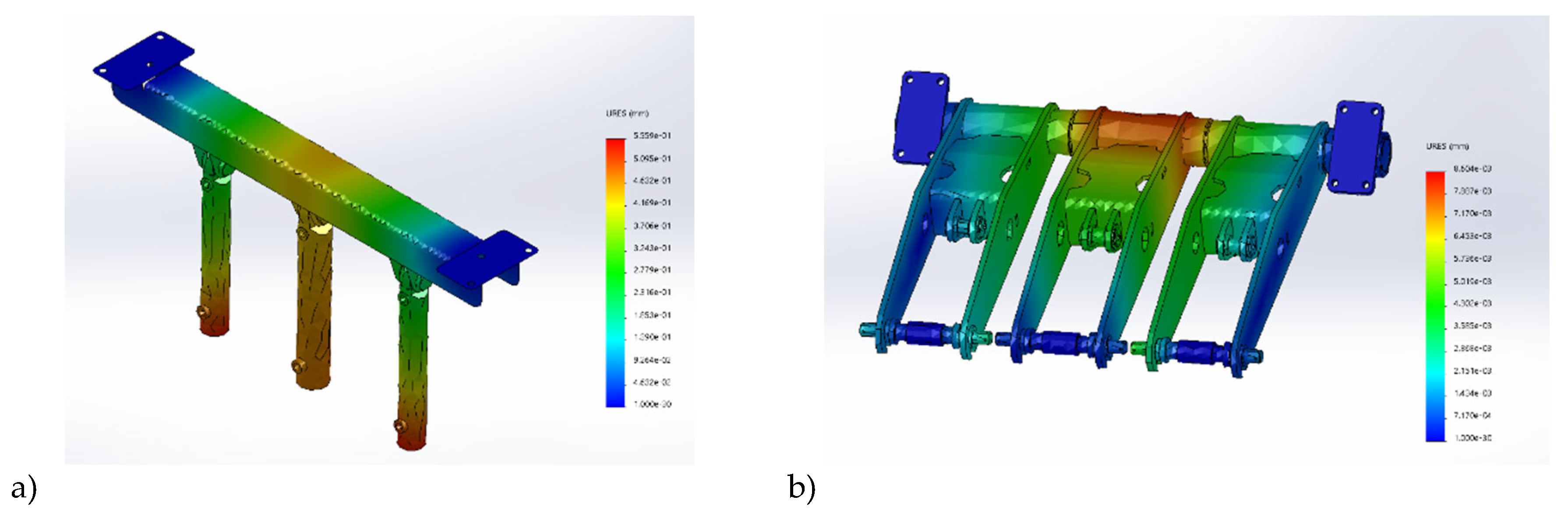
Figure 7.
Mobile platform model. Differential wheels approach
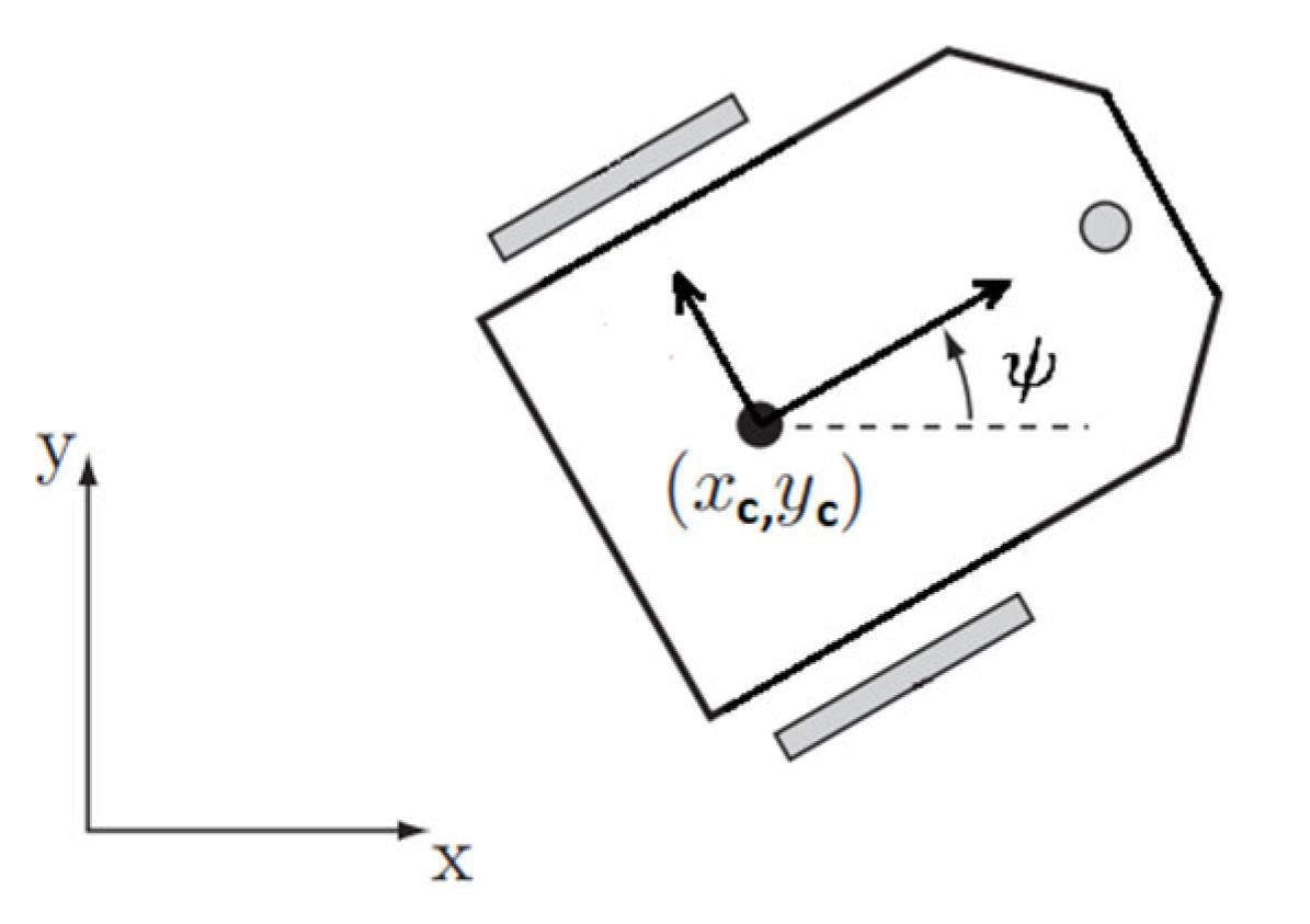
Figure 8.
The autopilot design.
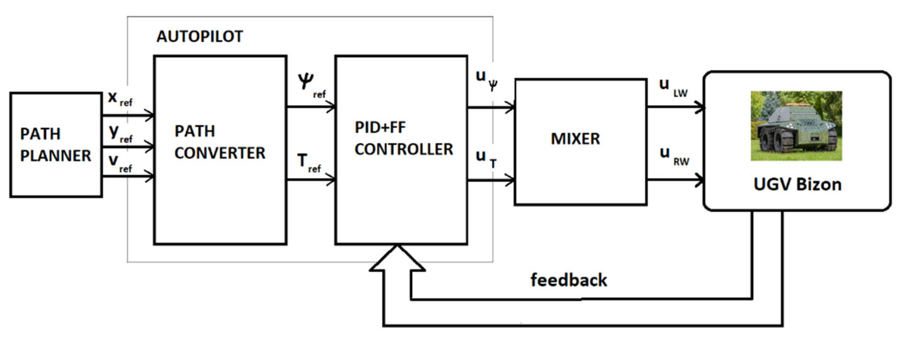
Figure 9.
The PID-FF controller.
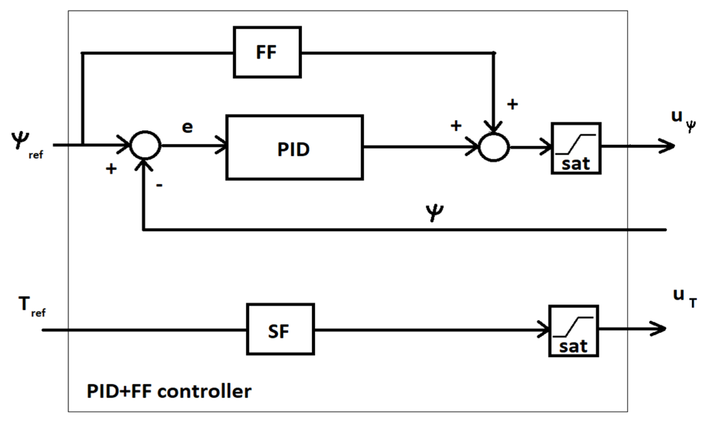
Figure 11.
Reference waypoint trajectory.
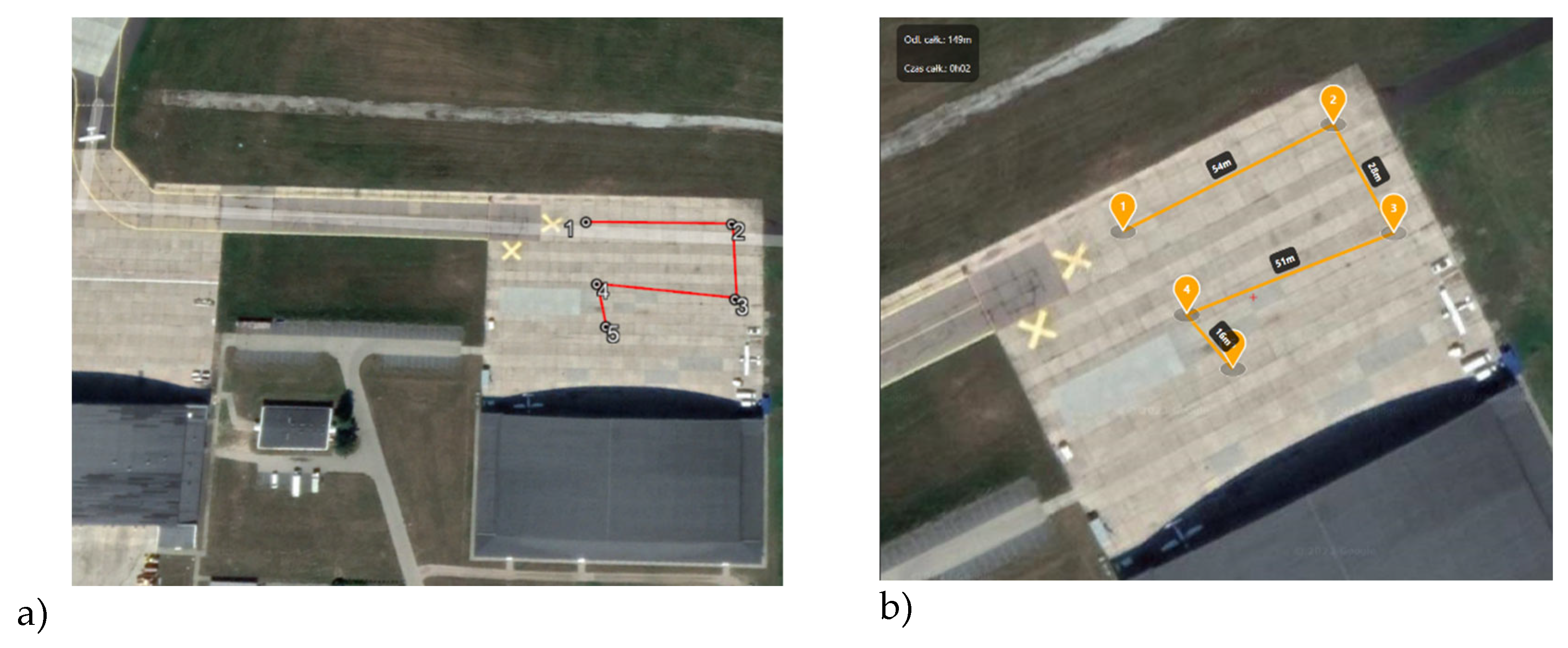
Figure 12.
Simulation result of performed trajectory.
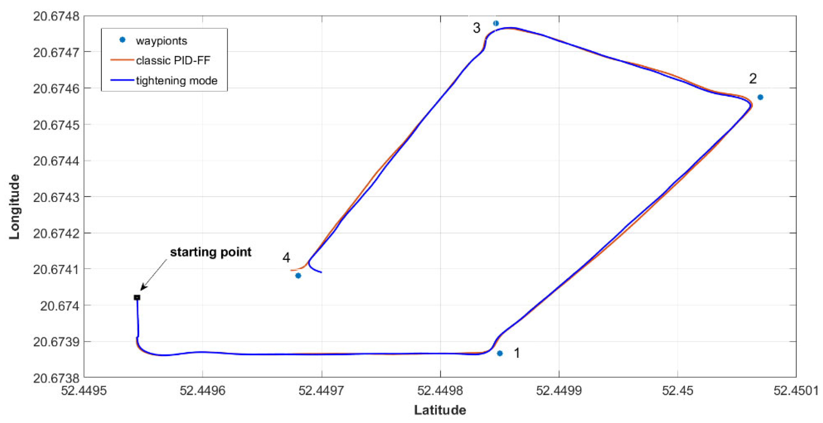
Figure 13.
UGV trajectory without tightening.
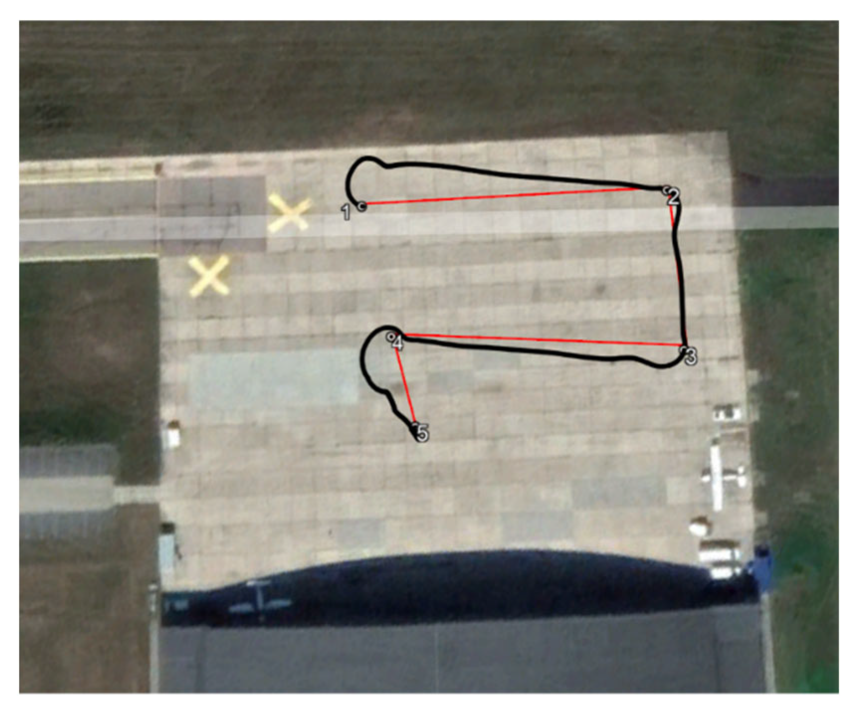
Figure 14.
UGV trajectory with tightening.
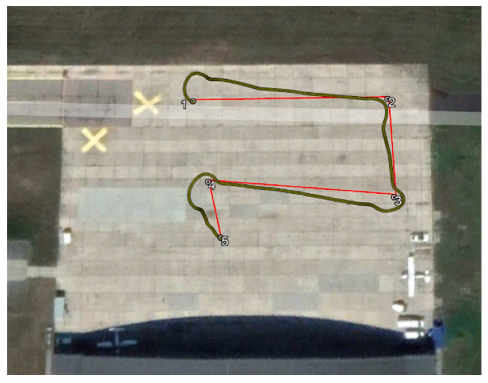
Figure 15.
Trajectories comparison.
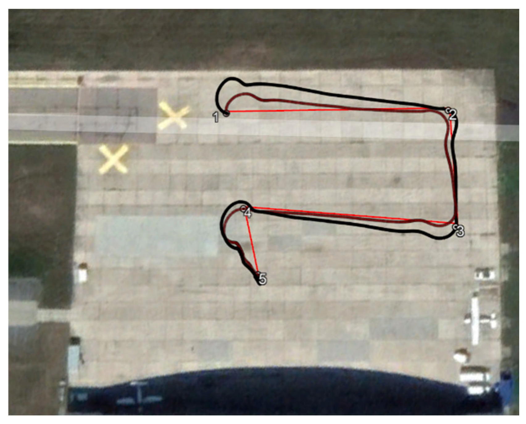

Table 1.
BIZON parameters.
| Parameter | Value [quantity] |
|---|---|
| 2000 [kg] | |
| 200 [kg] | |
| 0,6 [m] | |
| 0,5 [m] | |
| 21,2 [kg.m2] | |
| 0,02 [kg.m2] | |
| 0,27 [kg.m2] |
Table 2.
Trajectory coordinates.
| Point nr |
Geographic coordinates | Distance between via points [m] |
Heading angle [0] | |
|---|---|---|---|---|
| Latitude | Longitude | |||
| 1 | 52,44985032 | 20,67386627 | - | 63,2 |
| 2 | 52,45006937 | 20,67457438 | 54,4 | 151,0 |
| 3 | 52,44984705 | 20,67477822 | 28,6 | 248,6 |
| 4 | 52,44968031 | 20,67408085 | 51,0 | 140,7 |
| 5 | 52,44956840 | 20,67423340 | 16,5 | |
Disclaimer/Publisher’s Note: The statements, opinions and data contained in all publications are solely those of the individual author(s) and contributor(s) and not of MDPI and/or the editor(s). MDPI and/or the editor(s) disclaim responsibility for any injury to people or property resulting from any ideas, methods, instructions or products referred to in the content. |
© 2024 by the authors. Licensee MDPI, Basel, Switzerland. This article is an open access article distributed under the terms and conditions of the Creative Commons Attribution (CC BY) license (http://creativecommons.org/licenses/by/4.0/).
Copyright: This open access article is published under a Creative Commons CC BY 4.0 license, which permit the free download, distribution, and reuse, provided that the author and preprint are cited in any reuse.


