
Submitted:
06 February 2024
Posted:
08 February 2024
You are already at the latest version
Abstract
Since the introduction of Cross-laminated Timber (CLT) in Austria in the early 1990s, the adoption of this 90°-crosswise-laminated product has seen exponential growth worldwide. Compared to traditional laminated timber products (e.g. glulam), CLT provides improved dimensional stability, but with reduced out-of-plane bending stiffness. To improve the bending stiffness, while maintaining relative dimensional stability, a modified orientation of the inner layers in a diagonal direction can be used. This novel product is Diagonal-Cross-laminated Timber (DCLT), a composite timber product, consisting of inner layers which are rotated at different angle-ply orientations between 0 and 90 degrees to the outer layers. To properly model the out-of-plane bending behavior of the DCLT, analytical models and Finite Element Analysis (FEA) were used and the results were validated by third-point bending tests performed on DCLT panels with angle-ply orientations of 10°, 20°, 40°, 70°, and a conventional CLT 90° panel. The results indicate that DCLT panels with angle-ply cross-layers have a structural advantage in out-of-plane bending over traditional CLT (90°) panels. The development of DCLT and its introduction to the industry could enable the use of lower-quality timber that would not otherwise satisfy structural requirements for CLT.
Keywords:
Cross-laminated Timber (CLT)
; Grain orientation
; Hankinson’s formula
; Diagonal-Cross-laminated Timber (DCLT)
; Bending stiffness
1. Introduction
Wood, a natural orthotropic material, has unique properties in different grain directions of the three mutually perpendicular axes: longitudinal, radial, and tangential (as shown in Figure 1). The longitudinal axis L is parallel to the grain, the radial axis R is normal to the growth rings (perpendicular to the grain in the radial direction), and the tangential axis T is perpendicular to the grain but tangent to the growth rings. The strength and stiffness properties of wood in the grain direction are much higher than the strength and stiffness properties perpendicular to the grain direction. In addition to the mechanical properties, given its hygroscopic nature, wood dimensional changes (i.e., the shrinkage and swelling) occur in each direction and vary with Moisture Content (MC%). This property of wood is referred to as dimensional stability. The dimensional stability affects how a final timber product will distort in service. Percent shrinkage and swelling of wood are greatest in the tangential direction, less in the radial direction, and least in the longitudinal direction; the latter changes are mostly negligible.
The natural properties of wood have been the basis for innovations in mass timber products such as Glued-laminated Timber (GLT) and Cross-laminated Timber (CLT). GLT includes layers of timber boards glued together parallel in one major load-bearing direction (0°), CLT consists of crosswise orientated layers, where the layers are orientated perpendicular to each other, providing one major (0°), and one minor (90°) load-bearing direction for out-of-plane bending [1]. The cross layers of CLT help to minimize overall shrinkage and swelling of the structural panel. Thus, CLT panels show higher dimensional stability compared to GLT beams. For bending out-of-plane, CLT’s cross layers are responsible for the panel’s bidirectional strength and work to distribute the load in the minor direction as well. However, the cross layers have lower stiffness and strength (in the major axis direction), leading to a greater panel deflection than with GLT. Recognizing these relative advantages and limitations of GLT and CLT, an optimized/modified orientation of the inner layers in a diagonal direction could be developed to improve the out-of-plane bending stiffness while maintaining structural and dimensional stability.
The product created with inner layers at varying angles is called Diagonal-Cross-laminated Timber (DCLT). DCLT can be seen as a standard counterpart to CLT, offering improved mechanical properties using the same material properties and layer thicknesses. CLT is a balanced and symmetric laminate since the material properties, the thickness of its layers, and the orientation of its plies are symmetric about the midplane [2]. However, DCLT can be introduced as a balanced and antisymmetric laminate to improve the overall stiffness. This means that in DCLT panels; the plies with the same thickness are a mirror image of the geometrical midplane. Therefore, for each +α angle-ply laminate in the panel, there is an equally thick −α angle-ply laminate as well. Figure 2 illustrates the configurations of GLT, DCLT, and CLT to show how DCLT lay-up can be orientated compared to GLT and CLT products.
Several studies have been conducted to study the potential relationship between the grain orientation of DCLT’s inner lamina and the panel’s bending and shear stiffness properties. Buck et al. [4] investigated the difference between bending stiffness in conventional CLT panels and DCLT panels with inner layers of 45° grain orientation. They tested two groups of 20 five-layered panels, with orientations of 0°-90°-0°-90°-0° and 0°-45°-0°-45°-0° under third-point bending in the main load-carrying direction in a flatwise panel layup. Their evaluated results confirmed that the DCLT ± 45° bending strength and the apparent stiffness (EIapp) increased respectively by 35% and 15% over the conventional CLT panels with 90° layers. EIapp is defined as the apparent bending stiffness of the panel in the span direction including both bending and shear deformation while EIeff of the panel refers to the effective bending stiffness in the span direction.
Other researchers have shown interest in studying both the shear and bending performance of DCLT panels with different angle-ply orientations. Bahmanzad et al. [5] performed research on three-ply DCLT panels fabricated from eastern hemlock. The inner layer had grain orientations of 30°, 45°,60°, and CLT (90°) relative to the main load-bearing direction. Their results of the short-span three-point bending test, showed higher shear and bending properties for the DCLT 30° panels, followed by successively lower values for the DCLT 45°, 60°, and CLT (90°) panels. The EI app from their results showed an increase of 63%, 52%, and 38% respectively for DCLT 30°, DCLT 45°, and DCLT 60°, compared to CLT 90°.
Also, Arnold et al. [2] investigated the load-bearing behavior and efficiency of DCLT under bi-axial bending configuration experimentally and theoretically. They tested seven replicas of CLT and DCLT±30° and ±45° panels with different thicknesses. Their evaluation included an evaluation of the increase in torsional stiffness of DCLT panels compared to conventional CLT panels. They tested an applied parametric numerical model to evaluate the influence of the layer arrangement as well as the width and thickness of the laminations on the torsional stiffness. They also designed an analytical model for finding the torsional stiffness of the panels using two methods: the Kirchhoff-Love and Reissner-Mindlin equations. Their results showed a considerable increase in the torsional stiffness of DCLT panels compared to conventional Cross-laminated Timber panels. Their results confirmed that DCLT could improve biaxial bending stiffness. Therefore, it could be an alternative option to CLT for floor systems governed by serviceability limit states such as deflections or vibrations.
To determine wood properties at an angle to one of the principal axes, Hankinson’s criterion is the most common method. Over time researchers have proposed modifications to the base formula [6]; however, recent studies have confirmed the validity of fit to the experimental data for the original formula. For instance, Bahmanzad et al. [7] studied Hankinson’s formula to determine its effectiveness in predicting shear moduli and strength based on grain orientation. The shear stiffness and strength results from the short-span bending tests on three-ply CLT and DCLT panels appeared to fit the data fairly well. Another study regarding the impact of grain orientation on the mechanical properties of DCLT was done by Franzoni et al. [8]. They developed a 3D FEM DCLT model with four configurations having the same total thickness but different spans and the mid-layers of the panels orienting from 0° to 90° with an increment of 10°. Their findings confirmed that the failure load and the deflection are functions of grain orientation. Their results state that the effect on bending stiffness of rotating the grain orientation becomes more significant for DCLT panels with shorter span-to-depth ratios.
In this study, three approaches were used: a theoretical approach, experimental testing, and FEM modeling. For this work, 12 four-ply DCLT ±α panels and one four-ply CLT panel were fabricated from a local hardwood species, black locust (Robinia pseudoacacia), for the parallel (0°) top and bottom layers, and a local softwood species, eastern white pine (Pinus strobus), was used for the two diagonal (±α°) inner-layers. Before the experiment, an analytical model was developed using Hankinson’s criterion with the Shear Analogy approach to predict the bending performance of each set of DCLT panels. The Shear Analogy method proposed by Kreuzinger [9], and used in the US CLT Handbook [10], gives the composite bending and shear stiffness (EIeff, GAeff, EIapp) of the CLT panels using the values of the elastic and shear moduli parallel and perpendicular to the grain (E0, E90, G90) of the species in each layer [11]. The bending stiffness properties of the DCLT and CLT panels from this theory were then compared to the experimental results from the third-point bending test. The finite element analysis also simulated the third-point bending test and the results were compared with the results of the Shear Analogy method and experimental tests. This study provides methods of predicting the bending stiffness of DCLT and CLT panels with available or measured elastic modulus parallel to the grain of the species used in the panel fabrication. These methods of prediction could help utilize and introduce non-standard species for the fabrication of these products.
2. Materials and Methodology
2.1. Theoretical Investigations
Initial investigations were done on predicting the bending stiffness of DCLT panels with different grain orientation angles and species. An analytical model was developed by applying Hankinson’s formula in the Shear Analogy approach. Hankinson’s formula (Equation 1 and Equation 2) was used to find the axial and shear stiffness values of the angle-ply inner layers, and the final panel stiffness (EIapp) was found using the Shear Analogy approach (Equation 3, 4, and 5),
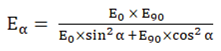
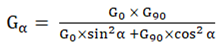 where, α is the angle of the grain orientation off the main axis, Eα is Modulus of Elasticity in the major strength direction of the diagonal layer, E0 and E90 are Modulus of Elasticity parallel and perpendicular to the grain. Gα is shear modulus of the diagonal layer in the span direction G0, and G90 are shear moduli parallel and perpendicular to the grain,
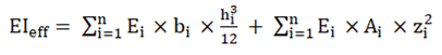 where, i is the individual layer of the panel, EIeff is the effective bending stiffness in the span direction, Ei is the Modulus of Elasticity of individual layer that can be E0 for outer layers and Eα for inner layers, bi is the width of the effective cross-section, hi is the height of the individual layer, Ai is the area of the effective cross-section and zi is the distance of the neutral axis of the individual layer from the neutral axis of the panel,
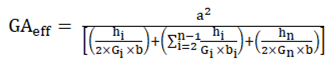 where, GAeff is the effective shear stiffness in the span direction, a is the distance between the neutral axis of the outer layers, bi is the width of the effective cross-section, hi is the height of the individual layer and Gi is the shear modulus of the individual layer that can be G0 for outer layers and Gα for inner layers,
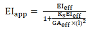 where, EIapp is the apparent bending stiffness in the span direction including both bending and shear deformation, EIeff is the effective bending stiffness in the span direction using the shear analogy method, GAeff is the effective shear stiffness in the span direction using the shear analogy method, Ks is a factor based on the ratio of deflection due to bending to deflection due to shear (12.96 for third-point loading) and l is the length of the span.
2.2. DCLT Panel Preparation
A total of 1.8 m3 (750-board feet) of ungraded, rough-sawn, random width 31-mm thickness, 3-m length black locust boards were purchased from a sawmill in Newfield, NY. Also, a total of 24 NeLMA [12] finish grade, flat-sawn eastern white pine boards with 22-mm thickness, 197-mm width, and 3.65-m length, were purchased from a local lumber yard near Syracuse, NY. The eastern white pine boards had been kiln-dried and surfaced four sides (S4S), but the black locust boards needed to be conditioned and surfaced (S4S) before fabrication. All the boards were then placed in an ambient temperature laboratory room to reach an equilibrium moisture content of approximately 12%. The average moisture content of the boards, determined with a Delmhorst (BD 2100) pin-type moisture meter, was measured as 11.8% at the time of fabricating the specimens. They were surfaced and planed to the desired thickness of 19 mm. Three replicates of each four-ply DCLT (± 10°, ± 20°, ± 40°, and 70°) and one four-ply CLT (DCLT 90°) panel were fabricated to final dimensions of 76 mm thick, 30 cm wide, and 2.74-m long. Figure 3 illustrates the dimensions and the orientation of the panels. The width-to-thickness ratio of all the diagonal DCLT panels in this study followed the standard recommendations of 4:1 to limit the impact of rolling shear [13]. The white pine boards (angle plies) were cut to the desired size from straight grain and defect-free sections, eliminating the possible effects of knots on the results. However, because of the NeLMA finish grade’s small knots and the difficult process of cutting the boards in different grain orientations, as shown in Figure 4a, minimal numbers of small knots were included in some of the boards. Before panel assembly, the longitudinal Modulus of Elasticity (MoE) of each black locust board (individual outer layer) and three eastern white pine sample boards was measured using the flatwise measured deflection of a simply supported board under a non-destructive center-point loading.
For panel fabrication the boards were face-glued using Loctite HB X452 Purbond (Henkel Corporation, Bridgewater, NJ) polyurethane adhesive with a recommended spread rate of 180 g/m2 was used to glue the top and bottom of the lamina (face-glued), and without attention to the position of the board defects. The grain orientations of boards used in the inner layers were alternated in the second and third layers (Figure 3). The DCLT panels and the CLT panel clamping pressure was controlled- by calibrated tightening torque to attain a minimum pressure of 410 kPa for 24 hours, using a mechanical press [14]. Figure 4b, c, and d shows the panels’ preparation process.
2.3. Third-point Bending Test
Third-point load tests as outlined in ASTM D 198 [15] were performed on the panels using a Young Universal Testing Machine outfitted with a 445 kN load cell and two linear variable differential transducers (LVDT). One LVDT was connected to the Young testing machine to measure the local displacement of load heads over a 0–150 mm range and the other one was installed on the top center of the panel to measure the displacement of top center of the panel relative to the load heads over a 0-75 mm. The deflections from both LVDTs and loading data were recorded with LabView® Software [16] on a dedicated personal computer. The total deflection was the sum of the two recorded deflections from LVDTs. The experimental setup is illustrated schematically in Figure 5 with the actual test set-up shown in Figure 6.
The corresponding bending stiffness value from this test setup was acquired from Equation 6:
 where, Eapp is apparent bending stiffness, P/Δ is the slope of the linear range of the load-deformation curve below the proportional limit with P and Δ accordingly being the maximum load and deflection at the proportional limit, l is the span length, b and h are the width and the thickness of the specimen.
2.4. Finite Element Method
In order to further understand the bending performance of DCLT panels and the experimental results of the third-point test on the specimens, a numerical finite element (FE) model was developed using the research version of ANSYS Workbench 2022 [17] finite element software. The panels were modeled using two different linear elastic orthotropic element types, one for black locust in the top and bottom layers, and one for eastern white pine in the cross layers.
Nine independent elastic constants are required to define the mechanical response of an orthotropic material in the simulation. These constants are three elastic moduli (E), three Poisson’s ratios (ν), and three shear moduli (G). For the material property values input in the simulations, the longitudinal elastic moduli values (EL) for black locust and eastern white pine were obtained from the USDA Wood Handbook [17]. There are no available published values for the ratio of ET/EL, ER/EL, GTR/EL, GLR/EL, GTR/EL, and the Poisson’s ratios for the species used in this study.
The USDA Wood Handbook [18] provides elastic ratios with respect to the longitudinal elastic modulus for some softwood and hardwood species. However, there are no available published values or elastic ratios for the constants of ER, GTL, and ET and the three required Poisson’s ratios for eastern white pine. To predict these elastic constants using the available longitudinal (parallel to the grain) modulus of elasticity value, linear regressions (confidence level of 95%) were performed on each constant of the species in the USDA Wood Handbook [18] with available elastic ratios, regarding the longitudinal MoE as the predictor using Microsoft Excel [19]. The regressions showed R-squares ranging from 80% to 99% and a P-value less than the significance level (0.05) indicating a validation for prediction with a statistically significant correlation between MoE and the response elastic constant.
The found ratios were repeated for another set of modeling considering the measured longitudinal MoE (from a simply supported bending test prior to panel fabrication) of black locust and eastern white pine boards as the longitudinal modulus of elasticity values. The final elastic constants for materials in FEM simulations are reported in Table 1.
FEM ANSYS Workbench [17] simulations were performed under the “Static Structural” analysis system on one model of each DCLT ± 10°, DCLT ± 20°, DCLT ± 40°, DCLT ± 70°, and CLT specimens. The panels were modeled with the specifications for material, loading, and boundary conditions identical to the third-point bending test to assure the accuracy of the comparison and validation. Mesh refinement was also performed under mechanical physics preference (program-controlled element order) by subdividing the mesh size to the rectangular elements with the size of 7 mm for each solid geometry. The mesh elements used for the sample specimens were higher order elements: SOLID186 element: 3-D 20 nodes, TARGE170 3-D target surface for the associated contact element of CONTA174: 3-D 8 nodes surface-to-surface, and SURF154: 3D structural surface effect. Table 2 shows the details of the mesh sizing and the refinement quality of the model.
For each set of simulations, three coordinate systems were defined regarding the parallel (0°, global coordinate system) and two diagonal layers with ±α° rotation of the main axis direction (x-y). The simulation’s details and the details of different coordinate systems designed in the modeling are shown in Figure 7. After each simulation, load-deflection data was recorded to calculate the bending stiffness of each sample using Equation 6.
3. Results and Discussion
3.1. Hankinson’s Theory Results
To evaluate the bending stiffness of the DCLT panels, the apparent bending stiffness has been calculated using the Shear Analogy approach. As mentioned in the methodology section, Hankinson’s equation has been used in the Shear Analogy approach to provide the stiffness properties of the angled inner layers of the panels.
3.2. Third-point Bending Test Results
As shown in Figure 8, the slope of the load-deflection curves decreases while the angle-ply orientation increases toward 90° or CLT. Therefore, the grain orientation of the inner layers is confirmed to affect the stiffness of the panels. Regarding the data from the testing (Table 4), the apparent bending stiffness of the panels is improved by 33% from CLT to DCLT±10°. This indicates that grain orientation had a statistically significant effect on the apparent bending stiffness of the DCLT panels. Table 5 also summarizes the difference percentages (%) between the bending stiffness properties of DCLT panels with different grain orientations in inner layers.
3.3. Finite Element Analysis
After each DCLT±α sample was tested under the simulations, the deflection results from the third-point bending loading were recorded.
The simulations were repeated one more time with the material properties of black locust and eastern white pine being considered with the measured MoE value instead of the published handbook values. As results show, the simulated DCLT samples with measured MoE have approximately 12-14% higher apparent bending stiffness than the results using published EL.
Regarding the data presented in Table 5, FEM validates the experimental and theoretical results indicating that decreasing the angle of grain orientation in the inner layers of the panels increases the bending stiffness. The Finite Element Method data show that DCLT±10° has an improved apparent bending stiffness by approximately 35% (compared to 90° lay-up) when using either the USDA Wood Handbook [18] values or measured MoE of the outer layers as input for simulated models. Table 8 summarizes the percent difference (%) between the bending stiffness properties of DCLT panels with different grain orientations in inner layers.
3.4. DCLT’s Bending Stiffness Comparison Between the Methods
Considering all the assessed methods in the study, Figure 10 shows the final apparent bending stiffness results of each method for comparison. As the plots indicate, the highest values for all the grain orientations of DCLT panels and the CLT panel are from the results of FEM modeling using the measured MoE of the boards. This FEM result is very similar to the experimental results from third-point bending tests. An obvious observation is that using the measured MoE of the layers provides more accurate models than using the reference MoE from the Wood Handbook. The results from the theory (Hankinson’s formula in Shear Analogy) under-predict the actual bending stiffness The results from these experiments show approximately 50% higher values of apparent bending stiffness compared to the theoretical values from the Hankinson/Shear Analogy approach with published the USDA Wood Handbook’s reference values.
4. Conclusion
This study investigated the bending stiffness of four-ply Diagonal-Cross-laminated Timber (DCLT) panels consisting of five different grain orientations of 90° (CLT), 70°, 40°, 20°, and 10° in the cross-layers. According to the third-point bending tests, the DCLT±10° panels were the stiffest followed successively by the DCLT±20°, ±40°, ±70°, and 90° (CLT) panels. These results support the modeled results acquired from Hankinson’s input in Shear Analogy and FEM simulations. The results from the three methods agreed that the decrease in the angle of the inner layer grain reorientation would improve the bending stiffness properties of CLT panels. The apparent bending stiffness from DCLT 90° to DCLT±10° has an increase of 33%, 24%, and 35% respectively regarding the assessed methods of experimental, theoretical, and FEM modeling. This study indicates that DCLT panels with angle-ply cross-layers have a structural advantage over traditional CLT (90°) panels. Using these panels would allow increased spans or load-carrying capacity for a given panel span-to-depth ratio. The development of DCLT and its introduction to the industry could also enable the utilization of lower-quality timber that would not otherwise satisfy structural requirements for CLT. DCLT opens new possibilities for efficient material usage in massive timber construction. Additionally, this study validates methods of predicting the bending stiffness of DCLT and CLT panels with available or measured elastic modulus parallel to the grain of the species used in the panel fabrication. This method of prediction could help utilize and introduce non-standard species for the fabrication of these products.
Acknowledgments
This research was generously supported by a USDA Wood Innovation Grant; grant number: 20-DG-11094200-179.
References
- Bejtka, Cross (CLT) and diagonal (DLT) laminated timber as innovative material for beam elements, Karlsruher Institut für Technologie (KIT) Scientific Publishing, 2011.
- M. Arnold, P. Dietsch, R. Maderebner, S. Winter, Diagonal laminated timber—Experimental, analytical, and numerical studies on the torsional stiffness, Construction and Building Materials. 322 (2022) 126455. [CrossRef]
- S. Kurzinski, P. Crovella, W. Smith, Evaluating the Effect of Inner Layer Grain Orientation on Dimensional Stability in Hybrid Species Cross-and Diagonal-Cross-laminated Timber (DCLT), Mass Timber Construction Journal, 6 (2023) 11-16.
- D. Buck, X.A. Wang, O. Hagman, A. Gustafsson, Bending properties of Cross Laminated Timber (CLT) with a 45° alternating layer configuration, BioResources. 11 (2016) 4633–4644. [CrossRef]
- Bahmanzad, P.L. Clouston, S.R. Arwade, A.C. Schreyer, Shear Properties of Symmetric Angle-Ply Cross-Laminated Timber Panels, Journal of Materials in Civil Engineering. 32 (2020) 04020254. [CrossRef]
- M. Yoshito, K. Hiroe, T. Yukari, N. Yasue, Relationship between the Strength and Grain Orientation of Wood: Examination and modification of the Hankinson’s Formula, The University of Tokyo Graduate School of Agriculture and Life Sciences Exercise Forest. 93 (1995) 1–5.
- Bahmanzad, P.L. Clouston, S.R. Arwade, A.C. Schreyer, Shear Properties of Eastern Hemlock with Respect to Fiber Orientation for Use in Cross Laminated Timber, Journal of Materials in Civil Engineering. 32 (2020) 04020165. [CrossRef]
- L. Franzoni, A. Lebée, F. Lyon, G. Foret, Influence of orientation and number of layers on the elastic response and failure modes on CLT floors: modeling and parameter studies, European Journal of Wood and Wood Products. 74 (2016) 671–684. [CrossRef]
- H. Kreuzinger, Platten, Scheiben und Schalen, Bauen Mit Holz. 101 (1999) 34–39.
- E. Karacebeyli, B. Douglas, CLT Handbook - US Edition, FPInnovations and Binational Softwood Lumber Council, Point-Claire, Quebec, 2013.
- S. Kurzinski, P.L. Crovella, Predicting the Strength and Serviceability Performance of Cross-Laminated Timber (CLT) Panels Fabricated with High-Density Hardwood, WCTE 2021, Santiago, Chile, 2021.
- American Lumber Standard Committee (ALSC), Northeastern Lumber Manufacturers Association, Standard Grading Rules for Northeastern Lumber, Northeastern Lumber Manufacturers Association, Maine, USA., 2021.
- American National Standard Institute, ANSI-APA/PRG 320 - Standard for Performance-Rated Cross-Laminated Timber, APA – The Engineered Wood Association, New York, NY, 2019.
- R.S. Shoberg, Engineering Fundamentals of Threaded Fastener Design and Analysis, RS Technologies. (2000) 1–39. Available online: http://www.hexagon.de/rs/engineering fundamentals.pdf.
- American Society for Testing and Materials Committee, ASTM D198- 15, (2015).
- National Instruments Corporation, LabVIEW, Austin, Texas, USA. (2021).
- ANSYS Inc, ANSYS® Workbench, Canonsburg, Pennsylvania, USA. (2022).
- Forest Products Laboratory, USDA Wood handbook—Wood as an engineering material. General Technical Report FPL-GTR-190., Madison, WI: U.S, 2021. [CrossRef]
- Microsoft Corporation., Microsoft Excel, Redmond, Washington, USA. (2021).
Figure 1.
Three Perpendicular Axes of Wood Grain Orientation.
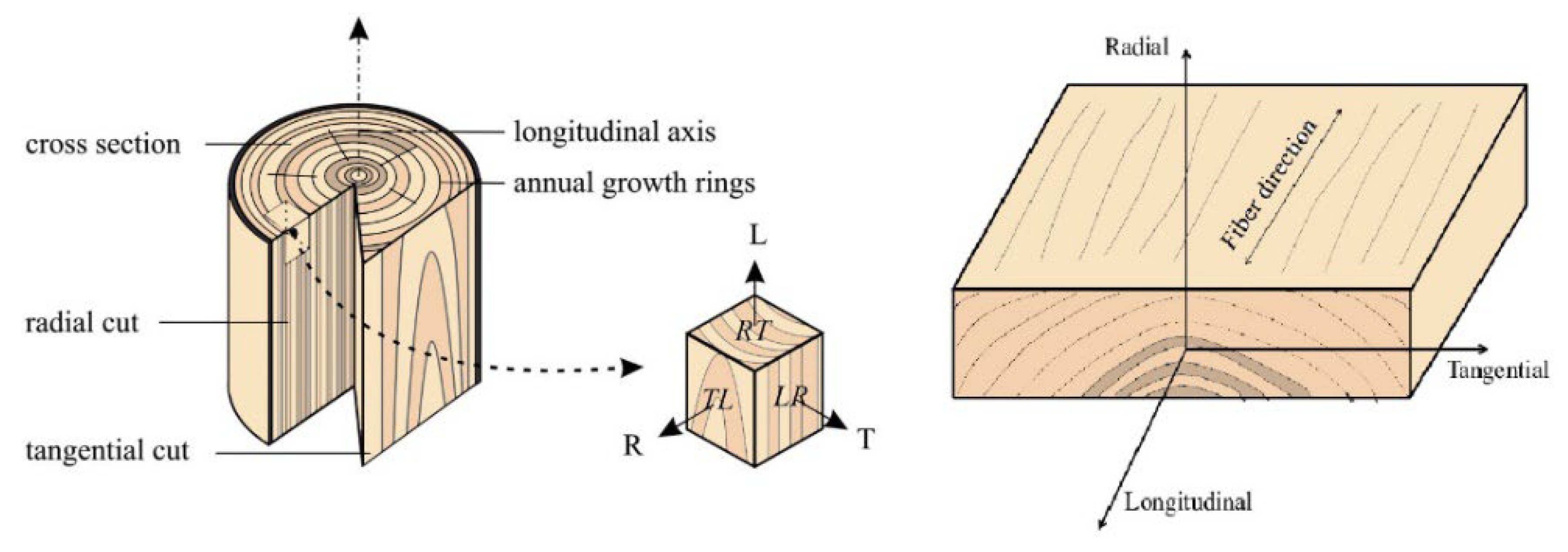
Figure 2.
GLT, DCLT, and CLT Lay-up Configurations [3].
Figure 2.
GLT, DCLT, and CLT Lay-up Configurations [3].
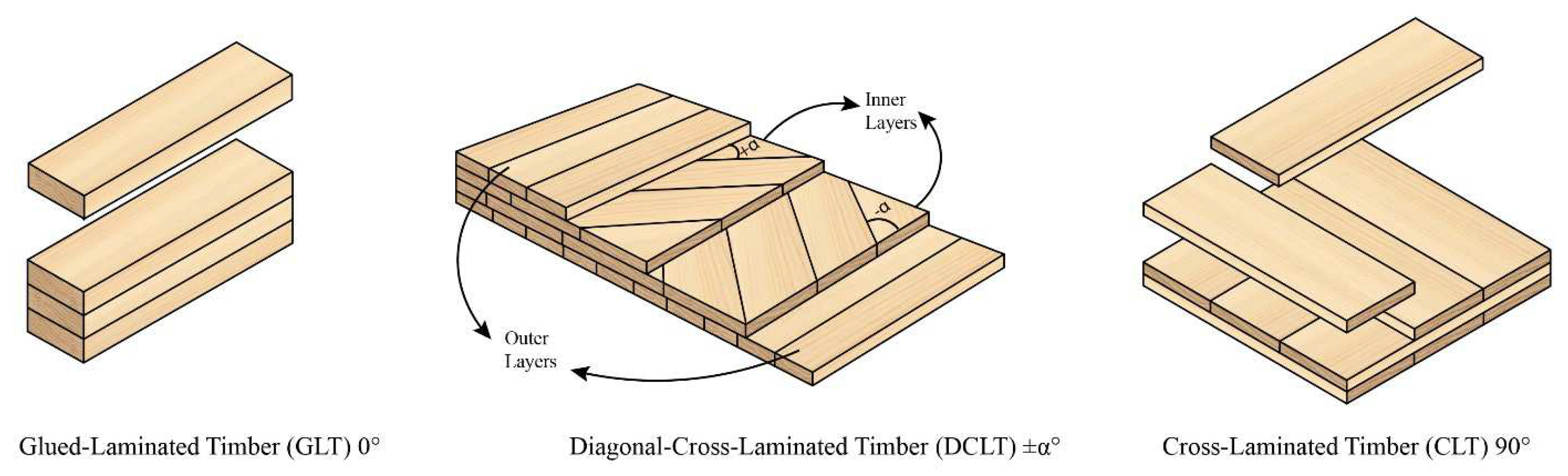
Figure 3.
Dimensions and Orientations of DCLT Panels of the Study.
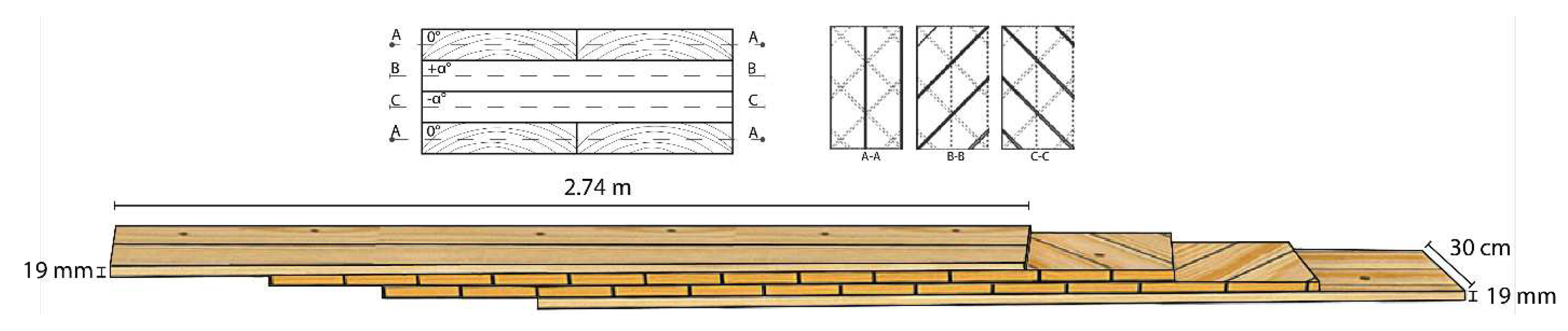
Figure 4.
From Left, a) Cutting of the Boards to Desired Grain Orientation (representative sample at 10°), b) and c) DCLT Panel’s Gluing Process, and d) DCLT Panel’s Pressing Process.
Figure 4.
From Left, a) Cutting of the Boards to Desired Grain Orientation (representative sample at 10°), b) and c) DCLT Panel’s Gluing Process, and d) DCLT Panel’s Pressing Process.
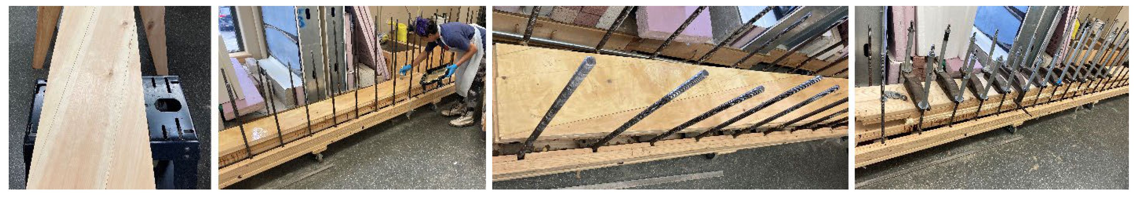
Figure 5.
Schematic Representation of Testing Arrangement and LVDTs’ Locations for DCLT Bending Specimens.
Figure 5.
Schematic Representation of Testing Arrangement and LVDTs’ Locations for DCLT Bending Specimens.
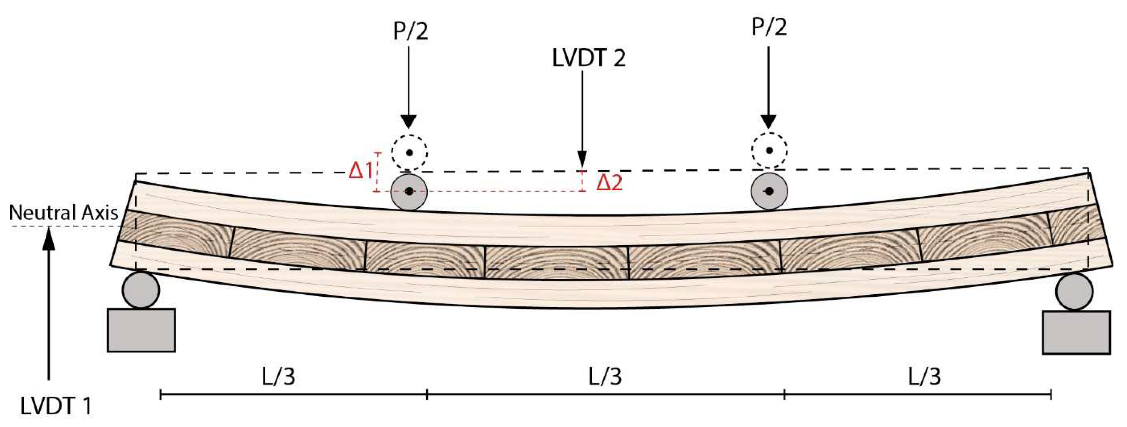
Figure 6.
Actual Testing Arrangement for DCLT Bending Specimens.
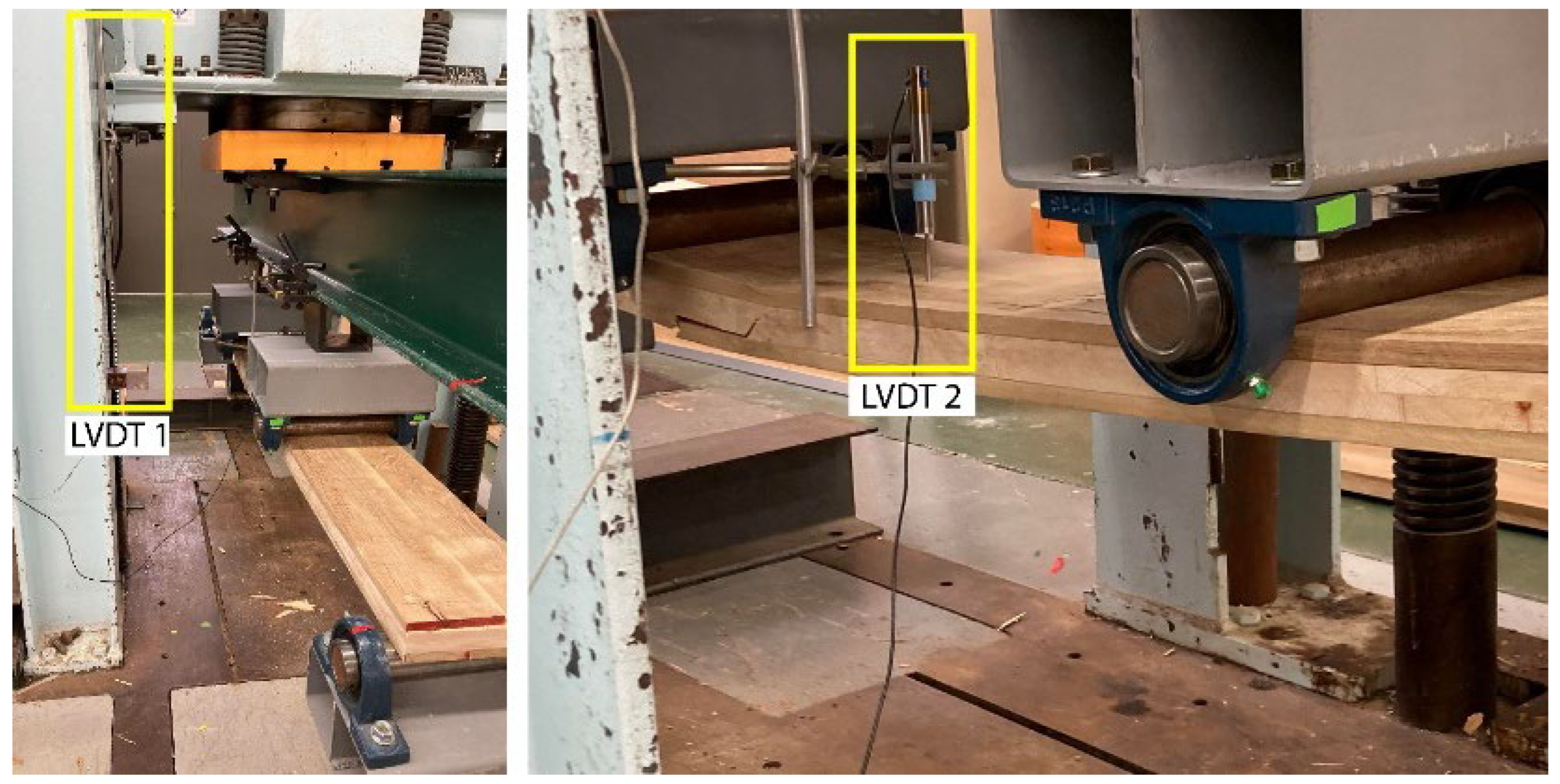
Figure 7.
Representative Samples of the Finite Element Meshing and Modeling Showing Details of Relative Mesh Size and Coordinate Systems.
Figure 7.
Representative Samples of the Finite Element Meshing and Modeling Showing Details of Relative Mesh Size and Coordinate Systems.
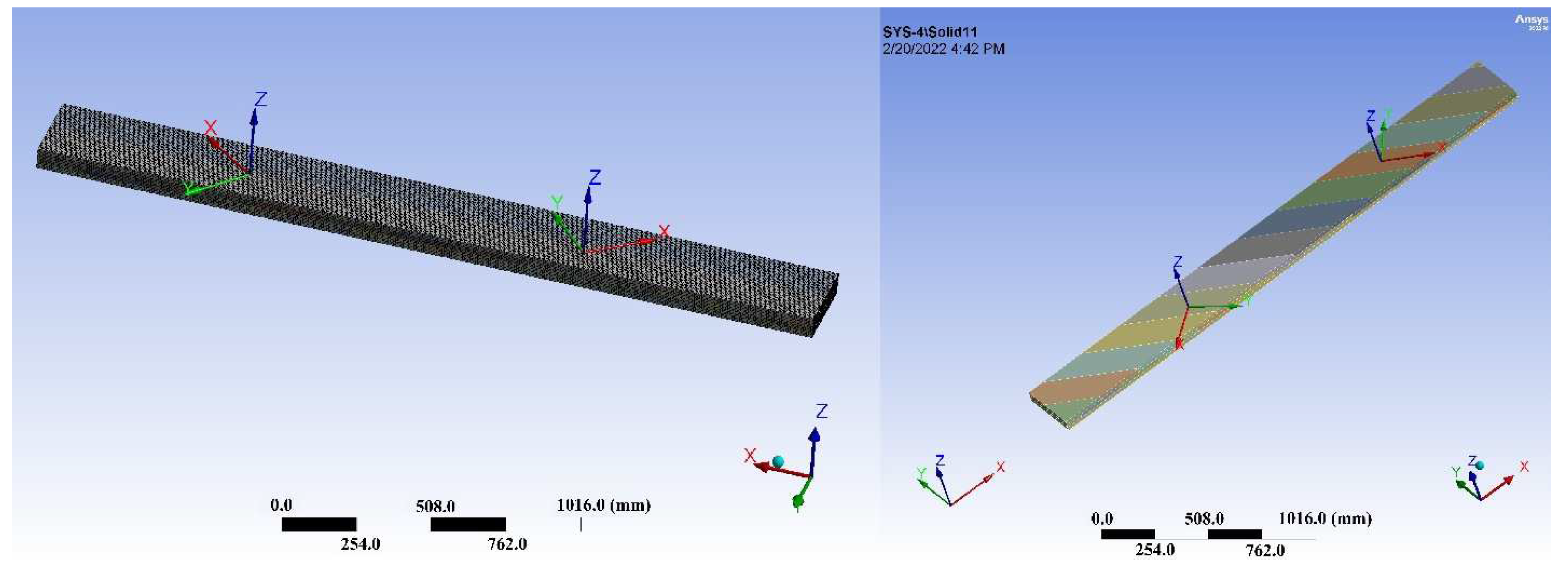
Figure 8.
Load-Deflection Curves of DCLT±α Representative Samples Tested Under Third-Point Bending Tests, Full Tests Result.
Figure 8.
Load-Deflection Curves of DCLT±α Representative Samples Tested Under Third-Point Bending Tests, Full Tests Result.
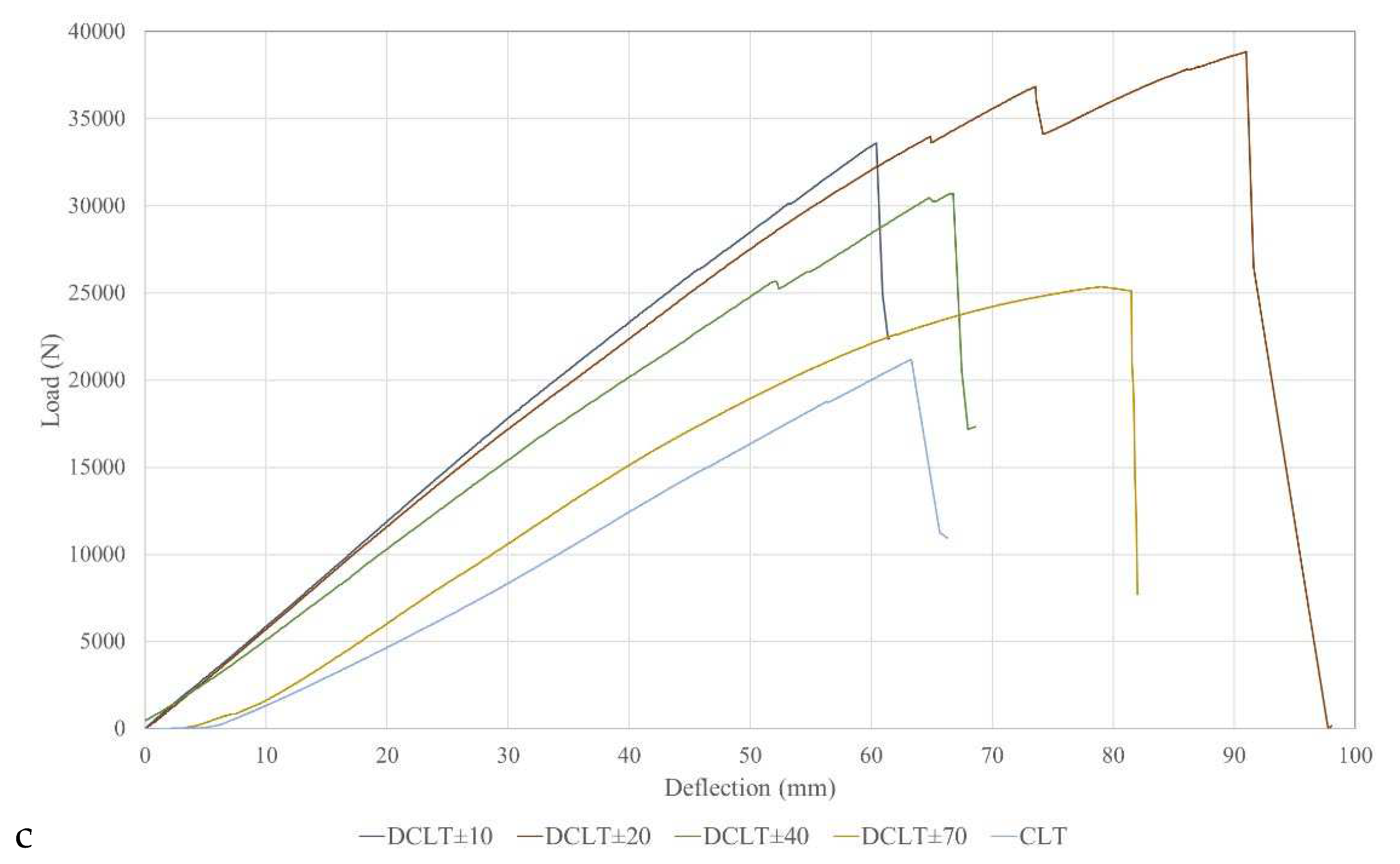
Figure 10.
Apparent Bending Stiffness of DCLT/ CLT Panels Predicted from Four Different Methods.
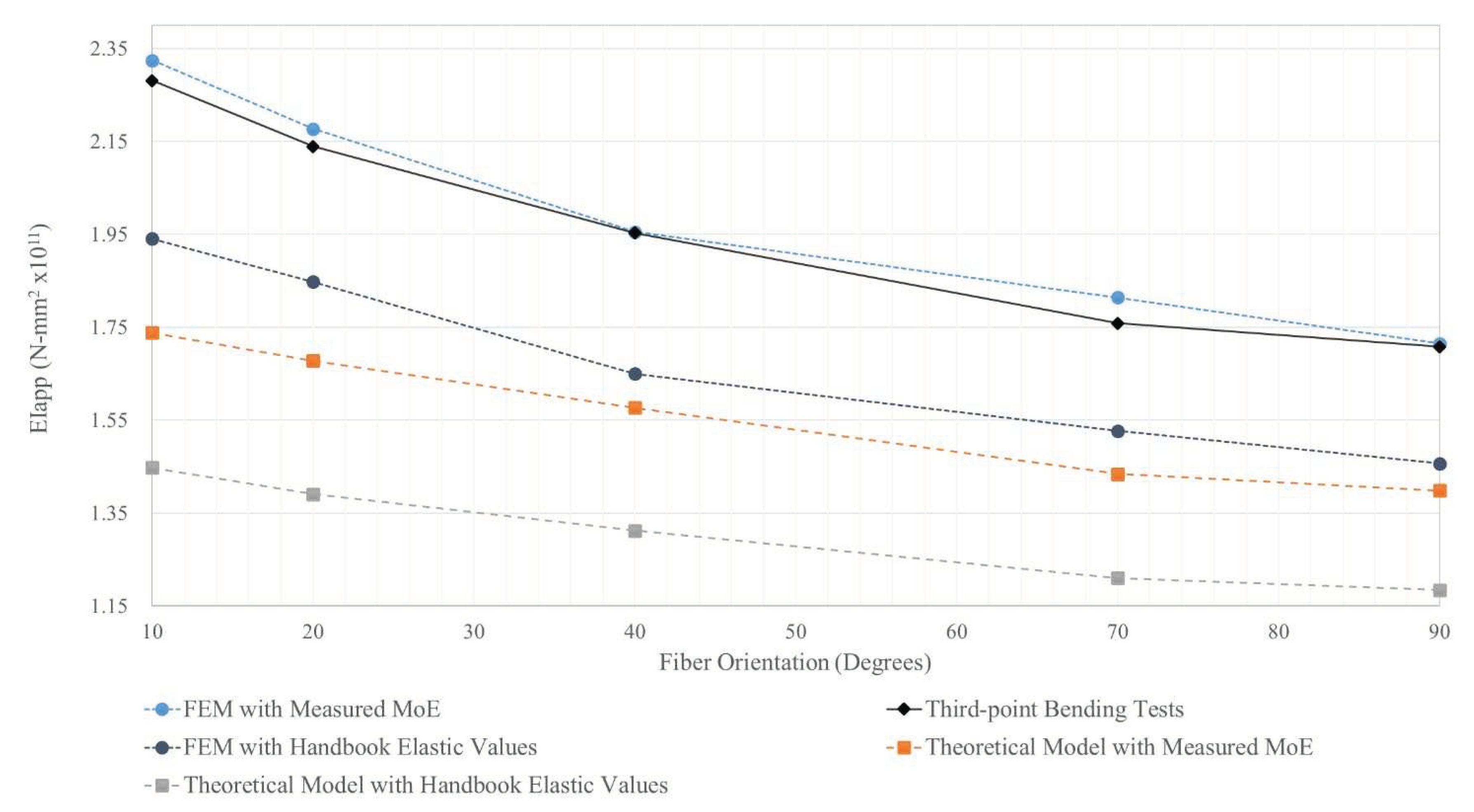

Table 1.
The ANSYS Properties (black locust and eastern white pine) Input for DCLT Panels.
| Species | Poisson’s ratio | Shear Modulus (MPa) | Young’s Modulus (MPa) | Specific Gravity | ||||||
| νlt | νlr | νtr | Glr | Glt | Grt | Et | Er | El | SG | |
| Black locust (Wood Handbook MoE) |
0.286 | 0.220 | 0.196 | 1,301 | 899 | 274 | 862 | 1,697 | 14,134 | 0.69 |
| Eastern White Pine (Wood Handbook MoE) |
0.233 | 0.223 | 0.220 | 624 | 592 | 76 | 467 | 766 | 8,549 | 0.35 |
| Black locust (Measured MoE) |
0.286 | 0.220 | 0.196 | 1,587 | 1,096 | 334 | 1,051 | 2,070 | 17,236 | 0.69 |
| Eastern White Pine (Measured MoE) |
0.233 | 0.223 | 0.220 | 548 | 520 | 67 | 411 | 673 | 7,515 | 0.35 |
Table 2.
Mesh Sizing and Details for ANSYS Modeling.
| Group | Bounding Box Diagonal Size (cm) | Average Surface Area (cm2) | Minimum Edge Length Size (cm) | Numbers of Nodes | Number of Elements |
| DCLT ±10 | 276.93 | 803.67 | 0.96 | 2,111,626 | 413,142 |
| DCLT ±20 | 276.93 | 584.96 | 0.12 | 1,983,392 | 387,159 |
| DCLT ±40 | 277.08 | 383.61 | 0.43 | 1,466,501 | 283,758 |
| DCLT ±70 | 276.93 | 322.12 | 1.90 | 388,696 | 66,528 |
| CLT | 276.93 | 307.03 | 1.90 | 913,030 | 174,240 |
Table 3.
Bending Stiffness Properties for Different Grain Orientations Obtained from Hankinson’s Theory.
Table 3.
Bending Stiffness Properties for Different Grain Orientations Obtained from Hankinson’s Theory.
| EIApp (N-mm2x1011) |
|||||
| 10° | 20° | 40° | 70° | 90° | |
| Handbook Values | 1.45 | 1.39 | 1.31 | 1.21 | 1.18 |
| MoE of the Layers | 1.74 | 1.68 | 1.58 | 1.43 | 1.40 |
| % Increase to CLT | 23% | 18% | 12% | 3% | -- |
Table 4.
Bending Stiffness Properties for Different Grain Orientations Obtained from Experimental Tests.
Table 4.
Bending Stiffness Properties for Different Grain Orientations Obtained from Experimental Tests.
| EIApp. (N-mm2x1011) |
Grain Orientation | ||||
|---|---|---|---|---|---|
| 10° | 20° | 40° | 70° | 90° | |
| Mean | 2.28 | 2.14 | 1.95 | 1.76 | 1.71 |
| % Increase to CLT | 33% | 25% | 14% | 3% | -- |
| CV | 2.62 | 5.93 | 3.37 | 7.42 | -- |
| Min | 2.23 | 2.00 | 1.90 | 1.67 | 1.71 |
| Max | 2.35 | 2.26 | 2.02 | 1.91 | 1.71 |
Table 5.
Bending Stiffness Properties for Different Grain Orientations Obtained from FEM Simulations.
Table 5.
Bending Stiffness Properties for Different Grain Orientations Obtained from FEM Simulations.
| EIApp (N-mm2x1011) |
Grain Orientation | ||||
| 10° | 20° | 40° | 70° | 90° | |
| Handbook Values | 1.94 | 1.85 | 1.65 | 1.53 | 1.46 |
| MoE of the Layers | 2.32 | 2.18 | 1.96 | 1.81 | 1.72 |
| % Increase to CLT | 33% | 26% | 13% | 6% | -- |
Disclaimer/Publisher’s Note: The statements, opinions and data contained in all publications are solely those of the individual author(s) and contributor(s) and not of MDPI and/or the editor(s). MDPI and/or the editor(s) disclaim responsibility for any injury to people or property resulting from any ideas, methods, instructions or products referred to in the content. |
© 2024 by the authors. Licensee MDPI, Basel, Switzerland. This article is an open access article distributed under the terms and conditions of the Creative Commons Attribution (CC BY) license (http://creativecommons.org/licenses/by/4.0/).
Copyright: This open access article is published under a Creative Commons CC BY 4.0 license, which permit the free download, distribution, and reuse, provided that the author and preprint are cited in any reuse.


