Submitted:
26 January 2024
Posted:
06 February 2024
Read the latest preprint version here
Abstract
The space shuttle, a revolutionary spacecraft that has played a significant role in human space exploration, was composed of various advanced materials that were carefully selected to meet the extreme demands of spaceflight. This review paper provides a comprehensive examination of the materials historically employed in the construction of space shuttles and explores the latest trends shaping the field. The evolution of space shuttle materials is traced from the inception of the space program to contemporary missions, highlighting key milestones, challenges, and breakthroughs. Emphasis is placed on the critical role that materials play in the overall performance, safety, and sustainability of space shuttles. The paper begins by elucidating the diverse requirements that materials must fulfill in the harsh and complex environment of space, encompassing extreme temperatures, radiation exposure, and mechanical stresses. A detailed analysis of the materials utilized in the fabrication of various shuttle components, such as thermal protection systems, structural elements, and propulsion systems, is presented. Special attention is given to the challenges posed by re-entry and the strategies employed to mitigate heat-related issues. Furthermore, the review explores recent innovations and emerging materials that are reshaping the landscape of space shuttle design. Advancements in nanotechnology, composite materials, and additive manufacturing are discussed in the context of their potential applications for enhancing shuttle performance and reducing mission costs. The paper also addresses the importance of sustainability in space exploration, exploring materials with lower environmental impact and improved recyclability. The review concludes with a forward-looking perspective on the future of materials, considering ongoing research, development, and the potential incorporation of cutting-edge technologies. Insights are provided into how the evolving landscape of materials science may influence the design and manufacturing processes of the next generation of space vehicles. This paper provides an overview of the materials used in the construction of the space shuttle, including their properties, applications, and challenges. The materials used in the space shuttle are critical in ensuring the safety, performance, and longevity of the spacecraft, and understanding their characteristics and performance in space is crucial for the advancement of aerospace engineering.
Keywords:
Space Shuttle
; Materials
; Thermal Protection Systems
; Structural Materials
; Propulsion Systems
; Re-entry
; Nanotechnology
; Composite Materials
; Additive Manufacturing
; Materials Science
; Emerging Materials.
1. Introduction
The space shuttle, officially known as the Space Transportation System (STS), was a reusable spacecraft that was designed and operated by NASA for human spaceflight missions. The space shuttle was composed of multiple components, including the orbiter, external tank, and solid rocket boosters, each constructed using different materials to meet their specific requirements. The materials used in the space shuttle had to withstand extreme conditions, including high tem- peratures, vacuum, radiation, and micrometeoroid impacts, while providing structural integrity, thermal protection, and other functional properties. Space exploration has been a remarkable human endeavour, with the space shuttle program serving as a pioneering milestone in the his- tory of aerospace technology. The space shuttle, a reusable spacecraft developed by NASA, revolutionized human spaceflight by providing a reliable and versatile means of transportation for astronauts and payloads to and from space. The success of the space shuttle program relied heavily on the materials used in its construction, which had to withstand the extreme condi- tions of space, including temperature variations, vacuum, radiation, micrometeoroid impacts, and space debris. Additionally, the materials used in the space shuttle had to meet stringent safety and reliability requirements to ensure the success and safety of human spaceflight missions. This paper provides an overview of the materials used in the space shuttle, including compos- ites, metals, ceramics, and other specialized materials, as well as the challenges, advancements, and opportunities in materials science and engineering for space applications. The materials used in the space shuttle were carefully selected to meet the demanding requirements of space travel. One of the key considerations was weight reduction, as every kilogram of mass added to the spacecraft meant more propellant needed for launch. Therefore, lightweight materials with high strength and stiffness were essential to minimize the overall mass of the space shuttle. Composites, which are materials made from two or more distinct materials combined together to create a material with improved properties, played a crucial role in the construction of the space shuttle. Composite materials, such as carbon fibre-reinforced polymers (CFRPs), were used extensively in the structure of the space shuttle, including the wings, tail, and body, due to their excellent strength-to-weight ratio and resistance to fatigue and corrosion. Metals were also used in various components of the space shuttle, particularly for their structural strength and thermal stability. For example, aluminium alloys were used in the construction of the space shuttle’s external tank due to their lightweight nature and excellent corrosion resistance. Tita- nium alloys were used in critical components such as the landing gear due to their high strength and low density. Additionally, stainless steel was used in some structural components due to its high strength, heat resistance, and durability. Ceramic materials were used in the space shuttle for their unique properties, including high-temperature resistance and thermal insulation. For instance, ceramic tiles made from materials such as silica and alumina were used in the shut- tle’s heat shield to protect it from the extreme heat generated during re-entry. These tiles were carefully designed and installed to provide effective thermal protection to the shuttle’s structure and keep the astronauts safe. Apart from composites, metals, and ceramics, the space shuttle also used other specialized materials, such as ablative materials for thermal protection, radiation shielding materials for crew safety, and insulation materials for temperature control. Ablative materials, which burn away during re-entry to absorb heat and protect the spacecraft, were used in areas of the space shuttle that experienced the highest temperatures, such as the leading edges of the wings and the nose cone. Radiation shielding materials, such as lead and polyethylene, were used to protect the astronauts from harmful radiation in space. Insulation materials, such as foams and films, were used to control temperature variations inside the spacecraft and protect sensitive components from extreme temperature changes. The paper organisation is as follows: The Significance of Materials in Space Shuttle Design is discussed in Section 2. The Historical Overview of Space Shuttle Materials are reviewed and discussed in Section 3. The Evolution of Materials over Different Shuttle Models and Key Requirements for Space Shuttle Materials are discussed in Section 4, and Section 5, respectively. The Primary Materials Used in Space Shuttle Construction are discussed in Section 6. Thermal Protection System (TPS) Materials are discussed in Section 7. Design and Material Requirements for Spacecraft are discussed in Section 8. Structural materials are discussed in Section 9. Challenges and Future Directions are discussed in Section 10. Conclusions are discussed in Section 11.
2. Significance of Materials in Space Shuttle Design
The materials incorporated into the space shuttle were mandated not only to adhere to stringent performance criteria but also subjected to exhaustive testing and qualification processes to ascertain their safety and reliability. Rigorous assessments, spanning mechanical, thermal, and environmental testing, were executed to scrutinize the properties and performance of these materials under conditions akin to those encountered in space. Testing parameters encompassed resistance to temperature fluctuations, vacuum exposure, radiation, micrometeoroid impacts, space debris encounters, as well as evaluations for durability, fatigue, and corrosion resistance. Materials successfully passing these evaluations underwent qualification for integration into the space shuttle, accompanied by stringent quality control measures during manufacturing and assembly. Advancements in materials science and engineering have played a pivotal role in shaping the materials employed in the space shuttle. Continuous research and innovation have resulted in the formulation of novel materials boasting enhanced properties, including heightened strength, reduced weight, superior thermal stability, and augmented radiation resistance. Notably, the integration of advanced composites, such as carbon nanotube-reinforced composites [1,2], holds promise for achieving superior strength-to-weight ratios, rendering them ideal for forthcoming space applications. Nanomaterials, including nanocomposites and nanocoatings [3,4], have been explored for their unique attributes, such as increased toughness, heightened thermal and electrical conductivity, and improved radiation resistance.
Furthermore, additive manufacturing, colloquially known as 3D printing, has emerged as a transformative technology for fabricating intricate and lightweight structures with customizable properties. Its application in producing specific components of the space shuttle, such as small-scale structural elements and prototypes, suggests potential for broader utilization in subsequent space missions. The prospect of printing materials in space using in-situ resource utilization (ISRU), where materials indigenous to space, such as lunar regolith or Martian soil, serve as raw materials for manufacturing, presents a revolutionary prospect for space exploration, reducing reliance on Earth-based materials.
In addition to material advancements, the evolution of advanced modeling and simulation techniques has substantially contributed to comprehending and optimizing materials for space applications. Computer simulations, finite element analysis, and computational materials science empower researchers and engineers to design and refine materials tailored to meet the specific requirements of space travel.
The materials employed in the space shuttle played a pivotal role in the triumph of the space shuttle program. Carefully chosen and qualified composites, metals, ceramics, and other specialized materials addressed the exacting demands of space travel, encompassing weight reduction, high strength, thermal stability, radiation resistance, and durability. Advances in materials science and engineering, featuring advanced composites, nanomaterials, additive manufacturing, and simulation techniques, have not only contributed to current achievements but also hold immense potential for shaping the materials of the future in space applications.
3. Historical Overview of Space Shuttle Materials
The emergence of the space shuttle marked a transformative era in space exploration, compelling the utilization of advanced materials capable of withstanding the rigorous conditions encountered in space travel. A comprehensive historical overview of space shuttle materials illuminates a progressive trajectory from the early programs to the sophisticated systems of subsequent models. The inception of space shuttle materials can be traced to early programs like the Space Shuttle Enterprise, serving as a prototype for subsequent shuttles. In this formative period, materials confronted the initial challenge of meeting the demands of an innovative design enabling reusable space travel. Aluminum alloys, renowned for their lightweight properties, emerged as primary materials in the structural components of the early shuttles, setting the foundation for the continuous evolution of space shuttle materials [5].
As space shuttle technology advanced, corresponding developments unfolded in the materials employed in their construction. The transition from the prototype phase to operational shuttles, including Columbia, Challenger, Discovery, Atlantis, and Endeavour, witnessed a refinement in material selection. A defining feature of this evolution was the introduction of advanced composites, contributing to heightened strength and reduced weight. The Challenger disaster in 1986 instigated a thorough reevaluation of materials, driving enhancements in safety and reliability. Subsequent shuttle models incorporated lessons learned, integrating more robust materials and prioritizing safety considerations.
The historical evolution of space shuttle materials underscores the escalating emphasis on meeting stringent performance requirements. The demanding conditions of space travel, encompassing extreme temperature variations, vacuum exposure, radiation, micrometeoroid impacts, and encounters with space debris, necessitated materials exhibiting exceptional durability, fatigue resistance, and corrosion resistance. With each new shuttle model, materials underwent rigorous testing and qualification processes to ensure their capability to withstand these challenges. The history of space shuttle materials is intricately linked with advancements in materials science and engineering. Research and innovation over the years have led to the development of new materials boasting improved properties, including higher strength, lower weight, better thermal stability, and enhanced radiation resistance. The integration of advanced composites, exemplified by carbon nanotube-reinforced composites, represents a substantial leap forward, offering even higher strength-to-weight ratios and showcasing the ongoing commitment to pushing the boundaries of materials science in the realm of space exploration.
4. Evolution of Materials over Different Shuttle Models
The progression of materials employed in space shuttles is a pivotal facet of aerospace engineering and technological advancement. NASA’s Space Shuttle program, spanning multiple decades, oversaw the development of five operational shuttles: Columbia, Challenger, Discovery, Atlantis, and Endeavour. Throughout the program’s duration, materials utilized in constructing these shuttles underwent a transformative evolution aimed at improving performance, safety, and efficiency. The materials used in the space shuttle are critical for ensuring the safe and successful operation of the spacecraft during its missions. Over the years, extensive research has been conducted to develop and select materials with the necessary properties to withstand the extreme conditions of space travel, including high temperatures, thermal cycling, vacuum, radiation exposure, and mechanical stresses. In this literature review, we will explore the key materials used in the space shuttle and their properties, as well as advancements in materials science and engineering that have contributed to their development. One of the key materials used in the space shuttle is advanced composites. Composite materials are created by combining two or more different ma- terials having contrasting qualities. Carbon fibre-reinforced composites, in particular, have been widely used in the space shuttle because of their favourable strength-to-weight ratio, excellent thermal stability, and low thermal expansion. These composites are used in various structural components of the space shuttle, such as the body panels, wings, and tail, to reduce weight while maintaining structural integrity. Metals are also crucial materials in the space shuttle, especially for components that require high strength and durability. Aluminium alloys, titanium alloys, and stainless steel are commonly used in the space shuttle for their superior mechanical qualities, such as high strength and low density, and good corrosion resistance. These metals are used in components such as the main propulsion system, landing gears, and structural supports. Ceramic materials are another important class of materials used in the space shuttle. Ceramics are known for their excellent thermal and chemical stability, making them suitable for high- temperature environments encountered when re-entering the atmosphere of the Earth. Ceramic tiles, made of materials such as silica, alumina, and zirconia, are used on the underside of the to shield the space shuttle from the high heat produced upon re-entry. In addition to composites, metals, and ceramics, other specialized materials are used in the space shuttle for specific appli- cations. For example, ablative materials are used in the nose cone of the shuttle to protect it from the heat of atmospheric entry. Ablative materials undergo controlled burning and charring to dissipate heat and protect the underlying structure. Thermal protection coatings, such as thermal barrier coatings and heat-resistant paints, are also applied to various components of the shuttle to protect them from high temperatures. The development of materials with improved qualities for applications aboard the space shuttle has been aided by developments in materials science and engineering. For instance, research has focused on developing advanced compos- ites with higher strength and improved thermal stability, such as carbon nanotube-reinforced composites. Nanomaterials, including nanocomposites and nanocoating, have also been explored for their unique properties, such as enhanced mechanical, thermal, and electrical properties.
Metals play a crucial role as fundamental materials in the construction of space shuttles, contributing to the spacecraft’s structural integrity, thermal management, and overall performance in the demanding conditions of space travel. Aluminum alloys, prized for their lightweight properties, find extensive use in various structural components, including the fuselage and frame, where strength and weight considerations are paramount. Titanium alloys, known for their high strength and heat resistance, are employed in critical structural and thermal components, ensuring durability in the face of extreme conditions during launch and re-entry. Stainless steel, valued for its corrosion resistance, is utilized in components subjected to environmental exposure. Inconel and other high-temperature alloys, with their heat-resistant properties, are specifically chosen for applications in areas experiencing extreme thermal conditions.The structural applications of metals extend to the construction of load-bearing components such as wings, fins, and landing gear, where considerations of stress, strain, and impact resistance are vital. Moreover, metals contribute to the thermal properties of the spacecraft, facilitating efficient heat dissipation and playing a role in thermal protection systems (TPS) that shield the shuttle from the intense heat generated during re-entry. Despite the advantages of metals, challenges such as thermal stress, fatigue, and corrosion in the space environment necessitate sophisticated mitigation strategies and coating technologies. Advancements in metal technologies have seen the development of high-strength alloys and the integration of lightweight metals to enhance overall performance. Additionally, additive manufacturing techniques have opened new possibilities for fabricating intricate metal structures with improved efficiency. As space exploration evolves, the ongoing exploration of new metal alloys and their integration into next-generation spacecraft underscores the enduring significance of metals as foundational materials in the continued quest for space exploration and discovery
4.1. Aluminum and Titanium Alloys
4.2. Reinforced Carbon–Carbon (RCC)
The highest re-entry heating areas of the NASA Space Shuttle were protected with a specially processed Reinforced Carbon–Carbon (RCC) material. Both the wing leading edge and the nose-cap assembly were fabricated from the RCC material. To initiate the fabrication of the RCC material, a precursor woven fabric was layered in such a way that all plies alternated in the 0 and 90-degree direction. During the processing, silica was infused into the outer 2–3 laminae, and the resulting laminate was heated in an inert environment to form a silicon-carbide (SiC) coating. This SiC coating was necessary to provide oxidation protection to the Space Shuttle Orbiter’s wing leading edge during the high heating experienced on re-entry into the Earth’s atmosphere. The high-temperature processing resulted in voids in the carbon–carbon substrate and micro-cracks in the SiC coating.Vital areas such as the leading edges of the wings were shielded by reinforced carbon–carbon, a composite material renowned for its capability to endure high temperatures during re-entry [8].
4.3. Self-healing materials for space application
Space exploration and interplanetary colonisation require long-lasting, extremely reliable and self adaptable space materials which can repair autonomously if spacecraft systems and structures are damaged. Conventionally engineered materials used in space applications are vulnerable to mechanical, thermal, UV and chemical damage. Developing self-healing materials for spacecraft can lead to the realisation of safe and reliable space structures (space suits, optical surfaces, liquid-propellant containers and protective coatings), opening the possibility for longer-duration missions [9,10]. Spacecraft must withstand high radiation levels, extreme temperatures and the vacuum of space [11]. Extrinsic self-healing materials exhibit repeatable self-healing capabilities, but the challenge arises in the need for energy input to initiate the healing process, particularly in space. Hybrid films incorporating polymeric nanofillers such as carbides, titania nanomaterials, graphene, derivatives, and MXenes hold promise in various applications, ranging from EMI shielding and thermal management to self-cleaning surfaces and fire-resistant materials. Enhancing the performance and feasibility of these materials requires meticulous fine-tuning, optimization, and a comprehensive understanding of advanced material processing through effective coordination between level-specific modeling techniques.The identified areas for innovation present technical challenges that necessitate iterative and explorative improvements, crucial in their own right. Additionally, a broader outlook for space materials involves the ambitious goal of integrating multiple functionalities into a single component or material. For instance, merging self-healing technology with structural health-monitoring composites could enhance safety, longevity, and feasibility for space applications simultaneously. Similarly, spacecraft featuring intrinsically EMI shielding/energy-storing composite structural panels would reduce weight and profile, improving overall feasibility. The combination of self-healing materials with self-cleaning surfaces could result in scratch and dust-resistant coatings, enhancing the longevity of solar panels.While integrating numerous functionalities into a single material poses challenges in maintaining original functionalities, ongoing advancements in quantum computing and artificial intelligence offer the potential to overcome these hurdles through advanced materials modeling. Envisioning a satellite with structural panels serving as antennas and power sources, capable of shape morphing, self-healing, EMI shielding, self-cleaning, and thermal stability may become a reality with continuous progress in these fields. Until then, significant research is imperative in the realm of space materials.
4.4. Composites
Composites played a critical role in the construction of the space shuttle, particularly in the fab- rication of the orbiter. The orbiter, which served as the main vehicle for carrying astronauts and payloads to and from space, was made primarily of composite materials, including carbon fibres reinforced polymers (CFRP) and fiberglass composites. These materials offered high strength- to-weight ratios, excellent thermal stability, and low thermal expansion properties, making them ideal for aerospace applications. CFRP composites were used in the fabrication of structural components, such as the wings, fuselage, and tail, due to their high stiffness and strength, while fiberglass composites were used in non-structural components, such as fairings and access doors.
4.5. Other Materials
In addition to composites, metals, and ceramics, the space shuttle also used various other materials for different purposes. For example, the windows in the orbiter were made of fused silica, a type of glass that has high optical clarity and resistance to radiation. The thermal blankets used in the orbiter’s payload bay were made of flexible insulation materials, such as Mylar and Kapton, to protect sensitive payloads from extreme temperatures. The adhesives, sealants, and coatings used in the space shuttle were also carefully selected to meet the stringent require- ments of spaceflight, including low outgassing, high bond strength, and resistance to vacuum and radiation.
5. Key Requirements for Space Shuttle Materials
The materials used in space shuttles must meet stringent requirements to withstand the harsh conditions of space travel, re-entry into Earth’s atmosphere, and the stresses of launch and landing. Here are some key requirements for space shuttle materials:
Thermal Resistance for the Re-entry Heat Protection: Materials must be capable of withstanding extremely high temperatures experienced during re-entry into Earth’s atmosphere. This is often achieved through the use of heat-resistant materials such as reinforced carbon–carbon and thermal protection tiles. Structural Integrity: Space shuttle materials must provide the structural integrity needed to withstand the dynamic forces and vibrations experienced during launch, orbital operations, and landing.
Weight Efficiency: As weight is a critical factor in space travel, materials must be lightweight while maintaining strength. This requirement helps optimize fuel efficiency and payload capacity [12].
Aerodynamic Stability: Materials used in the construction of wings and other aerodynamic surfaces should provide stability and control during re-entry and landing. Protection Against Corrosion: Materials must resist corrosion due to exposure to the space environment, including the vacuum of space, radiation, and other corrosive elements [13].
Radiation Shielding: Space shuttles must incorporate materials that provide adequate shielding against cosmic radiation, which is more prevalent in space than on Earth.
Electromagnetic Interference (EMI) Shielding: mMaterials should be designed to minimize electromagnetic interference, which can affect the functioning of electronic systems on board.
Thermal Insulation: Effective insulation materials are crucial to regulate internal temperatures, protecting sensitive equipment from extreme temperature variations [14].
Safety Features: Materials should be fire-resistant to minimize the risk of combustion during launch and re-entry.
6. Primary Materials Used in Space Shuttle Construction
The harsh conditions to which the Space Shuttles are exposed during flight required the development and use of many unique materials. These materials were specially designed to withstand extreme temperatures, in some cases over 1600 C, while other material must withstand the cryogenic conditions of -253 C, and others must operate while under extreme loads. All of these materials must not only operate in the harsh condition but they must be light weight as well. The Space Shuttle is composed of three major components when configured for launch: the Shuttle, solid rocket boosters, and external tank (ET). The different heat shields of the Shuttle make up the thermal protection system (TPS); this system consists of many different types of components designed to operate on various parts of the vehicle. The body of the Shuttle and ET are composed mainly of aluminium alloy and graphite epoxy.
The TPS consists of reinforced carbon-carbon (RCC) used on the wing leading edges and nose cap areas while the upper forward fuselage areas, the entire underside of the Shuttle, the Orbiter maneuvering system, and reaction control system utilize black high temperature reusable surface insulation (HRSI) tiles. Other areas of the Orbiter are protected by fibrous refractory composite insulation (FRCI) tiles. Areas where the temperature stays below 649 C, such as the forward fuselage, mid-fuselage, aft fuselage, vertical tail, and upper wing, are protected by other material such as, white low temperature reusable surface insulation (LRSI) tiles, advanced flexible reusable surface insulation (AFRSI) blankets, and felt reusable surface insulation (FRSI) white blankets. The RCC is a pyrolized laminated carbon with the outer surface converted to silicon carbide to prevent oxidation. The FRSI tiles are made of a low-density, high purity silica 99.8-percent amorphous fiber insulation that is made rigid by ceramic bonding resulting in 90-percent void and 10-percent materials. The RCC and HRSI are used in areas where the temperature rises above 1260 T. The FRCI tiles are high strength tiles derived by adding alumina-bososilicate fiber to the pure silica tile slurry that welds the micron-sizes fibers of pure silica into a rigid structure during sintering. The FRCI is composed of 20-percent alumina-borosilicate fibers and 80-percent silica fibers, and provided improved strength, durability and resistance to coating cracking and weight reduction than HRSI.
The LRSI tiles composed of the 99.8-percent pure silica fibers while the AFRSI consists of low-density fibrous silica batting that is made of high purity silica and 99.8-percent amorphous silica fibers [15,16,17]. The FRSI, used on the upper payload bay doors and fuselage, consists of glass fibers, bonded directly to the orbiter by room temperature vulcanizing (RTV) silicon-adhesives.
Additional materials are used in other areas such as thermal panes for the windows, thermal barriers, and gap filler around operable penetrations. The external tank thermal protection system (El TPS) consists of sprayed-on foam insulation and remolded ablator materials. The system also includes the use of phenolic thermal insulator. The use of such a wide range of materials requires close attention to possible damage caused by debris. Post flight inspection of the TPS includes detailed analyses of any debris found on damaged parts. The results of these analyses are used to help determine the source of the debris to help prevent future damage [18,?,19].
The research of aircraft materials for structural and engine applications has advanced significantly in recent years. The aerospace industry has benefited greatly from the development of alloys such those based on aluminium, magnesium, titanium, and nickel. Innovative materials like composites are playing a more and bigger part in aircrafts. Recent aerospace materials still have significant problems with corrosion, stress corrosion cracking, fretting wear, and insufficient mechanical characteristics. In order to increase performance and life cycle costs, substantial research has been done to create the next generation of aerospace materials with improved mechanical performance and corrosion resistance. The following subjects are covered in this review: materials needed while designing aeroplane constructions and engines, as well as recent developments in the aerospace materials [19,20].
In several areas, including the aerospace industry, smart materials, sometimes known as intelligent materials, are steadily increasing relevance. It is because these materials have special qualities including self-sensing, self-adaptability, memory capability, and a variety of tasks. There has not been an assessment of smart materials for a while. Consequently, it is thought worthwhile to write a review on this topic. This paper discusses the developments in smart materials and how they can be used in the aerospace sector. Smart materials’ classification, operation, and most recent advances (nano-smart materials) are reviewed. Additionally, the materials’ potential applications in the future are underlined. There has not been a lot of research done in this subject; it needs more in-depth investigation [3].
Additive manufacturing, or a promising approach for creating intricate, lightweight structures with adaptable features is 3D printing. This technology has been used in the production of certain components of the space shuttle, such as small-scale structural components and prototypes, and has the potential for wider adoption in future space missions. In-situ resource utilization (ISRU), which involves using materials found in space as raw materials for manufacturing, has also been proposed as a way to reduce the reliance on Earth-based materials in space missions. Furthermore, advancements in modelling and simulation techniques have contributed to the understanding and optimization of materials for space applications. Computer simulations, finite element analysis, and computational materials science have enabled researchers and engineers to design and optimize materials with tailored properties to meet the specific requirements of space travel. The Space Shuttle design was heavily influenced by the requirement of the USAF for orbiting large spy satellites and conducting “black ops” missions. Such flights would be flown out of Vandenberg Air Force Base, where a new launch complex was built before the plan was cancelled following the Challenger accident. This chapter tells how the USAF and the intelligence organizations planned to use the Space Shuttle, what was achieved and what was lost, such as the polar mission of STS-61A. The Space Shuttle design was heavily influenced by the requirement of the USAF for orbiting large spy satellites and conducting “black ops” missions. Such flights would be flown out of Vandenberg Air Force Base, where a new launch complex was built before the plan was cancelled following the Challenger accident. This chapter tells how the USAF and the intelligence organizations planned to use the Space Shuttle, what was achieved and what was lost, such as the polar mission of STS-61A [21]. The research of aircraft materials for structural and engine applications has advanced significantly in recent years. The aerospace industry has benefited greatly from the development of alloys such those based on aluminium, magnesium, titanium, and nickel. Innovative materials like composites are playing a more and bigger part in aircrafts. Recent aerospace materials still have significant problems with corrosion, stress corrosion cracking, fretting wear, and insufficient mechanical characteristics. In order to increase performance and life cycle costs, substantial research has been done to create the next generation of aerospace materials with improved mechanical performance and corrosion resistance. The following subjects are covered in this review: materials needed while designing aeroplane constructions and engines, as well as recent developments in the aerospace materials [20]. In several areas, including the aerospace industry, smart materials, sometimes known as intelligent materials, are steadily increasing relevance. It’s because these materials have special qualities including self-sensing, self-adaptability, memory capability, and a variety of tasks. There hasn’t been an assessment of smart materials for a while. Consequently, it is thought worthwhile to write a review on this topic. This paper discusses the developments in smart materials and how they can be used in the aerospace sector. Smart materials’ classification, operation, and most recent advances (nano-smart materials) are reviewed. Additionally, the materials’ potential applications in the future are underlined. There hasn’t been a lot of research done in this subject; it needs more in-depth investigation [22]. The current research progress on the use of aerogel materials in aviation and aerospace applications. The paper provides a comprehensive overview of aerogel materials, their unique properties, and their potential applications in the aerospace industry. The authors also review recent advances in aerogel production and characterization techniques, as well as potential challenges and future directions for research. Researchers and engineers interested in the creation and use of aerogel materials in aerospace and aviation may find the paper to be a useful resource. The materials needs and research and development strategy for future military aerospace propulsion systems. The paper provides an overview of the challenges and opportunities for the development of advanced propulsion systems, including high-speed and hypersonic propulsion, and the associated materials requirements. The authors also offer suggestions for future research areas and an overview of the state of materials research and development for aeronautical propulsion systems. Researchers and engineers working on the creation of cutting-edge aircraft propulsion systems for military applications will find the study to be a useful resource [23]. The unique properties of polymeric materials that make them suitable for use in aerospace, such as their lightweight, high strength, and flexibility. The paper also reviews the challenges associated with the use of polymeric materials in aerospace, including issues related to thermal stability, durability, and flammability The authors also examine recent developments in the creation of sophisticated polymeric materials for usage in aircraft, such as shape memory polymers, polymer matrix composites, and nanocomposites. The paper provides information on the most recent research and development initiatives in the area, making it a valuable resource for researchers and engineers interested in the use of advanced polymeric materials for aeronautical applications [24]. The author discusses CGDS’s distinctive qualities, including its high deposition efficiency, minimal heat input, and capacity to deposit a variety of materials. The article also examines CGDS’s possible uses in the aerospace sector, such as the creation of protective coatings and thermal barrier coatings and repair of damaged components. Additionally, the author highlights recent advances in CGDS technology, such as the development of novel feedstock materials, and the use of computational modelling for process optimization. The document provides information on the most recent research and development initiatives in the area, making it a useful resource for academics and engineers interested in using CGDS for the creation of novel materials for aeronautical applications [25]. The authors talk about issues including impact damage, delamination, and cracking that might arise when using laminated materials in aircraft structures. The potential of SHM methods, such as acoustic emission, ultrasonic testing, and fiber-optic sensing, for identifying and keeping track of these kinds of damage is then discussed. The application of machine learning algorithms for data analysis and interpretation is one of the most recent developments in SHM technologies that are highlighted in the study. The document provides information on the most recent research and development initiatives in the area, making it a useful resource for scientists and engineers interested in using SHM processes for laminated materials in aeronautical applications [26]. The authors discuss the unique properties of composite materials that make them suitable for use in aerospace, such as their high strength-to-weight ratio, durability, and corrosion resistance. The paper also reviews the historical development of composite materials in aerospace, starting from early applications in military aircraft to modern-day commercial aircraft and space vehicles. Furthermore, the authors explore recent advancements in the development of aerospace composite materials, including the use of nanomaterials and bio-composites. The document provides information on the most recent research and development initiatives in the area, making it a valuable resource for academics and engineers interested in the background and future prospects of composite materials in aerospace [27]. The author reviews the unique characteristics of aerogels, such as their low thermal conductivity, light weight, and high porosity, which make them ideal for use in aerospace applications. The paper explores the spray deposition technique used to apply aerogels onto the fuel tank surfaces, providing insights into the process parameters and the resulting insulation performance. The author also highlights the benefits of using aerogels as insulation for space shuttle fuel tanks, such as improved fuel efficiency and increased safety. The paper serves as a valuable resource for researchers and engineers interested in the use of aerogels as thermal insulation in aerospace applications, providing insights into the latest research and development efforts in the field [28]. In the development of an advanced ceramic insulation system for the Space Shuttle Orbiter. The author highlights the challenges faced in designing an effective insulation system for the Space Shuttle, including the need for high-temperature resistance, low thermal conductivity, and the ability to withstand the harsh environment of space. The paper describes the development process of the ceramic insulation system, including the selection of materials and the manufacturing techniques used to produce the insulation tiles. The author also discusses the testing and evaluation of the insulation system, demonstrating its effectiveness in meeting the requirements of the Space Shuttle program. The paper serves as an important historical record of the development of the Space Shuttle’s external insulation system and provides valuable insights into the design and development of advanced materials for space applications [29]. The authors conducted finite element analysis to investigate the thermal performance of the aerogel insulation tiles under various conditions. The paper presents detailed simulations of the heat transfer in the insulation tiles, providing valuable insights into the thermal behaviour of the material. The authors also discussed the manufacturing process of the silica aerogel insulation tiles and evaluated the physical properties of the material. The paper concludes that silica aerogel is a promising candidate for high-temperature insulation tiles for the next generation space shuttle due to its low thermal conductivity and high-temperature resistance. The study provides valuable information for engineers and researchers working on the development of advanced insulation materials for space applications [30]. use of a material developed for the Space Shuttle insulation as a potential implant material for human bone. The paper presents the results of experiments conducted by researchers at NASA, who investigated the biocompatibility and mechanical properties of the Space Shuttle insulation material for use in orthopaedic surgery. The authors found that the material was biocompatible and had good mechanical properties, making it a promising candidate for use as an implant material. The study provides an example of how technology developed for space exploration can have practical applications in other fields, such as medicine. The paper also highlights the importance of collaboration between different fields of science and technology to develop innovative solutions for complex challenges [31]. challenges of developing insulation materials that can withstand the extreme temperatures encountered during spaceflight, while also being lightweight and reusable. The paper presents a new type of insulation material, called Multi-Layer Insulation (MLI), which consists of several layers of lightweight materials that are layered together to form an insulating blanket. The author discusses the benefits of using MLI, including its low mass and high thermal efficiency, which make it an ideal material for use in the Space Shuttle. The paper provides insights into the development of advanced insulation materials for space applications, highlighting the importance of innovation and collaboration in the field of aerospace engineering [32]. the various types of insulation materials and techniques that are used to insulate the Space Shuttle’s liquid hydrogen and oxygen tanks, which are critical components of the Shuttle’s propulsion system. The paper also provides insights into the challenges of developing cryogenic insulation materials that can withstand the extreme temperatures and pressures of spaceflight, while also being lightweight and cost-effective. The author emphasizes the need for continued research and development in cryogenic insulation technology, highlighting the important role that such materials play in the success of space missions. Overall, this paper provides valuable information on the development of advanced insulation materials for space applications, highlighting the important role that engineering plays in the field of aerospace technology [33]. The need for an external TPS to protect the Shuttle from the extreme temperatures and aerodynamic forces experienced during re-entry into Earth’s atmosphere. They outline the design and development of a lightweight and reusable insulation material, based on a ceramic fibre reinforced phenolic composite. The authors also discuss the testing and validation of the TPS, including high-temperature testing and impact resistance testing. The paper concludes with a discussion of the advantages of this reusable TPS over previous designs, including reduced weight and cost, and increased safety and reliability. This paper provides valuable insights into the engineering and design considerations involved in the development of advanced thermal protection systems for aerospace applications [34]. Manufacturing challenges in producing the high-temperature reusable surface insulation for the thermal protection system of the Space Shuttle. The author begins by providing a brief overview of the Space Shuttle’s thermal protection system and its primary insulation material, LI-900. He then goes on to describe the complex manufacturing process involved in producing LI-900, including the mixing, extrusion, and curing stages. The author notes that the process is highly sensitive to variations in temperature, humidity, and other environmental factors, which can lead to significant variations in the final product’s properties. Finally, Forsberg discusses several quality control measures that were implemented to ensure the consistent quality of the insulation material, including extensive testing and inspection procedures. Overall, the paper provides valuable insights into the challenges of producing a high-performance insulation material for one of the most critical components of the Space Shuttle’s thermal protection system [35]. the different types of mechanical attachment systems that were considered, including the "Z-pin" and "Vespel pin" methods, as well as the challenges associated with each method. Ultimately, the authors concluded that the "Z-pin" method was the most suitable for the Space Shuttle, as it provided the necessary level of attachment strength while also allowing for easy tile removal and replacement during maintenance. The report offers insightful information on the design concerns and difficulties related to the Space Shuttle’s thermal protection system [36]. The foam material is a rigid polyurethane foam, which was used to insulate the space shuttle external fuel tank. The authors conducted experiments using single edge notch bend (SENB) specimens to measure the fracture toughness of the foam material. The results showed that the fracture toughness of the foam material decreases with an increase in the density of the foam. The paper also highlights the importance of understanding the fracture toughness of the foam material, which is critical in ensuring the safety of the space shuttle during its operation [37]. The insulation system, including the selection of materials, and the requirements for thermal performance. The authors then present the results of thermal tests on insulation samples, including measurements of thermal conductivity, heat capacity, and thermal expansion. The data obtained from the tests were used to develop mathematical models for predicting the thermal behaviour of the insulation system under different operating conditions. The paper concludes with a discussion of the implications of the results for the design and operation of the Space Shuttle [38]. The study used high-speed cameras and a laser displacement sensor to capture data during the rocket motor firing. The findings demonstrated that locations with separated or turbulent flow had greater insulation material erosion rates. This finding is important for improving the design of rocket motor insulation materials to withstand harsh environmental conditions during space missions. The study provides valuable insights into the erosion behaviour of rocket motor insulation materials that can be used for developing more durable and reliable insulation systems for future space exploration [39].
7. Thermal Protection System (TPS) Materials
The orbiter’s foremost defense against the intense heat experienced during re-entry is its Thermal Protection System (TPS). In the face of extreme temperatures and air deflections upon return, the orbiter must demonstrate resilience. Each atmospheric entry results in the loss of several TPS tiles; however, as long as they are not uniformly dislodged from a single location, the orbiter remains secure. Comprising ceramic materials, these tiles are engineered to endure temperatures approaching 3,000 degrees Fahrenheit. With a staggering count exceeding 27,000 tiles on the shuttle, each holds equal significance in safeguarding the orbiter’s structural integrity and ensuring a successful return journey.
The thermal protection system (TPS) is a crucial component comprised of diverse materials strategically applied to the outer surface of the orbiter, serving as the primary defense against extreme temperatures, particularly during re-entry into the Earth’s atmosphere. Positioned as the final barrier preceding the aluminum and graphite epoxy shell, the TPS materials play a pivotal role in safeguarding the orbiter’s structural integrity.
Operating within a temperature spectrum ranging from minus 250 degrees Fahrenheit during the cold soak of space to entry temperatures approaching nearly 3,000 degrees Fahrenheit, the TPS materials demonstrate exceptional resilience. As an external layer on the orbiter’s skin, the TPS not only shields the spacecraft from the intense heat but also shapes its aerodynamics, effectively establishing the vehicle’s profile as it hurtles through the atmosphere.
Constituting a passive system, the TPS is meticulously designed with materials selected for their stability at high temperatures and their efficiency in terms of weight. This selection process ensures that the TPS operates as a reliable and effective heat shield, contributing to the overall success and safety of the orbiter during its re-entry and descent.
7.1. Overview of TPS
The space shuttle is a complex spacecraft that operates in extreme environments, including the vacuum of space and extreme temperatures ranging from extreme heat during re-entry to extreme cold in space. The materials used in the space shuttle must be carefully selected and designed to withstand these harsh conditions and ensure the safety and functionality of the spacecraft. One critical aspect of spacecraft design is insulation, which is used to prevent the transfer of heat and cold between different spacecraft components, as well as to protect astronauts from temperature extremes. In this section, we will discuss the various insulation methods used in the space shuttle to prevent heat and cold transfer. The TPS is made of a variety of materials, including high-temperature ceramic tiles and reinforced carbon-carbon (RCC) that can endure temperatures of up to 3,000 degrees Fahrenheit. These materials’ superior thermal insulation capabilities shield the space- craft’s underlying structure from damage by preventing heat from accessing it. While ceramic tiles are utilised in some portions of the shuttle, like the belly and sides, RCC is used on the nose cap and leading edges of the wings.
7.1.1. Insulation Blankets
Insulation blankets are used in the space shuttle to prevent the transfer of heat and cold between different spacecraft components. These blankets are made of high-performance materials, such as multi-layered insulation (MLI) blankets, which are made up of low-conductivity spacers between layers of reflective foil in numerous layers. The reflective foil reflects and radiates heat away from the spacecraft, while the spacers reduce conductive heat transfer. MLI blankets are used in various areas of the spacecraft, including the payload bay, external tanks, and other critical components to prevent heat build-up during orbital operations and protect against extreme cold in space.
7.1.2. Cryogenic Insulation
The space shuttle uses cryogenic insulation to prevent the transfer of heat to the cryogenic propellant tanks, which store and handle cryogenic fuels, such as liquid hydrogen and liquid oxygen. Cryogenic insulation is essential to maintain the low temperatures required for these fuels to remain in their liquid state. Materials such as foam insulation, vacuum-jacketed lines, and cryogenic blankets are used to insulate the cryogenic tanks and prevent heat transfer from the surrounding environment.
7.1.3. Structural Insulation
Structural insulation is used in the space shuttle to protect the spacecraft’s structure from ex- treme temperatures. This insulation is typically used in areas where the spacecraft structure is exposed to high heat, such as near the engines and rocket nozzles. Structural insulation ma- terials, such as phenolic impregnated carbon ablator (PICA) and avocet, are designed to char and ablate when exposed to high heat, forming a protective layer that prevents the heat from penetrating the underlying structure.
7.1.4. Activated Thermal Control Systems
Activated thermal control systems are also used in the space shuttle to regulate temperature and prevent heat and cold transfer. These systems use various techniques, such as heaters, coolers, and heat exchangers, to actively control the temperature of different spacecraft components, including avionics, payload, and life support systems. Maintaining the necessary temperature range for delicate spacecraft components and ensuring their effective operation requires active thermal control systems. The space shuttle employs various insulation methods to prevent the transfer of heat and cold and protect the spacecraft and astronauts from extreme temperatures. These insulation methods include the Thermal Protection System (TPS) for re-entry heat pro- tection, insulation blankets, cryogenic insulation for propellant tanks, structural insulation, and active thermal control systems.
7.2. Materials for temperature regulation
Surface modifications, coatings, or the use of multi-layer insulating blankets are all examples of passive heat management techniques for spacecraft. Metals frequently need surface treatment prior to launch in order to stop corrosion. Hexavalent chromate, which is frequently used in chemical conversion coatings, is now subject to further restrictions because of environmental protection laws. Chromium-free alternatives or trivalent chromium may be used in more recent conversion coatings. Ongoing testing is being done to evaluate how well these coatings resist corrosion and how they affect the environment in space.
Chemical conversion coatings in accordance with MIL-C-5541 provide adequate corrosion protection, however because of their generally low thermal emittance, they would not be able to maintain the required temperature while in orbit. Man-made spacecraft, especially those that do extravehicular activities (EVAs or spacewalks), must adhere to more stringent heat management specifications to maintain safe contact temperatures between -118 and +113 ∘C (-180 and +235 ∘F). The comfort and safety of astronauts during space missions depend on taking these thermal control issues into account.
Anodizing in accordance with MIL-A-8625 is advised to achieve improved passive thermal regulation in terms of absorbance and emittance. Three different types of anodize are listed in MIL-A-8625: Type I chromic acid (which is practically eliminated due to the use of less chromate), Type II sulfuric acid (processed with a hot water seal for space exposure), and Type III hard anodize (used for wear resistance with a thicker oxide layer). Hard anodizing on parts that are prone to fatigue, however, needs to be carefully considered. When desirable thermal qualities cannot be reached with sulfuric acid anodized aluminum without compromising corrosion protection, phosphoric acid anodize and boric/sulfuric acid anodize may be suitable. Both have been tested in space. Passive heat control coatings or paints are utilised when a reduced absorptance/emittance ratio is required. Those suitable for spacecraft usage frequently contain binders like silicone, epoxy, polyurethane, or potassium silicate. Paints with an acrylic base work badly in space. Due to atomic oxygen erosion, polyurethane and epoxy coatings have a finite lifetime in low Earth orbit. When some UV darkening is acceptable or when complex geometries cause adhesion issues, silicone coatings, often of the low-outgassing variety, are appropriate. However, care must be taken when applying silicone coatings in direct line of sight with delicate optics. Potassium silicate coatings are resistant to contamination and long-lasting in space, however they can be difficult to apply. It is crucial to adhere to the manufacturer’s suggested cure times because premature exposure can result in cracking and debonding. Coatings ought to be examined at conditions similar to the extremes experienced while in space, which might require a thermal vacuum bakeout.
Figure 1.
Anodized aluminium breakdown in a plasma environment [40]
Figure 1.
Anodized aluminium breakdown in a plasma environment [40]
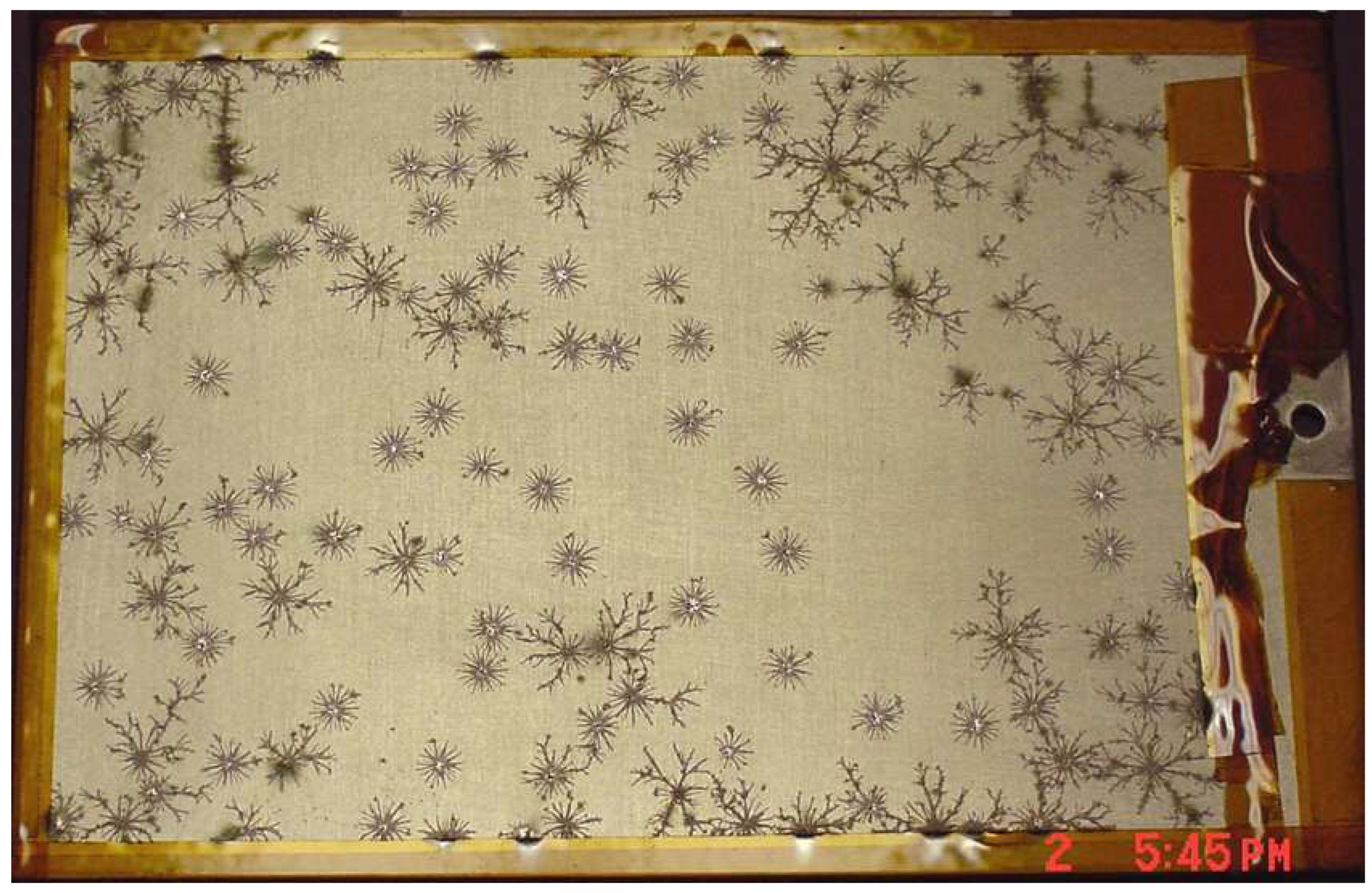
The breakdown of the anodised layer on aluminium or operational abnormalities are possi- ble outcomes of passive thermal control coatings and anodizes accumulating surface charge in the space environment. In NASA RP-1390, system failures brought on by spacecraft charging incidents are highlighted, including satellite control loss. Surface charge can be reduced and harm avoided by using static-dissipative materials or conductive coatings. Thin films coated with indium tin oxide have been utilised, although caution must be used to prevent breaking. Additionally, conductive thread sewn into fibreglass cloth has been used.
7.3. Thermal Protection System (TPS) Materials and Their Applications
Thermal protection materials play a critical role in space exploration, serving to endure extreme temperatures during engine exhaust or re-entry, which can reach up to 2,800∘C (5,070∘F). These materials are meticulously chosen for their ability to withstand the demanding conditions encountered during space missions. Here, we delve into two key materials within the Thermal Protection System (TPS): Reinforced Carbon-Carbon (RCC) and Black High-Temperature Reusable Surface Insulation (HRSI) tiles.
7.3.1. Reinforced Carbon-Carbon (RCC)
Reinforced carbon-carbon (RCC) is strategically applied to critical regions of the orbiter, including wing leading edges, the nose cap, and the vicinity around the forward or biter/external tank structural attachment. This material acts as a thermal barrier, shielding these areas from temperatures surpassing 2,300 degrees Fahrenheit during re-entry.
The production process of RCC tiles involves a multi-step procedure to achieve optimal carbon-carbon properties. Initially, a graphitized rayon cloth is impregnated with phenolic resin, undergoing curing and pyrolysis cycles. The outer surface is coated with silicon carbide to prevent oxidation. A high-temperature treatment in a controlled environment leads to a diffusion reaction, converting outer layers to silicon carbide, providing a protective barrier.
To address potential surface cracks in the silicon carbide coating due to thermal expansion mismatch, the RCC part is impregnated with tetraethyl orthosilicate, ensuring uniform thermal expansion. The resulting RCC laminate, preferred for its lightweight and robust characteristics, operates effectively in extreme temperature variations, ranging from minus 250 degrees Fahrenheit to about 3,000 degrees Fahrenheit. This comprehensive process ensures the reliability and durability of RCC tiles in the demanding conditions of space travel.
7.3.2. Black High-Temperature Reusable Surface Insulation (HRSI) Tiles
The orbiter is clad in nearly 20,000 High-Temperature Reusable Surface Insulation (HRSI) tiles as shown in Figure 2(b), each crucial for withstanding significant heat during re-entry [41,42]. Composed of low-density, high-purity silica derived from common sand, these tiles exhibit varying thicknesses ranging from 1 to 5 inches .
Manufacturing involves casting a slurry containing fibers mixed with water, creating soft, porous bricks. The addition of a colloidal silica binder solution, followed by sintering, results in blocks ready for cutting and machining. HRSI tiles undergo a coating process, where the top and sides are sprayed with a glassy material, making them completely waterproof.
To accommodate minimal thermal expansion and prevent contact between tiles, gaps measuring .025 to .065 mils are incorporated and filled with Nomex, referred to as filler bars. The tiles are engineered in two densities: 22 pounds per cubic foot for specific areas like the nose, main landing gears, and wing leading edge, and 9 pounds per cubic foot for other regions. The meticulous engineering of HRSI tiles ensures their resilience against temperature fluctuations and their vital role in the Space Shuttle’s thermal protection.
7.3.3. Fibrous Refractory Composite Insulation (FRCI)
Strategically positioned in specific high-heat zones, Fibrous Refractory Composite Insulation (FRCI) tiles, numbering close to 3,000, play a crucial role in managing intense heat during the shuttle’s re-entry. Developed by NASA’s Ames Research Center and crafted by Lockheed Missiles and Space Division in Sunnyvale, Calif., these tiles represent an evolution of the High-Temperature Reusable Surface Insulation (HRSI) tile concept. Integrating AB312 (alumina-borosilicate fiber), known as Nextel, into the pure silica tile slurry, FRCI tiles leverage boron fusion during the sintering process. Comprising 20% Nextel and 80% silica, FRCI tiles exhibit distinct physical properties compared to traditional HRSI tiles. Post the curing process and the application of a black glass coating, FRCI tiles undergo
compression during curing to minimize the risk of cracking during handling and operational use. Beyond the enhanced coating, FRCI tiles boast a lighter weight than basic HRSI tiles and exhibit a tensile strength at least three times greater, enduring temperatures nearly 100 degrees Fahrenheit higher.The manufacturing process for FRCI tiles closely mirrors that of pure silica HRSI tiles, albeit with a higher sintering temperature and minor adjustments. With a density of 12 pounds per cubic foot, FRCI tiles functionally replace the HRSI 22 lbs per cubic foot tiles, offering superior strength, durability, resistance to coating cracking, and contributing to overall weight reduction.
7.3.4. Low-Temperature Reusable Surface Insulation (LRSI)
Designated for selected areas like the vertical tail and upper wing, Low-Temperature Reusable Surface Insulation (LRSI) white tiles protect regions where temperatures remain below 1,200 degrees Fahrenheit. With a reduced thickness ranging from 0.2 to 1.4 inches compared to HRSI tiles, LRSI tiles share fundamental construction and essential functions. The tiles, configured as 8x8 inch squares, undergo a coating process for optical and water resistance, featuring a coating thickness of approximately 0.010 inches comprising silica compounds infused with shiny aluminum oxide.Installed in areas where extreme temperatures are not encountered, LRSI tiles have recently been replaced with FRCI and HRSI tiles, with Discovery and Atlantis being the first orbiters to undergo this transition.
7.3.5. Advanced Flexible Reusable Surface Insulation (AFRSI)
Emerging post the construction of orbiter Columbia, Advanced Flexible Reusable Surface Insulation (AFRSI) blankets have replaced the majority of LRSI tiles on Discovery and Atlantis. Comprising sewn composite quilted fabric insulation between layers of white fabric, these blankets offer increased durability, reduced fabrication time, lower costs, and a weight advantage in areas where temperatures do not exceed 1,200 degrees Fahrenheit.Crafted from low-density fibrous silica batting, AFRSI blankets, with densities of approximately 8 to 9 lbs per cubic foot, vary in thickness from 0.45 to 0.95 inches. The transition to AFRSI blankets contributes to substantial weight reduction and potential full envelopment of the shuttle. White blankets crafted from coated Nomex Felt Reusable Surface Insulation are utilized in areas where temperatures do not exceed 700 degrees Fahrenheit, providing effective thermal protection.
7.3.6. Heatshields
Utilized for thermal protection, heatshields can be crafted from reusable materials like ceramic tiles or composites and one-time use materials such as ablatives. The choice depends on factors like heat flux, stagnation pressure, mechanical strength, density, entry angle, and heatshield shape. The Flexible Reusable Surface Insulation (FRSI) covers nearly 50 percent of the orbiter’s upper surfaces, exhibiting varying thicknesses and serving as a crucial protective layer, directly adhered using silicon adhesive and coated for waterproofing, thermal, and optical requirements. Testing at temperatures nearing 2000 degrees Fahrenheit assures the resilience of these blankets, offering crucial reassurance for astronauts.
7.3.7. Gap Fillers
In the realm of Thermal Protection Systems (TPS) components, gap fillers play a pivotal role by restricting the flow of hot gases into gaps. Two predominant types, the pillow or pad type, and the Ames type, are utilized as illustrated in Figure 2(a).
The pillow-type gap filler’s fabrication initiates with a template outlining contour, height, width, and specific thickness details recorded on Mylar. A 0.001-inch thick Inconel 601 alloy is cut to match the gap shape, folded over with Aluminoborosilicate fiber (Nextel) fabric, and filled with Alumina fiber (Saffil) batting to achieve the required thickness. Stitched with Nextel thread and reinforced with RTV silicone adhesive, these gap fillers are installed post RSI tile placement, bonded with RTV silicone adhesive to the underlying filler bar or tile sidewall. Coated with a high emissivity ceramic coating, the process involves precoat application followed by a topcoat. Ames gap fillers, available in three varieties, use either non-vacuum baked or vacuum-baked fabric, allowing for different coating options. Nominally 0.020 inches thick, they are custom-cut to fit corresponding gaps. Installation involves bonding using RTV onto a primed surface, with coating applied for improved thermal performance.
7.3.8. Thermal Barriers
Integral for managing hot gas flow, thermal barriers find application around penetrations and between major orbiter components. Components include spring tubes, insulative batting, sleeving, and ceramic fabric, forming a comprehensive protective layer. Installation processes, dependent on design requirements, include pressure-affixing to a solvent-cleaned and primed substrate using RTV silicone adhesive. In specific areas like the nose landing gear door, thermal barriers bond to High-Temperature Reusable Surface Insulation (HRSI) tile sidewalls and Reinforced Carbon-Carbon (RCC) surfaces using a ceramic adhesive mixture. Coating, either polyethylene or black RTV silicone adhesive, enhances thermal performance and durability.
7.3.9. Aerothermal Seals
Strategically positioned aerothermal seals regulate hot gas ingress into cavities, crucial for control surfaces and payload bay doors. Various seals, such as span-wise polyimide seals, spring-loaded columbium seals, and inconel flipper doors, ensure effective control surface sealing. Installation and coating processes contribute to optimum thermal performance, crucial for withstanding extreme conditions during re-entry.
7.3.10. Windows
Featuring eleven strategically positioned windows, the orbiter’s design incorporates three panes of glass for forward, overhead, and crew hatch windows. Each pane serves a specific function, with variations in thickness and coatings tailored to endure on-orbit pressure differentials and optimize thermal emissivity. These windows play a crucial role in facilitating mission operations.
7.4. Features and Upgrades
The Thermal Protection Systems (TPS) of the Space Shuttle underwent a series of continuous refinements and upgrades aimed at improving the materials used, thereby enhancing performance, durability, and overall safety. Across the main fleet, each orbiter featured specific advancements in TPS materials and applications. The Enterprise utilized simulated tiles made from polyurethane foam, with fiberglass employed for leading edge panels as an alternative to reinforced carbon–carbon. Columbia predominantly incorporated High & Low Temperature Reusable Surface Insulation (HRSI/LRSI) tiles, complemented by white silicone rubber-painted Nomex, known as Felt Reusable Surface Insulation (FRSI) blankets. Notably, a subsequent upgrade involved replacing white LRSI tiles with Advanced Flexible Reusable Surface Insulation (AFRSI) blankets [44], previously proven on Discovery and Atlantis. Challenger, with fewer TPS tiles than Columbia [45], embraced a strategic use of white LRSI tiles and DuPont white Nomex felt insulation on key surfaces, achieving weight reduction and increased payload capacity [46?]. Discovery introduced distinctive features such as ’teardrop’ tiles near the middle starboard window and greater utilization of quilted AFRSI blankets [44], particularly on the fuselage. Atlantis underwent weight reduction modifications, including the replacement of AFRSI insulation blankets on upper surfaces with FRSI. Specific upgrades, like AFRSI blankets, contributed significantly by reducing weight, improving durability, and streamlining fabrication and installation processes [47]. These collective refinements, combined with meticulous inspection processes, conducted by Rockwell employees, underscored a commitment to safety and operational efficiency, enabling the Space Shuttle fleet to successfully navigate the challenges of space travel and re-entry.
8. Design and Material Requirements for Spacecraft
8.1. Considerations for Manufacturability
The aerospace sector places a premium on record-keeping and traceability. This guarantees safety, quality control, and regulatory adherence. A thorough part identification and traceability system that records the whole history of the materials used is required for critical aerospace applications. Engineers can confirm that materials adhere to requirements and have undergone necessary treatments or inspections by keeping thorough records. Materials vulnerable to batch fluctuations or hydrogen embrittlement require traceability to lower the risk of failure. Furthermore, precise records support compliance with rules and norms in the industry when being audited or inspected. In conclusion, accurate documentation and traceability are critical to the accomplishment of missions and the maintenance of aeronautical standards. Vendors in the aerospace sector must have a thorough understanding of the criteria for approving fracture-critical hardware. An outstanding illustration serves as a sobering warning of the negative effects that can result from non-compliance. After being found guilty of improperly heat-treating, ageing, and falsifying quality testing on aerospace hardware used in significant programmes like the Space Shuttle, Space Station, commercial and military aircraft, and missile programmes over a sixteen-year period, a NASA contractor was subject to harsh fines and conviction. The safety and dependability of space vehicle systems depend heavily on fracture control. All components of a spacecraft must be carefully analysed in order to determine the likelihood of structural failure and its potentially disastrous effects. If a component is shown to be capable of catastrophic failure, complete fracture control, including non-destructive evaluation (NDE), is used. To find faults or fissures, NDE techniques like eddy current, fluorescence penetrant, magnetic particles, radiography, and ultrasonics are used. However, some parts that are obviously non-structural and resistant to crack propagation are excluded from the fracture control criteria, such as insulating blankets, electrical wire bundles, and elastomeric seals. This noteworthy instance serves as a sobering reminder of the need of adhering to correct processes and upholding high standards in the aerospace sector, particularly when it comes to hardware that is fracture-critical. It emphasises the significance of using precise and trustworthy techniques to identify and manage potential failures, thereby protecting the integrity and safety of spacecraft and other aerospace systems. It is essential to design spaceship parts utilising concurrent engineering techniques that take manufacturability into account. An important factor in reducing manufacturing costs and keeping to schedule is the idea of manufacturability. A number of elements need to be considered in order to assure manufacturability. These elements are listed in Table X, which offers a thorough list of aspects for designers to take into account. Engineers can increase the efficacy and efficiency of producing spaceship components by adding manufacturability early in the design phase, which will improve project outcomes overall are as follows:

Table 1.
Considerations for Manufacturability.
| Factor | Consideration |
|---|---|
| Drawings | Utilise geometric tolerancing and dimensioning Do not use double dimensions. select dimensions that are similar to typical stock If at all possible, choose 45∘ as opposed to 40∘ for your angles. Just use the necessary number of decimal places. If a portion requires complicated masking or many processes, make a separate drawing for finishing. |
| Tolerances | Use reasonable tolerance thresholds Keep in mind the tolerance stickup Think about access to locations for inspection and tool use. |
| Drilled Holes | only tap holes that are 1.5 times the diameter or less in size Consider thread relief or refrain from tapping the bottom of blind holes to avoid burr accumulation. |
| Inside Radii | provide the biggest possible radii wherever possible, use the same radius |
| Edges or Thickness | Reduce any breakable sharp edges or points. Avoid deep holes and thin walls to reduce distortion. |
| Part Holding | Extra stock should be available on all sides so the work piece can be clamped or chucked. |
| Assembly | built to be disassembled Set aside space for wrenches Whenever necessary, include access holes |
| Materials | choose materials that are easy to manufacture using Be aware that some materials aren’t available in your country and that some certifications can be hard to come by or aren’t valid. Choose materials that can be processed quickly through machining, heat treatment, etc.. |
| Select materials with the simplest storage requirements | |
| Processes | choose techniques that have been validated and are accessible to production |
| Composite Resources | Make sure to choose a material system where manufacturing has experience and tested procedures. |
| Surface Finishes | Set minimum completions |
| Coatings | Utilize proven production techniques. Before choosing the best practice, consult coating experts, production, and engineering. Think about how coating procedures affect things like part size and optical characteristics. Take coating holes, blind holes, and challenging masking needs into consideration. If the masking is difficult, use coating-specific drawings. |
| Heat Treat | Consider using precipitation hardening alloys such as 17-4PH, 15-5MO, 12-8MO which only require a relatively low temperature of 480-620 ∘C (900-1150 ∘F) soak from one to four hours with an air cool in place of the common alloys like 4340 or 4130 steels, which require an austenitizing soak at 815-843 ∘C (1500-1550 ∘F) with a quick quench into oil followed by a tempering soak 480-600 ∘C (900-1100 ∘F). With the latter kind of heat treatment, there is substantial oxidation and scaling. If the weldment has tight tolerances or a poor surface quality, you should increase the weld size or add gusseting rather than using heat treatment to restore it to a T6 condition. This calls for a rapid quench after a solution treatment at nearly melting temperature. |
| Welding | When feasible, use the American Welding Society Standard Welding Procedure Specifications. minimize the length of the weld Choose a joint that has the least amount of filler. Avoid over welding For structural applications, use square tubing rather than round tubing. Design for accessibility and inspection Be prepared for distortion and shrinking. Be mindful of the uneven dimensions of the mill-supplied structural I and H beams when employing them, and spell out your tolerances appropriately. When the beams can vary, a +/-.030" tolerance is challenging to maintain. From the center line to the end of the flange, 250". |
| Painting | Make sure that processes are available that have been documented and verified. Maintain a suitable level of surface cleanliness Think about your capacity to hold a paintbrush perpendicular to the surface you’re painting. |
| Shop Capability | dimensions and component weight Limits for forklifts and cranes verified/documented procedures Welding techniques Sheet metal proficiency capacity for surface treatment sizes after heating Size restrictions for painting or cleaning. |
| Electrical or Electronic Components | Take lead time needs and production capacity into account. |
| Storage and Packaging Requirements | the component’s size needed environmental controls space and tools readily available to accommodate storage needs |
During production, component shelf life must be taken into account. Organic-based materials have a finite shelf life as well as a finite static age life, or the amount of time they may spend in an ambient environment without operating. Even when materials are sealed, the characteristics of polymeric resins, catalysts, some lubricants, thin polymer films, sealants, adhesives, and elastomers can slowly deteriorate over time. The shelf life is typically indicated by manufacturers; however, storage circumstances are sometimes not. In general, lower storage temperatures and limiting exposure to light (including fluorescent lighting and sunshine) increase shelf life. The amount of time the product has been exposed to the elements in it, such as oxygen, moisture, and other active agents, also affects how long it will last on the shelf.
8.2. Considerations for flammability, toxicity, and off gassing
Depending on the environment to which the materials are exposed, all materials used in spacecraft and ground support equipment must adhere to NASA-STD-6001 (previously NHB 8060.1), Flammability, Off gassing, and Compatibility Requirements and Test Procedures. Habitable environments, LOX and GOX systems, breathing gases, and reactive fluids are all applicable environments. According to the intended environment, each test is listed in Table 1 of NASA-STD-6001. Materials and Processes Technical Information System (MAPTIS), an online database of materials test findings, is maintained by NASA.
NASA-STD-6001 Upward flame propagation, or fundamental flammability, is test 1. For the safety of the crew, it is crucial to control flammability concerns on space hardware. The Apollo 1 fire investigations in 1967 yielded two key insights: propagation channels must be avoided and igniting sources cannot ever be completely eliminated. If primary propagation routes are cut off, any fire that does arise will be small, localised, and self-extinguish with little risk to the crew or the vehicle’s systems. The entire volume of combustible material should be kept to a minimum. NSTS 22648, Flammability Configuration Analysis for Spacecraft Applications, and MSFC- PROC-1301, Guidelines for Implementation of Required Material Control Procedures, both contain recommendations for controlling flammability.
NASA-STD-6001 Electrical wire insulation flammability is tested in step 4. A 1985 electrical fire on board STS-61-A Spacelab D-1 raised awareness of insulation fraying and abrasion. The wire short-circuited and caught fire during this occasion when the insulation was worn through, but the breaker did not trip. Electrical breakers must be easily accessible in order to turn off the power to burning equipment. A containment shield and more stringent quality control for oxygen canisters were added to the International Space Station as a result of the lessons learnt from the Russian oxygen generator fire aboard the Mir space station in 1997.
Table 2.
NASA-STD-6001 Requirements and Additional Tests for Each Material Use. The terminology used in the table are: S – Supplemental Test; R – Required Test. 2–Only surface areas bigger than 4 ft2 (0.37 m2) each use require a test. 3– Materials in hermetically sealed containers are exempt from this requirement (see Section 2.1.3). 4–If the items meet the requirements of Test 1 in that setting, they are not necessary contains every place that isn’t inside the liveable flight compartment.
| Environment | Test No. | Type | Title |
|---|---|---|---|
| Habitable Flight | 1 | R | Upward Flame Propagation |
| 3 | S | Flash Point of Liquids | |
| 4 6 7 | R R3 R3 | Assessing the flammability, odour, and off-gassing potential of electrical wire insulation | |
| 8 | S | Flammability Test for Materials in | |
| sealed containers with vents | |||
| 10 | S | Simulated Panel or Major Assembly | |
| Flammability | |||
| 12 | S | Total Off gassing of Spacecraft | |
| 18 | R | 18 R Arc-Tracking | |
| Other Areas 5 | 1 | R | Upward Flame Propagation |
| 2 | R2/S | Heat and Visible Smoke Release Rates | |
| 3 | S | Flash Point of Liquids | |
| 4 | R | Electrical Wire Insulation Flammability | |
| 8 | S | Flammability Test for Materials in | |
| Vented or Sealed Containers | |||
| 18 | R | Arc-Tracking | |
| LOX and GOX | 6 | R3 | Odor Assessment |
| Environments | 7 | R3 | Determination of Off gassed Products |
| 13A | R | Mechanical Impact for Materials in | |
| 13B | R | Mechanical Impact for Materials in Variable Pressure LOX and GOX | |
| 14 | S | Pressurized Gaseous Oxygen Pneumatic Impact for Nonmetals | |
| 17 | R4 | Upward Flammability of Materials in GOX | |
| Breathing Gases | 1 | R | Upward Flame Propagation |
| 6 | R | Odor Assessment | |
| 7 | R | Determination of Off gassed Products | |
| 13A | R | Mechanical Impact for Materials in | |
| 13B | R | Mechanical Impact for Materials in | |
| Reactive Fluids | 15 | R | Materials with Variable Pressure LOX and GOX Reactivity in Aerospace Fluids |
NASA-STD-6001 To evaluate the off-gassing characteristics of materials, tests 7 and 12 are used. This examination is necessary to assure air quality in habitation regions of spacecraft and reduce the occurrence of trace contaminating gases. Inflammatory substances such formaldehyde, n-butanol, and aliphatic aldehydes may be present in non-metallic products like coatings, adhesives, and potting chemicals. Even while activated carbon filters are capable of efficiently removing some of these gases, long-duration human missions shouldn’t completely rely on them. Putting materials through a bakeout procedure, usually lasting 48 hours at 50 ∘C (122 ∘F), which helps remove volatile chemicals, is a recommended practise to lessen off gassing.
There are two main tests for materials used in various environments: off gassing and outgassing. External spacecraft components go through outgassing testing in a vacuum environment, specifically ASTM-E-595, to determine total mass loss (TML) and collected volatile condensable material (CVCM). 1.0% TML and 0.1% CVCM are the suggested upper limits. According to the spacecraft’s contamination control plan, additional ASTM-E-1559 testing might be necessary. To improve dynamic modelling of pollutants, this test offers outgassing rates over time and at various temperatures. Through these tests, it is confirmed that the supplies used in space adhere to strict standards for reducing volatiles and ensuring spaceship cleanliness.
According to MSFC-SPEC-1443, Outgassing Test for Non-Metallic Materials Associated with Sensitive Optical Surfaces in a Space Environment, materials that are in direct line of sight with sensitive optics may be examined. To make sure that materials that passed ASTM-E-595 did not evolve enough volatiles to affect optical performance in the UV spectrum, this test was created during the Hubble Space Telescope programme. A candidate material is rejected for the intended application if there is a change in reflectance of more than 3% on a magnesium fluoride/aluminum mirror before and after exposure in vacuum to the candidate material.
9. Structural materials
When choosing structural materials for spacecraft, the strength-to-weight ratio is quite important. Engineers must consider both static and dynamic loads that the spacecraft may encounter while selecting materials. Thermal performance, corrosion protection, manufacturability, reparability, and cost are further significant elements to take into account. Engineers frequently consult reputable sources like Metallic Materials Properties Development and Standardisation (MMPDS, formerly MIL-HDBK-5), MIL-HDBK-17, Plastics for Flight Vehicles, and MIL-HDBK-23, Structural Sandwich Composites, to ascertain the properties of structural materials in their design environments. These resources offer useful details on the permissible characteristics of materials for particular uses. Engineers must take use-dependent qualities into account in addition to general properties. For instance, the material’s dielectric constant must be taken into account while developing randoms. The gas permeability of the material also becomes crucial when building tanks. The choice of structural materials for spacecraft necessitates a thorough assessment of a number of variables, including strength-to-weight ratio, static and dynamic loads, thermal performance, corrosion protection, manufacturability, reparability, and cost. In order to guarantee the structural integrity and performance of spacecraft, engineers can make educated decisions by taking into account these factors and using certified sources for material attributes. High strength alloys like titanium, aluminium, and stainless steel have been used extensively for a long time. It is crucial to remember that specific 5000 series aluminium alloys that include more than 3% magnesium shouldn’t be used in applications that need temperatures higher than 66 ∘C (150 ∘F). This is because at higher temperatures, grain boundary precipitation might lead to exfoliation or stress-corrosion sensitivity. These alloys, along with 5086-H34, 5086-H38, 5456-H32, and 5456-H38, are examples. Similar warnings apply to the 300 series of corrosion-resistant stainless steel, which should not be used for extended durations above 370 ∘C (700 ∘F). In comparison to ferritic and duplex stainless steels, austenitic stainless steels offer superior resistance to stress corrosion cracking due to their higher chromium and nickel content. Alloys with a high nickel content and titanium are typically resistant to stress corrosion cracking as well. Even with alloying additions that would generally increase resistance, it is crucial to remember that many copper alloys containing more than 20% zinc might be vulnerable to stress corrosion cracking. It is emphasised in MSFC-STD-3029, which offers recommendations for material choice in sodium chloride settings, that protective coatings can only postpone the start of stress corrosion and cannot entirely eliminate it. Additionally, surface modifications such as carburizing or nitriding may make materials more vulnerable to stress corrosion cracking. Comparing aluminium-lithium alloys to typical aircraft aluminium alloys, these alloys offer significant weight savings of 10% or more. The Superlight weight Tank (SLWT) for the Space Shuttle, which reduced weight by 7,000 lbs as compared to the original External Tank, is one significant application of aluminium-lithium alloy. Aluminium-lithium alloys and other aluminium alloys that were previously thought to be challenging to weld can now be joined using friction stir welding. Compared to fusion joining procedures that involve melting the metal, this welding method lowers weld flaws, removes the need for inert shielding gas or filler material, and delivers stronger weld joints.
In space structures requiring exact coefficient of thermal expansion tolerances, such telescope optical benches, composite materials are frequently employed. For usage in composite materials, a variety of fibres are available, including graphite, boron, fibreglass, aramids, and carbon. The fibres can also be bound together using a variety of polymer resin systems, including epoxy, phenolic, polyimide, and polysulfone. In conventional polymer-matrix composites, the fibres can be arranged in a variety of ways, such as tow, tape, sheet, or woven shapes. Metal-matrix composites (MMCs) and ceramic-matrix composites (CMCs) with particle or fibre reinforcement are used for applications requiring high toughness. These reinforcements may take the shape of chopped fibres, whiskers, or continuous or discontinuous fibres.
The usage of non-metallic materials in low Earth orbit puts them at risk for atomic oxygen erosion. Atomic oxygen is present in the space environment, which causes this degradation. Additionally, exposure to UV and particle radiation can result in the chain-scission or cross-linking of polymer chains, which can compromise the materials’ structural integrity. Although most of these effects are surface-related, prolonged contact with atomic oxygen can deteriorate thin composites. As an illustration, composites on the leading edge of the Long Duration Exposure Facility (LDEF) satellite lost a complete layer as a result of exposure to atomic oxygen over a period of 5.8 years. Additionally, some polymeric materials may weaken and become brittle in high radiation settings. It is crucial to take these things into account.
Because of its great stiffness, honeycomb structures are appreciated and have been applied in a variety of ways. The facesheets and cores of these structures might be constructed of metals or composite materials. It is crucial to use closed cell cores depending on the application and to include redundant permeation barriers in cryogenic conditions to prevent cryopumping, as was discovered from the experience with the X-33 honeycomb composite tank. When gas liquefies and condenses on the cryogenic limits of an open volume at cryogenic temperatures, a vacuum is formed. This vacuum is referred to as cryopumping. Liquid hydrogen escaped from microcracks in the inner facesheet of the X-33 tank during testing, while the nitrogen purge gas was sucked through microcracks in the outer facesheet, filling the tank.
Figure 3.
Shows the damaged X-33 cryogenic tank [40].
Figure 3.
Shows the damaged X-33 cryogenic tank [40].
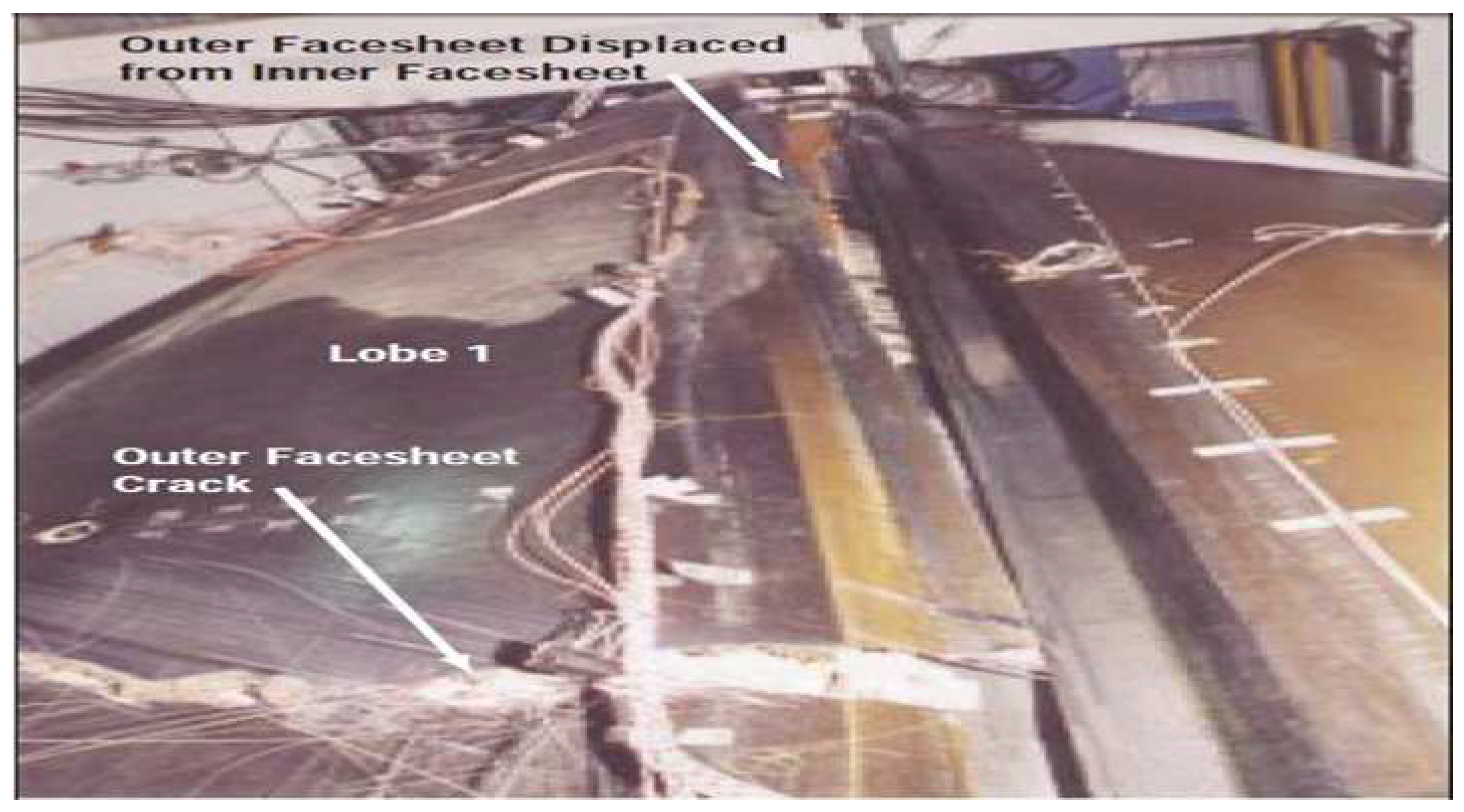
10. Challenges and Future Directions
The materials used in the space shuttle faced various challenges, including the need for high- performance materials that could withstand the harsh space environment, such as extreme tem- peratures, vacuum, radiation, micrometeoroid impacts, and space debris. The materials also had to meet stringent safety and reliability requirements to ensure the success and safety of human spaceflight missions. Additionally, the materials used in the space shuttle needed to be lightweight to minimize the overall mass of the spacecraft and reduce the amount of propellant needed for launch. Despite the significant advancements in materials science and engineering, there are still on- going challenges and opportunities for future research and development in materials for space applications. For instance, the development of advanced composites with enhanced mechanical properties, improved thermal stability, and reduced outgassing for better performance in space environments. Research is also ongoing in the area of thermal protection materials, with a focus on developing lightweight, high-temperature resistant materials that can withstand the extreme heat of re-entry while minimizing weight and thickness. Another area of research is in the use of nanomaterials, such as carbon nanotubes and graphene, which have unique properties that could offer significant advantages in space applications, including improved strength, thermal conductivity, and radiation resistance. Additionally, research is ongoing in the use of additive manufacturing, or 3D printing, to fabricate complex and lightweight structures with tailored properties for space applications. Furthermore, the development of sustainable and environmen- tally friendly materials for space applications is gaining attention, as sustainability becomes a crucial aspect of space exploration. The use of recyclable, biodegradable, and renewable ma- terials could reduce the environmental impact of space missions and contribute to long-term sustainability in space exploration.
11. Conclusion
In conclusion, the significance of advanced insulation techniques and materials in the optimal functioning of the space shuttle within challenging environments cannot be overstated. The meticulous selection and design of materials, such as reinforced carbon-carbon (RCC) and ceramic tiles comprising the Thermal Protection System (TPS), play a pivotal role in safeguarding the spacecraft from extreme temperatures, particularly during re-entry. The collective effort of insulation blankets, cryogenic insulation, structural insulation, and active thermal control systems contributes to maintaining the requisite temperature range for diverse spacecraft components. The proper application of insulation materials is fundamental to ensuring the safety, reliability, and overall performance of the space shuttle. As we look ahead, continuous research and development in insulation materials and techniques remain imperative for the advancement of spacecraft designs. The ongoing challenges and opportunities in materials for space applications underscore the need for exploration into innovative realms, including the evolution of composites, nanomaterials, additive manufacturing, and sustainability. Embracing these avenues will not only address current challenges but also pave the way for enhanced capabilities and resilience in future space exploration endeavors
References
- Garg, A. Pulsatile pressure enhanced rapid water transport through flexible graphene nano/Angstrom-size channels: A continuum modelling approach using the micro-structure of nanoconfined water. New Journal of Physics 2023, 25. [Google Scholar] [CrossRef]
- Garg, A. Modelling of enhanced water flow in deformable carbon nanotubes using a linear pressure-diameter relationship. ChemRxiv-Nanoscience 2023, 13. [Google Scholar] [CrossRef]
- Garg, A.; Prasad, P. Wall-slip effects on the yield-stress fluid flows in the rigid and deformable channel. ChemRxiv-Polymer Science, 2023; 1–30. [Google Scholar] [CrossRef]
- Garg, A. Enhanced flow in deformable carbon nanotubes. ChemRxiv- Nanoscience, 2023; 1–17. [Google Scholar] [CrossRef]
- Abd El-Hameed, A.M.; Abdel-Aziz, Y. Aluminium Alloys in Space Applications: A Short Report. Journal of Advanced Research in Applied Sciences and Engineering Technology 2021, 22, 1–7. [Google Scholar] [CrossRef]
- Olivas, J.; Wright, M.; Christoffersen, R.; Cone, D.; McDanels, S. Crystallographic oxide phase identification of char deposits obtained from space shuttle Columbia window debris. Acta Astronautica 2010, 67, 553–560. [Google Scholar] [CrossRef]
- Ochoa, N.U.; Smith, A.; Cone, D.; Stafford, S.; Olivas, J. Investigation of material response to atmospheric re-entry exposure of sub-structural Ti-6Al-4V components recovered from Space Shuttle Columbia. Journal of Space Safety Engineering 2021, 8, 113–120. [Google Scholar] [CrossRef]
- Lyle, K.H.; Fasanella, E.L. Permanent set of the space shuttle thermal protection system reinforced carbon–carbon material. Composites Part A: Applied Science and Manufacturing 2009, 40, 702–708. [Google Scholar] [CrossRef]
- Alpert, B.K.; Johnson, B.J. Extravehicular activity framework for exploration-2019. International Conference on Environmental Systems, 2019, number JSC-E-DAA-TN70005.
- Degtyarev, A.; Lobanov, L.; Kushnar’ov, A.; Baranov, I.Y.; Volkov, V.; Perepichay, A.; Korotenko, V.; Volkova, O.; Osinovyy, G.; Lysenko, Y.A.; others. On possibilities for development of the common-sense concept of habitats beyond the Earth. Acta Astronautica 2020, 170, 487–498. [Google Scholar] [CrossRef]
- Naser, M.Z.; Chehab, A.I. Materials and design concepts for space-resilient structures. Progress in Aerospace Sciences 2018, 98, 74–90. [Google Scholar] [CrossRef]
- Garg, A. Flight Dynamics. GATE Aerospace Forum Educational Services, 2015.
- Garg, A. Aerodynamics. GATE Aerospace Forum Educational Services, 2015.
- Garg, A. Aircraft Propulsion. GATE Aerospace Forum Educational Services, 2015.
- Vishal, G.; Garg, A.; Sarkar, J.; Pattanayek, S.K. The channel flow of a real shear thickening fluid using the Lattice Boltzmann Simulation and the Theoretical Model. ChemRxiv- Chemical Engineering and Industrial Chemistry, 2023; 1–26. [Google Scholar] [CrossRef]
- Vishal, G.; Garg, A.; Sarkar, J.; Pattanayek, S.K. Real Shear Thickening Fluid (STF) Flow in Converging-Diverging Channels: Analytical and Lattice Boltzmann Study. ChemRxiv- Chemical Engineering and Industrial Chemistry, 2023; 1–29. [Google Scholar] [CrossRef]
- Vishal, G.; Garg, A.; Sarkar, J.; Pattanayek, S.K. Modelling of Real Shear Thickening Fluid (STF) Flow around a Circular Cylinder within a Channel using the Lattice Boltzmann Method. ChemRxiv- Chemical Engineering and Industrial Chemistry, 2024; 1–19. [Google Scholar] [CrossRef]
- Tavassoli, A. Metallic materials for the space shuttle. The Aeronautical Journal 1972, 76, 152–156. [Google Scholar] [CrossRef]
- Finckenor, M.M., Document ID 20160013391. In Aerospace Materials and Applications; American Institute of Aeronautics and Astronautics, 2018. NASA Marshall Space Flight Center Huntsville, AL, United States. [CrossRef]
- Zhang, X.; Chen, Y.; Hu, J. Recent advances in the development of aerospace materials. Progress in Aerospace Sciences 2018, 97, 22–34. [Google Scholar] [CrossRef]
- Sivolella, D. Space Shuttle in Uniform; Springer, 2017. [Google Scholar]
- Basheer, A.A. Advances in the smart materials applications in the aerospace industries. Aircraft Engineering and Aerospace Technology 2020, 92, 1027–1035. [Google Scholar] [CrossRef]
- Council, N.R.; others. Materials Needs and R&D Strategy for Future Military Aerospace Propulsion Systems; National Academies Press, 2011.
- Rajput, A.; Upma.; Shukla, S.K.; Thakur, N.; Debnath, A.; Mangla, B. Advanced Polymeric Materials for Aerospace Applications. Aerospace Polymeric Materials 2022, 117–136. [Google Scholar]
- Vaz, R.F.; Garfias, A.; Albaladejo, V.; Sanchez, J.; Cano, I.G. A Review of Advances in Cold Spray Additive Manufacturing. Coatings 2023, 13, 267. [Google Scholar] [CrossRef]
- Franz, G.; Hassan, M.H. Structural Health Monitoring of Laminated Materials for Aerospace Application. In Structural Integrity and Monitoring for Composite Materials; Springer, 2023; pp. 1–26. [Google Scholar]
- Norkhairunnisa, M.; Chai Hua, T.; Sapuan, S.; Ilyas, R. Evolution of aerospace composite materials. In Advanced Composites in Aerospace Engineering Applications; Springer, 2022; pp. 367–385. [Google Scholar]
- Golfman, Y.; Sudbury, M. Spray Deposition of Aerogels as a Thermal Insulation for the Space Shuttle Fuel Tanks. An International Journal of Processing, Science, Characterization and Application of Advanced Materials, 2007; 42. [Google Scholar]
- Tanzilli, R.A. Development of an External Ceramic Insula-tion for the Space Shuttle Orbiter. NASA CR-112257,-National Aeronautics and Space Administration, 1973. [Google Scholar]
- Rahman, M.; Shaw, J.; Roesel, M.; William, B.; Willis, J.; Salekeen, S.; Ahmed, M. Finite Element Analysis of Silica Aerogel to Be Used in High Temperature Insulation Tiles for next Generation Space Tiles 2015.
- Silver, F. Biomaterials, Medical Devices and Tissue Engineering: An Integrated Approach: An Integrated Approach; Springer Science & Business Media, 1993. [Google Scholar]
- Burr, K. Reuseable lightweight modular multi-layer insulation for space shuttle. Technical report, 1973.
- Barber, J. Cryogenic insulation technology review for the space shuttle. SPACE TRANSPORTATION SYSTEM TECHNOL. SYMP., VOL. 5 JUL. 1970, 1970.
- Florence, D.; Gorsuch, P.; Tanzilli, R. Reusable external insulation TPS for the space shuttle. NASA. MANNED SPACECRAFT CENTER NASA SPACE SHUTTLE TECHNOL. CONF., VOL. 2 APR. 1971, 1971.
- Forsberg, K. Description of the manufacturing challenges in producing the high-temperature reusable surface insulation for the thermal protection system of the Space Shuttle. Congres International Aeronautique, 1979, number AAAF PAPER NT 79-42.
- Fleck, R.; Lehman, J. Mechanical Attachment of Reusable Surface Insulation to Space Shuttle Primary Structure. NASA. Ames Res. Center Symp. on Reusable Surface Insulation for Space Shuttle, Vol. 3, 1973.
- Ganpatye, A.; Kinra, V. Fracture toughness of space shuttle external tank insulation foam. 47th AIAA/ASME/ASCE/AHS/ASC Structures, Structural Dynamics, and Materials Conference 14th AIAA/ASME/AHS Adaptive Structures Conference 7th, 2006, p. 2020.
- Brazel, J.; Tye, R. Thermal characterization of reusable external insulation for the space shuttle. Technical report, 1972.
- McWhorter, B.; Ewing, M.; Albrechtsen, K.; Noble, T.; Longaker, M. Real-time measurements of aft dome insulation erosion on space shuttle reusable solid rocket motor. 40th AIAA/ASME/SAE/ASEE Joint Propulsion Conference and Exhibit, 2004, p. 3896.
- Finckenor, M.M. Materials for Spacecraft.
- Sharma, V.; Garg, A. Numerical Investigation of Effects of Compound Angle and Length to Diameter Ratio on Adiabatic Film Cooling Effectiveness. CoRR, 2014; abs/1405.0560. [Google Scholar]
- Chandrashekar, P.; Garg, A. Vertex-centroid finite volume scheme on tetrahedral grids for conservation laws. Computers & Mathematics with Applications 2013, 65, 58–74. [Google Scholar]
- Snapp, C. Evaluation of Space Shuttle Tile Subnominal Bonds 2006.
- Orbiter Thermal Protection System. NASA’s Kennedy Space Center Public Affairs Office, 2006. Archived from the original (PDF) on June 10, 2011. Retrieved June 7, 2011.
- Lardas, M. Space Shuttle Launch System 1972–2004; Bloomsbury Publishing, 2012. [Google Scholar]
- NASA. Advanced Flexible Reusable Surface Insulation Blankets. April 7, 2002, 2001. Archived from the original on February 10, 2001. Retrieved June 7, 2011.
- NASA. STS-41D Press Kit. August 1984. Archived from the original (PDF) on March 15, 2013. Retrieved July 12, 2013.
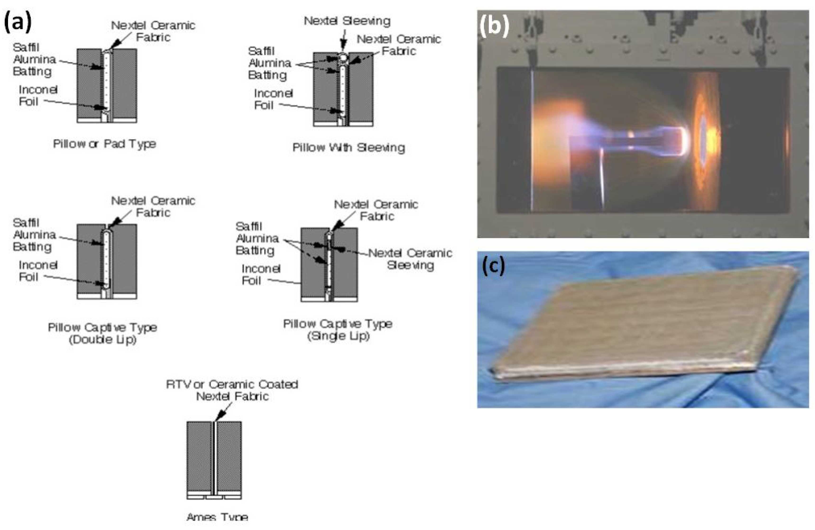
Disclaimer/Publisher’s Note: The statements, opinions and data contained in all publications are solely those of the individual author(s) and contributor(s) and not of MDPI and/or the editor(s). MDPI and/or the editor(s) disclaim responsibility for any injury to people or property resulting from any ideas, methods, instructions or products referred to in the content. |
© 2024 by the authors. Licensee MDPI, Basel, Switzerland. This article is an open access article distributed under the terms and conditions of the Creative Commons Attribution (CC BY) license (https://creativecommons.org/licenses/by/4.0/).
Copyright: This open access article is published under a Creative Commons CC BY 4.0 license, which permit the free download, distribution, and reuse, provided that the author and preprint are cited in any reuse.


