
Submitted:
04 February 2024
Posted:
05 February 2024
You are already at the latest version
Abstract
The aim of this study is to investigate transient dynamic flow characteristics of the fluid flow through 5-way electric coolant valve (PCCV : Penta-Control Coolant Valve). To achieve this goal, the present paper attempts the three-dimensional dynamic simulation of the fluid flow through the valve using a commercial CFD solver with moving mesh technique to consider flow inertia and dynamic flow in the opening and closing stages of the ball valve rotating motion. Firstly, dynamic flow characteristics and the thermal mixing inside the PCCV ball valve during the opening and closing stage was analyzed. It is found that the discrepancies between dynamic and steady state simulation is remarkable when fluxes with different levels of enthalpy and momentum flow into the PCCV leads to strong flow interference and flow inertia, while the discrepancies are relatively small at low rotation speed and weak flow interference. Then, the effect of dynamic flow characteristics of the valve on dynamic thermal mixing characteristics at two different ball valve rotational speeds and rotational directions were investigated. It was found that the dynamic flow and thermal mixing characteristics inside the PCCV are greatly affected by the rotation speed, rotation direction, and degree of flow interference between fluxes. It is helpful for the design of the better coolant control strategies and the improvement of the FCEV thermal management system.
Keywords:
5-way electric coolant control valve (PCCV : Penta-Control Coolant Valve)
; Fuel cell vehicle(FCEV)
; Thermal management system
; Computational fluid dynamics
; Moving grids technique
; Cooling circuit
; thermal mixing
; flow inertia
; dynamic flow chatacteristics
1. Introduction
While the development of eco-friendly vehicles is emerging as a great alternative to solving global warming and future depletion of fossil fuels, fuel cell vehicles are being considered as the final development stage for eco-friendly vehicles. Fuel cell vehicles are equipped with a fuel cell powertrain instead of a conventional gasoline/diesel engine, and major components include a fuel cell stack, driver system, electric power system, and control system. Among these, the operation system is an essential system for stack operation and consists of a thermal management system, an air supply system, and a hydrogen supply system [1,2]. The thermal management system(TMS) includes a water pump that circulates coolant, a three-way valve that determines the flow path according to the coolant temperature, a coolant ion filter to maintain coolant electrical conductivity, an indoor air conditioner, a cooling module, and a COD(Cathode Oxygen depletion) heater to improve stack cold start and durability.
The coolant temperature conditions in fuel cell vehicles are different, with stack cooling below 80℃ and electric drive cooling below 65℃, so each cooling system is separated. Compared to the coolant temperature condition of a conventional internal combustion engine of below about 120℃, the heat generation amount that is reaction by-product is lower than that of the existing internal combustion engine. This leads to increasing the size of the radiator.
For fuel cell vehicles, power performance such as rated output of the electric drive system, maximum vehicle speed, and hill climbing ability is determined by cooling performance, and the lifespan of the inverter's internal capacitor can also be determined. Therefore, distribution of cooling flow rate to each component included in the cooling system and control of coolant temperature are very important design technologies in the design of a fuel cell vehicle. In this context, coolant control ball valve, which is installed in the coolant circuit of FCEV is one of the most important coolant control devices in fuel cell vehicle, which allows accurate control of the flow rate and direction of coolant [3].
Previously, the multi-way valve commonly used to control coolant flow rate and direction in the cooling circuit of a fuel cell vehicle was a 3-way electrical coolant valve [4] or thermostat [5]. Figure 1 shows an example of a cooling circuit for a fuel cell vehicle. As shown in the figure, When the coolant temperature is low, the thermal management system loop bypasses the radiator, and when the coolant temperature is high, it cools through the radiator. In addition, coolant always flows through the branch loop that passes through the air conditioning heater and ion filter, and is designed to heat the inside passenger compartment and maintain electrical conductivity of the coolant.
While an electric water pump or a thermostat can control only the entire coolant circulation or only the coolant flow through a specific flow path, an electric coolant flow control valve (3-way valve) which has one inlet and two outlets can control the coolant flows in multiple paths of cooling circuit with a single unit. Since the electric coolant valve interconnects stack water jacket and coolant flow paths for multiple heat exchangers such as radiator, air conditioning heater, and COD heater, the valve will be able to open up or shut off coolant flow to the individual heat exchanging components, corresponding to vehicle’s operating condition. Furthermore, the valve can control the amount of flow to each component, which enables balances distribution of the coolant flow between the heat source and sink components for effective thermal management [6]. The coolant flow modulation is carried out by controlling ball valve position in coolant control valve with using an electric motor attached valve assembly.
The cooling circuit of the early TMS, as shown in Figure 1, had the problem of a sharp decrease in fuel efficiency due to high power consumption in the cold start period. Therefore, in order to improve fuel efficiency, TMS with a COD heater was introduced, but problems with reduced fuel efficiency during starting and stopping and durability of the stack and TMS still remain.
To compensate for these shortcomings, more precise control of coolant flow rate became necessary, and as a result, an increase in the flow path became inevitable. In addition, it has become urgent to develop new products that can reduce the unit cost of existing systems, make them lighter, and overcome space limitations. In particular, the thermal management system of a high-performance 100kW fuel cell operates according to a control strategy for each individual component, which makes it difficult to maximize the performance and lifespan of the fuel cell. To solve this, hardware integration of the thermal management system that operates for each individual component is required. In addition, modularization and an integrated module control strategy in software are also needed. Therefore, it was necessary to develop technology to secure market competitiveness through weight reduction and volume reduction through the development of a product that integrated one 3-way valve and one stack outlet manifold per vehicle in existing FCEVs into one structure. As shown in Figure 2, 5-way electric coolant control valve has been developed to achieve the above-mentioned solutions in this study.
As explained above, the electrical coolant valve is a key component in the TMM as it modulates the amount of coolant flow to individual components in cooling system such as stack, heater core, COD heater and radiator. Therefore, optimizing the control strategy of the electric coolant control valve which controls the electric valve’s position under various vehicle’s operating conditions is a very important design factor. However, system-level control logic optimization using actual vehicles has limitations because it requires a lot of cost and time [7]. Above all, the optimizing control logics of electric coolant valve based on an actual vehicle has the disadvantage of not being able to optimize the control algorithm in the early stages of vehicle design.
Therefore, in very recent, attention has turned to optimizing thermal management system and corresponding control strategies using integrated one-dimensional thermal management simulation model coupled with thermal-hydraulic model, vehicle model and controller model with understanding that these could offer a significant means to achieve improved the vehicle’s powertrain efficiency, fuel economy and occupant’s thermal comfort [8,9,10,11]. These previous literatures focused on various integrated thermal management system model with different control strategies based on fuel cell vehicles which considers the cooling of the driving system, fuel cell stack, battery and stack.
In most previous studies, the flow control valves such as the mechanical thermostat, electric thermostat, and 3-way electric coolant control valve that control the coolant flow rate and direction are modeled by several valves with junctions. The valve opening area was based on the function to control the flow to different components. However, the model was built based on the assumption that the volume of junction is small and incoming gases are well-mixed. Additionally, flow coefficients for each valve opening area that controls flow rate are calculated in steady state condition.
However, the 5-way electric coolant control valve, which is the subject of research, has four inlets and one outlet, so the volume is large and complex turbulent flow exists inside. Additionally, in order to quickly respond to various operating conditions, the ball valve rotates at a very high speed, so the valve opens and closes very quickly. Therefore, it is difficult to describe the movement of this 5-way coolant control valve using conventional modeling techniques based on steady-state and well-mixed conditions. Ultimately, if an integrated thermal management simulation model is constructed by modeling with PCCV based on conventional modeling techniques, prediction accuracy will be deteriorated.
Therefore, for the design and control of 5-way electric coolant control valve, it is not only necessary to understand the flow characteristics inside the valve, but also need to consider some complex flows (such as vortex, turbulence dissipation, and backflow) caused by fluid resistance during the spool opening process. However, to achieve this goal, there is a difficulty in considering the fast rotation of the valve, which is the operating condition of the 5-way valve. Accordingly, 3D dynamic flow characteristics research that simulates the rotation of a 3D ball valve has not been conducted due to obstacles such as high complexity, numerical instability, and high computational time-consuming.
Until now, most of the previous literature on internal flow characteristics considering the movement of the valve was geometrically simple and the movement of the valve was also simple due to the difficulties mentioned above [12,13]. Recently, a numerical model based on the moving grid technology is carried out to study the effect of spool rotating speed on the interna flow characteristics of the cryogenic ball valve with one inlet and outlet [14].
In this study, in order to consider the dynamic inertia effect caused by ball valve rotation, the rotation of the ball valve, which is the internal rotating body of a 5-way coolant control valve, was modeled three-dimensionally using the moving grid method. Using the model developed in this study, the dynamic behavior characteristics of the internal flow of the valve with respect to the rotational speed of the ball valve were studied. Dynamic flow characteristics has been quantitatively studied by comparing the flow rate and mixing temperature with the steady-state simulation results. The results of this study will be useful as basic design data for one-dimensional thermal hydraulic modeling of a 5-way valve to be applied to future integrated thermal management system simulation.
2. Problem descriptions
The geometrical and physical modeling involved in 5-way electric coolant control valve are complex and requires moving mesh approaches to account rotating valve movement based on three-dimensional compressible fluid dynamics.
The PCCV is responsible for regulating coolant flow to the five components of the thermal management system (stack, COD heater, ion filter, radiator, and water pump) to control the fuel cell stack to maintain a constant temperature of 58℃ (±1℃).
The structure of the 5-way electric coolant control valve is shown in Figure 3, which mainly consists of the rotate valve, pipes to different component, housing, drive mechanism and electric circuit. The rotate valve is used to control the coolant flow based on the layout of the pipes to every component. The rotate of valve was driven by the motor through drive mechanism. One function of the electric circuit was providing the power to the motor. The other function was measuring the rotate angle for feedback.
Through the rotating motion of the PCCV's ball valve, the opening degree of the 5 five ports connected to the thermal management system components is controlled, thereby generating primary pressure loss (orifice effect).
Figure 3 shows the part names and detailed diagrams of the 5-way PCCV.
As shown in Figure 3, The rotate valve consists of three vertical layers and is connected to five ports. Therefore, a secondary loss (flow interaction loss) occurs in which the degree of opening and closing of the valve in each layer affects other layers. The flow streamlines shown in Figure 4 are when all ports of PCCV are partially open and are the results of the flow simulation of this study. Ultimately, depending on the complex geometry of rotate valve inside the PCCV, the turbulent streams flowing into the valve from each port interfere with each other, causing pressure loss and uneven enthalpy mixing due to turbulent viscous dissipation.
3. Numerical methods
To investigate the transient dynamic flow characteristics of PCCV and qantitatively studied the difference between dynamic and static flow characteristics, multiple CFD simulations of the flow were conducted using ANSYS Fluent [15] and Simerics MP+ [16]. The three-dimensional steady-state flow analysis was performed using ANSYS Fluent, and the transient dynamic flow simulation using the moving grid method was calculated using Simerics MP+.
In the following subsections, details of the simulation setup and results from the simulations are presented.
3.1. Computational grid
The grids system including the four inlet pipes, one outlet pipe, one rotate ball valve and one valve housing is shown in Figure 5. To allow relative motion between the internal rotate ball valve and housing of the PCCV, there are clearances of the order of few microns between the rotate ball valve and the valve housing. However, the sealing action between port gasket and the ball valve is assumed perfect in time with a consequent null, leakage flow in the gap between rotate ball valve and port inlet gasket. Therefore, the clearance is neglected in this study, and there is no computational domain of the clearance.
In addition, in order to make the flow of each inflow and outflow pipe fully developed condition, the length of the pipes is set as 15 times the diameter of the pipes.
Figure 5 shows Computer-Aided Design(CAD) surface data of PCCV and grids system of computational domains. The fluid domain of the PCCV is extracted from the CAD which is provided by the industrial partner INZI CONTORLS and the geometry is imported into CFD codes (Simerics-MP+ and ANSYS Fluent). The computational domains were discretized into meshes with structured and unstructured regions. As the flow conditions investigated in this work includes turbulent flow regimes, special attention was given to the mesh size near the walls. In particular, as the wall functions were used in the turbulence modelling, the dimensionless distance of the first grid point from the wall, y+ was ensured to be 30 ≤ y+≤100 [17]. In this study, three-dimensional grid for considered geometry comprises 57,096 nodes and 51,250 elements has been imported to flow solver.
3.2. Mathematical formulation for moving grid
To study the effects of ball valve rotating on the flow behavior inside PCCV, dynamic flow simulations were conducted using the commercial CFD software Simerics-MP+[16]. This software is preferred by the authors over ANSYS Fluent[15] for transient dynamic flow simulation with moving/sliding grids technique because of its superiority in terms of numerical stability and easy-to-converging[18,19]. Simerics software has advanced morphing capability and, hence, increase computational efficiency and stability.
For a better computational efficiency, the entire flow region was split into two sub-regions. One is the ball valve area that rotates with the central axis, and the other is the non-deforming sub-region inside the valve housing that includes four inlet ports and one outlet port. The movement of the rotating ball valve sub-region is controlled by moving mesh algorithm embedded in CFD commercial software Simerics-MP+. Each sliding/moving cell connects to the others through a common interface, which is updated at each time step because of cell deformation and movement. The grid is explicitly remeshed and changed the shape of solution domain during the whole working process to cooperate with the moving deforming boundary. The hexahedral structured grid and the moving mesh algorithm ensure the orthogonality of the deforming sub-domain while the orbiting scroll is rotating [16].
Governing equations for moving grids technique of CFD are the mathematical expressions that describe the conservation of mass, momentum, and energy in a fluid flow with moving boundaries or interfaces. The governing equations for 3-D compressible N-S equations can be referred in [14,17]. The standard formulation of the conservation of the variable for a volume V with moving boundaries is based on the Reynolds transport theorem, which relates the rate of change of a conserved quantity inside a control volume to the flux of that quantity across the control surface. The general form of the conservation of the variable for a volume V with moving boundaries is
Where ρ is the density, ϕ is the variable of interest, v is the fluid velocity, vs is the velocity of the control surface, n is the unit normal vector pointing outward from the control surface, and is the rate of production or destruction of ϕ per unit mass. Equation (1) can be applied to any conserved quantity, such as mass, momentum, or energy. The conservation of mass for a volume V with moving boundaries can be obtained by setting ϕ=1 and in the above equation, which gives:
This equation states that the rate of change of mass inside the control volume is equal to the net mass flux across the control surface. In the similar way, The conservation of linear momentum written in moving boundary description is given as,
where τ is the Reynold’s average viscous shear stress tensor, p is the pressure, and f is a body force which is neglected in this study. In this work, both turbulence and energy equations are considered. Further details concerned to moving grids technique and computational algorithm in software can be referred in [12,16].
turbulence and cavitation physical models are considered during the simulation.
The opening and closing speed of the PCCV is governed by setting the rotational speeds of the ball valve, and setting the rotational speed of the ball valve as 94 deg/s and 47 deg/s, respectively. By setting the rotation speed of the ball valve, the opening area of each port changes continuously and the inflow mass flow rate is controlled accordingly. In Figure 6, the opening area that changes as the ball valve rotates is shown as a percentage for each inlet port. This means that 100% is fully opened. The x-axis means the rotation angle. The angle, which the ball valve rotates clockwise from the closed position, is defined as the rotating angle of ball valve.
The rotation period of the ball valve was clockwise from 0° to 94°, and then counterclockwise from 0° to 94°, for a total of 188°, and the moving-grids method was used to simulate the rotation of the ball valve.
3.3. Initial & Boundary conditions
In this study, for stable transient dynamic calculation, steady-state analysis was performed with the condition of the ball valve at 0 degrees, and the result was used as the initial value in transient dynamic calculation.
In this study, the working fluid was considered to be a half-mixture of ethylene glycol and water, which density, thermal conductivity, specific heat and kinematic viscosity are 1,087 kg/m3, 0.37 W/mK, 3,285 J/kgK, 0.0038 kg/ms, respectively. As shown in Figure 3 and Figure 4, coolant streams cool the stack, COD heater, radiator, and ion-filter, respectively and flows into the PCCV through four inlet ports. Afterwards, the coolant flow flowing in from each cooling component is mixed inside the PCCV and then exits to the electric water pump through the outlet port.
Moving to the boundary conditions, pressure boundary conditions were applied at the inlet and mass flow rate condition was imposed at outlet of the domain (as shown in Figure 5). No slip boundary condition was employed on the walls. Boundary conditions were obtained from experimental data originated by a test bench campaign held at the department of integrated thermal management system of INZI CONTROLS. For the boundary conditions, the inlet pressures at four inlet ports are atmospheric pressure and two outlet mass flow rate conditions, 20 and 100 LPM(liter per minute) are considered. Inlet thermal boundaries at inlet ports from stack, COD heater, ion-filter and radiator are 75℃, 30℃, 30℃ and 65℃, respectively.
The steady-state calculation used the same boundary conditions as in the case of dynamic simulation, and the opening area at each port was imposed as shown in Figure 6 and the ball valve was not moving.
3.3. CFD solver & numerical implementation
CFD solvers used in this paper to perform the transient dynamic flow analysis of this PCCV are based on finite volume method and solve the conservation of mass and momentum equations along with turbulence and energy equations. As a finite volume method, the mesh of the entire fluid domain is discretized using high-quality structured and unstructured hexahedral cells.
The standard k-ε model and the RNG k-ε model are the most common and mature turbulence models, but there are many others that have different strengths and limitations depending on the flow problem. However, these two models have been available for more than a decade and have been widely demonstrated to provide good engineering results. The RNG k-epsilon model uses a modified value of Cϵ2 included in ε transport equation that is based on the Reynolds number and the turbulence intensity. Thereby, the RNG k- ε model has been shown to be more accurate than the standard k- ε model in a number of applications, including fast strain flows, swirling flows, separated flows, and flows with strong streamline curvature as the model constants are derived explicitly and contains a strain-dependent correction term [17]. Therefore, in this study, the RNG k-ε model [15,16,17] was selected as a turbulence model, considering its high accuracy and convergence stability optimized in the fast strain flow proposed by Yakhot and Orszag[17].
The iterative SIMPLE-like (Semi-Implicit Method for Pressure-Linked Equations) pressure–velocity coupling scheme is used to compute the pressure field. A second-order upwind scheme is used to discretize convective terms in momentum and energy equations. The criteria of convergence was the reduction of scaled residuals [17] of continuity, x, y and z momentum, k and ε equation and energy equations below 10-6.
The computer used to calculate the transient dynamic CFD model in this study was AMD Ryzen Threadripper 3960X 24-Core Processor 3.79 GHz. When the rotation speed of the ball valve was 94deg/s, the total calculation time was 5 hours and 8 minutes, and when the rotation speed of the ball valve was 47deg/s, it took 9 hours and 50 minutes.
4. Simulation results and flow analysis
In this study, we numerically studied the transient dynamic flow characteristics of a recently developed 5-way electric coolant control valve to quickly respond to changing operating conditions and precisely control coolant temperature. For this purpose, CFD analysis was performed considering the internal flow of the PCCV as three-dimensional compressible turbulent flow. In particular, the moving grids technique was adopted to accurately simulate the rapid rotation of the ball valve and the flow interference and non-uniform mixing characteristics of streams flowing in from the four inlet ports with different temperatures and flow rates. In order to qualitatively study the dynamic flow characteristics of this PCCV, the results of transient dynamic flow simulation were compared with the steady state case where each ball valve does not rotate.
4.1. Transient dynamic flow characteristics in rotating processes
The main purpose of this study is to investigate the mutual interference and dynamic inertia effect of the jet-like in-coming flow from each port due to the rotation of the ball valve. In Figure 7, Figure 8, Figure 9, Figure 10 and Figure 11, the flow rate flowing to PCCV at each inlet faces according to the rotation speed of the ball valve is shown. The results of transient dynamic simulation are compared to the steady state results.
In the case of the mass flow rate from the stack, as can be seen in Figure 7, under the condition of a high rotation speed of the ball valve (ω = 94), the average difference in flow rate between dynamic simulation and steady state simulation according to rotation is up to 19.3%, and under lower rotation speed (ω=47), there is a difference of up to 2.58%. Here, (+) means clockwise rotation and (-) indicates counterclockwise rotation.
As can be seen from the results, the direction of rotation has little effect on the dynamic mass flow profiles but the rotation speed impact greatly. In addition, it can be seen that many differences from the steady state results occur near the opening and closing timing. In particular, it can be seen that the difference between the steady state and dynamic analysis results increases as the closing time of the valve approaches (closing process). In case of a high rotation speed (ω=±94), the difference in flow rate between the steady state and dynamic simulation is up to 16%, and in case of a slower ball valve rotation speed (ω=±47), the difference in flow rate is up to 8%. In particular, the largest error can be found in ranging from 30 to 60 deg where the opening area of the stack port reaches its maximum.
In Figure 8, the mass flow rate flowing into the PCCV through the COD heater is compared with the rotation speed, rotation direction, and steady-state calculation results. A noteworthy feature is that the inflow rate is continuously decreasing in the 0-45 degree period, which is the fully open area. The reason for this is that the flow rate coming from the stack is gradually increasing in this section. As shown in Figure 5, this increase in flow from stack causes interference with the inflow from the COD heater, ultimately leading to a gradual decrease in inflow. Afterwards, as the inflow rate from stack and valve opening area of inlet port of COD heater gradually decrease, the inlet mass flow rate from the COD heater gradually decreases. As shown in Figure 7, it can be also seen that the rotation direction of the ball valve does not significantly affect the dynamic inlet mass flow profile, but the rotation speed does. Under conditions where the ball valve rotation speed was high (ω=94), the averaged difference from the steady-state flow rate due to ball valve rotation was up to 13.8%. Under conditions where the ball valve rotation speed was slower (ω=47), the difference in flow rate between steady-state calculation and dynamic simulation was as high as 34.5%. From these results, it can be seen that the temporal variation of mass flow rate flowing into the inlet port of the COD heater is more greatly affected by interference with the flow flowing in from the stack than by the dynamic inertia effect caused by ball valve rotation. Therefore, in the case of the PCCV with multiple inlet ports and a large internal volume, it is necessary to consider not only the rotational speed of the valve but also the mutual interference between jet-like flows flowing through each port into PCCV in order to predict the accurate inlet flow rate.
In Figure 9, the temporal variation of flow rate flowing from the ion-filter into the PCCV is compared with the steady-state calculation results for two kinds of rotation speeds and directions. It can be seen that the dynamic profile of inflow mass flow rate is very similar to that of the COD heater port. This is because the ion-filter port is open during the period when high-velocity jet-like streams flow from the COD heater port and stack port, resulting in severe interference with these flows. Therefore, even in the period when the inflow port from ion-filter is completely open, the flow rate from the stack port gradually increases, and the flow rate from the ion-filter port decreases. From these results, it can be observed that control of the inflow rate by controlling open area may become difficult due to interference with flows flowing in from other ports. Therefore, in the case of a multi-stage ball valve such as PCCV, the opening strategy can be designed effectively when it is designed to minimize mutual interference from each port.
The difference in mass flow rate between clockwise and counter-clockwise for two rotation speeds was up to 9% at ω = 94 and up to 6% at ω = 47. The average flow rate difference through the ion-filter port calculated from steady state and dynamic flow simulation is larger than that of the COD heater port and stack port. This is because, in the case of the temporal variation of mass flow rate of the ion-filter port, interference with flows flowing in from the stack port and COD heater port is more dominant than the dynamic inertia effect caused by the rotation of the ball valve.
Figure 9 shows temporal variations of mass flow rate from radiator as ball valve rotates for two different rotating speeds and directions and compared with steady state results. The flow rate of the inlet fluid flux from radiator is higher than that of other ports, and the flow interference effect is minimal as the port is opened during the period when other ports are in the closing process. Therefore, it is observed that as the opening area of the radiator port increases, the inlet flow rate increases linearly.
The difference in flow rate according to the rotation direction was up to 40% at ω = 94, which is not a large difference compared to other cases, but under the condition of a slower ball valve rotating speed (ω = 47), the difference in flow rate was up to 23%. The reason why the steady state and dynamic simulation results show a large difference compared to other cases when the rotation speed is low is because there is more flow interference with the inlet fluid flux of the three other ports. The difference between the results of steady-state analysis and dynamic flow simulation was 30-40% on average for ω = 94, and 33-38% for ω = 47, which was higher than other cases.
As can be seen from the results, since the momentum of the inlet fluid flux discharged when the rotating speed is low is weak, inlet fluid flux from radiator is severely interfered with the inlet fluid fluxes from other ports. Since steady-state calculations cannot take into account the interference effects of complex inlet fluid fluxes and changes in jet momentum flux due to temporal variation of opening area, the difference with steady-state analysis and dynamic flow simulation appear significantly.
4.2. Three-dimensional dynamic inertia flow analysis in the PCCV
In this section, the numerical results obtained from 3D dynamic flow simulation were analyzed to study the effect of ball valve rotation speed on PCCV internal flow characteristics and are compared to those of steady state solutions.
Figure 11 shows velocity distribution due to flow interaction of inlet fluxes from stack and COD heater for different rotation directions at rotation angle, 40 deg. As shown in Figure 11, it can be seen that the two inlet fluxes collide with each other and flow downward, and the flow rate from the COD heater is suppressed by the inlet flux with strong momentum flowing from the stack. This flow velocity distribution is also affected by the direction of rotation. When the ball valve rotates clockwise and reaches at 40 degree, the flow rate of flux flowing from the stack gradually increases at a rotation as shown in Figure 7, and when it rotates counterclockwise, reaching 40 degree right after full opening of port opening area, the flow inertia are bigger and stronger than that of clockwise. Therefore, a stronger jet-like stream from stack and weaker inlet flux from COD heater can be seen in the couter-clockwise direction. It is observed that the results of steady-state flow calculations that is not able to take into account the flow inertia of the inlet fluxes underestimate the velocity and flow momentum of both the inlet flux from COD heater and the inlet flux from stack.
Figure 12 shows the velocity distribution at the cross section just below the ion-filter port, where the jet-like flows coming in from three ports with fully open opening areas flow downstream with severe flow interference. A noteworthy feature is that when rotating direction is clockwise, the incoming fluxes from the ion-filter and COD heater, which have sufficient momentum, collide with the flux from the stack port and flow downstream. Therefore, it can be seen that the jet-like flows from ion-filter and COD heater is accelerating and moving downward as it hits the central wall of the plastic structure. However, in case of the counterclockwise direction, the flow inertia of the inlet flux flowing from the ion-filter and COD heater is not sufficiently developed, so it can be seen that it flows downward along the side wall of the plastic structure.
The flow interference of inlet fluxes from stack and COD heater at a rotation angle of 85 degrees is shown in Figure 13 for two rotation directions. It can be seen that the velocity distribution in this cross section is clearly different depending on the rotation direction of the ball valve. This is because, in the case of clockwise rotation, a very fast and strong flux from the stack port can be seen as the opening area of the stack port suddenly narrows, but in the case of counterclockwise rotation, the flow inertia of the flux from stack is not sufficiently developed and the inlet flux from COD heater is very weak. However, it can be confirmed that the steady-state calculation results, which cannot reflect this time history experienced by the unsteady flow, cannot describe the strong jet flow that appears due to an instantaneous change in the opening area. Therefore, it can be seen that reflecting the flow inertia effect due to the rapid change in opening area due to the rapid rotation of the ball valve is essential to accurately predict the flow distribution of the valve and the pressure drop of the flow that through the valve.
Figure 14 shows the velocity distribution of the flux from the radiator passing through the inside of the PCCV according to the rotation direction of the ball valve. From the results, the case of counterclockwise rotation, where the flow inertia of the flux from radiator port is greatly developed, is compared to the case of clockwise rotation, in which the flow inertia of the flux from the radiator port is not fully developed. Even the opening area is the same, there is inlet fluxes with different momentum and flow inertia according to rotation direction.
Temporal sequential iso-views of particle streak lines in PCCV are shown in Figure 15 to help understand the flow interference between fluxes flowing from each port. It can be clearly seen that the fluxes flowing into the COD heater and ion-filter port are strongly interfered with the jet-like stream discharged from the stack port, and consequently, as shown in Figure 8 and Figure 9, a linear relationship between the inflow flow rate and the opening area is not established. The flow interference with jet-like streams shown in Figure 15 may cause severe pressure drop along the flow direction due to the viscous thermal dissipation converting the kinetic energy of the turbulent eddies into heat due to the viscous friction. As the rotation progresses elapses, the flow rate of fluxes passing through the remaining ports except the radiator decreases, so the flux passing through the radiator port flows to the electric water pump without significant interference with other fluxes.
Figure 16 shows the velocity pulsation profile at 3 mm inside the PCCV from the open face of the ball valve connected to each port. Here, case 1 indicates a rotation speed of 94deg/s, and case 2 indicates a rotation speed of 47deg/s. As explained above, it can be confirmed that very complex velocity pulsation profiles exist due to interference between jet-like streams with different momentum and flow inertia discharged from each port. The x-axis of the graphs is represented by accumulated rotation angles to easily display the complex pulsating velocity profile. That is, the clockwise rotation range is from 0 to 94 degrees, and subsequently the counterclockwise rotation range is from 95 to 188 degrees. First, the characteristics of the velocity pulsating profile inside the inlet of the stack port, which has the highest flow inertia among the fluxes of the three other inlet ports, are in sync with the opening area profile as shown in Figure 6 because there is little interference with fluxes from other ports. In other words, it can be seen that a peak velocity profile is formed in the area of 40-60 and 40-60 and 134-154 degrees of rotation angle, which is near the maximum of the opening area. On the other hand, in the case of COD heater ports and ion-filter ports, where the momentum and flow inertia of the incoming flux are relatively weak, they are not synchronized with the opening area profile due to severe flow interference with the flux from stack with strong flow inertia and momentum. As shown in Figure 16b, the peak area in the velocity pulsation profile of the COD-heater port occurs in the period when the streamwise momentum and flow rate of the flux from stack port are reduced. Moreover, in the case of flux from ion-filter, which has the smallest flow inertia, the inflow velocity decreases sharply even in the fully open section of 0-40 degrees. This is because the momentum of the flux from stack port increases steeply during this period, resulting in hindering incoming flux from ion-filter port. In case of radiator port, The inflow velocity increases rapidly and reaches its maximum in the rotation angle range of 60-90 degrees, where the opening area rapidly increases. The inflow velocity increases rapidly and reaches its maximum in the rotation angle range of 60-90 degrees, where the opening area rapidly increases. This is because the distance from the radiator inlet port to the outlet port of the electric water pump is short and the flow rate and flow inertia of the flux are large, so flow interference with other fluxes is small.
4.4. Transient dynamic thermal mixing characteristics in the PCCV
As explained above, the electrical coolant valve is a key component in the TMM as it modulates the amount of coolant flow to individual components and thereby coolant temperature in cooling system. Therefore, many previous literatures [3,4,5,6,7,8] developed one-dimensional integrated one-dimensional thermal management simulation model coupled with thermal-hydraulic model to predict coolant temperature at several locations for coolant control strategy. However, in the case of the PCCV, which is the subject of this study, is the control valve with a large internal volume and different levels of enthalpy streams from several inlet pipes, it is difficult to predict accurately the outlet temperature based on simple calculation by weighted-averaged inlet enthalpies as in Equation (4) below, which has been used in many previous one-dimensional models.
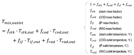
Therefore, in this study, in order to analyze the effect of dynamic inertia flow characteristics on thermal mixing inside the PCCV and quantify the error, the outlet temperature by dynamic flow simulation using moving-grids was compared with the results from steady state simulation and equation (4).
In Figure 17, Figure 18, Figure 19 and Figure 20, the temperature distribution inside the PCCV at ω=±94 deg/s at various angles is shown in cross sections at several different axial locations. Summarizing the results, it can be noted that even at the same rotation angle, the temperature distribution is clearly different according to the rotation direction of the valve. This is because the flow inertia and momentum of each flux are different because the time history of boundary conditions experienced by each inlet flux is different. This is due to the fact that there are multiple inlet ports and the enthalpy, momentum, and flow inertia of the inlet fluxes flowing from them are different. Therefore, in the case of PCCV, very non-uniform thermal mixing occurs due to flow interference, so it is difficult to accurately predict the mixing temperature at outlet using a simple average method such as the equation (4).
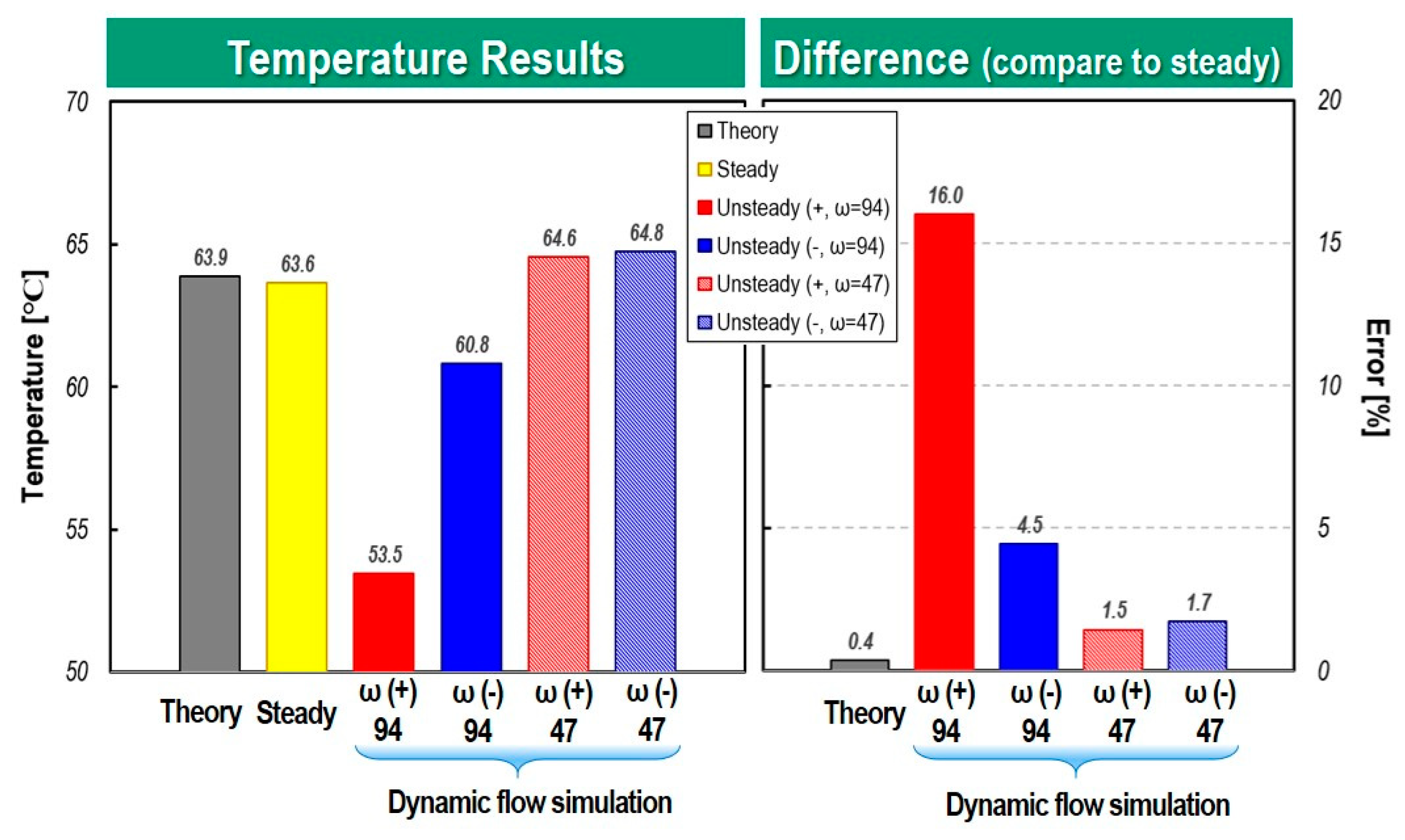
Figure 21 and Figure 22 quantitatively compare the mixing temperatures according to each analysis method. In the case of a rotation angle of 40 degrees, where there is severe interference between the fluxes discharged from the COD-heater and the stack port, and particularly in the case of a fast rotation speed of ω = ±94 deg/s, the temperature difference according to the rotation direction is 51% and in case of ω = ±47 deg/, it was 35%. From the results, it can be clearly seen that when the rotation speed of the ball valve is high, the temperature mixing inside the PCCV is very non-uniform due to different flow inertia and flow interference between the incoming fluxes. The difference between the mixing temperature calculated from the steady-state analysis and equation (4) was only 2.8%. However, steady state model with no consideration of rotation speed and direction shows maximum 51% difference of the mixing temperature compared to that of dynamic flow simulation. Therefore, it can be deduced that if a cooling circuit using a multi-way coolant control valve such as PCCV is modeled one-dimensionally, it is expected that many errors will occur in mixing temperature predictions and control logic optimization. As can be seen in Figure 22, in the case of a rotation angle of 85 degree with weaker flow interference, it is evident that the dynamic flow effect is reduced. But in the case of high rotation speed, the dynamic behavior effect is shown clearly.
5. Conclusions and remarks
In this study, three-dimensional thermo-fluid CFD model of the 5-way electric coolant control valve (PCCV) taking flow inertia and dynamic flow characteristics into account. To achieve this goal, moving-grids techniques to consider flow inertia and dynamic flow in the opening and closing stages of the ball valve rotating motion.
The simulation results demonstrate three-dimensional dynamic inertia flow has a great impact on flow distribution and thermal mixing in PCCV. In other words, as fluxes with different levels of enthalpy and momentum flow into the PCCV, their flow interference and inertia make dynamic flow characteristics flow and thermal mixing pattern that is completely different from the steady state solution. From the results of this study, it was found that the dynamic flow and thermal mixing characteristics inside the PCCV are greatly affected by the rotation speed, rotation direction, and degree of flow interference between fluxes.
This study can be used as a reference for one-dimensional hydraulic modeling of PCCV which can consider the effect of the flow inertia and flow interference and corresponding integral thermal management framework, and helps to achieve better coolant control strategies in the future.
Author Contributions
Conceptualization, S.-J. J., J.K. ; methodology, S.-J. J.; software, S.-J. J. and S.-J.M.; validation, S.-J.J.; formal analysis, S.-J.J., S.-J.M. and G.L.; investigation, S.-J.J..; resources, S.-J.J., J.K., S.-J.M and G.L.; data curation, S.-J.J. and J. K.; writing—original draft preparation, S.-J.J.; writing—review and editing, S.-J.J.; visualization, S.-J.J., S.-J.M.; supervision, S.-J.J.; project administration, S.-J.J. and S.-J.M.; funding acquisition, S.-J.J. and J.K. All authors have read and agreed to the published version of the manuscript.
Funding
This work was supported by the new industry entry business reorganization core technology development Project of the Korea Evaluation Institute of Industrial Technology, funded by the Korean government (Grant No. P0017348).
Data Availability Statement
Most of the data presented in this study are available on request from the corresponding author. Some data were obtained from a third party.
Conflicts of Interest
The authors declare no conflicts of interest.
References
- Sorensen, B. Hydrogen and fuel cells, Elsevier Academic Press, Massachusetts, USA, 2004; pp.210-218.
- Kim, H. K.; Baek, S. H.; Na, S. W.; Park, H.; Kim, D. J.; Han, D., Thermal management system of fuel cell vehicle. Patent Application Publication. U.S.A Patent No. 20170062846A1, 2017.
- Xu, J.; Zhang, C.; Fan, R.; Bao, H.; Wang, Yi, W.; Huang, S.; Chin, C. S.; Li, C. Modelling and control of vehicle integrated thermal management system of PEM fuel cell vehicle. Energy 2020, 199, 117495-117511. [CrossRef]
- Xu, J.; Zhang, Zhang, C.; Wan, Z.; Chen, X.; Chan, S. H.; Tu, Z.; Progress and perspectives of integrated thermal management systems in PEM fuel cell vehicles: A review. Renew Sust. Energ. Rev.2022, 155, 111908-111931.(3-way). [CrossRef]
- Jiang, H.; Xu, L.; Li, J. Q.; Hu, Z.; Ouyang, M. Design and control of thermal management system for the fuel cell vehicle in low-temperature environment. SAE Tech. pap. 2020, 2020-01-0851. [CrossRef]
- Pimpinella, L.; Mikulas, O.; Ko, M. S.; Bae, I. H.; Herceg, M.; Pekar, J.; Kim, Y. k.; Jung, Y. H. Advanced coolant temperature control study with integrated thermal management system valve. In Proceedings of IFAC, Online, www.sciencedirect.com 2021. [CrossRef]
- Lee, H.; Jeong, K.; Yoo, S.; Lee, B.; Kim, S. Control for electrical coolant valve in engine thermal management module. SAE Tech. pap. 2017. 2017-01-2204. [CrossRef]
- Yang, Q.; Zeng, T.; Zhang, C.; Zhou, W.; Xu, L.; Zhou, J.; Jiang, P.; Jiang, S. Modeling and simulation of vehicle integrated thermal management system for a fuel cell hybrid vehicle. Energy Convers. Manag. 2023, 278, 116745-116760. [CrossRef]
- Qu, Y.; Li, D.; Wang, R. Study on integrated thermal management system of hydrogen fuel cell vehicles based on heat pump air conditioning. J. Clean. Prod. 2023, 434, 139951-139966. [CrossRef]
- Hu, D.; Hou, W.; Xiang, C.; Lu, D.; Yang, Q.; Li, J.; Wang, J. Waste heat utilization performance verification of heat exchanger only thermal management system for fuel cell vehicle. J. Clean. Prod. 2023, 428, 139479-139491. [CrossRef]
- Chen, Y-M.; Lee, J.; Holmer, J.; Ha, J. Model predictive control for engine thermal management system. SAE Tech. pap. 2017, 2021-01-0225. [CrossRef]
- Srikanth, C.; Bhasker, C. Flow analysis in valve with moving grids through CFD techniques. Adv. Eng. Softw. 2009, 40, pp.120376-120386. [CrossRef]
- Liu, C.; Zhao, M.; Wang, W.; Li, J. 3D CFD simulation of a circulating fluidized bed with on-line adjustment of mechanical valve. Chem. Eng. Sci. 2015, 137, pp.646-655. [CrossRef]
- Lin, Z-h.; Li, J-y.; Jin, Z-j.; Qian, J-y. Fluid dynamic analysis of liquefied natural gas flow through a cryogenic ball valve in liquefied natural gas receiving stations. Energy 2021, 226, pp.120376-120386. [CrossRef]
- ANSYS™ Fluent, Release 19.1, 2021.
- Simerics-MP+, Simerics, ver. 5.2.15, 2020.
- Versteeg, H. K.; Malalasekera, W. An introduction to computational fluid dynamics. 2nd ed.; Harlow, England, 2007; pp.77-176.
- Lakshmanan, K.; Teccicini, F.; Gil, A. J.; Auricchio, F. A fault prognosis strategy for an external gear pump using Machine Learning algorithms and synthetic data generation methods. Appl. Math. Model. 2023, 123, pp.348-372. [CrossRef]
- Zheng, S.; Wei, M.; Zhou, Y.; Hu, C.; Song, P. Tangential leakage flow control with seal-grooves on the static scroll of a CO2 scroll compressor. Appl. Therm. Eng. 2022, 208, pp.118213-118226. [CrossRef]
- Yakhot, V.; Orszag, S. A.; Thangam, S.; Gatski, T. B.; Speziale, C. G. Development of turbulence models for shear flows by a double expansion technique. Phys. Fluids. A. 1992, 4, pp.1510-1520. [CrossRef]
Figure 1.
An example of a thermal management system for a fuel cell vehicle.
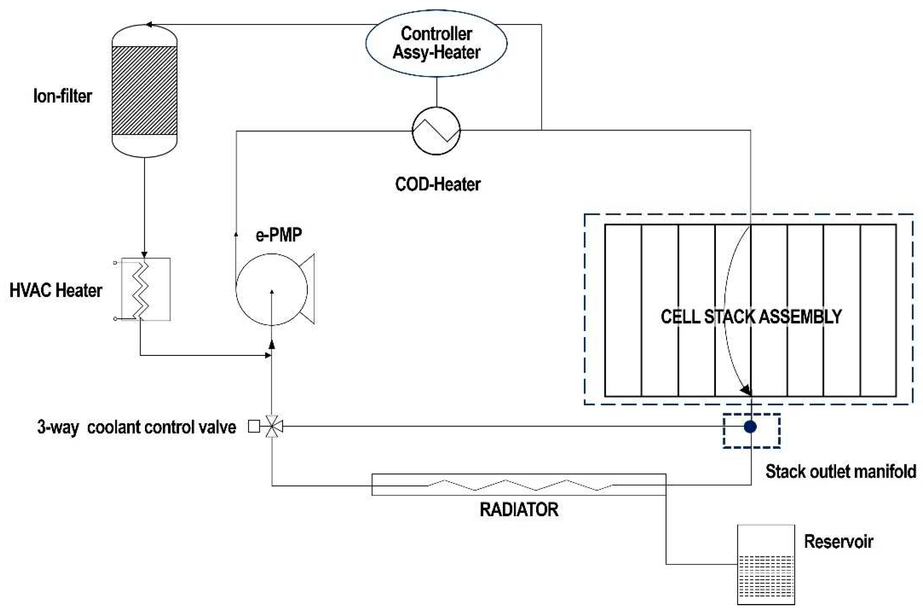
Figure 2.
Illustration of 5-way electric coolant control valve concept for an integrated module cooling strategy.
Figure 2.
Illustration of 5-way electric coolant control valve concept for an integrated module cooling strategy.
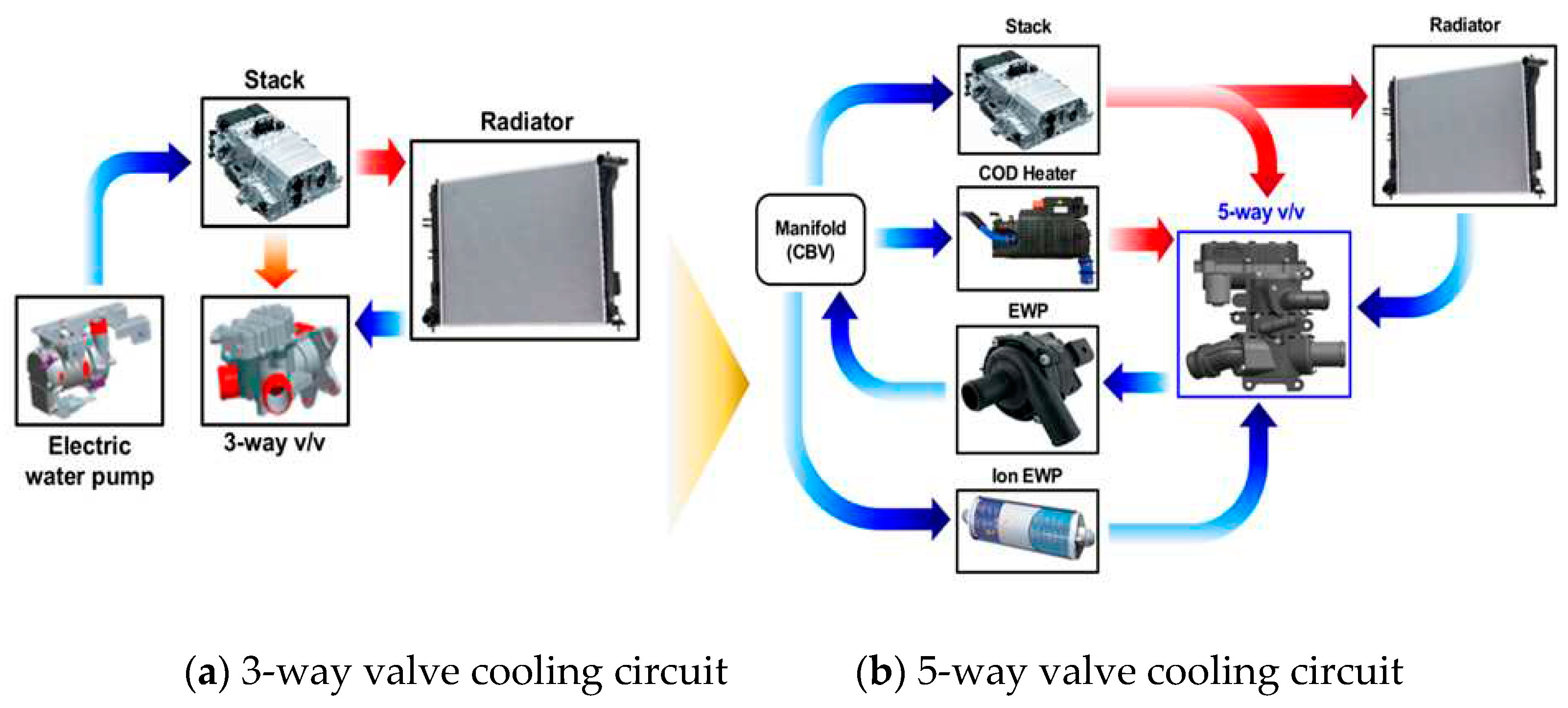
Figure 3.
Exploded view of 5-way electric coolant control valve.
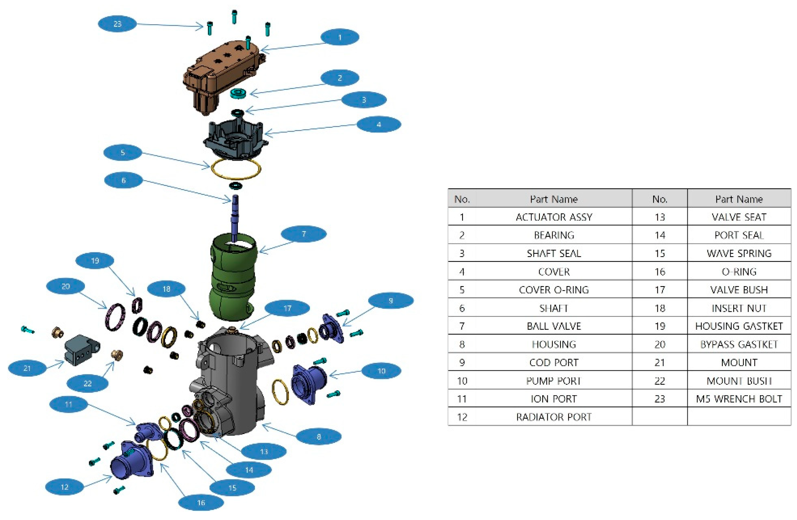
Figure 4.
Geometrical details of 5-way electric coolant control valve and internal flow paths.
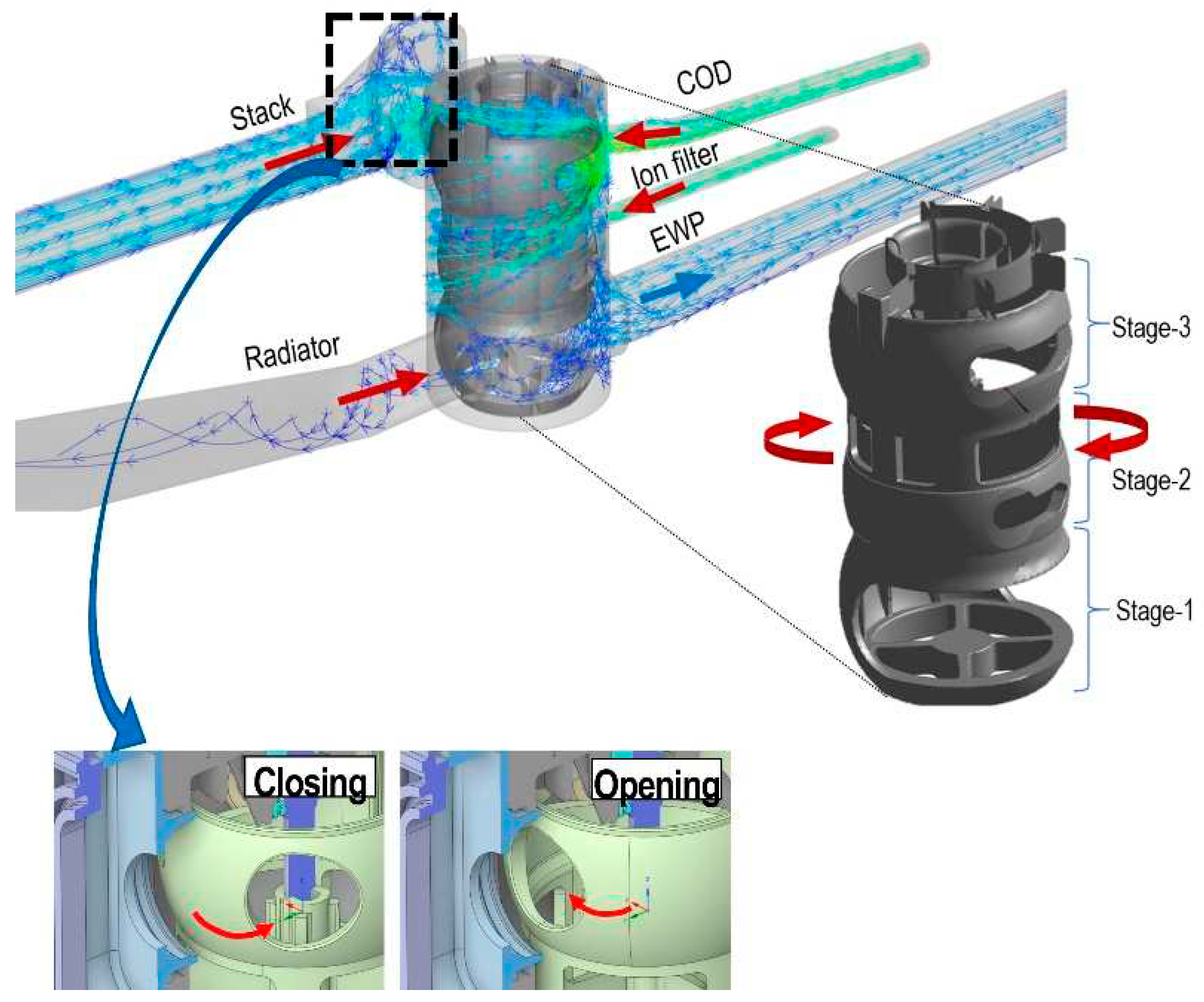
Figure 5.
CAD surface data and computational grids system of PCCV (a) CAD data (b) Grids system.
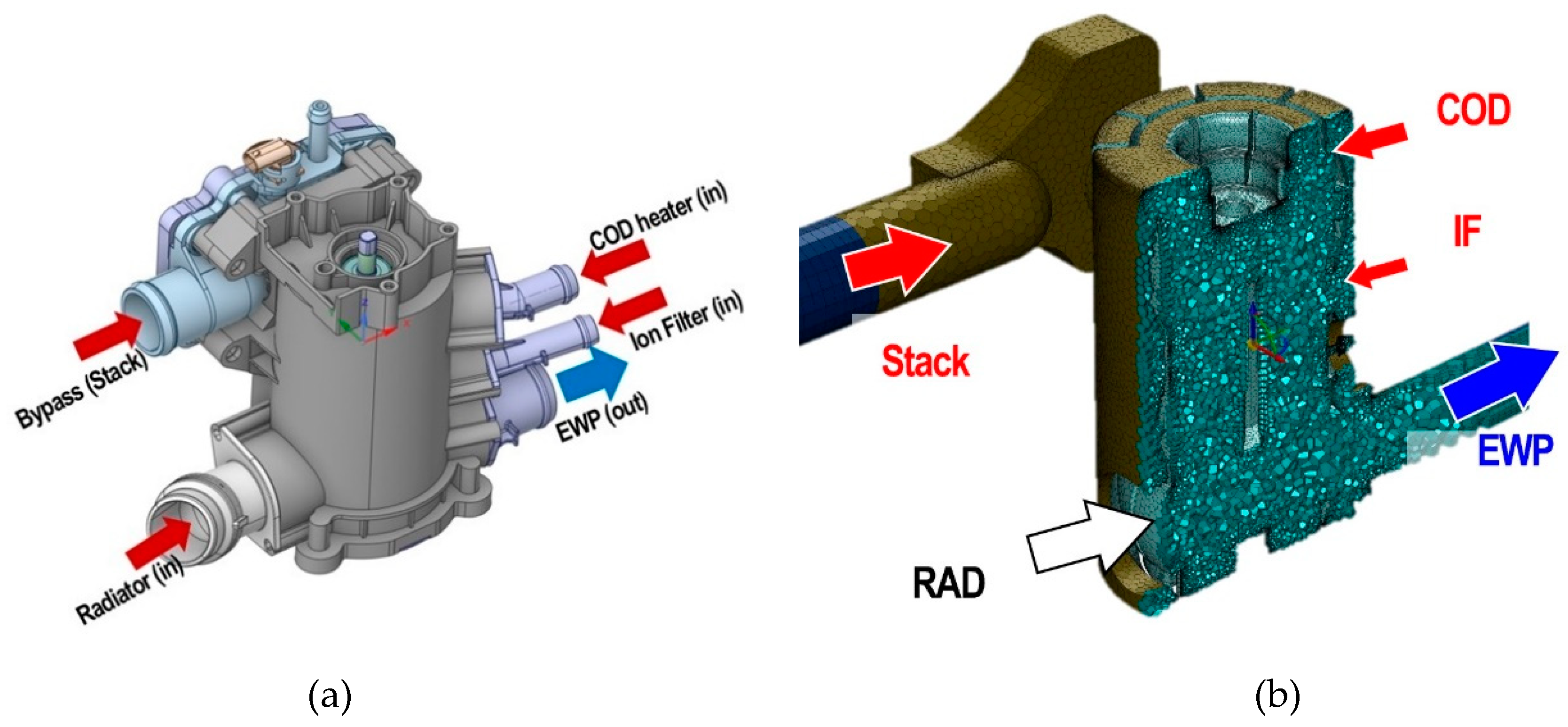
Figure 6.
Variable opening area of each port with respect to ball valve rotating angle(deg).
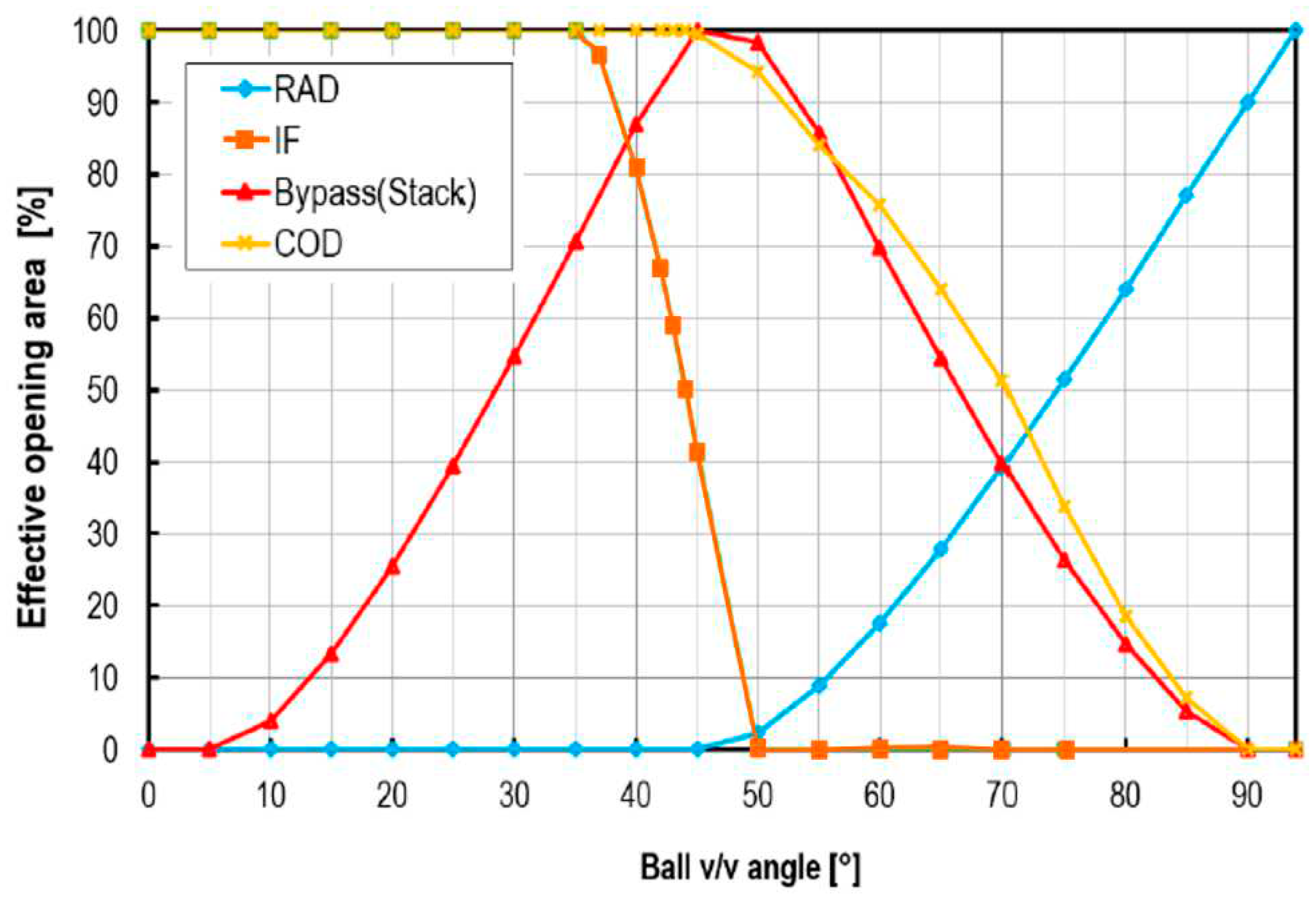
Figure 7.
Temporal variation of mass flow rate at inlet face of stack port for various rotation speeds and averaged discrepancies between transient dynamic flow analysis and steady state analysis.
Figure 7.
Temporal variation of mass flow rate at inlet face of stack port for various rotation speeds and averaged discrepancies between transient dynamic flow analysis and steady state analysis.
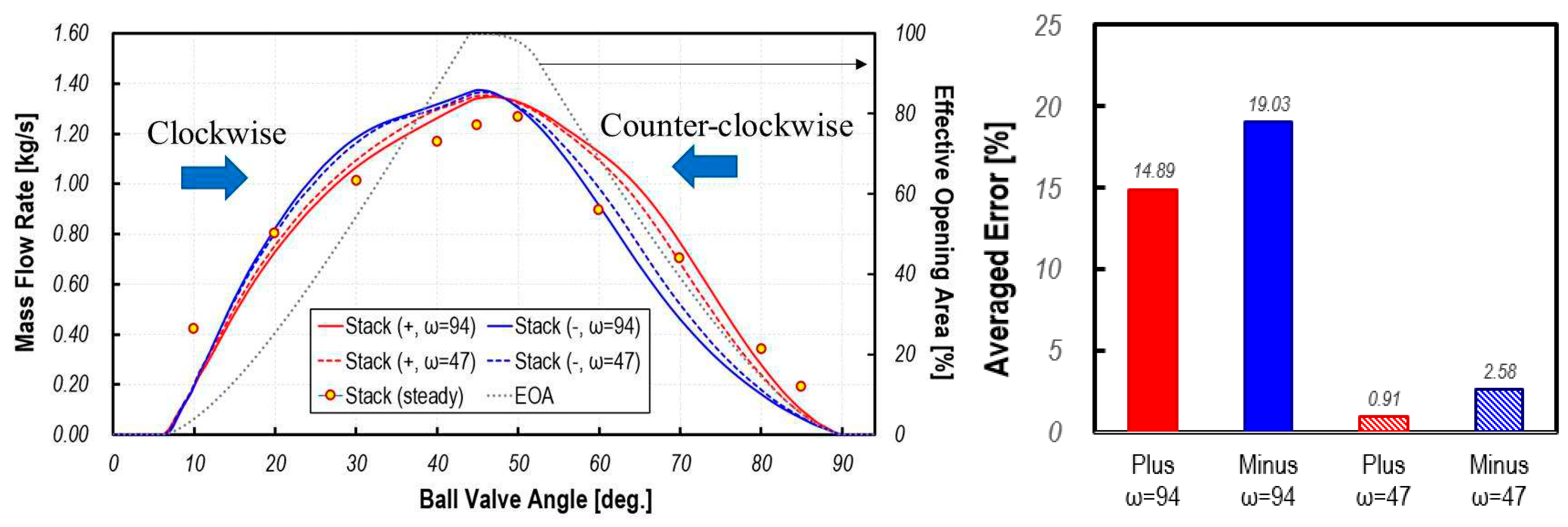
Figure 8.
Temporal variation of mass flow rate at inlet face of COD-heater port for various rotation speeds and averaged discrepancies between transient dynamic flow analysis and steady state analysis.
Figure 8.
Temporal variation of mass flow rate at inlet face of COD-heater port for various rotation speeds and averaged discrepancies between transient dynamic flow analysis and steady state analysis.
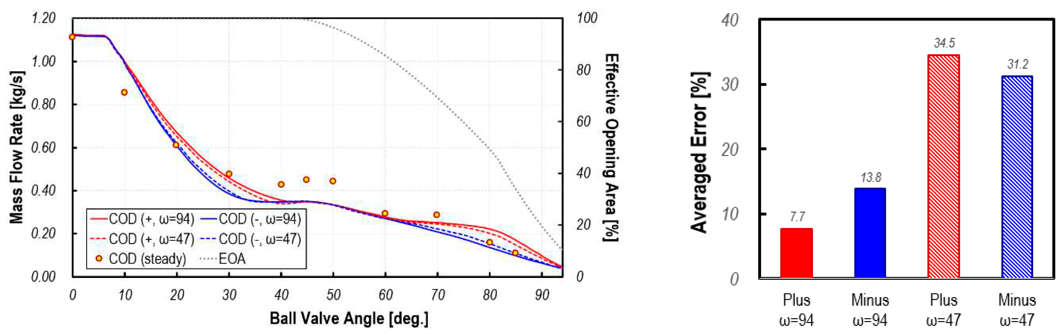
Figure 9.
Temporal variation of mass flow rate at inlet face of ion-filter port for various rotation speeds and averaged discrepancies between transient dynamic flow analysis and steady state analysis.
Figure 9.
Temporal variation of mass flow rate at inlet face of ion-filter port for various rotation speeds and averaged discrepancies between transient dynamic flow analysis and steady state analysis.
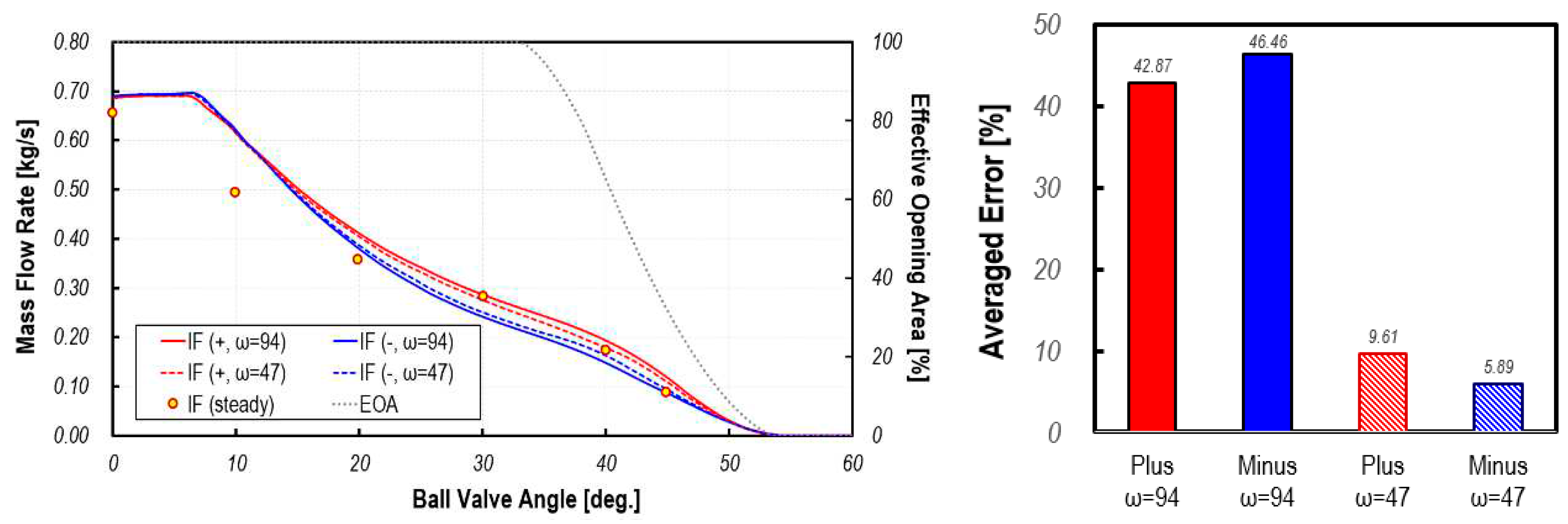
Figure 10.
Temporal variation of mass flow rate at inlet face of radiator port for various rotation speeds and averaged discrepancies between transient dynamic flow analysis and steady state analysis.
Figure 10.
Temporal variation of mass flow rate at inlet face of radiator port for various rotation speeds and averaged discrepancies between transient dynamic flow analysis and steady state analysis.
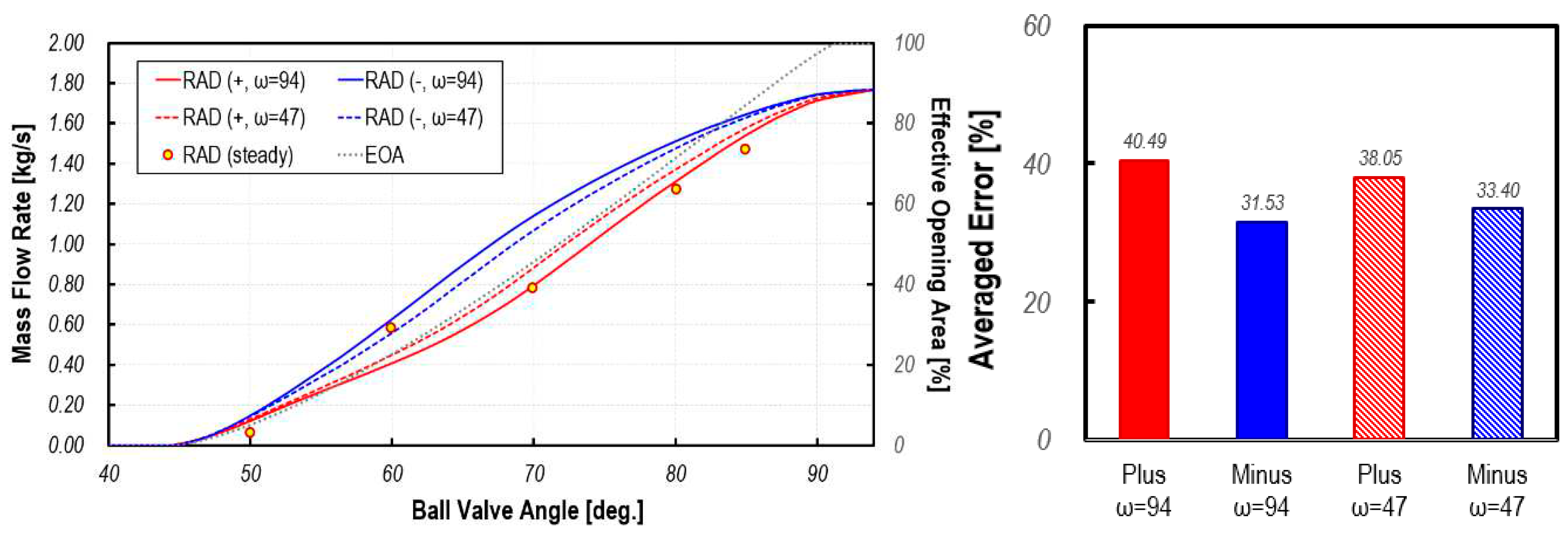
Figure 11.
Sectional view of velocity distribution in PCCV at ω=±94 deg/s and 40 deg.
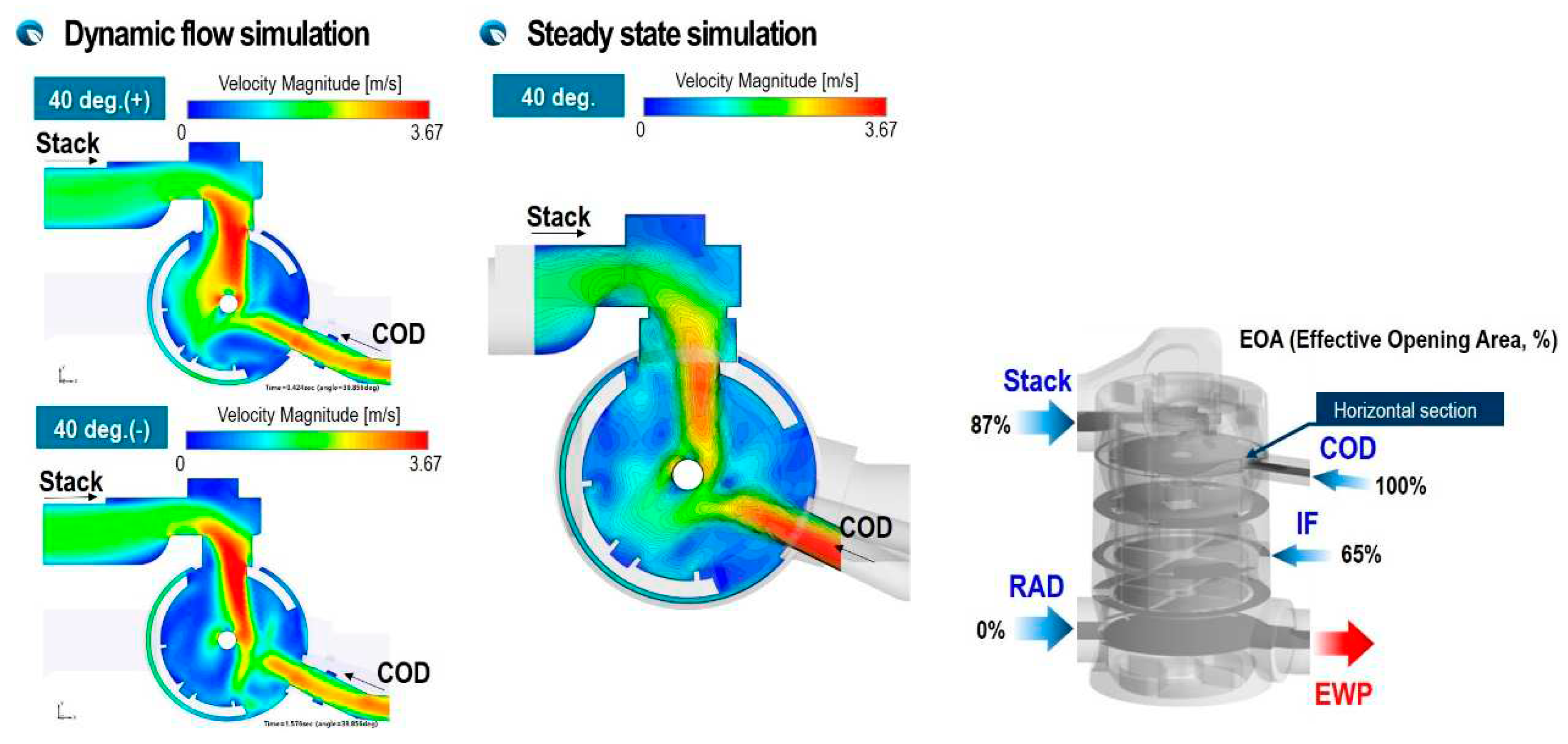
Figure 12.
Cross-section view of velocity distribution in PCCV at ω=±94 deg/s and 40 deg.
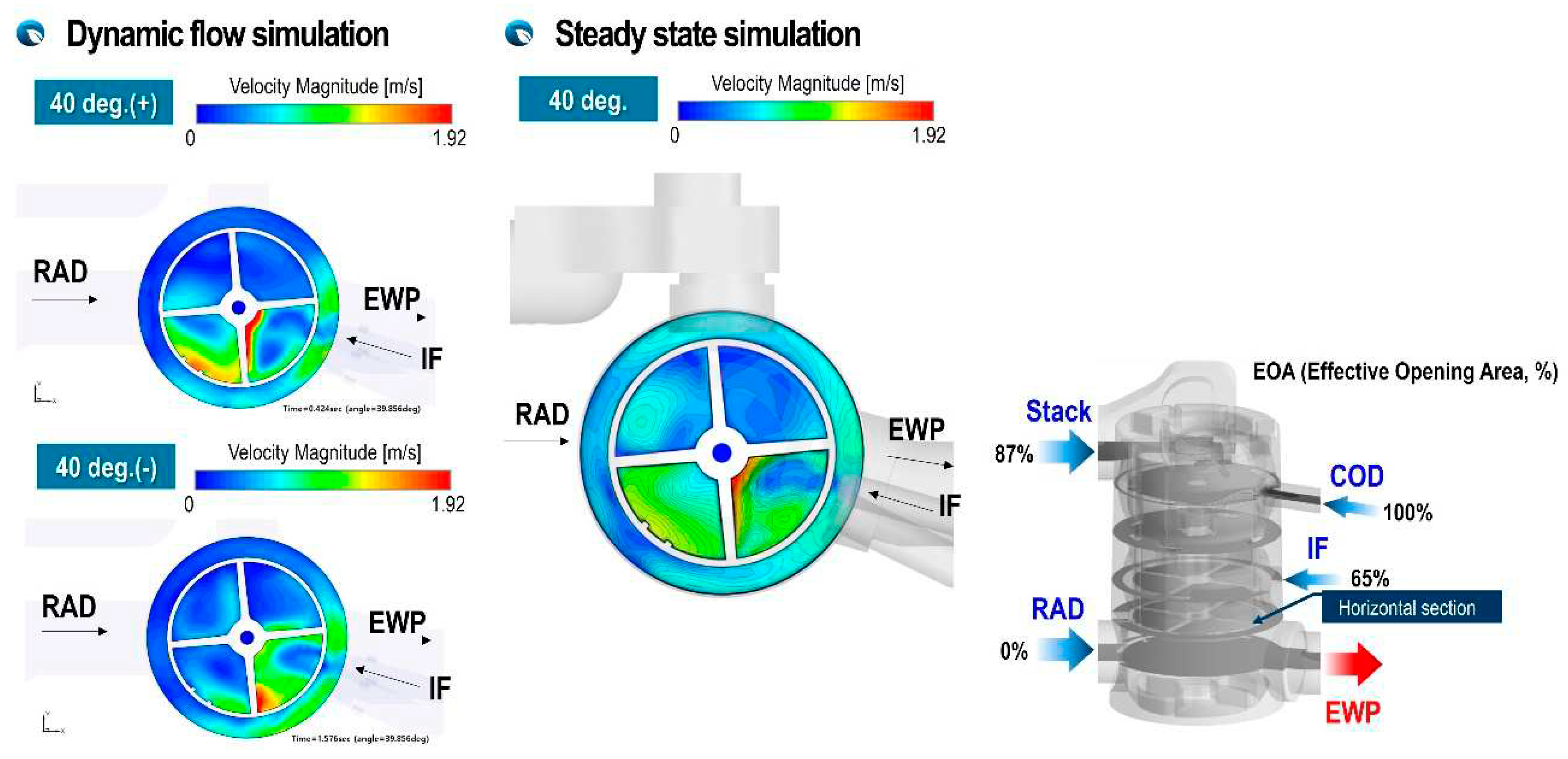
Figure 13.
Cross-section view of velocity distribution in PCCV at ω=±94 deg/s and 85 deg.
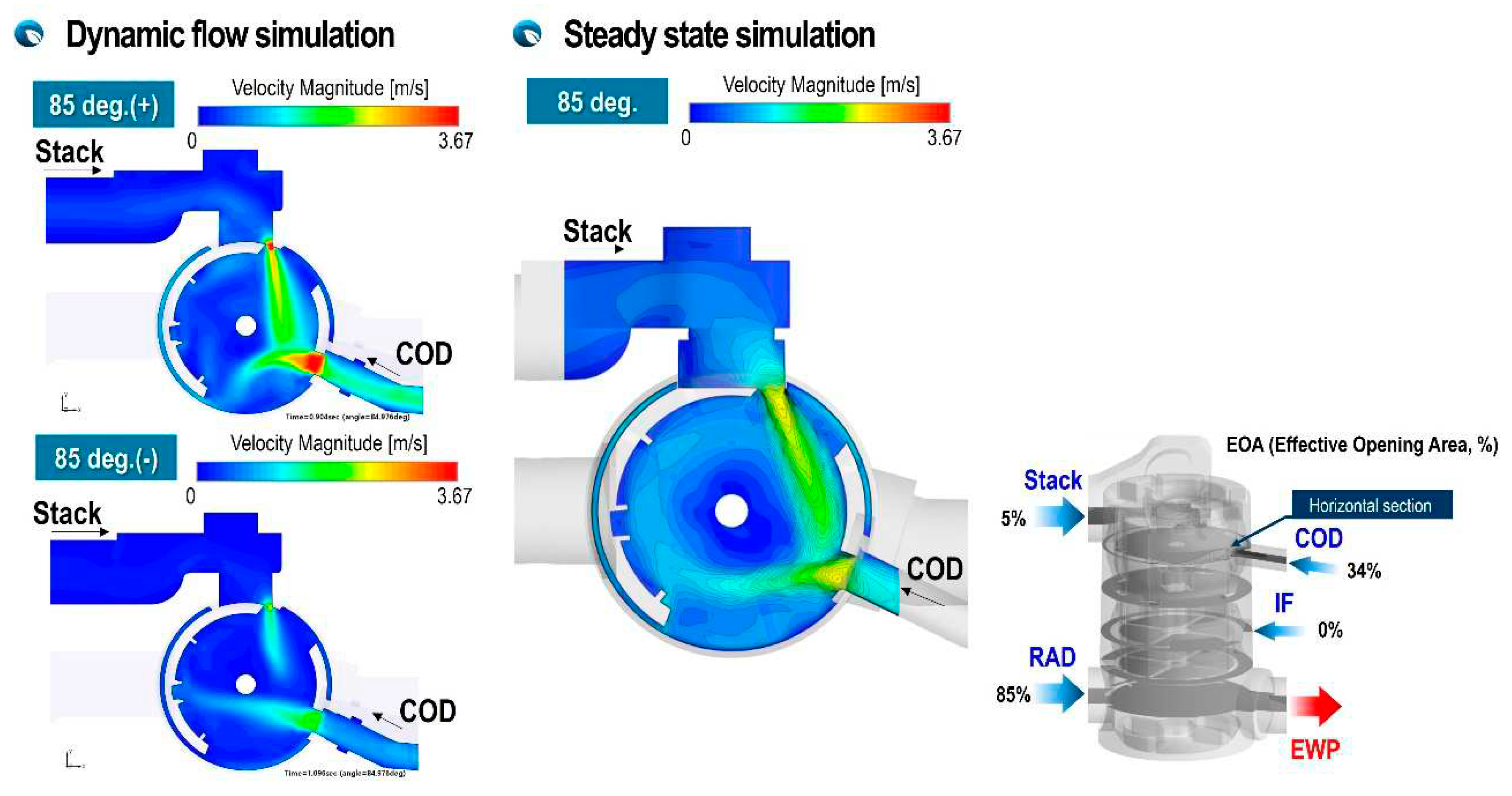
Figure 14.
Cross-section view of velocity distribution in PCCV at ω=±94 deg/s and 85 deg.
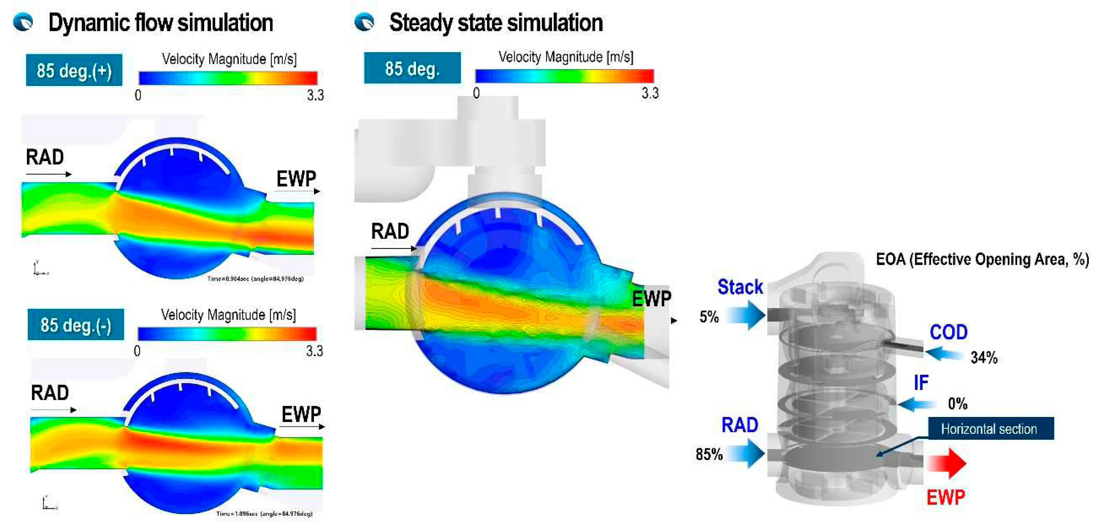
Figure 15.
Temporal sequential iso-views of particle streak lines in PCCV at ω=±94 deg/s.
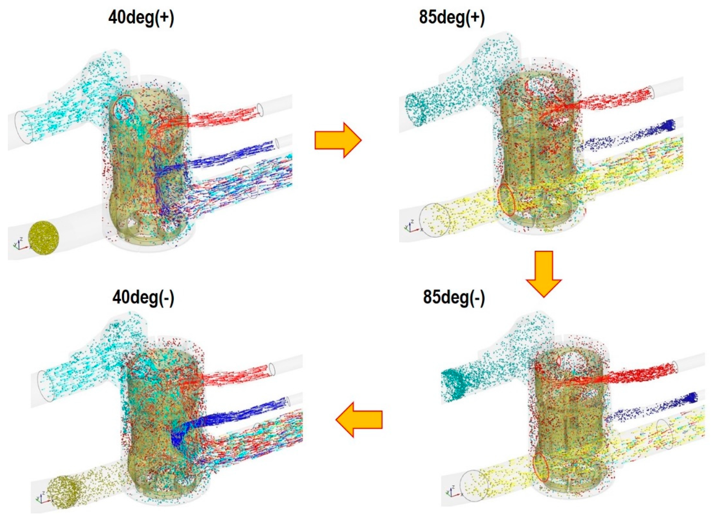
Figure 16.
Temporal variation of velocity in PCCV (a) stack port; (b) COD heater port ; (c) ion-filter port; (d) radiator port.
Figure 16.
Temporal variation of velocity in PCCV (a) stack port; (b) COD heater port ; (c) ion-filter port; (d) radiator port.
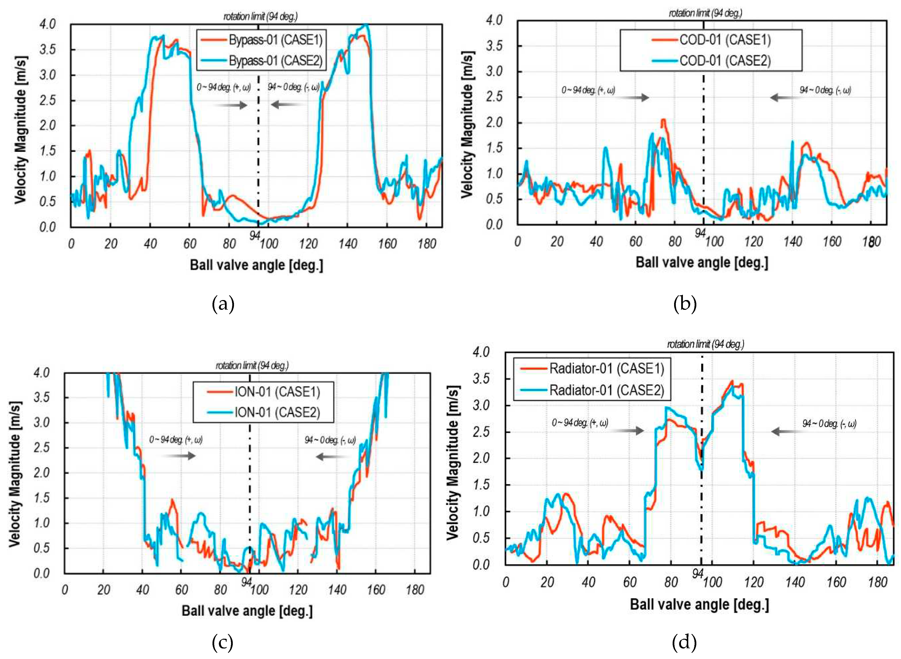
Figure 17.
Cross-sectional view of temperature distribution in PCCV at ω=±94 deg/s and 40 deg.
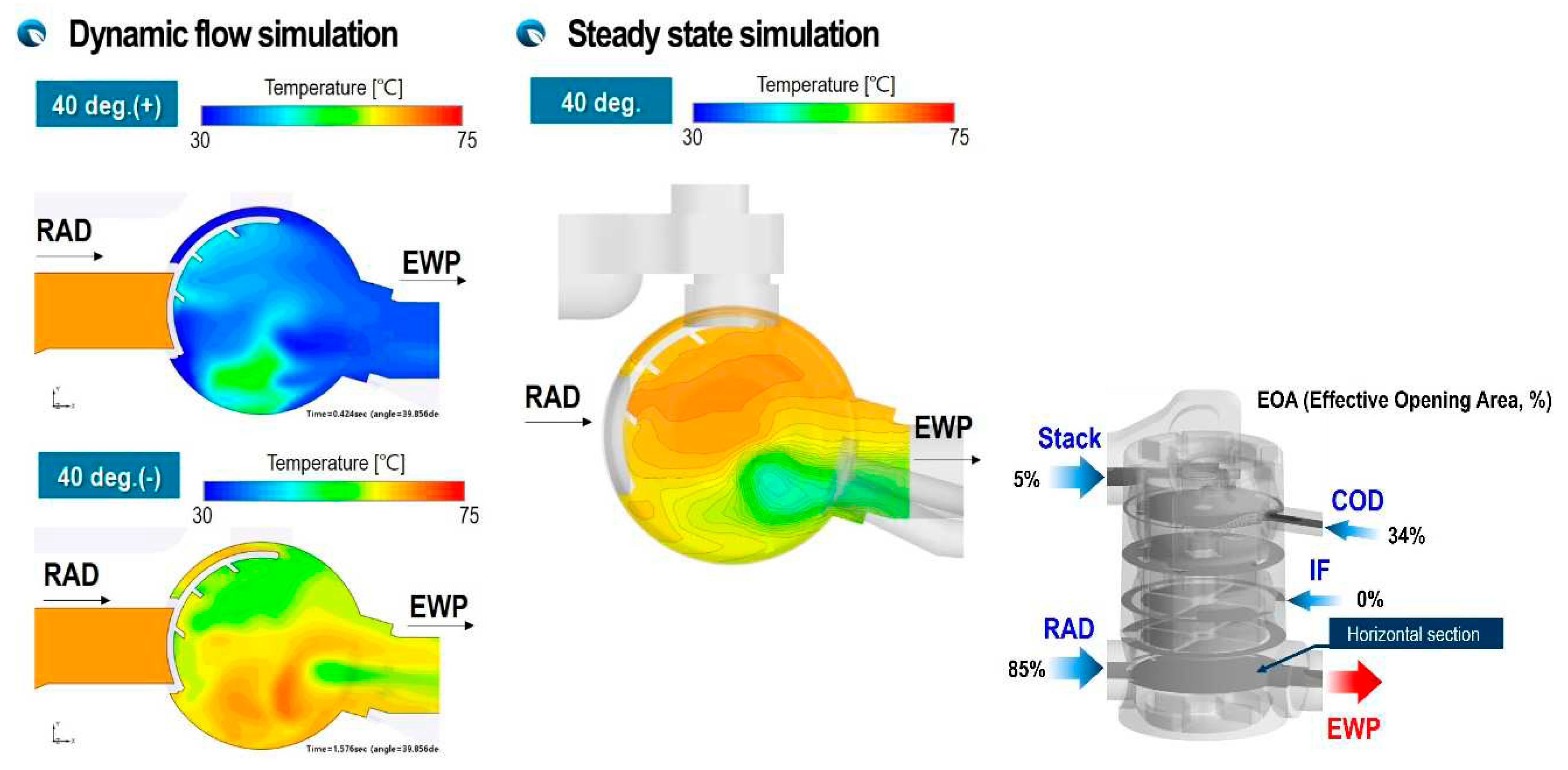
Figure 18.
Cross-sectional view of temperature distribution in PCCV at ω=±94 deg/s and 85 deg.
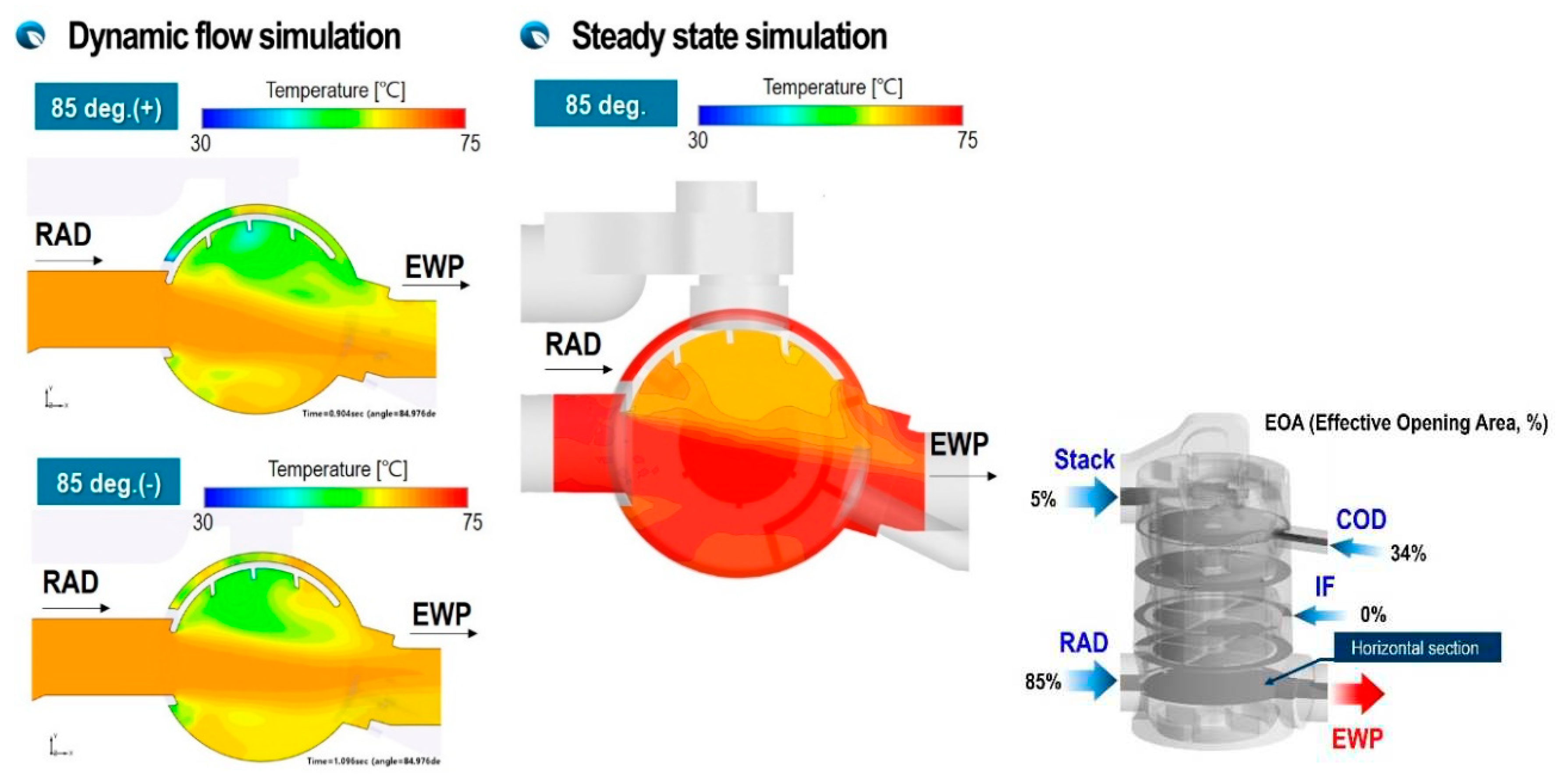
Figure 19.
Cross-sectional view of temperature distribution in PCCV at ω=±94 deg/s and 40 deg.
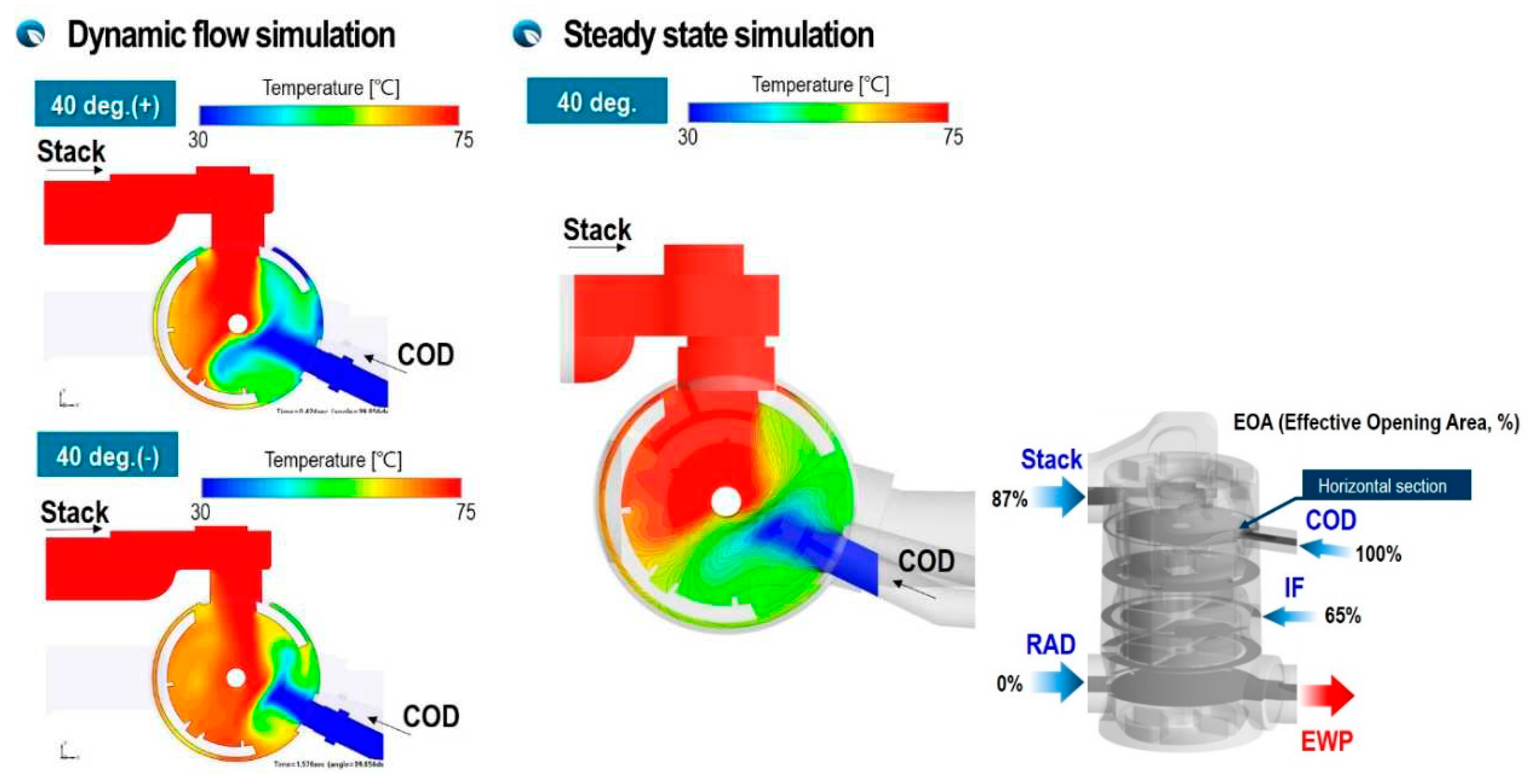
Figure 20.
Cross-sectional view of temperature distribution in PCCV at ω=±94 deg/s and 85 deg.
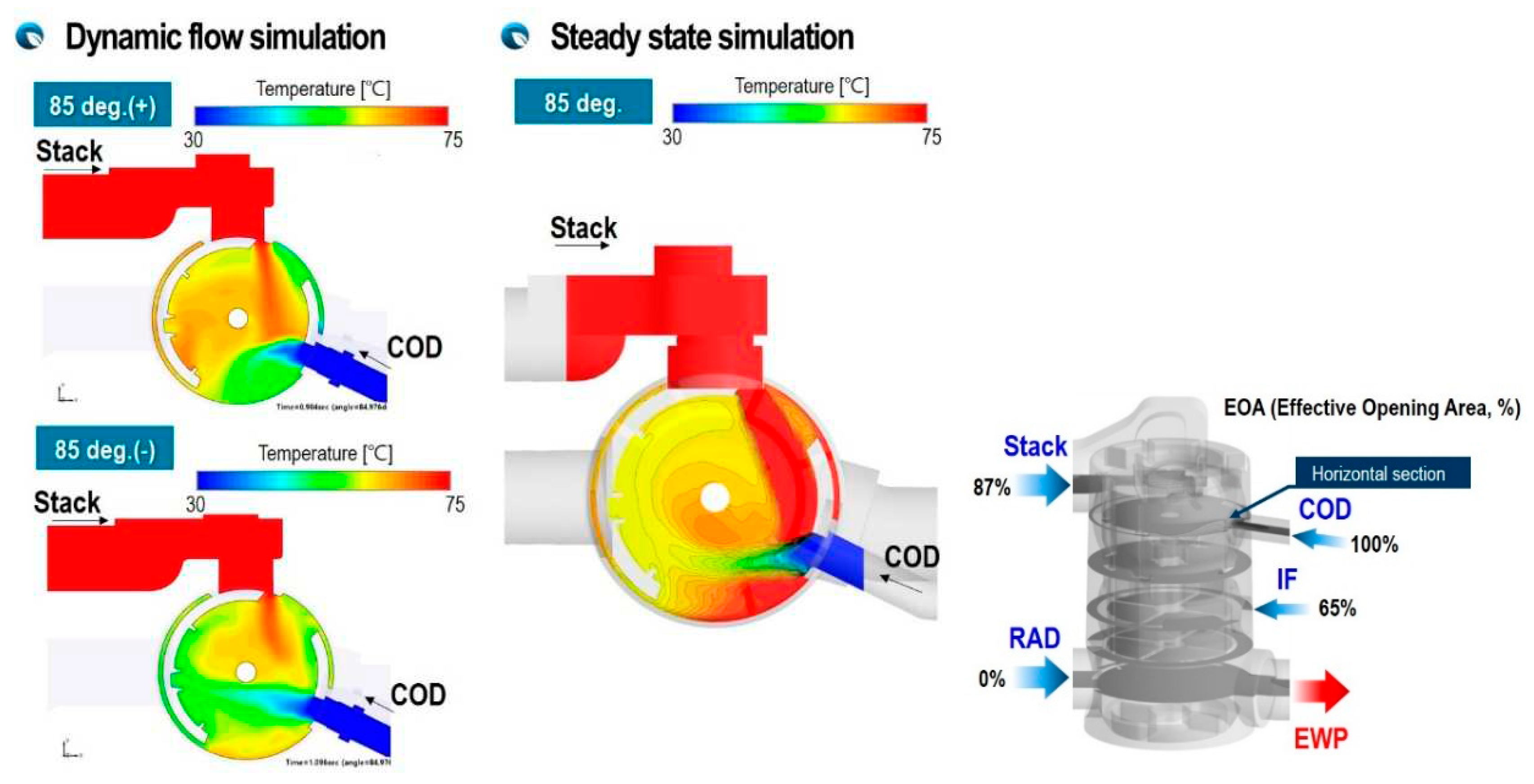
Figure 21.
Comparison of temperature at outlet between dynamic and steady flow simulation for two different rotation speeds and angles at 40 deg.
Figure 21.
Comparison of temperature at outlet between dynamic and steady flow simulation for two different rotation speeds and angles at 40 deg.
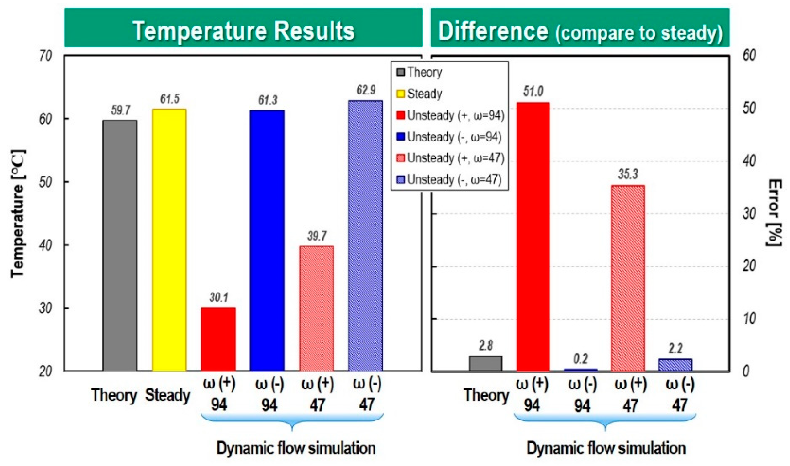
Figure 22.
Comparison of temperature at outlet between dynamic and steady flow simulation for two different rotation speeds and angles at 85 deg.
Figure 22.
Comparison of temperature at outlet between dynamic and steady flow simulation for two different rotation speeds and angles at 85 deg.
Disclaimer/Publisher’s Note: The statements, opinions and data contained in all publications are solely those of the individual author(s) and contributor(s) and not of MDPI and/or the editor(s). MDPI and/or the editor(s) disclaim responsibility for any injury to people or property resulting from any ideas, methods, instructions or products referred to in the content. |
© 2024 by the authors. Licensee MDPI, Basel, Switzerland. This article is an open access article distributed under the terms and conditions of the Creative Commons Attribution (CC BY) license (http://creativecommons.org/licenses/by/4.0/).
Copyright: This open access article is published under a Creative Commons CC BY 4.0 license, which permit the free download, distribution, and reuse, provided that the author and preprint are cited in any reuse.


