Submitted:
24 January 2024
Posted:
24 January 2024
You are already at the latest version
Abstract
Organic light-emitting diodes (OLEDs) have garnered considerable attention in academic and industrial circles due to their potential applications in flat panel displays and solid-state lighting technologies, leveraging the advantages offered by organic electroactive derivatives over their inorganic counterparts. The thin and flexible design of OLEDs enables the development of innovative lighting solutions, facilitating the creation of customizable and contoured lighting panels. Among the diverse electroactive components employed in the molecular design of OLED materials, the benzophenone core has attracted much attention as fragment for synthesis of organic semiconductors. On the other hand, the benzophenone also functions as a classical phosphor with high intersystem crossing efficiency. This characteristic makes it as compelling candidate for effective reverse intersystem crossing, potentially leading to the development of thermally activated delayed fluorescent (TADF) emitters. These emitting materials witnessed a pronounced interest in recent years due to their incorporation in metal-free electroactive frameworks and the capability to convert triplet excitons into emissive singlet excitons through reverse intersystem crossing (RISC), consequently achieving exceptionally high external quantum efficiencies (EQEs). This review article comprehensively overviews the synthetic pathways, thermal characteristics, electrochemical behaviour and photo-physical properties of the derivatives based on benzophenone. Furthermore, we explore their applications in OLED devices, both as host materials and emitters, shedding light on the promising opportunities that benzophenone-based compounds present in advancing OLED technology.
Keywords:
Donor-acceptor-donor (D-A-D) derivatives
; organic light emitting diode (OLED)
; high efficiency
; emission
; thermal analysis
; synthesis.
1. Introduction
Since C. W. Tang's ground breaking research in 1986 [1], there has been significant interest in organic light-emitting diodes (OLEDs) for several decades. Their potential applications span a wide range including full-colour flat-panel displays, smart watches, smartphones, large-screen televisions, and solid-state lighting, attracting attention in both scientific and industrial domains [2,3,4,5,6,7,8]. Today, OLEDs have evolved into a crucial commercial venture, driven by their notable advantages in terms of brightness, wide-angle view ability, power efficiency, contrast ratio, and other factors [9,10,11,12,13,14,15,16,17,18]. Flexibility stands out as an additional attribute in their technological arsenal, unmatched by any of the other existing technologies. [19,20]. Predictably, the relentless pursuit of superior OLED materials continues, driven by the quest for enhanced efficiency when incorporated into devices.
In past decades, there has been a progressive transition from fluorescence- to phosphorescence-based devices in the pursuit of higher efficiencies [21,22,23,24,25]. OLEDs utilizing conventional fluorescent dopants typically exhibit a maximum internal quantum efficiency (IQE) of 25% [1]. The IQE can be elevated from 25% to 100% by harnessing triplet excitons through the use of intersystem singlet to triplet crossing in phosphorescent emitters [26,27]. Despite the high internal quantum efficiency and operational stability of emissive iridium complexes [28,29,30,31], phosphorescent OLEDs (PhOLEDs) encounter significant efficiency roll-off due to issues like aggregation-caused quenching, triplet–triplet, and triplet–polaron annihilation [32,33,34,35]. As a result, host–guest systems are commonly employed to disperse phosphorescent emitters into host matrices. To achieve high-performance PhOLEDs, host materials must be ingeniously designed to adhere to fundamental principles such as good thermal stability and film formation quality [36,37,38,39,40,41], and a sufficiently high triplet energy to prevent reverse energy transfer from emitter to host [42,43,44]. Nevertheless, the persistent issue of poor stability of blue phosphorescent OLEDs remains a significant constraint [45,46]. The presence of noble metals in phosphorescent materials raises an undeniable challenge to the future cost of devices and environmental considerations [47,48]. In recent years, there has been a notable focus on thermally activated delayed fluorescence (TADF) materials. This interest arises from their utilization in metal-free electroactive frameworks and the ability to upconvert full triplet excitons into emissive singlet excitons through reverse intersystem crossing (RISC), thereby achieving ultrahigh external quantum efficiencies (EQEs) [49,50,51,52,53,54,55]. Despite the promise of TADF materials, many TADF OLEDs encounter substantial efficiency roll-off at high luminance due to issues such as concentration quenching, triplet–triplet annihilation, and singlet–triplet annihilation enhanced by a long exciton lifetime[56,57,58]. Consequently, to address the concentration quenching problem, most highly efficient TADF OLEDs incorporate TADF molecules into suitable host matrices. However, because of a limited selection of host materials available for TADF OLEDs [59,60,61], researchers often utilize conventional host materials common to phosphorescent OLEDs [62]. Therefore, one approach to overcoming efficiency challenges is the design of new host materials specifically tailored for TADF OLEDs. Another approach involves the development of new TADF molecules, especially for nondoped OLEDs based on materials exhibiting aggregation-induced emission (AIE) characteristics [63,64,65,66,67,68,69]. Units derived from benzophenone are renowned for their efficient intersystem crossing (ISC) capability, attributed to robust spin–orbit coupling [70]. This characteristic renders them highly appealing as acceptor blocks for fabrication of the TADF emitters. Notably, benzophenone is recognized for its stability as an acceptor [71]. Furthermore, benzophenone functions as a classical phosphor with a high intersystem crossing efficiency, potentially leading to effective reverse intersystem crossing with a small ΔEST [72]. The benzophenone framework not only serves as an electron-deficient core by integrating various donor units to create molecules with small ΔEST and intramolecular charge transfer (CT) states[73], but it also features a highly twisted geometry, reducing intermolecular interactions and the self-quenching effect [74,75].
In this review article, we examine the synthetic pathways, thermal characteristics, electrochemical behaviour, photoelectrical and photo-physical properties of derivatives based on benzophenone. Additionally, we explore their applications in OLED devices, both as host materials as well as emitters. The article will systematically review various device structures and their corresponding performances. The review is structured into several sections based on the application and structure of benzophenone derivatives, including: host materials for phosphorescent emitters, host materials for TADF emitters, donor-acceptor (D-A) type emitters, donor-acceptor-donor (D-A-D) type symmetric structure emitters, D-A-D type asymmetric structure emitters as well as emitters having dendritic structures.
2. Benzophenone-based host materials used for phosphorescent emitters.
Scheme 1 illustrates the configurations of benzophenone-based derivatives, employed as host materials in PhOLED devices. The objective compounds HA1, HA2 and HA3 [76] were obtained using relatively simple nucleophilic aromatic substitution reaction between 3,3′-dibromobenzophenone and 1,2,3,4-tetrahydrocarbazole for HA1, phenoxazine for HA2 and 9,9-dimethyl-9,10-dihydroacridine for HA3. Host material HA4 [77] was synthesized by utilizing Suzuki coupling reaction [78] between 3,3′,6,6′-tetrabromobenzophenone and 9-phenyl-9H-carbazol-3-ylboronic acid. To obtain target compound HA5 [79] Buchwald–Hartwig [80] amination reaction of 4,4’-dibromobenzophenone with 3,6-diphenyl-9H-carbazole donor unit was used. Material HA6 [81] was synthesized utilizing similar reaction conditions between 4-bromo-3-methylbenzophenone and 3,6-dimethyl-9H-carbazole. The Host material HA7 [82] was acquired through a single-step synthetic procedure employing Ullmann reaction [83] between iodophenylketone and aminodiphenylketone. The synthesis of the remaining PhOLED host materials HA8, HA9, and HA10 [84] was easily achieved through a simple Friedel−Craft benzoylation reaction [85] carried out in carbon disulfide. Benzoyl chloride, in the presence of AlCl3 reacted with 1,4-diphenyldurene, 1,3,5-triphenylmesitylene and 3,3′,5,5′-tetraphenylbimesitylene to yield HA8, HA9 and HA10, respectively.
Thermal, electrochemical, photoelectrical and photo-physical properties of the materials HA1 – HA10 are displayed in Table 1.1. The thermal properties were investigated for all the objective materials. All the derivatives showed good thermal stability with high thermal decomposition temperatures (TD) of 218 – 553 oC as confirmed by thermo-gravimetric analysis (TGA). Differential scanning calorimetry (DSC) measurements showed that the derivatives HA1, HA4, HA6, HA7 and HA10 were fully amorphous materials with glass transition temperatures (TG) of 55 – 188 oC. Only melting temperatures (TM) of 118 – 370 oC were detected for other presented materials. During cooling, crystallization temperatures (TCr) of 62 oC and 269 oC were detected for compounds HA2 and HA3, respectively. For this group of materials HOMO levels were measured to be from -5.80 eV to -4.74 eV and LUMO levels were in a region of -2.80 eV to -1.83 eV attributing to bandgap energies (Eg) of 2.72 – 3.93 eV. Benzophenone-based PhOLED host materials showed high triplet state energy (ET) levels, which were in a range of 2.53 eV – 3.02 eV. All these properties were suitable to test the materials as hosts for various phosphorescent emitters.
Architectures of devices utilizing host materials HA1 – HA10 are shown in Table 1.2. While all the devices used indium tin oxide (ITO) as anode, hole transporting layers (HTL) had more variability. All the reviewed devices used two HTLs of different derivatives stacked on top of each other. Various materials were used in forming HTLs, such as 1,1-bis[(di-4-tolylamino)phenyl]cyclohexane (TAPC), 1,3-bis(N-carbazolyl)benzene (mCP), poly(3,4-ethylenedioxythiophene):polystyrene sulfonate (PEDOT:PSS), N,N′-di(1-naphthyl)-N,N′-diphenyl-(1,1′-biphenyl)-4,4′-diamine (NPB), tris(4-carbazoyl-9-ylphenyl)amine (TCTA) and 1,4,5,8,9,11-hexaazatriphenylenehexacarbonitrile (HAT-CN). In emissive layers, iridium-based phosphorescent emitters were doped in host materials HA1 – HA10, using various doping concentrations. Bis(1-phenylisoquinoline)(acetylacetonate)iridium(III) (Ir(piq)2acac), bis[2-(3,5-dimethylphenyl)-4-methyl-quinoline](acetylacetonate)iridium(III) (Ir(mphmq)2(tmd)), bis(2-methyldibenzo[f,h]quinoxaline)(acetylacetonate)iridium(III) (Ir(MDQ)2acac), bis(2-benzo[b]thiophen-2-yl-pyridine)(acetylacetonate)iridium(III) (Ir(btp)2acac) and bis(2-benzothiozolato-phenyl)(pylbenzamidinate)iridium(III) (Ir(bt)2(dipba)) were used for red, bis(7,8-benzoquinolinato)(N,N’-diisopropylbenzamidine) iridium (III) ( Ir(bzq)2(dipba)) for orange, bis(4-phenylthieno[3,2-c]pyridinato-N,C2') (acetylacetonate) iridium(III) (PO-01) for yellow, bis[2-(2-pyridinyl-N)phenyl-C](acetylacetonato)iridium(III) (Ir(ppy)2acac) and tris(2-phenylpyridine)iridium(III) (Ir(ppy)3) for green and bis[2-(4,6-difluorophenyl)pyridinato-C2,N](picolinato)iridium (FIrpic) for blue devices. For electron transporting layers (ETLs) 4,6-bis(3,5-di(pyridin-3-yl)phenyl)-2-methylpyrimidine (B3PYMPM), 4,6-Bis(3-(9H-carbazol-9-yl)phenyl)pyrimidine (CzPhPy) and 1,3,5-tris(3-pyridyl-3-phenyl)benzene (TmPyPB) were used. Additionally, 4,7-diphenyl-1,10-phenanthroline (Bphen), lithium fluoride (LiF), lithium-8-hydroxyquinolinolate (Liq) or cesium carbonate (Cs2CO3) were deposited as electron injecting layers (EILs). Lastly, all of devices mentioned in this chapter were using aluminium (Al) as a cathode.
Characteristics of phosphorescent OLED devices using host materials HA1 – HA10 are shown in Table 1.3. Overall, utilization of benzophenone-based host materials resulted in efficient PhOLED devices with external quantum efficiency of most devices exceeding 10%. Host materials HA1-HA10 were used for red, orange, yellow, green, and blue devices. Comparison of the red devices with each other showed that the most efficient prototype was D3HA5 which has demonstrated low turn-on voltage (VON) of 2.9 V, high power efficiency (PE) of 27.1 lm/W and external quantum efficiency (EQE) of 22.1% as well as maximum brightness (LMAX) of 10240 cd/m2. For orange emitter only 3,6-diphenylcarbazol-9-yl substituted host HA5 was used. The device D2HA5 demonstrated VON, LMAX, PE and EQE of 2.6 V, 31200 cd/m2, 61.6 lm/W and 23.1%, respectively, with CIExy coordinates of (0.51, 0.47). Between yellow devices, prototype D4HA8 stood out the most and outperformed devices D4HA9 and D4HA10. That could be assigned to the structure of host material HA8 that utilizes two benzophenone fragments compared to three of HA9 and four of HA10. Diode D4HA8 demonstrated current efficiency (CE) of 50.6 cd/A, PE and EQE of 28.9 lm/W and of 19.2%. Comparing green PhOLEDs, two carbazole fragments having host material HA5 outperformed other host materials that had one or four carbazole fragments (HA4, HA6) or without carbazole fragments (HA8, HA9, HA10). Furthermore, the suitability of derivative HA5 (ET = 2.69 eV) for green phosphors could be ascribed to the highest efficiency observed in the devices. PhOLED with D1HA5 host demonstrated very high PE of 99.1 lm/W and excellent EQE of 25.1% with LMAX exceeding 93300 cd/m2. When comparing blue PhOLEDs, device using host material HA6 with high ET of 3.00 eV and excellent thermal and film forming properties exhibited the best characteristics. Device D1HA6 displayed high PE and EQE of 38.2 lm/W and 19.4%, respectively.
3. Benzophenone-based bipolar host materials used for TADF emitters
Scheme 2 illustrates the configurations of benzophenone-based derivatives, employed as host materials in TADF OLED devices. Objective compounds HB1 and HB2 [86] were synthesized via a straightforward one-step Friedel-Crafts reaction utilizing readily available, cost-effective triphenylamine and isophthaloyl or terephthaloyl dichloride as initial reagents. All the remaining host materials HB3, HB4 [87], HB5 [88], HB6, HB7 [89] and HB8 [90] were obtained by simple nucleophilic substitution reactions between fluorinated benzophenone and corresponding amines. For application as TADF host materials, benzophenone was combined either with carbazole or phenyl-/naphtyl- amino fragments as electron donors. 4,4’-difluorobenzophenone reactions with N-phenyl-1-naphtylamine, N-phenyl-2-naphtylamine, 3-naphthyl-9H-carbazole, 3-phenyl-9H-carbazole and 3-(4-(9H-carbazol-9-yl)phenyl)-9H-carbazole yielded in compounds HB3, HB4, HB5, HB6 and HB7, respectively. Material HB8 was obtained during reaction between 2,3,4,5,6-pentafluorobenzophenone and 9H-carbazole.
Table 2.1 presents the thermal, electrochemical, photoelectrical, and photo-physical properties of materials HB1 to HB8. During investigation of thermal properties, it was noticed that most of benzophenone-based compounds were resistant to heat with thermal decomposition temperatures ranging from 277 oC to as high as 497 oC. Most of the same materials also possessed the ability to form stable amorphous films with glass transition temperatures ranging from 90 oC to 187 oC. At the same time, HB series benzophenone derivatives had optical bandgap energies of 2.70 – 4.10 eV, singlet state energy (ES) levels were 2.37 – 3.07 eV, meanwhile triplet state energies ranged from 2.32 eV to 2.64 eV. Notably, carbazole-substituted derivatives HB5-8 demonstrated higher ET levels.
The configurations of devices employing host materials HB1 to HB8 are illustrated in Table 2.2. All the manufactured devices used ITO anode. To lower hole injection barrier molybdenum (VI) oxide (MoO3) was used as hole injection layer (HIL) for devices DHB3 and DHB4. Most popular material of choice for formation of hole transporting layers was PEDOT:PSS. NPB, TAPC or a cross-linkable molecule 3,6-bis(4-vinylphenyl)-9-ethylcarbazole (VPEC) were also employed for HTLs in some cases. Each device utilized one or two hole transport layers (HTLs). The chosen TADF emitters included orange 1,2,3,5-tetrakis(carbazol-9-yl)-4,6-dicyanobenzene (4CzTPN), green 2,3,5,6-tetracarbazole-4-cyano-pyridine (4CzCNPy), and blue 10,10'-(perfluoro-[1,10-biphenyl]-4,4'-diyl)bis(2,7-ditert-butyl-9,9-dimethyl-9,10-dihydro-acridine) (PFBP-2b). The electron transporting layers utilized compounds such as TmPyPB, TPBi, and 2,4,6-tris[3-(diphenylphosphinyl)phenyl]-1,3,5-triazine (PO-T2T). Finally, for all devices under investigation, a combination of LiF as the electron injecting layer and an Al cathode was employed.
Measured characteristics of TADF OLED devices employing host materials HB1 – HB8 are shown in Table 2.3. Most of the HB materials were used to dope green TADF emitters in, except benzophenone derivatives HB3 and HB5 which were used in combination with orange and sky-blue dopants to achieve white emission. Hu and co-authors investigated electron donating triphenylamino and electron accepting phthaloyl moieties having compounds HB1 and HB2. When these materials were used as hosts for green TADF emitter, compound HB1 prevailed as more effective choice that could be explained by higher singlet and triplet energy levels that enhances energy transfer efficiency and effectively prevents reverse energy transfer from the green TADF emitter to the TADF host resulting in CE, PE and EQE of 43.5 cd/A, 33.3 lm/W and 13.0 % for device DHB1, respectively. Materials HB3 and HB4 were investigated by Mahmoudi et al. They found that the best use of the synthesized materials would be as exiton modulators between two TADF emitters. By combining orange and blue TADF materials with the new benzophenone-based hosts efficient white TADF OLEDs were introduced with EQE for devices DHB3 and DHB4 reaching 9.5 % and 7.1 %, respectively. Device utilizing compound HB3 showed higher quality white electroluminescence which is defined by CIE coordinates of (0.32, 0.31), a colour temperature of 4490 K, and a colour rendering index of 80. Team of researchers lead by Swyamprabha synthesized and characterized 3-naphtyl-9H-carbazole substituted derivative HB5. Green TADF OLED device showed maximum CE, PE and EQE of 9.5 cd/A, 8.4 lm/W and 2.8 %. The same researchers continued their work and synthesized new materials HB6 and HB7 with different substituents at carbazole core. At last, green solution-processable OLEDs were also fabricated with a cross-linkable hole transport material VPEC and realized PE of 63.6 lm/W with EQE of 25.3% for device D2HB7, which was more effective than analogical device with lower ET having host material HB6. Wang et al. introduced new penta-carbazole substituted benzophenone derivative HB8, which also have been tested as host material for green TADF emitter. Device DHB8 displayed a yellowish-green emission, possessing CIE coordinates of (0.34, 0.58), aligning with the emission characteristics of 4CzCNPy [91]. The OLED achieved maximum current and external quantum efficiency, reaching 38.3 cd/A and 12.5%, respectively.
4. Benzophenone-based emitters employing D-A molecular structure.
Scheme 3 illustrates the structures of donor-acceptor type molecules reviewed for their application as emitters in OLED devices. The compounds EA1, EA2, EA3 [92], EA6 [93], EA7 [94], EA8 [95], EA13 [96], EA14 [97], EA16 [98], EA17, and EA18 [99] were synthesized using the Buchwald-Hartwig coupling reaction methodology. Specifically, EA1, EA2, and EA3 were obtained in reaction of 4-bromobenzophenone with 3-(4-(diphenylamino)phenyl)-9H-carbazole, 2-(4-(diphenylamino)phenyl)-9H-carbazole, and 1-(4-(diphenylamino)phenyl)-9H-carbazole, respectively. EA6 and EA7 were derived from the reactions of 4-bromobenzophenone with 11-phenyldihydroindolo[2,3-a]carbazole or N,N’-diphenyltriazatruxene. EA8 resulted from the reaction of 4-aminobenzophenone with 3-iodo-9-ethylcarbazole. Emitters EA13, EA14, and EA16 were synthesized through the reactions of 4-bromobenzophenone with 9,9-dimethyl-9,10-dihydroacridine, 10H-phenothiazine or 9,9-diphenyl-9,10-dihydroacridine, respectively. Lastly, by employing 9,9-dimethyl-9,10-dihydroacridine in reaction with (4-bromophenyl)(4-(phenylthio)phenyl)methanone resulted in EA17 and 9,9-dimethyl-9,10-dihydroacridine reaction with (4-bromophenyl)(4-(phenylsulfonyl)phenyl)methanone was used to obtain EA18. Materials EA4 and EA5 [100], featuring 3,6-pyridinyl-9H-carbazole substitutions, were synthesized through Suzuki reactions. This involved the coupling of 4-(3,6-dibromocarbazol-yl)benzophenone with 4-pyridinylboronic acid for the production of compound EA4 or with 3-pyridinylboronic acid for the synthesis of derivative EA5. The Suzuki coupling method was also employed for the synthesis of target materials EA9 [101] and EA22 [102]. For EA9, the reaction involved 4-bromobenzophenone with 9-phenylcarbazole-3-boronic acid pinacol ester. For derivative EA22, the initial reagents selected were 4-(4-(3-bromo-9H-carbazol-9-ylbenzoyl)benzonitrile and (4-(diphenylamino)phenyl)boronic acid. Benzophenone-based derivatives EA10 [103], EA11 [90], EA12 [104], and EA19 [105] were synthesized through relatively straightforward catalyst-free nucleophilic substitution reactions. For EA10, the initial reactants included 4-fluorobenzophenone and triphenyl-2-(9H-carbazol-2-yl)ethylene. The synthesis of material EA11 is detailed in a previous chapter under the name HB8. The objective compound EA12 was obtained by reacting of 2,3,4,5,6-pentafluorobenzophenone with 3,6-bis(tert-butyl)-9H-carbazole. Emitter EA19 was prepared through the reaction of (4-(dodecyloxy)phenyl)(4’-fluorophenyl)methanone with 9,9-dimethyl-9,10-dihydroacridine. An alternative synthesis approach was employed for the creation of compounds EA15 and EA21 [106]. In this scenario, 10H-spiro(acridine-9,9’-thioxanthene) was employed in Ullmann reactions with 4-bromobenzophenone and (6-bromopyridin-3-yl)(phenyl)methanone, respectively. The phosphorus-containing emitter EA20 [107] was synthesized through a palladium-catalyzed reaction between the intermediate compound 4-iodo-4’-phenothiazin-10yl-benzophenone and diphenylphosphine oxide in the presence of triethylamine.
The thermal, electrochemical, photoelectrical, and photo-physical properties of materials HB1 - HB8 are provided in Table 3.1. All the tested materials exhibited good thermal stability, as verified by the TGA measurements conducted on the samples. The thermal decomposition temperatures for these materials ranged from 278 oC to 497 oC. DSC experiments showed that most of the tested materials were capable of forming stable amorphous layers with glass transition temperatures of 80 – 194 oC. By analysing HOMO–LUMO gap (energy bandgap Eg) it was seen that most of the EA series derivatives demonstrated Eg levels of around 3 eV or slightly lower. Only materials EA4 and EA5 showed significantly higher Eg levels of around 4 eV, which might lead to less efficient TADF processes compared to emitters with smaller bandgaps [57]. A crucial characteristic for achievement of the TADF effect is small energy difference between the singlet and triplet states (ΔEST), which facilitates effective reverse intersystem crossing, allowing the conversion of triplet excitons to singlet excitons, which is essential for delayed fluorescence [57]. This metric was measured for all benzophenone-based D-A emitters. From 22 derivatives described this chapter, 17 of them demonstrated ΔEST levels of 0.10 eV or lower. Higher singlet-triplet energy difference having derivatives could be suffering from ineffective TADF process thus lowering the overall performance of the devices. A small ΔEST is associated with a higher fluorescence quantum yield (ΦPL), as it facilitates efficient radiative decay from the triplet state to the ground state. We can compare materials EA1, EA2 and EA3 since experiments with them were executed in the same conditions. The biggest ΔEST of 0.37 eV having derivative EA2 showed lowest quantum yield (ΦPL) of 20% in thin film. On the other hand, narrowest singlet-triplet energy gap of just 0.02 eV was measured for compound EA3, which exhibited the highest ΦPL of 50%. This trend could be observed in other pairings of similar structure materials that were characterized in the same conditions such as EA4 and EA5 as well as EA15 and EA21. Oxygen molecules can quench the triplet states involved in the TADF process [108]. This quenching effect can lead to a decrease in the efficiency of delayed fluorescence and, consequently, reduced performance of TADF-based devices. Triplet state involvement in overall emission is proved by this way for benzophenone derivatives EA5, EA6, EA8 and EA11. In case of materials EA6, EA13, EA15, EA16 and EA21 prompt and delayed components of emissions were detected with the ratio of delayed component in overall emission (RD) ranging from 37.9% to 81.3%. All emitters described in this chapter, except fluorescent EA10, exhibited TADF properties.
Architectures of devices utilizing emitters EA1 – EA22 are displayed in Table 3.2. As it was mentioned in earlier chapters, all of the devices formed with the D-A type benzophenone emitters used ITO anode and Al cathode except for EA20-based devices, which used cathodes made of blend of magnesium and silver. To lower hole injection barrier, hole injecting material MoO3 was used in some devices. Hole transporting layers were made utilizing PEDOT:PSS, NPB, TAPC, HAT-CN, TCTA, 9-(4-tert-butylphenyl)-3,6-bis(triphenylsilyl)-9H-carbazole (CzSi), mCP, 3,3′-di(9H-carbazol-9-yl)-1,1′-biphenyl (mCBP), 4,4′-bis(9-carbazolyl)-1,1′-biphenyl (CBP) or N,N'-bis(naphthalen-1-yl)-N,N'-bis(phenyl)-2,2'-dimethylbenzidine (α-NPD). Doped and non-doped emissive layers (EMLs) were used during studies of the devices. In the case of doped devices, host materials bis[2-(diphenylphosphino)phenyl]ether oxide (DPEPO), 3,6-di(9-carbazolyl)-9-(2-ethylhexyl)carbazole (TCzl), mCP, bis-4-(N-carbazolyl)phenyl)phenylphosphine oxide (BCPO), 10-(4-(4-(9H-carbazol-9-yl)phenylsulfonyl)phenyl)-9,9-dimethyl- 9,10-dihydroacridine (CzAcSF) and CBP were used. To achieve desirable emission, an additional emitter: 9,9’-((2-(4’-(9H-carbazol-9-yl)-[1,10-biphenyl]-4-yl)ethene-1,1-diyl)bis(4,1-phenylene))bis(9H-carbazole) (2CzTPEPCz) was used in tandem with emissive material EA20. To balance the flow of electrons, TBPi, TmPyPB, DPEPO and B3PyPB were applied for electron transporting layers. In order to make lower electron injection barrier, LiF, Cs2CO3 or Liq were used for EILs in some cases as it could be seen in Table 3.2.
Various metrics of the OLEDs using EA derivatives are shown in Table 3.3. Green light emission of the D-A type benzophenone derivatives was the most common result with 19 from 28 of the single-emitter devices described in this chapter. There also were reported 6 blue, 3 yellow and one white OLED prototypes using materials of this group. EQE exhibited by the devices ranged widely from 1.8 % to 26.7 %. The most effective yellow OLED device was achieved by Chen and colleagues and reached maximum CE, PE and EQE of 73.1 cd/A, 38.2 lm/W and 26.7 %, respectively [109]. For all the emitters used in yellow OLED devices TADF effect has been confirmed. Zhao et al. successfully applied the same emitter EA20 in white TADF OLED prototype D2EA20 and achieved high CE of 45.9 cd/A, PE of 18.0 lm/W and EQE of 20.8 % [110]. Ho and coworkers synthesized and characterized triphenylethene-carbazole substituted benzophenone derivative EA10. Big ΔEST gap of 1.09 eV could not enable TADF process in this case. Green OLED device with DEA10 achieved EQE of 1.7 % and high luminance of 11802 cd/m2. Ma et al. tested three different benzophenone-carbazole materials EA1, EA2 and EA3 with different positions of triphenylamine moiety in the structures. The most efficient TADF emitter was compound EA3, which in a green device DEA3 reached external quantum efficiency of 7.6%. Kreiza and colleagues also achieved good results utilizing a benzophenone-based D-A TADF emitter EA12. Non-doped green OLED device D1EA12 achieved CE, PE and EQE of 19.0 cd/A, 14.9 lm/W and 10.3 %. By doping the mentioned emitter in DPEPO host, characteristics were enhanced by the authors with 34.9 cd/A, 27.3 lm/W and 12.5 % for device D2EA12. Ma and co-workers presented another very efficient green light emitting sulfone group-enriched benzophenone TADF emitter EA18. Luminance of the doped device D2EA18 surpassed 30000 cd/m2 with EQE reaching 20.6 %. Other characteristics were also impressive with CE reaching 64.6 cd/A and PE being 75.1 lm/W. Although similar structure green TADF emitter EA17 obtained by the same researchers was less efficient in doped devices, which could be attributed to absence of sulfone group. However, it was impressive when applied in non-doped EMLs: device D1EA17 achieved maximum PE, CE and EQE of 53.7 cd/A, 52.7 lm/W and 17.3%, respectively. In the realm of green light emitting devices, the TADF emitter EA21, which had one of benzophenone phenyl rings replaced with pyridine and was characterized by Wang and co-workers demonstrated superior efficiency. Luminance of the doped device D2E21 surpassed 11000 cd/m2, while EQE was 25.6 %. Other characteristics were also impressive with CE and PE reaching 69.8 cd/A and 58.9 lm/W. The same green TADF emitter was also unrivalled when applied in non-doped EML. Device D1EA21 achieved maximum PE, CE and EQE of 56.4 cd/A, 43.5 lm/W and 18.7%. These characteristics were considerably higher than those of devices D1EA15 and D2EA15, which used pyridine unmodified green TADF emitter EA15. The benzophenone fragment was also successfully applied in synthesis of blue TADF emitters. Group of researchers lead by J. Wang successfully combined benzophenone electron acceptor with 11-phenyldihydroindolo[2,3-a]carbazole electron donor and obtained material EA6. When applied as a dopant in blue OLED DEA6, maximum EQE of 17.7% and luminance of over 14000 cd/m2 were obtained Other efficiencies such as CE and PE were 44.8 cd/A and 45.6 lm/W. However, the most efficient benzophenone derivative used as blue TADF emitter was EA19, characterized by J. Zhang and his group of scientists. Relatively simple structure of benzophenone-acridine derivative was applied for blue DEA19 device and reached CE of 47.7 cd/A, PE of 29.9 lm/W and EQE of 20.6 %
5. Benzophenone-based emitters employing symmetric D-A-D structure.
Chemical structures of symmetrical benzophenone-based emitters employing donor-acceptor-donor (D-A-D) structures are shown in Scheme 4. Materials described in this chapter, have mostly central benzophenone fragment with various carbazole substituents as it is the case for compounds EB1-EB7. Acridine was also a popular fragment as an electron donor for five of the described materials EB8-EB12. Phenoxazine was a key element in 4 structures (EB13-EB16), phenyl- or naphtyl- amines were used in 3 molecules, namely EB17-EB19. In addition, various other electron donors, such as spiro-, phenoselanazine, triazatruxene and some others have been utilized. Material EB1 [111] was synthesized by utilizing Ullmann reaction between 4,4’-dibromobenzophenone and 3,6-bis(tert-butyl)-9H-carbazole. A significant number of the EB materials was synthesized through the Buchwald-Hartwig amination of 3,3’-dibromobenzophenone or 4,4’-dibromobenzophenone employing various electron-donating fragments. For example, for synthesis of compounds EB2, EB9, EB13 [76] and EB4 [79], tetrahydrocarbazole, phenoxazine, 2,7-ditert-butyl-9,9-dimethylacridine and 3,6-diphenyl-9H-carbazole respectively, served as the second reactant. The reactions of the dibromobenzophenone with carbazole resulted in material EB3, with bicarbazole yielded EB5 [73], and with 9,9,9’9’-tetramethyl-9,9’10,10’-tetrahydro-2,10’-biacridine - EB11 [112]. N-(2-naphthyl)aniline played a crucial role in obtaining EB19 [113]. Phenoselanazine, azasiline, 10H-spiro[acridine-9,9′-fluorene], 10H-spiro[acridine-9,9′-xanthene], and (10H-spiro[acridine-9,9′-thioxanthene]) were utilized for preparation of EB21 [114], EB22 [115], EB23, EB24 and EB25 [116], respectively. The synthesis of compounds EB26 and EB27 [117] involved the use of 5,10-dihexyl-10,15-dihydro-5H-diindolo[3,2-a:3',2'-c]carbazole and 5,10-diphenyl-10,15-dihydro-5H-diindolo[3,2-a:3',2'-c]carbazole as reactants. The synthesis of the benzophenone derivatives EB14, EB15 and EB16 [73], which was described in the same publication with earlier mentioned EB3 and EB5, was achieved using aminations of bis(4-bromobenzoyl)benzenes with two equivalents of phenoxazine. The same reaction methodology was used to obtain emitter EB6 [95]. In this case, amination of 3-iodo-9-ethylcarbazole with 4,4′-diaminobenzophenone took place. ((4,10-Dimethyl-6H,12H-5,11-methanodibenzo[b,f][1,5]diazocine-2,8-diyl)bis(4,1-phenylene))bis((4-bromophenyl)methanone) reacted with 9,9-dimethyl-9,10-dihydroacridine in similar conditions to prepare emitter EB12 [118]. Material EB7 [119] was synthesized during a simple nucleophilic substitution of 4,4’-diflourobenzophenone with 3-(N,N-diphenylamino)carbazole. Suzuki reaction was chosen as the best procedure for obtaining compound EB8 [120] from 4,4’-dibromobenzophenone and 9,9-dimethyl-10-phenyl-2-(4,4,5,5-tetramethyl-1,3,2-dioxaborolan-2-yl)-9,10-dihydroacridine as initial reactants. EB10 [121] was synthesized during N,N-(2,6-di(3-pentyl)phenyl) imidazolium-catalysed reaction of 4,4’-dibromobenzophenone with 9,9-dimethyl-9,10-dihydroacridine. Two compounds EB17 and EB18 [86] were obtained through a simple one-step Friedel-Crafts reaction by using commercially available cheap starting materials triphenylamine (TPA) and, correspondingly, isophthaloyl dichloride for compound EB17 or terephthaloyl dichloride for emitter EB18.
Table 4.1 depicts thermal, electrochemical and photo-physical properties of the mentioned light-emitting symmetrical benzophenone materials EB1 – EB27. The destruction temperatures were reported for eighteen compounds described in this chapter. Even though EB13 had a lowest TD of 218 oC owing to two phenoxazine fragments, it was still high enough to cope with conditions of device forming and operating, especially bearing in mind high melting temperature of 118 oC for the compound. All the other presented here emitters were characterized by TD of 270 oC or higher. Glass transition temperatures for derivatives EB1, EB2, EB7, EB17, EB18, EB19, EB26 and EB27 were registered at 90 oC or higher, so these emitters could form stable amorphous layers. Crystalline benzophenone-based materials EB4, EB9, and EB22 demonstrated melting temperatures of 300 oC or higher as it was confirmed by DSC. Examining the HOMO–LUMO gap (energy bandgap Eg), it becomes evident that the majority of the symmetrical D-A-D benzophenone derivatives exhibit measured or calculated Eg levels in the region of 2.47 – 3.37 eV. Only EB9 presented a distinctly elevated Eg level of 3.66 eV. This could be the reason of decreased quantum yield and less effective TADF processes, when compared to emitters possessing smaller bandgaps. Achieving a low ΔEST is essential in the development of an emitter to enhance the efficiency of the TADF process, as it is evident from the data of Table 4.1, where materials EB11, EB14, EB23, EB24 and EB25 with ΔEST values of 0.03 eV or lower demonstrate ΦPL exceeding 70% in nitrogen atmosphere. The participation of the triplet state in the emission process was also demonstrated for some compounds. For example, this was observed in EB6, where the overall ΦPL substantially decreased upon exposure to oxygen. In addition, in derivatives EB1, EB12, EB23, EB24, and EB25 a substantial RD levels were identified. All emitters described in this chapter, except fluorescent EB2 and EB9, exhibited TADF properties.
The majority of the D-A-D benzophenone-based derivatives were tested as emitters in OLEDs, which structures are illustrated in Table 4.2. The dominant choice for anode in these devices was also ITO. To ease energy barrier, such hole injecting materials as Mo2O3, rhenium (VI) oxide (ReO3) and MoO3 were used. NPB, α-NPD, mCP, PEDOT:PSS, TAPC, HAT-CN or TCTA were chosen for formation of hole transporting layers. To further elevate efficiency of the devices, well known hosts materials diphenyl[4-(triphenylsilyl)phenyl]phosphine oxide (TSPO1), DPEPO, TCzl, 9-(3-(9H-carbazol-9-yl)phenyl)-9H-carbazole-3-carbonitrile (mCPCN), 2,8-bis(diphenyl-phosphoryl)-dibenzo[b,d]furan (PPF), mCP, mCBP, CBP and some others were used in emissive layers. To achieve desired white-light OLEDs, some phosphorescent emitters as Ir(ppy)2(acac) or Ir(bt)2(dipba) were used in conjunction with benzophenone derivative EB4. Electron transport layers were made from DPEPO, TPBi, B3PYMPM, TmPyPB, BPhen, PPF or TSPO1. Also, LiF, Liq and rubidium carbonate (Rb2CO3) were used as electron injecting materials. For all the devices described in this chapter aluminium cathodes were used.
This chapter reviews all devices constructed by researchers utilizing benzophenone-based emitters EB1-EB27 with D-A-D structure, and the characteristics of these devices are detailed in Table 4.3. Combination of central benzophenone electron accepting group with various electron donors yielded in red, yellow, green, and blue emitters. Utilization of the described compounds with phosphorescent emitters or other benzophenone-based materials resulted in also white-light emission. Lee et al. reported the red-emitting material EB15. Device DEB15, that utilized the mentioned TADF emitter, exhibited low turn-on voltage of 2.8 V, CE of 11.1 cd/A with EQE of 4.2%. Additionally, maximum luminance of the device exceeded 50000 cd/m2. The same authors introduced blue TADF emitters EB3 and EB5, which in devices achieved EQE values of 8.1% and 14.3%, respectively, with the latter one being the most efficient blue OLED in this D-A-D group. They also presented a green TADF emitter EB14, which attained an EQE of 10.7% in its device, and a yellow TADF emitter EB16, that reached an EQE of 6.9%. Liang and co-workers presented material EB4 that could act as a host and as an emitter at the same time. For example, device D1EB4 with non-doped emitter EB4 demonstrated PE and EQE of 6.9 lm/W and 4.0 %, respectively. By combining phosphorescent emitters Ir(ppy)2(acac) and Ir(bt)2(dipba) with the compound EB4, device D2EB4 achieved white emission and demonstrated exceptionally high current efficiency of 48.6 cd/A and external quantum efficiency of 25.6%. By utilizing the symmetrical D-A-D structure researchers developed nine green TADF emitters EB6, EB10, EB11, EB14, EB20, EB21, EB23, EB24 and EB25 that achieved over 10% external quantum efficiency. EB6, designed by Tani and colleagues, was used in an emissive layer of TADF device DEB6 and achieved EQE of 10.4%. Zhang and collaborators employed a straightforward structural derivative EB10 as a non-doped TADF emitter. The resultant device exhibited excellent PE and EQE values of 59.0 lm/W and 18.0%, respectively. Liu and colleagues created a structurally similar derivative EB11, where they replaced the acridine electron donor with biacridine fragment. This modification led to a notable improvement in EQE reaching 22.5% along with an impressive CE of 69.3 cd/A. Derivatives EB20 and EB21, which were characterized by Sharif and co-workers, also were highly efficient when applied in green TADF OLED devices. By combining phenoselenazine electron donors with benzophenone, researchers synthesized EB20 and fabricated the DEB20 device, which exhibited an exceptionally high EQE of 30.8% and a CE of 64.0 cd/A. In comparison, the DEB21 device, which employed derivative EB21 with an additional ketone group as the emitter, achieved lower EQE of 18.8% but with higher CE of 73.5 cd/A. The highest overall efficiencies of green TADF OLEDs by utilizing symmetrical D-A-D benzophenone-based emitters were achieved by Huang et al., who synthesized and characterized derivatives EB23, EB24 and EB25. These materials underwent testing in both non-doped and doped emissive layers. The most efficient non-doped device D1EB23 demonstrated exceptional performance with maximal CE, PE, and EQE reaching 53.9 cd/A, 48.9 lm/W and 18.6%, respectively. In the doped device D2EB23 efficiencies were further elevated, achieving an impressive CE of 90.9 cd/A, PE of 91.2 lm/W, and EQE of 30.3%. If the device D2EB23 attained the highest CE and PE values among the green devices described in this chapter, the OLED D2EB24 with emitter EB24 doped in a host material remained unparalleled with an extraordinary high EQE level of 32.2%.
Within the realm of blue TADF emitters described in this section, aside from the previously mentioned derivatives EB3 and EB5, notable efficiencies were also observed by using EB8 and EB22 emitters in the TADF based OLEDs. The compound EB8, presented by Cai and colleagues, achieved an EQE of 8.90% in the DEB8 device. Another team led by Sun developed and utilized the TADF emitter EB22 as crucial element in the construction of the DEB22 device, displaying a VON of 3.6 V, a LMAX of 2021 cd/m² with an EQE of 11.4%. The previously mentioned EB5 emitter proved to be the most effective blue TADF emitter in this section. When integrated into a device, it exhibited a CE of 25.5 cd/A, an EQE of 14.3%, and a maximum luminance of 3900 cd/m².
6. Benzophenone-based TADF emitters employing asymmetric D-A-D structure.
Structures of benzophenone-based TADF emitters having asymmetric D-A-D molecular configurations are shown in Scheme 5. Except for one material, all others utilized carbazol-9-yl as one of the electron-donating fragments in conjunction with a benzophenone acceptor, along with other donating moieties like 3-substituted carbazole, 9,10-dihydro-9,9-dimethylacridine, spiro[acridine-9,9'-fluorene] or phenoxazine. Only the derivative EC11 did not incorporate carbazole as one of the electron donors- it employed 9,10-dihydro-9,9-dimethylacridine and thianthrene fragments. To obtain derivatives presented in this chapter, at least two synthetic steps were required. Derivative EC1 [92] was synthesized through a two-step Buchwald-Hartwig amination procedure, involving the replacement of one bromine atom in 4,4’-dibromobenzophenone with carbazole by following reaction with 4-(9H-carbazol-1-yl)-N,N’-diphenylaniline. Material EC2 [64] was obtained by reaction between (3,5-bis-carbazol-9-yl-phenyl)-(4-bromophenyl)-methanone and 9,10-dihydro-9,9-dimethylacridine under Buchwald-Hartwig reaction conditions. Derivatives EC3 and EC4 [122] were created through the two-step synthesis process. Initially, the fluorine atom of 4-bromo-4’-fluorobenzophenone was reacted with spiro[acridine-9,9'-fluorene] using a nucleophilic substitution reaction. Subsequently, the bromine atom was replaced with carbazole or 3,6-di-tert-butylcarbazole during Buchwald-Hartwig reaction. Materials EC5–EC10 were synthesized using very similar procedures [123]. In the initial step, 3,6-di-tert-butyl-9H-carbazole underwent Buchwald-Hartwig reaction with (4-bromophenyl)(4-fluorophenyl)methanone, (6-bromopyridin-3-yl)(4-fluorophenyl)methanone, or (5-bromopyridin-2-yl)(4-fluorophenyl)methanone, resulting in intermediate compounds. Subsequently, nucleophilic substitution reactions of 9,10-dihydro-9,9-dimethylacridine were employed with, correspondingly, (4-(3,6-di-tert-butyl-9H-carbazol-9-yl)phenyl)(4-fluorophenyl)methanone, (6-(3,6-di-tert-butyl-9H-carbazol-9-yl)pyridin-3-yl)(4-fluorophenyl)methanone, and (5-(3,6-di-tert-butyl-9H-carbazol-9-yl)pyridin-2-yl)(4-fluorophenyl)methanone, to yield compounds EC5, EC6, and EC7, respectively. Utilizing the same reactions with phenoxazine instead of 9,10-dihydro-9,9-dimethylacridine resulted in compounds EC8, EC9, and EC10, respectively. The synthesis of drivative EC11 involved also two-step process [124]. Initially, one bromine atom of 4,4’-dibromobenzophenone was replaced with a thianthrene moiety through a Suzuki reaction. Subsequently, the second bromine atom was substituted with 9,10-dihydro-9,9-dimethylacridine in a Buchwald-Hartwig cross-coupling reaction.
Table 5.1 presents the thermal, electrochemical and photo-physical properties of materials EC1–EC11. The asymmetric D-A-D type benzophenone derivatives exhibited exceptional thermal stability, with TD ranging from 309 to 451°C, as verified through TGA measurements. It is reported that for materials EC2 and EC11, during DSC experiments TG values were registered at 72 oC and 104 oC, respectively. The HOMO levels of materials EC1 - EC11 ranged from -5.92 to -5.23, while the LUMO levels varied between -3.09 and -2.61. The energy difference between HOMO and LUMO levels for all the materials discussed in this chapter was 2.88 eV or lower. This small bandgap facilitates a minimal energy difference between the lowest singlet and triplet states, enabling efficient reverse intersystem crossing. Experimental results support this, with ΔEST being 0.10 eV or lower, resulting in high ΦPL ranging from 33.2 % to 90.0 %. EC3 to EC11 derivatives exhibited aggregation-induced emission properties with lower ΦPL values detected in solutions compared to film states. Additionally, materials EC1 and EC3 to EC10 demonstrated significant involvement of triplet states in photon generation, as evidenced by RD ranging from 33.0% to 89.7% with one of potential light-generating mechanisms being TADF.
Every benzophenone derivative presented in this chapter underwent testing as emitter in OLED devices, with their structures depicted in Table 5.2. Consistent with earlier chapters, ITO was the only selection for the anode in these devices. To reduce the energy barrier for holes, the device DEC11 utilized MoO3 as the hole-injecting material. For this device or others, a stack of one to three layers of hole-transporting materials was employed, featuring layers composed of PEDOT:PSS, HAT-CN, TAPC, TCTA, NPB or mCP. While most devices using EC1-EC11 emitters employed non-doped configurations, some of them utilizedalso the host-guest approach. Specifically, the host material CBP was applied in device DEC2, and PPF was employed for D2EC3 and D2EC4. TPBi, TmPyPb, and PPF were employed as electron-transporting layers, while Cs2CO3 and LiF served as electron-injecting materials. For all the devices discussed in this chapter, the Al cathode was the only option.
All the recently presented derivatives EC1-EC11 underwent testing as emitters in devices. Although most of these devices displayed green emission, there were exceptions such as DEC8, which emitted yellow light, and DEC9 as well as DEC10, which emitted orange light. Ma with research team successfully synthesized and characterized EC1 derivative, revealing noteworthy characteristics. The mentioned emitter was integrated into the non-doped emissive layer of device DEC1, which demonstrated CE of 35.5 cd/A, PE of 22.3 lm/W, and EQE of 13.3%. Another derivative EC2, synthesized and characterized by Zhao et al., showcased impressive performance with CE, PE, and EQE values of 61.8 cd/A, 40.4 lm/W, and 19.7%, respectively, as well as with an impressive LMAX of 116000 cd/m2. Huang’s team developed derivatives EC3 and EC4. Among them, TADF emitter EC3-based devices exhibited the highest efficiencies between devices described in this chapter, achieving CE, PE, and EQE of 76.9 cd/A, 71.0 lm/W and 29.0% in the non-doped device D1EC3. Introducing of host material PPF in the emissive layer of the D2EC3 further elevated efficiencies to 82.9 cd/A for CE, to 70.1 lm/W for PE, and a peak EQE reached 33.3%. Although EC4 using OLEDs were slightly less efficient, D1EC4 exhibited a remarkably low VON of 3.0 V and EQE of 21.6%. D2EC4 demonstrated an impressive EQE of 32.9%, with CE and PE values of 77.2 cd/A and 65.0 lm/W. The emitting materials EC5 – EC10 were meticulously designed, synthesized, and tested by Ma and colleagues in non-doped OLED prototypes. These materials combined 3,6-di-tert-butylcarbazole donor with various other donors such as and 9,10-dihydro-9,9-dimethylacridine (EC5, EC6, EC7) or phenoxazine (EC8, EC9, EC10) with acceptors like benzophenone (EC5, EC8), phenyl(3-pyridyl)methanone (EC6, EC9) or phenyl(2-pyridyl)methanone (EC7, EC10). For instance, the incorporation of 9,10-dihydro-9,9-dimethylacridine moiety in benzophenone-based TADF emitter EC5 led to the device DEC5 with PE, CE, and EQE of 14.3 cd/A, 6.4 lm/W, and 6.70%, respectively. The incorporation of pyridinyl fragment in TADF emitter EC6 significantly improved efficiencies in its corresponding device DEC6, reaching CE of 35.4 cd/A, PE of 15.9 lm/W, and EQE of 11.4%. Phenoxazine fragment in benzophenone derivative EC8 resulted in yellow TADF OLED device that achieved an EQE of 4.8 %. An introduction of the pyridinyl fragment in compound EC9 elevated the efficiency of the orange TADF device DEC9 demonstrating CE, PE, and EQE values of 21.6 cd/A, 6.80 lm/W, and 9.40%, respectively. Finally, the last TADF emitter of the group EC11, designed and synthesized by Tomkeviciene and colleagues, featured two electron-donating fragments of thianthrene and 9,10-dihydro-9,9-dimethylacridine. When incorporated into the emissive layer of device DEC11, CE, PE, and EQE values of 57.8 cd/A, 38.8 lm/W, and 22.2% with LMAX exceeding 15000 cd/m2 were achieved.

Table 5.3.
Characteristics of OLED devices using emitters EC1 – EC11.
| Device | Emitter | Colour | VON, V | LMAX, cd/m2 | CE, cd/A | PE, lm/W | EQE, % | CIE (x, y) |
| DEC1 | EC1 | Green | 3.8 | 1738 | 35.5 | 22.3 | 13.3 | (0.29, 0.48) |
| DEC2 | EC2 | Green | 3.6 | 116000 | 61.8 | 40.4 | 19.7 | (0.26, 0.56) |
| D1EC3 | EC3 | Green | 3.2 | 78540 | 76.9 | 71.0 | 29.0 | (0.21, 0.47) |
| D2EC3 | EC3 | Green | 3.2 | 71150 | 82.9 | 70.1 | 33.3 | (0.20, 0.42) |
| D1EC4 | EC4 | Green | 3.0 | 54450 | 53.2 | 51.5 | 21.6 | (0.20, 0.42) |
| D2EC4 | EC4 | Green | 3.2 | 42550 | 77.2 | 65.0 | 32.9 | (0.19, 0.38) |
| DEC5 | EC5 | Green | 4.5 | 2599 | 14.3 | 6.40 | 6.70 | (0.28, 0.47) |
| DEC6 | EC6 | Green | 4.2 | 6726 | 35.4 | 15.9 | 11.4 | (0.34, 0.51) |
| DEC7 | EC7 | Green | 4.3 | 3832 | 23.8 | 10.7 | 9.10 | (0.39, 0.56) |
| DEC8 | EC8 | Yellow | 4.8 | 3658 | 12.4 | 4.30 | 4.80 | (0.41, 0.55) |
| DEC9 | EC9 | Orange | 4.6 | 8085 | 21.6 | 6.80 | 9.40 | (0.47, 0.51) |
| DEC10 | EC10 | Orange | 4.7 | 6551 | 14.5 | 4.20 | 6.90 | (0.53, 0.46) |
| DEC11 | EC11 | Green | 4.2 | 15600 | 57.8 | 38.8 | 22.2 | (0.18, 0.41) |
7. Benzophenone-based TADF emitters employing dendritic structure
The structures of dendritic benzophenone based TADF emitters are illustrated in Scheme 6. In the case of materials ED9 and ED10, researchers employed a donor-acceptor (D-A) dendritic structure, while all other materials featured donor-acceptor-donor (D-A-D) dendritic structures. The benzophenone as electron acceptor was paired with either 9,10-dihydro-9,9-dimethylacridine or 9H-carbazole. Additionally, these electron donors were further substituted with diverse alkyl or aryl groups. Material ED1 [111] was synthesized during Ulmann reaction between 3,6-bis(3,6-di-tert-butylcarbazol-9-yl)carbazole and 4,4’-dibromobenzophenone. ED2, ED3 and ED4 [125] derivatives were acquired through N-arylation reactions involving 4,4’-diiodobenzophenone. The reaction with 3,6-bis(3,6-dimethylcarbazol-9-yl)carbazole resulted in ED2, while ED3 was obtained by using 3,6-bis(3,6-dimethoxycarbazol-9-yl)carbazole, and ED4 was derived in the reaction with 3,6-bis(3,6-diphenylcarbazol-9-yl)carbazole. ED5 and ED6 [126] compounds were synthesized using a closely related procedure but with distinct carbazole-based reactants. Specifically, 3,6-bis(carbazol-9-yl)carbazole was employed to produce ED5, while ED6 was derived from 3,6-bis(3,6-di(carbazol-9-yl)carbazol-9-yl)carbazole. For the synthesis of derivatives ED7 and ED8 [127], Ulmann reactions were employed with bis(4-(2,7-diiodo-9,9-dimethylacridin-10(9H)-yl)phenyl)methanone. The reaction with 3,6-di-tert-butylcarbazole resulted in ED7, and the reaction with 3,6-bis(3,6-di-tert-butylcarbazol-9-yl)carbazole produced material ED8. Compounds ED9 and ED10 [106] were also synthesized through the Ullmann reaction procedure, when 3,6-bis(3,6-di-tert-butylcarbazol-9-yl)carbazole reacted with the 4-bromobenzophenone to yield material ED9 and with (6-bromopyridin-3-yl)(phenyl)methanone to yield derivative ED10.
The thermal, electrochemical and photo-physical characteristics of the emitting materials ED1 - ED10 are presented in Table 6.1. The dendritic benzophenone derivatives displayed remarkable thermal stability with the measured TD for the tested materials exceeding 470°C. In the case of materials ED1, ED7, and ED8, DSC experiments confirmed only TG at of 218°C, 283°C, and 289°C, respectively. The HOMO levels for materials EC1 - EC11 ranged from -5.87 to -5.04, while the LUMO levels varied between -3.09 and -2.03. The energy gap between the HOMO and LUMO levels for all discussed materials in this chapter was lower than 3.12 eV. This narrow gap facilitates a minimal energy difference between the lowest singlet and triplet states, promoting efficient reverse intersystem crossing. Experimental findings corroborated this, with a ΔEST of 0.15 eV or lower, a high ΦPL of up to 77.0% was obtained. Specifically, derivatives ED1, ED4, ED5, and ED6 exhibited aggregation-induced emission properties with lower ΦPL values observed in solutions as compared to film states. Furthermore, materials ED1 - ED6, ED9 and ED10 demonstrated the involvement of triplet states in photon generation, as indicated by the RD ranging from 9.0% to 64.5%. One of potential light-generating mechanisms could be TADF in the case.
All in this chapter described dendritic benzophenone derivatives underwent testing as emitters in OLED devices, and their structures are illustrated in Table 6.2. As in previous chapters, ITO was consistently chosen as the anode material for these devices. The devices utilized one or a stack of two layers of hole-transporting materials, incorporating layers made of PEDOT:PSS, poly(9-vinylcarbazole) (PVK), TAPC, or mCP. While most devices incorporating emitters ED1-ED10 adopted non-doped configurations, devices D2ED9 and D2ED10 employed the host-guest approach with the host material DPEPO. The electron-transporting layers featured TPBi, TmPyPb, 2,7-bis(diphenylphosphoryl)-9,9′-spirobi[fluorene] (SPPO13), and DPEPO, while Cs2CO3, calcium (Ca), Liq or LiF were employed as electron-injecting materials. In all the devices discussed in this chapter, the exclusive choice for the cathode was Al.
Table 6.3 presents the characteristics of OLED devices utilizing emitters ED1-ED10. Consistent with preceding chapters, most of these devices emitted a green light, except for the yellow-emitting OLED with methoxy-substituted derivative ED3 and the blue-emitting device with derivative ED9 employing a D-A structure. Material ED1 exhibited a CE and EQE of 9.2 cd/A and 4.3%, respectively, in device D1ED1. Matsuoka et al. further explored this TADF derivative, optimizing layer structures in device D2ED1 to achieve the highest CE, PE, and EQE of 46.6 cd/A, 40.7 lm/W, and 17%, respectively, between non-doped devices of the chapter. The same research team also synthesized and characterized derivatives ED2, ED3, and ED4. Green devices DED2 and DED4 were less efficient than D2ED2 with EQEs of 9.0% and 8.8%, respectively. This difference may be attributed to substituting groups of outermost carbazoles in the structures. The only yellow device, DED3, of the chapter demonstrated CE of 17.7 cd/A, PE of 19.0 lm/W, and EQE of 6.4%. Matsuoka and team investigated dendritic TADF materials ED5 and ED6 [128]. When applied in emissive layers, emitter ED5 proved more effective than the additional carbazole fragments having derivative ED6. Device DED5 reached a maximum CE, PE, and EQE of 14.0 cd/A, 11.5 lm/W, and 5.7%, respectively. Li and co-workers developed and tested a new benzophenone-acridine TADF cored dendritic materials ED7 and ED8. The derivative ED7, with fewer carbazole fragments, proved more efficient, reaching a maximum EQE of 12.0% compared to 5.20% demonstrated by device DED8. Moreover, device DED7 exhibited a LMAX of over 10000 cd/m². Wang et al. designed and synthesized D-A type carbazole-dendronized TADF emitting materials ED9 and ED10. Non-doped emitter ED9, utilized in the blue device D1ED9, achieved CE, PE, and EQE of 9.70 cd/A, 6.10 lm/W, and 4.2%, respectively. Doping ED9 in host material DPEPO significantly increased efficiency of D2ED9 demonstrating CE of 28.5 cd/A, PE of 24.9 lm/W, and EQE of 13.4%. Compound ED10, designed by changing the benzophenone electron acceptor with 3-benzoylpyridine, proved more efficient. In a non-doped configuration, device D1ED10 achieved CE, PE, and EQE of 24.0 cd/A, 15.6 lm/W, and 8.50%, respectively. By introducing host material DPEPO in the emissive layer, the highest efficiency described in this chapter was achieved in D2ED10, demonstrating CE of 44.4 cd/A, PE of 42.8 lm/W, and EQE of 18.9% for the green-blue device.
8. Concluding remarks
This review delves into the recent advancements in electroactive materials derived from benzophenone, providing meticulous attention to their synthesis, physical properties, and the performance of organic light-emitting diodes incorporating these derivatives. The benzophenone-based materials exhibit versatile roles, serving as host materials for phosphorescent or TADF emitters, as well as functioning as emitting materials, including those with TADF effect. Number of derivatives based on benzophenone have proven highly efficient as host materials for phosphorescent emitters, significantly improving the quantum efficiency and reducing the driving voltage of the organic light-emitting devices. Notably, benzophenone materials featuring two 3,6-diphenylcarbazole fragments have demonstrated exceptional effectiveness for red, orange, and green phosphorescent OLEDs (PhOLEDs, achieving respective EQEs of 22.1%, 23.1%, and 25.1%. For blue phosphorescent emitters, the most suitable host exhibited a donor-acceptor (D-A) structure, incorporating one dimethylcarbazole fragment and achieving a device with EQE of 19.4%. In the realm of green TADF materials, benzophenone derivatives with two 3-(4-(9H-carbazol-9-yl)phenyl)-9H-carbazole fragments emerged as highly effective hosts, resulting in a device with EQE of 25.3%. Additionally, the substitution of benzophenone with N-phenyl-1-naphthylamine enabled the creation of a TADF host-emitter, successfully applied to a white OLED device with an EQE of 9.5%. Substituted benzophenones as light emitting materials span the spectrum of light emission ranging from red to blue, which is achieved through the modification and incorporation of various moieties into the benzophenone backbone. Among the array of benzophenone-based TADF materials, derivatives employing a donor-acceptor (D-A) structures proved highly effective as emitters for green and yellow TADF OLEDs, boasting EQE levels of 25.6% and 26.7%, respectively. This structural type demonstrated optimal suitability for application as blue TADF materials with acridine-substituted benzophenone serving as an emitter for blue TADF OLEDs, achieving an impressive EQE of 20.6%. In the case of symmetrical D-A-D structure benzophenone-based TADF emitters, EQE reached 14.3% for blue and a remarkable 32.2% for green devices. The efficiency of green devices was further enhanced with asymmetrical D-A-D structure benzophenones by incorporating carbazole and 10H-spiro[acridine-9,9'-fluorene] electron donors. A derivative with this emitter demonstrated a device EQE of 33.3%. Researchers also aimed to achieve stable, long-lasting non-doped TADF OLED devices by designing carbazole-dendronized benzophenone derivatives. The most efficient green OLED of this type exhibited an EQE of 17.0%. Therefore, benzophenones substituted with various electron donors are promising as emitters and hosts for various configurations of OLED devices, and further research in the field of the new benzophenone-based electroactive materials is actively ongoing in order to improve the characteristics of future OLED devices.
Author Contributions
Writing—original draft preparation, D.B.; writing—review and editing, D.B. and S.G. All authors have read and agreed to the published version of the manuscript.
Funding
This work was supported by the project funded by the Research Council of Lithuania (Grant No. S-MIP-22-84).
Data Availability Statement
The data presented in this study are available on request from the corresponding authors.
Conflicts of Interest
There are no conflicts to declare.
References
- C. W. Tang and S. A. VanSlyke, “Organic electroluminescent diodes,” Appl Phys Lett, vol. 51, no. 12, pp. 913–915, Sep. 1987. [CrossRef]
- Y.-J. Luo, Z.-Y. Lu, and Y. Huang, “Triplet fusion delayed fluorescence materials for OLEDs,” Chinese Chemical Letters, vol. 27, no. 8, pp. 1223–1230, Aug. 2016. [CrossRef]
- H. Zeng et al., “A Red-Emissive Sextuple Hydrogen-Bonding Self-Assembly Molecular Duplex Bearing Perylene Diimide Fluorophores for Warm-White Organic Light-Emitting Diode Application,” Chin J Chem, vol. 34, no. 4, pp. 387–396, Apr. 2016. [CrossRef]
- Z. Zhang, W. Li, K. Ye, and H. Zhang, “Synthesis, Structure and Properties of a Novel Benzothiazole-based Diboron-Bridged π-Conjugated Ladder,” Acta Chimi Sin, vol. 74, no. 2, p. 179, 2016. [CrossRef]
- C. Wang et al., “A Bipolar and Small Singlet-Triplet Splitting Energy Host with Triplet Energy Lower Than a Blue Phosphor for Phosphorescent OLEDs in Panchromatic Range,” Chin J Chem, vol. 34, no. 8, pp. 763–770, Aug. 2016. [CrossRef]
- Y. Yu, J. Yang, Z. Ren, G. Xie, Q. Li, and Z. Li, “Synthesis of Solution Processable Blue AIEgens and the Device Performance,” Acta Chimi Sin, vol. 74, no. 11, p. 865, 2016. [CrossRef]
- Y. Im et al., “Recent Progress in High-Efficiency Blue-Light-Emitting Materials for Organic Light-Emitting Diodes,” Adv Funct Mater, vol. 27, no. 13, Apr. 2017. [CrossRef]
- S. E. Root, S. Savagatrup, A. D. Printz, D. Rodriquez, and D. J. Lipomi, “Mechanical Properties of Organic Semiconductors for Stretchable, Highly Flexible, and Mechanically Robust Electronics,” Chem Rev, vol. 117, no. 9, pp. 6467–6499, May 2017. [CrossRef]
- A. Kraft, A. C. Grimsdale, and A. B. Holmes, “Electroluminescent Conjugated Polymers—Seeing Polymers in a New Light,” Angewandte Chemie International Edition, vol. 37, no. 4, pp. 402–428, Mar. 1998. [CrossRef]
- M. T. Bernius, M. Inbasekaran, J. O’Brien, and W. Wu, “Progress with Light-Emitting Polymers,” Advanced Materials, vol. 12, no. 23, pp. 1737–1750, Dec. 2000. [CrossRef]
- U. Mitschke and P. Bäuerle, “The electroluminescence of organic materials,” J Mater Chem, vol. 10, no. 7, pp. 1471–1507, 2000. [CrossRef]
- Y. Shirota, “Organic materials for electronic and optoelectronic devices,” J Mater Chem, vol. 10, no. 1, pp. 1–25, 2000. [CrossRef]
- L. S. Hung and C. H. Chen, “Recent progress of molecular organic electroluminescent materials and devices,” Materials Science and Engineering: R: Reports, vol. 39, no. 5–6, pp. 143–222, Dec. 2002. [CrossRef]
- A. P. Kulkarni, C. J. Tonzola, A. Babel, and S. A. Jenekhe, “Electron Transport Materials for Organic Light-Emitting Diodes,” Chemistry of Materials, vol. 16, no. 23, pp. 4556–4573, Nov. 2004. [CrossRef]
- G. Hughes and M. R. Bryce, “Electron-transporting materials for organic electroluminescent and electrophosphorescent devices,” J Mater Chem, vol. 15, no. 1, p. 94, 2005. [CrossRef]
- Y. Shirota and H. Kageyama, “Charge Carrier Transporting Molecular Materials and Their Applications in Devices,” Chem Rev, vol. 107, no. 4, pp. 953–1010, Apr. 207AD. [CrossRef]
- S.-H. Hwang, C. N. Moorefield, and G. R. Newkome, “Dendritic macromolecules for organic light-emitting diodes,” Chem Soc Rev, vol. 37, no. 11, p. 2543, 2008. [CrossRef]
- M. Zhu and C. Yang, “Blue fluorescent emitters: design tactics and applications in organic light-emitting diodes,” Chem Soc Rev, vol. 42, no. 12, p. 4963, 2013. [CrossRef]
- Z. B. Wang et al., “Unlocking the full potential of organic light-emitting diodes on flexible plastic,” Nat Photonics, vol. 5, no. 12, pp. 753–757, Dec. 2011. [CrossRef]
- J.-J. Kim, M.-K. Han, and Y.-Y. Noh, “Flexible OLEDs and organic electronics,” Semicond Sci Technol, vol. 26, no. 3, p. 030301, Mar. 2011. [CrossRef]
- M. A. Baldo et al., “Highly efficient phosphorescent emission from organic electroluminescent devices,” Nature, vol. 395, no. 6698, pp. 151–154, Sep. 1998. [CrossRef]
- M. A. Baldo, S. Lamansky, P. E. Burrows, M. E. Thompson, and S. R. Forrest, “Very high-efficiency green organic light-emitting devices based on electrophosphorescence,” Appl Phys Lett, vol. 75, no. 1, pp. 4–6, Jul. 1999. [CrossRef]
- Y. Sun, N. C. Giebink, H. Kanno, B. Ma, M. E. Thompson, and S. R. Forrest, “Management of singlet and triplet excitons for efficient white organic light-emitting devices,” Nature, vol. 440, no. 7086, pp. 908–912, Apr. 2006. [CrossRef]
- Y. Tao, C. Yang, and J. Qin, “Organic host materials for phosphorescent organic light-emitting diodes,” Chem Soc Rev, vol. 40, no. 5, p. 2943, 2011. [CrossRef]
- H. Xu et al., “Recent progress in metal–organic complexes for optoelectronic applications,” Chem. Soc. Rev., vol. 43, no. 10, pp. 3259–3302, 2014. [CrossRef]
- H. Wu, L. Ying, W. Yang, and Y. Cao, “Progress and perspective of polymer white light-emitting devices and materials,” Chem Soc Rev, vol. 38, no. 12, p. 3391, 2009. [CrossRef]
- H. Yersin, Highly efficient OLEDs with phosphorescent materials. John Wiley & Sons, 2008.
- L. Cao, K. Klimes, Y. Ji, T. Fleetham, and J. Li, “Efficient and stable organic light-emitting devices employing phosphorescent molecular aggregates,” Nat Photonics, vol. 15, no. 3, pp. 230–237, Mar. 2021. [CrossRef]
- M. A. Fusella et al., “Plasmonic enhancement of stability and brightness in organic light-emitting devices,” Nature, vol. 585, no. 7825, pp. 379–382, Sep. 2020. [CrossRef]
- K.-H. Kim et al., “Phosphorescent dye-based supramolecules for high-efficiency organic light-emitting diodes,” Nat Commun, vol. 5, no. 1, p. 4769, Sep. 2014. [CrossRef]
- M. A. Baldo, M. E. Thompson, and S. R. Forrest, “High-efficiency fluorescent organic light-emitting devices using a phosphorescent sensitizer,” Nature, vol. 403, no. 6771, pp. 750–753, Feb. 2000. [CrossRef]
- C. Murawski, K. Leo, and M. C. Gather, “Efficiency Roll-Off in Organic Light-Emitting Diodes,” Advanced Materials, vol. 25, no. 47, pp. 6801–6827, Dec. 2013. [CrossRef]
- S. Reineke, K. Walzer, and K. Leo, “Triplet-exciton quenching in organic phosphorescent light-emitting diodes with Ir-based emitters,” Phys Rev B, vol. 75, no. 12, p. 125328, Mar. 2007. [CrossRef]
- A. Ligthart et al., “Effect of Triplet Confinement on Triplet–Triplet Annihilation in Organic Phosphorescent Host–Guest Systems,” Adv Funct Mater, vol. 28, no. 52, Dec. 2018. [CrossRef]
- M. A. Baldo, C. Adachi, and S. R. Forrest, “Transient analysis of organic electrophosphorescence. II. Transient analysis of triplet-triplet annihilation,” Phys Rev B, vol. 62, no. 16, pp. 10967–10977, Oct. 2000. [CrossRef]
- J. Jin et al., “Construction of High Tg Bipolar Host Materials with Balanced Electron–Hole Mobility Based on 1,2,4-Thiadiazole for Phosphorescent Organic Light-Emitting Diodes,” Chemistry of Materials, vol. 26, no. 7, pp. 2388–2395, Apr. 2014. [CrossRef]
- X.-L. Huang et al., “A high Tg small-molecule arylamine derivative as a doped hole-injection/transport material for stable organic light-emitting diodes,” Org Electron, vol. 58, pp. 139–144, Jul. 2018. [CrossRef]
- S. L et al., “Pronounced luminescence efficiency and thermal stability of small imidazole architect 2-(1, 4, 5-triphenyl-1H-imidazol-2-yl)phenol for efficient non-doped blue OLEDs,” J Photochem Photobiol A Chem, vol. 365, pp. 232–237, Oct. 2018. [CrossRef]
- C. Chien, C. Chen, F. Hsu, C. Shu, P. Chou, and C. Lai, “Multifunctional Deep-Blue Emitter Comprising an Anthracene Core and Terminal Triphenylphosphine Oxide Groups,” Adv Funct Mater, vol. 19, no. 4, pp. 560–566, Feb. 2009. [CrossRef]
- Y. J. Cho, S. Taylor, and H. Aziz, “Increased Electromer Formation and Charge Trapping in Solution-Processed versus Vacuum-Deposited Small Molecule Host Materials of Organic Light-Emitting Devices,” ACS Appl Mater Interfaces, vol. 9, no. 46, pp. 40564–40572, Nov. 2017. [CrossRef]
- M. Shibata, Y. Sakai, and D. Yokoyama, “Advantages and disadvantages of vacuum-deposited and spin-coated amorphous organic semiconductor films for organic light-emitting diodes,” J Mater Chem C Mater, vol. 3, no. 42, pp. 11178–11191, 2015. [CrossRef]
- Y. Wang, J. H. Yun, L. Wang, and J. Y. Lee, “High Triplet Energy Hosts for Blue Organic Light-Emitting Diodes,” Adv Funct Mater, vol. 31, no. 12, Mar. 2021. [CrossRef]
- M. Idris et al., “Phenanthro[9,10- d ]triazole and imidazole derivatives: high triplet energy host materials for blue phosphorescent organic light emitting devices,” Mater Horiz, vol. 6, no. 6, pp. 1179–1186, 2019. [CrossRef]
- A. Maheshwaran et al., “High Efficiency Deep-Blue Phosphorescent Organic Light-Emitting Diodes with CIE x , y (≤ 0.15) and Low Efficiency Roll-Off by Employing a High Triplet Energy Bipolar Host Material,” Adv Funct Mater, vol. 28, no. 36, Sep. 2018. [CrossRef]
- J. Lee, C. Jeong, T. Batagoda, C. Coburn, M. E. Thompson, and S. R. Forrest, “Hot excited state management for long-lived blue phosphorescent organic light-emitting diodes,” Nat Commun, vol. 8, no. 1, p. 15566, May 2017. [CrossRef]
- S. Scholz, D. Kondakov, B. Lussem, and K. Leo, “Degradation Mechanisms and Reactions in Organic Light-Emitting Devices,” Chem Rev, vol. 115, no. 16, pp. 8449–8503, Aug. 2015. [CrossRef]
- X. Yang et al., “Strategically Formulating Aggregation-Induced Emission-Active Phosphorescent Emitters by Restricting the Coordination Skeletal Deformation of Pt(II) Complexes Containing Two Independent Monodentate Ligands,” Adv Opt Mater, vol. 8, no. 13, Jul. 2020. [CrossRef]
- P. Rajamalli, N. Senthilkumar, P.-Y. Huang, C.-C. Ren-Wu, H.-W. Lin, and C.-H. Cheng, “New Molecular Design Concurrently Providing Superior Pure Blue, Thermally Activated Delayed Fluorescence and Optical Out-Coupling Efficiencies,” J Am Chem Soc, vol. 139, no. 32, pp. 10948–10951, Aug. 2017. [CrossRef]
- J. Chen et al., “Red/Near-Infrared Thermally Activated Delayed Fluorescence OLEDs with Near 100 % Internal Quantum Efficiency,” Angewandte Chemie International Edition, vol. 58, no. 41, pp. 14660–14665, Oct. 2019. [CrossRef]
- K. Albrecht, K. Matsuoka, K. Fujita, and K. Yamamoto, “Carbazole Dendrimers as Solution-Processable Thermally Activated Delayed-Fluorescence Materials,” Angewandte Chemie International Edition, vol. 54, no. 19, pp. 5677–5682, May 2015. [CrossRef]
- Q. Zhang et al., “Design of Efficient Thermally Activated Delayed Fluorescence Materials for Pure Blue Organic Light Emitting Diodes,” J Am Chem Soc, vol. 134, no. 36, pp. 14706–14709, Sep. 2012. [CrossRef]
- K. Wu et al., “De Novo Design of Excited-State Intramolecular Proton Transfer Emitters via a Thermally Activated Delayed Fluorescence Channel,” J Am Chem Soc, vol. 140, no. 28, pp. 8877–8886, Jul. 2018. [CrossRef]
- K. Goushi, K. Yoshida, K. Sato, and C. Adachi, “Organic light-emitting diodes employing efficient reverse intersystem crossing for triplet-to-singlet state conversion,” Nat Photonics, vol. 6, no. 4, pp. 253–258, Apr. 2012. [CrossRef]
- D. H. Ahn et al., “Highly efficient blue thermally activated delayed fluorescence emitters based on symmetrical and rigid oxygen-bridged boron acceptors,” Nat Photonics, vol. 13, no. 8, pp. 540–546, Aug. 2019. [CrossRef]
- H. Uoyama, K. Goushi, K. Shizu, H. Nomura, and C. Adachi, “Highly efficient organic light-emitting diodes from delayed fluorescence,” Nature, vol. 492, no. 7428, pp. 234–238, Dec. 2012. [CrossRef]
- Z. Wang et al., “Structure–Performance Investigation of Thioxanthone Derivatives for Developing Color Tunable Highly Efficient Thermally Activated Delayed Fluorescence Emitters,” ACS Appl Mater Interfaces, vol. 8, no. 13, pp. 8627–8636, Apr. 2016. [CrossRef]
- Y. Im, M. Kim, Y. J. Cho, J.-A. Seo, K. S. Yook, and J. Y. Lee, “Molecular Design Strategy of Organic Thermally Activated Delayed Fluorescence Emitters,” Chemistry of Materials, vol. 29, no. 5, pp. 1946–1963, Mar. 2017. [CrossRef]
- X. Cai et al., “‘Rate-limited effect’ of reverse intersystem crossing process: the key for tuning thermally activated delayed fluorescence lifetime and efficiency roll-off of organic light emitting diodes,” Chem Sci, vol. 7, no. 7, pp. 4264–4275, 2016. [CrossRef]
- Y. Wang et al., “Through Space Charge Transfer for Efficient Sky-Blue Thermally Activated Delayed Fluorescence (TADF) Emitter with Unconjugated Connection,” Adv Opt Mater, vol. 8, no. 2, Jan. 2020. [CrossRef]
- M. Cai et al., “Enhancing spin-orbital coupling in deep-blue/blue TADF emitters by minimizing the distance from the heteroatoms in donors to acceptors,” Chemical Engineering Journal, vol. 420, p. 127591, Sep. 2021. [CrossRef]
- L. Cui, H. Nomura, Y. Geng, J. U. Kim, H. Nakanotani, and C. Adachi, “Controlling Singlet–Triplet Energy Splitting for Deep-Blue Thermally Activated Delayed Fluorescence Emitters,” Angewandte Chemie International Edition, vol. 56, no. 6, pp. 1571–1575, Feb. 2017. [CrossRef]
- T. Chatterjee and K. Wong, “Perspective on Host Materials for Thermally Activated Delayed Fluorescence Organic Light Emitting Diodes,” Adv Opt Mater, vol. 7, no. 1, Jan. 2019. [CrossRef]
- S.-Y. Zhou, H.-B. Wan, F. Zhou, P.-Y. Gu, Q.-F. Xu, and J.-M. Lu, “AIEgens-lightened Functional Polymers: Synthesis, Properties and Applications,” Chinese Journal of Polymer Science, vol. 37, no. 4, pp. 302–326, Apr. 2019. [CrossRef]
- Y. Zhao et al., “Thermally activated delayed fluorescence material with aggregation-induced emission properties for highly efficient organic light-emitting diodes,” J Mater Chem C Mater, vol. 6, no. 11, pp. 2873–2881, 2018. [CrossRef]
- J.-L. Wu, C. Zhang, W. Qin, D.-P. Quan, M.-L. Ge, and G.-D. Liang, “Thermoresponsive Fluorescent Semicrystalline Polymers Decorated with Aggregation Induced Emission Luminogens,” Chinese Journal of Polymer Science, vol. 37, no. 4, pp. 394–400, Apr. 2019. [CrossRef]
- J. Huang et al., “Robust luminescent small molecules with aggregation-induced delayed fluorescence for efficient solution-processed OLEDs,” J Mater Chem C Mater, vol. 7, no. 2, pp. 330–339, 2019. [CrossRef]
- J. Huang et al., “Highly Efficient Nondoped OLEDs with Negligible Efficiency Roll-Off Fabricated from Aggregation-Induced Delayed Fluorescence Luminogens,” Angewandte Chemie International Edition, vol. 56, no. 42, pp. 12971–12976, Oct. 2017. [CrossRef]
- Y. B. Hu, J. W. Y. Lam, and B. Z. Tang, “Recent Progress in AIE-active Polymers,” Chinese Journal of Polymer Science, vol. 37, no. 4, pp. 289–301, Apr. 2019. [CrossRef]
- J. Gu, A. Qin, and B. Z. Tang, “Polymers with Aggregation-Induced Emission Characteristics,” in Principles and Applications of Aggregation-Induced Emission, Cham: Springer International Publishing, 2019, pp. 77–108. [CrossRef]
- W. Zhao et al., “Rational Molecular Design for Achieving Persistent and Efficient Pure Organic Room-Temperature Phosphorescence,” Chem, vol. 1, no. 4, pp. 592–602, Oct. 2016. [CrossRef]
- D. R. Kearns and W. A. Case, “Investigation of Singlet → Triplet Transitions by the Phosphorescence Excitation Method. III. Aromatic Ketones and Aldehydes,” J Am Chem Soc, vol. 88, no. 22, pp. 5087–5097, Nov. 1966. [CrossRef]
- W. Z. Yuan et al., “Crystallization-Induced Phosphorescence of Pure Organic Luminogens at Room Temperature,” The Journal of Physical Chemistry C, vol. 114, no. 13, pp. 6090–6099, Apr. 2010. [CrossRef]
- S. Y. Lee, T. Yasuda, Y. S. Yang, Q. Zhang, and C. Adachi, “Luminous Butterflies: Efficient Exciton Harvesting by Benzophenone Derivatives for Full-Color Delayed Fluorescence OLEDs,” Angewandte Chemie International Edition, vol. 53, no. 25, pp. 6402–6406, Jun. 2014. [CrossRef]
- J. Guo et al., “Robust Luminescent Materials with Prominent Aggregation-Induced Emission and Thermally Activated Delayed Fluorescence for High-Performance Organic Light-Emitting Diodes,” Chemistry of Materials, vol. 29, no. 8, pp. 3623–3631, Apr. 2017. [CrossRef]
- J. Guo et al., “Achieving High-Performance Nondoped OLEDs with Extremely Small Efficiency Roll-Off by Combining Aggregation-Induced Emission and Thermally Activated Delayed Fluorescence,” Adv Funct Mater, vol. 27, no. 13, Apr. 2017. [CrossRef]
- R. Keruckiene et al., “meta-Substituted benzophenones as multifunctional electroactive materials for OLEDs,” Dyes and Pigments, vol. 174, p. 108058, Mar. 2020. [CrossRef]
- T. Chiba et al., “A Solution-Processable Small-Molecule Host for Phosphorescent Organic Light-Emitting Devices,” Journal of Photopolymer Science and Technology, vol. 29, no. 2, pp. 317–321, 2016. [CrossRef]
- A. SUZUKI, “Organoborane coupling reactions (Suzuki coupling),” Proceedings of the Japan Academy, Series B, vol. 80, no. 8, pp. 359–371, 2004. [CrossRef]
- J. Liang, C. Li, X. Zhuang, K. Ye, Y. Liu, and Y. Wang, “Novel Blue Bipolar Thermally Activated Delayed Fluorescence Material as Host Emitter for High-Efficiency Hybrid Warm-White OLEDs with Stable High Color-Rendering Index,” Adv Funct Mater, vol. 28, no. 17, Apr. 2018. [CrossRef]
- M. M. Heravi, Z. Kheilkordi, V. Zadsirjan, M. Heydari, and M. Malmir, “Buchwald-Hartwig reaction: An overview,” J Organomet Chem, vol. 861, pp. 17–104, Apr. 2018. [CrossRef]
- W. Ma, Z. Bin, G. Yang, J. Liu, and J. You, “Structurally Nontraditional Bipolar Hosts for RGB Phosphorescent OLEDs: Boosted by a ‘Butterfly-Shaped’ Medium-Ring Acceptor,” Angewandte Chemie International Edition, vol. 61, no. 11, Mar. 2022. [CrossRef]
- S. Kumar et al., “One-shot triphenylamine/phenylketone hybrid as a bipolar host material for efficient red phosphorescent organic light-emitting diodes,” Synth Met, vol. 254, pp. 42–48, Aug. 2019. [CrossRef]
- H. Lin and D. Sun, “Recent Synthetic Developments and Applications of the Ullmann Reaction. A Review,” Org Prep Proced Int, vol. 45, no. 5, pp. 341–394, Sep. 2013. [CrossRef]
- S. Jhulki, S. Seth, A. Ghosh, T. J. Chow, and J. N. Moorthy, “Benzophenones as Generic Host Materials for Phosphorescent Organic Light-Emitting Diodes,” ACS Appl Mater Interfaces, vol. 8, no. 2, pp. 1527–1535, Jan. 2016. [CrossRef]
- M. Rueping and B. J. Nachtsheim, “A review of new developments in the Friedel–Crafts alkylation – From green chemistry to asymmetric catalysis,” Beilstein Journal of Organic Chemistry, vol. 6, Jan. 2010. [CrossRef]
- J. Hu et al., “Linkage modes on phthaloyl/triphenylamine hybrid compounds: Multi-functional AIE luminogens, non-doped emitters and organic hosts for highly efficient solution-processed delayed fluorescence OLEDs,” Dyes and Pigments, vol. 137, pp. 480–489, Feb. 2017. [CrossRef]
- M. Mahmoudi et al., “Bis(N-naphthyl-N-phenylamino)benzophenones as exciton-modulating materials for white TADF OLEDs with separated charge and exciton recombination zones,” Dyes and Pigments, vol. 197, p. 109868, Jan. 2022. [CrossRef]
- S. Sudheendran Swyamprabha et al., “Novel carbazole host materials for solution processed TADF Organic Light Emitting Diodes,” Dyes and Pigments, vol. 208, p. 110821, Jan. 2023. [CrossRef]
- M. R. Nagar et al., “Solution processable carbazole-benzophenone derivatives as bipolar hosts enabling high-efficiency stable green TADF organic LEDs,” J Mater Chem C Mater, vol. 11, no. 4, pp. 1579–1592, 2023. [CrossRef]
- F. Wang, X. Cao, L. Mei, X. Zhang, J. Hu, and Y. Tao, “Twisted penta-Carbazole/Benzophenone Hybrid Compound as Multifunctional Organic Host, Dopant or Non-doped Emitter for Highly Efficient Solution-Processed Delayed Fluorescence OLEDs,” Chin J Chem, vol. 36, no. 3, pp. 241–246, Mar. 2018. [CrossRef]
- C. Tang et al., “Tuning a Weak Emissive Blue Host to Highly Efficient Green Dopant by a CN in Tetracarbazolepyridines for Solution-Processed Thermally Activated Delayed Fluorescence Devices,” Adv Opt Mater, vol. 3, no. 6, pp. 786–790, Jun. 2015. [CrossRef]
- F. Ma et al., “Adjusting the photophysical properties of AIE-active TADF emitters from through-bond to through-space charge transfer for high-performance solution-processed OLEDs,” Dyes and Pigments, vol. 188, p. 109208, Apr. 2021. [CrossRef]
- J. Wang, J. Zhang, C. Jiang, C. Yao, and X. Xi, “Effective Design Strategy for Aggregation-Induced Emission and Thermally Activated Delayed Fluorescence Emitters Achieving 18% External Quantum Efficiency Pure-Blue OLEDs with Extremely Low Roll-Off,” ACS Appl Mater Interfaces, vol. 13, no. 48, pp. 57713–57724, Dec. 2021. [CrossRef]
- Y. Liu et al., “Triazatruxene-based thermally activated delayed fluorescence small molecules with aggregation-induced emission properties for solution-processable nondoped OLEDs with low efficiency roll-off,” J Mater Chem C Mater, vol. 7, no. 31, pp. 9719–9725, 2019. [CrossRef]
- K. Tani et al., “Carbazole and Benzophenone Based Twisted Donor–Acceptor Systems as Solution Processable Green Thermally Activated Delayed Fluorescence Organic Light Emitters,” Chem Lett, vol. 47, no. 9, pp. 1236–1239, Sep. 2018. [CrossRef]
- Y.-Y. Jing, X.-D. Tao, M.-X. Yang, X.-L. Chen, and C.-Z. Lu, “Triptycene-imbedded thermally activated delayed fluorescence emitters with excellent film morphologies for applications in efficient nondoped and doped organic light-emitting devices,” Chemical Engineering Journal, vol. 413, p. 127418, Jun. 2021. [CrossRef]
- N. Aizawa, C.-J. Tsou, I. S. Park, and T. Yasuda, “Aggregation-induced delayed fluorescence from phenothiazine-containing donor–acceptor molecules for high-efficiency non-doped organic light-emitting diodes,” Polym J, vol. 49, no. 1, pp. 197–202, Jan. 2017. [CrossRef]
- L. Wu et al., “Using fluorene to lock electronically active moieties in thermally activated delayed fluorescence emitters for high-performance non-doped organic light-emitting diodes with suppressed roll-off,” Chem Sci, vol. 12, no. 4, pp. 1495–1502, 2021. [CrossRef]
- M. Ma, J. Li, D. Liu, D. Li, R. Dong, and Y. Mei, “Low efficiency roll-off thermally activated delayed fluorescence emitters for non-doped OLEDs: Substitution effect of thioether and sulfone groups,” Dyes and Pigments, vol. 194, p. 109649, Oct. 2021. [CrossRef]
- P. Rajamalli, D. Rota Martir, and E. Zysman-Colman, “Pyridine-functionalized carbazole donor and benzophenone acceptor design for thermally activated delayed fluorescence emitters in blue organic light-emitting diodes,” J Photonics Energy, vol. 8, no. 03, p. 1, Mar. 2018. [CrossRef]
- J. Wang, Y. Yang, C. Jiang, M. He, C. Yao, and J. Zhang, “Ultrapure deep-blue aggregation-induced emission and thermally activated delayed fluorescence emitters for efficient OLEDs with CIE y < 0.1 and low efficiency roll-offs,” J Mater Chem C Mater, vol. 10, no. 8, pp. 3163–3171, 2022. [CrossRef]
- X. Nie et al., “Modulation of OLED efficiency via a combination of aromatic electrophilic directing and intramolecular charge transfer,” J Mater Chem C Mater, vol. 9, no. 43, pp. 15698–15706, 2021. [CrossRef]
- C.-Y. Ho et al., “Triphenylethene-carbazole-based molecules for the realization of blue and white aggregation-induced emission OLEDs with high luminance,” Org Electron, vol. 108, p. 106571, Sep. 2022. [CrossRef]
- G. Kreiza et al., “Suppression of benzophenone-induced triplet quenching for enhanced TADF performance,” J Mater Chem C Mater, vol. 7, no. 37, pp. 11522–11531, 2019. [CrossRef]
- J. Zhang et al., “Simple-Structured Blue Thermally Activated Delayed Fluorescence Emitter for Solution-Processed Organic Light-Emitting Diodes with External Quantum Efficiency of over 20%,” ACS Appl Mater Interfaces, vol. 13, no. 10, pp. 12305–12312, Mar. 2021. [CrossRef]
- L. Wang et al., “Achieving Enhanced Thermally Activated Delayed Fluorescence Rates and Shortened Exciton Lifetimes by Constructing Intramolecular Hydrogen Bonding Channels,” ACS Appl Mater Interfaces, vol. 11, no. 49, pp. 45999–46007, Dec. 2019. [CrossRef]
- Z. Xie et al., “Hydrogen-Bonding-Assisted Intermolecular Charge Transfer: A New Strategy to Design Single-Component White-Light-Emitting Materials,” Adv Funct Mater, vol. 27, no. 47, Dec. 2017. [CrossRef]
- F. Wilkinson and A. A. Abdel-Shafi, “Mechanism of Quenching of Triplet States by Molecular Oxygen: Biphenyl Derivatives in Different Solvents,” J Phys Chem A, vol. 103, no. 28, pp. 5425–5435, Jul. 1999. [CrossRef]
- X. Chen et al., “An efficient yellow thermally activated delayed fluorescence emitter with universal applications in both doped and non-doped organic light-emitting diodes,” Mater Chem Front, vol. 2, no. 5, pp. 1017–1023, 2018. [CrossRef]
- J. Zhao et al., “Efficient triplet harvesting in fluorescence–TADF hybrid warm-white organic light-emitting diodes with a fully non-doped device configuration,” J Mater Chem C Mater, vol. 6, no. 15, pp. 4257–4264, 2018. [CrossRef]
- B. Huang et al., “Thermally activated delayed fluorescence materials based on benzophenone derivative as emitter for efficient solution-processed non-doped green OLED,” Dyes and Pigments, vol. 133, pp. 380–386, Oct. 2016. [CrossRef]
- Y. Liu et al., “A novel donor moiety 9,9,9′9′-tetramethyl-9,9′10,10′-tetrahydro-2,10′-biacridine via one-pot C–H arylation for TADF emitters and their application in highly efficient solution-processable OLEDs,” J Mater Chem C Mater, vol. 8, no. 26, pp. 8971–8979, 2020. [CrossRef]
- J. Sun et al., “A purely organic D-π-A-π-D emitter with thermally activated delayed fluorescence and room temperature phosphorescence for near-white OLED,” Chinese Chemical Letters, vol. 32, no. 4, pp. 1367–1371, Apr. 2021. [CrossRef]
- P. Sharif et al., “Rational Molecular Design Enables Efficient Blue TADF−OLEDs with Flexible Graphene Substrate,” Adv Funct Mater, vol. 32, no. 47, Nov. 2022. [CrossRef]
- J. W. Sun et al., “Azasiline-based thermally activated delayed fluorescence emitters for blue organic light emitting diodes,” J Mater Chem C Mater, vol. 5, no. 5, pp. 1027–1032, 2017. [CrossRef]
- R. Huang et al., “Creating efficient delayed fluorescence luminogens with acridine-based spiro donors to improve horizontal dipole orientation for high-performance OLEDs,” Chemical Engineering Journal, vol. 435, p. 134934, May 2022. [CrossRef]
- Y. Chen et al., “Triazatruxene-based small molecules with thermally activated delayed fluorescence, aggregation-induced emission and mechanochromic luminescence properties for solution-processable nondoped OLEDs,” J Mater Chem C Mater, vol. 6, no. 46, pp. 12503–12508, 2018. [CrossRef]
- Z.-L. Wu, X. Lv, L.-Y. Meng, X.-L. Chen, and C.-Z. Lu, “Tröger’s Base-Derived Thermally Activated Delayed Fluorescence Dopant for Efficient Deep-Blue Organic Light-Emitting Diodes,” Molecules, vol. 28, no. 12, p. 4832, Jun. 2023. [CrossRef]
- D. Tavgeniene et al., “3-(N,N-Diphenylamino)carbazole Donor Containing Bipolar Derivatives with Very High Glass Transition Temperatures as Potential TADF Emitters for OLEDs,” Coatings, vol. 12, no. 7, p. 932, Jul. 2022. [CrossRef]
- X. Cai, B. Gao, X. Li, Y. Cao, and S. Su, “Singlet–Triplet Splitting Energy Management via Acceptor Substitution: Complanation Molecular Design for Deep-Blue Thermally Activated Delayed Fluorescence Emitters and Organic Light-Emitting Diodes Application,” Adv Funct Mater, vol. 26, no. 44, pp. 8042–8052, Nov. 2016. [CrossRef]
- Q. Zhang et al., “Nearly 100% Internal Quantum Efficiency in Undoped Electroluminescent Devices Employing Pure Organic Emitters,” Advanced Materials, vol. 27, no. 12, pp. 2096–2100, Mar. 2015. [CrossRef]
- R. Huang, Z. Yang, H. Chen, H. Liu, B. Z. Tang, and Z. Zhao, “Sky-Blue Aggregation-Induced</scp> Delayed Fluorescence Luminogens with High Horizontal Dipole Orientation for Efficient Organic Light-Emitting Diodes,” Chin J Chem, vol. 41, no. 5, pp. 527–534, Mar. 2023. [CrossRef]
- F. Ma, G. Zhao, Y. Zheng, F. He, K. Hasrat, and Z. Qi, “Molecular Engineering of Thermally Activated Delayed Fluorescence Emitters with Aggregation-Induced Emission via Introducing Intramolecular Hydrogen-Bonding Interactions for Efficient Solution-Processed Nondoped OLEDs,” ACS Appl Mater Interfaces, vol. 12, no. 1, pp. 1179–1189, Jan. 2020. [CrossRef]
- A. Tomkeviciene, T. Matulaitis, M. Guzauskas, V. Andruleviciene, D. Volyniuk, and J. V. Grazulevicius, “Thianthrene and acridan-substituted benzophenone or diphenylsulfone: Effect of triplet harvesting via TADF and phosphorescence on efficiency of all-organic OLEDS,” Org Electron, vol. 70, pp. 227–239, Jul. 2019. [CrossRef]
- K. Matsuoka, K. Albrecht, A. Nakayama, K. Yamamoto, and K. Fujita, “Highly Efficient Thermally Activated Delayed Fluorescence Organic Light-Emitting Diodes with Fully Solution-Processed Organic Multilayered Architecture: Impact of Terminal Substitution on Carbazole–Benzophenone Dendrimer and Interfacial Engineering,” ACS Appl Mater Interfaces, vol. 10, no. 39, pp. 33343–33352, Oct. 2018. [CrossRef]
- K. Albrecht and K. Yamamoto, “Dendritic Structure Having a Potential Gradient: New Synthesis and Properties of Carbazole Dendrimers,” J Am Chem Soc, vol. 131, no. 6, pp. 2244–2251, Feb. 2009. [CrossRef]
- Y. Li, G. Xie, S. Gong, K. Wu, and C. Yang, “Dendronized delayed fluorescence emitters for non-doped, solution-processed organic light-emitting diodes with high efficiency and low efficiency roll-off simultaneously: two parallel emissive channels,” Chem Sci, vol. 7, no. 8, pp. 5441–5447, 2016. [CrossRef]
- K. Matsuoka, K. Albrecht, K. Yamamoto, and K. Fujita, “Mulifunctional Dendritic Emitter: Aggregation-Induced Emission Enhanced, Thermally Activated Delayed Fluorescent Material for Solution-Processed Multilayered Organic Light-Emitting Diodes,” Sci Rep, vol. 7, no. 1, p. 41780, Jan. 2017. [CrossRef]
Scheme 1.
Structures of benzophenone-based materials used as hosts in PhOLEDs.
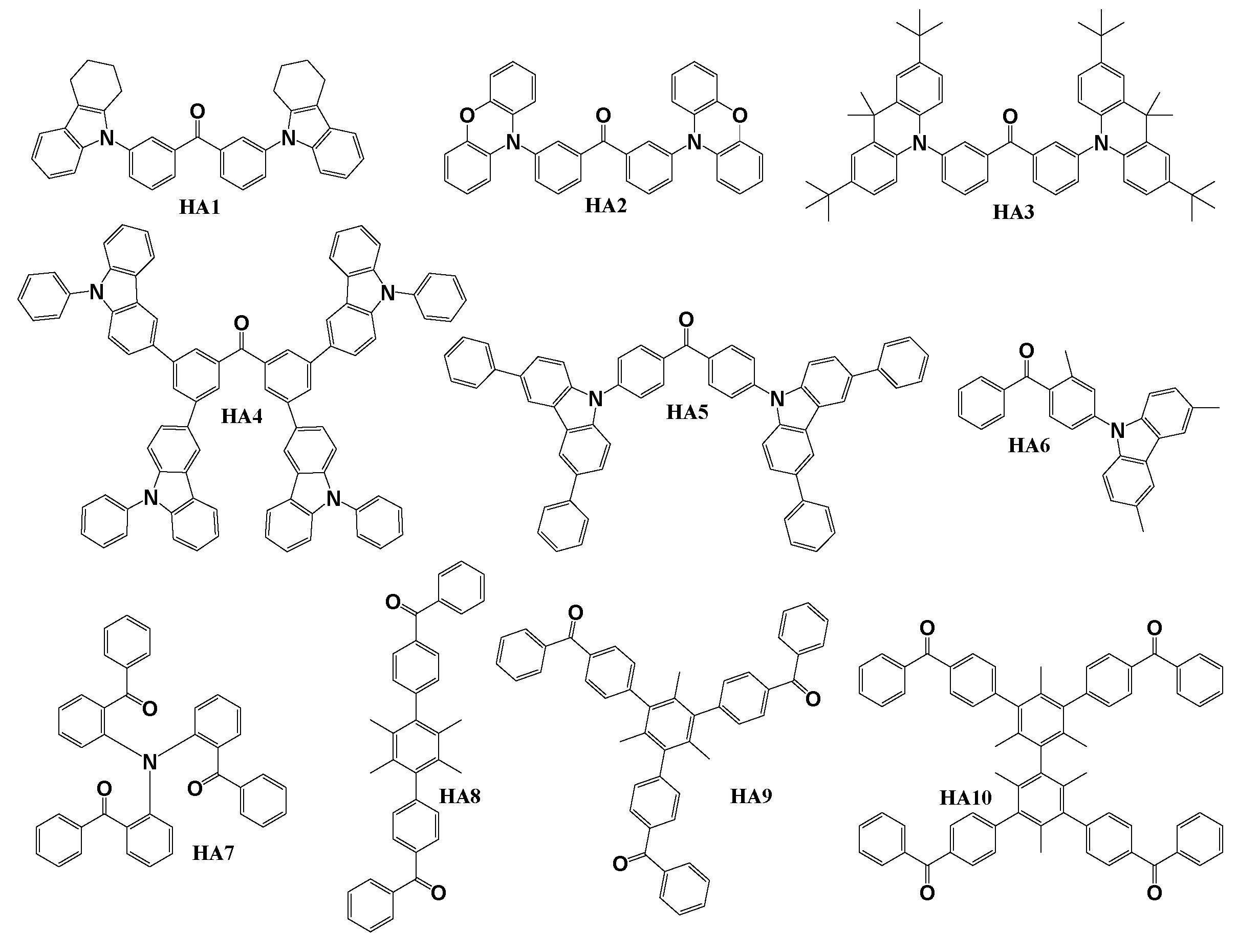
Scheme 2.
Structures of benzophenone-based materials used as hosts in TADF OLEDs.
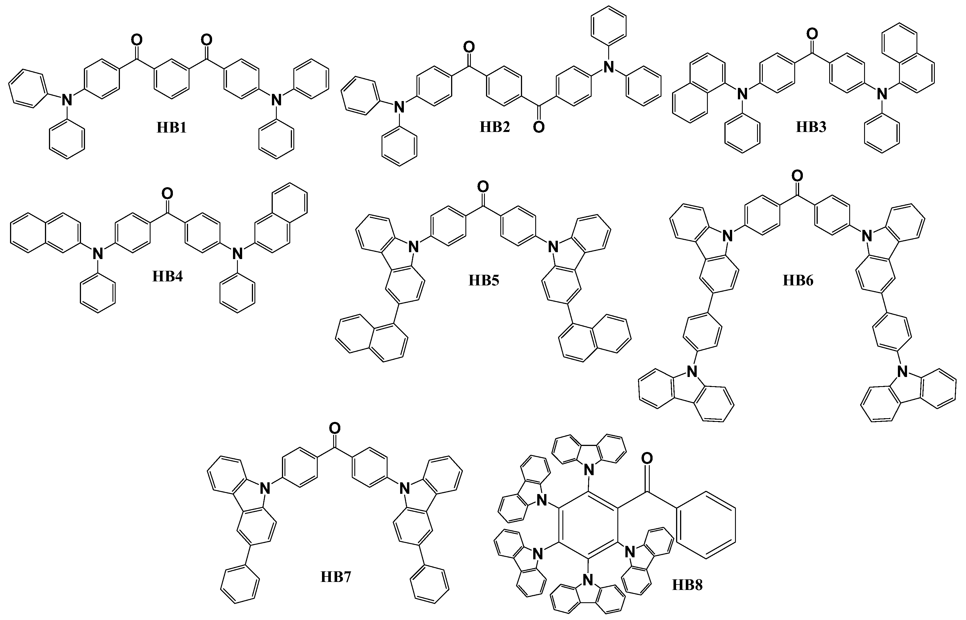
Scheme 3.
Structures of benzophenone-based D-A materials used as emitters in OLEDs.
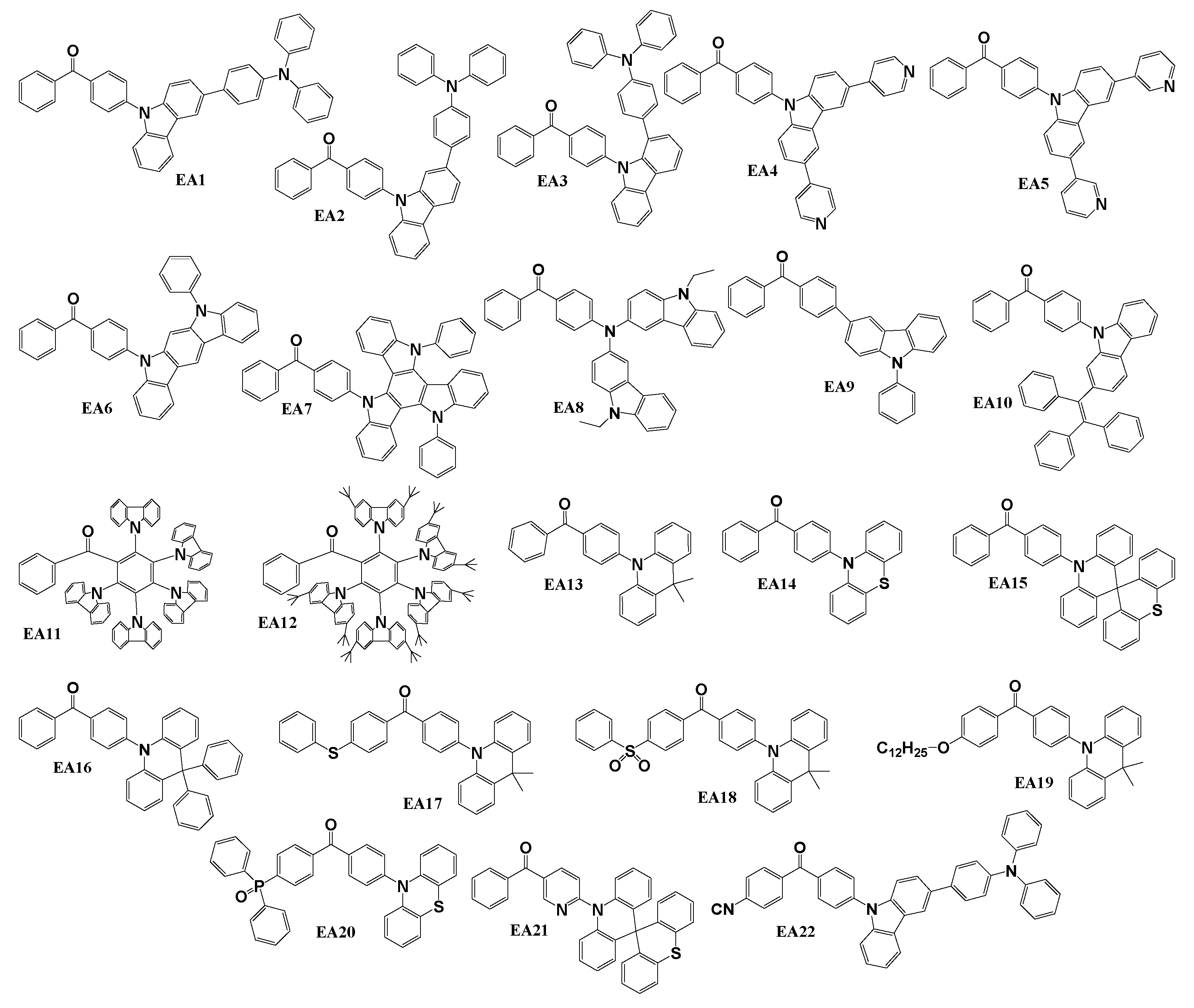
Scheme 4.
Structures of benzophenone-based symmetrical D-A-D materials used as emitters in OLEDs.
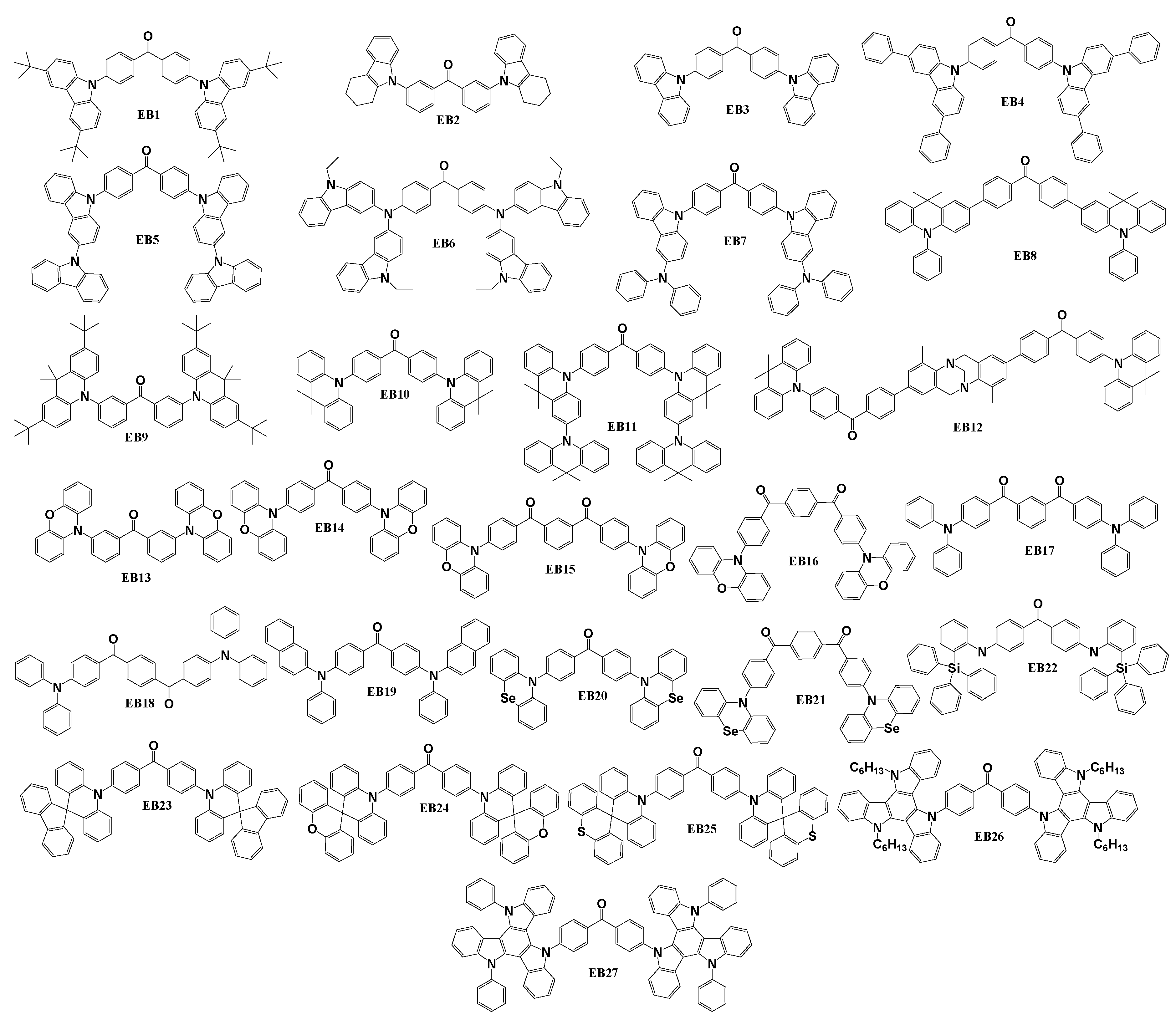
Scheme 5.
Structures of benzophenone-based asymmetrical D-A-D materials used as emitters in OLEDs.
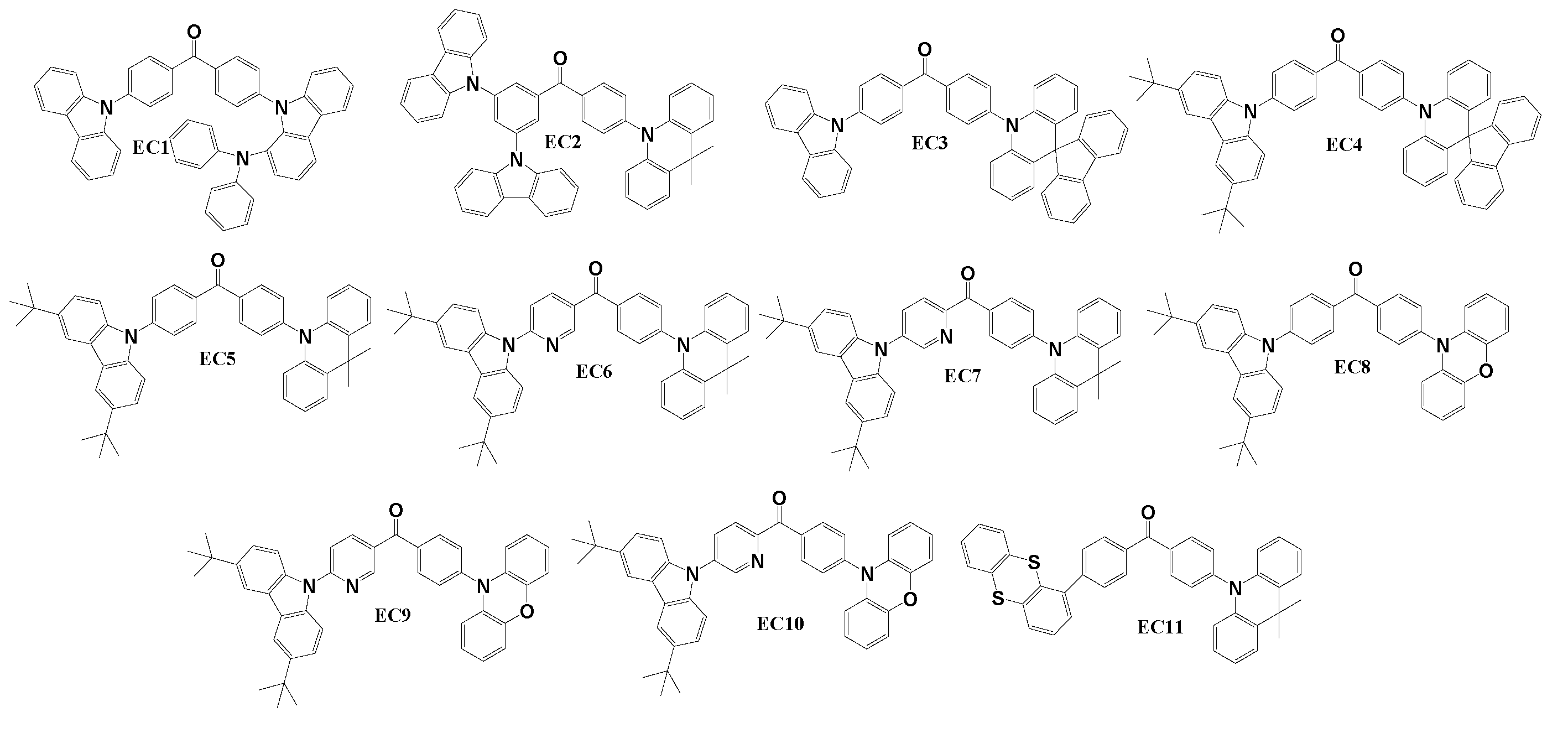
Scheme 6.
Structures of benzophenone-based dendritic materials used as emitters in OLEDs.
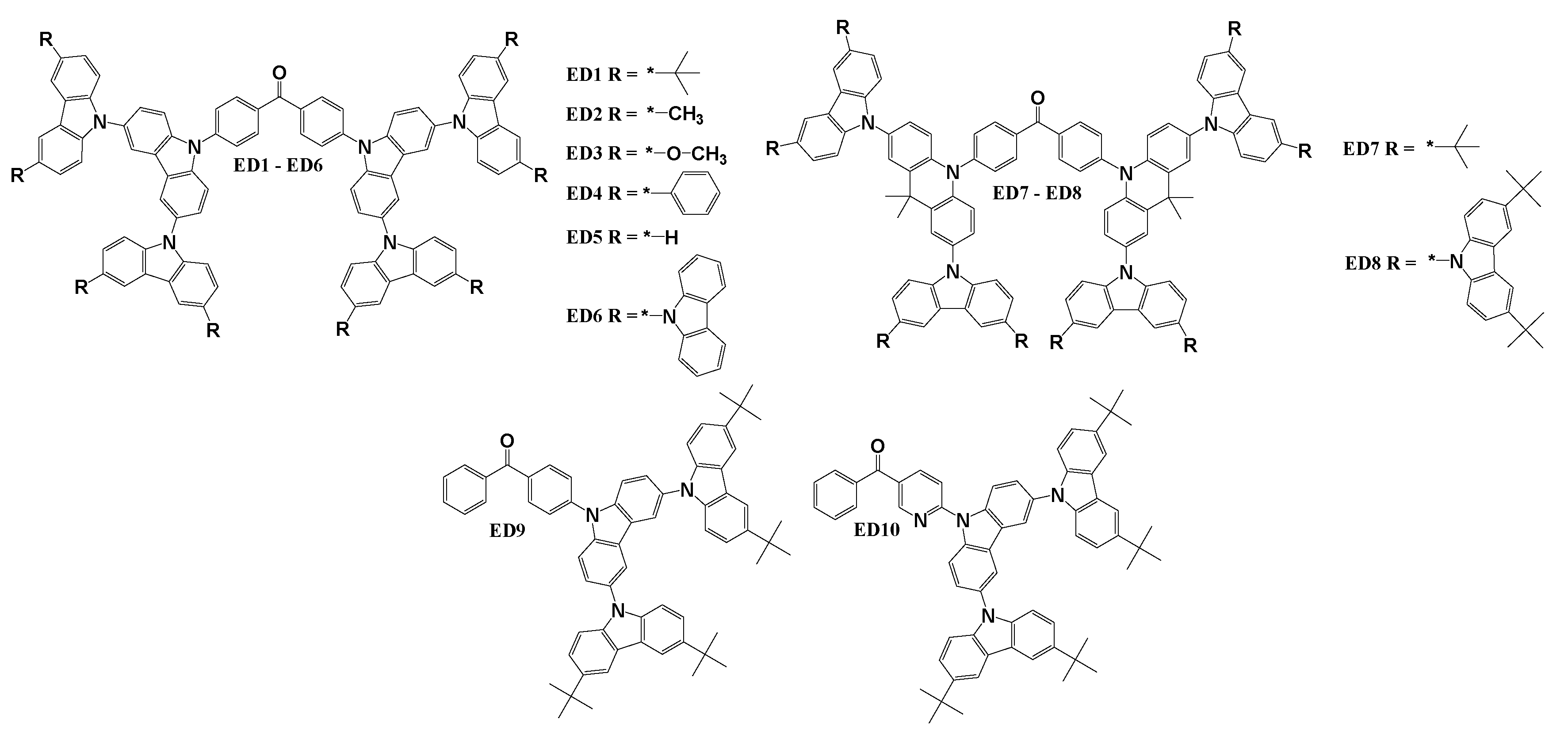
Table 1.1.
Thermal, electrochemical, photoelectrical and photophysical properties of materials HA1 – HA10.
Table 1.1.
Thermal, electrochemical, photoelectrical and photophysical properties of materials HA1 – HA10.
| TM, oC | TG, oC | TCr, oC | TD, oC | Eg, eV | ES, eV | ET, eV | ΔEST, eV | HOMO, eV | LUMO, eV | ΦPL film, % | ΦPL sol., % | |
| HA1 | - | 91 | - | 312 | 3.21 | - | 3.02 | - | -5.17 | -2.03 | 20 | 3 |
| HA2 | 118 | - | 62 | 218 | 3.05 | - | 2.65 | - | -4.74 | -2.19 | 15 | 12 |
| HA3 | 342 | - | 269 | 389 | 3.66 | 2.70 | 2.66 | 0.04 | -4.78 | -2.02 | 16 | 6 |
| HA4 | - | 188 | - | 553 | 3.00 | - | 2.61 | - | -5.80 | -2.80 | - | - |
| HA5 | 370 | - | - | 480 | 3.52 | 2.83 | 2.69 | 0.14 | -5.77 | -2.25 | 24.4 | 15.3 |
| HA6 | - | 131 | - | - | 3.10 | 3.70 | 3.00 | 0.70 | -5.60 | -2.50 | - | - |
| HA7 | - | 55 | - | 339 | 2.72 | 2.77 | 2.53 | 0.24 | -5.51 | -2.79 | - | - |
| HA8 | 272 | - | - | 337 | 3.91 | - | 2.97 | - | -5.80 | -1.89 | - | - |
| HA9 | 291 | - | - | 445 | 3.93 | - | 2.97 | - | -5.76 | -1.83 | - | - |
| HA10 | - | 122 | - | 466 | 3.91 | - | 2.95 | - | -5.78 | -1.87 | - | - |
Table 1.2.
Architectures of devices utilizing host materials HA1 – HA10.
| Device with HA host | Device architecture |
| DHA3 | ITO/TAPC(50 nm)/mCP(10nm)/HA3:7wt% Ir(piq)2acac (30nm)/Bphen(50nm)/LiF(1nm)/Al (100nm) |
| DHA4 | ITO (130nm) / PEDOT:PSS (30nm) /TFB (20nm) / HA4:8wt% Ir(ppy)3 / Cs2CO3:Al (100nm) |
| D1HA5 | ITO/NPB (35nm)/mCP (5nm)/HA5:3wt% Ir(ppy)2acac (30 nm)/B3PYMPM (30nm)/LiF (0.5nm)/Al (150nm) |
| D2HA5 | ITO/NPB (35nm)/mCP 5nm)/HA5:3wt% Ir(bzq)2(dipba) (30 nm)/B3PYMPM (30nm)/LiF (0.5nm)/Al (150nm) |
| D3HA5 | ITO/NPB (35nm)/mCP 5nm)/HA5:3wt% Ir(bt)2(dipba) (30 nm)/B3PYMPM (30nm)/LiF (0.5nm)/Al (150nm) |
| D1HA6 | ITO/TAPC(30nm)/TCTA(10nm)/HA6:FIrpic(20nm)/CzPhPy(10nm)/TmPyPB(45nm)/LiF/Al |
| D2HA6 | ITO/TAPC(30nm)/TCTA(10nm)/HA6:Ir(ppy)2(acac)(20nm)/CzPhPy(10nm)/TmPyPB(45nm)/LiF/Al |
| D3HA6 | ITO/TAPC(30nm)/TCTA(10nm)/HA6:Ir(mphmq)2(tmd)(20nm)/HA8(10nm)/CzPhPy(10nm)/TmPyPB(45nm)/LiF/Al |
| DHA7 | ITO/HAT-CN(10nm)/TAPC(65nm)/TCTA(10nm)/HA7:10wt% Ir(MDQ)2acac(30nm)/TmPyPb(55 nm)/Liq(1nm)/Al(110 nm) |
| D1HA8 | ITO/NPB(40nm)/mCP(10nm)/HA8:9-10wt% Ir(ppy)3(30nm)/TmPyPB(45nm)/LiF(2nm)/Al(150nm) |
| D2HA8 | ITO/NPB(40nm)/mCP(10nm)/HA8:9-10wt% Ir(btp)2acac(30nm)/TmPyPB(45nm)/LiF(2nm)/Al(150nm) |
| D3HA8 | ITO/NPB(40nm)/mCP(10nm)/HA8:9-10wt% FIrpic (30nm)/TmPyPB(45nm)/LiF(2nm)/Al(150nm) |
| D4HA8 | ITO/NPB(40nm)/mCP(10nm)/HA8:9-10wt% PO-01(30nm)/TmPyPB(45nm)/LiF(2nm)/Al(150nm) |
| D1HA9 | ITO/NPB(40nm)/mCP(10nm)/HA9:9-10wt% Ir(ppy)3(30nm)/TmPyPB(45nm)/LiF(2nm)/Al(150nm) |
| D2HA9 | ITO/NPB(40nm)/mCP(10nm)/HA9:9-10wt% Ir(btp)2acac(30nm)/TmPyPB(45nm)/LiF(2nm)/Al(150nm) |
| D3HA9 | ITO/NPB(40nm)/mCP(10nm)/HA9:9-10wt% FIrpic (30nm)/TmPyPB(45nm)/LiF(2nm)/Al(150nm) |
| D4HA9 | ITO/NPB(40nm)/mCP(10nm)/HA9:9-10wt% PO-01(30nm)/TmPyPB(45nm)/LiF(2nm)/Al(150nm) |
| D1HA10 | ITO/NPB(40nm)/mCP(10nm)/HA10:9-10wt% Ir(ppy)3(30nm)/TmPyPB(45nm)/LiF(2nm)/Al(150nm) |
| D2HA10 | ITO/NPB(40nm)/mCP(10nm)/HA10:9-10wt% Ir(btp)2acac(30nm)/TmPyPB(45nm)/LiF(2nm)/Al(150nm) |
| D3HA10 | ITO/NPB(40nm)/mCP(10nm)/HA10:9-10wt% FIrpic (30nm)/TmPyPB(45nm)/LiF(2nm)/Al(150nm) |
| D4HA10 | ITO/NPB(40nm)/mCP(10nm)/HA10:9-10wt% PO-01(30nm)/TmPyPB(45nm)/LiF(2nm)/Al(150nm) |
Table 1.3.
Characteristics of phosphorescent OLED devices using host materials HA1 – HA10.
| Device | Host | Colour | VON, V | LMAX, cd/m2 | CE, cd/A | PE, lm/W | EQE, % | CIE (x, y) |
| DHA3 | HA3 | Red | - | 1094 | 5.6 | 5.30 | 8.60 | (0.68, 0.32) |
| DHA4 | HA4 | Green | - | - | - | 22.0 | 14.6 | - |
| D1HA5 | HA5 | Green | 2.5 | 93330 | - | 99.1 | 25.1 | (0.29, 0.64) |
| D2HA5 | HA5 | Orange | 2.6 | 31200 | - | 61.6 | 23.1 | (0.51, 0.47) |
| D3HA5 | HA5 | Red | 2.9 | 10240 | - | 27.1 | 22.1 | (0.61, 0.36) |
| D1HA6 | HA6 | Blue | 3.0 | - | - | 38.2 | 19.4 | (0.16, 0.33) |
| D2HA6 | HA6 | Green | 2.9 | - | - | 75.7 | 21.0 | (0.29, 0.64) |
| D3HA6 | HA6 | Red | 3.1 | - | - | 30.8 | 16.5 | (0.62, 0.38) |
| DHA7 | HA7 | Red | 4.0 | 3876 | 20.6 | 12.6 | 16.1 | - |
| D1HA8 | HA8 | Green | 4.5 | 3080 | 46.8 | 29.1 | 17.0 | (0.30, 0.60) |
| D2HA8 | HA8 | Red | 5.0 | 905 | 5.5 | 2.2 | 5.9 | (0.65, 0.32) |
| D3HA8 | HA8 | Blue | 5.5 | 708 | 10.9 | 4.6 | 5.3 | (0.17, 0.32) |
| D4HA8 | HA8 | Yellow | 5.5 | 3490 | 50.6 | 28.9 | 19.2 | (0.47, 0.51) |
| D1HA9 | HA9 | Green | 4.5 | 4940 | 45.6 | 31.9 | 15.6 | (0.31, 0.60) |
| D2HA9 | HA9 | Red | 4.5 | 1840 | 13.2 | 9.2 | 10.8 | (0.67, 0.33) |
| D3HA9 | HA9 | Blue | 4.5 | 1010 | 9.3 | 3.7 | 4.5 | (0.17, 0.32) |
| D4HA9 | HA9 | Yellow | 4.5 | 6480 | 50.8 | 31.9 | 18.5 | (0.48, 0.51) |
| D1HA10 | HA10 | Green | 4.5 | 5020 | 37.5 | 26.2 | 12.1 | (0.31, 0.60) |
| D2HA10 | HA10 | Red | 4.0 | 1820 | 19.9 | 15.6 | 13.7 | (0.67, 0.33) |
| D3HA10 | HA10 | Blue | 5.5 | 473 | 8.5 | 4.9 | 4.0 | (0.19, 0.32) |
| D4HA10 | HA10 | Yellow | 4.5 | 10700 | 30.5 | 21.3 | 10.7 | (0.48, 0.52) |
Table 2.1.
Thermal, electrochemical, photoelectrical and photophysical properties of materials HB1 – HB8.
Table 2.1.
Thermal, electrochemical, photoelectrical and photophysical properties of materials HB1 – HB8.
| TM, oC | TG, oC | TCr, oC | TD, oC | Eg, eV | ES, eV | ET, eV | ΔEST, eV | HOMO, eV | LUMO, eV | ΦPL film, % | ΦPL sol., % | ||
| N2 | O2 | ||||||||||||
| HB1 | - | 90 | - | 436 | 2.84 | 2.59 | 2.38 | 0.21 | -5.31 | -2.47 | 75 | 46 | |
| HB2 | - | 92 | - | 416 | 2.70 | 2.37 | 2.32 | 0.05 | -5.32 | -2.62 | 2 | 2 | |
| HB3 | 218 | 101 | 203 | 411 | 2.89 | 3.07 | 2.55 | 0.52 | -5.13 | -1.47 | 9 | 9 | |
| HB4 | 241 | 107 | - | 428 | 2.78 | 3.00 | 2.53 | 0.47 | -5.08 | -1.53 | 13 | 13 | |
| HB5 | - | 156 | - | - | 3.33 | 2.91 | 2.61 | 0.30 | -5.38 | -2.05 | |||
| HB6 | 123 | 92 | - | 277 | 4.10 | 2.97 | 2.64 | 0.33 | -6.15 | -2.63 | |||
| HB7 | 366 | 187 | - | 371 | 4.00 | 2.95 | 2.60 | 0.35 | -6.05 | -2.45 | |||
| HB8 | - | - | - | 497 | 2.80 | 2.61 | 2.60 | 0.01 | -5.35 | -2.55 | 8 | 6 | |
Table 2.2.
Architectures of devices utilizing host materials HB1 – HB8.
| Device | Device architecture |
| DHB1 | ITO/PEDOT:PSS(40nm)/HB1:10wt% 4CzCNPy(35-40nm)/TmPyPB(60nm)/LiF(0.8nm)/Al(120 nm) |
| DHB2 | ITO/PEDOT:PSS(40nm)/HB2:10wt% 4CzCNPy(35-40nm)/TmPyPB(60nm)/LiF(0.8nm)/Al(120 nm) |
| DHB3 | ITO/MoO3(8nm)/NPB(60nm)/TAPC(5nm)/HB3:5wt% 4CzTPN(5nm)/HB3(15nm)/PFBP-2b(20 wt%):TPBi(40nm)/LiF(1nm)/Al |
| DHB4 | ITO/MoO3(8nm)/NPB(60nm)/TAPC(5nm)/HB4:5wt% 4CzTPN(5nm)/HB4(15nm)/PFBP-2b(20 wt%):TPBi(40nm)/LiF(1nm)/Al |
| DHB5 | ITO(125 nm)/PEDOT:PSS(30nm)/HB5:15wt% 4CzIPN(20nm)/TPBi(30nm)/LiF(1.0nm)/Al(150 nm) |
| D1HB6 | ITO(125 nm)/PEDOT:PSS(35 nm)/HB6:4CzIPN(20 nm)/PO-T2T(10 nm)/TPBi(30 nm)/LiF(1nm)/Al(200 nm) |
| D2HB6 | ITO(125 nm)/PEDOT:PSS(35 nm)/VPEC(10nm)/HB6:4CzIPN(20 nm)/PO-T2T(10 nm)/TPBi(30 nm)/LiF(1nm)/Al(200 nm) |
| DHB7 | ITO(125 nm)/PEDOT:PSS(35 nm)/HB7:4CzIPN(20 nm)/PO-T2T(10 nm)/TPBi(30 nm)/LiF(1nm)/Al(200 nm) |
| DHB8 | ITO/PEDOT:PSS(40nm)/HB8:10wt% 4CzCNPy(40nm)/TmPyPB(60nm)/LiF(0.8nm)/Al (100 nm) |
Table 2.3.
Characteristics of TADF OLED devices using host materials HB1 – HB8.
| Device | Host | Colour | VON, V | LMAX, cd/m2 | CE, cd/A | PE, lm/W | EQE, % | CIE (x, y) |
| DHB1 | HB1 | Green | 3.5 | 20322 | 43.5 | 33.3 | 13.0 | (0.32, 0.60) |
| DHB2 | HB2 | Green | 3.2 | 15510 | 29.3 | 25.4 | 9.0 | (0.33, 0.58) |
| DHB3 | HB3 | White | 3.9 | 29922 | 18.6 | - | 9.5 | (0.36, 0.31) |
| DHB4 | HB4 | White | 3.6 | 15350 | 13.8 | - | 7.1 | (0.32, 0.31) |
| DHB5 | HB5 | Green | 3.4 | 8601 | 9.5 | 8.4 | 2.8 | (0.31, 0.59) |
| D1HB6 | HB6 | Green | 3.0 | 16500 | 70.7 | 55.6 | 23.2 | (0.28, 0.57) |
| D2HB6 | HB6 | Green | 2.9 | 18900 | 72.3 | 63.6 | 25.3 | (0.29, 0.58) |
| DHB7 | HB7 | Green | 2.7 | 10540 | 49.2 | 46.2 | 15.3 | (0.28, 0.57) |
| DHB8 | HB8 | Green | 3.7 | 22004 | 38.3 | - | 12.5 | (0.34, 0.58) |
Table 3.1.
Thermal, electrochemical, photoelectrical and photophysical properties of materials EA1 – EA22.
Table 3.1.
Thermal, electrochemical, photoelectrical and photophysical properties of materials EA1 – EA22.
| TM, oC | TG, oC | TD, oC | Eg, eV | ES, eV | ET, eV | ΔEST, eV | HOMO, eV | LUMO, eV | ΦPL film, % | ΦPL sol., % | RD,% | |||
| N2 | O2 | N2 | O2 | |||||||||||
| EA1 | - | 90 | 367 | 2.39 | 2.81 | 2.55 | 0.26 | -5.55 | -3.16 | 42.0 | 12.4 | |||
| EA2 | - | 148 | 377 | 2.43 | 2.81 | 2.44 | 0.37 | -5.58 | -3.15 | 20.0 | ||||
| EA3 | - | - | 407 | 2.33 | 2.78 | 2.76 | 0.02 | -5.51 | -3.18 | 50.0 | ||||
| EA4 | - | - | - | 3.94 | 0.06 | -5.83 | -1.89 | 23.4 | 19.1 | 56.0 | 18.0 | |||
| EA5 | - | - | - | 4.02 | 0.07 | -5.99 | -1.97 | 21.0 | 17.3 | 52.0 | 10.0 | |||
| EA6 | - | 177 | 278 | 3.00 | 2.92 | 2.83 | 0.09 | -5.45 | -2.45 | 62.0 | 37.9 | |||
| EA7 | - | 145 | 379 | 2.72 | 2.68 | 2.59 | 0.06 | -5.37 | -2.65 | 51.0 | 14.0 | |||
| EA8 | 135 | - | - | 2.60 | 0.24 | -5.20 | -2.60 | 76.0 | 70 | |||||
| EA9 | - | 155 | 311 | 3.09 | 2.97 | 2.55 | 0.42 | -5.66 | -2.57 | 50.8 | ||||
| EA10 | 200 | 107 | 341 | - | 3.66 | 2.57 | 1.09 | |||||||
| EA11 | - | - | 497 | 2.80 | 2.61 | 2.60 | 0.01 | -5.35 | -2.55 | 24.0 | 8.0 | 6.0 | ||
| EA12 | - | 194 | 420 | 2.80 | 2.86 | 2.76 | 0.10 | -5.90 | -3.10 | 28.0 | 8.4 | |||
| EA13 | - | - | 297 | 2.87 | 2.90 | 2.81 | 0.09 | -5.06 | -2.19 | 75.0 | 81.3 | |||
| EA14 | - | - | - | 2.60 | 0.07 | 31.0 | ||||||||
| EA15 | - | 165 | 372 | 2.91 | 0.09 | -5.11 | -1.98 | 75.7 | 66.3 | |||||
| EA16 | - | - | - | 2.64 | 2.14 | 2.13 | 0.01 | -5.70 | -3.06 | 47.0 | 70.2 | |||
| EA17 | - | - | 367 | 2.31 | 2.64 | 2.63 | 0.008 | -5.24 | -2.93 | 90.1 | ||||
| EA18 | - | 80 | 350 | 2.01 | 2.03 | 2.02 | 0.005 | -5.24 | -3.23 | 39.7 | ||||
| EA19 | - | - | 355 | 3.20 | 2.64 | 2.63 | 0.01 | -4.93 | -1.73 | |||||
| EA20 | - | 91 | 428 | 2.3 | 2.61 | 2.59 | 0.02 | -5.50 | -3.20 | |||||
| EA21 | - | 102 | 389 | 2.81 | 0.08 | -5.12 | -2.22 | 98.9 | 60.1 | |||||
| EA22 | - | - | 460 | 2.07 | 2.56 | 2.47 | 0.09 | -5.02 | -2.95 | 63.0 | 41.0 | |||
Table 3.2.
Architectures of devices utilizing the emitters EA1 – EA22.
| Device | Device architecture |
| DEA1 | ITO/PEDOT:PSS (40 nm)/EA1(40nm)/TPBi(30nm)/Cs2CO3(2nm)/Al(100nm) |
| DEA2 | ITO/PEDOT:PSS (40 nm)/EA2(40nm)/TPBi(30nm)/Cs2CO3(2nm)/Al(100nm) |
| DEA3 | ITO/PEDOT:PSS (40 nm)/EA3(40nm)/TPBi(30nm)/Cs2CO3(2nm)/Al(100nm) |
| DEA4 | ITO/NPB(30nm)/TAPC(20 nm)/mCP(10nm)/DPEPO:7wt.% EA4(30nm)/TPBi(40nm)/LiF(0.8nm)/Al(100 nm) |
| DEA5 | ITO/NPB(30nm)/TAPC(20 nm)/mCP(10nm)/DPEPO:7wt.% EA5(30nm)/TPBi(40nm)/LiF(0.8nm)/Al(100 nm) |
| DEA6 | ITO/HAT-CN(10nm)/TAPC(30nm)/TCTA(10nm)/DPEPO:10wt.% EA6(40nm)/TmPyPB(40nm)/LiF(1nm)/Al(100nm) |
| DEA7 | ITO/PEDOT:PSS(25nm)/EA7(25nm)/TmPyPB(55nm)/LiF(1nm)/Al(150nm) |
| DEA8 | ITO(50nm)/PEDOT:PSS(30 40 nm)/TCzl:5 wt%EA8/TPBi(50nm)/Liq(1nm)/Al(80nm) |
| DEA9 | ITO/TAPC(40nm)/TCTA(20nm)/EA9(40nm)/TmPyPB(50nm)/LiF(1nm)/Al(100nm) |
| DEA10 | ITO(120nm)/TAPC:20wt%MoO3(20nm)/TAPC(20nm)/TCTA(10nm)/EA10(20nm)/CBP(2nm)/TmPyPB(50nm)/LiF (1.2 nm)/Al (120 nm) |
| DEA11 | ITO/PEDOT:PSS(40nm)/mCP:10 wt%EA11(40nm)/TmPyPB(60nm)/LiF(0.8nm)/Al(100nm) |
| D1EA12 | ITO/NPB(30nm)/TCTA(20nm)/CzSi(10nm)/EA12(20nm)/DPEPO(10nm)/TPBi(30nm)/LiF(1nm)/Al100 nm) |
| D2EA12 | ITO/NPB(30nm)/TCTA(20nm)/CzSi(10nm)/DPEPO:20wt%EA12(20nm)/DPEPO(10nm)/TPBi(30nm)/LiF(1nm)/Al(100 nm) |
| D1EA13 | ITO/MoO3(1nm)/TAPC(50nm)/mCP(10nm)/EA13(30nm)/DPEPO(10nm)/TmPyPB(30nm)/LiF(1nm)/Al(100 nm) |
| D2EA13 | ITO/MoO3(1nm)/TAPC(50nm)/mCP(10nm)/BCPO:20wt%EA13(30nm)/DPEPO(10nm)/TmPyPB(30nm)/LiF(1nm)/Al(100 nm) |
| DEA14 | ITO(100nm)/α-NPD(40 nm)/mCBP (10nm)/EA14(15nm)/B3PyPB(55nm)/Liq(1nm)/Al(80nm) |
| D1EA15 | ITO/TAPC(30nm)/mCP(10nm)/EA15(20nm)/DPEPO(10nm)/TmPyPB(40nm)/LiF/Al |
| D2EA15 | ITO/TAPC(30nm)/mCP(10nm)/DPEPO:30wt%EA15(20nm)/DPEPO(10nm)/TmPyPB(40nm)/LiF/Al |
| DEA16 | ITO/TAPC(40nm)/TCTA(10nm)/mCP(10nm)/EA16/TmPyPb(40nm)/LiF(1nm)/Al(120nm) |
| D1EA17 | ITO/PEDOT:PSS(40nm)/TAPC(20nm)/EA17(20nm)/TmPyPB(40nm)/LiF(1nm)/Al (200nm) |
| D2EA17 | ITO/PEDOT:PSS(40nm)/TAPC(20nm)/CBP:5 wt% EA17(20nm)/TmPyPB(40nm)/LiF(1nm)/Al (200nm) |
| D1EA18 | ITO/PEDOT:PSS(40nm)/TAPC(20nm)/EA18(20nm)/TmPyPB(40nm)/LiF(1nm)/Al (200nm) |
| D2EA18 | ITO/PEDOT:PSS(40nm)/TAPC(20nm)/CBP:5 wt% EA18(20nm)/TmPyPB(40nm)/LiF(1nm)/Al (200nm) |
| DEA19 | ITO/PEDOT:PSS(30nm)/mCP:CzAcSF:EA19(40:30:30)(40nm)/DPEPO(10 nm)/TmPyPB(50nm)/Liq(1nm)/Al(100nm) |
| D1EA20 | ITO/PEDOT:PSS(40 nm)/CBP(20nm)/CBP:10wt%EA20(15nm)/TPBI(40 nm)/Mg:Ag |
| D2EA20 | ITO/PEDOT:PSS(40nm)/CBP(20nm)/EA20(4nm)/2CzTPEPCz(15nm)/TPBI(40nm)/Mg:Ag |
| D1EA21 | ITO/TAPC(30nm)/mCP(10nm)/EA21(20nm)/DPEPO(10nm)/TmPyPB(40nm)/LiF/Al |
| D2EA21 | ITO/TAPC(30nm)/mCP(10nm)/DPEPO:30wt%EA21(20nm)/DPEPO(10nm)/TmPyPB(40nm)/LiF/Al |
| DEA22 | ITO/TAPC(30nm)/TCTA(10nm)/mCP:5 wt%EA22(20nm)/TmPyPb(40nm)/LiF(1nm)/Al |
Table 3.3.
Characteristics of OLED devices using emitters EA1 – EA22.
| Device | Emitter | Colour | VON, V | LMAX, cd/m2 | CE, cd/A | PE, lm/W | EQE, % | CIE (x, y) |
| DEA1 | EA1 | Green | 3.9 | 615 | 8.00 | 4.20 | 3.40 | (0.27, 0.43) |
| DEA2 | EA2 | Blue | 4.4 | 568 | 3.90 | 1.70 | 1.80 | (0.21, 0.29) |
| DEA3 | EA3 | Green | 3.8 | 1472 | 17.9 | 11.2 | 7.60 | (0.26, 0.42) |
| DEA4 | EA4 | Blue | 5.5 | 663 | 7.30 | 4.20 | 5.00 | (0.18, 0.21) |
| DEA5 | EA5 | Blue | 6.0 | 605 | 3.10 | 1.60 | 2.10 | (0.19, 0.22) |
| DEA6 | EA6 | Blue | 3.2 | 14724 | 44.8 | 45.6 | 17.7 | (0.17, 0.28) |
| DEA7 | EA7 | Green | 2.5 | >10000 | 20.9 | 21.8 | 6.40 | - |
| DEA8 | EA8 | Green | - | - | - | - | 6.90 | - |
| DEA9 | EA9 | Blue | 4.0 | 10754 | 23.3 | 19.3 | 9.50 | (0.15, 0.15) |
| DEA10 | EA10 | Green | 3.1 | 11802 | 4.10 | 3.60 | 1.70 | (0.23, 0.37) |
| DEA11 | EA11 | Green | 4.7 | 17353 | 24.8 | - | 8.90 | (0.25, 0.48) |
| D1EA12 | EA12 | Green | 3.8 | 2544 | 19.0 | 14.9 | 10.3 | (0.26, 0.47) |
| D2EA12 | EA12 | Green | 4.1 | 568 | 34.9 | 27.3 | 12.5 | (0.23, 0.41) |
| D1EA13 | EA13 | Green | 3.9 | 3006 | 18.2 | 14.1 | 6.59 | (0.26, 0.47) |
| D2EA13 | EA13 | Green | 3.2 | 13280 | 44.4 | 45.0 | 15.2 | (0.27, 0.50) |
| DEA14 | EA14 | Yellow | - | - | - | - | 7.60 | - |
| D1EA15 | EA15 | Green | 3.2 | 6823 | 34.7 | 30.1 | 14.2 | (0.20, 0,39) |
| D2EA15 | EA15 | Green | 3.2 | 15047 | 53.4 | 48.8 | 21.2 | (0.21, 0.42) |
| DEA16 | EA16 | Green | 3.0 | - | 32.7 | 34.3 | 12.9 | (0.21, 0.42) |
| D1EA17 | EA17 | Green | 2.5 | 21243 | 53.7 | 52.7 | 17.3 | (0.31, 0.54) |
| D2EA17 | EA17 | Green | 3.2 | 11977 | 49.6 | 48.6 | 17.7 | (0.24, 0.49) |
| D1EA18 | EA18 | Yellow | 2.5 | 11949 | 8.90 | 7.99 | 3.35 | (0.48, 0.50) |
| D2EA18 | EA18 | Green | 2.7 | 31115 | 64.6 | 75.1 | 20.6 | (0.37, 0.55) |
| DEA19 | EA19 | Blue | 4.0 | 4235 | 47.7 | 29.9 | 20.6 | - |
| D1EA20 | EA20 | Yellow | 4.4 | 32590 | 73.1 | 38.2 | 26.7 | - |
| D2EA20 | EA20:2CzTPEPCz | White | 6.1 | 12310 | 45.9 | 18.0 | 20.8 | (0.45, 0.44) |
| D1EA21 | EA21 | Green | 3.2 | 26836 | 56.4 | 43.5 | 18.7 | (0.28, 0.53) |
| D2EA21 | EA21 | Green | 3.2 | 11392 | 69.8 | 58.9 | 25.6 | (0.24, 0.49) |
| DEA22 | EA22 | Green | 3.3 | - | 48.4 | 46.1 | 15.6 | - |
Table 4.1.
Thermal, electrochemical and photo-physical properties of materials EB1 – EB27.
| TM, oC | TG, oC | TCr, oC | TD, oC | Eg, eV | ES, eV | ET, eV | ΔEST, eV | HOMO, eV | LUMO, eV | ΦPL film, % | ΦPL sol., % | RD,% | ||
| N2 | O2 | |||||||||||||
| EB1 | - | 107 | - | 384 | 2.95 | 2.62 | 2.47 | 0.15 | -5.16 | -2.21 | 13.1 | 2.20 | 87.8 | |
| EB2 | - | 91 | - | 312 | 3.21 | 3.02 | -5.17 | -2.03 | 20.0 | 3.00 | ||||
| EB3 | 3.10 | 2.89 | 3.10 | 0.21 | -5.74 | -2.64 | 55.0 | 21.0 | ||||||
| EB4 | 370 | - | - | 480 | 3.30 | 2.83 | 2.69 | 0.14 | -5.77 | -2.25 | 24.4 | 15.3 | ||
| EB5 | 3.02 | 3.02 | 2.88 | 0.14 | -5.65 | -2.63 | 73.0 | 38.0 | ||||||
| EB6 | 2.60 | 0.29 | -5.10 | -2.50 | 73.0 | 37.0 | ||||||||
| EB7 | - | 159 | - | 398 | 2.79 | -5.58 | -2.79 | |||||||
| EB8 | 0.39 | 53.0 | 7.5 | |||||||||||
| EB9 | 342 | - | 269 | 389 | 3.66 | 2.70 | 2.66 | 0.04 | -4.78 | -2.19 | 16.0 | 6.00 | ||
| EB10 | 410 | 2.76 | 2.69 | 0.07 | 90.0 | |||||||||
| EB11 | - | - | - | 433 | 2.82 | 0.03 | -5.16 | - 2.34 | 89.1 | |||||
| EB12 | 270 | 2.86 | 2.81 | 2.68 | 0.13 | -5.26 | -2.40 | 31.5 | 32.7 | |||||
| EB13 | 118 | - | 62 | 218 | 3.05 | 2.65 | -4.74 | -2.19 | 15.0 | 12.0 | ||||
| EB14 | 2.52 | 2.61 | 2.58 | 0.03 | -5.44 | -2.92 | 70.0 | 44.0 | ||||||
| EB15 | 2.61 | 2.62 | 2.52 | 0.10 | -5.64 | -3.03 | 71.0 | 36.0 | ||||||
| EB16 | 2.49 | 2.59 | 2.53 | 0.06 | -5.62 | -3.13 | 36.0 | 10.0 | ||||||
| EB17 | - | 90 | - | 436 | 2.84 | 2.59 | 2.38 | 0.21 | -5.31 | -2.47 | 75.0 | 46.0 | ||
| EB18 | - | 92 | - | 416 | 2.70 | 2.37 | 2.32 | 0.05 | -5.32 | -2.62 | 39.0 | 2.00 | ||
| EB19 | - | 99 | - | 440 | 2.90 | 2.66 | 2.47 | 0.19 | -5.51 | -2.60 | 16.3 | |||
| EB20 | 2.84 | 2.69 | 0.15 | 7.60 | ||||||||||
| EB21 | 2.84 | 2.69 | 0.15 | 8.50 | ||||||||||
| EB22 | 300 | - | - | 495 | 2.94 | 2.71 | 2.64 | 0.07 | -5.49 | -2.55 | 70.0 | |||
| EB23 | 445 | 3.37 | 2.62 | 2.61 | 0.01 | -5.42 | -2.05 | 91.0 | 55.6 | |||||
| EB24 | 477 | 3.32 | 2.64 | 2.63 | 0.01 | -5.42 | -2.10 | 94.0 | 54.5 | |||||
| EB25 | 500 | 3.32 | 2.64 | 2.63 | 0.01 | -5.43 | -2.11 | 85.0 | 42.8 | |||||
| EB26 | >95 | >400 | 2.47 | 2.55 | 2.47 | 0.13 | -5.30 | -2.83 | 22.0 | 0.80 | ||||
| EB27 | >95 | >400 | 2.59 | 2.58 | 2.48 | 0.13 | -5.33 | -2.77 | 24.2 | 1.90 | ||||
Table 4.2.
Architectures of devices utilizing the D-A-D emitters EB1 – EB27.
| Device with EB emitter | Device architecture |
| DEB3 | ITO/α-NPD(35nm)/mCP(5nm)/DPEPO:6 wt%EB3(20nm)/DPEPO(10nm)/TPBi(30nm)/LiF(0.8nm)/Al(80 nm) |
| D1EB4 | ITO/NPB(35nm)/mCP(5nm)/EB4(30 nm)/B3PYMPM(30nm)/LiF (0.5 nm)/Al (150 nm) |
| D2EB4 | ITO/NPB(35nm)/mCP(5nm)/EB4:0.5%wt Ir(ppy)2(acac)/EB4:0.8wt% Ir(bt)2(dipba)(30nm)/B3PYMPM(30nm)/LiF(0.5nm)/Al(150nm) |
| DEB5 | ITO/α-NPD(35nm)/mCP(5nm)/DPEPO:6 wt%EB5(20nm)/DPEPO(10nm)/TPBi(30nm)/LiF(0.8nm)/Al(80 nm) |
| DEB6 | ITO(50nm)/PEDOT:PSS(30 40 nm)/TCzl:15 wt%EB6/TPBi(70nm)/Liq(1nm)/Al(80nm) |
| DEB8 | ITO/TAPC(25nm)/CBP:3 wt% EB8(35nm)/TmPyPB(55nm)/LiF(1nm)/Al |
| DEB9 | ITO/TAPC(50 nm)/mCP(10nm)/EB9(30nm)/Bphen(50nm)/LiF(1nm)/Al (100nm) |
| DEB10 | ITO/MoO3(1nm)/mCP(40nm)/EB10(30nm)/TBPi(50nm)/LiF(1nm)/Al |
| DEB11 | ITO/PEDOT:PSS(40nm)/mCPCN:25wt% EB11 (45nm)/DPEPO(10nm)/TmPyPB(40nm)/Liq(1.2nm)/Al(120nm) |
| DEB12 | ITO/HAT-CN(5nm)/TAPC(30nm)/TCTA(5nm)/mCP(5nm)/PPF:20% EB12(30nm)/PPF(10nm)/Bphen(30nm)/Liq(1nm)/Al(100nm) |
| DEB14 | ITO/α-NPD(40nm)/mCP:6 wt%EB14(20nm)/TPBi(40nm)/LiF(0.8 nm)/Al(80nm) |
| DEB15 | ITO/α-NPD(40nm)/EB15(20nm)/TPBi(40nm)/LiF(0.8 nm)/Al(80nm) |
| DEB16 | ITO/α-NPD(40nm)/mCBP:6 wt%EB16(20nm)/TPBi(40nm)/LiF(0.8 nm)/Al(80nm) |
| DEB16EB5 | ITO/α-NPD(35nm)/mCBP:18wt%EB16(4nm)/PPF:6wt%EB5(14nm)/PPF(40nm)/LiF(0.8nm)/Al(80nm) |
| DEB17 | ITO/PEDOT:PSS(40nm)/EB17(35-40 nm)/TmPyPB(60nm)/LiF(0.8nm)/Al(120nm) |
| DEB18 | ITO/PEDOT:PSS(40nm)/EB18(35-40 nm)/TmPyPB(60nm)/LiF(0.8nm)/Al(120nm) |
| DEB19 | ITO/Mo2O3(4nm)/mCP(30nm)/mCP:15wt% EB19(30nm)/TmTyPB(60nm)/LiF(1.5nm)/Al(100nm) |
| DEB20 | ITO/α-NPD(40 nm)/mCBP:10wt%EB20(20nm)/TPBi(40nm)/LiF(0.6 nm) /Al(100 nm) |
| DEB21 | ITO/α-NPD(40 nm)/mCBP:10wt%EB21(20nm)/TPBi(40nm)/LiF(0.6 nm) /Al(100 nm) |
| DEB22 | ITO(70nm)/4wt%ReO3:mCP(45nm)/mCP(15nm)/mCP:TSPO1:16wt%EB22(15nm)/TSPO1(15nm)/4wt%Rb2CO3:TSPO1(50nm)/Al(100nm) |
| D1EB23 | ITO/HAT-CN(5nm)/NPB(30nm)/mCP(5nm)/EB23(20 nm)/PPF(5nm)/TPBi(50nm)/LiF(1nm)/Al(120nm) |
| D2EB23 | ITO/HAT-CN(5nm)/NPB(30nm)/mCP(5nm)/PPF:30wt%EB23(20 nm)/PPF(5nm)/TPBi(50nm)/LiF(1nm)/Al(120nm) |
| D1EB24 | ITO/HAT-CN(5nm)/NPB(30nm)/mCP(5nm)/EB24(20 nm)/PPF(5nm)/TPBi(50nm)/LiF(1nm)/Al(120nm) |
| D2EB24 | ITO/HAT-CN(5nm)/NPB(30nm)/mCP(5nm)/PPF:30wt%EB24(20 nm)/PPF(5nm)/TPBi(50nm)/LiF(1nm)/Al(120nm) |
| D1EB25 | ITO/HAT-CN(5nm)/NPB(30nm)/mCP(5nm)/EB25(20 nm)/PPF(5nm)/TPBi(50nm)/LiF(1nm)/Al(120nm) |
| D2EB25 | ITO/HAT-CN(5nm)/NPB(30nm)/mCP(5nm)/PPF:30wt%EB25(20 nm)/PPF(5nm)/TPBi(50nm)/LiF(1nm)/Al(120nm) |
| D1EB26 | ITO/PEDOT:PSS (25 nm)/EB26(25 nm)/TmPyPB (55 nm)/LiF (1 nm)/Al (150 nm) |
| D2EB26 | ITO/PEDOT:PSS (25 nm)/G3-tCbz:30wt%EB26(25 nm)/TmPyPB (55 nm)/LiF (1 nm)/Al (150 nm) |
| D1EB27 | ITO/PEDOT:PSS (25 nm)/EB27(25 nm)/TmPyPB (55 nm)/LiF (1 nm)/Al (150 nm) |
| D1EB27 | ITO/PEDOT:PSS (25 nm)/G3-tCbz:30wt%EB27(25 nm)/TmPyPB (55 nm)/LiF (1 nm)/Al (150 nm) |
Table 4.3.
Characteristics of OLED devices using emitters EB1 – EB27.
| Device | Emitter | Colour | VON, V | LMAX, cd/m2 | CE, cd/A | PE, lm/W | EQE, % | CIE (x, y) |
| DEB3 | EB3 | Blue | 4.3 | 510 | 9.30 | - | 8.10 | (0.16, 0.14) |
| D1EB4 | EB4 | Blue | 3.2 | 5516 | - | 6.90 | 4.00 | (0.15, 0.26) |
| D2EB4 | EB4/Ir(ppy)2(acac)/ Ir(bt)2(dipba) | White | 2.7 | 25540 | 48.6 | - | 25.6 | (0.41, 0.46) |
| DEB5 | EB5 | Blue | 4.4 | 3900 | 25.5 | - | 14.3 | (0.17, 0.27) |
| DEB6 | EB6 | Green | - | - | - | - | 10.4 | - |
| DEB8 | EB8 | Blue | 8.90 | (0.14, 0.16) | ||||
| DEB9 | EB9 | Green | 7.5 | 114 | 11.8 | 9.30 | 1.93 | (0.37, 0.57) |
| DEB10 | EB10 | Green | 2.6 | 45300 | 59.0 | 18.0 | (0.26, 0.55) | |
| DEB11 | EB11 | Green | 4.4 | 7173 | 69.3 | 22.5 | (0.29, 0.54) | |
| DEB12 | EB12 | Green | 5.3 | 3524 | 11.0 | 6.90 | 3.90 | (0.28, 0.51) |
| DEB14 | EB14 | Green | 3.2 | 86100 | 35.9 | - | 10.7 | (0.37, 0.58) |
| DEB15 | EB15 | Red | 2.8 | 50820 | 11.1 | - | 4.20 | (0.58, 0.36) |
| DEB16 | EB16 | Yellow | 3.6 | 57120 | 20.1 | - | 6.90 | (0.49, 0.51) |
| DEB16/EB5 | EB16/EB5 | White | 5.0 | 9800 | 16.4 | - | 6.70 | (0.32, 0,39) |
| DEB17 | EB17 | Blue | 3.9 | 10005 | 4.80 | 2.70 | 2.40 | (0.15, 0.28) |
| DEB18 | EB18 | Green | 3.8 | 7354 | 10.8 | 4.70 | 2.70 | (0.33, 0.51) |
| DEB19 | EB19 | Blue | 3.9 | 1387 | 2.74 | 2.20 | 1.69 | (0.16, 0.21) |
| DEB20 | EB20 | Green | 4.3 | 17007 | 64.0 | 30.8 | (0.31, 0.53) | |
| DEB21 | EB21 | Green | 5.4 | 16883 | 73.5 | 18.8 | (0.33, 0.48) | |
| DEB22 | EB22 | Blue | 3.6 | 2021 | 11.4 | (0.17, 0.31) | ||
| D1EB23 | EB23 | Green | 3.2 | 31713 | 53.9 | 48.9 | 18.6 | (0.24, 0.53) |
| D2EB23 | EB23 | Green | 3.0 | 48712 | 90.9 | 91.2 | 30.3 | (0.25, 0.54) |
| D1EB24 | EB24 | Green | 3.6 | 30283 | 46.8 | 37.5 | 17.1 | (0.22, 0.46) |
| D2EB24 | EB24 | Green | 3.2 | 48515 | 87.5 | 85.9 | 32.2 | (0.22, 0.49) |
| D1EB25 | EB25 | Green | 3.8 | 25616 | 49.1 | 35.7 | 18.1 | (0.22, 0.50) |
| D2EB25 | EB25 | Green | 3.2 | 48153 | 79.8 | 75.9 | 28.4 | (0.23, 0.50) |
| D1EB25 | EB25 | Yellow | 2.6 | >10000 | 17.8 | 20.0 | 5.90 | (0.41, 0.54) |
| D2EB25 | EB25 | Yellow-Green | 2.8 | >10000 | 48.1 | 47.8 | 15.9 | (0.37, 0.53) |
| D1EB26 | EB26 | Yellow-Green | 2.7 | >10000 | 18.9 | 19.2 | 6.00 | (0.38, 0.55) |
| D2EB26 | EB26 | Green | 2.8 | >10000 | 46.4 | 47.2 | 15.4 | (0.34, 0.53) |
Table 5.1.
Thermal, electrochemical and photo-physical properties of materials EC1 – EC11.
| TM, oC | TG, oC | TD, oC | Eg, eV | ES, eV | ET, eV | ΔEST, eV | HOMO, eV | LUMO, eV | ΦPL film, % | ΦPL sol., % | RD,% | |
| EC1 | 433 | 2.30 | 2.75 | 2.71 | 0.04 | -5.36 | -3.06 | 57 | 78.9 | |||
| EC2 | 72 | 309 | 2.76 | 2.82 | 2.72 | 0.10 | -5.37 | -2.61 | ||||
| EC3 | 417 | 2.53 | 2.67 | 2.66 | 0.013 | -5.35 | -2.82 | 90 | 28 | 53.3 | ||
| EC4 | 451 | 2.58 | 2.71 | 2.66 | 0.05 | -5.36 | -2.78 | 86 | 25 | 33.0 | ||
| EC5 | 404 | 2.36 | 2.81 | 2.71 | 0.10 | -5.35 | -2.99 | 46.7 | 1.2 | 76.4 | ||
| EC6 | 414 | 2.30 | 2.69 | 2.65 | 0.04 | -5.36 | -3.06 | 66.8 | 3.4 | 89.7 | ||
| EC7 | 416 | 2.25 | 2.59 | 2.56 | 0.03 | -5.34 | -3.09 | 53.3 | 0.5 | 83.3 | ||
| EC8 | 391 | 2.34 | 2.58 | 2.52 | 0.06 | -5.26 | -2.92 | 33.2 | 0.6 | 75.3 | ||
| EC9 | 400 | 2.26 | 2.57 | 2.54 | 0.03 | -5.25 | -2.99 | 48.4 | 0.9 | 88.2 | ||
| EC10 | 403 | 2.19 | 2.41 | 2.38 | 0.03 | -5.23 | -3.04 | 35.3 | 0.8 | 82.7 | ||
| EC11 | 190 | 104 | 416 | 2.88 | 2.85 | 2.79 | 0.06 | -5.92 | -3.04 | 76 | 17 |
Table 5.2.
Architectures of the devices utilizing emitters EC1 – EC11.
| Device | Device architecture |
| DEC1 | ITO/PEDOT:PSS(40nm)/EC1(40nm)/TPBi(30nm)/Cs2CO3(2nm)/Al(100nm) |
| DEC2 | ITO/HAT-CN(20nm)/TAPC(30nm)/CBP:20wt%EC2(25nm)/TmPyPb(40nm)/LiF(1nm)/Al(150nm) |
| D1EC3 | ITO/HAT-CN(5nm)/NPB(30nm)/mCP(5nm)/EC3(20nm)/PPF(5nm)/TPBi(50nm)/LiF(1nm)/Al(120nm) |
| D2EC3 | ITO/HAT-CN(5nm)/NPB(30nm)/mCP(5nm)/PPF:20wt% EC3(20nm)/PPF(5nm)/TPBi(50nm)/LiF(1nm)/Al(120nm) |
| D1EC4 | ITO/HAT-CN(5nm)/NPB(30nm)/mCP(5nm)/EC4(20nm)/PPF(5nm)/TPBi(50nm)/LiF(1nm)/Al(120nm) |
| D2EC4 | ITO/HAT-CN(5nm)/NPB(30nm)/mCP(5nm)/PPF:20wt% EC4(20nm)/PPF(5nm)/TPBi(50nm)/LiF(1nm)/Al(120nm) |
| DEC5 | ITO/PEDOT:PSS(40nm)/EC5(40nm)/TPBi (30nm)/Cs2CO3(2nm)/Al(100nm) |
| DEC6 | ITO/PEDOT:PSS(40nm)/EC6(40nm)/TPBi (30nm)/Cs2CO3(2nm)/Al(100nm) |
| DEC7 | ITO/PEDOT:PSS(40nm)/EC7(40nm)/TPBi (30nm)/Cs2CO3(2nm)/Al(100nm) |
| DEC8 | ITO/PEDOT:PSS(40nm)/EC8(40nm)/TPBi (30nm)/Cs2CO3(2nm)/Al(100nm) |
| DEC9 | ITO/PEDOT:PSS(40nm)/EC9(40nm)/TPBi (30nm)/Cs2CO3(2nm)/Al(100nm) |
| DEC10 | ITO/PEDOT:PSS(40nm)/EC10(40nm)/TPBi (30nm)/Cs2CO3(2nm)/Al(100nm) |
| DEC11 | ITO/MoO3(1.2nm)/NPB(44nm)/TCTA(4nm)/mCP(4nm)/mCP:7%wt EC11 (24 nm)/TSPO1(4nm)/TPBi(40nm)/LiF(1.2nm)/Al(400nm) |
Table 6.1.
Thermal, electrochemical and photo-physical properties of materials ED1 – ED10.
| TM, oC | TG, oC | TD, oC | Eg, eV | ES, eV | ET, eV | ΔEST, eV | HOMO, eV | LUMO, eV | ΦPL film, % | ΦPL sol., % | RD,% | |
| ED1 | 218 | 2.73 | 2.80 | 2.72 | 0.08 | -5.82 | -3.09 | 74.0 | 49.0 | 45.9 | ||
| ED2 | 2.74 | 2.82 | 2.73 | 0.09 | -5.72 | -2.98 | 34.0 | 48.0 | 17.6 | |||
| ED3 | 2.67 | 2.65 | 2.54 | 0.11 | -5.43 | -2.76 | 17.0 | 74.0 | 5.90 | |||
| ED4 | 2.92 | 2.83 | 2.69 | 0.14 | -5.81 | -2.89 | 41.0 | 32.0 | 17.1 | |||
| ED5 | 2.96 | 2.84 | 2.72 | 0.12 | -5.87 | -2.91 | 33.4 | 23.6 | 40.1 | |||
| ED6 | 3.06 | 2.84 | 2.74 | 0.10 | -5.73 | -2.67 | 21.1 | 14.7 | 64.5 | |||
| ED7 | 313 | 283 | 471 | 2.58 | 2.69 | 2.58 | 0.11 | -5.12 | -2.54 | 77.0 | ||
| ED8 | 367 | 289 | 507 | 2.56 | 2.84 | 2.69 | 0.15 | -5.25 | -2.69 | 75.0 | ||
| ED9 | 493 | 3.01 | 0.13 | -5.04 | -2.03 | 21.7 | 18.4 | |||||
| ED10 | 522 | 3.12 | 0.11 | -5.05 | -2.17 | 36.5 | 9.00 |
Table 6.2.
Architectures of devices utilizing emitters ED1 – ED10.
| Device | Device architecture |
| D1ED1 | ITO/PEDOT:PSS(40nm)/ED1(40nm)/TPBI(30nm)/Cs2CO3(2 nm)/Al(120 nm) |
| D2ED1 | ITO/PEDOT:PSS(50nm)/PVK(20nm)/ED1(25nm)/SPPO13(40nm)/LiF(0.5nm)/Al(80nm) |
| DED2 | ITO/PEDOT:PSS(50nm)/PVK(20nm)/ED2(25nm)/SPPO13(40nm)/LiF(0.5nm)/Al(80nm) |
| DED3 | ITO/PEDOT:PSS(50nm)/PVK(20nm)/ED3(25nm)/SPPO13(40nm)/LiF(0.5nm)/Al(80nm) |
| DED4 | ITO/PEDOT:PSS(50nm)/PVK(20nm)/ED4(25nm)/SPPO13(40nm)/LiF(0.5nm)/Al(80nm) |
| DED5 | ITO/PEDOT:PSS(70nm)/PVK(20nm)/ED5(30nm)/TPBi(40nm)/Ca(10nm)/Al(80nm) |
| DED6 | ITO/PEDOT:PSS(70nm)/PVK(20nm)/ED6(30nm)/TPBi(40nm)/Ca(10nm)/Al(80nm) |
| DED7 | ITO/PEDOT:PSS(30nm)/ED7(70nm)/TPBi(40nm)/Liq(2nm)/Al |
| DED8 | ITO/PEDOT:PSS(30nm)/ED8(70nm)/TPBi(40nm)/Liq(2nm)/Al |
| D1ED9 | ITO/TAPC(30nm)/mCP(10nm)/ED9(20nm)/DPEPO(30nm)/DPEPO(10nm)/TmPyPB(40nm)/LiF/Al |
| D2ED9 | ITO/TAPC(30nm)/mCP(10nm)/DPEPO:30 wt%ED9(20nm)/DPEPO(30nm)/DPEPO(10nm)/TmPyPB(40nm)/LiF/Al |
| D1ED10 | ITO/TAPC(30nm)/mCP(10nm)/ED10(20nm)/DPEPO(30nm)/DPEPO(10nm)/TmPyPB(40nm)/LiF/Al |
| D2ED10 | ITO/TAPC(30nm)/mCP(10nm)/DPEPO:30 wt%ED10(20nm)/DPEPO(30nm)/DPEPO(10nm)/TmPyPB(40nm)/LiF/Al |
Table 6.3.
Characteristics of OLED devices using emitters ED1 – ED10.
| Device | Emitter | Colour | VON, V | LMAX, cd/m2 | CE, cd/A | PE, lm/W | EQE, % | CIE (x, y) |
| D1ED1 | ED1 | Green | 4.5 | 4200 | 9.20 | - | 4.30 | (0.26, 0.46) |
| D2ED1 | ED1 | Green | 2.7 | 4639 | 46.6 | 40.7 | 17.0 | (0.27, 0.52) |
| DED2 | ED2 | Green | 2.6 | 661 | 23.5 | 25.0 | 9.00 | (0.28, 0.48) |
| DED3 | ED3 | Yellow | 2.5 | 1017 | 17.7 | 19.0 | 6.40 | (0.44, 0.51) |
| DED4 | ED4 | Green | 2.7 | 965 | 22.7 | 20.0 | 8.80 | (0.30, 0.48) |
| DED5 | ED5 | Green | 3.4 | 14.0 | 11.5 | 5.70 | (0.26, 0.48) | |
| DED6 | ED6 | Green | 3.7 | 8.70 | 6.60 | 3.60 | (0.28, 0.43) | |
| DED7 | ED7 | Green-yellow | 4.8 | >10000 | 12.0 | (0.38, 0.56) | ||
| DED8 | ED8 | Green | 7.7 | 2512 | 5.20 | (0.32, 0.51) | ||
| D1ED9 | ED9 | Blue | 4.4 | 1290 | 9.70 | 6.10 | 4.20 | (0.19, 0.36) |
| D2ED9 | ED9 | Blue | 3.0 | 2189 | 28.5 | 24.9 | 13.4 | (0.18, 0.33) |
| D1ED10 | ED10 | Green | 4.4 | 5949 | 24.0 | 15.6 | 8.50 | (0.26, 0.50) |
| D2ED10 | ED10 | Green-Blue | 3.0 | 3867 | 44.4 | 42.8 | 18.9 | (0.20, 0.38) |
Disclaimer/Publisher’s Note: The statements, opinions and data contained in all publications are solely those of the individual author(s) and contributor(s) and not of MDPI and/or the editor(s). MDPI and/or the editor(s) disclaim responsibility for any injury to people or property resulting from any ideas, methods, instructions or products referred to in the content. |
© 2024 by the authors. Licensee MDPI, Basel, Switzerland. This article is an open access article distributed under the terms and conditions of the Creative Commons Attribution (CC BY) license (http://creativecommons.org/licenses/by/4.0/).
Copyright: This open access article is published under a Creative Commons CC BY 4.0 license, which permit the free download, distribution, and reuse, provided that the author and preprint are cited in any reuse.


